EP2955295A1 - Method for manufacturing a panel and apparatus - Google Patents
Method for manufacturing a panel and apparatus Download PDFInfo
- Publication number
- EP2955295A1 EP2955295A1 EP14002024.9A EP14002024A EP2955295A1 EP 2955295 A1 EP2955295 A1 EP 2955295A1 EP 14002024 A EP14002024 A EP 14002024A EP 2955295 A1 EP2955295 A1 EP 2955295A1
- Authority
- EP
- European Patent Office
- Prior art keywords
- panel
- printer
- printed
- locking element
- panels
- Prior art date
- Legal status (The legal status is an assumption and is not a legal conclusion. Google has not performed a legal analysis and makes no representation as to the accuracy of the status listed.)
- Granted
Links
- 238000004519 manufacturing process Methods 0.000 title claims abstract description 12
- 238000000034 method Methods 0.000 title claims description 32
- 239000000463 material Substances 0.000 claims description 63
- 238000007639 printing Methods 0.000 claims description 12
- 239000004922 lacquer Substances 0.000 claims description 2
- 239000012815 thermoplastic material Substances 0.000 claims 1
- 239000011162 core material Substances 0.000 description 13
- 239000010410 layer Substances 0.000 description 8
- 238000003801 milling Methods 0.000 description 6
- 238000010146 3D printing Methods 0.000 description 3
- 238000000576 coating method Methods 0.000 description 3
- 230000000694 effects Effects 0.000 description 3
- 239000011094 fiberboard Substances 0.000 description 3
- 239000003292 glue Substances 0.000 description 3
- 239000002023 wood Substances 0.000 description 3
- 239000011155 wood-plastic composite Substances 0.000 description 3
- 239000012876 carrier material Substances 0.000 description 2
- 238000009413 insulation Methods 0.000 description 2
- 238000005304 joining Methods 0.000 description 2
- 210000002414 leg Anatomy 0.000 description 2
- 239000004575 stone Substances 0.000 description 2
- 229920001169 thermoplastic Polymers 0.000 description 2
- 239000004416 thermosoftening plastic Substances 0.000 description 2
- 210000000689 upper leg Anatomy 0.000 description 2
- 241000771208 Buchanania arborescens Species 0.000 description 1
- 229920001587 Wood-plastic composite Polymers 0.000 description 1
- SMNRFWMNPDABKZ-WVALLCKVSA-N [[(2R,3S,4R,5S)-5-(2,6-dioxo-3H-pyridin-3-yl)-3,4-dihydroxyoxolan-2-yl]methoxy-hydroxyphosphoryl] [[[(2R,3S,4S,5R,6R)-4-fluoro-3,5-dihydroxy-6-(hydroxymethyl)oxan-2-yl]oxy-hydroxyphosphoryl]oxy-hydroxyphosphoryl] hydrogen phosphate Chemical compound OC[C@H]1O[C@H](OP(O)(=O)OP(O)(=O)OP(O)(=O)OP(O)(=O)OC[C@H]2O[C@H]([C@H](O)[C@@H]2O)C2C=CC(=O)NC2=O)[C@H](O)[C@@H](F)[C@@H]1O SMNRFWMNPDABKZ-WVALLCKVSA-N 0.000 description 1
- 238000005299 abrasion Methods 0.000 description 1
- 230000001133 acceleration Effects 0.000 description 1
- 230000015572 biosynthetic process Effects 0.000 description 1
- 230000000740 bleeding effect Effects 0.000 description 1
- 239000011248 coating agent Substances 0.000 description 1
- 238000010276 construction Methods 0.000 description 1
- 230000008021 deposition Effects 0.000 description 1
- 238000006073 displacement reaction Methods 0.000 description 1
- 238000010894 electron beam technology Methods 0.000 description 1
- 230000002708 enhancing effect Effects 0.000 description 1
- 210000003746 feather Anatomy 0.000 description 1
- 238000003780 insertion Methods 0.000 description 1
- 230000037431 insertion Effects 0.000 description 1
- 239000002346 layers by function Substances 0.000 description 1
- 239000000203 mixture Substances 0.000 description 1
- 239000004033 plastic Substances 0.000 description 1
- 229920003023 plastic Polymers 0.000 description 1
- 239000002243 precursor Substances 0.000 description 1
- 239000011241 protective layer Substances 0.000 description 1
- 230000005855 radiation Effects 0.000 description 1
- 238000007789 sealing Methods 0.000 description 1
- 239000007779 soft material Substances 0.000 description 1
- 230000000007 visual effect Effects 0.000 description 1
- XLYOFNOQVPJJNP-UHFFFAOYSA-N water Substances O XLYOFNOQVPJJNP-UHFFFAOYSA-N 0.000 description 1
Images


Classifications
-
- B—PERFORMING OPERATIONS; TRANSPORTING
- B33—ADDITIVE MANUFACTURING TECHNOLOGY
- B33Y—ADDITIVE MANUFACTURING, i.e. MANUFACTURING OF THREE-DIMENSIONAL [3-D] OBJECTS BY ADDITIVE DEPOSITION, ADDITIVE AGGLOMERATION OR ADDITIVE LAYERING, e.g. BY 3-D PRINTING, STEREOLITHOGRAPHY OR SELECTIVE LASER SINTERING
- B33Y80/00—Products made by additive manufacturing
-
- E—FIXED CONSTRUCTIONS
- E04—BUILDING
- E04F—FINISHING WORK ON BUILDINGS, e.g. STAIRS, FLOORS
- E04F15/00—Flooring
- E04F15/02—Flooring or floor layers composed of a number of similar elements
- E04F15/02038—Flooring or floor layers composed of a number of similar elements characterised by tongue and groove connections between neighbouring flooring elements
-
- E—FIXED CONSTRUCTIONS
- E04—BUILDING
- E04F—FINISHING WORK ON BUILDINGS, e.g. STAIRS, FLOORS
- E04F2201/00—Joining sheets or plates or panels
- E04F2201/01—Joining sheets, plates or panels with edges in abutting relationship
- E04F2201/0107—Joining sheets, plates or panels with edges in abutting relationship by moving the sheets, plates or panels substantially in their own plane, perpendicular to the abutting edges
- E04F2201/0115—Joining sheets, plates or panels with edges in abutting relationship by moving the sheets, plates or panels substantially in their own plane, perpendicular to the abutting edges with snap action of the edge connectors
-
- E—FIXED CONSTRUCTIONS
- E04—BUILDING
- E04F—FINISHING WORK ON BUILDINGS, e.g. STAIRS, FLOORS
- E04F2201/00—Joining sheets or plates or panels
- E04F2201/01—Joining sheets, plates or panels with edges in abutting relationship
- E04F2201/0138—Joining sheets, plates or panels with edges in abutting relationship by moving the sheets, plates or panels perpendicular to the main plane
- E04F2201/0146—Joining sheets, plates or panels with edges in abutting relationship by moving the sheets, plates or panels perpendicular to the main plane with snap action of the edge connectors
-
- E—FIXED CONSTRUCTIONS
- E04—BUILDING
- E04F—FINISHING WORK ON BUILDINGS, e.g. STAIRS, FLOORS
- E04F2201/00—Joining sheets or plates or panels
- E04F2201/01—Joining sheets, plates or panels with edges in abutting relationship
- E04F2201/0153—Joining sheets, plates or panels with edges in abutting relationship by rotating the sheets, plates or panels around an axis which is parallel to the abutting edges, possibly combined with a sliding movement
- E04F2201/0161—Joining sheets, plates or panels with edges in abutting relationship by rotating the sheets, plates or panels around an axis which is parallel to the abutting edges, possibly combined with a sliding movement with snap action of the edge connectors
-
- E—FIXED CONSTRUCTIONS
- E04—BUILDING
- E04F—FINISHING WORK ON BUILDINGS, e.g. STAIRS, FLOORS
- E04F2201/00—Joining sheets or plates or panels
- E04F2201/04—Other details of tongues or grooves
- E04F2201/044—Other details of tongues or grooves with tongues or grooves comprising elements which are not manufactured in one piece with the sheets, plates or panels but which are permanently fixedly connected to the sheets, plates or panels, e.g. at the factory
- E04F2201/049—Other details of tongues or grooves with tongues or grooves comprising elements which are not manufactured in one piece with the sheets, plates or panels but which are permanently fixedly connected to the sheets, plates or panels, e.g. at the factory wherein the elements are made of organic plastics with or without reinforcements or filling materials
Definitions
- the invention relates to a method for producing a panel, in particular a floor panel, which has an upper side, a lower side opposite the upper side and at least one side surface, on which at least one locking element is arranged.
- the invention also relates to an apparatus for carrying out such a method.
- a locking of the two panels in a direction of movement means that a movement of the two panels relative to each other along this direction due to the design of the locking elements is not possible.
- the strength and stability of a For example, composed of floor panels floor depends largely on the strength and stability of the locking elements, since they absorb a majority of the forces acting on the individual floor panels loads. This is especially true if the individual panels are laid on an uneven surface.
- Panels and in particular floor panels usually consist of a core, which often consists of a wood-based panel, for example a high-density fiberboard (HDF) or a medium-density fiberboard (MDF).
- a wood-based panel for example a high-density fiberboard (HDF) or a medium-density fiberboard (MDF).
- HDF high-density fiberboard
- MDF medium-density fiberboard
- Other wood-based panels and materials have already been used as a core.
- coatings are applied, which determine the one hand, the visual appearance of the panels and on the other hand properties of the particular floor panels heavily loaded top. These may be the abrasion resistance enhancing layers or other protective layers.
- the locking elements are made of the core material of the panel and often milled out of the side surfaces of a finished panel.
- the carrier material In order to meet the quality criteria for glueless profiles, such as the strength or the pull-out strength, the carrier material, for example, must have a relatively high density in order to create sophisticated and possibly complicated profiles of the locking elements at all. This has the consequence that in particular wood-based panels must be made with a high proportion of glue, whereby the plates themselves are heavy and the cost of the product unnecessarily high.
- a high density and a high amount of glue means that the core, for example, an HDF board is relatively rigid and inelastic, which is unfavorable for a variety of glueless profiles. While this increased strength has advantages in the area of the locking elements, a certain elasticity is more desired along the surface of the floor laid out of the panels.
- the profiles are usually produced by sawing or milling, so that certain profile shapes of the locking elements, for example, with complicated or intermeshing undercuts, alone for this reason can not be produced. As a result, higher-quality profiles for locking elements, which led to better pull-out values or less material consumption, can not be manufactured technically.
- the invention is therefore based on the object to propose a method and an apparatus for carrying out the method with which the disadvantages of the prior art are eliminated.
- the invention achieves the stated object by a method for producing a panel, in particular a floor panel, which has an upper side, an underside opposite the upper side and at least one side surface on which at least one locking element is arranged, wherein the method is characterized in that the at least one locking element is at least partially printed by means of a 3D printer on the side surface.
- the locking element is at least partially printed on the side surface, it comes here to a sufficiently strong and stable connection between, for example, the core material of the panel and the printed locking element.
- a material can be chosen for the locking element, which is not the material of the core of the panel at the same time. In this way, it is possible to optimize the core material of the panel to the required properties and at the same time provide locking elements that have different properties and are optimized for the needs of locking elements.
- the locking elements are consequently constructed.
- this usually takes the form of a large number of thin layers of applied material. It is therefore not necessary to cut or mill out the locking elements, as is known in the art, from the actual panel or its core material.
- the associated limitations of possible structures, directions and tools are no longer present in the method according to the invention.
- the panel in particular the floor panel, consequently has a core, for example, of a light wood-based panel.
- the glue content is reduced compared to the previously used dense or high-density fiberboard, which in addition to the weight and the manufacturing cost can be reduced. Consequently, these panels are easier and easier to handle for the end user, are easier to transport and have better properties due to the possibly higher elasticity.
- At least two mutually opposite side surfaces mutually corresponding locking elements are each at least partially printed by means of a 3D printer on the respective side surface.
- the locking elements can also be completely printed by the 3D printer.
- the locking elements are printed with the 3D printer, it is possible to match the individual profiles particularly closely to each other. It is no longer necessary to provide for different profiles of the individual locking elements different tools that must be used as accurately as possible in the respective machine tool and in particular must be aligned as accurately as possible relative to the actual panel. Rather, it is for example possible to detect the position of the panel and, for example, to align a print head of the 3D printer based on this detected position of the side surface of the panel. This also speeds up the manufacturing process and reduces manufacturing costs.
- the two corresponding locking elements are designed to connect two identical panels, in particular floor panels, to one another and to lock them in at least one, preferably at least two spatial directions relative to one another.
- the locking along one direction means that a movement of the two panels relative to each other in this direction is no longer possible.
- profiles for locking elements are known from the prior art in which the individual panels are no longer displaced, for example in a direction perpendicular to the top of the different panels and in a direction perpendicular to the side surface of the panels, along which the two panels are interconnected can be.
- a displacement of the two panels relative to each other along the side surface is still possible.
- a pre-profiling is introduced into the side surface before printing.
- This may advantageously be present in the form of a groove, a spring and / or a modified fold.
- the material costs for the 3D printing can be reduced, which leads to a further reduction of the production costs and to an acceleration of the method.
- the locking profiles have massive proportions, they can be made of a material of the panel, such as the core. Since 3D printers apply the material to be applied in the form of a plurality of thin layers, the production cost for such massive components or parts thereof by means of the printer is relatively high.
- the profilings are introduced into the side surface, they can contain very simple shapes, for example a simple groove or a simple spring. These can be inexpensively, quickly and accurately produced by means of standard milling or sawing tools.
- thermoplastic and / or at least one radiation-curable lacquer is used to print the at least one locking element.
- the 3D printer can function according to the fused deposition modeling process, in which molten thermoplastics are applied in layers.
- a 3D printer according to the multi-jet modeling method can be used, in which work is carried out with curable coatings, which can be cured, for example, by UV radiation or electron beams.
- curable coatings which can be cured, for example, by UV radiation or electron beams.
- a primer or primer is applied to the side surface to provide better adhesion of the material to be applied.
- the entire side surface is printed by means of the 3D printer.
- the side surface of the panel is printed by the 3D printer at least partially along at least one side edge of the side surface.
- This at least one side edge is advantageously the edge at which the side surface coincides with the top of the panel.
- the materials to be applied by the 3D printer can also be used for decorative purposes on the top of the panel.
- the side surface along the opposite side edge at least partially, but advantageously completely printed. Consequently, at this opposite side edge, the side surface of the panel and the underside of the panel abut each other.
- a part of the material applied by means of the 3D printer forms part of the top side of the panel.
- at least one layer of material is applied with the 3D printer.
- this material is therefore visible and can be used for decorative and aesthetic purposes.
- the material applied to the 3D printer is typically a different material than that used for the remainder of the top of the panel, a variety of different decorative effects can be achieved. For example, the generation of surface structures in the area of the top formed by the material applied to the 3D printer is also easily possible.
- the materials used for 3D printing may also include other functionalities such as e.g. the electrical conductivity, an information line or a light pipe are generated.
- the printed-on locking element has a plurality of, in particular two, different materials which are printed with the 3D printer. Different 3D printers or a 3D printer with different print heads can be used. In principle, it is also possible to use the same print head of a 3D printer for different materials.
- a portion of the locking element may be designed to be more elastic than an adjacent portion, so that, for example, when connecting the panels, the locking element can be compressed at the point where the material with the higher elasticity is present. After the individual panels have been brought into their final positions, the thus compressed locking element can relax and snap, for example, in a designated undercut.
- locking elements of the prior art which are made entirely of the same material, it is possible in this way to form the particularly loaded areas of the locking elements particularly elastic and thus to avoid breakage.
- the panel with the side surface to be printed by the 3D printer is arranged upward.
- the material applied by the printer can be applied following the gravitational force, and a bleeding or greasing in the uncured state is largely or even completely prevented.
- different side surfaces are coated with at least one 3D printer, it is advantageous to align the respective side surface to be printed upwards and thus to rotate the panel between individual printing processes on the different side surfaces.
- the invention also achieves the stated object by a device for carrying out a method described here, which has at least one 3D printer for printing on at least one part of the at least one locking element.
- the at least one 3D printer has at least two print heads through which different materials can be printed.
- the device also has a profiling device for introducing a profiling in at least one side surface of a panel. In this way, initially the profiling can be introduced, wherein the different proportions of the profile thus introduced can then be printed with the part of the locking elements which are applied by the 3D printer.
- the invention solves this problem by a panel, in particular a floor panel, which can be produced by one of the methods described herein.
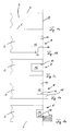
- FIG. 1 a schematically shows a part of a panel 2 that has an upper side 4, a lower side 6 opposite the upper side 4, and a side surface 8.
- the panel 2 may consist in its construction between the top 4 and bottom 6 of a variety of different layers of different materials and functionalities, which are not shown here for the sake of clarity. It can be seen in Figure a that the side surface 8 is not profiled, but was only generated by a saw cut.
- FIG. 1a shown panel 2 after in the side surface 8 a profiling 10 has been introduced.
- the profiling 10 is in all three embodiments shown of simple structure and can be introduced by the simplest milling or sawing tools.
- Figure 1c the profiling 10 in a simple groove 12, while in the Figures 1b and 1d the groove 12 has a short leg 14 and a long leg 16.
- Figure 1e shows the panel 2, in whose side surface 8, the groove 12 has been introduced after locking elements 18 have been printed.
- the applied material is shown in phantom to illustrate that it may be a different material than the materials making up the individual layers of the panel 2 as shown in FIGS FIGS. 1a to 1d has been presented.
- FIG. 2 schematically shows a section of two panels 2, which are interconnected.
- the left panel 2 has a spring 20, on the underside, a spring locking element 22 is arranged.
- the shape of the spring 20 with the spring locking element 22 located thereon can be easily produced by means of milling or sawing tools. Therefore, no locking element has been printed on the side surface 8 of the left panel 2 with a 3D printer.
- the right panel 2 has a side surface 8, in which initially a profiling 10 was introduced as a pre-profiling. For this purpose, a region has been removed in the lower left region of the right-hand panel 2, so that a projection 24 positioned on the upper side 4 is formed. In addition, a chamfer 26 was generated.
- FIG. 2 hatched the material 28 is shown by means of a 3D printer was printed. It can be seen that this material 28 forms a locking element 18, which cooperates with the spring locking element 22, so that the two panels 2 are locked in a direction perpendicular to the top 4 against each other. This means that a movement of the two panels 2 relative to each other in FIG. 2 to the right and / or left is no longer possible.
- finished profile is a snap-on profile, in which the spring locking element 22 after insertion of the spring 20 snaps into the recess 30 formed in the locking element 18.
- the material 28, which has been printed on the 3D printer have sufficient flexibility, so that a projection 32 can be bent by the spring locking element 22 downward.
- FIG. 3 shows the schematic representation of two interconnected identical panels 2, each having at its two opposite side surfaces 8 a profiling 10, which is conventionally produced by milling and / or sawing tools. However, the profilings 10 alone do not provide for a locking of the two panels in the connected state. The reached between the two panels 2 compound 34 is in the central region of FIG. 3 shown.
- a first locking element 18.1 has been attached by means of the 3D printer.
- a second locking element 18.2 which was also printed by means of a 3D printer.
- the two locking elements 18.1, 18.2 may consist of the same or different materials and, as shown in the connecting portion 34, provide for a locking of the two panels 2 relative to each other.
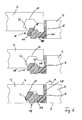
- FIG. 4 shows in the three partial views two panels 2 in different Stages during the joining of the two panels 2.
- one side face 8 of the right-hand panel 2 has no profiling, while a profiling 10 has been introduced into the side faces 8 of the left-hand panel.
- a locking element 18 which consists of a first portion 36, a second portion 38 and a third portion 40.
- the portions may consist of different materials, wherein in the illustrated embodiment, the first portion 36 and the third portion 40 of a material and the second portion 38 of a different material.
- the left panel is now lowered from top to bottom to connect the two panels together.
- a lower nose 42 meets the locking element 18.
- This is in the central region of FIG. 4 shown.
- the second portion 38 is compressed, so that the third portion 40 compared to the upper part of FIG. 4 is moved to the left.
- the material of the second portion 38 has in the illustrated embodiment, a much greater elasticity than the material of the first portion 36 or the third portion 40. In this way, can be very easily and accurately determined which portions of the printed locking elements 18 how strong and in which Direction can be compressed or bent, for example, to connect two panels together.
- FIG. 4 It is shown how the two panels abut each other in the connected state.
- the nose 42 snaps behind the locking element 8, which causes the second portion 38 to relax and expand again.
- a slot could instead be provided which is substantially perpendicular to the top 4 and bottom 6, and the portion 40 is connected only at its end portions with the portion 36.
- a part 44 of the material applied to the 3D printer 28 does not lead to a locking, but remains visible between the two upper sides 4 of the two interconnected panels 2. This can be used for decorative purposes, for example, to replicate joints between replicated tiles and / or stones.
- FIG. 5 shows that a partial printing of the side surface 8 with the material 28 is possible.
- FIG. 5 a schematic plan view of the top 4 of the panel 2, in which only the in FIG. 5 right side surface 8 was printed.
- the strength of the required locking and the direction in which the lock is to act a wide variety of locking elements can be applied to the side surface 8 with very different amounts of material 28. The less material 8 has to be applied, the more the production of the panel is accelerated. At the same time, the manufacturing costs can be reduced by the material savings.
- FIGS. 6a and 6b show more panels 2.
- the panel 2 has a top 4 and a side surface 8, in which a profiling 10 has been introduced. It can be seen in the top 4 a part 44 of the applied with the 3D printer material 28, which exercises no locking function, but is intended only as a decorative element for the top 4.
- the embodiment shown embodiment the entire side surface 8, in which a clearer simpler profiling 10 is introduced, covered with material 28 that has been applied over the 3D printer. Again, a portion 44 of the material 28 can be seen on the top 4 of the panel 2 and provides a desired decorative effect.
- the material 28 also forms a locking element 18, which in correspondingly corresponding Interlocking elements can intervene.
- locking elements 18 can be prepared having undercuts 19 which are open to the inside of the panel 2 back and can not be made with conventional sawing and / or milling tools.
- the panels 2 must be erected while performing the 3D printing.
- Such an upright positioning of the panel to be printed is in the other embodiments shown except those in the Figures 3 and 6a although not necessary, but advantageous.
- it is advantageous if the portion of the side surface 8 to be printed is aligned upward. In more complicated trained side surfaces 8, such as by pre-profiling, this can cause the panel 2 is rotated during printing or between two printing operations.
Landscapes
- Engineering & Computer Science (AREA)
- Architecture (AREA)
- Chemical & Material Sciences (AREA)
- Manufacturing & Machinery (AREA)
- Materials Engineering (AREA)
- Civil Engineering (AREA)
- Structural Engineering (AREA)
- Floor Finish (AREA)
Abstract
Die Erfindung betrifft ein Verfahren zum Herstellen eines Paneels (2), insbesondere eines Fußbodenpaneels, dass eine Oberseite (4), eine der Oberseite (4) gegenüberliegende Unterseite (6) und wenigstens eine Seitenfläche (8), an der wenigstens ein Verriegelungselement (18) angeordnet ist, aufweist, dadurch gekennzeichnet, dass das wenigstens eine Verriegelungselement (18) zumindest teilweise mittels eines 3D-Druckers auf der Seitenfläche (8) aufgedruckt wird.The invention relates to a method for producing a panel (2), in particular a floor panel, that has an upper side (4), a lower side (6) opposite the upper side (4) and at least one side surface (8) on which at least one locking element (18 ) is arranged, characterized in that the at least one locking element (18) is at least partially printed by means of a 3D printer on the side surface (8).
Description
Die Erfindung betrifft ein Verfahren zum Herstellen eines Paneels, insbesondere eines Fußbodenpaneels, das eine Oberseite, eine der Oberseite gegenüberliegende Unterseite und wenigstens eine Seitenfläche, an der wenigstens ein Verriegelungselement angeordnet ist, aufweist. Die Erfindung betrifft zudem eine Vorrichtung zum Durchführen eines derartigen Verfahrens.The invention relates to a method for producing a panel, in particular a floor panel, which has an upper side, a lower side opposite the upper side and at least one side surface, on which at least one locking element is arranged. The invention also relates to an apparatus for carrying out such a method.
Fußbodenpaneele in Form eines Laminatfußbodens bilden einen der weltweit am weitesten verbreiteten Bodenbeläge. Während ein derartiger Laminatfußboden ursprünglich aus einer Vielzahl von einzelnen Paneelen bestand, die miteinander verleimt werden mussten, hat sich im Stand der Technik die leimlose Verlegung beispielsweise unter dem Begriff "Klicklaminat" durchgesetzt. Einzelne Paneele, insbesondere Fußbodenpaneele aber auch Paneele beispielsweise für Decken oder Wandverkleidungen, verfügen dabei über eine Oberseite, die zumeinst mit einem Dekor versehen ist. An der Unterseite ist ein Verwerfungen des Paneels entgegenwirkender Gegenzug aufgebracht, und es können weitere Funktionsschichten, wie beispielsweise Trittschalldämmungen, aufgebracht werden. Die Seitenflächen werden in der Regel mit Verriegelungselementen ausgestattet, die so ausgebildet sind, dass zwei identische Paneele miteinander verbunden werden können. Eine Verriegelung der beiden Paneele in einer Bewegungsrichtung bedeutet dabei, dass eine Bewegung der beiden Paneele relativ zueinander entlang dieser Richtung aufgrund der Ausgestaltung der Verriegelungselemente nicht möglich ist. Die Festigkeit und Stabilität eines beispielsweise aus Fußbodenpaneelen zusammengesetzten Fußbodens hängt dabei maßgeblich von der Festigkeit und Stabilität der Verriegelungselemente ab, da diese einen Großteil der auf die einzelnen Fußbodenpaneele wirkenden Belastungen aufnehmen. Dies gilt insbesondere, wenn die einzelnen Paneele auf einem unebenen Untergrund verlegt werden.Floor panels in the form of a laminate floor form one of the world's most widely used floor coverings. While such a laminate floor originally consisted of a plurality of individual panels which had to be glued together, in the prior art the glueless laying has gained acceptance, for example, by the term "click laminate". Individual panels, in particular floor panels but also panels, for example, for ceilings or wall coverings, have an upper surface, which is at one time provided with a decor. At the bottom of a panel of the panel counteracting Gegenzug is applied, and it can be more functional layers, such as impact sound insulation applied. The side surfaces are usually equipped with locking elements that are designed so that two identical panels can be connected to each other. A locking of the two panels in a direction of movement means that a movement of the two panels relative to each other along this direction due to the design of the locking elements is not possible. The strength and stability of a For example, composed of floor panels floor depends largely on the strength and stability of the locking elements, since they absorb a majority of the forces acting on the individual floor panels loads. This is especially true if the individual panels are laid on an uneven surface.
Paneele und insbesondere Fußbodenpaneele bestehen in der Regel aus einem Kern, der oftmals aus einer Holzwerkstoffplatte, beispielsweise einer hochdichten Faserplatte (HDF) oder einer mitteldichten Faserplatte (MDF) besteht. Auch andere Holzwerkstoffplatten und Werkstoffe sind als Kern bereits verwendet worden. Auf der Oberseite werden Beschichtungen aufgebracht, die einerseits das optische Erscheinungsbild der Paneele und andererseits Eigenschaften der insbesondere bei Fußbodenpaneelen stark belasteten Oberseite bestimmen. Dies können die Abriebfestigkeit erhöhende Schichten oder andere Schutzschichten sein. Auf der Unterseite wird, wie bereits dargelegt, der Gegenzug und gegebenenfalls eine Trittschalldämmung aufgebracht. Die Verriegelungselemente werden jedoch aus dem Kernmaterial des Paneels gefertigt und oftmals aus den Seitenflächen einer fertigen Platte herausgefräst. Um die Qualitätskriterien für leimlose Profile, beispielsweise die Festigkeit oder die Auszugsfestigkeit, zu erfüllen, muss das Trägermaterial beispielsweise eine relativ hohe Rohdichte besitzen, um anspruchsvolle und gegebenenfalls komplizierte Profile der Verriegelungselemente überhaupt erstellen zu können. Dies hat zur Folge, dass insbesondere Holzwerkstoffplatten mit einem hohen Leimanteil hergestellt werden müssen, wodurch die Platten selbst schwer und die Kosten für das Produkt unnötig hoch sind. Zudem bedeutet eine hohe Rohdichte und ein hoher Leimanteil, dass der Kern, beispielsweise eine HDF-Platte relativ starr und unelastisch wird, was für eine Vielzahl leimloser Profile ungünstig ist. Während im Bereich der Verriegelungselemente diese erhöhte Festigkeit durchaus Vorteile hat, wird entlang der Fläche des aus den Paneelen verlegten Fußbodens eher eine gewisse Elastizität gewünscht.Panels and in particular floor panels usually consist of a core, which often consists of a wood-based panel, for example a high-density fiberboard (HDF) or a medium-density fiberboard (MDF). Other wood-based panels and materials have already been used as a core. On top of coatings are applied, which determine the one hand, the visual appearance of the panels and on the other hand properties of the particular floor panels heavily loaded top. These may be the abrasion resistance enhancing layers or other protective layers. On the underside, as already stated, the counter-pull and possibly a footfall sound insulation applied. However, the locking elements are made of the core material of the panel and often milled out of the side surfaces of a finished panel. In order to meet the quality criteria for glueless profiles, such as the strength or the pull-out strength, the carrier material, for example, must have a relatively high density in order to create sophisticated and possibly complicated profiles of the locking elements at all. This has the consequence that in particular wood-based panels must be made with a high proportion of glue, whereby the plates themselves are heavy and the cost of the product unnecessarily high. In addition, a high density and a high amount of glue means that the core, for example, an HDF board is relatively rigid and inelastic, which is unfavorable for a variety of glueless profiles. While this increased strength has advantages in the area of the locking elements, a certain elasticity is more desired along the surface of the floor laid out of the panels.
Versuche, auf andere Trägermaterialien für den Kern des Paneels zu wechseln sind im Stand der Technik durchaus unternommen worden. So wurden Versuche mit Platten unternommen, deren Kern einen mehr oder weniger hohen Kunststoffanteil aufweist und aus einem so genannten WPC-Material (WPC: wood plastic composite) bestehen. Eine Beschichtung solcher Platten ist allerdings nicht ohne weiteres möglich. Dadurch werden die Kosten jedoch weiter erhöht. Zudem stehen Platten aus derartigen Materialien nicht in der benötigen Menge oder den benötigten Formen zur Verfügung.Attempts to change to other support materials for the core of the panel have certainly been made in the prior art. Thus, attempts were made with plates whose core has a more or less high plastic content and consist of a so-called WPC material (WPC: wood plastic composite). However, a coating of such plates is not readily possible. However, this will further increase costs. In addition, plates made of such materials are not available in the required quantity or the required shapes.
Unabhängig davon welches Material als Trägermaterial für das Paneel verwendet wird, werden die Profile in der Regel durch Sägen oder Fräsen erzeugt, so dass bestimmte Profilformen der Verriegelungselemente, beispielsweise mit komplizierten oder ineinander eingreifende Hinterschneidungen, allein aus diesem Grund nicht herstellbar sind. Dies führt dazu, dass höherwertige Profile für Verriegelungselemente, die zu besseren Auszugswerten oder weniger Materialverbrauch führten, technisch nicht hergestellt werden können.Regardless of which material is used as the carrier material for the panel, the profiles are usually produced by sawing or milling, so that certain profile shapes of the locking elements, for example, with complicated or intermeshing undercuts, alone for this reason can not be produced. As a result, higher-quality profiles for locking elements, which led to better pull-out values or less material consumption, can not be manufactured technically.
Der Erfindung liegt daher die Aufgabe zugrunde, ein Verfahren und eine Vorrichtung zum Durchführen des Verfahrens vorzuschlagen, mit denen die Nachteile aus dem Stand der Technik behoben werden.The invention is therefore based on the object to propose a method and an apparatus for carrying out the method with which the disadvantages of the prior art are eliminated.
Die Erfindung löst die gestellte Aufgabe durch ein Verfahren zum Herstellen eines Paneels, insbesondere eines Fußbodenpaneels, das eine Oberseite, eine der Oberseite gegenüberliegende Unterseite und wenigstens eine Seitenfläche, an der wenigstens ein Verriegelungselement angeordnet ist, aufweist, wobei sich das Verfahren dadurch auszeichnet, dass das wenigstens eine Verriegelungselement zumindest teilweise mittels eines 3D-Druckers auf die Seitenfläche aufgedruckt wird.The invention achieves the stated object by a method for producing a panel, in particular a floor panel, which has an upper side, an underside opposite the upper side and at least one side surface on which at least one locking element is arranged, wherein the method is characterized in that the at least one locking element is at least partially printed by means of a 3D printer on the side surface.
Da das Verriegelungselement zumindest teilweise auf die Seitenfläche aufgedruckt wird, kommt es hier zu einer ausreichend festen und stabilen Verbindung zwischen beispielsweise dem Kernmaterial des Paneels und dem aufgedruckten Verriegelungselement. Gleichzeitig kann für das Verriegelungselement ein Material gewählt werden, das nicht gleichzeitig das Material des Kerns des Paneels ist. Auf diese Weise ist es möglich, das Kernmaterial des Paneels auf die geforderten Eigenschaften hin zu optimieren und gleichzeitig Verriegelungselemente bereitzustellen, die andere Eigenschaften aufweisen und auf die Bedürfnisse bei Verriegelungselementen optimiert sind.Since the locking element is at least partially printed on the side surface, it comes here to a sufficiently strong and stable connection between, for example, the core material of the panel and the printed locking element. At the same time, a material can be chosen for the locking element, which is not the material of the core of the panel at the same time. In this way, it is possible to optimize the core material of the panel to the required properties and at the same time provide locking elements that have different properties and are optimized for the needs of locking elements.
Bei dem erfindungsgemäßen Verfahren werden die Verriegelungselemente folglich aufgebaut. Dies geschieht bei 3D-Druckern in der Regel in Form einer Vielzahl dünner Schichten des aufgebrachten Materials. Es ist daher nicht nötig, die Verriegelungselemente, wie dies im Stand der Technik bekannt ist, aus dem eigentlichen Paneel beziehungsweise dessen Kernmaterial herauszusägen oder herauszufräsen. Die damit verbundenen Einschränkungen der möglichen Strukturen, Richtungen und Werkzeuge sind beim erfindungsgemäßen Verfahren nicht mehr vorhanden. Durch das Aufdrucken der Verriegelungselemente in gegebenenfalls einer Vielzahl dünner Schichten lassen sich auch komplizierteste Profile für die einzelnen Verriegelungselemente realisieren, so dass neben dem für die Anforderungen von Verriegelungselementen optimierten Material auch beispielsweise bezüglich der Auszugfestigkeit optimierte oder verbesserte Profile für die einzelnen Verriegelungselemente verwendet werden können.In the method according to the invention, the locking elements are consequently constructed. For 3D printers, this usually takes the form of a large number of thin layers of applied material. It is therefore not necessary to cut or mill out the locking elements, as is known in the art, from the actual panel or its core material. The associated limitations of possible structures, directions and tools are no longer present in the method according to the invention. By printing the locking elements in optionally a plurality of thin layers even the most complicated profiles for the individual locking elements can be realized so that in addition to the optimized material for the requirements of locking elements optimized and improved profiles for the individual locking elements can be used for example with respect to the pull-out strength.
In einer bevorzugten Ausgestaltung verfügt das Paneel, insbesondere das Fußbodenpaneel, folglich über einen Kern beispielsweise aus einer leichten Holzwerkstoffplatte. Bei dieser ist gegenüber den bisher verwendeten dichten oder hochdichten Faserplatten der Leimanteil reduziert, wodurch neben dem Gewicht auch die Herstellungskosten reduziert werden können. Diese Paneele sind für den Endanwender folglich einfacher und leichter zu handhaben, sind leichter zu transportieren und weisen bessere Eigenschaften aufgrund der gegebenenfalls höheren Elastizität auf.In a preferred embodiment, the panel, in particular the floor panel, consequently has a core, for example, of a light wood-based panel. In this case, the glue content is reduced compared to the previously used dense or high-density fiberboard, which in addition to the weight and the manufacturing cost can be reduced. Consequently, these panels are easier and easier to handle for the end user, are easier to transport and have better properties due to the possibly higher elasticity.
Vorteilhafterweise werden an wenigstens zwei aneinander gegenüberliegenden Seitenflächen zueinander korrespondierende Verriegelungselemente jeweils wenigstens teilweise mittels eines 3D-Druckers auf der jeweiligen Seitenfläche aufgedruckt.Advantageously, at least two mutually opposite side surfaces mutually corresponding locking elements are each at least partially printed by means of a 3D printer on the respective side surface.
Unabhängig davon, auf wievielen Seitenflächen Verriegelungselemente mit dem 3D-Drucker aufgedruckt werden, können die Verriegelungselemente natürlich auch vollständig durch den 3D-Drucker aufgedruckt werden. Insbesondere, falls an gegenüberliegenden Seitenflächen die Verriegelungselemente mit dem 3D-Drucker aufgedruckt werden, ist es möglich, die einzelnen Profile besonders genau aufeinander abzustimmen. Es ist nicht mehr nötig, für unterschiedliche Profile der einzelnen Verriegelungselemente unterschiedliche Werkzeuge vorzuhalten, die möglichst exakt in die jeweilige Werkzeugmaschine eingesetzt und insbesondere möglichst exakt relativ zum eigentlichen Paneel ausgerichtet werden müssen. Vielmehr ist es beispielsweise möglich, die Position des Paneels zu erfassen und beispielsweise einen Druckkopf des 3D-Drucker anhand dieser erfassten Position der Seitenfläche des Paneels auszurichten. Auch dadurch wird das Herstellungsverfahren beschleunigt und die Herstellungskosten werden gesenkt.Regardless of how many side surfaces locking elements are printed with the 3D printer, of course, the locking elements can also be completely printed by the 3D printer. In particular, if on opposite side surfaces, the locking elements are printed with the 3D printer, it is possible to match the individual profiles particularly closely to each other. It is no longer necessary to provide for different profiles of the individual locking elements different tools that must be used as accurately as possible in the respective machine tool and in particular must be aligned as accurately as possible relative to the actual panel. Rather, it is for example possible to detect the position of the panel and, for example, to align a print head of the 3D printer based on this detected position of the side surface of the panel. This also speeds up the manufacturing process and reduces manufacturing costs.
Vorzugsweise sind die beiden korrespondierenden Verriegelungselemente ausgebildet, zwei identische Paneele, insbesondere Fußbodenpaneele, miteinander zu verbinden und in wenigstens eine, bevorzugte wenigstens zwei Raumrichtungen relativ zueinander zu verriegeln. Derartige Profile sind aus dem Stand der Technik bereits bekannt. Die Verriegelung entlang einer Richtung bedeutet, dass eine Bewegung der beiden Paneele relativ zueinander in dieser Richtung nicht mehr möglich ist. Aus dem Stand der Technik sind beispielsweise Profile für Verriegelungselemente bekannt, bei denen die einzelnen Paneele beispielsweise in einer Richtung senkrecht zur Oberseite der unterschiedlichen Paneele und in einer Richtung senkrecht zur Seitenfläche der Paneele, entlang derer die beiden Paneele miteinander verbunden sind, nicht mehr verschoben werden können. Eine Verschiebung der beiden Paneele relativ zueinander entlang der Seitenfläche ist jedoch weiterhin möglich.Preferably, the two corresponding locking elements are designed to connect two identical panels, in particular floor panels, to one another and to lock them in at least one, preferably at least two spatial directions relative to one another. Such profiles are already known from the prior art. The locking along one direction means that a movement of the two panels relative to each other in this direction is no longer possible. For example, profiles for locking elements are known from the prior art in which the individual panels are no longer displaced, for example in a direction perpendicular to the top of the different panels and in a direction perpendicular to the side surface of the panels, along which the two panels are interconnected can be. However, a displacement of the two panels relative to each other along the side surface is still possible.
Als vorteilhaft hat sich herausgestellt, wenn vor dem Aufdrucken eine Vorprofilierung in die Seitenfläche eingebracht wird. Diese kann vorteilhafterweise in Form einer Nut, einer Feder und/oder einem modifizierten Falz vorhanden sein. Dadurch kann der Materialaufwand für den 3D-Druck reduziert werden, was zu einer weiteren Reduzierung der Herstellungskosten und zu einer Beschleunigung des Verfahrens führt. Insbesondere für den Fall, dass die Verriegelungsprofile über massive Anteile verfügen, können diese aus einem Material des Paneels, beispielsweise des Kerns, hergestellt werden. Da 3D-Drucker das aufzubringende Material in Form einer Vielzahl dünner Schichten aufbringen, ist der Herstellungsaufwand für derart massive Bauteile oder Teile davon mittels des Druckers relativ hoch.It has proven to be advantageous if a pre-profiling is introduced into the side surface before printing. This may advantageously be present in the form of a groove, a spring and / or a modified fold. As a result, the material costs for the 3D printing can be reduced, which leads to a further reduction of the production costs and to an acceleration of the method. In particular, in the event that the locking profiles have massive proportions, they can be made of a material of the panel, such as the core. Since 3D printers apply the material to be applied in the form of a plurality of thin layers, the production cost for such massive components or parts thereof by means of the printer is relatively high.
Werden die Profilierungen in die Seitenfläche eingebracht, können diese sehr einfache Formen, beispielsweise eine einfache Nut oder eine einfache Feder, beinhalten. Diese sind mittels Standardfräs- oder -sägewerkzeugen kostengünstig, schnell und genau herstellbar.If the profilings are introduced into the side surface, they can contain very simple shapes, for example a simple groove or a simple spring. These can be inexpensively, quickly and accurately produced by means of standard milling or sawing tools.
Vorteilhafterweise wird zum Aufdrucken des wenigstens einen Verriegelungselementes wenigstens ein thermoplastischer Kunststoff und/oder wenigstens ein strahlenhärtbarer Lack verwendet. So kann der 3D-Drucker beispielsweise nach dem Fused Deposition Modelling-Verfahren funktionieren, bei dem aufgeschmolzene Thermoplaste schichtweise aufgetragen werden. Alternativ dazu kann auch ein 3D-Drucker nach dem Multi Jet Modelling-Verfahren verwendet werden, bei dem mit härtbaren Lacken, die beispielsweise durch UV-Strahlung oder Elektronenstrahlen gehärtet werden können, gearbeitet wird. Unabhängig von der Art des Materials können verschiedenste Eigenschaften durch Variationen der Vorprodukte angepasst werden.Advantageously, at least one thermoplastic and / or at least one radiation-curable lacquer is used to print the at least one locking element. For example, the 3D printer can function according to the fused deposition modeling process, in which molten thermoplastics are applied in layers. Alternatively, a 3D printer according to the multi-jet modeling method can be used, in which work is carried out with curable coatings, which can be cured, for example, by UV radiation or electron beams. Regardless of the type of material, a wide variety of properties can be adjusted by variations of the precursors.
Vorzugsweise wird vor dem Aufdrucken des Materials mit dem 3D-Drucker ein Primer oder eine Grundierung auf die Seitenfläche aufgebracht, um eine bessere Haftung des aufzubringenden Materials zu gewährleisten.Preferably, prior to printing the material with the 3D printer, a primer or primer is applied to the side surface to provide better adhesion of the material to be applied.
In einer bevorzugten Ausgestaltung des Verfahrens wird die gesamte Seitenfläche mittels des 3D-Druckers bedruckt. Auf diese Weise ist es besonders einfach möglich, beispielsweise die Trägerplatte oder den Kern des Paneels gegen das Eindringen von Wasser zu versiegeln, so dass beispielsweise auch Fußbodenpaneele für Feuchträume, beispielsweise Badezimmer, herstellbar sind. Da dies im gleichen Arbeitsschritt wie das Aufbringen der Verriegelungselemente geschieht, ist anders als bei Verfahren aus dem Stand der Technik, in denen die Versiegelung einen separaten Arbeitsschritt bedeutet, das Verfahren gemäß der vorliegenden Erfindung weiterhin in ökonomischer sinnvoller Weise durchzuführen.In a preferred embodiment of the method, the entire side surface is printed by means of the 3D printer. In this way, it is particularly easy to seal, for example, the support plate or the core of the panel against the ingress of water, so that, for example, floor panels for wet rooms, such as bathrooms, can be produced. Since this is done in the same operation as the application of the locking elements, unlike the prior art methods in which the sealing means a separate operation, the method according to the present invention continues to be carried out in an economically sensible manner.
Vorzugsweise wird die Seitenfläche des Paneels mittels des 3D-Druckers wenigstens teilweise entlang wenigstens einer Seitenkante der Seitenfläche bedruckt. Diese wenigstens eine Seitenkante ist dabei vorteilhafterweise die Kante, an der die Seitenfläche mit der Oberseite des Paneels zusammentrifft. Auf diese Weise lassen sich die durch den 3D-Drucker aufzubringenden Materialien auch zu dekorativen Zwecken an der Oberseite des Paneels verwenden. Dazu ist es von Vorteil, wenn die Seitenfläche vollständig wenigstens entlang dieser Seitenkante bedruckt wird. Dies kann jedoch mit unterschiedlichen Materialien geschehen, sodass durch den so zu erreichenden Materialmix entlang dieser Seitenkante dekorative Effekte hervorgerufen werden können.Preferably, the side surface of the panel is printed by the 3D printer at least partially along at least one side edge of the side surface. This at least one side edge is advantageously the edge at which the side surface coincides with the top of the panel. In this way, the materials to be applied by the 3D printer can also be used for decorative purposes on the top of the panel. For this purpose, it is advantageous if the side surface is completely printed at least along this side edge. However, this can be done with different materials, so that decorative effects can be caused by the material mix to be achieved along this side edge.
Alternativ oder zusätzlich dazu kann die Seitenfläche auch entlang der gegenüberliegenden Seitekante wenigstens teilweise, vorteilhafterweise jedoch vollständig bedruckt werden. An dieser gegenüberliegenden Seitenkante stoßen folglich die Seitenfläche des Paneels und die Unterseite des Paneels aneinander.Alternatively or additionally, the side surface along the opposite side edge at least partially, but advantageously completely printed. Consequently, at this opposite side edge, the side surface of the panel and the underside of the panel abut each other.
Als vorteilhaft hat sich herausgestellt, wenn ein Teil des mittels des 3D-Druckers aufgebrachten Materials einen Teil der Oberseite des Paneels bildet. In diesem Fall wird beispielsweise an der Kante, an der die Seitenfläche mit der Oberseite zusammentrifft, wenigstens eine Schicht eines Materials mit dem 3D-Drucker aufgetragen. Im verlegten Zustand, in dem zwei Paneele miteinander verbunden sind, ist dieses Material daher sichtbar und kann für dekorative und ästhetische Zwecke verwendet werden. Da es sich bei dem mit dem 3D-Drucker aufgebrachten Material in der Regel um einen anderen Werkstoff handelt, als er für den Rest der Oberseite des Paneels verwendet wird, lassen sich eine Vielzahl unterschiedlicher dekorativer Effekte erzielen. So ist beispielsweise auch die Erzeugung von Oberflächenstrukturen in dem Bereich der Oberseite, der durch das Material, das mit dem 3D-Drucker aufgebracht wird, gebildet wird, leicht möglich. Auch große und insbesondere tiefe Strukturen lassen sich mittels des 3D-Druckers einfach erzeugen, so dass beispielsweise Fliesenfugen oder Fugen zwischen Steinplatten besonders einfach und realistisch nachgebildet werden können. Durch die für den 3D-Druck verwendeten Materialien können außerdem auch andere Funktionalitäten wie z.B. die elektrische Leitfähigkeit, eine Informationsleitung oder eine Lichtleitung erzeugt werden.It has proven to be advantageous if a part of the material applied by means of the 3D printer forms part of the top side of the panel. In this case, for example, at the edge where the side surface meets the top, at least one layer of material is applied with the 3D printer. In the installed state, in which two panels are connected to each other, this material is therefore visible and can be used for decorative and aesthetic purposes. Since the material applied to the 3D printer is typically a different material than that used for the remainder of the top of the panel, a variety of different decorative effects can be achieved. For example, the generation of surface structures in the area of the top formed by the material applied to the 3D printer is also easily possible. Even large and especially deep structures can be easily generated by means of the 3D printer, so that, for example, tile joints or joints between stone slabs can be replicated particularly simply and realistically. The materials used for 3D printing may also include other functionalities such as e.g. the electrical conductivity, an information line or a light pipe are generated.
Vorteilhafterweise ist dabei der Teil des aufgedruckten Materials, der den Teil der Oberseite des Paneels bildet, kein Verriegelungselement, sondern dient insbesondere ausschließlich dekorativen Zwecken.Advantageously, while the part of the printed material, which forms the part of the top of the panel, no locking element, but in particular serves exclusively decorative purposes.
In einem bevorzugten Ausführungsbeispiel des Verfahrens weist das aufgedruckte Verriegelungselement mehrere, insbesondere zwei, unterschiedliche Materialien auf, die mit dem 3D-Drucker aufgedruckt werden. Dabei können unterschiedliche 3D-Drucker oder ein 3D-Drucker mit unterschiedlichen Druckköpfen verwendet werden. Prinzipiell ist es auch möglich, den gleichen Druckkopf eines 3D-Druckers für unterschiedliche Materialien zu verwenden.In a preferred embodiment of the method, the printed-on locking element has a plurality of, in particular two, different materials which are printed with the 3D printer. Different 3D printers or a 3D printer with different print heads can be used. In principle, it is also possible to use the same print head of a 3D printer for different materials.
Die Verwendung verschiedener Materialien mit unterschiedlichen Festigkeits-, Elastizitäts- und Stabilitätseigenschaften vergrößert die Flexibilität des Verfahrens und die Vielfalt der möglichen Verriegelungselemente.The use of different materials with different strength, elasticity and stability properties increases the flexibility of the process and the variety of possible locking elements.
So kann beispielsweise ein Anteil des Verriegelungselementes elastischer ausgebildet sein als ein benachbarter Anteil, so dass beispielsweise beim Verbinden der Paneele das Verriegelungselement an der Stelle zusammengedrückt werden kann, an der das Material mit der höheren Elastizität vorliegt. Nachdem die einzelnen Paneele in ihre endgültigen Positionen gebracht wurden, kann das so zusammengedrückte Verriegelungselement entspannen und beispielsweise in eine dafür vorgesehene Hinterschneidung einschnappen. Anders als bei Verriegelungselementen aus dem Stand der Technik, die vollständig aus dem gleichen Material bestehen, ist es auf diese Weise möglich, die besonders belasteten Bereiche der Verriegelungselemente besonders elastisch auszubilden und somit ein Abbrechen zu vermeiden.Thus, for example, a portion of the locking element may be designed to be more elastic than an adjacent portion, so that, for example, when connecting the panels, the locking element can be compressed at the point where the material with the higher elasticity is present. After the individual panels have been brought into their final positions, the thus compressed locking element can relax and snap, for example, in a designated undercut. Unlike locking elements of the prior art, which are made entirely of the same material, it is possible in this way to form the particularly loaded areas of the locking elements particularly elastic and thus to avoid breakage.
Vorzugsweise wird das Paneel mit der durch den 3D-Drucker zu bedruckenden Seitenfläche nach oben angeordnet. Auf diese Weise kann das durch den Drucker aufgebrachte Material der Schwerkraft folgend aufgebracht werden und ein Zerfließen oder Zerschmieren im noch nicht ausgehärteten Zustand wird weitestgehend oder sogar vollständig verhindert. Werden unterschiedliche Seitenflächen mit wenigstens einem 3D-Drucker beschichtet, ist es von Vorteil, die jeweils zu bedruckende Seitenfläche nach oben auszurichten und somit das Paneel zwischen einzelnen Druckvorgängen auf den unterschiedlichen Seitenflächen zu drehen.Preferably, the panel with the side surface to be printed by the 3D printer is arranged upward. In this way, the material applied by the printer can be applied following the gravitational force, and a bleeding or greasing in the uncured state is largely or even completely prevented. If different side surfaces are coated with at least one 3D printer, it is advantageous to align the respective side surface to be printed upwards and thus to rotate the panel between individual printing processes on the different side surfaces.
Die Erfindung löst die gestellte Aufgabe zudem durch eine Vorrichtung zum Durchführen eines hier beschriebenen Verfahrens, die wenigstens einen 3D-Drucker zum Aufdrucken wenigstens eines Teils des wenigstens einen Verriegelungselementes aufweist. Vorteilhafterweise verfügt der wenigstens eine 3D-Drucker über wenigstens zwei Druckköpfe, durch die unterschiedliche Materialien aufgedruckt werden können. Derartige 3D-Drucker sind aus dem Stand der Technik prinzipiell bekannt. Vorzugsweise verfügt die Vorrichtung zudem über eine Profilierungseinrichtung zum Einbringen einer Profilierung in wenigstens eine Seitenfläche eines Paneels. Auf diese Weise lässt sich zunächst die Profilierung einbringen, wobei die unterschiedlichen Anteile des so eingebrachten Profils anschließend mit dem Teil der Verriegelungselemente bedruckt werden können, die durch den 3D-Drucker aufgebracht werden.The invention also achieves the stated object by a device for carrying out a method described here, which has at least one 3D printer for printing on at least one part of the at least one locking element. Advantageously, the at least one 3D printer has at least two print heads through which different materials can be printed. Such 3D printers are known in principle from the prior art. Preferably, the device also has a profiling device for introducing a profiling in at least one side surface of a panel. In this way, initially the profiling can be introduced, wherein the different proportions of the profile thus introduced can then be printed with the part of the locking elements which are applied by the 3D printer.
Die Erfindung löst die gestellte Aufgabe zudem durch ein Paneel, insbesondere ein Fußbodenpaneel, das durch eines der hier beschriebenen Verfahren herstellbar ist.The invention solves this problem by a panel, in particular a floor panel, which can be produced by one of the methods described herein.
Mit Hilfe der beiliegenden Figuren werden nachfolgend Ausführungsbeispiele der vorliegenden Erfindung näher erläutert. Es zeigt
- Figuren 1a bis 1e
- - die schematische Darstellung eines Teils eines Paneels nach unterschiedlichen Verfahrensschritten,
Figur 2- - die schematische Darstellung eines Verbindungsanteils zwischen zwei Paneelen,
- Figur 3
- - eine weitere schematische Darstellung zweier miteinander verbundenen Paneele,
Figur 4- - unterschiedliche Stadien während des Verbindens zweier Paneele,
Figur 5- - die schematische Darstellung eines Teils eines Paneels,
- Figur 6a und 6b
- - zwei weitere Ausführungsformen eines Paneels,
- Figur 7
- - eine weitere Variante einer Ausführungsform eines Paneels.
- FIGS. 1a to 1e
- the schematic representation of a part of a panel according to different method steps,
- FIG. 2
- the schematic representation of a connection portion between two panels,
- FIG. 3
- a further schematic representation of two interconnected panels,
- FIG. 4
- different stages during the joining of two panels,
- FIG. 5
- the schematic representation of a part of a panel,
- FIGS. 6a and 6b
- two further embodiments of a panel,
- FIG. 7
- - Another variant of an embodiment of a panel.
Die
Durch das Aufdrucken können komplizierteste Strukturen und Formen sowie unterschiedliche Materialien realisiert werden.By printing the most complicated structures and shapes as well as different materials can be realized.
Auch in
An der jeweils rechten Seitenfläche 8 der beiden Paneele 2 ist mittels des 3D-Druckers ein erstes Verriegelungselement 18.1 angebracht worden. An der gegenüberliegenden zweiten Seitenfläche 8 befindet sich ein zweites Verriegelungselement 18.2, das ebenfalls mittels eines 3D-Druckers aufgedruckt wurde. Die beiden Verriegelungselemente 18.1, 18.2 können aus dem gleichen oder aus unterschiedlichen Materialen bestehen und sorgen, wie im Verbindungsbereich 34 dargestellt ist, für eine Verriegelung der beiden Paneele 2 relativ zueinander.On the respective
Im in
Im unteren Bereich der
Man erkennt, das ein Teil 44 des mit dem 3D-Drucker aufgebrachten Materials 28 nicht zu einer Verriegelung führt, wohl aber zwischen den beiden Oberseiten 4 der beiden miteinander verbundenen Paneele 2 sichtbar bleibt. Dies kann zu Dekorationszwecken verwendet werden, um beispielsweise Fugen zwischen nachgebildeten Fliesen und/oder Steinen nachzubilden.It can be seen that a
Während im in
Wie
- 22
- Paneelpaneling
- 44
- Oberseitetop
- 66
- Unterseitebottom
- 88th
- Seitenflächeside surface
- 1010
- Profilierungprofiling
- 1212
- Nutgroove
- 1414
- kurzer Schenkelshort thigh
- 1616
- langer Schenkellong thigh
- 1818
- Verriegelungselementlocking element
- 18.118.1
- erstes Verriegelungselementfirst locking element
- 18.218.2
- zweites Verriegelungselementsecond locking element
- 1919
- Hinterschneidungundercut
- 2020
- Federfeather
- 2222
- FederverriegelungselementSpring locking element
- 2424
- ÜberstandGot over
- 2626
- Fasechamfer
- 2828
- Materialmaterial
- 3030
- Ausnehmungrecess
- 3232
- Vorsprunghead Start
- 3434
- Verbindungconnection
- 3636
- erster Anteilfirst share
- 3838
- zweiter Anteilsecond share
- 4040
- dritter Anteilthird share
- 4242
- Nasenose
- 4444
- Teilpart
Claims (15)
Priority Applications (8)
| Application Number | Priority Date | Filing Date | Title |
|---|---|---|---|
| EP14002024.9A EP2955295B1 (en) | 2014-06-12 | 2014-06-12 | Method for manufacturing a panel |
| PL14002024T PL2955295T3 (en) | 2014-06-12 | 2014-06-12 | Method for manufacturing a panel |
| ES14002024.9T ES2664105T3 (en) | 2014-06-12 | 2014-06-12 | Procedure for the manufacture of a panel |
| PT140020249T PT2955295T (en) | 2014-06-12 | 2014-06-12 | Method for manufacturing a panel |
| PT150014611T PT2955296T (en) | 2014-06-12 | 2015-05-15 | Method for manufacturing a panel and panel |
| EP15001461.1A EP2955296B1 (en) | 2014-06-12 | 2015-05-15 | Method for manufacturing a panel and panel |
| PL15001461T PL2955296T3 (en) | 2014-06-12 | 2015-05-15 | Method for manufacturing a panel and panel |
| ES15001461.1T ES2669437T3 (en) | 2014-06-12 | 2015-05-15 | Procedure to manufacture a panel and panel |
Applications Claiming Priority (1)
| Application Number | Priority Date | Filing Date | Title |
|---|---|---|---|
| EP14002024.9A EP2955295B1 (en) | 2014-06-12 | 2014-06-12 | Method for manufacturing a panel |
Publications (2)
| Publication Number | Publication Date |
|---|---|
| EP2955295A1 true EP2955295A1 (en) | 2015-12-16 |
| EP2955295B1 EP2955295B1 (en) | 2018-02-28 |
Family
ID=50943026
Family Applications (2)
| Application Number | Title | Priority Date | Filing Date |
|---|---|---|---|
| EP14002024.9A Active EP2955295B1 (en) | 2014-06-12 | 2014-06-12 | Method for manufacturing a panel |
| EP15001461.1A Active EP2955296B1 (en) | 2014-06-12 | 2015-05-15 | Method for manufacturing a panel and panel |
Family Applications After (1)
| Application Number | Title | Priority Date | Filing Date |
|---|---|---|---|
| EP15001461.1A Active EP2955296B1 (en) | 2014-06-12 | 2015-05-15 | Method for manufacturing a panel and panel |
Country Status (4)
| Country | Link |
|---|---|
| EP (2) | EP2955295B1 (en) |
| ES (2) | ES2664105T3 (en) |
| PL (2) | PL2955295T3 (en) |
| PT (2) | PT2955295T (en) |
Cited By (3)
| Publication number | Priority date | Publication date | Assignee | Title |
|---|---|---|---|---|
| AT518080A4 (en) * | 2015-11-30 | 2017-07-15 | Greiner Perfoam Gmbh | Method for producing a motor vehicle interior component |
| AT518085B1 (en) * | 2015-11-30 | 2017-07-15 | Greiner Perfoam Gmbh | Method for producing a motor vehicle interior component |
| DE102016115886A1 (en) | 2016-08-26 | 2018-03-01 | Guido Schulte | Plate-shaped component |
Families Citing this family (4)
| Publication number | Priority date | Publication date | Assignee | Title |
|---|---|---|---|---|
| US20200056380A1 (en) * | 2018-08-16 | 2020-02-20 | Zhejiang Kingdom Plastics Industry Co., Ltd. | Chamfered Plastic Floor |
| DE102019117425A1 (en) * | 2019-06-27 | 2020-12-31 | Guido Schulte | Plate-shaped component and method for its manufacture |
| DE102019117426A1 (en) * | 2019-06-27 | 2020-12-31 | Guido Schulte | Plate-shaped component |
| CN113502999B (en) * | 2021-07-28 | 2022-06-10 | 广州海鸥住宅工业股份有限公司 | Concatenation formula 3D prints waterproof chassis |
Citations (4)
| Publication number | Priority date | Publication date | Assignee | Title |
|---|---|---|---|---|
| WO2002060691A1 (en) * | 2001-01-31 | 2002-08-08 | Pergo Ab | A process for the manufacturing of joining profiles |
| DE202011109396U1 (en) * | 2011-12-22 | 2012-01-26 | Jörg Paetrow | Plate-shaped elements for covering surfaces |
| WO2014011110A1 (en) * | 2012-07-13 | 2014-01-16 | Floor Iptech Ab | Method of coating a building panel with digital printing/coating technique |
| US20140017452A1 (en) * | 2012-07-13 | 2014-01-16 | Floor Iptech Ab | Digital coating and printing |
-
2014
- 2014-06-12 PT PT140020249T patent/PT2955295T/en unknown
- 2014-06-12 PL PL14002024T patent/PL2955295T3/en unknown
- 2014-06-12 EP EP14002024.9A patent/EP2955295B1/en active Active
- 2014-06-12 ES ES14002024.9T patent/ES2664105T3/en active Active
-
2015
- 2015-05-15 PT PT150014611T patent/PT2955296T/en unknown
- 2015-05-15 EP EP15001461.1A patent/EP2955296B1/en active Active
- 2015-05-15 PL PL15001461T patent/PL2955296T3/en unknown
- 2015-05-15 ES ES15001461.1T patent/ES2669437T3/en active Active
Patent Citations (4)
| Publication number | Priority date | Publication date | Assignee | Title |
|---|---|---|---|---|
| WO2002060691A1 (en) * | 2001-01-31 | 2002-08-08 | Pergo Ab | A process for the manufacturing of joining profiles |
| DE202011109396U1 (en) * | 2011-12-22 | 2012-01-26 | Jörg Paetrow | Plate-shaped elements for covering surfaces |
| WO2014011110A1 (en) * | 2012-07-13 | 2014-01-16 | Floor Iptech Ab | Method of coating a building panel with digital printing/coating technique |
| US20140017452A1 (en) * | 2012-07-13 | 2014-01-16 | Floor Iptech Ab | Digital coating and printing |
Cited By (5)
| Publication number | Priority date | Publication date | Assignee | Title |
|---|---|---|---|---|
| AT518080A4 (en) * | 2015-11-30 | 2017-07-15 | Greiner Perfoam Gmbh | Method for producing a motor vehicle interior component |
| AT518080B1 (en) * | 2015-11-30 | 2017-07-15 | Greiner Perfoam Gmbh | Method for producing a motor vehicle interior component |
| AT518085B1 (en) * | 2015-11-30 | 2017-07-15 | Greiner Perfoam Gmbh | Method for producing a motor vehicle interior component |
| AT518085A4 (en) * | 2015-11-30 | 2017-07-15 | Greiner Perfoam Gmbh | Method for producing a motor vehicle interior component |
| DE102016115886A1 (en) | 2016-08-26 | 2018-03-01 | Guido Schulte | Plate-shaped component |
Also Published As
| Publication number | Publication date |
|---|---|
| EP2955296B1 (en) | 2018-03-21 |
| ES2669437T3 (en) | 2018-05-25 |
| PT2955295T (en) | 2018-05-02 |
| PT2955296T (en) | 2018-05-16 |
| EP2955295B1 (en) | 2018-02-28 |
| PL2955295T3 (en) | 2018-07-31 |
| PL2955296T3 (en) | 2018-08-31 |
| ES2664105T3 (en) | 2018-04-18 |
| EP2955296A1 (en) | 2015-12-16 |
Similar Documents
| Publication | Publication Date | Title |
|---|---|---|
| EP2955295B1 (en) | Method for manufacturing a panel | |
| EP1559850B1 (en) | Panel, in particular flooring panel | |
| DE102007015048B4 (en) | Panel, in particular floor panel | |
| EP1574634B1 (en) | Wooden material panel, in particular for floors | |
| DE60209930T2 (en) | FLOORING | |
| EP1593795B1 (en) | Process and apparatus for manufacturing flat elements, in particular flooring elements | |
| DE102009022483A1 (en) | Set of panels, in particular floor panels | |
| DE10233731A1 (en) | Arrangement of components with connecting elements | |
| WO2006074831A1 (en) | Panels having a strip flooring look | |
| AT517360B1 (en) | parquet board | |
| EP2722189A1 (en) | Method for producing a decorated wall or floor panel | |
| EP1683929B1 (en) | Method of producing a panel, in particular flooring panel, and panel, in particular flooring panel | |
| EP3842207A1 (en) | Method for producing an extruded sheet | |
| DE202019103690U1 (en) | paneling | |
| EP3234280B1 (en) | Panel and panel assembly comprising a plurality of such panels | |
| EP3112545B1 (en) | Acoustic panel | |
| EP1871960B1 (en) | Method for coating a cover profile and at least one compensation profile used for floor covering | |
| WO2007039306A1 (en) | Panel arrangement comprising two panels with decoration and imitation joints | |
| DE102009040114A1 (en) | Panel for the formation of a covering and method for the production of such a panel | |
| EP2664730A1 (en) | Panel for laying in an area as cladding or lining with improved moisture resistance | |
| WO2006074706A1 (en) | Component, in particular panel and corresponding structural part | |
| DE102013103548B4 (en) | Parquet support frame and layered parquet element | |
| DE202013104859U1 (en) | Laying element with connecting means | |
| EP3263798B1 (en) | Laying method for producing a ceiling and/or wall covering consisting of panels and a ceiling and/or wall covering consisting of panels | |
| DE202017106600U1 (en) | Panels with a detachable protruding lip for wall, ceiling or floor coverings |
Legal Events
| Date | Code | Title | Description |
|---|---|---|---|
| PUAI | Public reference made under article 153(3) epc to a published international application that has entered the european phase |
Free format text: ORIGINAL CODE: 0009012 |
|
| 17P | Request for examination filed |
Effective date: 20140910 |
|
| AK | Designated contracting states |
Kind code of ref document: A1 Designated state(s): AL AT BE BG CH CY CZ DE DK EE ES FI FR GB GR HR HU IE IS IT LI LT LU LV MC MK MT NL NO PL PT RO RS SE SI SK SM TR |
|
| AX | Request for extension of the european patent |
Extension state: BA ME |
|
| STAA | Information on the status of an ep patent application or granted ep patent |
Free format text: STATUS: EXAMINATION IS IN PROGRESS |
|
| 17Q | First examination report despatched |
Effective date: 20170530 |
|
| GRAP | Despatch of communication of intention to grant a patent |
Free format text: ORIGINAL CODE: EPIDOSNIGR1 |
|
| RAP1 | Party data changed (applicant data changed or rights of an application transferred) |
Owner name: FLOORING TECHNOLOGIES LTD. |
|
| STAA | Information on the status of an ep patent application or granted ep patent |
Free format text: STATUS: GRANT OF PATENT IS INTENDED |
|
| RIC1 | Information provided on ipc code assigned before grant |
Ipc: E04F 15/02 20060101AFI20170925BHEP Ipc: B33Y 80/00 20150101ALI20170925BHEP |
|
| INTG | Intention to grant announced |
Effective date: 20171026 |
|
| GRAS | Grant fee paid |
Free format text: ORIGINAL CODE: EPIDOSNIGR3 |
|
| GRAA | (expected) grant |
Free format text: ORIGINAL CODE: 0009210 |
|
| STAA | Information on the status of an ep patent application or granted ep patent |
Free format text: STATUS: THE PATENT HAS BEEN GRANTED |
|
| AK | Designated contracting states |
Kind code of ref document: B1 Designated state(s): AL AT BE BG CH CY CZ DE DK EE ES FI FR GB GR HR HU IE IS IT LI LT LU LV MC MK MT NL NO PL PT RO RS SE SI SK SM TR |
|
| REG | Reference to a national code |
Ref country code: GB Ref legal event code: FG4D Free format text: NOT ENGLISH Ref country code: CH Ref legal event code: EP |
|
| REG | Reference to a national code |
Ref country code: AT Ref legal event code: REF Ref document number: 974311 Country of ref document: AT Kind code of ref document: T Effective date: 20180315 |
|
| REG | Reference to a national code |
Ref country code: IE Ref legal event code: FG4D Free format text: LANGUAGE OF EP DOCUMENT: GERMAN |
|
| REG | Reference to a national code |
Ref country code: DE Ref legal event code: R096 Ref document number: 502014007405 Country of ref document: DE |
|
| REG | Reference to a national code |
Ref country code: ES Ref legal event code: FG2A Ref document number: 2664105 Country of ref document: ES Kind code of ref document: T3 Effective date: 20180418 |
|
| REG | Reference to a national code |
Ref country code: CH Ref legal event code: NV Representative=s name: BRAUNPAT BRAUN EDER AG, CH |
|
| REG | Reference to a national code |
Ref country code: PT Ref legal event code: SC4A Ref document number: 2955295 Country of ref document: PT Date of ref document: 20180502 Kind code of ref document: T Free format text: AVAILABILITY OF NATIONAL TRANSLATION Effective date: 20180423 |
|
| REG | Reference to a national code |
Ref country code: NL Ref legal event code: FP |
|
| REG | Reference to a national code |
Ref country code: CH Ref legal event code: PCAR Free format text: NEW ADDRESS: HOLEESTRASSE 87, 4054 BASEL (CH) |
|
| REG | Reference to a national code |
Ref country code: SE Ref legal event code: TRGR |
|
| REG | Reference to a national code |
Ref country code: FR Ref legal event code: PLFP Year of fee payment: 5 |
|
| REG | Reference to a national code |
Ref country code: LT Ref legal event code: MG4D |
|
| PG25 | Lapsed in a contracting state [announced via postgrant information from national office to epo] |
Ref country code: CY Free format text: LAPSE BECAUSE OF FAILURE TO SUBMIT A TRANSLATION OF THE DESCRIPTION OR TO PAY THE FEE WITHIN THE PRESCRIBED TIME-LIMIT Effective date: 20180228 Ref country code: LT Free format text: LAPSE BECAUSE OF FAILURE TO SUBMIT A TRANSLATION OF THE DESCRIPTION OR TO PAY THE FEE WITHIN THE PRESCRIBED TIME-LIMIT Effective date: 20180228 Ref country code: HR Free format text: LAPSE BECAUSE OF FAILURE TO SUBMIT A TRANSLATION OF THE DESCRIPTION OR TO PAY THE FEE WITHIN THE PRESCRIBED TIME-LIMIT Effective date: 20180228 Ref country code: FI Free format text: LAPSE BECAUSE OF FAILURE TO SUBMIT A TRANSLATION OF THE DESCRIPTION OR TO PAY THE FEE WITHIN THE PRESCRIBED TIME-LIMIT Effective date: 20180228 Ref country code: NO Free format text: LAPSE BECAUSE OF FAILURE TO SUBMIT A TRANSLATION OF THE DESCRIPTION OR TO PAY THE FEE WITHIN THE PRESCRIBED TIME-LIMIT Effective date: 20180528 |
|
| PG25 | Lapsed in a contracting state [announced via postgrant information from national office to epo] |
Ref country code: BG Free format text: LAPSE BECAUSE OF FAILURE TO SUBMIT A TRANSLATION OF THE DESCRIPTION OR TO PAY THE FEE WITHIN THE PRESCRIBED TIME-LIMIT Effective date: 20180528 Ref country code: RS Free format text: LAPSE BECAUSE OF FAILURE TO SUBMIT A TRANSLATION OF THE DESCRIPTION OR TO PAY THE FEE WITHIN THE PRESCRIBED TIME-LIMIT Effective date: 20180228 Ref country code: GR Free format text: LAPSE BECAUSE OF FAILURE TO SUBMIT A TRANSLATION OF THE DESCRIPTION OR TO PAY THE FEE WITHIN THE PRESCRIBED TIME-LIMIT Effective date: 20180529 Ref country code: LV Free format text: LAPSE BECAUSE OF FAILURE TO SUBMIT A TRANSLATION OF THE DESCRIPTION OR TO PAY THE FEE WITHIN THE PRESCRIBED TIME-LIMIT Effective date: 20180228 |
|
| PG25 | Lapsed in a contracting state [announced via postgrant information from national office to epo] |
Ref country code: MT Free format text: LAPSE BECAUSE OF FAILURE TO SUBMIT A TRANSLATION OF THE DESCRIPTION OR TO PAY THE FEE WITHIN THE PRESCRIBED TIME-LIMIT Effective date: 20180228 |
|
| PG25 | Lapsed in a contracting state [announced via postgrant information from national office to epo] |
Ref country code: RO Free format text: LAPSE BECAUSE OF FAILURE TO SUBMIT A TRANSLATION OF THE DESCRIPTION OR TO PAY THE FEE WITHIN THE PRESCRIBED TIME-LIMIT Effective date: 20180228 Ref country code: AL Free format text: LAPSE BECAUSE OF FAILURE TO SUBMIT A TRANSLATION OF THE DESCRIPTION OR TO PAY THE FEE WITHIN THE PRESCRIBED TIME-LIMIT Effective date: 20180228 Ref country code: EE Free format text: LAPSE BECAUSE OF FAILURE TO SUBMIT A TRANSLATION OF THE DESCRIPTION OR TO PAY THE FEE WITHIN THE PRESCRIBED TIME-LIMIT Effective date: 20180228 |
|
| REG | Reference to a national code |
Ref country code: DE Ref legal event code: R097 Ref document number: 502014007405 Country of ref document: DE |
|
| PG25 | Lapsed in a contracting state [announced via postgrant information from national office to epo] |
Ref country code: DK Free format text: LAPSE BECAUSE OF FAILURE TO SUBMIT A TRANSLATION OF THE DESCRIPTION OR TO PAY THE FEE WITHIN THE PRESCRIBED TIME-LIMIT Effective date: 20180228 Ref country code: SM Free format text: LAPSE BECAUSE OF FAILURE TO SUBMIT A TRANSLATION OF THE DESCRIPTION OR TO PAY THE FEE WITHIN THE PRESCRIBED TIME-LIMIT Effective date: 20180228 Ref country code: SK Free format text: LAPSE BECAUSE OF FAILURE TO SUBMIT A TRANSLATION OF THE DESCRIPTION OR TO PAY THE FEE WITHIN THE PRESCRIBED TIME-LIMIT Effective date: 20180228 Ref country code: CZ Free format text: LAPSE BECAUSE OF FAILURE TO SUBMIT A TRANSLATION OF THE DESCRIPTION OR TO PAY THE FEE WITHIN THE PRESCRIBED TIME-LIMIT Effective date: 20180228 |
|
| PLBE | No opposition filed within time limit |
Free format text: ORIGINAL CODE: 0009261 |
|
| STAA | Information on the status of an ep patent application or granted ep patent |
Free format text: STATUS: NO OPPOSITION FILED WITHIN TIME LIMIT |
|
| 26N | No opposition filed |
Effective date: 20181129 |
|
| PG25 | Lapsed in a contracting state [announced via postgrant information from national office to epo] |
Ref country code: SI Free format text: LAPSE BECAUSE OF FAILURE TO SUBMIT A TRANSLATION OF THE DESCRIPTION OR TO PAY THE FEE WITHIN THE PRESCRIBED TIME-LIMIT Effective date: 20180228 |
|
| REG | Reference to a national code |
Ref country code: IE Ref legal event code: MM4A |
|
| PG25 | Lapsed in a contracting state [announced via postgrant information from national office to epo] |
Ref country code: MC Free format text: LAPSE BECAUSE OF FAILURE TO SUBMIT A TRANSLATION OF THE DESCRIPTION OR TO PAY THE FEE WITHIN THE PRESCRIBED TIME-LIMIT Effective date: 20180228 Ref country code: LU Free format text: LAPSE BECAUSE OF NON-PAYMENT OF DUE FEES Effective date: 20180612 |
|
| PG25 | Lapsed in a contracting state [announced via postgrant information from national office to epo] |
Ref country code: IE Free format text: LAPSE BECAUSE OF NON-PAYMENT OF DUE FEES Effective date: 20180612 |
|
| PG25 | Lapsed in a contracting state [announced via postgrant information from national office to epo] |
Ref country code: HU Free format text: LAPSE BECAUSE OF FAILURE TO SUBMIT A TRANSLATION OF THE DESCRIPTION OR TO PAY THE FEE WITHIN THE PRESCRIBED TIME-LIMIT; INVALID AB INITIO Effective date: 20140612 Ref country code: MK Free format text: LAPSE BECAUSE OF NON-PAYMENT OF DUE FEES Effective date: 20180228 |
|
| PG25 | Lapsed in a contracting state [announced via postgrant information from national office to epo] |
Ref country code: IS Free format text: LAPSE BECAUSE OF FAILURE TO SUBMIT A TRANSLATION OF THE DESCRIPTION OR TO PAY THE FEE WITHIN THE PRESCRIBED TIME-LIMIT Effective date: 20180628 |
|
| PGFP | Annual fee paid to national office [announced via postgrant information from national office to epo] |
Ref country code: SE Payment date: 20220623 Year of fee payment: 9 Ref country code: PT Payment date: 20220601 Year of fee payment: 9 Ref country code: NL Payment date: 20220621 Year of fee payment: 9 |
|
| PGFP | Annual fee paid to national office [announced via postgrant information from national office to epo] |
Ref country code: TR Payment date: 20220606 Year of fee payment: 9 Ref country code: BE Payment date: 20220621 Year of fee payment: 9 Ref country code: AT Payment date: 20220617 Year of fee payment: 9 |
|
| PGFP | Annual fee paid to national office [announced via postgrant information from national office to epo] |
Ref country code: IT Payment date: 20220630 Year of fee payment: 9 Ref country code: ES Payment date: 20220719 Year of fee payment: 9 |
|
| PGFP | Annual fee paid to national office [announced via postgrant information from national office to epo] |
Ref country code: CH Payment date: 20220629 Year of fee payment: 9 |
|
| PGFP | Annual fee paid to national office [announced via postgrant information from national office to epo] |
Ref country code: FR Payment date: 20230622 Year of fee payment: 10 Ref country code: DE Payment date: 20230531 Year of fee payment: 10 |
|
| PGFP | Annual fee paid to national office [announced via postgrant information from national office to epo] |
Ref country code: PL Payment date: 20230606 Year of fee payment: 10 |
|
| PGFP | Annual fee paid to national office [announced via postgrant information from national office to epo] |
Ref country code: GB Payment date: 20230622 Year of fee payment: 10 |
|
| REG | Reference to a national code |
Ref country code: SE Ref legal event code: EUG |
|
| PG25 | Lapsed in a contracting state [announced via postgrant information from national office to epo] |
Ref country code: PT Free format text: LAPSE BECAUSE OF NON-PAYMENT OF DUE FEES Effective date: 20231212 |
|
| REG | Reference to a national code |
Ref country code: CH Ref legal event code: PL |
|
| REG | Reference to a national code |
Ref country code: NL Ref legal event code: MM Effective date: 20230701 |
|
| REG | Reference to a national code |
Ref country code: AT Ref legal event code: MM01 Ref document number: 974311 Country of ref document: AT Kind code of ref document: T Effective date: 20230612 |
|
| REG | Reference to a national code |
Ref country code: BE Ref legal event code: MM Effective date: 20230630 |
|
| PG25 | Lapsed in a contracting state [announced via postgrant information from national office to epo] |
Ref country code: NL Free format text: LAPSE BECAUSE OF NON-PAYMENT OF DUE FEES Effective date: 20230701 |