EP2955296A1 - Method for manufacturing a panel and device - Google Patents
Method for manufacturing a panel and device Download PDFInfo
- Publication number
- EP2955296A1 EP2955296A1 EP15001461.1A EP15001461A EP2955296A1 EP 2955296 A1 EP2955296 A1 EP 2955296A1 EP 15001461 A EP15001461 A EP 15001461A EP 2955296 A1 EP2955296 A1 EP 2955296A1
- Authority
- EP
- European Patent Office
- Prior art keywords
- panel
- sealing material
- printed
- printer
- panels
- Prior art date
- Legal status (The legal status is an assumption and is not a legal conclusion. Google has not performed a legal analysis and makes no representation as to the accuracy of the status listed.)
- Granted
Links
- 238000004519 manufacturing process Methods 0.000 title claims abstract description 15
- 238000000034 method Methods 0.000 title claims description 30
- 239000003566 sealing material Substances 0.000 claims abstract description 51
- 239000000654 additive Substances 0.000 claims description 15
- 239000011521 glass Substances 0.000 claims description 8
- 238000007639 printing Methods 0.000 claims description 8
- 230000000996 additive effect Effects 0.000 claims description 6
- 239000004575 stone Substances 0.000 claims description 5
- 239000000126 substance Substances 0.000 claims description 5
- 230000000844 anti-bacterial effect Effects 0.000 claims description 4
- 229910052593 corundum Inorganic materials 0.000 claims description 4
- 239000010431 corundum Substances 0.000 claims description 4
- OKTJSMMVPCPJKN-UHFFFAOYSA-N Carbon Chemical compound [C] OKTJSMMVPCPJKN-UHFFFAOYSA-N 0.000 claims description 3
- 229910052799 carbon Inorganic materials 0.000 claims description 3
- 229920002678 cellulose Polymers 0.000 claims description 3
- 239000001913 cellulose Substances 0.000 claims description 3
- 239000000835 fiber Substances 0.000 claims description 3
- 239000000049 pigment Substances 0.000 claims description 3
- 239000000976 ink Substances 0.000 claims description 2
- 239000004922 lacquer Substances 0.000 claims description 2
- 229910052709 silver Inorganic materials 0.000 claims description 2
- 239000004332 silver Substances 0.000 claims description 2
- 239000012815 thermoplastic material Substances 0.000 claims 1
- 239000000463 material Substances 0.000 description 45
- 239000010410 layer Substances 0.000 description 11
- 239000011162 core material Substances 0.000 description 9
- 230000000694 effects Effects 0.000 description 4
- 230000003287 optical effect Effects 0.000 description 4
- 238000010146 3D printing Methods 0.000 description 3
- 238000005299 abrasion Methods 0.000 description 3
- 238000000576 coating method Methods 0.000 description 3
- 239000002023 wood Substances 0.000 description 3
- 239000011324 bead Substances 0.000 description 2
- 238000009826 distribution Methods 0.000 description 2
- 239000011094 fiberboard Substances 0.000 description 2
- 238000005304 joining Methods 0.000 description 2
- 210000002414 leg Anatomy 0.000 description 2
- 230000005855 radiation Effects 0.000 description 2
- 238000007789 sealing Methods 0.000 description 2
- 229920001169 thermoplastic Polymers 0.000 description 2
- 239000004416 thermosoftening plastic Substances 0.000 description 2
- 210000000689 upper leg Anatomy 0.000 description 2
- 230000000007 visual effect Effects 0.000 description 2
- XLYOFNOQVPJJNP-UHFFFAOYSA-N water Substances O XLYOFNOQVPJJNP-UHFFFAOYSA-N 0.000 description 2
- 241000771208 Buchanania arborescens Species 0.000 description 1
- 230000001133 acceleration Effects 0.000 description 1
- 230000015572 biosynthetic process Effects 0.000 description 1
- 230000008021 deposition Effects 0.000 description 1
- 238000006073 displacement reaction Methods 0.000 description 1
- 208000018459 dissociative disease Diseases 0.000 description 1
- 239000000975 dye Substances 0.000 description 1
- 230000002708 enhancing effect Effects 0.000 description 1
- -1 for example Substances 0.000 description 1
- 239000003292 glue Substances 0.000 description 1
- 230000001771 impaired effect Effects 0.000 description 1
- 238000009413 insulation Methods 0.000 description 1
- 238000003801 milling Methods 0.000 description 1
- 239000000203 mixture Substances 0.000 description 1
- 230000000149 penetrating effect Effects 0.000 description 1
- 230000035515 penetration Effects 0.000 description 1
- 239000011241 protective layer Substances 0.000 description 1
- 238000004064 recycling Methods 0.000 description 1
- 239000007779 soft material Substances 0.000 description 1
- 239000002344 surface layer Substances 0.000 description 1
- 230000008961 swelling Effects 0.000 description 1
Images


Classifications
-
- B—PERFORMING OPERATIONS; TRANSPORTING
- B33—ADDITIVE MANUFACTURING TECHNOLOGY
- B33Y—ADDITIVE MANUFACTURING, i.e. MANUFACTURING OF THREE-DIMENSIONAL [3-D] OBJECTS BY ADDITIVE DEPOSITION, ADDITIVE AGGLOMERATION OR ADDITIVE LAYERING, e.g. BY 3-D PRINTING, STEREOLITHOGRAPHY OR SELECTIVE LASER SINTERING
- B33Y80/00—Products made by additive manufacturing
-
- E—FIXED CONSTRUCTIONS
- E04—BUILDING
- E04F—FINISHING WORK ON BUILDINGS, e.g. STAIRS, FLOORS
- E04F15/00—Flooring
- E04F15/02—Flooring or floor layers composed of a number of similar elements
- E04F15/02038—Flooring or floor layers composed of a number of similar elements characterised by tongue and groove connections between neighbouring flooring elements
-
- E—FIXED CONSTRUCTIONS
- E04—BUILDING
- E04F—FINISHING WORK ON BUILDINGS, e.g. STAIRS, FLOORS
- E04F2201/00—Joining sheets or plates or panels
- E04F2201/01—Joining sheets, plates or panels with edges in abutting relationship
- E04F2201/0107—Joining sheets, plates or panels with edges in abutting relationship by moving the sheets, plates or panels substantially in their own plane, perpendicular to the abutting edges
- E04F2201/0115—Joining sheets, plates or panels with edges in abutting relationship by moving the sheets, plates or panels substantially in their own plane, perpendicular to the abutting edges with snap action of the edge connectors
-
- E—FIXED CONSTRUCTIONS
- E04—BUILDING
- E04F—FINISHING WORK ON BUILDINGS, e.g. STAIRS, FLOORS
- E04F2201/00—Joining sheets or plates or panels
- E04F2201/01—Joining sheets, plates or panels with edges in abutting relationship
- E04F2201/0138—Joining sheets, plates or panels with edges in abutting relationship by moving the sheets, plates or panels perpendicular to the main plane
- E04F2201/0146—Joining sheets, plates or panels with edges in abutting relationship by moving the sheets, plates or panels perpendicular to the main plane with snap action of the edge connectors
-
- E—FIXED CONSTRUCTIONS
- E04—BUILDING
- E04F—FINISHING WORK ON BUILDINGS, e.g. STAIRS, FLOORS
- E04F2201/00—Joining sheets or plates or panels
- E04F2201/01—Joining sheets, plates or panels with edges in abutting relationship
- E04F2201/0153—Joining sheets, plates or panels with edges in abutting relationship by rotating the sheets, plates or panels around an axis which is parallel to the abutting edges, possibly combined with a sliding movement
- E04F2201/0161—Joining sheets, plates or panels with edges in abutting relationship by rotating the sheets, plates or panels around an axis which is parallel to the abutting edges, possibly combined with a sliding movement with snap action of the edge connectors
-
- E—FIXED CONSTRUCTIONS
- E04—BUILDING
- E04F—FINISHING WORK ON BUILDINGS, e.g. STAIRS, FLOORS
- E04F2201/00—Joining sheets or plates or panels
- E04F2201/04—Other details of tongues or grooves
- E04F2201/044—Other details of tongues or grooves with tongues or grooves comprising elements which are not manufactured in one piece with the sheets, plates or panels but which are permanently fixedly connected to the sheets, plates or panels, e.g. at the factory
- E04F2201/049—Other details of tongues or grooves with tongues or grooves comprising elements which are not manufactured in one piece with the sheets, plates or panels but which are permanently fixedly connected to the sheets, plates or panels, e.g. at the factory wherein the elements are made of organic plastics with or without reinforcements or filling materials
Definitions
- the invention relates to a method for producing a panel, in particular a floor panel, which has an upper side, a lower side opposite the upper side and at least one side surface.
- the invention also relates to an apparatus for carrying out such a method and to a panel produced by such a method.
- Panels and in particular floor panels usually consist of a core, which often consists of a wood-based panel, for example a high-density fiberboard (HDF) or a medium-density fiberboard (MDF). Also other wood-based panels and materials have already been used as the core.
- a wood-based panel for example a high-density fiberboard (HDF) or a medium-density fiberboard (MDF).
- HDF high-density fiberboard
- MDF medium-density fiberboard
- other wood-based panels and materials have already been used as the core.
- coatings On top of coatings are applied, on the one hand determine the visual appearance of the panel and on the other hand properties of the particular floor panels heavily loaded top. These may be the abrasion resistance enhancing layers or other protective layers.
- a counter-pull and possibly a footfall sound insulation are often applied. Often such floor panels have on their side surfaces on locking elements with which the movement of adjacent floor panels relative to each other in the installed state should be prevented
- floor panels Through floor panels a variety of different floor materials, such as stone, tiles or real wood floors, can be modeled. It is important to simulate the joints between adjacent floor elements as realistic as possible for the visual and haptic impression of the laid floor in particular.
- additional elements inserted or clamped in designated grooves in the side surface, which form part of the surface and often only fulfill decorative tasks.
- the side surface must be sealed, which is complicated due to the often structured side surface, which optionally has a profiling, and also due to existing undercuts prone to error.
- the invention is therefore based on the object to improve a method for producing a panel, in particular a floor panel, so that it is easier and less expensive to produce and the possibilities of optical and haptic design of a gap between two adjacent panels are extended.
- the invention achieves the stated object by a method for producing a panel, in particular a floor panel, which has an upper side, an underside opposite the upper side and at least one side surface, the method being characterized in that the one side surface is at least partially replaced by a 3D panel.
- Printer is printed with a sealing material, wherein a part of the sealing material forms a part of the surface of the panel. In a preferred embodiment, the entire side surface is printed.
- the side surface of the panel is printed by the 3D printer at least partially along the side edge of the side surface so that a portion of the applied sealing material forms part of the surface of the panel.
- the sealing material applied by the 3D printer can also be used for decorative purposes on the top of the panel.
- the side surface is completely printed at least along the side edge to the top of the panel.
- this can preferably also be done with different materials, so that can be caused by a mixture of materials to be achieved along the side edge between the respective side surface and the top of the floor panel decorative effects.
- the respective side surface can also be along the opposite side Side edge, so the extending between the bottom and the side surface side edge, are completely printed.
- part of the material applied by means of the 3D printer forms part of the top of the panel.
- at least one layer of the sealing material is applied with the 3D printer.
- this material is therefore visible and can be used for decorative and aesthetic purposes.
- the sealing material applied to the 3D printer is typically a different material than that used for the remainder of the top of the panel, a variety of different decorative effects can be achieved.
- the sealing material is printed so that the part of the surface of the panel formed by the sealing material has a surface structure.
- the creation of surface structures in the area of the top formed by the sealing material is easily possible by means of the 3D printer. Even large and especially deep structures can be easily generated by means of the 3D printer, so that, for example, tile joints or joints between stone slabs can be imitated particularly simply and realistically.
- the materials used for 3D printing can also be used to create other functionalities, such as electrical conductivity, an information line or a light pipe.
- the printed sealing material which forms part of the surface of the panel, advantageously serves exclusively for decorative purposes.
- a profiling is introduced into the at least one side surface before the side surface is printed with the sealing material.
- the profiling is preferably a chamfer and / or a groove and / or a spring and / or a modified fold.
- the material costs for the 3D printing can be reduced, which leads to a further reduction of the production costs and to an acceleration of the method. Since 3D printers apply the material to be applied in the form of a multiplicity of thin layers, the production outlay is relatively high, in particular if a relatively large proportion of the surface of the panel is to be formed by the sealing material.
- the profilings are introduced into the side surface, they can contain very simple shapes, for example a simple tongue or groove. These are cost-effective, for example standard milling or sawing tools, fast and accurate to produce. Of course, more complicated profiles are possible.
- a locking element is arranged on the at least one side surface, which is at least partially printed by means of the 3D printer. Since the locking element is at least partially printed, it comes here to a sufficiently strong and stable connection between, for example, the core material of the panel, which forms part of the side surface to be printed, and the printed locking element of the sealing material or other material. Of course, different materials can be used. At the same time, a material can be chosen for the locking element, which is not the material of the core of the panel at the same time. In this way it is possible to optimize the core material of the panel to the required properties and at the same time to provide locking elements that have different properties and optimized to the needs of locking elements. In this way, locking elements are constructed from a plurality of thin layers.
- the panel in particular the floor panel, for example, has a core of a light wood material.
- the amount of glue is reduced, whereby not only the weight but also the production costs can be reduced. Consequently, these panels are easier and easier to handle for the end user, are easier to transport and have better properties due to the possibly higher elasticity.
- mutually corresponding locking elements are each at least partially printed by means of a 3D printer on the respective side surface.
- individual or all locking elements can also be completely applied by the 3D printer. This is particularly independent of how many side surfaces locking elements are to be applied.
- the locking elements are printed with the 3D printer, it is It is possible to coordinate the individual profiles very precisely. It is no longer necessary to provide for different profiles of the individual locking elements different tools that must be used as accurately as possible in the respective machine tool and in particular must be aligned as accurately as possible relative to the actual panel.
- the two corresponding locking elements are designed to connect two identical panels, in particular floor panels, to one another and to lock them in at least one, preferably at least two spatial directions relative to one another.
- the locking along one direction means that a movement of the two panels relative to each other in this direction is no longer possible.
- profiles for locking elements are known from the prior art, in which the individual panels are no longer displaced in a direction perpendicular to the top of the different panels and in a direction perpendicular to the side surface of the panels, along which the two panels are interconnected can.
- displacement of the panels relative to each other along the side surface is still possible, for example.
- the method continues in an economically sensible way perform.
- the locking profiles to be used have massive proportions, they can continue to be made of the material of the panel, for example the core. This is advantageously done by the corresponding profiling is introduced into the side surface of the panel.
- sealing materials are printed. Different 3D printers or a 3D printer with different print heads can be used. In principle, it is of course also possible to use the same print head of a 3D printer for different materials.
- the use of different materials makes it possible to optimally fulfill the different functions which are to be fulfilled by the applied material layer and thus, for example, the strength, elasticity and stability properties on the one hand and the optical and optionally further physical and / or chemical properties on the other to adapt to each required requirements. This increases the flexibility of the process and the variety of possible panels to be produced.
- At least a portion of the sealing material forming part of the top of the panel comprises at least one additive.
- examples are corundum, dyes and / or pigments, antibacterial substances, glass, in particular in the form of spheres and / or hollow spheres, and / or fibers, for example of cellulose, glass or carbon called.
- antibacterial substances for example, silver can be used.
- the use of corundum, glass beads and / or glass hollow spheres to improve the resistance of the surface to abrasion is known from the prior art.
- Fibers which may be cellulose, glass or carbon, for example, are used to reinforce and / or dissipate electrostatic charges. Inks and / or pigments may be used as additional optical design options in addition to the decor already on the surface of the panel.
- the at least one additive is distributed inhomogeneously in the wear layer. Since the additives can perform completely different tasks and have different properties, not all additives are needed in the entire applied sealing material or any other applied materials applied. For example, corundum and / or glass beads are of interest for improving the resistance to abrasion, in particular near the surface of the layer to be applied. In lower regions, on the other hand, they only make limited sense. In the previously known from the prior art application method of such coatings, an inhomogeneous distribution of the individual additives can not be controlled, since prefabricated application material, which must contain all additives that are required in a surface layer is applied over the entire surface. Due to the particular embodiment of the present method, the individual additives can now be used optimally in accordance with requirements. As a result, the amount of additives required is reduced, which also reduces the production costs.
- the entire sealing material is applied in a single operation. This can be done for example by a plurality of print heads of a single 3D printer, which are filled with different materials and / or different additives.
- At least one thermoplastic and / or at least one radiation-curable lacquer is used to print the at least one sealing material.
- the 3D printer can operate according to the "fused deposition modeling” method in which molten thermoplastics are applied in layers.
- a 3D printer according to the "multijet modeling” method can be used, in the curable coatings, which can be cured, for example, by UV radiation or electron radiation, is used.
- various properties can be adapted through variations of the products.
- further layers can be applied which form further decorative effects in the part of the surface of the panel formed by the material and / or form a locking element.
- a portion of the locking element can be made more elastic than an adjacent portion, so that, for example, when connecting the panels, the locking element can be compressed at this point. After the individual panels have been brought into their final positions, the thus compressed locking element can relax and snap, for example, in a designated undercut.
- locking elements of the prior art which are made entirely of the same material, it is possible in this way to form the particularly loaded areas of the locking elements particularly elastic and thus to avoid breakage.
- the panel with the side surface to be printed by the 3D printer is arranged upward.
- the material applied by the printer can be gravitationally applied and a bleed or smear in the uncured state as far as possible or even completely prevented.
- different side surfaces are coated with at least one 3D printer, it is advantageous to align the respective side surface to be printed upwards and thus to rotate the panel between individual printing processes on the different side surfaces.
- the invention also achieves the stated object by a device for carrying out a method described here, which has at least one 3D printer for printing on at least one part of the at least one sealing material.
- the at least one 3D printer has at least two print heads through which different materials can be printed.
- the device also has a profiling device for introducing a profiling in at least one side surface of a panel. In this way, the profiling can first be introduced, wherein the different proportions of the profile thus introduced can subsequently be printed with the sealing material.
- the invention solves this problem by a panel, in particular a floor panel, which can be produced by one of the methods described herein.
- FIGS. 1a and 1b show two panels 2, with a top 4, a top 4 opposite bottom 6 and a side surface 8.
- the panel 2 may consist in its structure between top 4 and bottom 6 of a variety of different layers, different materials and functionalities, the better Clarity because not shown here.
- a profiling 10 is introduced into the side surface 8.
- the profiling 10 consists in FIG. 1b from a groove 12 which has a short leg 14 and a long leg 16. Hatched, the sealing material 28, so the material that is applied by the 3D printer, shown.
- FIG. 1 it can be seen that a part 44 of the material 28 does not perform a locking function, but only is intended as a decorative element for the top 4. Im in FIG.
- the embodiment shown embodiment the entire side surface 8, in which a much simpler profiling 10 is introduced, covered with the sealing material 28, which has been applied over the 3D printer. Again, a portion 44 of the sealing material 28 can be seen on the top 4 of the panel 2 and provides the desired decorative effect.
- the material 28, which seals the entire side surface 8 against the ingress of moisture, also forms a locking element 18, which can engage in correspondingly corresponding locking elements.
- FIG. 2 While in the FIG. 1b In the embodiment shown, the applied sealing material 28 covering the entire side surface 8 of the panel 2 and thus providing a watertight seal of the entire side surface 8 is shown in FIG. 2 illustrated that a partial printing of the side surface 8 with the sealing material 28 is possible.
- FIG. 2 a schematic plan view of the top 4 of the panel 2, in which only the in FIG. 2 right side surface 8 was printed.
- a variety of amounts of sealing material and locking elements with different amounts of material 28 are applied to the side surface 8. The less material 8 has to be applied, the more the production of the panel 2 is accelerated. At the same time, material savings can also reduce manufacturing costs.
- FIG. 3 shows in the three partial views two panels 2 at different stages during the joining of the two panels 2.
- one side surface 8 of the panel 2 has no profiling, while in the side surface 8 of the left panel 2 a profiling 10 has been introduced.
- the sealing material 28 has been applied by means of the 3D printer, which forms a locking element 18 which consists of a first portion 36, a second portion 38 and a third portion 40.
- the shares may consist of different materials, wherein in the embodiment shown, the first portion 36 and the third portion 40 of a material and the second portion 38 of a different material.
- the left panel is now lowered from top to bottom to connect the two panels 2 together.
- the lower nose 42 meets the locking element 18.
- This is in the central region of FIG. 3 shown.
- the second portion 38 is compressed, so that the third portion 40 compared to the upper part of FIG. 3 is moved to the right.
- the material of the second portion 38 has in the illustrated embodiment has a much greater elasticity than the material of the first portion 36 or the third portion 40. In this way, can be very easily and accurately determined which portions of the printed locking element 18 as strong and in which direction can be compressed and bent, for example, to connect two panels 2 together.
- FIG. 3 It is shown how the two panels 2 abut each other in the connected state.
- the nose 42 snaps behind the locking element 18, which causes the second portion 38 to relax and expand again.
- a slot could instead be provided which is substantially perpendicular to the top 4 and bottom 6, and the portion 40 is connected only at its end portions with the portion 36. It can be seen that the part 44 of the material 28 applied with the 3D printer does not lead to a locking, but between the two Tops 4 of the interconnected panels 2 remains visible. This can be used for decorative purposes, for example, to replicate joints between replicated tiles and / or stones.
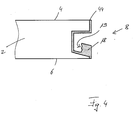
- FIG. 4 shows, can also be produced with the present method, locking elements 18 having undercuts 19, which are open to the inside of the panel 2 out.
- the panels 2 must be erected while performing 3D printing. Although such upright positioning of the panel 2 to be printed is not necessary in the other embodiments shown, it is advantageous. In general, it is advantageous if the portion of the side surface 8 to be printed is aligned upward. With more complicated trained side surface 8, such as by pre-profiling, this can cause the panel 2 is rotated during printing or between two printing operations.
- FIG. 5 shows an enlarged section of the part 44, which is part of the top 4 of the panel 2.
- the sealing material 28 has additives 20 which are arranged in two separate regions, namely once at the lower end and once in the upper region of the sealing material 28.
- This inhomogeneous distribution of the additive 20, made possible by the use of the 3D printer, allows the additives to be optimally applied where they are needed.
- a structure 22 is present, which can also be generated by the 3D printer used. As a result, the haptic impression of this part of the upper side 4 can be influenced.
- FIGS. 6a to 6c show three different embodiments of a panel 2, in which the side surface 8 has a profiling 10 and a locking element 18. All these elements are milled or sawn out of the material of the panel in the embodiments shown Service. A part of the profiling 10 is arranged on a side edge which connects the upper side 4 with the side surface 8. Im in FIG. 6a illustrated embodiment, an L-chamfer 46 was introduced, which was filled with the sealing material 28, that results in a beveled bevel. At the in FIG. 6a not shown, the side surface 8 opposite side surface, a similar structure may be present, so that the two parts, which were prepared with the sealing material 28, form a V-joint.
- FIG. 6b A similar fugue will appear in the FIG. 6b achieved embodiment shown.
- the part of the profiling which is arranged on the side edge between the top 4 and the side surface 8, is in the FIG. 6b a simple beveled bevel 48, which has been coated with the sealing material 28.
- a V-joint is achieved in the laid state of two panels, but significantly less sealing material 28 is used.
- FIG. 6c is again an L-chamfer 46 has been introduced into the side edge between the top 4 and the side surface 8. Unlike in FIG. 6a however, this L-chamfer has not been at least partially filled up by the sealing material 28 so that a chamfered bevel results, but the two side surfaces forming the L-chamfer 46 have been printed with a layer of the sealing material 28. In the laid state of two identical panels, therefore, there is no V-groove, but a rectangular recess or groove.
Abstract
Die Erfindung betrifft ein Verfahren zum Herstellen eines Paneels (2), insbesondere eines Fußbodenpaneels, das eine Oberseite (4), eine der Oberseite (4) gegenüberliegende Unterseite (6) und wenigstens eine Seitenfläche (8) aufweist, dadurch gekennzeichnet, dass die wenigstens eine Seitenfläche (8) wenigstens teilweise mittels eines 3D-Druckers mit einem Versiegelungsmaterial (28) bedruckt wird, wobei ein Teil (44) des Versiegelungsmaterials (28) einen Teil der Oberfläche (4) des Paneels (2) bildet.The invention relates to a method for producing a panel (2), in particular a floor panel, having an upper side (4), a lower side (6) opposite the upper side (4) and at least one side surface (8), characterized in that the at least a side surface (8) is printed at least partially with a sealing material (28) by means of a 3D printer, a portion (44) of the sealing material (28) forming part of the surface (4) of the panel (2).
Description
Die Erfindung betrifft ein Verfahren zum Herstellen eines Paneels, insbesondere eines Fußbodenpaneels, das eine Oberseite, eine der Oberseite gegenüberliegenden Unterseite und wenigstens eine Seitenfläche aufweist. Die Erfindung betrifft zudem eine Vorrichtung zum Durchführen eines derartigen Verfahrens sowie ein durch ein derartiges Verfahren hergestelltes Paneel.The invention relates to a method for producing a panel, in particular a floor panel, which has an upper side, a lower side opposite the upper side and at least one side surface. The invention also relates to an apparatus for carrying out such a method and to a panel produced by such a method.
Fußbodenpaneele in Form eines Laminatfußbodens bilden einen der weltweit am weitesten verbreiteten Bodenbelege. Während ein derartiger Laminatfußboden ursprünglich aus einer Vielzahl von einzelnen Paneelen bestand, die miteinander verleimt werden mussten, hat sich im Stand der Technik die leimlose Verlegung beispielsweise unter dem Begriff "Klicklaminat" durchgesetzt. Bei einer leimlosen Verlegung muss jedoch sichergestellt werden, dass die Paneele im einmal verlegten Zustand auch bei mechanischer Belastung nicht relativ zueinander bewegt werden können, da ansonsten Rillen und Spalten entstehen können. Zudem muss sichergestellt sein, dass durch die im verlegten Zustand vorhandenen kleinen Fugen zwischen einzelnen benachbarten Paneelen eindringende Feuchtigkeit nicht in die Seitenfläche des Paneels eindringen kann, wodurch eine Beschädigung des jeweiligen Paneels hervorgerufen werden würde.Floor panels in the form of a laminate floor form one of the world's most widely used floor coverings. While such a laminate floor originally consisted of a plurality of individual panels which had to be glued together, in the prior art the glueless laying has gained acceptance, for example, by the term "click laminate". In the case of glueless laying, however, it must be ensured that the panels, once installed, can not be moved relative to one another, even under mechanical load, as otherwise grooves and gaps may occur. In addition, it must be ensured that due to the existing in the installed state small joints between individual adjacent panels penetrating moisture can not penetrate into the side surface of the panel, whereby damage to the respective panel would be caused.
Paneele und insbesondere Fußbodenpaneele bestehen in der Regel aus einem Kern, der oftmals aus einer Holzwerkstoffplatte, beispielsweise einer hochdichten Faserplatte (HDF) oder einer mitteldichten Faserplatte (MDF) besteht. Auch andere Holzwerkstoffplatten und Werkstoffe sind als Kern bereits verwendet worden. Auf der Oberseite werden Beschichtungen aufgebracht, die einerseits das optische Erscheinungsbild des Paneels und andererseits Eigenschaften der insbesondere bei Fußbodenpaneelen stark belasteten Oberseite bestimmen. Dies können die Abriebfestigkeit erhöhende Schichten oder andere Schutzschichten sein. Auf der Unterseite werden oftmals ein Gegenzug und gegebenenfalls eine Trittschalldämmung aufgebracht. Oftmals verfügen derartige Fußbodenpaneele an ihren Seitenflächen über Verriegelungselemente, mit denen die Bewegung benachbarter Fußbodenpaneele relativ zueinander im verlegten Zustand verhindert werden soll. Diese werden in der Regel aus dem Kernmaterial des Paneels gefertigt und aus den Seitenflächen der fertigen Paneele herkömmlicherweise herausgefräst. An dieser Stelle eindringende Feuchtigkeit kann zur Beschädigung des Materials und damit zu einer Verringerung der mechanischen Stabilität der Verriegelungselemente führen. Zudem kann es zum Aufquellen des Materials kommen, wodurch der Fußboden auch optisch beeinträchtigt würde.Panels and in particular floor panels usually consist of a core, which often consists of a wood-based panel, for example a high-density fiberboard (HDF) or a medium-density fiberboard (MDF). Also other wood-based panels and materials have already been used as the core. On top of coatings are applied, on the one hand determine the visual appearance of the panel and on the other hand properties of the particular floor panels heavily loaded top. These may be the abrasion resistance enhancing layers or other protective layers. On the underside, a counter-pull and possibly a footfall sound insulation are often applied. Often such floor panels have on their side surfaces on locking elements with which the movement of adjacent floor panels relative to each other in the installed state should be prevented. These are usually made of the core material of the panel and routinely milled out of the side surfaces of the finished panels. Ingress of moisture at this point can damage the material and thus reduce the mechanical stability of the locking elements. In addition, it can lead to swelling of the material, whereby the floor would also be visually impaired.
Durch Fußbodenpaneele können eine Vielzahl unterschiedlicher Fußbodenmaterialien, beispielsweise Stein, Fliesen oder Echtholzfußböden, nachgebildet werden. Dabei ist es wichtig, für den optischen und den haptischen Eindruck des verlegten Fußbodens insbesondere die Fugen zwischen benachbarten Fußbodenelementen möglichst realitätsnah nachzubilden. Dazu werden im Stand der Technik beispielsweise Zusatzelemente in dafür vorgesehene Nuten in der Seitenfläche eingelegt oder eingeklemmt, die einen Teil der Oberfläche bilden und oftmals nur dekorative Aufgaben erfüllen. Zusätzlich muss die Seitenfläche versiegelt werden, was wegen der oftmals strukturierten Seitenfläche, die gegebenenfalls eine Profilierung aufweist, aufwändig und zudem aufgrund von vorhandenen Hinterschneidungen fehleranfällig ist.Through floor panels a variety of different floor materials, such as stone, tiles or real wood floors, can be modeled. It is important to simulate the joints between adjacent floor elements as realistic as possible for the visual and haptic impression of the laid floor in particular. For this purpose, in the prior art, for example, additional elements inserted or clamped in designated grooves in the side surface, which form part of the surface and often only fulfill decorative tasks. In addition, the side surface must be sealed, which is complicated due to the often structured side surface, which optionally has a profiling, and also due to existing undercuts prone to error.
Der Erfindung liegt daher die Aufgabe zu Grunde, ein Verfahren zum Herstellen eines Paneels, insbesondere eines Fußbodenpaneels, so zu verbessern, dass es einfacher und kostengünstiger herstellbar ist und die Möglichkeiten der optischen und haptischen Gestaltung eines Zwischenraums zwischen zwei benachbarten Paneelen erweitert werden.The invention is therefore based on the object to improve a method for producing a panel, in particular a floor panel, so that it is easier and less expensive to produce and the possibilities of optical and haptic design of a gap between two adjacent panels are extended.
Die Erfindung löst die gestellte Aufgabe durch ein Verfahren zum Herstellen eines Paneels, insbesondere eines Fußbodenpaneels, das eine Oberseite, eine der Oberseite gegenüberliegende Unterseite und wenigstens eine Seitenfläche aufweist, wobei sich das Verfahren dadurch auszeichnet, dass die eine Seitenfläche wenigstens teilweise mittels eines 3D-Druckers mit einem Versiegelungsmaterial bedruckt wird, wobei ein Teil des Versiegelungsmaterials einen Teil der Oberfläche des Paneels bildet. In einer bevorzugten Ausgestaltung wird die gesamte Seitenfläche bedruckt.The invention achieves the stated object by a method for producing a panel, in particular a floor panel, which has an upper side, an underside opposite the upper side and at least one side surface, the method being characterized in that the one side surface is at least partially replaced by a 3D panel. Printer is printed with a sealing material, wherein a part of the sealing material forms a part of the surface of the panel. In a preferred embodiment, the entire side surface is printed.
Auf diese Weise ist es besonders einfach möglich, zumindest einen Teil der Seitenfläche, vorteilhafterweise jedoch die gesamte Seitenfläche, des Paneels gegen das Eindringen von Wasser zu versiegeln, sodass beispielsweise auch Fußbodenpaneele für Feuchträume, beispielsweise Badezimmer, herstellbar sind. Zudem wird die Seitenfläche des Paneels mittels des 3D-Druckers wenigstens teilweise entlang der Seitenkante der Seitenfläche bedruckt, sodass ein Teil des aufgebrachten Versiegelungsmaterials einen Teil der Oberfläche des Paneels bildet. Auf diese Weise lässt sich das mittels des 3D-Druckers aufgebrachte Versiegelungsmaterial auch zu dekorativen Zwecken an der Oberseite des Paneels verwenden. Dazu ist es von Vorteil, wenn die Seitenfläche vollständig wenigstens entlang der Seitenkante zur Oberseite des Paneels bedruckt wird. Dies kann jedoch vorzugsweise auch mit unterschiedlichen Materialien geschehen, sodass durch einen auf diese Weise zu erreichenden Materialmix entlang der Seitenkante zwischen der jeweiligen Seitenfläche und der Oberseite des Fußbodenpaneels dekorative Effekte hervorgerufen werden können.In this way, it is particularly easy to seal at least a portion of the side surface, but advantageously the entire side surface of the panel against the ingress of water, so that, for example, floor panels for wet rooms, such as bathrooms, can be produced. In addition, the side surface of the panel is printed by the 3D printer at least partially along the side edge of the side surface so that a portion of the applied sealing material forms part of the surface of the panel. In this way, the sealing material applied by the 3D printer can also be used for decorative purposes on the top of the panel. For this purpose, it is advantageous if the side surface is completely printed at least along the side edge to the top of the panel. However, this can preferably also be done with different materials, so that can be caused by a mixture of materials to be achieved along the side edge between the respective side surface and the top of the floor panel decorative effects.
Natürlich kann die jeweilige Seitenfläche auch entlang der gegenüberliegenden Seitenkante, also der zwischen der Unterseite und der Seitenfläche verlaufenden Seitenkante, vollständig bedruckt werden.Of course, the respective side surface can also be along the opposite side Side edge, so the extending between the bottom and the side surface side edge, are completely printed.
Erfindungsgemäß bildet folglich ein Teil des mittels des 3D-Druckers aufgebrachten Materials einen Teil der Oberseite des Paneels. Dazu wird beispielsweise an der Kante, an der die Seitenfläche mit der Oberseite zusammentrifft, wenigstens eine Schicht des Versiegelungsmaterials mit dem 3D-Drucker aufgetragen. Im verlegten Zustand, in dem zwei Paneele miteinander verbunden sind, ist dieses Material daher sichtbar und kann für dekorative und ästhetische Zwecke verwendet werden. Da es sich bei dem mit dem 3D-Drucker aufgebrachten Versiegelungsmaterial in der Regel um einen anderen Werkstoff handelt, als er für den Rest der Oberseite des Paneels verwendet wird, lassen sich eine Vielzahl unterschiedlicher dekorativer Effekte erzielen.Thus, according to the invention, part of the material applied by means of the 3D printer forms part of the top of the panel. For this purpose, for example, at the edge at which the side surface meets the top, at least one layer of the sealing material is applied with the 3D printer. In the installed state, in which two panels are connected to each other, this material is therefore visible and can be used for decorative and aesthetic purposes. Because the sealing material applied to the 3D printer is typically a different material than that used for the remainder of the top of the panel, a variety of different decorative effects can be achieved.
Vorteilhafterweise wird das Versiegelungsmaterial so aufgedruckt, dass der Teil der Oberfläche des Paneels, der durch das Versiegelungsmaterial gebildet wird, eine Oberflächenstruktur aufweist. Die Erzeugung von Oberflächenstrukturen in dem Bereich der Oberseite, der durch das Versiegelungsmaterial gebildet wird, ist mittels des 3D-Druckers leicht möglich. Auch große und insbesondere tiefe Strukturen lassen sich mittels des 3D-Druckers einfach erzeugen, sodass beispielsweise Fliesenfugen oder Fugen zwischen Steinplatten besonders einfach und realistisch nachgebildet werden können. Durch die für den 3D-Druck verwendeten Materialien können außerdem auch andere Funktionalitäten, wie beispielsweise die elektrische Leitfähigkeit, eine Informationsleitung oder eine Lichtleitung erzeugt werden.Advantageously, the sealing material is printed so that the part of the surface of the panel formed by the sealing material has a surface structure. The creation of surface structures in the area of the top formed by the sealing material is easily possible by means of the 3D printer. Even large and especially deep structures can be easily generated by means of the 3D printer, so that, for example, tile joints or joints between stone slabs can be imitated particularly simply and realistically. The materials used for 3D printing can also be used to create other functionalities, such as electrical conductivity, an information line or a light pipe.
Das aufgedruckte Versiegelungsmaterial, das einen Teil der Oberfläche des Paneels bildet, dient vorteilhafterweise dabei ausschließlich dekorativen Zwecken.The printed sealing material, which forms part of the surface of the panel, advantageously serves exclusively for decorative purposes.
Als vorteilhaft hat sich herausgestellt, wenn die Oberflächenstruktur derart ausgebildet ist, dass im verlegten Zustand zweier Paneele eine Fuge, insbesondere eine Steinfuge, Fliesenfuge oder Parkettfuge, nachgebildet wird.It has proved to be advantageous if the surface structure is such is formed, that in the installed state of two panels a joint, in particular a stone joint, tile joint or parquet joint, is modeled.
In einer bevorzugten Ausgestaltung des Verfahrens wird in die wenigstens eine Seitenfläche eine Profilierung eingebracht, bevor die Seitenfläche mit dem Versiegelungsmaterial bedruckt wird. Vorzugsweise handelt es sich bei der Profilierung um eine Fase und/oder eine Nut und/oder eine Feder und/oder einen modifizierten Falz. Dadurch kann der Materialaufwand für den 3D-Druck reduziert werden, was zu einer weiteren Reduzierung der Herstellungskosten und zu einer Beschleunigung des Verfahrens führt. Da 3D-Drucker das aufzubringende Material in Form einer Vielzahl dünner Schichten aufbringen, ist der Herstellungsaufwand relativ hoch, insbesondere dann, wenn ein relativ großer Anteil der Oberfläche des Paneels durch das Versiegelungsmaterial gebildet werden soll. Werden die Profilierungen in die Seitenfläche eingebracht, können diese sehr einfache Formen, beispielsweise eine einfache Nut oder Feder, beinhalten. Diese sind beispielsweise über Standardfräs- oder Sägewerkzeuge kostengünstig, schnell und genau herstellbar. Natürlich sind auch kompliziertere Profilierungen möglich.In a preferred embodiment of the method, a profiling is introduced into the at least one side surface before the side surface is printed with the sealing material. The profiling is preferably a chamfer and / or a groove and / or a spring and / or a modified fold. As a result, the material costs for the 3D printing can be reduced, which leads to a further reduction of the production costs and to an acceleration of the method. Since 3D printers apply the material to be applied in the form of a multiplicity of thin layers, the production outlay is relatively high, in particular if a relatively large proportion of the surface of the panel is to be formed by the sealing material. If the profilings are introduced into the side surface, they can contain very simple shapes, for example a simple tongue or groove. These are cost-effective, for example standard milling or sawing tools, fast and accurate to produce. Of course, more complicated profiles are possible.
Vorteilhafterweise ist an der wenigstens einen Seitenfläche ein Verriegelungselement angeordnet, das zumindest teilweise mittels des 3D-Druckers aufgedruckt wird. Da das Verriegelungselement zumindest teilweise aufgedruckt wird, kommt es hier zu einer ausreichend festen und stabilen Verbindung zwischen beispielsweise dem Kernmaterial des Paneels, das einen Teil der zu bedruckenden Seitenfläche bildet, und dem aufgedruckten Verriegelungselement aus dem Versiegelungsmaterial oder einem anderen Material. Natürlich können auch unterschiedliche Materialien verwendet werden. Gleichzeitig kann für das Verriegelungselement ein Material gewählt werden, das nicht gleichzeitig das Material des Kerns des Paneels ist. Auf diese Weise ist es möglich, das Kernmaterial des Paneels auf die geforderten Eigenschaften hin zu optimieren und gleichzeitig Verriegelungselemente bereitzustellen, die andere Eigenschaften aufweisen und auf die Bedürfnisse bei Verriegelungselementen optimiert sind. Auf diese Weise werden Verriegelungselemente aus einer Vielzahl dünner Schichten aufgebaut. Es ist daher nicht nötig, die Verriegelungselemente, wie dies im Stand der Technik bekannt ist, aus dem eigentlichen Paneel beziehungsweise dessen Kernmaterial herauszusägen oder herauszufräsen. Die damit verbundenen Einschränkungen der möglichen Strukturen, Richtungen und Werkzeuge sind beim Verfahren gemäß diesem Ausführungsbeispiel der vorliegenden Erfindung nicht mehr vorhanden. Durch das Aufdrucken der Verriegelungselemente durch den 3D-Drucker lassen sich auch komplizierteste Profile für einzelne Verriegelungselemente, beispielsweise mit Hinterschneidungen, realisieren, sodass neben dem für die Anforderungen von Verriegelungselementen optimierten Material auch beispielsweise bezüglich der Auszugfestigkeit optimierte oder verbesserte Profile verwendet werden können.Advantageously, a locking element is arranged on the at least one side surface, which is at least partially printed by means of the 3D printer. Since the locking element is at least partially printed, it comes here to a sufficiently strong and stable connection between, for example, the core material of the panel, which forms part of the side surface to be printed, and the printed locking element of the sealing material or other material. Of course, different materials can be used. At the same time, a material can be chosen for the locking element, which is not the material of the core of the panel at the same time. In this way it is possible to optimize the core material of the panel to the required properties and at the same time to provide locking elements that have different properties and optimized to the needs of locking elements. In this way, locking elements are constructed from a plurality of thin layers. It is therefore not necessary to cut or mill out the locking elements, as is known in the art, from the actual panel or its core material. The associated limitations of the possible structures, directions and tools are no longer present in the method according to this embodiment of the present invention. By printing the locking elements by the 3D printer, even the most complicated profiles for individual locking elements, for example with undercuts, can be realized so that in addition to the material optimized for the requirements of locking elements, optimized or improved profiles can also be used, for example with regard to the pull-out strength.
In einer bevorzugten Ausgestaltung verfügt das Paneel, insbesondere das Fußbodenpaneel, beispielsweise über einen Kern aus einem leichten Holzwerkstoff. Bei diesem ist gegenüber den bisher zu verwendenden dichten und hochdichten Faserplatten der Leimanteil reduziert, wodurch neben dem Gewicht auch die Herstellungskosten reduziert werden können. Diese Paneele sind für den Endanwender folglich einfacher und leichter zu handhaben, sind leichter zu transportieren und weisen bessere Eigenschaften aufgrund der gegebenenfalls höheren Elastizität auf.In a preferred embodiment, the panel, in particular the floor panel, for example, has a core of a light wood material. In this case, compared with the hitherto used dense and high-density fibreboard, the amount of glue is reduced, whereby not only the weight but also the production costs can be reduced. Consequently, these panels are easier and easier to handle for the end user, are easier to transport and have better properties due to the possibly higher elasticity.
Vorteilhafterweise werden an wenigstens zwei einander gegenüberliegenden Seitenflächen zueinander korrespondierende Verriegelungselemente jeweils wenigstens teilweise mittels eines 3D-Druckers auf der jeweiligen Seitenfläche aufgedruckt. Natürlich können einzelne oder alle Verriegelungselemente auch vollständig durch den 3D-Drucker aufgebracht werden. Dies ist insbesondere unabhängig davon, auf wie vielen Seitenflächen Verriegelungselemente aufgebracht werden sollen. Insbesondere falls an gegenüberliegenden Seitenflächen die Verriegelungselemente mit dem 3D-Drucker aufgedruckt werden, ist es möglich, die einzelnen Profile besonders genau aufeinander abzustimmen. Es ist nicht mehr nötig, für unterschiedliche Profile der einzelnen Verriegelungselemente unterschiedliche Werkzeuge vorzuhalten, die möglichst exakt in die jeweilige Werkzeugmaschine eingesetzt und insbesondere möglichst exakt relativ zum eigentlichen Paneel ausgerichtet werden müssen. Vielmehr ist es beispielsweise möglich, die Position des Paneels beispielsweise durch Marleirungen an einer Seite des Paneels zu erfassen und beispielsweise einen Druckkopf des 3D-Druckers anhand der dadurch erfassten oder ermittelbaren Position der Seitenfläche des Paneels auszurichten. Auch dadurch werden das Herstellungsverfahren beschleunigt und die Herstellungskosten gesenkt.Advantageously, on at least two mutually opposite side surfaces mutually corresponding locking elements are each at least partially printed by means of a 3D printer on the respective side surface. Of course, individual or all locking elements can also be completely applied by the 3D printer. This is particularly independent of how many side surfaces locking elements are to be applied. In particular, if on opposite side surfaces, the locking elements are printed with the 3D printer, it is It is possible to coordinate the individual profiles very precisely. It is no longer necessary to provide for different profiles of the individual locking elements different tools that must be used as accurately as possible in the respective machine tool and in particular must be aligned as accurately as possible relative to the actual panel. Rather, it is for example possible to detect the position of the panel, for example by Marleirungen on one side of the panel and align, for example, a print head of the 3D printer on the basis of the detected or determinable position of the side surface of the panel. Also, this speeds up the manufacturing process and reduces manufacturing costs.
Vorzugsweise sind die beiden korrespondierenden Verriegelungselemente ausgebildet, zwei identische Paneele, insbesondere Fußbodenpaneele, miteinander zu verbinden und in wenigstens eine, bevorzugt wenigstens zwei Raumrichtungen relativ zueinander zu verriegeln. Derartige Profile sind bereits bekannt. Die Verriegelung entlang einer Richtung bedeutet, dass eine Bewegung der beiden Paneele relativ zueinander in dieser Richtung nicht mehr möglich ist. Aus dem Stand der Technik sind beispielsweise Profile für Verriegelungselemente bekannt, bei denen die einzelnen Paneele beispielsweise in einer Richtung senkrecht zur Oberseite der unterschiedlichen Paneele und in einer Richtung senkrecht zur Seitenfläche der Paneele, entlang derer die beiden Paneele miteinander verbunden sind, nicht mehr verschoben werden können. Eine Verschiebung der Paneele relativ zueinander entlang der Seitenfläche ist jedoch beispielsweise weiterhin möglich.Preferably, the two corresponding locking elements are designed to connect two identical panels, in particular floor panels, to one another and to lock them in at least one, preferably at least two spatial directions relative to one another. Such profiles are already known. The locking along one direction means that a movement of the two panels relative to each other in this direction is no longer possible. For example, profiles for locking elements are known from the prior art, in which the individual panels are no longer displaced in a direction perpendicular to the top of the different panels and in a direction perpendicular to the side surface of the panels, along which the two panels are interconnected can. However, displacement of the panels relative to each other along the side surface is still possible, for example.
Da vorzugsweise das Aufbringen der Verriegelungselemente im gleichen Arbeitsschritt wie das Aufbringen des Versiegelungsmaterials und damit des Herstellens des Teils der Oberfläche geschieht, ist anders als bei Verfahren aus dem Stand der Technik, in denen die Versiegelung einen separaten Arbeitsschritt bedeutet, das Verfahren weiterhin in ökonomisch sinnvollerweise durchzuführen. Insbesondere für den Fall, dass die zu verwendenden Verriegelungsprofile über massive Anteile verfügen, können diese weiterhin aus dem Material des Paneels, beispielsweise des Kerns, hergestellt werden. Dies geschieht vorteilhafterweise, indem die entsprechende Profilierung in die Seitenfläche des Paneels eingebracht wird.Since preferably the application of the locking elements in the same step as the application of the sealing material and thus the production of the part of the surface happens, unlike in the prior art, in which the seal means a separate step, the method continues in an economically sensible way perform. Especially in the event that the locking profiles to be used have massive proportions, they can continue to be made of the material of the panel, for example the core. This is advantageously done by the corresponding profiling is introduced into the side surface of the panel.
In einer bevorzugten Ausgestaltung werden mehrere verschiedene Versiegelungsmaterialien aufgedruckt. Dabei können unterschiedliche 3D-Drucker oder ein 3D-Drucker mit unterschiedlichen Druckköpfen verwendet werden. Prinzipiell ist es natürlich auch möglich, den gleichen Druckkopf eines 3D-Druckers für unterschiedliche Materialien zu verwenden. Die Verwendung unterschiedlicher Materialien erlaubt es, die unterschiedlichen Funktionen, die durch die aufgebrachte Materialschicht erfüllt werden sollen, optimal zu erfüllen und so beispielsweise die Festigkeits-, Elastizitäts- und Stabilitätseigenschaften einerseits und die optischen und gegebenenfalls weiteren physikalischen und/oder chemischen Eigenschaften andererseits an die jeweils benötigten Anforderungen anzupassen. Dadurch werden die Flexibilität des Verfahrens und die Vielfalt der möglichen herzustellenden Paneele gesteigert.In a preferred embodiment, several different sealing materials are printed. Different 3D printers or a 3D printer with different print heads can be used. In principle, it is of course also possible to use the same print head of a 3D printer for different materials. The use of different materials makes it possible to optimally fulfill the different functions which are to be fulfilled by the applied material layer and thus, for example, the strength, elasticity and stability properties on the one hand and the optical and optionally further physical and / or chemical properties on the other to adapt to each required requirements. This increases the flexibility of the process and the variety of possible panels to be produced.
Bevorzugt weist zumindest ein Teil des Versiegelungsmateriales, der einen Teil der Oberseite des Paneels bildet, wenigstens ein Additiv auf. Beispielhaft seien Korund, Farben und/oder Pigmente, antibakteriell wirkende Substanzen, Glas, insbesondere in Form von Kugeln und/oder Hohlkugeln, und/oder Fasern, beispielsweise aus Cellulose, Glas oder Carbon genannt. Als antibakteriell wirkende Substanzen kann beispielsweise Silber verwendet werden. Die Verwendung von Korund, Glaskugeln und/oder Glashohlkugeln zur Verbesserung des Widerstandes der Oberfläche gegen Abrieb ist aus dem Stand der Technik bekannt. Fasern, die beispielsweise aus Cellulose, Glas oder Carbon bestehen können, werden zur Armierung und/oder zur Ableitung elektrostatischer Aufladungen verwendet. Farben und/oder Pigmente können als zusätzliche optische Gestaltungsoptionen zusätzlich zu dem sich bereits auf der Oberfläche des Paneels befindenden Dekors verwendet werden.Preferably, at least a portion of the sealing material forming part of the top of the panel comprises at least one additive. Examples are corundum, dyes and / or pigments, antibacterial substances, glass, in particular in the form of spheres and / or hollow spheres, and / or fibers, for example of cellulose, glass or carbon called. As antibacterial substances, for example, silver can be used. The use of corundum, glass beads and / or glass hollow spheres to improve the resistance of the surface to abrasion is known from the prior art. Fibers, which may be cellulose, glass or carbon, for example, are used to reinforce and / or dissipate electrostatic charges. Inks and / or pigments may be used as additional optical design options in addition to the decor already on the surface of the panel.
Besonders bevorzugt wird das wenigstens eine Additiv inhomogen in der Nutzschicht verteilt. Da die Additive völlig unterschiedliche Aufgaben lösen können und unterschiedliche Eigenschaften aufweisen, sind nicht alle Additive in dem gesamten aufgebrachten Versiegelungsmaterial oder gegebenenfalls vorhandenen anderen aufgebrachten Materialien nötig. So sind beispielsweise Korund und/oder Glaskugeln zur Verbesserung des Widerstandes gegen Abrieb insbesondere nahe der Oberfläche der aufzubringenden Schicht von Interesse. In tiefer liegenden Regionen sind sie dagegen nur bedingt sinnvoll. Bei dem bisher aus dem Stand der Technik bekannten Auftragungsverfahren von derartigen Beschichtungen lässt sich eine inhomogene Verteilung der einzelnen Additive nicht kontrolliert erreichen, da vorgefertigtes Auftragsmaterial, das alle Additive enthalten muss, die in einer Oberflächenschicht benötigt werden, vollflächig aufgebracht wird. Durch die besondere Ausgestaltung des vorliegenden Verfahrens können nun anforderungsoptimal die einzelnen Additive verwendet werden. Dadurch wird die Menge der benötigten Additive reduziert, wodurch auch die Herstellungskosten sinken.Particularly preferably, the at least one additive is distributed inhomogeneously in the wear layer. Since the additives can perform completely different tasks and have different properties, not all additives are needed in the entire applied sealing material or any other applied materials applied. For example, corundum and / or glass beads are of interest for improving the resistance to abrasion, in particular near the surface of the layer to be applied. In lower regions, on the other hand, they only make limited sense. In the previously known from the prior art application method of such coatings, an inhomogeneous distribution of the individual additives can not be controlled, since prefabricated application material, which must contain all additives that are required in a surface layer is applied over the entire surface. Due to the particular embodiment of the present method, the individual additives can now be used optimally in accordance with requirements. As a result, the amount of additives required is reduced, which also reduces the production costs.
Die Reduzierung der verwendeten Additivmengen hat zudem zur Folge, dass das Recycling der auf diese Weise hergestellten Paneele nach Gebrauchsende ressourcenschonend möglich ist und zudem Produkteigenschaften erreicht werden können, die bisher als unvereinbar galten.The reduction in the amount of additive used also has the consequence that the recycling of the panels produced in this way after use is resource-saving and also product properties can be achieved, which were previously considered incompatible.
Vorzugsweise wird das gesamte Versiegelungsmaterial in einem einzelnen Arbeitsschritt aufgebracht. Dies kann beispielsweise durch mehrere Druckköpfe eines einzelnen 3D-Druckers geschehen, die mit unterschiedlichen Materialien und/oder unterschiedlichen Additiven, befüllt werden.Preferably, the entire sealing material is applied in a single operation. This can be done for example by a plurality of print heads of a single 3D printer, which are filled with different materials and / or different additives.
Vorteilhafterweise wird zum Aufdrucken des wenigstens einen Versiegelungsmaterials wenigstens ein thermoplastischer Kunststoff und/oder wenigstens ein strahlenhärtbarer Lack verwendet. So kann der 3D-Drucker beispielsweise nach dem "fused deposition modelling" Verfahren funktionieren, bei dem aufgeschmolzene Thermoplaste schichtweise aufgetragen werden. Alternativ dazu kann auch ein 3D-Drucker nach dem "multijet modelling" Verfahren verwendet werden, bei den härtbaren Lacken, die beispielsweise durch UV-Strahlung oder Elektronenstrahlung gehärtet werden können, gearbeitet wird. Unabhängig von der Art des Materials können verschiedenste Eigenschaften durch Variationen der Produkte angepasst werden. Natürlich kann es sinnvoll sein, unterschiedliche Materialien für die unterschiedlichen Funktionen aufzubringen. So ist es denkbar, zunächst ein erstes Versiegelungsmaterial aufzubringen, das für eine Versiegelung der jeweiligen Seitenfläche gegen das Eindringen beispielsweise von Wasser, sorgt. Auf diese so aufgebrachten Teilschichten können weitere Schichten aufgebracht werden, die weitere dekorative Effekte in dem durch das Material gebildeten Teil der Oberfläche des Paneels bilden und/oder ein Verriegelungselement bilden.Advantageously, at least one thermoplastic and / or at least one radiation-curable lacquer is used to print the at least one sealing material. For example, the 3D printer can operate according to the "fused deposition modeling" method in which molten thermoplastics are applied in layers. Alternatively, a 3D printer according to the "multijet modeling" method can be used, in the curable coatings, which can be cured, for example, by UV radiation or electron radiation, is used. Regardless of the type of material, various properties can be adapted through variations of the products. Of course, it may be useful to apply different materials for the different functions. Thus, it is conceivable first to apply a first sealing material, which ensures a sealing of the respective side surface against the penetration of, for example, water. On these sublayers applied in this way, further layers can be applied which form further decorative effects in the part of the surface of the panel formed by the material and / or form a locking element.
So kann beispielsweise ein Anteil des Verriegelungselementes elastischer ausgebildet sein als ein benachbarter Anteil, sodass beispielsweise beim Verbinden der Paneele das Verriegelungselement an dieser Stelle zusammengedrückt werden kann. Nachdem die einzelnen Paneele in ihre endgültigen Positionen gebracht wurden, kann das so zusammengedrückte Verriegelungselement entspannen und beispielsweise in eine dafür vorgesehene Hinterschneidung einschnappen. Anders als bei Verriegelungselementen aus dem Stand der Technik, die vollständig aus dem gleichen Material bestehen, ist es auf diese Weise möglich, die besonders belasteten Bereiche der Verriegelungselemente besonders elastisch auszubilden und somit ein Abbrechen zu vermeiden.Thus, for example, a portion of the locking element can be made more elastic than an adjacent portion, so that, for example, when connecting the panels, the locking element can be compressed at this point. After the individual panels have been brought into their final positions, the thus compressed locking element can relax and snap, for example, in a designated undercut. Unlike locking elements of the prior art, which are made entirely of the same material, it is possible in this way to form the particularly loaded areas of the locking elements particularly elastic and thus to avoid breakage.
Vorzugsweise wird das Paneel mit der durch den 3D-Drucker zu bedruckenden Seitenfläche nach oben angeordnet. Auf diese Weise kann das durch den Drucker aufgebrachte Material der Schwerkraft folgend aufgebracht werden und ein Zerfließen oder Verschmieren im noch nicht ausgehärteten Zustand wird weitestgehend oder sogar vollständig verhindert. Werden unterschiedliche Seitenflächen mit wenigstens einem 3D-Drucker beschichtet, ist es von Vorteil, die jeweils zu bedruckende Seitenfläche nach oben auszurichten und somit das Paneel zwischen einzelnen Druckvorgängen auf den unterschiedlichen Seitenflächen zu drehen.Preferably, the panel with the side surface to be printed by the 3D printer is arranged upward. In this way, the material applied by the printer can be gravitationally applied and a bleed or smear in the uncured state as far as possible or even completely prevented. If different side surfaces are coated with at least one 3D printer, it is advantageous to align the respective side surface to be printed upwards and thus to rotate the panel between individual printing processes on the different side surfaces.
Die Erfindung löst die gestellte Aufgabe zudem durch eine Vorrichtung zum Durchführen eines hier beschriebenen Verfahrens, die wenigstens einen 3D-Drucker zum Aufdrucken wenigstens eines Teils des wenigstens einen Versiegelungsmaterials aufweist. Vorteilhafterweise verfügt der wenigstens eine 3D-Drucker über wenigstens zwei Druckköpfe, durch die unterschiedliche Materialien aufgedruckt werden können. Derartige 3D-Drucker sind aus dem Stand der Technik prinzipiell bekannt. Vorzugsweise verfügt die Vorrichtung zudem über eine Profilierungseinrichtung zum Einbringen einer Profilierung in wenigstens eine Seitenfläche eines Paneels. Auf diese Weise lässt sich zunächst die Profilierung einbringen, wobei die unterschiedlichen Anteile des so eingebrachten Profils anschließend mit dem Versiegelungsmaterial bedruckt werden können.The invention also achieves the stated object by a device for carrying out a method described here, which has at least one 3D printer for printing on at least one part of the at least one sealing material. Advantageously, the at least one 3D printer has at least two print heads through which different materials can be printed. Such 3D printers are known in principle from the prior art. Preferably, the device also has a profiling device for introducing a profiling in at least one side surface of a panel. In this way, the profiling can first be introduced, wherein the different proportions of the profile thus introduced can subsequently be printed with the sealing material.
Die Erfindung löst die gestellte Aufgabe zudem durch ein Paneel, insbesondere ein Fußbodenpaneel, das durch eines der hier beschriebenen Verfahren herstellbar ist.The invention solves this problem by a panel, in particular a floor panel, which can be produced by one of the methods described herein.
Mit Hilfe der beiliegenden Figuren werden nachfolgend Ausführungsbeispiele der vorliegenden Erfindung näher erläutert. Es zeigt:
- Figur 1a und 1b -
- zwei Paneele gemäß Ausführungsformen der vorliegenden Erfindung,
- Figur 2 -
- eine weitere Ausführungsform eines Paneels,
- Figur 3 -
- unterschiedliche Stadien während des Verbindens zweiter Paneele,
- Figur 4 -
- eine weitere Ausführungsform eines Paneels,
- Figur 5 -
- einen vergrößerten Ausschnitt aus der Oberseite eines Paneels und
- Figuren 6a bis 6c -
- weitere Ausführungsformen eines Paneels.
- FIGS. 1a and 1b
- two panels according to embodiments of the present invention,
- FIG. 2 -
- another embodiment of a panel,
- FIG. 3 -
- different stages during the joining of second panels,
- FIG. 4 -
- another embodiment of a panel,
- FIG. 5 -
- an enlarged section of the top of a panel and
- FIGS. 6a to 6c
- further embodiments of a panel.
Während im in
Im in
Im unteren Bereich der
Wie
Die
Eine ähnliche Fuge wird im in
In
Man erkennt bei den drei gezeigten Ausführungsbeispielen in den
- 22
- Paneelpaneling
- 44
- Oberseitetop
- 66
- Unterseitebottom
- 88th
- Seitenflächeside surface
- 1010
- Profilierungprofiling
- 1212
- Nutgroove
- 1414
- kurzer Schenkelshort thigh
- 1616
- langer Schenkellong thigh
- 1818
- Verriegelungselementlocking element
- 1919
- Hinterschneidungundercut
- 2020
- Additivadditive
- 2222
- Strukturstructure
- 2828
- Versiegelungsmaterialsealing material
- 3636
- erster Anteilfirst share
- 3838
- zweiter Anteilsecond share
- 4040
- dritter Anteilthird share
- 4242
- Nasenose
- 4444
- Teilpart
- 4646
- L-FaseL-bevel
- 4848
- Fasechamfer
Claims (15)
Priority Applications (2)
| Application Number | Priority Date | Filing Date | Title |
|---|---|---|---|
| PL15001461T PL2955296T3 (en) | 2014-06-12 | 2015-05-15 | Method for manufacturing a panel and panel |
| EP15001461.1A EP2955296B1 (en) | 2014-06-12 | 2015-05-15 | Method for manufacturing a panel and panel |
Applications Claiming Priority (2)
| Application Number | Priority Date | Filing Date | Title |
|---|---|---|---|
| EP14002024.9A EP2955295B1 (en) | 2014-06-12 | 2014-06-12 | Method for manufacturing a panel |
| EP15001461.1A EP2955296B1 (en) | 2014-06-12 | 2015-05-15 | Method for manufacturing a panel and panel |
Publications (2)
| Publication Number | Publication Date |
|---|---|
| EP2955296A1 true EP2955296A1 (en) | 2015-12-16 |
| EP2955296B1 EP2955296B1 (en) | 2018-03-21 |
Family
ID=50943026
Family Applications (2)
| Application Number | Title | Priority Date | Filing Date |
|---|---|---|---|
| EP14002024.9A Active EP2955295B1 (en) | 2014-06-12 | 2014-06-12 | Method for manufacturing a panel |
| EP15001461.1A Active EP2955296B1 (en) | 2014-06-12 | 2015-05-15 | Method for manufacturing a panel and panel |
Family Applications Before (1)
| Application Number | Title | Priority Date | Filing Date |
|---|---|---|---|
| EP14002024.9A Active EP2955295B1 (en) | 2014-06-12 | 2014-06-12 | Method for manufacturing a panel |
Country Status (4)
| Country | Link |
|---|---|
| EP (2) | EP2955295B1 (en) |
| ES (2) | ES2664105T3 (en) |
| PL (2) | PL2955295T3 (en) |
| PT (2) | PT2955295T (en) |
Cited By (4)
| Publication number | Priority date | Publication date | Assignee | Title |
|---|---|---|---|---|
| EP3611312A1 (en) * | 2018-08-16 | 2020-02-19 | Zhejiang Jingtong Plastics Co., Ltd. | Chamfered plastic floor |
| DE102019117425A1 (en) * | 2019-06-27 | 2020-12-31 | Guido Schulte | Plate-shaped component and method for its manufacture |
| DE102019117426A1 (en) * | 2019-06-27 | 2020-12-31 | Guido Schulte | Plate-shaped component |
| CN113502999A (en) * | 2021-07-28 | 2021-10-15 | 广州海鸥住宅工业股份有限公司 | Concatenation formula 3D prints waterproof chassis |
Families Citing this family (3)
| Publication number | Priority date | Publication date | Assignee | Title |
|---|---|---|---|---|
| AT518080B1 (en) * | 2015-11-30 | 2017-07-15 | Greiner Perfoam Gmbh | Method for producing a motor vehicle interior component |
| AT518085B1 (en) * | 2015-11-30 | 2017-07-15 | Greiner Perfoam Gmbh | Method for producing a motor vehicle interior component |
| DE102016115886A1 (en) | 2016-08-26 | 2018-03-01 | Guido Schulte | Plate-shaped component |
Citations (4)
| Publication number | Priority date | Publication date | Assignee | Title |
|---|---|---|---|---|
| WO2002060691A1 (en) * | 2001-01-31 | 2002-08-08 | Pergo Ab | A process for the manufacturing of joining profiles |
| DE202011109396U1 (en) * | 2011-12-22 | 2012-01-26 | Jörg Paetrow | Plate-shaped elements for covering surfaces |
| WO2014011110A1 (en) * | 2012-07-13 | 2014-01-16 | Floor Iptech Ab | Method of coating a building panel with digital printing/coating technique |
| US20140017452A1 (en) * | 2012-07-13 | 2014-01-16 | Floor Iptech Ab | Digital coating and printing |
-
2014
- 2014-06-12 EP EP14002024.9A patent/EP2955295B1/en active Active
- 2014-06-12 PL PL14002024T patent/PL2955295T3/en unknown
- 2014-06-12 ES ES14002024.9T patent/ES2664105T3/en active Active
- 2014-06-12 PT PT140020249T patent/PT2955295T/en unknown
-
2015
- 2015-05-15 PL PL15001461T patent/PL2955296T3/en unknown
- 2015-05-15 ES ES15001461.1T patent/ES2669437T3/en active Active
- 2015-05-15 PT PT150014611T patent/PT2955296T/en unknown
- 2015-05-15 EP EP15001461.1A patent/EP2955296B1/en active Active
Patent Citations (4)
| Publication number | Priority date | Publication date | Assignee | Title |
|---|---|---|---|---|
| WO2002060691A1 (en) * | 2001-01-31 | 2002-08-08 | Pergo Ab | A process for the manufacturing of joining profiles |
| DE202011109396U1 (en) * | 2011-12-22 | 2012-01-26 | Jörg Paetrow | Plate-shaped elements for covering surfaces |
| WO2014011110A1 (en) * | 2012-07-13 | 2014-01-16 | Floor Iptech Ab | Method of coating a building panel with digital printing/coating technique |
| US20140017452A1 (en) * | 2012-07-13 | 2014-01-16 | Floor Iptech Ab | Digital coating and printing |
Cited By (5)
| Publication number | Priority date | Publication date | Assignee | Title |
|---|---|---|---|---|
| EP3611312A1 (en) * | 2018-08-16 | 2020-02-19 | Zhejiang Jingtong Plastics Co., Ltd. | Chamfered plastic floor |
| DE102019117425A1 (en) * | 2019-06-27 | 2020-12-31 | Guido Schulte | Plate-shaped component and method for its manufacture |
| DE102019117426A1 (en) * | 2019-06-27 | 2020-12-31 | Guido Schulte | Plate-shaped component |
| CN113502999A (en) * | 2021-07-28 | 2021-10-15 | 广州海鸥住宅工业股份有限公司 | Concatenation formula 3D prints waterproof chassis |
| CN113502999B (en) * | 2021-07-28 | 2022-06-10 | 广州海鸥住宅工业股份有限公司 | Concatenation formula 3D prints waterproof chassis |
Also Published As
| Publication number | Publication date |
|---|---|
| PT2955295T (en) | 2018-05-02 |
| ES2669437T3 (en) | 2018-05-25 |
| PL2955296T3 (en) | 2018-08-31 |
| EP2955295A1 (en) | 2015-12-16 |
| EP2955295B1 (en) | 2018-02-28 |
| PL2955295T3 (en) | 2018-07-31 |
| EP2955296B1 (en) | 2018-03-21 |
| ES2664105T3 (en) | 2018-04-18 |
| PT2955296T (en) | 2018-05-16 |
Similar Documents
| Publication | Publication Date | Title |
|---|---|---|
| EP2955296B1 (en) | Method for manufacturing a panel and panel | |
| EP1559850B1 (en) | Panel, in particular flooring panel | |
| DE60209930T2 (en) | FLOORING | |
| EP2586929B1 (en) | Floor lining | |
| DE60015603T3 (en) | METHOD FOR PRODUCING FLOOR ELEMENTS | |
| EP1593795B1 (en) | Process and apparatus for manufacturing flat elements, in particular flooring elements | |
| AT517360B1 (en) | parquet board | |
| DE102009022483A1 (en) | Set of panels, in particular floor panels | |
| EP1357239A2 (en) | Floor plate | |
| DE20300291U1 (en) | floor panel | |
| EP1808311A1 (en) | Panel, particularly a floor panel | |
| DE202019103690U1 (en) | paneling | |
| EP1683929A2 (en) | Method of producing a panel, in particular flooring panel, and panel, in particular flooring panel | |
| DE102007061035A1 (en) | Cladding panel and cladding therefrom | |
| EP3234280B1 (en) | Panel and panel assembly comprising a plurality of such panels | |
| WO2006063579A1 (en) | Panel with multi-layered construction | |
| DE102009040114A1 (en) | Panel for the formation of a covering and method for the production of such a panel | |
| EP2664730A1 (en) | Panel for laying in an area as cladding or lining with improved moisture resistance | |
| DE202008001822U1 (en) | Floor plate with stone surface | |
| DE10154767B4 (en) | floor panel | |
| DE10256501A1 (en) | Flooring panel of wood material has angled edges and/or interlocking elements along its longitudinal side edges provided with lacquer coating | |
| EP2918747A1 (en) | Panel with chamfer sealed using a superabsorber and method for manufacturing the same | |
| WO2006074706A1 (en) | Component, in particular panel and corresponding structural part | |
| DE102016115845A1 (en) | Method for producing a cladding for a building | |
| DE202013104859U1 (en) | Laying element with connecting means |
Legal Events
| Date | Code | Title | Description |
|---|---|---|---|
| PUAI | Public reference made under article 153(3) epc to a published international application that has entered the european phase |
Free format text: ORIGINAL CODE: 0009012 |
|
| AK | Designated contracting states |
Kind code of ref document: A1 Designated state(s): AL AT BE BG CH CY CZ DE DK EE ES FI FR GB GR HR HU IE IS IT LI LT LU LV MC MK MT NL NO PL PT RO RS SE SI SK SM TR |
|
| AX | Request for extension of the european patent |
Extension state: BA ME |
|
| 17P | Request for examination filed |
Effective date: 20160520 |
|
| RBV | Designated contracting states (corrected) |
Designated state(s): AL AT BE BG CH CY CZ DE DK EE ES FI FR GB GR HR HU IE IS IT LI LT LU LV MC MK MT NL NO PL PT RO RS SE SI SK SM TR |
|
| RAP1 | Party data changed (applicant data changed or rights of an application transferred) |
Owner name: FLOORING TECHNOLOGIES LTD. |
|
| GRAJ | Information related to disapproval of communication of intention to grant by the applicant or resumption of examination proceedings by the epo deleted |
Free format text: ORIGINAL CODE: EPIDOSDIGR1 |
|
| GRAP | Despatch of communication of intention to grant a patent |
Free format text: ORIGINAL CODE: EPIDOSNIGR1 |
|
| STAA | Information on the status of an ep patent application or granted ep patent |
Free format text: STATUS: REQUEST FOR EXAMINATION WAS MADE |
|
| GRAP | Despatch of communication of intention to grant a patent |
Free format text: ORIGINAL CODE: EPIDOSNIGR1 |
|
| STAA | Information on the status of an ep patent application or granted ep patent |
Free format text: STATUS: GRANT OF PATENT IS INTENDED |
|
| RIC1 | Information provided on ipc code assigned before grant |
Ipc: B33Y 80/00 20150101ALI20171020BHEP Ipc: E04F 15/02 20060101AFI20171020BHEP |
|
| INTG | Intention to grant announced |
Effective date: 20171115 |
|
| GRAS | Grant fee paid |
Free format text: ORIGINAL CODE: EPIDOSNIGR3 |
|
| GRAA | (expected) grant |
Free format text: ORIGINAL CODE: 0009210 |
|
| STAA | Information on the status of an ep patent application or granted ep patent |
Free format text: STATUS: THE PATENT HAS BEEN GRANTED |
|
| AK | Designated contracting states |
Kind code of ref document: B1 Designated state(s): AL AT BE BG CH CY CZ DE DK EE ES FI FR GB GR HR HU IE IS IT LI LT LU LV MC MK MT NL NO PL PT RO RS SE SI SK SM TR |
|
| REG | Reference to a national code |
Ref country code: GB Ref legal event code: FG4D Free format text: NOT ENGLISH |
|
| REG | Reference to a national code |
Ref country code: CH Ref legal event code: EP |
|
| REG | Reference to a national code |
Ref country code: AT Ref legal event code: REF Ref document number: 981267 Country of ref document: AT Kind code of ref document: T Effective date: 20180415 |
|
| REG | Reference to a national code |
Ref country code: IE Ref legal event code: FG4D Free format text: LANGUAGE OF EP DOCUMENT: GERMAN |
|
| REG | Reference to a national code |
Ref country code: DE Ref legal event code: R096 Ref document number: 502015003489 Country of ref document: DE |
|
| REG | Reference to a national code |
Ref country code: CH Ref legal event code: NV Representative=s name: BRAUNPAT BRAUN EDER AG, CH |
|
| REG | Reference to a national code |
Ref country code: FR Ref legal event code: PLFP Year of fee payment: 4 Ref country code: PT Ref legal event code: SC4A Ref document number: 2955296 Country of ref document: PT Date of ref document: 20180516 Kind code of ref document: T Free format text: AVAILABILITY OF NATIONAL TRANSLATION Effective date: 20180510 |
|
| REG | Reference to a national code |
Ref country code: ES Ref legal event code: FG2A Ref document number: 2669437 Country of ref document: ES Kind code of ref document: T3 Effective date: 20180525 |
|
| REG | Reference to a national code |
Ref country code: SE Ref legal event code: TRGR |
|
| PG25 | Lapsed in a contracting state [announced via postgrant information from national office to epo] |
Ref country code: NO Free format text: LAPSE BECAUSE OF FAILURE TO SUBMIT A TRANSLATION OF THE DESCRIPTION OR TO PAY THE FEE WITHIN THE PRESCRIBED TIME-LIMIT Effective date: 20180621 Ref country code: FI Free format text: LAPSE BECAUSE OF FAILURE TO SUBMIT A TRANSLATION OF THE DESCRIPTION OR TO PAY THE FEE WITHIN THE PRESCRIBED TIME-LIMIT Effective date: 20180321 Ref country code: LT Free format text: LAPSE BECAUSE OF FAILURE TO SUBMIT A TRANSLATION OF THE DESCRIPTION OR TO PAY THE FEE WITHIN THE PRESCRIBED TIME-LIMIT Effective date: 20180321 Ref country code: HR Free format text: LAPSE BECAUSE OF FAILURE TO SUBMIT A TRANSLATION OF THE DESCRIPTION OR TO PAY THE FEE WITHIN THE PRESCRIBED TIME-LIMIT Effective date: 20180321 Ref country code: CY Free format text: LAPSE BECAUSE OF FAILURE TO SUBMIT A TRANSLATION OF THE DESCRIPTION OR TO PAY THE FEE WITHIN THE PRESCRIBED TIME-LIMIT Effective date: 20180321 |
|
| REG | Reference to a national code |
Ref country code: LT Ref legal event code: MG4D |
|
| PG25 | Lapsed in a contracting state [announced via postgrant information from national office to epo] |
Ref country code: BG Free format text: LAPSE BECAUSE OF FAILURE TO SUBMIT A TRANSLATION OF THE DESCRIPTION OR TO PAY THE FEE WITHIN THE PRESCRIBED TIME-LIMIT Effective date: 20180621 Ref country code: RS Free format text: LAPSE BECAUSE OF FAILURE TO SUBMIT A TRANSLATION OF THE DESCRIPTION OR TO PAY THE FEE WITHIN THE PRESCRIBED TIME-LIMIT Effective date: 20180321 Ref country code: LV Free format text: LAPSE BECAUSE OF FAILURE TO SUBMIT A TRANSLATION OF THE DESCRIPTION OR TO PAY THE FEE WITHIN THE PRESCRIBED TIME-LIMIT Effective date: 20180321 Ref country code: GR Free format text: LAPSE BECAUSE OF FAILURE TO SUBMIT A TRANSLATION OF THE DESCRIPTION OR TO PAY THE FEE WITHIN THE PRESCRIBED TIME-LIMIT Effective date: 20180622 |
|
| PG25 | Lapsed in a contracting state [announced via postgrant information from national office to epo] |
Ref country code: MT Free format text: LAPSE BECAUSE OF FAILURE TO SUBMIT A TRANSLATION OF THE DESCRIPTION OR TO PAY THE FEE WITHIN THE PRESCRIBED TIME-LIMIT Effective date: 20180321 |
|
| PG25 | Lapsed in a contracting state [announced via postgrant information from national office to epo] |
Ref country code: EE Free format text: LAPSE BECAUSE OF FAILURE TO SUBMIT A TRANSLATION OF THE DESCRIPTION OR TO PAY THE FEE WITHIN THE PRESCRIBED TIME-LIMIT Effective date: 20180321 Ref country code: AL Free format text: LAPSE BECAUSE OF FAILURE TO SUBMIT A TRANSLATION OF THE DESCRIPTION OR TO PAY THE FEE WITHIN THE PRESCRIBED TIME-LIMIT Effective date: 20180321 Ref country code: RO Free format text: LAPSE BECAUSE OF FAILURE TO SUBMIT A TRANSLATION OF THE DESCRIPTION OR TO PAY THE FEE WITHIN THE PRESCRIBED TIME-LIMIT Effective date: 20180321 |
|
| PG25 | Lapsed in a contracting state [announced via postgrant information from national office to epo] |
Ref country code: CZ Free format text: LAPSE BECAUSE OF FAILURE TO SUBMIT A TRANSLATION OF THE DESCRIPTION OR TO PAY THE FEE WITHIN THE PRESCRIBED TIME-LIMIT Effective date: 20180321 Ref country code: SK Free format text: LAPSE BECAUSE OF FAILURE TO SUBMIT A TRANSLATION OF THE DESCRIPTION OR TO PAY THE FEE WITHIN THE PRESCRIBED TIME-LIMIT Effective date: 20180321 Ref country code: SM Free format text: LAPSE BECAUSE OF FAILURE TO SUBMIT A TRANSLATION OF THE DESCRIPTION OR TO PAY THE FEE WITHIN THE PRESCRIBED TIME-LIMIT Effective date: 20180321 |
|
| REG | Reference to a national code |
Ref country code: DE Ref legal event code: R097 Ref document number: 502015003489 Country of ref document: DE |
|
| PLBE | No opposition filed within time limit |
Free format text: ORIGINAL CODE: 0009261 |
|
| STAA | Information on the status of an ep patent application or granted ep patent |
Free format text: STATUS: NO OPPOSITION FILED WITHIN TIME LIMIT |
|
| PG25 | Lapsed in a contracting state [announced via postgrant information from national office to epo] |
Ref country code: MC Free format text: LAPSE BECAUSE OF FAILURE TO SUBMIT A TRANSLATION OF THE DESCRIPTION OR TO PAY THE FEE WITHIN THE PRESCRIBED TIME-LIMIT Effective date: 20180321 Ref country code: DK Free format text: LAPSE BECAUSE OF FAILURE TO SUBMIT A TRANSLATION OF THE DESCRIPTION OR TO PAY THE FEE WITHIN THE PRESCRIBED TIME-LIMIT Effective date: 20180321 |
|
| REG | Reference to a national code |
Ref country code: IE Ref legal event code: MM4A |
|
| 26N | No opposition filed |
Effective date: 20190102 |
|
| PG25 | Lapsed in a contracting state [announced via postgrant information from national office to epo] |
Ref country code: LU Free format text: LAPSE BECAUSE OF NON-PAYMENT OF DUE FEES Effective date: 20180515 |
|
| PG25 | Lapsed in a contracting state [announced via postgrant information from national office to epo] |
Ref country code: IE Free format text: LAPSE BECAUSE OF NON-PAYMENT OF DUE FEES Effective date: 20180515 |
|
| PG25 | Lapsed in a contracting state [announced via postgrant information from national office to epo] |
Ref country code: SI Free format text: LAPSE BECAUSE OF FAILURE TO SUBMIT A TRANSLATION OF THE DESCRIPTION OR TO PAY THE FEE WITHIN THE PRESCRIBED TIME-LIMIT Effective date: 20180321 |
|
| PG25 | Lapsed in a contracting state [announced via postgrant information from national office to epo] |
Ref country code: MK Free format text: LAPSE BECAUSE OF NON-PAYMENT OF DUE FEES Effective date: 20180321 Ref country code: HU Free format text: LAPSE BECAUSE OF FAILURE TO SUBMIT A TRANSLATION OF THE DESCRIPTION OR TO PAY THE FEE WITHIN THE PRESCRIBED TIME-LIMIT; INVALID AB INITIO Effective date: 20150515 |
|
| PG25 | Lapsed in a contracting state [announced via postgrant information from national office to epo] |
Ref country code: IS Free format text: LAPSE BECAUSE OF FAILURE TO SUBMIT A TRANSLATION OF THE DESCRIPTION OR TO PAY THE FEE WITHIN THE PRESCRIBED TIME-LIMIT Effective date: 20180721 |
|
| PGFP | Annual fee paid to national office [announced via postgrant information from national office to epo] |
Ref country code: NL Payment date: 20220518 Year of fee payment: 8 |
|
| PGFP | Annual fee paid to national office [announced via postgrant information from national office to epo] |
Ref country code: IT Payment date: 20220531 Year of fee payment: 8 Ref country code: ES Payment date: 20220617 Year of fee payment: 8 |
|
| PGFP | Annual fee paid to national office [announced via postgrant information from national office to epo] |
Ref country code: PL Payment date: 20220511 Year of fee payment: 8 Ref country code: CH Payment date: 20220523 Year of fee payment: 8 Ref country code: BE Payment date: 20220518 Year of fee payment: 8 Ref country code: AT Payment date: 20220517 Year of fee payment: 8 |
|
| PGFP | Annual fee paid to national office [announced via postgrant information from national office to epo] |
Ref country code: SE Payment date: 20230315 Year of fee payment: 9 |
|
| PGFP | Annual fee paid to national office [announced via postgrant information from national office to epo] |
Ref country code: PT Payment date: 20230505 Year of fee payment: 9 Ref country code: FR Payment date: 20230517 Year of fee payment: 9 Ref country code: DE Payment date: 20230531 Year of fee payment: 9 |
|
| PGFP | Annual fee paid to national office [announced via postgrant information from national office to epo] |
Ref country code: TR Payment date: 20230510 Year of fee payment: 9 |
|
| PGFP | Annual fee paid to national office [announced via postgrant information from national office to epo] |
Ref country code: GB Payment date: 20230522 Year of fee payment: 9 |
|
| REG | Reference to a national code |
Ref country code: CH Ref legal event code: PL |
|
| REG | Reference to a national code |
Ref country code: NL Ref legal event code: MM Effective date: 20230601 Ref country code: NL Ref legal event code: FP |
|
| REG | Reference to a national code |
Ref country code: AT Ref legal event code: MM01 Ref document number: 981267 Country of ref document: AT Kind code of ref document: T Effective date: 20230515 |
|
| REG | Reference to a national code |
Ref country code: BE Ref legal event code: MM Effective date: 20230531 |
|
| PG25 | Lapsed in a contracting state [announced via postgrant information from national office to epo] |
Ref country code: LI Free format text: LAPSE BECAUSE OF NON-PAYMENT OF DUE FEES Effective date: 20230531 Ref country code: CH Free format text: LAPSE BECAUSE OF NON-PAYMENT OF DUE FEES Effective date: 20230531 Ref country code: AT Free format text: LAPSE BECAUSE OF NON-PAYMENT OF DUE FEES Effective date: 20230515 |
|
| PG25 | Lapsed in a contracting state [announced via postgrant information from national office to epo] |
Ref country code: NL Free format text: LAPSE BECAUSE OF NON-PAYMENT OF DUE FEES Effective date: 20230601 |