EP2957712A2 - Inserts having geometrically separate materials for slips on downhole tool - Google Patents
Inserts having geometrically separate materials for slips on downhole tool Download PDFInfo
- Publication number
- EP2957712A2 EP2957712A2 EP15172687.4A EP15172687A EP2957712A2 EP 2957712 A2 EP2957712 A2 EP 2957712A2 EP 15172687 A EP15172687 A EP 15172687A EP 2957712 A2 EP2957712 A2 EP 2957712A2
- Authority
- EP
- European Patent Office
- Prior art keywords
- slip
- insert
- disposed
- metallic
- materials
- Prior art date
- Legal status (The legal status is an assumption and is not a legal conclusion. Google has not performed a legal analysis and makes no representation as to the accuracy of the status listed.)
- Granted
Links
Images


Classifications
-
- E—FIXED CONSTRUCTIONS
- E21—EARTH DRILLING; MINING
- E21B—EARTH DRILLING, e.g. DEEP DRILLING; OBTAINING OIL, GAS, WATER, SOLUBLE OR MELTABLE MATERIALS OR A SLURRY OF MINERALS FROM WELLS
- E21B23/00—Apparatus for displacing, setting, locking, releasing, or removing tools, packers or the like in the boreholes or wells
- E21B23/01—Apparatus for displacing, setting, locking, releasing, or removing tools, packers or the like in the boreholes or wells for anchoring the tools or the like
-
- E—FIXED CONSTRUCTIONS
- E21—EARTH DRILLING; MINING
- E21B—EARTH DRILLING, e.g. DEEP DRILLING; OBTAINING OIL, GAS, WATER, SOLUBLE OR MELTABLE MATERIALS OR A SLURRY OF MINERALS FROM WELLS
- E21B33/00—Sealing or packing boreholes or wells
- E21B33/10—Sealing or packing boreholes or wells in the borehole
- E21B33/12—Packers; Plugs
- E21B33/129—Packers; Plugs with mechanical slips for hooking into the casing
Definitions
- Slips are used for various downhole tools, such as bridge plugs and packers.
- the slips can have inserts or buttons to grip the inner wall of a casing or tubular.
- Inserts for slips are typically made from cast or forged metal, which is then machined and heat-treated to the proper engineering specifications according to conventional practices.
- Inserts for slips on metallic and non-metallic tools must be able to engage with the casing to stop the tools from moving during its operation.
- non-metallic tools such as composite plugs
- the inserts can cause the non-metallic slips to fail when increased loads are applied. Of course, when the slip fails, it disengages from the casing.
- the inserts also need to be easily milled up to assist in the removal of the tools from the wellbore.
- FIG. 1A When conventional inserts are used in non-metallic slips, they are arranged and oriented as shown in Figure 1A , for example.
- the slip 20 is disposed adjacent a mandrel 10 of a downhole tool, such as a bridge plug, a packer, or the like.
- a downhole tool such as a bridge plug, a packer, or the like.
- Figure 1B the slip 20 moves away from the mandrel 10 and engages against a surrounding tubular or casing wall when the slip 20 and a cone 12 are moved toward one another. Either the slip 20 is pushed against the ramped surface of the cone 12, the cone 12 is pushed under the slip 20, or both.
- One particular type of downhole tool having slips is a composite fracture plug used in perforation and fracture operations. During the operations, the composite plugs need to be drilled up in as short of a period of time as possible and with no drill up issues.
- Conventional composite plugs use metallic wicker style slips, which are composed of cast iron. These metallic slips increase the metallic content of the plug and can cause issues during drill up in horizontal wells, especially when coil tubing is used during the milling operation.
- composite slips having inserts are preferably used to reduce the issues associated with metallic slips.
- metallic debris can still collect at the heel of the well and cause drill up problems when composite slips having inserts are used on tools.
- the inserts are typically composed of carbide, which is a dense and heavy material.
- the inserts tend to collect in the casing and are hard to float back to the surface.
- the carbide inserts may tend to collect at the heel of the horizontal section and cause potential problems for operations.
- a well may have upwards of forty or fifty bridge plugs used during operations that are later milled out, a considerable number of carbide inserts may be left in the casing and difficult to remove from downhole.
- non-metallic buttons used to bite into the casing may tend to fracture due to loads applied onto them during the setting process. This leads to a loss in structural integrity and inability to retain the position of the bridge plug in the well consistently.
- the subject matter of the present disclosure is directed to overcoming, or at least reducing the effects of, one or more of the problems set forth above.
- a downhole apparatus for engaging in a downhole tubular, the apparatus comprising: at least one slip disposed on the apparatus and being movable relative to the apparatus; and at least one insert disposed on the at least one slip and adapted to engage the downhole tubular.
- the at least one insert may be at least composed of first and second materials, the first and second materials being different from one another and being geometrically separate from one another.
- the at least one slip may comprise a slip body composed of a non-metallic material.
- the non-metallic material may comprise a plastic, a molded phenolic, a laminated non-metallic composite, an epoxy resin polymer with a glass fiber reinforcement, an ultra-high-molecular-weight polyethylene (UHMW), a polytetrafluroethylene (PTFE), or a combination thereof.
- UHMW ultra-high-molecular-weight polyethylene
- PTFE polytetrafluroethylene
- the at least one slip may comprise a plurality of segments disposed about the apparatus.
- the first material may comprise a ceramic material.
- the ceramic material may comprise alumina, zirconia, or cermet.
- the second material may comprise a metallic, a non-metallic, or a composite material.
- the second material may comprise a cast iron, a carbide, a metallic-ceramic composite material, a cermet, a powdered metal, or a combination thereof.
- At least one of the first and second materials may comprise a dissolvable material.
- the apparatus may comprise a mandrel having the at least one slip disposed thereon.
- the apparatus may comprise a cone disposed on the mandrel adjacent the at least one slip.
- the cone and the at least one slip may be movable relative to one another and moving the at least one slip toward the downhole tubular.
- the apparatus may comprise a sealing element disposed on the mandrel and being compressible to engage the downhole tubular.
- the first material of the at least one insert may comprise a core of the at least one insert having an outside surface.
- the second material of the at least one insert may comprise a sheath disposed about at least a portion of the outside of the core.
- the first material of the at least one insert may comprise a core of the at least one insert having an end.
- the second material of the at least one insert may comprise a layer disposed on the end of the core.
- the first material of the at least one insert may comprise first layers of the at least one insert.
- the second material of the at least one insert may comprise second layers interposed between the first layers of the at least one insert.
- the first and second layers may be arranged at an angle relative to an axis of the at least one insert.
- the angle may be orthogonal or parallel to the axis of the at least one insert.
- the first material of the at least one insert may comprise a core of the at least one insert.
- the second material of the at least one insert may comprise elements distributed inside the core.
- a downhole apparatus for engaging in a downhole tubular, the apparatus comprising: at least one slip disposed on the apparatus and being movable relative to the apparatus.
- the at least one slip may be at least composed of first and second materials, the first and second materials being different from one another and being geometrically separate from one another.
- the apparatus may comprise at least one insert disposed on the at least one slip and being adapted to engage the downhole tubular.
- the at least one insert may be at least composed of third and fourth materials, the third and fourth materials being different from one another and being geometrically separate from one another.
- the at least one slip may comprise a plurality of segments disposed about the apparatus.
- the first material may comprise a ceramic material.
- the ceramic material may comprise alumina, zirconia, or cermet.
- the second material may comprise a metallic, a non-metallic, or a composite material.
- the second material may comprise a cast iron, a carbide, a metallic-ceramic composite material, a cermet, a powdered metal, or a combination thereof.
- the first material may comprise a core of the at least one slip having an outside surface.
- the second material of the at least one slip may comprise a sheath disposed about at least a portion of the outside of the core.
- the first material may comprise first layers of the at least one slip.
- the second material of the at least one slip may comprise second layers interposed between the first layers of the at least one slip.
- the first and second layers may be arranged at an angle relative to an axis of the at least one slip.
- a downhole apparatus or tool such as a composite bridge plug used during a fracture or perforation operations, installs in a downhole tubular, such as casing.
- the tool can have a mandrel with a sealing element disposed thereon.
- the sealing element can be compressible to engage the downhole tubular when the tool is activated by a wireline unit or the like.
- a slip is disposed on the tool and is movable relative to the tool to engage the downhole tubular.
- the slip can have one or more slip bodies, segments, or elements disposed about the mandrel.
- the segments can be arranged around the tool and can be individual or integrated segments, although other arrangements for the slip can be used.
- the slip can be composed of a non-metallic material, such as a plastic, a molded phenolic, a composite, a laminated non-metallic composite, an epoxy resin polymer with a glass fiber reinforcement, an ultra-high-molecular-weight polyethylene (UHMW), a polytetrafluroethylene (PTFE), etc.
- UHMW ultra-high-molecular-weight polyethylene
- PTFE polytetrafluroethylene
- One or more of the slips have one or more inserts composed of at least two materials, which may or may not be the same as one another.
- the materials are different from one another and are geometrically separate from one another.
- one material may be a ceramic material, and the other material may be a metallic, a non-metallic, or a composite material.
- one material may be aluminum or other metal, and the other material may be tungsten carbide.
- the at least two materials can be arranged in different geometric configurations on the insert, including layers, interposed central cores, outer disposed sheaths, distributed elements, and the like.
- the inserts have been primarily described herein as including two materials, it is envisioned that the inserts can be more than two materials in the geometric configurations disclosed herein.
- the ceramic material for the inserts of the slip can be alumina, zirconia, or cermet. Use of the ceramic material can reduce the overall metallic content of the tool and can facilitate milling of the tool from the downhole tubular after use.
- the metallic material for the inserts can use a cast iron, a carbide, a cermet ( i.e., composites composed of ceramic and metallic materials), a powdered metal, or a combination thereof.
- One or both of the materials of the insert can also be a dissolvable material intended to dissolve or degrade over a period of time in response to a trigger, conditions in the well, or the like.
- the slip can be an individual body or segment, a unitary ring, one of a plurality of independent segments of a slip assembly, or one of a plurality of integrated segments of a slip assembly.
- the slip can comprise at least two materials that are different from one another and that are geometrically separate from one another.
- Figure 3 illustrates a downhole tool 100 in partial cross-section having slip assemblies 110U, 110D according to the present disclosure.
- the downhole tool 100 can be a bridge plug as shown, but it could also be a packer, a liner hanger, an anchoring device, or other downhole tool that uses a slip assembly to engage a downhole tubular, such as casing.
- the tool 100 has a mandrel 102 having the slip assemblies 110U and 110D and backup rings 140 arranged on both sides of a packing element 150. Outside the inclined cones 112, the slip assemblies 110U and 110D have slips 120. Together, the slips 120 along with the cones 112 can be referred to as slip assemblies, or in other instances, just the slips 120 may be referred to as slip assemblies. In either case, either reference may be used interchangeably throughout the present disclosure. Thus, reference herein to a slip is not meant to refer only to one slip body, segment, or element, although it can. Instead, reference to slip can refer to more than just these connotations. As shown herein, slip assemblies 110U, 110D can have the same types of slips 120, but other arrangements could be used.
- the tool 100 is preferably composed mostly of non-metallic components according to procedures and details as disclosed, for example, in U.S. Pat. No. 7,124,831 , which is incorporated herein by reference in its entirety. This makes the tool 100 easy to mill out after use.
- the tool 100 When deployed downhole, the tool 100 is activated by a wireline setting tool (not shown), which uses conventional techniques of pulling against the mandrel 102 while simultaneously pushing upper components against the slip assemblies 110U, 110D.
- a wireline setting tool (not shown)
- the slips 120 of the slip assemblies 110U, 110D ride up the cones 112, the cones 112 move along the mandrel 102 toward one another, and the packing element 150 compresses and extends outward to engage a surrounding casing wall.
- the backup elements 140 control the extrusion of the packing element 150.
- the slips 120 on the assemblies 110U, 110D are pushed outward to engage the wall of the casing (not shown), which both maintains the tool 100 in place in the casing and keeps the packing element 150 contained.
- the force used to set the tool 100 may be as high as 30,000 lbf and could be as high as 85,000 lbf. These values are only meant to be examples and could vary for the size of the tool 100.
- the set tool 100 isolates upper and lower portions of the casing so that fracture and other operations can be completed uphole of the tool 100, while pressure is kept from downhole locations.
- the tool 100 may isolate pressures of 10,000 psi or so.
- any slipping or loosening of the tool 100 can compromise operations. Therefore, the slips 120 need to sufficiently grip the inside of the casing. Inserts 130 on the slips 120 engage in the casing.
- the tool 100 and most of its components are preferably composed of millable materials because the tool 100 is milled out of the casing once operations are done, as noted previously. As many as fifty such tools 100 can be used in one well and must be milled out at the end of operations. Therefore, having reliable tools 100 composed of entirely of millable material is of particular interest to operators.
- the slip assemblies 110U, 110D of the present disclosure are particularly suited for tools 100, such as bridge plugs, packers, and other downhole tools, and the challenges they offer.
- one type of slip 120 for the assemblies 110 has a slip body or segment 122 with one or more individual inserts or buttons 130 disposed therein.
- the segment 122 can be one of several used on a slip assembly.
- the segment 122 can be an independent slip component held around the tool's mandrel as in Figure 3 with other slip segments and supported by bands.
- the segment 122 has an incline 124 for riding on a cone or other component of the downhole tool. Grooves 126 for bands may be provided in the outer surface depending on how the segment 122 is held to the downhole tool.
- the segment 122 in Figure 4 can have any number of inserts 130 arranged in one or more rows and/or one or more columns in the top surface. For instance, two rows of inserts 130 may be used, each having the same number of columns. Alternatively, two rows can be used, but one row may have two columns while the other has one column. These and other configurations can be used as will be appreciated.
- the inserts 130 can be the same size and can be disposed in equivalent sized holes 123 in the slip segment 122.
- the depth of holes 123 can vary from segment to segment or from slip assembly to slip assembly. Therefore, one or more inserts 130 can be longer than the others.
- the height of the inserts 130 can be the same on the given slip segment 122 once installed, but the depth of the holes 123 can vary. This can reduce the stress around the insert 130 in the base material.
- Other arrangements may have the inserts 130 at different heights and different depths relative to the slip segment 122.
- the slip body 122 can comprise one of several independent segments of a slip assembly, such as on assemblies 110U, 110D shown in Figure 3 .
- each body or segment 122 can have the same arrangement and number of inserts 130, although different arrangements can be used.
- each segment 122 can be composed of the same or different materials from the other segments 122, and each insert 130 on a given segment 122 may be composed of the same or different materials from the other inserts 130.
- the slip body 122 can be a unitary ring or can be a partially integrated ring, as disclosed herein.
- the unitary ring of the slip body 122 may include features 121, such as splits, divisions, scores, slots or the like, to facilitate expansion of the slip body 122 when pushed against the cone 112.
- the slip body 122 is composed of a first material, and the one or more inserts 130 are composed of second materials exposed in the body's outer surface.
- the first material of the slip body 122 can generally be metal, composite, or the like.
- the slip body 122 is composed of a millable material, such as a plastic, a non-metallic material, a molded phenolic, a laminated non-metallic composite, an epoxy resin polymer with a glass fiber reinforcement, an ultra-high-molecular-weight polyethylene (UHMW), a polytetrafluroethylene (PTFE), etc.
- UHMW ultra-high-molecular-weight polyethylene
- PTFE polytetrafluroethylene
- the inserts 130 of the present disclosure have internal configurations of at least two materials that are geometrically separate from one another, having multiple layers, components, elements, or the like.
- the materials used for the inserts 130 can in general include metallic or non-metallic materials.
- the inserts 130 can be composed of a carbide, a metallic material, a cast iron, a composite, a ceramic, a cermet ( i.e., composites composed of ceramic and metallic materials), a powdered metal, or the like.
- the inserts 130 preferably have a sufficient hardness, which may be a hardness equivalent to at least about 50-60 Rc.
- the powdered metal used can include a sinter-hardened powder metal steel material, although other types of powder metals, such as steel, iron, or high carbon steel materials can be used.
- the ceramic material of the insert 130 can be reinforced with metal or metal matrix composites (MMC).
- the materials used for the inserts 130 can be a dissolvable material that dissolves over a period of time in response to a trigger, a condition in the well, or the like.
- the dissolvable material can be used for all of the materials of the insert 130 or for one or more features of the insert's configurations (e.g., layers, components, elements, or the like), as disclosed below. Even if only a portion of the insert 130 is dissolvable, then the insert 130 will reduce to a smaller button size after use and there will be less material left in the well.
- the slip inserts 130 for the upper slip assembly 110U of Figure 3 can use a dissolvable material because the upper slip 110U may be used primarily to hold back the packing element 150 during setting. Therefore, the upper slip inserts 130 can be made at least partially using a dissolvable material to reduce the amount of metallic content during mill-up after a fracture operation has been completed. Indeed, even the slips 120 of the upper assembly 110U can be made at least partially using a dissolvable material in the geometric configuration of the slips 120.
- the shape of the inserts 130 can be the same or different from one another.
- the inserts 130 can be cylindrical as shown in Figure 4 or can have other shapes.
- the insert 130 can have different geometries, such as those disclosed in U.S. Appl. No. 14/039,032, filed 27-SEP-2013 , which is incorporated herein by reference in its entirety.
- Figures 6A through 7C show examples of suitable geometries for the insert 130.
- Figures 6A-6C show top, cross-sectional, and perspective views of a cylindrical shape for an insert 130 of the present disclosure.
- the generally cylindrical insert 130 can have a diameter of about 0.3150-in., as shown on the top 132 of Figure 5A .
- the overall height H1 can be about 0.375-in.
- Figures 7A-7C show top, cross-sectional, and perspective views of another configuration for the insert 130 for the present disclosure.
- This insert 130 is also generally cylindrical with a diameter of 0.375-in., as shown in Figure 7A .
- the insert 130 has an overall height H2 of about 0.423-in.
- the top end 132 of the insert 130 is cusped. Leading and tailing sides of the top end can be angled at 45-degrees.
- Other possible configurations for the insert 130 are disclosed in incorporated U.S. Appl. No. 14/039,032 .
- the inserts 130 can have other shapes rather than cylindrical buttons and can instead have the shape of an elongated strip, such as a wicker, or have other shapes as disclosed in incorporated U.S. Appl. No. 14/039,032 .
- the inserts 130 of the present disclosure have internal configurations of the materials that are geometrically separate from one another, having multiple layers, components, elements, or the like.
- the inserts 130 depicted so far in Figures 3 through 7C have an inner core layer surrounded by an outer layer.
- Figures 8A through 11 illustrate perspective, cross-sectional views of internal configurations of slip inserts 130 according to the present disclosure.
- the insert 130 may be composed primarily of a ceramic and can then have one or more metal, non-metal, or composite layers interposed therein and/or disposed thereabout.
- the layers can be used as a shield to protect the insert 130 during the setting process.
- Figure 8A shows the insert 130 having a core 140 composed of a first material surrounded by an outer shield 142 composed of a second material.
- Figure 8B the same geometry is used, but the first and second materials are reversed. Although only two different materials are shown in these embodiment (as well as in any other embodiment disclosed herein), it will be appreciated with the benefit of the present disclosure that at least two materials can be used so that additional embodiments can include more than two materials in accordance with the present teachings.
- the core 140 can be composed of a ceramic material disposed in the outer shield 142 composed of a metallic, a non-metallic, or a composite material.
- Figure 8B is the reverse of this.
- the core 140 can be composed of a powdered metal, and the shield 142 can be composed of a different metal or a tungsten carbide.
- the core 140 can be tungsten carbide, and the shield 142 can be composed of a different material.
- the insert 130 includes a core 140 composed of a first material having a top layer 144 of a second material disposed thereon.
- This top layer 144 can be a metal, a non-metal, or a composite material disposed on the core 140, and the top layer 144 can be used as a shield to protect the core 140 during the setting process.
- the core 140 can be composed of a ceramic, while the top layer 144 is composed of a tungsten carbide.
- the core 140 can be composed of a metal, while the top layer 144 is composed of a tungsten carbide.
- a reverse arrangement of the materials for the layer 144 and core 140 can also be used.
- Figures 9B-1 and 9B-2 show a variation on this where the insert 130 again has a core 140 and a top layer or tip 144.
- the core 140 can be composed of a metal, such as a "lighter metal” like aluminum, while the cap 144 can be composed of tungsten carbide or the like.
- Figures 9C-1 and 9C-2 yet another variation of the insert 130 has a core 140 and an outer cap 146. Again, the core 140 can be composed of a metal, and the outer cap 146 can be composed of tungsten carbide. With the benefit of the present disclosure, it will be appreciated that other variations of the materials can be used.
- the insert 130 has multiple alternating layers 145a-b of a ceramic material and a metal, a non-metal, or a composite material disposed orthogonally to the axis A of the insert 130. This arrangement can enhance the insert's hardness.
- the insert 130 has multiple alternating layers 145a-b of a ceramic material and a metal, a non-metal, or a composite material disposed parallel to the axis A of the insert 130.
- the layers 145a-b can be arranged at other angles relative to the axis A of the insert 130.
- Figure 11 illustrates a perspective, cross-sectional view of yet another internal configuration of a slip insert 130 according to the present disclosure.
- elements 148 e.g., spheres, flakes, shards
- a core 142 composed of another material (e.g., ceramic) during the manufacturing process to incorporate hardness and mitigate the propagation of fractures in the ceramic material during the setting and loading process.
- the elements 148 can be substantially consistent with one another in size and shape and may be distributed evenly, although variations may be used.
- inserts 130 according to the present disclosure can use various combinations of the arrangements disclosed above. As such, use of layers, interposed central members, outer disposed members, distributed elements, and the like disclosed above can be combined together with one another to form additional configurations suitable for the inserts 130 of the present disclosure. Moreover, any number of the inserts 130 used on a slip may have the same or different configuration.
- inserts 130 benefit from the arrangements disclosed herein.
- the slip 120 in which the inserts 130 are used can having comparable arrangements of layers, interposed central members, outer disposed members, distributed elements, and the like disclosed above.
- Figures 12A-12B illustrate cross-sectional views of a slip 120 according to the present disclosure having inserts 130.
- the body 122 of the slip 120 is composed of different materials.
- the body 122 in Figure 12A has a combination of first and second layers 126, 128 stacked on top of one another along the length of the body 122.
- One of these layers 126 can be composed of a ceramic material, while the other layers 128 can be composed of a second material (e.g., metal, non-metal, or composite).
- a second material e.g., metal, non-metal, or composite.
- Other variations of material can be used.
- the slip body 122 can be composed primarily of the ceramic material of the first layers 126, and the second material (e.g., metal, non-metal, or composite) disposed in the second layers 128 can be dispersed in the slip body 122.
- the layers 126, 128 can run along the axis or plane of the slip body 122, although other arrangements can be used.
- the slip body 122 in Figure 12B can be composed primarily of a core 125 of a first material, such as a ceramic material.
- An outer cover 127 of a second material e.g., metal, non-metal, or composite
- a layer at least partially around the core 125.
- Other variations of material can be used.
- the slip body 122 as shown in Figure 12C can have a comparable arrangement of first and second materials as the insert in Fig. 11 .
- elements 129 e.g., spheres, flakes, shards
- the elements 129 can be substantially consistent with one another in size and shape and may be distributed evenly, although variations may be used.
- the slip 120 with these arrangements can carry higher loads than conventional composite slips, while the ceramic in the material will help break up the slip 120 during a mill-up, post fracing operation.
- the slips 120 can likewise have other configurations and orientations, such as those disclosed in incorporated U.S. Appl. No. 14/039,032 .
- Manufacturing the inserts 130 and/or slips 120 with the at least two materials as disclosed here depends in part on the types of materials being used. It will be appreciated that suitable bonding between the materials is required in some of the arrangements, such as layers, caps, tips, etc. Overall, bonding one of the materials to another of the materials disclosed herein can use composite manufacturing techniques. For example, bonding between surfaces of the materials in the disclosed arrangements can involve one or more of preparing the surfaces, applying adhesive, curing the adhesive, and applying pressure. Molding of the materials in the geometric arrangements can also be used depending on the materials involved, such as for embedded elements in a core material. Brazing, welding, and the like can also be used between the materials of the arrangements, such as between layers, core and surrounding shield, etc. Manufacturing the inserts 130 and/or slips 120 with the at least two materials can also involve press fitting the materials of the arrangements together.
- a downhole apparatus for engaging in a downhole tubular comprises at least one slip disposed on the apparatus and being movable relative to the apparatus toward the downhole tubular.
- At least one insert is disposed on the at least one slip and is adapted to engage the downhole tubular.
- the at least one insert is at least composed of first and second materials being different from one another and being geometrically separate from one another.
- the at least one slip can comprise a slip body composed of a non-metallic material, and the non-metallic material comprises a plastic, a molded phenolic, a laminated non-metallic composite, an epoxy resin polymer with a glass fiber reinforcement, an ultra-high-molecular-weight polyethylene (UHMW), a polytetrafluroethylene (PTFE), or a combination thereof.
- the at least one slip can comprise a plurality of segments disposed about the apparatus, such as about a mandrel of the apparatus.
- the first material can comprise a ceramic material, which can be alumina, zirconia, or cermet.
- the second material can comprise a metallic, a non-metallic, or a composite material, which can be a cast iron, a carbide, a metallic-ceramic composite material, a cermet, a powdered metal, or a combination thereof.
- the apparatus can have a mandrel having the at least one slip disposed thereon and can have a sealing element disposed on the mandrel and being compressible to engage the downhole tubular.
- the first material of the at least one insert comprises a core
- the second material of the at least one insert comprises a sheath disposed about an outside of the core.
- the first material of the at least one insert comprises a core
- the second material of the at least one insert comprises a layer disposed on an end of the core.
- the first material of the at least one insert comprises first layers
- the second material of the at least one insert comprises second layers interposed between the first layers.
- the first and second layers can be arranged at an angle relative to an axis of the at least one insert. For example, the angle can be either orthogonal or parallel to the axis of the at least one insert.
- the first material of the at least one insert comprises a core
- the second material of the at least one insert comprises elements distributed in the core.
- a downhole apparatus for engaging in a downhole tubular comprises at least one slip disposed on the apparatus and being movable relative to the apparatus toward the downhole tubular.
- the at least one slip is at least composed of first and second materials being different from one another and being geometrically separate from one another.
- At least one insert is disposed on the at least one slip and is adapted to engage the downhole tubular. This at least one insert can also be composed of third and fourth materials being different from one another.
- a downhole tool such as a fracture plug used during a fracture operation, installs in a downhole tubular, such as casing.
- the tool has a mandrel with a sealing element disposed thereon between uphole and downhole ends.
- Slip assemblies on the mandrel can be moved to engage the downhole tubular.
- the uphole assembly supports the sealing element compressed
- the downhole assembly supports fluid pressure downhole of the tool.
- the slip assemblies have inserts composed of at least two materials that are different from one another and are geometrically separate from one another.
- the slip assemblies can be composed of at least two different materials that are geometrically separate from one another.
Abstract
Description
- This is non-provisional of
U.S. Application Ser. No. 62/013,835 filed 18-JUN-2014 - Slips are used for various downhole tools, such as bridge plugs and packers. The slips can have inserts or buttons to grip the inner wall of a casing or tubular. Inserts for slips are typically made from cast or forged metal, which is then machined and heat-treated to the proper engineering specifications according to conventional practices.
- Inserts for slips on metallic and non-metallic tools (e.g., packers, plugs, etc.) must be able to engage with the casing to stop the tools from moving during its operation. On non-metallic tools, such as composite plugs, the inserts can cause the non-metallic slips to fail when increased loads are applied. Of course, when the slip fails, it disengages from the casing. On non-metallic tools, the inserts also need to be easily milled up to assist in the removal of the tools from the wellbore.
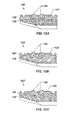
- When conventional inserts are used in non-metallic slips, they are arranged and oriented as shown in
Figure 1A , for example. Theslip 20 is disposed adjacent amandrel 10 of a downhole tool, such as a bridge plug, a packer, or the like. As shown inFigure 1B , theslip 20 moves away from themandrel 10 and engages against a surrounding tubular or casing wall when theslip 20 and acone 12 are moved toward one another. Either theslip 20 is pushed against the ramped surface of thecone 12, thecone 12 is pushed under theslip 20, or both. -
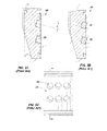
Figure 2A illustrates a side cross-section of aslip 20 havingholes 23 according to the prior art for inserts (not shown), andFigure 2B illustrates a side cross-section of theslip 20 withinserts 30 disposed in theholes 23.Figure 2C illustrates a front view of theslip 20 with theholes 23 for the inserts (not shown). Theslip 20 can have a semi-cylindrical shape. Theholes 23 in the surface of theslip 20 can be an array of blind pockets. Theinserts 30 are anchor studs that load into theholes 23 and can be held with a press fit or adhesive. - Examples of downhole tools with slips and inserts such as those above are disclosed in
U.S. Pat. Nos. 5,984,007 ;6,976,534 ; and8,047,279 . Other examples include Halliburton Obsidian® and Fas Drill® Fusion composite plugs and Boss Hog frac plugs. (OBSIDIAN and FAS DRILL are registered trademarks of Halliburton Energy Services, Inc.) - One particular type of downhole tool having slips is a composite fracture plug used in perforation and fracture operations. During the operations, the composite plugs need to be drilled up in as short of a period of time as possible and with no drill up issues. Conventional composite plugs use metallic wicker style slips, which are composed of cast iron. These metallic slips increase the metallic content of the plug and can cause issues during drill up in horizontal wells, especially when coil tubing is used during the milling operation.
- Due to the drawbacks of cast iron slips, composite slips having inserts, such as described above, are preferably used to reduce the issues associated with metallic slips. Unfortunately, a large amount of metallic debris can still collect at the heel of the well and cause drill up problems when composite slips having inserts are used on tools. When composite slips are used, for example, the inserts are typically composed of carbide, which is a dense and heavy material. In other developments, it is known to use a composite slip having an insert composed of ceramic and an insert composed of a metallic ceramic composite, such as described in
U.S. Pat. No. 6,976,534 . - In any event, when the downhole tool having slips with carbide inserts are milled out of the casing, the inserts tend to collect in the casing and are hard to float back to the surface. In fact, in horizontal wells, the carbide inserts may tend to collect at the heel of the horizontal section and cause potential problems for operations. Given that a well may have upwards of forty or fifty bridge plugs used during operations that are later milled out, a considerable number of carbide inserts may be left in the casing and difficult to remove from downhole. Additionally, non-metallic buttons used to bite into the casing may tend to fracture due to loads applied onto them during the setting process. This leads to a loss in structural integrity and inability to retain the position of the bridge plug in the well consistently.
- The subject matter of the present disclosure is directed to overcoming, or at least reducing the effects of, one or more of the problems set forth above.
- Various aspects of the present invention are defined in the independent claims appended herewith. Some preferred features are defined in the dependent claims appended herewith.
- According to a first aspect, there is provided a downhole apparatus for engaging in a downhole tubular, the apparatus comprising: at least one slip disposed on the apparatus and being movable relative to the apparatus; and at least one insert disposed on the at least one slip and adapted to engage the downhole tubular. The at least one insert may be at least composed of first and second materials, the first and second materials being different from one another and being geometrically separate from one another.
- The at least one slip may comprise a slip body composed of a non-metallic material.
- The non-metallic material may comprise a plastic, a molded phenolic, a laminated non-metallic composite, an epoxy resin polymer with a glass fiber reinforcement, an ultra-high-molecular-weight polyethylene (UHMW), a polytetrafluroethylene (PTFE), or a combination thereof.
- The at least one slip may comprise a plurality of segments disposed about the apparatus.
- The first material may comprise a ceramic material. The ceramic material may comprise alumina, zirconia, or cermet.
- The second material may comprise a metallic, a non-metallic, or a composite material. The second material may comprise a cast iron, a carbide, a metallic-ceramic composite material, a cermet, a powdered metal, or a combination thereof.
- At least one of the first and second materials may comprise a dissolvable material.
- The apparatus may comprise a mandrel having the at least one slip disposed thereon. The apparatus may comprise a cone disposed on the mandrel adjacent the at least one slip. The cone and the at least one slip may be movable relative to one another and moving the at least one slip toward the downhole tubular.
- The apparatus may comprise a sealing element disposed on the mandrel and being compressible to engage the downhole tubular.
- The first material of the at least one insert may comprise a core of the at least one insert having an outside surface. The second material of the at least one insert may comprise a sheath disposed about at least a portion of the outside of the core.
- The first material of the at least one insert may comprise a core of the at least one insert having an end. The second material of the at least one insert may comprise a layer disposed on the end of the core.
- The first material of the at least one insert may comprise first layers of the at least one insert. The second material of the at least one insert may comprise second layers interposed between the first layers of the at least one insert.
- The first and second layers may be arranged at an angle relative to an axis of the at least one insert. The angle may be orthogonal or parallel to the axis of the at least one insert.
- The first material of the at least one insert may comprise a core of the at least one insert. The second material of the at least one insert may comprise elements distributed inside the core.
- According to a second aspect, there is provided a downhole apparatus for engaging in a downhole tubular, the apparatus comprising: at least one slip disposed on the apparatus and being movable relative to the apparatus. The at least one slip may be at least composed of first and second materials, the first and second materials being different from one another and being geometrically separate from one another. The apparatus may comprise at least one insert disposed on the at least one slip and being adapted to engage the downhole tubular.
- The at least one insert may be at least composed of third and fourth materials, the third and fourth materials being different from one another and being geometrically separate from one another.
- The at least one slip may comprise a plurality of segments disposed about the apparatus.
- The first material may comprise a ceramic material. The ceramic material may comprise alumina, zirconia, or cermet.
- The second material may comprise a metallic, a non-metallic, or a composite material. The second material may comprise a cast iron, a carbide, a metallic-ceramic composite material, a cermet, a powdered metal, or a combination thereof.
- The first material may comprise a core of the at least one slip having an outside surface. The second material of the at least one slip may comprise a sheath disposed about at least a portion of the outside of the core.
- The first material may comprise first layers of the at least one slip. The second material of the at least one slip may comprise second layers interposed between the first layers of the at least one slip.
- The first and second layers may be arranged at an angle relative to an axis of the at least one slip.
- A downhole apparatus or tool, such as a composite bridge plug used during a fracture or perforation operations, installs in a downhole tubular, such as casing. The tool can have a mandrel with a sealing element disposed thereon. The sealing element can be compressible to engage the downhole tubular when the tool is activated by a wireline unit or the like.
- A slip is disposed on the tool and is movable relative to the tool to engage the downhole tubular. The slip can have one or more slip bodies, segments, or elements disposed about the mandrel. For example, the segments can be arranged around the tool and can be individual or integrated segments, although other arrangements for the slip can be used. The slip can be composed of a non-metallic material, such as a plastic, a molded phenolic, a composite, a laminated non-metallic composite, an epoxy resin polymer with a glass fiber reinforcement, an ultra-high-molecular-weight polyethylene (UHMW), a polytetrafluroethylene (PTFE), etc.
- One or more of the slips have one or more inserts composed of at least two materials, which may or may not be the same as one another. The materials are different from one another and are geometrically separate from one another. For example, one material may be a ceramic material, and the other material may be a metallic, a non-metallic, or a composite material. In another example, one material may be aluminum or other metal, and the other material may be tungsten carbide.
- To achieve the geometric separation from one another, the at least two materials can be arranged in different geometric configurations on the insert, including layers, interposed central cores, outer disposed sheaths, distributed elements, and the like. Although the inserts have been primarily described herein as including two materials, it is envisioned that the inserts can be more than two materials in the geometric configurations disclosed herein.
- The ceramic material for the inserts of the slip can be alumina, zirconia, or cermet. Use of the ceramic material can reduce the overall metallic content of the tool and can facilitate milling of the tool from the downhole tubular after use. The metallic material for the inserts can use a cast iron, a carbide, a cermet (i.e., composites composed of ceramic and metallic materials), a powdered metal, or a combination thereof. One or both of the materials of the insert can also be a dissolvable material intended to dissolve or degrade over a period of time in response to a trigger, conditions in the well, or the like.
- The various arrangements noted herein can be interchanged and combined with one another in accordance with the teachings of the present disclosure. Additionally, the slip can be an individual body or segment, a unitary ring, one of a plurality of independent segments of a slip assembly, or one of a plurality of integrated segments of a slip assembly. In one implementation, the slip can comprise at least two materials that are different from one another and that are geometrically separate from one another.
- Although suitable for a downhole tool, such as a fracture plug discussed above, the teaching of the present disclosure can apply to any of a number of downhole tools for engaging in a downhole tubular.
- The foregoing summary is not intended to summarize each potential embodiment or every aspect of the present disclosure. It should be understood that the features defined above in accordance with any aspect of the present invention or below in relation to any specific embodiment of the invention may be utilised, either alone or in combination with any other defined feature, in any other aspect or embodiment of the invention.
-
-
Fig. 1A illustrates inserts used in a non-metallic slip according to the prior art. -
Fig. 1B illustrates the slip ofFig. 1A during use. -
Fig. 2A illustrates a side cross-section of a slip having holes for inserts according to the prior art. -
Fig. 2B illustrates a side cross-section of the slip with inserts disposed in the holes. -
Fig. 2C illustrates a front view of the slip with the holes for the inserts. -
Fig. 3 illustrates a downhole tool in partial cross-section having slip assemblies according to the present disclosure. -
Fig. 4 illustrates a cross-sectional view of a slip having a first type of slip insert. -
Fig. 5 illustrates a slip assembly having partially interconnected segments. -
Figs. 6A-6C illustrate top, cross-sectional, and perspective views of one configuration of a slip insert. -
Figs. 7A-7C illustrate top, cross-sectional, and perspective views of another configuration of a slip insert. -
Figs. 8A through 10B illustrate perspective, cross-sectional views of internal configurations of slip inserts according to the present disclosure. -
Fig. 11 illustrates a perspective, cross-sectional view of another internal configuration of a slip insert according to the present disclosure. -
Figs. 12A-12C illustrate cross-sectional views of a slip segment according to the present disclosure. -
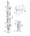
Figure 3 illustrates adownhole tool 100 in partial cross-section havingslip assemblies downhole tool 100 can be a bridge plug as shown, but it could also be a packer, a liner hanger, an anchoring device, or other downhole tool that uses a slip assembly to engage a downhole tubular, such as casing. - The
tool 100 has a mandrel 102 having theslip assemblies packing element 150. Outside theinclined cones 112, theslip assemblies slips 120 along with thecones 112 can be referred to as slip assemblies, or in other instances, just theslips 120 may be referred to as slip assemblies. In either case, either reference may be used interchangeably throughout the present disclosure. Thus, reference herein to a slip is not meant to refer only to one slip body, segment, or element, although it can. Instead, reference to slip can refer to more than just these connotations. As shown herein,slip assemblies slips 120, but other arrangements could be used. - As a bridge plug, the
tool 100 is preferably composed mostly of non-metallic components according to procedures and details as disclosed, for example, inU.S. Pat. No. 7,124,831 , which is incorporated herein by reference in its entirety. This makes thetool 100 easy to mill out after use. - When deployed downhole, the
tool 100 is activated by a wireline setting tool (not shown), which uses conventional techniques of pulling against the mandrel 102 while simultaneously pushing upper components against theslip assemblies slips 120 of theslip assemblies cones 112, thecones 112 move along the mandrel 102 toward one another, and thepacking element 150 compresses and extends outward to engage a surrounding casing wall. Thebackup elements 140 control the extrusion of thepacking element 150. In the process, theslips 120 on theassemblies tool 100 in place in the casing and keeps thepacking element 150 contained. - The force used to set the
tool 100 may be as high as 30,000 lbf and could be as high as 85,000 lbf. These values are only meant to be examples and could vary for the size of thetool 100. In any event, theset tool 100 isolates upper and lower portions of the casing so that fracture and other operations can be completed uphole of thetool 100, while pressure is kept from downhole locations. When used during fracture operations, for example, thetool 100 may isolate pressures of 10,000 psi or so. - As will be appreciated, any slipping or loosening of the
tool 100 can compromise operations. Therefore, theslips 120 need to sufficiently grip the inside of the casing.Inserts 130 on theslips 120 engage in the casing. - At the same time, however, the
tool 100 and most of its components are preferably composed of millable materials because thetool 100 is milled out of the casing once operations are done, as noted previously. As many as fiftysuch tools 100 can be used in one well and must be milled out at the end of operations. Therefore, havingreliable tools 100 composed of entirely of millable material is of particular interest to operators. To that end, theslip assemblies tools 100, such as bridge plugs, packers, and other downhole tools, and the challenges they offer. - As shown in
Figure 4 , one type ofslip 120 for the assemblies 110 has a slip body orsegment 122 with one or more individual inserts orbuttons 130 disposed therein. Thesegment 122 can be one of several used on a slip assembly. For example, thesegment 122 can be an independent slip component held around the tool's mandrel as inFigure 3 with other slip segments and supported by bands. - In general, the
segment 122 has anincline 124 for riding on a cone or other component of the downhole tool.Grooves 126 for bands may be provided in the outer surface depending on how thesegment 122 is held to the downhole tool. In general, thesegment 122 inFigure 4 can have any number ofinserts 130 arranged in one or more rows and/or one or more columns in the top surface. For instance, two rows ofinserts 130 may be used, each having the same number of columns. Alternatively, two rows can be used, but one row may have two columns while the other has one column. These and other configurations can be used as will be appreciated. - In one arrangement, the
inserts 130 can be the same size and can be disposed in equivalentsized holes 123 in theslip segment 122. In another arrangement, the depth ofholes 123 can vary from segment to segment or from slip assembly to slip assembly. Therefore, one ormore inserts 130 can be longer than the others. Additionally, the height of theinserts 130 can be the same on the givenslip segment 122 once installed, but the depth of theholes 123 can vary. This can reduce the stress around theinsert 130 in the base material. Other arrangements may have theinserts 130 at different heights and different depths relative to theslip segment 122. - In both cases, the
slip body 122 can comprise one of several independent segments of a slip assembly, such as onassemblies Figure 3 . As shown inFigure 3 , each body orsegment 122 can have the same arrangement and number ofinserts 130, although different arrangements can be used. Additionally, eachsegment 122 can be composed of the same or different materials from theother segments 122, and eachinsert 130 on a givensegment 122 may be composed of the same or different materials from the other inserts 130. In other arrangements such as shown inFigure 5 , theslip body 122 can be a unitary ring or can be a partially integrated ring, as disclosed herein. Also as shown, the unitary ring of theslip body 122 may includefeatures 121, such as splits, divisions, scores, slots or the like, to facilitate expansion of theslip body 122 when pushed against thecone 112. - In general, the
slip body 122 is composed of a first material, and the one ormore inserts 130 are composed of second materials exposed in the body's outer surface. The first material of theslip body 122 can generally be metal, composite, or the like. Preferably, theslip body 122 is composed of a millable material, such as a plastic, a non-metallic material, a molded phenolic, a laminated non-metallic composite, an epoxy resin polymer with a glass fiber reinforcement, an ultra-high-molecular-weight polyethylene (UHMW), a polytetrafluroethylene (PTFE), etc. - As disclosed in more detail below, the
inserts 130 of the present disclosure have internal configurations of at least two materials that are geometrically separate from one another, having multiple layers, components, elements, or the like. The materials used for theinserts 130 can in general include metallic or non-metallic materials. For example, theinserts 130 can be composed of a carbide, a metallic material, a cast iron, a composite, a ceramic, a cermet (i.e., composites composed of ceramic and metallic materials), a powdered metal, or the like. Additionally, theinserts 130 preferably have a sufficient hardness, which may be a hardness equivalent to at least about 50-60 Rc. The powdered metal used can include a sinter-hardened powder metal steel material, although other types of powder metals, such as steel, iron, or high carbon steel materials can be used. The ceramic material of theinsert 130 can be reinforced with metal or metal matrix composites (MMC). - Additionally, the materials used for the
inserts 130 can be a dissolvable material that dissolves over a period of time in response to a trigger, a condition in the well, or the like. The dissolvable material can be used for all of the materials of theinsert 130 or for one or more features of the insert's configurations (e.g., layers, components, elements, or the like), as disclosed below. Even if only a portion of theinsert 130 is dissolvable, then theinsert 130 will reduce to a smaller button size after use and there will be less material left in the well. - As an example of using a dissolvable material, the slip inserts 130 for the
upper slip assembly 110U ofFigure 3 can use a dissolvable material because theupper slip 110U may be used primarily to hold back thepacking element 150 during setting. Therefore, the upper slip inserts 130 can be made at least partially using a dissolvable material to reduce the amount of metallic content during mill-up after a fracture operation has been completed. Indeed, even theslips 120 of theupper assembly 110U can be made at least partially using a dissolvable material in the geometric configuration of theslips 120. - The shape of the
inserts 130 can be the same or different from one another. In general, theinserts 130 can be cylindrical as shown inFigure 4 or can have other shapes. For example, theinsert 130 can have different geometries, such as those disclosed inU.S. Appl. No. 14/039,032, filed 27-SEP-2013 , which is incorporated herein by reference in its entirety. - For instance,
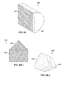
Figures 6A through 7C show examples of suitable geometries for theinsert 130.Figures 6A-6C show top, cross-sectional, and perspective views of a cylindrical shape for aninsert 130 of the present disclosure. The generallycylindrical insert 130 can have a diameter of about 0.3150-in., as shown on the top 132 ofFigure 5A . The overall height H1 can be about 0.375-in. These and other dimensions discussed herein are merely meant to provide example values. -
Figures 7A-7C show top, cross-sectional, and perspective views of another configuration for theinsert 130 for the present disclosure. Thisinsert 130 is also generally cylindrical with a diameter of 0.375-in., as shown inFigure 7A . Theinsert 130 has an overall height H2 of about 0.423-in. Thetop end 132 of theinsert 130, however, is cusped. Leading and tailing sides of the top end can be angled at 45-degrees. Other possible configurations for theinsert 130 are disclosed in incorporatedU.S. Appl. No. 14/039,032 . In fact, theinserts 130 can have other shapes rather than cylindrical buttons and can instead have the shape of an elongated strip, such as a wicker, or have other shapes as disclosed in incorporatedU.S. Appl. No. 14/039,032 . - To get consistent results and not degrade the mechanical integrity, the
inserts 130 of the present disclosure have internal configurations of the materials that are geometrically separate from one another, having multiple layers, components, elements, or the like. In particular, theinserts 130 depicted so far inFigures 3 through 7C have an inner core layer surrounded by an outer layer.Figures 8A through 11 illustrate perspective, cross-sectional views of internal configurations of slip inserts 130 according to the present disclosure. - For example, the
insert 130 may be composed primarily of a ceramic and can then have one or more metal, non-metal, or composite layers interposed therein and/or disposed thereabout. The layers can be used as a shield to protect theinsert 130 during the setting process. For example,Figure 8A shows theinsert 130 having a core 140 composed of a first material surrounded by anouter shield 142 composed of a second material. InFigure 8B , the same geometry is used, but the first and second materials are reversed. Although only two different materials are shown in these embodiment (as well as in any other embodiment disclosed herein), it will be appreciated with the benefit of the present disclosure that at least two materials can be used so that additional embodiments can include more than two materials in accordance with the present teachings. - In the arrangement of
Figure 8A , for example, thecore 140 can be composed of a ceramic material disposed in theouter shield 142 composed of a metallic, a non-metallic, or a composite material.Figure 8B is the reverse of this. In another option, thecore 140 can be composed of a powdered metal, and theshield 142 can be composed of a different metal or a tungsten carbide. Alternatively, thecore 140 can be tungsten carbide, and theshield 142 can be composed of a different material. These and other variations can be used. - As shown in
Figure 9A , theinsert 130 includes a core 140 composed of a first material having atop layer 144 of a second material disposed thereon. Thistop layer 144 can be a metal, a non-metal, or a composite material disposed on thecore 140, and thetop layer 144 can be used as a shield to protect thecore 140 during the setting process. As one example, thecore 140 can be composed of a ceramic, while thetop layer 144 is composed of a tungsten carbide. As another example, thecore 140 can be composed of a metal, while thetop layer 144 is composed of a tungsten carbide. A reverse arrangement of the materials for thelayer 144 andcore 140 can also be used. -
Figures 9B-1 and 9B-2 show a variation on this where theinsert 130 again has acore 140 and a top layer ortip 144. Thecore 140 can be composed of a metal, such as a "lighter metal" like aluminum, while thecap 144 can be composed of tungsten carbide or the like. InFigures 9C-1 and 9C-2 , yet another variation of theinsert 130 has acore 140 and anouter cap 146. Again, thecore 140 can be composed of a metal, and theouter cap 146 can be composed of tungsten carbide. With the benefit of the present disclosure, it will be appreciated that other variations of the materials can be used. - In yet another arrangement of
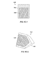
Figure 10A , theinsert 130 has multiple alternatinglayers 145a-b of a ceramic material and a metal, a non-metal, or a composite material disposed orthogonally to the axis A of theinsert 130. This arrangement can enhance the insert's hardness. Alternatively as shown inFigure 10B , theinsert 130 has multiple alternatinglayers 145a-b of a ceramic material and a metal, a non-metal, or a composite material disposed parallel to the axis A of theinsert 130. In yet another alternative, thelayers 145a-b can be arranged at other angles relative to the axis A of theinsert 130. -
Figure 11 illustrates a perspective, cross-sectional view of yet another internal configuration of aslip insert 130 according to the present disclosure. In this configuration, elements 148 (e.g., spheres, flakes, shards) of metal, non-metal, or composite material are distributed into acore 142 composed of another material (e.g., ceramic) during the manufacturing process to incorporate hardness and mitigate the propagation of fractures in the ceramic material during the setting and loading process. Theelements 148 can be substantially consistent with one another in size and shape and may be distributed evenly, although variations may be used. - Although not explicitly depicted, it will be appreciated with the benefit of the present disclosure that inserts 130 according to the present disclosure can use various combinations of the arrangements disclosed above. As such, use of layers, interposed central members, outer disposed members, distributed elements, and the like disclosed above can be combined together with one another to form additional configurations suitable for the
inserts 130 of the present disclosure. Moreover, any number of theinserts 130 used on a slip may have the same or different configuration. - Not only can the
inserts 130 benefit from the arrangements disclosed herein. In fact, theslip 120 in which theinserts 130 are used can having comparable arrangements of layers, interposed central members, outer disposed members, distributed elements, and the like disclosed above. As examples,Figures 12A-12B illustrate cross-sectional views of aslip 120 according to the presentdisclosure having inserts 130. - In these embodiments, the
body 122 of theslip 120 is composed of different materials. For example, thebody 122 inFigure 12A has a combination of first andsecond layers body 122. One of theselayers 126 can be composed of a ceramic material, while theother layers 128 can be composed of a second material (e.g., metal, non-metal, or composite). Other variations of material can be used. - As shown in
Figure 12A , theslip body 122 can be composed primarily of the ceramic material of thefirst layers 126, and the second material (e.g., metal, non-metal, or composite) disposed in thesecond layers 128 can be dispersed in theslip body 122. Thelayers slip body 122, although other arrangements can be used. - By contrast, the
slip body 122 inFigure 12B can be composed primarily of acore 125 of a first material, such as a ceramic material. Anouter cover 127 of a second material (e.g., metal, non-metal, or composite) can be disposed in a layer (at least partially) around thecore 125. Other variations of material can be used. - Further in line with the embodiments of the inserts, the
slip body 122 as shown inFigure 12C can have a comparable arrangement of first and second materials as the insert inFig. 11 . Namely, elements 129 (e.g., spheres, flakes, shards) of a first material are distributed into acore 125 composed of another material during the manufacturing process to incorporate hardness and mitigate the propagation of fractures in the core material during the setting and loading process. Theelements 129 can be substantially consistent with one another in size and shape and may be distributed evenly, although variations may be used. - The
slip 120 with these arrangements can carry higher loads than conventional composite slips, while the ceramic in the material will help break up theslip 120 during a mill-up, post fracing operation. Theslips 120 can likewise have other configurations and orientations, such as those disclosed in incorporatedU.S. Appl. No. 14/039,032 . - Manufacturing the
inserts 130 and/or slips 120 with the at least two materials as disclosed here depends in part on the types of materials being used. It will be appreciated that suitable bonding between the materials is required in some of the arrangements, such as layers, caps, tips, etc. Overall, bonding one of the materials to another of the materials disclosed herein can use composite manufacturing techniques. For example, bonding between surfaces of the materials in the disclosed arrangements can involve one or more of preparing the surfaces, applying adhesive, curing the adhesive, and applying pressure. Molding of the materials in the geometric arrangements can also be used depending on the materials involved, such as for embedded elements in a core material. Brazing, welding, and the like can also be used between the materials of the arrangements, such as between layers, core and surrounding shield, etc. Manufacturing theinserts 130 and/or slips 120 with the at least two materials can also involve press fitting the materials of the arrangements together. - Embodiments of the present disclosure can be characterized as follows. A downhole apparatus for engaging in a downhole tubular comprises at least one slip disposed on the apparatus and being movable relative to the apparatus toward the downhole tubular. At least one insert is disposed on the at least one slip and is adapted to engage the downhole tubular. The at least one insert is at least composed of first and second materials being different from one another and being geometrically separate from one another.
- The at least one slip can comprise a slip body composed of a non-metallic material, and the non-metallic material comprises a plastic, a molded phenolic, a laminated non-metallic composite, an epoxy resin polymer with a glass fiber reinforcement, an ultra-high-molecular-weight polyethylene (UHMW), a polytetrafluroethylene (PTFE), or a combination thereof. The at least one slip can comprise a plurality of segments disposed about the apparatus, such as about a mandrel of the apparatus.
- The first material can comprise a ceramic material, which can be alumina, zirconia, or cermet. The second material can comprise a metallic, a non-metallic, or a composite material, which can be a cast iron, a carbide, a metallic-ceramic composite material, a cermet, a powdered metal, or a combination thereof.
- The apparatus can have a mandrel having the at least one slip disposed thereon and can have a sealing element disposed on the mandrel and being compressible to engage the downhole tubular.
- In one embodiment, the first material of the at least one insert comprises a core, and the second material of the at least one insert comprises a sheath disposed about an outside of the core. In another embodiment, the first material of the at least one insert comprises a core, and the second material of the at least one insert comprises a layer disposed on an end of the core. In yet another embodiment, the first material of the at least one insert comprises first layers, and the second material of the at least one insert comprises second layers interposed between the first layers. The first and second layers can be arranged at an angle relative to an axis of the at least one insert. For example, the angle can be either orthogonal or parallel to the axis of the at least one insert. In still another embodiment, the first material of the at least one insert comprises a core, and the second material of the at least one insert comprises elements distributed in the core.
- Additional embodiments of the present disclosure can be characterized as follows. A downhole apparatus for engaging in a downhole tubular comprises at least one slip disposed on the apparatus and being movable relative to the apparatus toward the downhole tubular. The at least one slip is at least composed of first and second materials being different from one another and being geometrically separate from one another. At least one insert is disposed on the at least one slip and is adapted to engage the downhole tubular. This at least one insert can also be composed of third and fourth materials being different from one another.
- A downhole tool, such as a fracture plug used during a fracture operation, installs in a downhole tubular, such as casing. The tool has a mandrel with a sealing element disposed thereon between uphole and downhole ends. Slip assemblies on the mandrel can be moved to engage the downhole tubular. When the tool is used as a bridge plug, the uphole assembly supports the sealing element compressed, and the downhole assembly supports fluid pressure downhole of the tool. The slip assemblies have inserts composed of at least two materials that are different from one another and are geometrically separate from one another. In addition or as an alternative, the slip assemblies can be composed of at least two different materials that are geometrically separate from one another.
- The foregoing description of preferred and other embodiments is not intended to limit or restrict the scope or applicability of the inventive concepts conceived of by the Applicants. It will be appreciated with the benefit of the present disclosure that features described above in accordance with any embodiment or aspect of the disclosed subject matter can be utilized, either alone or in combination, with any other described feature, in any other embodiment or aspect of the disclosed subject matter.
- In exchange for disclosing the inventive concepts contained herein, the Applicants desire all patent rights afforded by the appended claims. Therefore, it is intended that the appended claims include all modifications and alterations to the full extent that they come within the scope of the following claims or the equivalents thereof.
Claims (15)
- A downhole apparatus for engaging in a downhole tubular, the apparatus comprising:at least one slip disposed on the apparatus and being movable relative to the apparatus; andat least one insert disposed on the at least one slip and adapted to engage the downhole tubular, the at least one insert being at least composed of first and second materials, the first and second materials being different from one another and being geometrically separate from one another.
- The apparatus of claim 1, wherein the at least one slip can comprise a slip body composed of a non-metallic material, wherein the non-metallic material optionally comprises a plastic, a molded phenolic, a laminated non-metallic composite, an epoxy resin polymer with a glass fiber reinforcement, an ultra-high-molecular-weight polyethylene (UHMW), a polytetrafluroethylene (PTFE), or a combination thereof.
- The apparatus of any preceding claim, wherein at least one of:the at least one slip can comprise a plurality of segments disposed about the apparatus; and/orthe first material comprises a ceramic material.
- The apparatus of claim 3, wherein at least one of:the ceramic material comprises alumina, zirconia, or cermet; and/orthe second material can comprise a metallic, a non-metallic, or a composite material, and the second material optionally comprises a cast iron, a carbide, a metallic-ceramic composite material, a cermet, a powdered metal, or a combination thereof.
- The apparatus of any preceding claim, wherein at least one of:the first and second materials comprises a dissolvable material; and/orthe apparatus comprises a mandrel having the at least one slip disposed thereon; and a cone disposed on the mandrel adjacent the at least one slip, the cone and the at least one slip being movable relative to one another and moving the at least one slip toward the downhole tubular.
- The apparatus of claim 5, comprising a sealing element disposed on the mandrel and being compressible to engage the downhole tubular.
- The apparatus of any preceding claim, wherein at least one of:the first material of the at least one insert comprises a core of the at least one insert having an outside surface; and wherein the second material of the at least one insert comprises a sheath disposed about at least a portion of the outside of the core; and/orthe first material of the at least one insert comprises a core of the at least one insert having an end; and wherein the second material of the at least one insert comprises a layer disposed on the end of the core; and/orthe first material of the at least one insert comprises first layers of the at least one insert; and wherein the second material of the at least one insert comprises second layers interposed between the first layers of the at least one insert; and/orthe first material of the at least one insert comprises a core of the at least one insert, and wherein the second material of the at least one insert comprises elements distributed inside the core.
- The apparatus of claim 7, wherein the first and second layers are arranged at an angle relative to an axis of the at least one insert.
- The apparatus of claim 8, wherein the angle is orthogonal or parallel to the axis of the at least one insert.
- A downhole apparatus for engaging in a downhole tubular, the apparatus comprising:at least one slip disposed on the apparatus and being movable relative to the apparatus, the at least one slip being at least composed of first and second materials, the first and second materials being different from one another and being geometrically separate from one another; andat least one insert disposed on the at least one slip and being adapted to engage the downhole tubular.
- The apparatus of claim 10, wherein at least one of:the at least one insert is at least composed of third and fourth materials, the third and fourth materials being different from one another and being geometrically separate from one another; and/orthe at least one slip can comprise a plurality of segments disposed about the apparatus; and/orthe first material comprises a ceramic material.
- The apparatus of claim 11, wherein at least one of:the ceramic material comprises alumina, zirconia, or cermet; and/orthe second material can comprise a metallic, a non-metallic, or a composite material.
- The apparatus of claim 12, wherein the second material comprises a cast iron, a carbide, a metallic-ceramic composite material, a cermet, a powdered metal, or a combination thereof.
- The apparatus of any of claims 10 to 13, wherein at least one of:the first material comprises a core of the at least one slip having an outside surface; and wherein the second material of the at least one slip comprises a sheath disposed about at least a portion of the outside of the core; and/orthe first material comprises first layers of the at least one slip; and wherein the second material of the at least one slip comprises second layers interposed between the first layers of the at least one slip.
- The apparatus of claim 14, wherein the first and second layers are arranged at an angle relative to an axis of the at least one slip.
Applications Claiming Priority (1)
| Application Number | Priority Date | Filing Date | Title |
|---|---|---|---|
| US201462013835P | 2014-06-18 | 2014-06-18 |
Publications (3)
| Publication Number | Publication Date |
|---|---|
| EP2957712A2 true EP2957712A2 (en) | 2015-12-23 |
| EP2957712A3 EP2957712A3 (en) | 2016-03-02 |
| EP2957712B1 EP2957712B1 (en) | 2017-10-04 |
Family
ID=53434277
Family Applications (1)
| Application Number | Title | Priority Date | Filing Date |
|---|---|---|---|
| EP15172687.4A Not-in-force EP2957712B1 (en) | 2014-06-18 | 2015-06-18 | Inserts having geometrically separate materials for slips on downhole tool |
Country Status (5)
| Country | Link |
|---|---|
| US (1) | US10415335B2 (en) |
| EP (1) | EP2957712B1 (en) |
| AU (1) | AU2015203333B2 (en) |
| CA (2) | CA2972906C (en) |
| NO (1) | NO3120944T3 (en) |
Families Citing this family (21)
| Publication number | Priority date | Publication date | Assignee | Title |
|---|---|---|---|---|
| US10036221B2 (en) | 2011-08-22 | 2018-07-31 | Downhole Technology, Llc | Downhole tool and method of use |
| US10316617B2 (en) | 2011-08-22 | 2019-06-11 | Downhole Technology, Llc | Downhole tool and system, and method of use |
| US10570694B2 (en) | 2011-08-22 | 2020-02-25 | The Wellboss Company, Llc | Downhole tool and method of use |
| US9103177B2 (en) | 2011-08-22 | 2015-08-11 | National Boss Hog Energy Services, Llc | Downhole tool and method of use |
| US20180128073A1 (en) * | 2016-11-08 | 2018-05-10 | Magnum Oil Tools International, Ltd. | Powder metal gripping elements for settable downhole tools having slips |
| GB201418128D0 (en) * | 2014-10-14 | 2014-11-26 | Weatherford Uk Ltd | Downhole anchor |
| AU2017291750B2 (en) * | 2016-07-05 | 2019-07-18 | The Wellboss Company, Llc | Downhole tool and method of use |
| MX2018006794A (en) | 2016-11-17 | 2018-11-09 | Downhole Tech Llc | Downhole tool and method of use. |
| CA3071108A1 (en) * | 2017-07-26 | 2019-01-31 | Peak Completion Technologies, Inc. | Improved frac plug |
| GB2581059B (en) | 2018-04-12 | 2022-08-31 | The Wellboss Company Llc | Downhole tool with bottom composite slip |
| US10801298B2 (en) | 2018-04-23 | 2020-10-13 | The Wellboss Company, Llc | Downhole tool with tethered ball |
| US10961796B2 (en) | 2018-09-12 | 2021-03-30 | The Wellboss Company, Llc | Setting tool assembly |
| US11193347B2 (en) * | 2018-11-07 | 2021-12-07 | Petroquip Energy Services, Llp | Slip insert for tool retention |
| CA3154895A1 (en) | 2019-10-16 | 2021-04-22 | Gabriel Slup | Downhole tool and method of use |
| US11634965B2 (en) | 2019-10-16 | 2023-04-25 | The Wellboss Company, Llc | Downhole tool and method of use |
| US11230903B2 (en) | 2020-02-05 | 2022-01-25 | Weatherford Technology Holdings, Llc | Downhole tool having low density slip inserts |
| US11293244B2 (en) * | 2020-02-28 | 2022-04-05 | Weatherford Technology Holdings, Llc | Slip assembly for a downhole tool |
| US20210340838A1 (en) * | 2020-05-01 | 2021-11-04 | Baker Hughes Oilfield Operations Llc | Slip with multi piece button and system |
| US11377920B2 (en) | 2020-09-03 | 2022-07-05 | Halliburton Energy Services, Inc. | Anchoring downhole tool housing and body to inner diameter of tubing string |
| CN112943122A (en) * | 2021-01-20 | 2021-06-11 | 中国石油天然气股份有限公司 | Dissolvable support slip, dissolvable metal wellbore switching system and methods of use |
| WO2022181685A1 (en) | 2021-02-26 | 2022-09-01 | 株式会社クレハ | Downhole tool securing device and frac plug |
Citations (4)
| Publication number | Priority date | Publication date | Assignee | Title |
|---|---|---|---|---|
| US5984007A (en) | 1998-01-09 | 1999-11-16 | Halliburton Energy Services, Inc. | Chip resistant buttons for downhole tools having slip elements |
| US6976534B2 (en) | 2003-09-29 | 2005-12-20 | Halliburton Energy Services, Inc. | Slip element for use with a downhole tool and a method of manufacturing same |
| US7124831B2 (en) | 2001-06-27 | 2006-10-24 | Weatherford/Lamb, Inc. | Resin impregnated continuous fiber plug with non-metallic element system |
| US8047279B2 (en) | 2009-02-18 | 2011-11-01 | Halliburton Energy Services Inc. | Slip segments for downhole tool |
Family Cites Families (10)
| Publication number | Priority date | Publication date | Assignee | Title |
|---|---|---|---|---|
| US2888247A (en) * | 1955-12-13 | 1959-05-26 | Sandvikens Jernverks Ab | Rock drill cutting insert of sintered hard metal |
| US4823919A (en) | 1986-09-15 | 1989-04-25 | Premiere Casing Services, Inc. | Slip construction for supporting tubular members |
| US7424909B2 (en) | 2004-02-27 | 2008-09-16 | Smith International, Inc. | Drillable bridge plug |
| GB0423597D0 (en) * | 2004-10-23 | 2004-11-24 | Reedhycalog Uk Ltd | Dual-edge working surfaces for polycrystalline diamond cutting elements |
| US7407012B2 (en) * | 2005-07-26 | 2008-08-05 | Smith International, Inc. | Thermally stable diamond cutting elements in roller cone drill bits |
| US8695714B2 (en) | 2011-05-19 | 2014-04-15 | Baker Hughes Incorporated | Easy drill slip with degradable materials |
| US8794309B2 (en) | 2011-07-18 | 2014-08-05 | Baker Hughes Incorporated | Frangible slip for downhole tools |
| US9027655B2 (en) | 2011-08-22 | 2015-05-12 | Baker Hughes Incorporated | Degradable slip element |
| US9725981B2 (en) | 2012-10-01 | 2017-08-08 | Weatherford Technology Holdings, Llc | Non-metallic slips having inserts oriented normal to cone face |
| US9416617B2 (en) * | 2013-02-12 | 2016-08-16 | Weatherford Technology Holdings, Llc | Downhole tool having slip inserts composed of different materials |
-
2014
- 2014-03-11 NO NO16182740A patent/NO3120944T3/no unknown
-
2015
- 2015-06-15 US US14/739,962 patent/US10415335B2/en not_active Expired - Fee Related
- 2015-06-17 CA CA2972906A patent/CA2972906C/en not_active Expired - Fee Related
- 2015-06-17 CA CA2894749A patent/CA2894749C/en not_active Expired - Fee Related
- 2015-06-17 AU AU2015203333A patent/AU2015203333B2/en not_active Ceased
- 2015-06-18 EP EP15172687.4A patent/EP2957712B1/en not_active Not-in-force
Patent Citations (4)
| Publication number | Priority date | Publication date | Assignee | Title |
|---|---|---|---|---|
| US5984007A (en) | 1998-01-09 | 1999-11-16 | Halliburton Energy Services, Inc. | Chip resistant buttons for downhole tools having slip elements |
| US7124831B2 (en) | 2001-06-27 | 2006-10-24 | Weatherford/Lamb, Inc. | Resin impregnated continuous fiber plug with non-metallic element system |
| US6976534B2 (en) | 2003-09-29 | 2005-12-20 | Halliburton Energy Services, Inc. | Slip element for use with a downhole tool and a method of manufacturing same |
| US8047279B2 (en) | 2009-02-18 | 2011-11-01 | Halliburton Energy Services Inc. | Slip segments for downhole tool |
Also Published As
| Publication number | Publication date |
|---|---|
| AU2015203333A1 (en) | 2016-01-21 |
| US20150368994A1 (en) | 2015-12-24 |
| CA2972906C (en) | 2020-02-11 |
| AU2015203333B2 (en) | 2016-06-09 |
| CA2972906A1 (en) | 2015-12-18 |
| CA2894749A1 (en) | 2015-12-18 |
| US10415335B2 (en) | 2019-09-17 |
| NO3120944T3 (en) | 2018-10-20 |
| EP2957712A3 (en) | 2016-03-02 |
| CA2894749C (en) | 2017-08-22 |
| EP2957712B1 (en) | 2017-10-04 |
Similar Documents
| Publication | Publication Date | Title |
|---|---|---|
| EP2957712B1 (en) | Inserts having geometrically separate materials for slips on downhole tool | |
| CA2988655C (en) | Downhole tool having slip inserts composed of different materials | |
| US9677356B2 (en) | Insert units for non-metallic slips oriented normal to cone face | |
| AU2013237721B2 (en) | Non-metallic slips having inserts oriented normal to cone face | |
| US10246967B2 (en) | Downhole system for use in a wellbore and method for the same | |
| US9157288B2 (en) | Downhole tool system and method related thereto | |
| US20140262214A1 (en) | Bonded Segmented Slips | |
| US20160281458A1 (en) | Retrievable Downhole Tool | |
| US9470060B2 (en) | Standoff device for downhole tools using slip elements | |
| CN109563733B (en) | High expansion metal support ring for packer and bridge plug | |
| US10400535B1 (en) | Retrievable downhole tool | |
| EP2835492B1 (en) | Insert units for non-metallic slips | |
| US11230903B2 (en) | Downhole tool having low density slip inserts | |
| AU2014208263B2 (en) | Insert units for non-metallic slips oriented normal to cone face | |
| BR102015014623A2 (en) | INSERTS HAVING GEOMETRICALLY SEPARATED MATERIALS FOR HARNESS IN THE WELL TOOL TOOL |
Legal Events
| Date | Code | Title | Description |
|---|---|---|---|
| PUAI | Public reference made under article 153(3) epc to a published international application that has entered the european phase |
Free format text: ORIGINAL CODE: 0009012 |
|
| 17P | Request for examination filed |
Effective date: 20150618 |
|
| AK | Designated contracting states |
Kind code of ref document: A2 Designated state(s): AL AT BE BG CH CY CZ DE DK EE ES FI FR GB GR HR HU IE IS IT LI LT LU LV MC MK MT NL NO PL PT RO RS SE SI SK SM TR |
|
| AX | Request for extension of the european patent |
Extension state: BA ME |
|
| PUAL | Search report despatched |
Free format text: ORIGINAL CODE: 0009013 |
|
| AK | Designated contracting states |
Kind code of ref document: A3 Designated state(s): AL AT BE BG CH CY CZ DE DK EE ES FI FR GB GR HR HU IE IS IT LI LT LU LV MC MK MT NL NO PL PT RO RS SE SI SK SM TR |
|
| AX | Request for extension of the european patent |
Extension state: BA ME |
|
| RIC1 | Information provided on ipc code assigned before grant |
Ipc: E21B 23/01 20060101AFI20160122BHEP Ipc: E21B 33/129 20060101ALI20160122BHEP |
|
| GRAP | Despatch of communication of intention to grant a patent |
Free format text: ORIGINAL CODE: EPIDOSNIGR1 |
|
| INTG | Intention to grant announced |
Effective date: 20170421 |
|
| GRAA | (expected) grant |
Free format text: ORIGINAL CODE: 0009210 |
|
| GRAS | Grant fee paid |
Free format text: ORIGINAL CODE: EPIDOSNIGR3 |
|
| AK | Designated contracting states |
Kind code of ref document: B1 Designated state(s): AL AT BE BG CH CY CZ DE DK EE ES FI FR GB GR HR HU IE IS IT LI LT LU LV MC MK MT NL NO PL PT RO RS SE SI SK SM TR |
|
| REG | Reference to a national code |
Ref country code: GB Ref legal event code: FG4D |
|
| REG | Reference to a national code |
Ref country code: CH Ref legal event code: EP |
|
| REG | Reference to a national code |
Ref country code: AT Ref legal event code: REF Ref document number: 934236 Country of ref document: AT Kind code of ref document: T Effective date: 20171015 |
|
| REG | Reference to a national code |
Ref country code: IE Ref legal event code: FG4D |
|
| REG | Reference to a national code |
Ref country code: DE Ref legal event code: R096 Ref document number: 602015005110 Country of ref document: DE |
|
| REG | Reference to a national code |
Ref country code: NO Ref legal event code: T2 Effective date: 20171004 |
|
| REG | Reference to a national code |
Ref country code: NL Ref legal event code: MP Effective date: 20171004 |
|
| REG | Reference to a national code |
Ref country code: LT Ref legal event code: MG4D |
|
| REG | Reference to a national code |
Ref country code: AT Ref legal event code: MK05 Ref document number: 934236 Country of ref document: AT Kind code of ref document: T Effective date: 20171004 |
|
| PG25 | Lapsed in a contracting state [announced via postgrant information from national office to epo] |
Ref country code: NL Free format text: LAPSE BECAUSE OF FAILURE TO SUBMIT A TRANSLATION OF THE DESCRIPTION OR TO PAY THE FEE WITHIN THE PRESCRIBED TIME-LIMIT Effective date: 20171004 |
|
| PG25 | Lapsed in a contracting state [announced via postgrant information from national office to epo] |
Ref country code: SE Free format text: LAPSE BECAUSE OF FAILURE TO SUBMIT A TRANSLATION OF THE DESCRIPTION OR TO PAY THE FEE WITHIN THE PRESCRIBED TIME-LIMIT Effective date: 20171004 Ref country code: ES Free format text: LAPSE BECAUSE OF FAILURE TO SUBMIT A TRANSLATION OF THE DESCRIPTION OR TO PAY THE FEE WITHIN THE PRESCRIBED TIME-LIMIT Effective date: 20171004 Ref country code: LT Free format text: LAPSE BECAUSE OF FAILURE TO SUBMIT A TRANSLATION OF THE DESCRIPTION OR TO PAY THE FEE WITHIN THE PRESCRIBED TIME-LIMIT Effective date: 20171004 Ref country code: FI Free format text: LAPSE BECAUSE OF FAILURE TO SUBMIT A TRANSLATION OF THE DESCRIPTION OR TO PAY THE FEE WITHIN THE PRESCRIBED TIME-LIMIT Effective date: 20171004 |
|
| PG25 | Lapsed in a contracting state [announced via postgrant information from national office to epo] |
Ref country code: IS Free format text: LAPSE BECAUSE OF FAILURE TO SUBMIT A TRANSLATION OF THE DESCRIPTION OR TO PAY THE FEE WITHIN THE PRESCRIBED TIME-LIMIT Effective date: 20180204 Ref country code: RS Free format text: LAPSE BECAUSE OF FAILURE TO SUBMIT A TRANSLATION OF THE DESCRIPTION OR TO PAY THE FEE WITHIN THE PRESCRIBED TIME-LIMIT Effective date: 20171004 Ref country code: HR Free format text: LAPSE BECAUSE OF FAILURE TO SUBMIT A TRANSLATION OF THE DESCRIPTION OR TO PAY THE FEE WITHIN THE PRESCRIBED TIME-LIMIT Effective date: 20171004 Ref country code: BG Free format text: LAPSE BECAUSE OF FAILURE TO SUBMIT A TRANSLATION OF THE DESCRIPTION OR TO PAY THE FEE WITHIN THE PRESCRIBED TIME-LIMIT Effective date: 20180104 Ref country code: LV Free format text: LAPSE BECAUSE OF FAILURE TO SUBMIT A TRANSLATION OF THE DESCRIPTION OR TO PAY THE FEE WITHIN THE PRESCRIBED TIME-LIMIT Effective date: 20171004 Ref country code: AT Free format text: LAPSE BECAUSE OF FAILURE TO SUBMIT A TRANSLATION OF THE DESCRIPTION OR TO PAY THE FEE WITHIN THE PRESCRIBED TIME-LIMIT Effective date: 20171004 Ref country code: GR Free format text: LAPSE BECAUSE OF FAILURE TO SUBMIT A TRANSLATION OF THE DESCRIPTION OR TO PAY THE FEE WITHIN THE PRESCRIBED TIME-LIMIT Effective date: 20180105 |
|
| REG | Reference to a national code |
Ref country code: DE Ref legal event code: R097 Ref document number: 602015005110 Country of ref document: DE |
|
| PG25 | Lapsed in a contracting state [announced via postgrant information from national office to epo] |
Ref country code: CZ Free format text: LAPSE BECAUSE OF FAILURE TO SUBMIT A TRANSLATION OF THE DESCRIPTION OR TO PAY THE FEE WITHIN THE PRESCRIBED TIME-LIMIT Effective date: 20171004 Ref country code: EE Free format text: LAPSE BECAUSE OF FAILURE TO SUBMIT A TRANSLATION OF THE DESCRIPTION OR TO PAY THE FEE WITHIN THE PRESCRIBED TIME-LIMIT Effective date: 20171004 Ref country code: SK Free format text: LAPSE BECAUSE OF FAILURE TO SUBMIT A TRANSLATION OF THE DESCRIPTION OR TO PAY THE FEE WITHIN THE PRESCRIBED TIME-LIMIT Effective date: 20171004 Ref country code: DK Free format text: LAPSE BECAUSE OF FAILURE TO SUBMIT A TRANSLATION OF THE DESCRIPTION OR TO PAY THE FEE WITHIN THE PRESCRIBED TIME-LIMIT Effective date: 20171004 |
|
| PGFP | Annual fee paid to national office [announced via postgrant information from national office to epo] |
Ref country code: NO Payment date: 20180611 Year of fee payment: 4 |
|
| PLBE | No opposition filed within time limit |
Free format text: ORIGINAL CODE: 0009261 |
|
| STAA | Information on the status of an ep patent application or granted ep patent |
Free format text: STATUS: NO OPPOSITION FILED WITHIN TIME LIMIT |
|
| PG25 | Lapsed in a contracting state [announced via postgrant information from national office to epo] |
Ref country code: RO Free format text: LAPSE BECAUSE OF FAILURE TO SUBMIT A TRANSLATION OF THE DESCRIPTION OR TO PAY THE FEE WITHIN THE PRESCRIBED TIME-LIMIT Effective date: 20171004 Ref country code: PL Free format text: LAPSE BECAUSE OF FAILURE TO SUBMIT A TRANSLATION OF THE DESCRIPTION OR TO PAY THE FEE WITHIN THE PRESCRIBED TIME-LIMIT Effective date: 20171004 Ref country code: SM Free format text: LAPSE BECAUSE OF FAILURE TO SUBMIT A TRANSLATION OF THE DESCRIPTION OR TO PAY THE FEE WITHIN THE PRESCRIBED TIME-LIMIT Effective date: 20171004 Ref country code: IT Free format text: LAPSE BECAUSE OF FAILURE TO SUBMIT A TRANSLATION OF THE DESCRIPTION OR TO PAY THE FEE WITHIN THE PRESCRIBED TIME-LIMIT Effective date: 20171004 |
|
| 26N | No opposition filed |
Effective date: 20180705 |
|
| PG25 | Lapsed in a contracting state [announced via postgrant information from national office to epo] |
Ref country code: SI Free format text: LAPSE BECAUSE OF FAILURE TO SUBMIT A TRANSLATION OF THE DESCRIPTION OR TO PAY THE FEE WITHIN THE PRESCRIBED TIME-LIMIT Effective date: 20171004 |
|
| REG | Reference to a national code |
Ref country code: DE Ref legal event code: R119 Ref document number: 602015005110 Country of ref document: DE |
|
| REG | Reference to a national code |
Ref country code: CH Ref legal event code: PL |
|
| REG | Reference to a national code |
Ref country code: BE Ref legal event code: MM Effective date: 20180630 |
|
| REG | Reference to a national code |
Ref country code: IE Ref legal event code: MM4A |
|
| PG25 | Lapsed in a contracting state [announced via postgrant information from national office to epo] |
Ref country code: LU Free format text: LAPSE BECAUSE OF NON-PAYMENT OF DUE FEES Effective date: 20180618 Ref country code: MC Free format text: LAPSE BECAUSE OF FAILURE TO SUBMIT A TRANSLATION OF THE DESCRIPTION OR TO PAY THE FEE WITHIN THE PRESCRIBED TIME-LIMIT Effective date: 20171004 |
|
| PG25 | Lapsed in a contracting state [announced via postgrant information from national office to epo] |
Ref country code: LI Free format text: LAPSE BECAUSE OF NON-PAYMENT OF DUE FEES Effective date: 20180630 Ref country code: FR Free format text: LAPSE BECAUSE OF NON-PAYMENT OF DUE FEES Effective date: 20180630 Ref country code: IE Free format text: LAPSE BECAUSE OF NON-PAYMENT OF DUE FEES Effective date: 20180618 Ref country code: CH Free format text: LAPSE BECAUSE OF NON-PAYMENT OF DUE FEES Effective date: 20180630 Ref country code: DE Free format text: LAPSE BECAUSE OF NON-PAYMENT OF DUE FEES Effective date: 20190101 |
|
| PG25 | Lapsed in a contracting state [announced via postgrant information from national office to epo] |
Ref country code: BE Free format text: LAPSE BECAUSE OF NON-PAYMENT OF DUE FEES Effective date: 20180630 |
|
| REG | Reference to a national code |
Ref country code: NO Ref legal event code: MMEP |
|
| PG25 | Lapsed in a contracting state [announced via postgrant information from national office to epo] |
Ref country code: MT Free format text: LAPSE BECAUSE OF NON-PAYMENT OF DUE FEES Effective date: 20180618 |
|
| GBPC | Gb: european patent ceased through non-payment of renewal fee |
Effective date: 20190618 |
|
| PG25 | Lapsed in a contracting state [announced via postgrant information from national office to epo] |
Ref country code: TR Free format text: LAPSE BECAUSE OF FAILURE TO SUBMIT A TRANSLATION OF THE DESCRIPTION OR TO PAY THE FEE WITHIN THE PRESCRIBED TIME-LIMIT Effective date: 20171004 |
|
| PG25 | Lapsed in a contracting state [announced via postgrant information from national office to epo] |
Ref country code: GB Free format text: LAPSE BECAUSE OF NON-PAYMENT OF DUE FEES Effective date: 20190618 Ref country code: NO Free format text: LAPSE BECAUSE OF NON-PAYMENT OF DUE FEES Effective date: 20190630 |
|
| PG25 | Lapsed in a contracting state [announced via postgrant information from national office to epo] |
Ref country code: PT Free format text: LAPSE BECAUSE OF FAILURE TO SUBMIT A TRANSLATION OF THE DESCRIPTION OR TO PAY THE FEE WITHIN THE PRESCRIBED TIME-LIMIT Effective date: 20171004 |
|
| PG25 | Lapsed in a contracting state [announced via postgrant information from national office to epo] |
Ref country code: CY Free format text: LAPSE BECAUSE OF FAILURE TO SUBMIT A TRANSLATION OF THE DESCRIPTION OR TO PAY THE FEE WITHIN THE PRESCRIBED TIME-LIMIT Effective date: 20171004 Ref country code: HU Free format text: LAPSE BECAUSE OF FAILURE TO SUBMIT A TRANSLATION OF THE DESCRIPTION OR TO PAY THE FEE WITHIN THE PRESCRIBED TIME-LIMIT; INVALID AB INITIO Effective date: 20150618 Ref country code: MK Free format text: LAPSE BECAUSE OF NON-PAYMENT OF DUE FEES Effective date: 20171004 |
|
| PG25 | Lapsed in a contracting state [announced via postgrant information from national office to epo] |
Ref country code: AL Free format text: LAPSE BECAUSE OF FAILURE TO SUBMIT A TRANSLATION OF THE DESCRIPTION OR TO PAY THE FEE WITHIN THE PRESCRIBED TIME-LIMIT Effective date: 20171004 |