EP2959856A1 - Assistive manual zeroing visualization - Google Patents
Assistive manual zeroing visualization Download PDFInfo
- Publication number
- EP2959856A1 EP2959856A1 EP15173886.1A EP15173886A EP2959856A1 EP 2959856 A1 EP2959856 A1 EP 2959856A1 EP 15173886 A EP15173886 A EP 15173886A EP 2959856 A1 EP2959856 A1 EP 2959856A1
- Authority
- EP
- European Patent Office
- Prior art keywords
- probe
- catheter
- blood pool
- image
- contact force
- Prior art date
- Legal status (The legal status is an assumption and is not a legal conclusion. Google has not performed a legal analysis and makes no representation as to the accuracy of the status listed.)
- Granted
Links
- 238000012800 visualization Methods 0.000 title description 3
- 239000008280 blood Substances 0.000 claims abstract description 57
- 210000004369 blood Anatomy 0.000 claims abstract description 57
- 239000000523 sample Substances 0.000 claims abstract description 46
- 210000002216 heart Anatomy 0.000 claims description 15
- 238000005259 measurement Methods 0.000 claims description 10
- 238000003780 insertion Methods 0.000 claims description 2
- 230000037431 insertion Effects 0.000 claims description 2
- 210000005242 cardiac chamber Anatomy 0.000 abstract description 14
- 238000000034 method Methods 0.000 description 58
- 210000001519 tissue Anatomy 0.000 description 27
- 238000002679 ablation Methods 0.000 description 22
- 230000007717 exclusion Effects 0.000 description 9
- 206010003119 arrhythmia Diseases 0.000 description 5
- 230000008859 change Effects 0.000 description 5
- 210000005003 heart tissue Anatomy 0.000 description 5
- 238000012545 processing Methods 0.000 description 5
- 230000000747 cardiac effect Effects 0.000 description 4
- 230000008569 process Effects 0.000 description 4
- 230000006793 arrhythmia Effects 0.000 description 3
- 238000010586 diagram Methods 0.000 description 3
- 230000003902 lesion Effects 0.000 description 3
- 230000037361 pathway Effects 0.000 description 3
- 230000002159 abnormal effect Effects 0.000 description 2
- 230000004913 activation Effects 0.000 description 2
- 229910003460 diamond Inorganic materials 0.000 description 2
- 239000010432 diamond Substances 0.000 description 2
- 238000011156 evaluation Methods 0.000 description 2
- 238000013507 mapping Methods 0.000 description 2
- 230000002792 vascular Effects 0.000 description 2
- 206010001497 Agitation Diseases 0.000 description 1
- 206010003658 Atrial Fibrillation Diseases 0.000 description 1
- 208000005228 Pericardial Effusion Diseases 0.000 description 1
- 206010034476 Pericardial haemorrhage Diseases 0.000 description 1
- 238000013459 approach Methods 0.000 description 1
- 230000000712 assembly Effects 0.000 description 1
- 238000000429 assembly Methods 0.000 description 1
- 230000015572 biosynthetic process Effects 0.000 description 1
- 239000000872 buffer Substances 0.000 description 1
- 239000013065 commercial product Substances 0.000 description 1
- 238000004590 computer program Methods 0.000 description 1
- 230000008602 contraction Effects 0.000 description 1
- 238000001816 cooling Methods 0.000 description 1
- 238000001514 detection method Methods 0.000 description 1
- 230000000694 effects Effects 0.000 description 1
- 210000001174 endocardium Anatomy 0.000 description 1
- 238000010438 heat treatment Methods 0.000 description 1
- 201000002303 hemopericardium Diseases 0.000 description 1
- 238000003384 imaging method Methods 0.000 description 1
- 239000007788 liquid Substances 0.000 description 1
- 230000004807 localization Effects 0.000 description 1
- 230000007246 mechanism Effects 0.000 description 1
- 238000012986 modification Methods 0.000 description 1
- 230000004048 modification Effects 0.000 description 1
- 230000002107 myocardial effect Effects 0.000 description 1
- 210000004165 myocardium Anatomy 0.000 description 1
- 210000000056 organ Anatomy 0.000 description 1
- 230000033764 rhythmic process Effects 0.000 description 1
- 210000005245 right atrium Anatomy 0.000 description 1
- 238000002604 ultrasonography Methods 0.000 description 1
- 238000012795 verification Methods 0.000 description 1
Images


Classifications
-
- A—HUMAN NECESSITIES
- A61—MEDICAL OR VETERINARY SCIENCE; HYGIENE
- A61B—DIAGNOSIS; SURGERY; IDENTIFICATION
- A61B17/00—Surgical instruments, devices or methods, e.g. tourniquets
- A61B17/00234—Surgical instruments, devices or methods, e.g. tourniquets for minimally invasive surgery
-
- A—HUMAN NECESSITIES
- A61—MEDICAL OR VETERINARY SCIENCE; HYGIENE
- A61B—DIAGNOSIS; SURGERY; IDENTIFICATION
- A61B18/00—Surgical instruments, devices or methods for transferring non-mechanical forms of energy to or from the body
- A61B18/04—Surgical instruments, devices or methods for transferring non-mechanical forms of energy to or from the body by heating
- A61B18/12—Surgical instruments, devices or methods for transferring non-mechanical forms of energy to or from the body by heating by passing a current through the tissue to be heated, e.g. high-frequency current
- A61B18/14—Probes or electrodes therefor
- A61B18/1492—Probes or electrodes therefor having a flexible, catheter-like structure, e.g. for heart ablation
-
- A—HUMAN NECESSITIES
- A61—MEDICAL OR VETERINARY SCIENCE; HYGIENE
- A61B—DIAGNOSIS; SURGERY; IDENTIFICATION
- A61B34/00—Computer-aided surgery; Manipulators or robots specially adapted for use in surgery
- A61B34/20—Surgical navigation systems; Devices for tracking or guiding surgical instruments, e.g. for frameless stereotaxis
-
- A—HUMAN NECESSITIES
- A61—MEDICAL OR VETERINARY SCIENCE; HYGIENE
- A61B—DIAGNOSIS; SURGERY; IDENTIFICATION
- A61B90/00—Instruments, implements or accessories specially adapted for surgery or diagnosis and not covered by any of the groups A61B1/00 - A61B50/00, e.g. for luxation treatment or for protecting wound edges
- A61B90/06—Measuring instruments not otherwise provided for
-
- A—HUMAN NECESSITIES
- A61—MEDICAL OR VETERINARY SCIENCE; HYGIENE
- A61B—DIAGNOSIS; SURGERY; IDENTIFICATION
- A61B17/00—Surgical instruments, devices or methods, e.g. tourniquets
- A61B17/00234—Surgical instruments, devices or methods, e.g. tourniquets for minimally invasive surgery
- A61B2017/00238—Type of minimally invasive operation
- A61B2017/00243—Type of minimally invasive operation cardiac
-
- A—HUMAN NECESSITIES
- A61—MEDICAL OR VETERINARY SCIENCE; HYGIENE
- A61B—DIAGNOSIS; SURGERY; IDENTIFICATION
- A61B17/00—Surgical instruments, devices or methods, e.g. tourniquets
- A61B2017/00681—Aspects not otherwise provided for
- A61B2017/00725—Calibration or performance testing
-
- A—HUMAN NECESSITIES
- A61—MEDICAL OR VETERINARY SCIENCE; HYGIENE
- A61B—DIAGNOSIS; SURGERY; IDENTIFICATION
- A61B18/00—Surgical instruments, devices or methods for transferring non-mechanical forms of energy to or from the body
- A61B2018/00315—Surgical instruments, devices or methods for transferring non-mechanical forms of energy to or from the body for treatment of particular body parts
- A61B2018/00345—Vascular system
- A61B2018/00351—Heart
- A61B2018/00357—Endocardium
-
- A—HUMAN NECESSITIES
- A61—MEDICAL OR VETERINARY SCIENCE; HYGIENE
- A61B—DIAGNOSIS; SURGERY; IDENTIFICATION
- A61B18/00—Surgical instruments, devices or methods for transferring non-mechanical forms of energy to or from the body
- A61B2018/00571—Surgical instruments, devices or methods for transferring non-mechanical forms of energy to or from the body for achieving a particular surgical effect
- A61B2018/00577—Ablation
-
- A—HUMAN NECESSITIES
- A61—MEDICAL OR VETERINARY SCIENCE; HYGIENE
- A61B—DIAGNOSIS; SURGERY; IDENTIFICATION
- A61B18/00—Surgical instruments, devices or methods for transferring non-mechanical forms of energy to or from the body
- A61B2018/00636—Sensing and controlling the application of energy
- A61B2018/00773—Sensed parameters
- A61B2018/00839—Bioelectrical parameters, e.g. ECG, EEG
-
- A—HUMAN NECESSITIES
- A61—MEDICAL OR VETERINARY SCIENCE; HYGIENE
- A61B—DIAGNOSIS; SURGERY; IDENTIFICATION
- A61B34/00—Computer-aided surgery; Manipulators or robots specially adapted for use in surgery
- A61B34/20—Surgical navigation systems; Devices for tracking or guiding surgical instruments, e.g. for frameless stereotaxis
- A61B2034/2046—Tracking techniques
- A61B2034/2051—Electromagnetic tracking systems
-
- A—HUMAN NECESSITIES
- A61—MEDICAL OR VETERINARY SCIENCE; HYGIENE
- A61B—DIAGNOSIS; SURGERY; IDENTIFICATION
- A61B34/00—Computer-aided surgery; Manipulators or robots specially adapted for use in surgery
- A61B34/20—Surgical navigation systems; Devices for tracking or guiding surgical instruments, e.g. for frameless stereotaxis
- A61B2034/2046—Tracking techniques
- A61B2034/2065—Tracking using image or pattern recognition
-
- A—HUMAN NECESSITIES
- A61—MEDICAL OR VETERINARY SCIENCE; HYGIENE
- A61B—DIAGNOSIS; SURGERY; IDENTIFICATION
- A61B90/00—Instruments, implements or accessories specially adapted for surgery or diagnosis and not covered by any of the groups A61B1/00 - A61B50/00, e.g. for luxation treatment or for protecting wound edges
- A61B90/06—Measuring instruments not otherwise provided for
- A61B2090/064—Measuring instruments not otherwise provided for for measuring force, pressure or mechanical tension
- A61B2090/065—Measuring instruments not otherwise provided for for measuring force, pressure or mechanical tension for measuring contact or contact pressure
-
- A—HUMAN NECESSITIES
- A61—MEDICAL OR VETERINARY SCIENCE; HYGIENE
- A61B—DIAGNOSIS; SURGERY; IDENTIFICATION
- A61B90/00—Instruments, implements or accessories specially adapted for surgery or diagnosis and not covered by any of the groups A61B1/00 - A61B50/00, e.g. for luxation treatment or for protecting wound edges
- A61B90/36—Image-producing devices or illumination devices not otherwise provided for
- A61B90/37—Surgical systems with images on a monitor during operation
- A61B2090/374—NMR or MRI
Definitions
- This invention relates to cardiac catheterization. More particularly, this invention relates to determination of contact of a catheter with cardiac tissue.
- Cardiac arrhythmias such as atrial fibrillation, occur when regions of cardiac tissue abnormally conduct electric signals to adjacent tissue, thereby disrupting the normal cardiac cycle and causing asynchronous rhythm.
- Procedures for treating arrhythmia include surgically disrupting the origin of the signals causing the arrhythmia, as well as disrupting the conducting pathway for such signals.
- By selectively ablating cardiac tissue by application of energy via a catheter it is sometimes possible to cease or modify the propagation of unwanted electrical signals from one portion of the heart to another.
- the ablation process destroys the unwanted electrical pathways by formation of non-conducting lesions.
- Verification of physical electrode contact with the target tissue is important for controlling the delivery of ablation energy. Attempts in the art to verify electrode contact with the tissue have been extensive, and various techniques have been suggested. For example, U.S. Patent No. 6,695,808 describes apparatus for treating a selected patient tissue or organ region. A probe has a contact surface that may be urged against the region, thereby creating contact pressure. A pressure transducer measures the contact pressure. This arrangement is said to meet the needs of procedures in which a medical instrument must be placed in firm but not excessive contact with an anatomical surface, by providing information to the user of the instrument that is indicative of the existence and magnitude of the contact force.
- U.S. U.S. Patent No. 6,241,724 describes methods for creating lesions in body tissue using segmented electrode assemblies.
- an electrode assembly on a catheter carries pressure transducers, which sense contact with tissue and convey signals to a pressure contact module.
- the module identifies the electrode elements that are associated with the pressure transducer signals and directs an energy generator to convey radiofrequency energy to these elements, and not to other elements that are in contact only with blood.
- U.S. Patent Application Publication 2007/0100332 describes systems and methods for assessing electrode-tissue contact for tissue ablation.
- An electromechanical sensor within the catheter shaft generates electrical signals corresponding to the amount of movement of the electrode within a distal portion of the catheter shaft.
- An output device receives the electrical signals for assessing a level of contact between the electrode and a tissue.
- Impedance-based methods for assessing catheter-tissue contact typically rely on measurement of the magnitude of the impedance between an electrode on the catheter and a body-surface electrode. When the magnitude is below some threshold, the electrode is considered to be in contact with the tissue. This sort of binary contact indication may be unreliable, however, and is sensitive to changes in the impedance between the body-surface electrode and the skin.
- an electrode catheter system which may comprise an electrode adapted to apply electric energy.
- a measurement circuit adapted to measure impedance may be implemented between the electrode and ground as the electrode approaches a target tissue.
- a processor or processing units may be implemented to determine a contact condition for the target tissue based at least in part on reactance of the impedance measured by the measurement circuit. In another embodiment, the contact condition may be based on the phase angle of the impedance.
- Today contact force catheters are commercially available, for example the THERMOCOOL ® SMARTTOUCHTM Catheter, produced by Biosense Webster, Inc., 3333 Diamond Canyon Road, Diamond Bar, CA 91765.
- a method which is carried out by inserting a probe having a contact force sensor into a cavity in a body of a subject, the cavity having a blood pool and an endocardial surface, generating an image of the blood pool, removing a portion of the blood pool from the image to retain a remaining portion of the blood pool thereon, making a determination from the image that the distal segment of the probe is within the remaining portion of the blood pool, and responsively to the determination manually zeroing the contact force sensor.
- the removed portion of the blood pool is adjacent the endocardial surface.
- the removed portion of the blood pool is adjacent another probe.
- boundaries of the remaining portion of the blood pool are 3 mm from another probe in the cavity and 10 mm from the endocardial surface.
- boundaries of the remaining portion of the blood pool are 6 mm from another probe in the cavity and 13 mm from the endocardial surface.
- a method that is carried out by inserting a probe having a contact force sensor into a cavity in a body of a subject, the cavity having a blood pool and an endocardial surface.
- the method is further carried out by generating a first image of the blood pool, generating a second image to define an excluded region of the blood pool, generating subtraction images by subtracting the second image from the first image to define a zero-qualified region of the blood pool, and while generating the subtraction images navigating the probe within the cavity, until the distal portion is within the zero-qualified region.
- Another aspect of the method includes making a determination from the subtraction images that the distal portion is within the zero-qualified region, and responsively to the determination enabling manual zeroing of the contact force sensor.
- a boundary of the other excluded region is at least 6 mm from another probe.
- the first image and the subtraction images include the other probe.
- an apparatus including a probe, configured for insertion into a body cavity having a blood pool, the probe including a contact force sensor for measuring a force applied to the contact force sensor and location sensors for detecting a location of the probe in the body cavity, and a processor, which is configured to receive a plurality of measurements from the contact force sensor.
- the processor is operative for generating an image of the blood pool, removing a portion of the blood pool from the image to retain a remaining portion of the blood pool thereon, and presenting a location of a distal segment of the probe on the image.
- the processor is operative for making a determination from the image that the distal segment of the probe is within the remaining portion of the blood pool, and responsively to the determination enabling manual zeroing of the contact force sensor.
- the force applied is a key parameter governing the amount of tissue ablated for a given ablation energy input to the tissue.
- the ablation is typically provided by a probe comprising an ablation electrode at its distal end.
- the force sensor incorporated into the distal end of the probe is typically calibrated to a "zero level,” also referred to herein as a baseline.
- the baseline is determined from measurements generated by the force sensor when the distal tip has minimal contact with any surface (and therefore there is essentially no effective force exerted on the distal tip).
- the baseline may be determined using the techniques disclosed in U.S. Patent Application Publication No. 2012/0108988 to Ludwin et al ., which is herein incorporated by reference. Once the baseline is identified, the measurements from the force sensor can be used to provide a value of the force exerted.
- the force sensor is assumed to be in a zeroed state if over at least a predetermined interval of time force readings from the sensor change by less than a predetermined force limit.
- the probe having the force sensor is typically also assumed to change its location during the predetermined time interval by more than a predetermined location threshold.
- the sensor is in a zeroed state where the force on it is effectively zero (such a state is typically achieved if the sensor is surrounded by blood in the heart chamber, and is not contacting a heart wall and the probe is not in proximity to another probe. Changes in proximity between probes may reduce the accuracy of the calibration values referred to above. In such cases, a probe may be assumed to be in the zeroed state if, in addition to the force condition described above, a measured value of the change in proximity to another probe is less than a predetermined proximity change threshold. In general, there is a high probability of accurately auto-zeroing the sensor when the sensor does not contact tissue. In addition, there is an extremely high probability of not auto-zeroing the sensor when the sensor does contact tissue.
- Fig. 1 is a pictorial illustration of a system 10 for performing ablative procedures on a heart 12 of a living subject, which is constructed and operative in accordance with a disclosed embodiment of the invention.
- the system comprises a catheter 14, which is percutaneously inserted by an operator 16 through the patient's vascular system into a chamber or vascular structure of the heart 12.
- the operator 16 who is typically a physician, brings the catheter's distal tip 18 into contact with the heart wall at an ablation target site.
- Electrical activation maps may then be prepared, according to the methods disclosed in U.S. Patent Nos. 6,226,542 , and 6,301,496 , and in commonly assigned U.S. Patent No.
- Areas determined to be abnormal can be ablated by application of thermal energy, e.g., by passage of radiofrequency electrical current through wires in the catheter to one or more electrodes at the distal tip 18, which apply the radiofrequency energy to the myocardium.
- the energy is absorbed in the tissue, heating it to a point (typically about 50°C) at which it permanently loses its electrical excitability.
- this procedure creates non-conducting lesions in the cardiac tissue, which disrupt the abnormal electrical pathway causing the arrhythmia.
- the principles of the invention can be applied to different heart chambers to treat many different cardiac arrhythmias.
- the catheter 14 typically comprises a handle 20, having suitable controls on the handle to enable the operator 16 to steer, position and orient the distal end of the catheter as desired for the ablation.
- the distal portion of the catheter 14 contains position sensors (not shown) that provide signals to a processor 22, located in a console 24.
- the processor 22 may fulfill several processing functions as described below.
- Ablation energy and electrical signals can be conveyed to and from the heart 12 through one or more ablation electrodes 32 located at or near the distal tip 18 via cable 34 to the console 24. Pacing signals and other control signals may be conveyed from the console 24 through the cable 34 and the electrodes 32 to the heart 12. Sensing electrodes 33, also connected to the console 24 are disposed between the ablation electrodes 32 and have connections to the cable 34.
- Wire connections 35 link the console 24 with body surface electrodes 30 and other components of a positioning sub-system for measuring location and orientation coordinates of the catheter 14.
- the processor 22, or another processor may be an element of the positioning subsystem.
- the electrodes 32 and the body surface electrodes 30 may be used to measure tissue impedance at the ablation site as taught in U.S. Patent No. 7,536,218, issued to Govari et al ., which is herein incorporated by reference.
- a temperature sensor (not shown), typically a thermocouple or thermistor, may be mounted on or near each of the electrodes 32.
- the console 24 typically contains one or more ablation power generators 25.
- the catheter 14 may be adapted to conduct ablative energy to the heart using any known ablation technique, e.g., radiofrequency energy, ultrasound energy, and laser-produced light energy. Such methods are disclosed in commonly assigned U.S. Patent Nos. 6,814,733 , 6,997,924 , and 7,156,816 , which are herein incorporated by reference.
- the positioning subsystem comprises a magnetic position tracking arrangement that determines the position and orientation of the catheter 14 by generating magnetic fields in a predefined working volume and sensing these fields at the catheter, using field generating coils 28.
- the positioning subsystem U.S. Patent No. 7,756,576 which is hereby incorporated by reference, and in the above-noted U.S. Patent No. 7,536,218 .
- the catheter 14 is coupled to the console 24, which enables the operator 16 to observe and regulate the functions of the catheter 14.
- Console 24 includes a processor, preferably a computer with appropriate signal processing circuits.
- the processor is coupled to drive a monitor 29.
- the signal processing circuits typically receive, amplify, filter and digitize signals from the catheter 14, including signals generated by the above-noted sensors and a plurality of location sensing electrodes (not shown) located distally in the catheter 14.
- the digitized signals are received and used by the console 24 and the positioning system to compute the position and orientation of the catheter 14 and to analyze the electrical signals from the electrodes.
- contact force between the distal tip 18 or ablation electrode 32 and the wall 37 may be measured using a position sensor in conjunction with the processor 22, or by any of the other techniques described above for verifying physical electrode contact with the target tissue.
- the system 10 includes other elements, which are not shown in the figures for the sake of simplicity.
- the system 10 may include an electrocardiogram (ECG) monitor, coupled to receive signals from one or more body surface electrodes, so as to provide an ECG synchronization signal to the console 24.
- ECG electrocardiogram
- the system 10 typically also includes a reference position sensor, either on an externally-applied reference patch attached to the exterior of the subject's body, or on an internally-placed catheter, which is inserted into the heart 12 maintained in a fixed position relative to the heart 12. Conventional pumps and lines for circulating liquids through the catheter 14 for cooling the ablation site are provided.
- the system 10 may receive image data from an external imaging modality, such as an MRI unit or the like and includes image processors that can be incorporated in or invoked by the processor 22 for generating and displaying images that are described below.
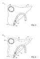
- FIG. 2 is a schematic drawing of the distal portion of catheter 14 showing contact force sensor 39.
- the figure shows and a first position (defined by solid lines) in which the distal tip 18 is not in contact with the endocardial surface of wall 37. In this position the signal from the sensor 39 can be accurately zeroed (provided no other catheter is nearby)
- a second position defined by broken lines, illustrates a contacting relationship between the distal tip 18 and the wall 37. In the latter condition, the signal from the sensor 39 cannot be accurately zeroed.
- operator-assisted contact force zeroing is often more comforting to the operator than the above-noted auto-zeroing techniques, as he has a degree of control. Confidence on the part of the operator in the accuracy of the zeroed state is important, as inaccurate contact force measurements may result in serious complications, such as perforation of the wall and hemopericardium. This is particularly true when ablating tissue in right atrium, the thinnest of the cardiac chambers.
- an operator-assisted zeroing visualization procedure is executed, e.g., by the processor 22.
- a map of the heart 12 is displayed on the monitor 29, and regions of the map that qualify for manual zeroing of the catheter become highlighted.
- the operator navigates the catheter 14 such that it is located in a highlighted region.
- the regions qualifying for zeroing in the blood pool are not too close (less than 3mm) to the endocardial surface or to other catheters. Closer proximity than 3 mm may produce system inaccuracies and trigger shaft proximity interference mechanisms found in some catheters.
- the blood pool may be defined by exploiting the algorithms described in the above-mentioned Application No. 14/010,697 . When more than one catheter is present, the algorithms may be modified by those skilled in the art to exclude their neighborhoods from the highlighted areas.
- the operator-assisted manual zeroing visualization procedure may alert the operator or even disable his ability to perform manual contact force zeroing when the catheter is detected, e.g., by the processor 22 in areas that are not suitable for zeroing, i.e., are not highlighted on the map displayed on the monitor 29.
- FIG. 3 is a schematic diagram of a cardiac chamber 41 illustrating zones varying in suitability for manual contact force zeroing, in accordance with an embodiment of the invention.
- a catheter 43 in the chamber 41 requires contact force zeroing.
- the chamber 41 is defined by myocardial wall 45 and an endocardial surface 47.
- zeroing is not reliable if performed when the catheter is too close to the endocardial surface 47 or another catheter 49.
- the catheter 43 must not be within a first exclusion zone 51 that extends from the endocardial surface 47 into the blood pool of the chamber 41.
- the exclusion zone 51 is typically 10 mm wide.
- the catheter 43 must not be within a second exclusion zone 53 about the catheter 49.
- the exclusion zone 53 is typically 3 mm wide. When the catheter 43 is not within the exclusion zones 51, 53 it is possible to manually zero the contact force sensor. However it is preferable to provide additional safety zones 55, 57 as buffers about the exclusion zones 51, 53, respectively.
- the zones 55, 57 are typically 3 mm thick. A careful operator will not manually zero the contact force sensor when the catheter 43 is within the zones 55, 57, but will require that the catheter 43be in a region 59 of the blood pool that is not within any of the zones 51, 53, 55, 57. The safe boundaries of the region 59 are thus 13 mm from the endocardial surface 47 and 6 mm from the catheter 49.
- Fig. 4 is a flow chart of a method of assistive manual contact force zeroing in a cardiac catheter, in accordance with an embodiment of the invention.
- the process steps are shown in a particular linear sequence in Fig. 4 for clarity of presentation. However, it will be evident that many of them can be performed in parallel, asynchronously, or in different orders. Those skilled in the art will also appreciate that a process could alternatively be represented as a number of interrelated states or events, e.g., in a state diagram. Moreover, not all illustrated process steps may be required to implement the process.
- catheterization of a cardiac chamber is accomplished conventionally.
- a contact force catheter and optionally other catheters are introduced into a cardiac chamber.
- a definition of the blood pool of the cardiac chamber is displayed as a first image.
- the blood pool is redrawn to exclude a first region of the blood pool adjacent the endocardial surface of the cardiac chamber, referred to herein as a first excluded region.
- the first excluded region is about 10 mm away from any tissue due to contraction and expansion of the heart ---.
- each catheter within the chamber other than the contact force catheter is surrounded by a respective spherical proximity zone, which constitutes a second excluded region.
- Steps 63, 65 may be accomplished using the procedures described in the above-mentioned Application No. 14/010,697 .
- a second image may be generated in which the first excluded region and the second included regions are highlighted.
- step 67 the first excluded region and the second exclusion regions defined on the second image in step 65 are subtracted from the first image that was produced in step 63, using standard image processing routines. A subtraction image is generated.
- the portion of the blood pool that remains on the subtraction image is referred to herein as a zero-qualified region, because it is suitable for manually zeroing the contact force sensor.
- the catheter is navigated by the operator and new images of the distal portion of the catheter and the blood pool are generated.
- the zero-qualified region may be highlighted to assist the operator.
- step 71 it is determined by evaluation of the new images if the catheter is in the zero-qualified region that was established at step 67. If the determination is negative, then control returns to step 69 and the catheter is repositioned.
- control proceeds to final step 73.
- the operator zeroes the contact force sensor, and the procedure ends.
- Fig. 5 is a screen display 75 obtained after completion of initial step 61 ( Fig. 4 ) in accordance with an embodiment of the invention.
- the screen display 75 shows blood pool 77 of a cardiac chamber 79 in which is found an ablation catheter 81 having a contact force sensor 83 at its distal end.
- a mapping catheter 85 is also present in the cardiac chamber 79.
- Fig. 6 is a screen display 87 obtained after completion of step 63 in accordance with an embodiment of the invention.
- the initial definition of the blood pool is highlighted and demarcated by a solid line 89.
- Portions of the blood pool 77 in a zone 91 external to the line 89 define the above-described first excluded region. Such portions are not suitable for contact force zeroing, as they are too close to the endocardial surface.
- the screen display 87 is an exemplary 2-dimensional projection of a 3-dimensional object, the display can be varied, to represent many views and projections in order to enable the operator to appreciate the location of the catheter anywhere within the interior of the cardiac chamber 79.
- Fig. 7 is a screen display 93 obtained after completion of step 65, in accordance with an embodiment of the invention.
- a spherical zone which appears roughly as a circle 95 in the 2-dimensional projection of Fig. 7 demarcates the above-described second excluded region about the catheter 85.
- respective exclusion regions of this sort would be demarcated about all other catheters found in the cardiac chamber 79 (other than the contact force catheter 81).
- Fig. 8 is a screen display 97 of a subtraction image obtained after completion of step 67 in accordance with an embodiment of the invention.
- the remaining portion of the blood pool 77, outlined by solid line 99 represents the zero-qualified region in which contact force zeroing of the contact force sensor 83 can be accomplished with confidence.
Abstract
Description
- This invention relates to cardiac catheterization. More particularly, this invention relates to determination of contact of a catheter with cardiac tissue.
- Cardiac arrhythmias, such as atrial fibrillation, occur when regions of cardiac tissue abnormally conduct electric signals to adjacent tissue, thereby disrupting the normal cardiac cycle and causing asynchronous rhythm.
- Procedures for treating arrhythmia include surgically disrupting the origin of the signals causing the arrhythmia, as well as disrupting the conducting pathway for such signals. By selectively ablating cardiac tissue by application of energy via a catheter, it is sometimes possible to cease or modify the propagation of unwanted electrical signals from one portion of the heart to another. The ablation process destroys the unwanted electrical pathways by formation of non-conducting lesions.
- Verification of physical electrode contact with the target tissue is important for controlling the delivery of ablation energy. Attempts in the art to verify electrode contact with the tissue have been extensive, and various techniques have been suggested. For example,
U.S. Patent No. 6,695,808 describes apparatus for treating a selected patient tissue or organ region. A probe has a contact surface that may be urged against the region, thereby creating contact pressure. A pressure transducer measures the contact pressure. This arrangement is said to meet the needs of procedures in which a medical instrument must be placed in firm but not excessive contact with an anatomical surface, by providing information to the user of the instrument that is indicative of the existence and magnitude of the contact force. - As another example,
U.S. U.S. Patent No. 6,241,724 describes methods for creating lesions in body tissue using segmented electrode assemblies. In one embodiment, an electrode assembly on a catheter carries pressure transducers, which sense contact with tissue and convey signals to a pressure contact module. The module identifies the electrode elements that are associated with the pressure transducer signals and directs an energy generator to convey radiofrequency energy to these elements, and not to other elements that are in contact only with blood. - A further example is presented in
U.S. Patent No. 6,915,149 . This patent describes a method for mapping a heart using a catheter having a tip electrode for measuring local electrical activity. In order to avoid artifacts that may arise from poor tip contact with the tissue, the contact pressure between the tip and the tissue is measured using a pressure sensor to ensure stable contact. -
U.S. Patent Application Publication 2007/0100332 describes systems and methods for assessing electrode-tissue contact for tissue ablation. An electromechanical sensor within the catheter shaft generates electrical signals corresponding to the amount of movement of the electrode within a distal portion of the catheter shaft. An output device receives the electrical signals for assessing a level of contact between the electrode and a tissue. - Impedance-based methods for assessing catheter-tissue contact that are known in the art typically rely on measurement of the magnitude of the impedance between an electrode on the catheter and a body-surface electrode. When the magnitude is below some threshold, the electrode is considered to be in contact with the tissue. This sort of binary contact indication may be unreliable, however, and is sensitive to changes in the impedance between the body-surface electrode and the skin.
-
U.S. Patent Application Publication Nos. 2008/0288038 and2008/0275465, both by Sauarav et al ., which are herein incorporated by reference, describe an electrode catheter system, which may comprise an electrode adapted to apply electric energy. A measurement circuit adapted to measure impedance may be implemented between the electrode and ground as the electrode approaches a target tissue. A processor or processing units may be implemented to determine a contact condition for the target tissue based at least in part on reactance of the impedance measured by the measurement circuit. In another embodiment, the contact condition may be based on the phase angle of the impedance. -
U.S. Patent Application Publication No. 2013/0172875 to Govari et al ., entitled "Contact Assessment Based on Phase Measurement", which is herein incorporated by reference, describes displaying intraoperative phase determinations of an electrical current passing between the ablation electrode and another electrode as an indicator of contact force between an ablation electrode and target tissue. - Today contact force catheters are commercially available, for example the THERMOCOOL® SMARTTOUCH™ Catheter, produced by Biosense Webster, Inc., 3333 Diamond Canyon Road, Diamond Bar, CA 91765.
- There is provided according to embodiments of the invention a method, which is carried out by inserting a probe having a contact force sensor into a cavity in a body of a subject, the cavity having a blood pool and an endocardial surface, generating an image of the blood pool, removing a portion of the blood pool from the image to retain a remaining portion of the blood pool thereon, making a determination from the image that the distal segment of the probe is within the remaining portion of the blood pool, and responsively to the determination manually zeroing the contact force sensor.
- According to one aspect of the method, the removed portion of the blood pool is adjacent the endocardial surface.
- According to a further aspect of the method, the removed portion of the blood pool is adjacent another probe.
- According to an additional aspect of the method, boundaries of the remaining portion of the blood pool are 3 mm from another probe in the cavity and 10 mm from the endocardial surface.
- According to a further aspect of the method, boundaries of the remaining portion of the blood pool are 6 mm from another probe in the cavity and 13 mm from the endocardial surface.
- There is further provided according to embodiments of the invention a method that is carried out by inserting a probe having a contact force sensor into a cavity in a body of a subject, the cavity having a blood pool and an endocardial surface. The method is further carried out by generating a first image of the blood pool, generating a second image to define an excluded region of the blood pool, generating subtraction images by subtracting the second image from the first image to define a zero-qualified region of the blood pool, and while generating the subtraction images navigating the probe within the cavity, until the distal portion is within the zero-qualified region.
- Another aspect of the method includes making a determination from the subtraction images that the distal portion is within the zero-qualified region, and responsively to the determination enabling manual zeroing of the contact force sensor.
- According to still another aspect of the method, a boundary of the other excluded region is at least 6 mm from another probe.
- According to an additional aspect of the method, the first image and the subtraction images include the other probe.
- There is further provided according to embodiments of the invention an apparatus, including a probe, configured for insertion into a body cavity having a blood pool, the probe including a contact force sensor for measuring a force applied to the contact force sensor and location sensors for detecting a location of the probe in the body cavity, and a processor, which is configured to receive a plurality of measurements from the contact force sensor. The processor is operative for generating an image of the blood pool, removing a portion of the blood pool from the image to retain a remaining portion of the blood pool thereon, and presenting a location of a distal segment of the probe on the image.
- According to yet another aspect of the apparatus, the processor is operative for making a determination from the image that the distal segment of the probe is within the remaining portion of the blood pool, and responsively to the determination enabling manual zeroing of the contact force sensor.
- For a better understanding of the present invention, reference is made to the detailed description of the invention, by way of example, which is to be read in conjunction with the following drawings, wherein like elements are given like reference numerals, and wherein:
-
Fig. 1 is a pictorial illustration of a system for performing medical procedures in accordance with an embodiment of the invention; -
Fig. 2 is a schematic drawing of the distal portion of the catheter shown inFig. 1 that includes a contact force sensor that can be adjusted in accordance with an embodiment of the invention; -
Fig. 3 is a schematic diagram of a cardiac chamber in accordance with an embodiment of the invention; -
Fig. 4 is a flow chart of a method of assistive manual contact force zeroing in a cardiac catheter in accordance with an embodiment of the invention; -
Fig. 5 is a screen display illustrating a phase of the method ofFig. 4 in accordance with an embodiment of the invention; -
Fig. 6 is a screen display illustrating a phase of the method ofFig. 4 in accordance with an embodiment of the invention; -
Fig. 7 is a screen display illustrating a phase of the method ofFig. 4 in accordance with an embodiment of the invention; and -
Fig. 8 is a screen display illustrating a phase of the method ofFig. 4 in accordance with an embodiment of the invention. - In the following description, numerous specific details are set forth in order to provide a thorough understanding of the various principles of the present invention. It will be apparent to one skilled in the art, however, that not all these details are necessarily needed for practicing the present invention. In this instance, well-known circuits, control logic, and the details of computer program instructions for conventional algorithms and processes have not been shown in detail in order not to obscure the general concepts unnecessarily.
- In a medical ablation procedure, such as ablation of heart tissue, it is extremely useful to be able to measure the force applied to the tissue while the tissue is being ablated. This is because the force applied is a key parameter governing the amount of tissue ablated for a given ablation energy input to the tissue. The ablation is typically provided by a probe comprising an ablation electrode at its distal end. To accurately measure a force exerted by the distal tip on the endocardium, the force sensor incorporated into the distal end of the probe is typically calibrated to a "zero level," also referred to herein as a baseline. The baseline is determined from measurements generated by the force sensor when the distal tip has minimal contact with any surface (and therefore there is essentially no effective force exerted on the distal tip). The baseline may be determined using the techniques disclosed in
U.S. Patent Application Publication No. 2012/0108988 to Ludwin et al ., which is herein incorporated by reference. Once the baseline is identified, the measurements from the force sensor can be used to provide a value of the force exerted. - But such force sensors known in the art typically drift., Even if the force exerted on the sensor is constant, readings from the sensor change. Such drift may be compensated for by zeroing the sensor periodically, typically before applying ablation energy. However, the zeroing of the sensor should only be applied if the sensor is not contacting or in proximity to tissue or other catheters, i.e., the sensor is in a state where the force on it is effectively zero.
- The force sensor is assumed to be in a zeroed state if over at least a predetermined interval of time force readings from the sensor change by less than a predetermined force limit. To ensure that the sensor is in the zeroed state, the probe having the force sensor is typically also assumed to change its location during the predetermined time interval by more than a predetermined location threshold.
- Commonly assigned Application No.
14/010,697 - The sensor is in a zeroed state where the force on it is effectively zero (such a state is typically achieved if the sensor is surrounded by blood in the heart chamber, and is not contacting a heart wall and the probe is not in proximity to another probe. Changes in proximity between probes may reduce the accuracy of the calibration values referred to above. In such cases, a probe may be assumed to be in the zeroed state if, in addition to the force condition described above, a measured value of the change in proximity to another probe is less than a predetermined proximity change threshold. In general, there is a high probability of accurately auto-zeroing the sensor when the sensor does not contact tissue. In addition, there is an extremely high probability of not auto-zeroing the sensor when the sensor does contact tissue.
- Turning now to the drawings, reference is initially made to
Fig. 1 , which is a pictorial illustration of asystem 10 for performing ablative procedures on aheart 12 of a living subject, which is constructed and operative in accordance with a disclosed embodiment of the invention. The system comprises acatheter 14, which is percutaneously inserted by anoperator 16 through the patient's vascular system into a chamber or vascular structure of theheart 12. Theoperator 16, who is typically a physician, brings the catheter'sdistal tip 18 into contact with the heart wall at an ablation target site. Optionally, Electrical activation maps may then be prepared, according to the methods disclosed inU.S. Patent Nos. 6,226,542 , and6,301,496 , and in commonly assignedU.S. Patent No. 6,892,091 , whose disclosures are herein incorporated by reference. One commercial product embodying elements of thesystem 10 is available as the CARTO ® 3 System, available from Biosense Webster. This system may be modified by those skilled in the art to embody the principles of the invention described herein. - Areas determined to be abnormal, for example by evaluation of the electrical activation maps, can be ablated by application of thermal energy, e.g., by passage of radiofrequency electrical current through wires in the catheter to one or more electrodes at the
distal tip 18, which apply the radiofrequency energy to the myocardium. The energy is absorbed in the tissue, heating it to a point (typically about 50°C) at which it permanently loses its electrical excitability. When successful, this procedure creates non-conducting lesions in the cardiac tissue, which disrupt the abnormal electrical pathway causing the arrhythmia. The principles of the invention can be applied to different heart chambers to treat many different cardiac arrhythmias. - The
catheter 14 typically comprises ahandle 20, having suitable controls on the handle to enable theoperator 16 to steer, position and orient the distal end of the catheter as desired for the ablation. To aid theoperator 16, the distal portion of thecatheter 14 contains position sensors (not shown) that provide signals to aprocessor 22, located in aconsole 24. Theprocessor 22 may fulfill several processing functions as described below. - Ablation energy and electrical signals can be conveyed to and from the
heart 12 through one ormore ablation electrodes 32 located at or near thedistal tip 18 viacable 34 to theconsole 24. Pacing signals and other control signals may be conveyed from theconsole 24 through thecable 34 and theelectrodes 32 to theheart 12.Sensing electrodes 33, also connected to theconsole 24 are disposed between theablation electrodes 32 and have connections to thecable 34. -
Wire connections 35 link theconsole 24 withbody surface electrodes 30 and other components of a positioning sub-system for measuring location and orientation coordinates of thecatheter 14. Theprocessor 22, or another processor (not shown) may be an element of the positioning subsystem. Theelectrodes 32 and thebody surface electrodes 30 may be used to measure tissue impedance at the ablation site as taught inU.S. Patent No. 7,536,218, issued to Govari et al ., which is herein incorporated by reference. A temperature sensor (not shown), typically a thermocouple or thermistor, may be mounted on or near each of theelectrodes 32. - The
console 24 typically contains one or moreablation power generators 25. Thecatheter 14 may be adapted to conduct ablative energy to the heart using any known ablation technique, e.g., radiofrequency energy, ultrasound energy, and laser-produced light energy. Such methods are disclosed in commonly assignedU.S. Patent Nos. 6,814,733 ,6,997,924 , and7,156,816 , which are herein incorporated by reference. - In one embodiment, the positioning subsystem comprises a magnetic position tracking arrangement that determines the position and orientation of the
catheter 14 by generating magnetic fields in a predefined working volume and sensing these fields at the catheter, using field generating coils 28. The positioning subsystemU.S. Patent No. 7,756,576 , which is hereby incorporated by reference, and in the above-notedU.S. Patent No. 7,536,218 . - As noted above, the
catheter 14 is coupled to theconsole 24, which enables theoperator 16 to observe and regulate the functions of thecatheter 14.Console 24 includes a processor, preferably a computer with appropriate signal processing circuits. The processor is coupled to drive amonitor 29. The signal processing circuits typically receive, amplify, filter and digitize signals from thecatheter 14, including signals generated by the above-noted sensors and a plurality of location sensing electrodes (not shown) located distally in thecatheter 14. The digitized signals are received and used by theconsole 24 and the positioning system to compute the position and orientation of thecatheter 14 and to analyze the electrical signals from the electrodes. - During the procedure, contact force between the
distal tip 18 orablation electrode 32 and thewall 37 may be measured using a position sensor in conjunction with theprocessor 22, or by any of the other techniques described above for verifying physical electrode contact with the target tissue. - Typically, the
system 10 includes other elements, which are not shown in the figures for the sake of simplicity. For example, thesystem 10 may include an electrocardiogram (ECG) monitor, coupled to receive signals from one or more body surface electrodes, so as to provide an ECG synchronization signal to theconsole 24. As mentioned above, thesystem 10 typically also includes a reference position sensor, either on an externally-applied reference patch attached to the exterior of the subject's body, or on an internally-placed catheter, which is inserted into theheart 12 maintained in a fixed position relative to theheart 12. Conventional pumps and lines for circulating liquids through thecatheter 14 for cooling the ablation site are provided. Thesystem 10 may receive image data from an external imaging modality, such as an MRI unit or the like and includes image processors that can be incorporated in or invoked by theprocessor 22 for generating and displaying images that are described below. - Reference is now made to
Fig. 2 , which is a schematic drawing of the distal portion ofcatheter 14 showingcontact force sensor 39. The figure shows and a first position (defined by solid lines) in which thedistal tip 18 is not in contact with the endocardial surface ofwall 37. In this position the signal from thesensor 39 can be accurately zeroed (provided no other catheter is nearby) A second position, defined by broken lines, illustrates a contacting relationship between thedistal tip 18 and thewall 37. In the latter condition, the signal from thesensor 39 cannot be accurately zeroed. - Reverting to
Fig. 1 , operator-assisted contact force zeroing is often more comforting to the operator than the above-noted auto-zeroing techniques, as he has a degree of control. Confidence on the part of the operator in the accuracy of the zeroed state is important, as inaccurate contact force measurements may result in serious complications, such as perforation of the wall and hemopericardium. This is particularly true when ablating tissue in right atrium, the thinnest of the cardiac chambers. To assure the operator that the contact force measurement is accurate, an operator-assisted zeroing visualization procedure is executed, e.g., by theprocessor 22. A map of theheart 12 is displayed on themonitor 29, and regions of the map that qualify for manual zeroing of the catheter become highlighted. The operator navigates thecatheter 14 such that it is located in a highlighted region. As noted above, the regions qualifying for zeroing in the blood pool are not too close (less than 3mm) to the endocardial surface or to other catheters. Closer proximity than 3 mm may produce system inaccuracies and trigger shaft proximity interference mechanisms found in some catheters. The blood pool may be defined by exploiting the algorithms described in the above-mentioned Application No.14/010,697 - The operator-assisted manual zeroing visualization procedure may alert the operator or even disable his ability to perform manual contact force zeroing when the catheter is detected, e.g., by the
processor 22 in areas that are not suitable for zeroing, i.e., are not highlighted on the map displayed on themonitor 29. - Reference is now made to
Fig. 3 , which is a schematic diagram of acardiac chamber 41 illustrating zones varying in suitability for manual contact force zeroing, in accordance with an embodiment of the invention. Acatheter 43 in thechamber 41 requires contact force zeroing. Thechamber 41 is defined bymyocardial wall 45 and anendocardial surface 47. As noted above zeroing is not reliable if performed when the catheter is too close to theendocardial surface 47 or anothercatheter 49. Thecatheter 43 must not be within afirst exclusion zone 51 that extends from theendocardial surface 47 into the blood pool of thechamber 41. As noted above, theexclusion zone 51 is typically 10 mm wide. Moreover, thecatheter 43 must not be within asecond exclusion zone 53 about thecatheter 49. Theexclusion zone 53 is typically 3 mm wide. When thecatheter 43 is not within theexclusion zones additional safety zones exclusion zones zones catheter 43 is within thezones region 59 of the blood pool that is not within any of thezones region 59 are thus 13 mm from theendocardial surface 47 and 6 mm from thecatheter 49. - Reference is now made to
Fig. 4 , which is a flow chart of a method of assistive manual contact force zeroing in a cardiac catheter, in accordance with an embodiment of the invention. The process steps are shown in a particular linear sequence inFig. 4 for clarity of presentation. However, it will be evident that many of them can be performed in parallel, asynchronously, or in different orders. Those skilled in the art will also appreciate that a process could alternatively be represented as a number of interrelated states or events, e.g., in a state diagram. Moreover, not all illustrated process steps may be required to implement the process. - At
initial step 61 catheterization of a cardiac chamber is accomplished conventionally. A contact force catheter and optionally other catheters are introduced into a cardiac chamber. - Next, at
step 63, a definition of the blood pool of the cardiac chamber is displayed as a first image. - Next, at
step 65, The blood pool is redrawn to exclude a first region of the blood pool adjacent the endocardial surface of the cardiac chamber, referred to herein as a first excluded region. Typically, the first excluded region is about 10 mm away from any tissue due to contraction and expansion of the heart ---. Furthermore, each catheter within the chamber other than the contact force catheter is surrounded by a respective spherical proximity zone, which constitutes a second excluded region.Steps 14/010,697 - Next, at
step 67, the first excluded region and the second exclusion regions defined on the second image instep 65 are subtracted from the first image that was produced instep 63, using standard image processing routines. A subtraction image is generated. The portion of the blood pool that remains on the subtraction image is referred to herein as a zero-qualified region, because it is suitable for manually zeroing the contact force sensor. - Referring again to
Fig. 4 , next, atstep 69, the catheter is navigated by the operator and new images of the distal portion of the catheter and the blood pool are generated. The zero-qualified region may be highlighted to assist the operator. - Next, at
decision step 71, it is determined by evaluation of the new images if the catheter is in the zero-qualified region that was established atstep 67. If the determination is negative, then control returns to step 69 and the catheter is repositioned. - If the determination at
decision step 71 is affirmative then control proceeds tofinal step 73. The operator zeroes the contact force sensor, and the procedure ends. - Reference is now made to
Fig. 5 , which is ascreen display 75 obtained after completion of initial step 61 (Fig. 4 ) in accordance with an embodiment of the invention. Thescreen display 75 showsblood pool 77 of acardiac chamber 79 in which is found anablation catheter 81 having acontact force sensor 83 at its distal end. Amapping catheter 85 is also present in thecardiac chamber 79. - Reference is now made to
Fig. 6 , which is ascreen display 87 obtained after completion ofstep 63 in accordance with an embodiment of the invention. The initial definition of the blood pool is highlighted and demarcated by asolid line 89. Portions of theblood pool 77 in azone 91 external to theline 89 define the above-described first excluded region. Such portions are not suitable for contact force zeroing, as they are too close to the endocardial surface. It will be appreciated that while thescreen display 87 is an exemplary 2-dimensional projection of a 3-dimensional object, the display can be varied, to represent many views and projections in order to enable the operator to appreciate the location of the catheter anywhere within the interior of thecardiac chamber 79. - Reference is now made to
Fig. 7 , which is ascreen display 93 obtained after completion ofstep 65, in accordance with an embodiment of the invention. A spherical zone, which appears roughly as acircle 95 in the 2-dimensional projection ofFig. 7 demarcates the above-described second excluded region about thecatheter 85. Although not shown inFig. 7 , respective exclusion regions of this sort would be demarcated about all other catheters found in the cardiac chamber 79 (other than the contact force catheter 81). - Reference is now made to
Fig. 8 , which is ascreen display 97 of a subtraction image obtained after completion ofstep 67 in accordance with an embodiment of the invention. The remaining portion of theblood pool 77, outlined bysolid line 99 represents the zero-qualified region in which contact force zeroing of thecontact force sensor 83 can be accomplished with confidence. - The procedure shown in
Fig. 4 is represented Listing 1 by pseudocode, which can be implemented on an image processor. -
      Create the chamber volume and draw all catheters in
      CatheterList
      BloodPoolVolume = Find Blood pool()
      Mark BloodPoolVolume volume with color;
      For each Catheter in CatheterList
      If Catheter not ContactForceCatheter then
         Mark catheter exclusion zone with VolumetricSphere
      End If
      Next Catheter
      Calculate ManualZeroSuggestion as
      BloodPoolVolume - Union of VolumetricSpheres
- 1. A method, comprising the steps of:
- inserting a probe having a distal segment and a contact force sensor into a cavity in a body of a subject, the cavity having a blood pool and an endocardial surface;
- generating an image of the blood pool;
- removing a portion of the blood pool from the image to retain a remaining portion of the blood pool thereon;
- making a determination from the image that the distal segment of the probe is within the remaining portion of the blood pool; and
- responsively to the determination manually zeroing the contact force sensor.
- 2. The method according to aspect 1, wherein the removed portion of the blood pool is adjacent the endocardial surface.
- 3. The method according to aspect 1, wherein the removed portion of the blood pool is adjacent another probe.
- 4. The method according to aspect 1, wherein boundaries of the remaining portion of the blood pool are 3 mm from another probe in the cavity and 10 mm from the endocardial surface.
- 5. The method according to aspect 1, wherein boundaries of the remaining portion of the blood pool are 6 mm from another probe in the cavity and 13 mm from the endocardial surface.
- 6. A method, comprising the steps of:
- inserting a probe having a distal portion and a contact force sensor into a cavity in a body of a subject, the cavity having a blood pool and an endocardial surface;
- generating a first image of the blood pool;
- generating a second image to define an excluded region of the blood pool;
- generating subtraction images by subtracting the second image from the first image to define a zero-qualified region of the blood pool; and
- while generating the subtraction images navigating the probe within the cavity; until the distal portion is within the zero-qualified region.
- 7. The method according to aspect 6, further comprising the steps of:
- making a determination from the subtraction images that the distal portion is within the zero-qualified region; and
- responsively to the determination enabling manual zeroing of the contact force sensor.
- 8. The method according to aspect 6, wherein margins of the first image are at least 10 mm from the endocardial surface.
- 9. The method according to aspect 6, wherein margins of the first image are at least 13 mm from the endocardial surface.
- 10. The method according to aspect 6, further comprising the steps of:
- inserting another probe into the cavity,
- including on the second image another excluded region about the other probe.
- 11. The method according to
aspect 10, wherein a boundary of the other excluded region is at least 3 mm from another probe. - 12. The method according to
aspect 10, wherein a boundary of the other excluded region is at least 6 mm from another probe. - 13. The method according to
aspect 10, wherein the first image and the subtraction images include the other probe.
Claims (8)
- An apparatus, comprising:a probe, configured for insertion into a body cavity having a blood pool of a patient and comprising a contact force sensor for measuring a force applied to the contact force sensor and location sensors for detecting a location of the probe in the body cavity; anda processor, which is configured to receive a plurality of measurements from the contact force sensor and operative for:generating an image of the blood pool;removing a portion of the blood pool from the image to retain a remaining portion of the blood pool thereon; andpresenting a location of a distal segment of the probe on the image.
- The apparatus according to claim 1, wherein the processor is operative for:making a determination from the image that the distal segment of the probe is within the remaining portion of the blood pool; andresponsively to the determination enabling manual zeroing of the contact force sensor.
- The apparatus according to claim 1, wherein the removed portion comprises a 10 mm zone adjacent an endocardial surface of a heart.
- The apparatus according to claim 1, wherein the removed portion comprises a 10 - 13 mm zone adjacent an endocardial surface of a heart.
- The apparatus according to claim 1, further comprising the step of:inserting another probe into the body cavity, wherein the removed portion includes a region about the other probe.
- The apparatus according to claim 5, wherein the region about the other probe is 3 mm in thickness.
- The apparatus according to claim 5, wherein the region about the other probe is 3 - 6 mm in thickness.
- The apparatus according to claim 5, wherein the image includes the other probe.
Applications Claiming Priority (1)
| Application Number | Priority Date | Filing Date | Title |
|---|---|---|---|
| US14/315,408 US10327744B2 (en) | 2014-06-26 | 2014-06-26 | Assistive manual zeroing visualization |
Publications (2)
| Publication Number | Publication Date |
|---|---|
| EP2959856A1 true EP2959856A1 (en) | 2015-12-30 |
| EP2959856B1 EP2959856B1 (en) | 2019-10-02 |
Family
ID=53491333
Family Applications (1)
| Application Number | Title | Priority Date | Filing Date |
|---|---|---|---|
| EP15173886.1A Active EP2959856B1 (en) | 2014-06-26 | 2015-06-25 | Assistive manual zeroing visualization |
Country Status (8)
| Country | Link |
|---|---|
| US (2) | US10327744B2 (en) |
| EP (1) | EP2959856B1 (en) |
| JP (1) | JP6576707B2 (en) |
| CN (1) | CN105266893B (en) |
| AU (2) | AU2015203335B2 (en) |
| CA (1) | CA2894930C (en) |
| ES (1) | ES2762212T3 (en) |
| IL (1) | IL238902B (en) |
Families Citing this family (3)
| Publication number | Priority date | Publication date | Assignee | Title |
|---|---|---|---|---|
| US10327744B2 (en) * | 2014-06-26 | 2019-06-25 | Biosense Webster (Israel) Ltd | Assistive manual zeroing visualization |
| US11589873B2 (en) * | 2018-12-31 | 2023-02-28 | Biosense Webster (Israel) Ltd. | Occlusion detection by pressure measurement |
| KR20230155184A (en) | 2022-05-03 | 2023-11-10 | 한국에너지기술연구원 | Flame velocity control gas burner to prevent flashback and controlling method thereof |
Citations (17)
| Publication number | Priority date | Publication date | Assignee | Title |
|---|---|---|---|---|
| US6226542B1 (en) | 1998-07-24 | 2001-05-01 | Biosense, Inc. | Three-dimensional reconstruction of intrabody organs |
| US6241724B1 (en) | 1993-10-19 | 2001-06-05 | Ep Technologies, Inc. | Systems and methods for creating lesions in body tissue using segmented electrode assemblies |
| US6301496B1 (en) | 1998-07-24 | 2001-10-09 | Biosense, Inc. | Vector mapping of three-dimensionally reconstructed intrabody organs and method of display |
| US6695808B2 (en) | 2000-03-23 | 2004-02-24 | Scimed Life Systems, Inc. | Pressure sensor for therapeutic delivery device and method |
| US6814733B2 (en) | 2002-01-31 | 2004-11-09 | Biosense, Inc. | Radio frequency pulmonary vein isolation |
| US6892091B1 (en) | 2000-02-18 | 2005-05-10 | Biosense, Inc. | Catheter, method and apparatus for generating an electrical map of a chamber of the heart |
| US6915149B2 (en) | 1996-01-08 | 2005-07-05 | Biosense, Inc. | Method of pacing a heart using implantable device |
| US6997924B2 (en) | 2002-09-17 | 2006-02-14 | Biosense Inc. | Laser pulmonary vein isolation |
| US7156816B2 (en) | 2002-11-26 | 2007-01-02 | Biosense, Inc. | Ultrasound pulmonary vein isolation |
| US20070100332A1 (en) | 2005-10-27 | 2007-05-03 | St. Jude Medical, Atrial Fibrillation Division, Inc. | Systems and methods for electrode contact assessment |
| US20080275465A1 (en) | 2005-12-06 | 2008-11-06 | Saurav Paul | Design of Handle Set for Ablation Catheter with Indicators of Catheter and Tissue Parameters |
| US7536218B2 (en) | 2005-07-15 | 2009-05-19 | Biosense Webster, Inc. | Hybrid magnetic-based and impedance-based position sensing |
| US7756576B2 (en) | 2005-08-26 | 2010-07-13 | Biosense Webster, Inc. | Position sensing and detection of skin impedance |
| US20120108988A1 (en) | 2010-11-03 | 2012-05-03 | Doron Moshe Ludwin | Zero-drift detection and correction in contact force measurements |
| US20120158011A1 (en) * | 2010-12-16 | 2012-06-21 | Sandhu Kulbir S | Proximity sensor interface in a robotic catheter system |
| EP2574278A2 (en) * | 2011-09-30 | 2013-04-03 | Biosense Webster (Israel), Ltd. | In-vivo calibration of contact force-sensing catheters |
| US20130172875A1 (en) | 2012-01-04 | 2013-07-04 | Assaf Govari | Contact assessment based on phase measurement |
Family Cites Families (24)
| Publication number | Priority date | Publication date | Assignee | Title |
|---|---|---|---|---|
| ES2227718T3 (en) * | 1996-10-04 | 2005-04-01 | United States Surgical Corporation | CIRCULATORY SUPPORT SYSTEM. |
| JP2002534191A (en) * | 1999-01-04 | 2002-10-15 | コーニンクレッカ フィリップス エレクトロニクス エヌ ヴィ | Method, system and apparatus for processing an image representing a tubular structure and constructing a path through the structure |
| JP2000300579A (en) * | 1999-04-26 | 2000-10-31 | Olympus Optical Co Ltd | Multifunctional manipulator |
| US7285117B2 (en) * | 2002-03-15 | 2007-10-23 | Boston Scientific Scimed, Inc. | Medical device control systems |
| US7711160B2 (en) | 2003-05-28 | 2010-05-04 | Siemens Medical Solutions Usa, Inc. | Automatic optimal view determination for cardiac acquisitions |
| CN100573594C (en) * | 2003-05-28 | 2009-12-23 | 美国西门子医疗解决公司 | Being used for the automatic optimal view that cardiac image obtains determines |
| US8657814B2 (en) * | 2005-08-22 | 2014-02-25 | Medtronic Ablation Frontiers Llc | User interface for tissue ablation system |
| CN101247766B (en) * | 2005-08-25 | 2011-03-02 | 皇家飞利浦电子股份有限公司 | System for electrophysiology regaining support to continue line and ring ablations |
| US10376314B2 (en) | 2006-07-14 | 2019-08-13 | Neuwave Medical, Inc. | Energy delivery systems and uses thereof |
| CN101511295B (en) * | 2006-07-14 | 2012-09-05 | 纽华沃医药公司 | Energy delivery systems and uses thereof |
| DE102007018015A1 (en) | 2007-04-17 | 2008-10-23 | Bayer Materialscience Ag | Preparation of uretdione group-containing polyisocyanates |
| US8315690B2 (en) * | 2007-10-02 | 2012-11-20 | General Electric Company | Dynamic reference method and system for interventional procedures |
| EP2197377B1 (en) * | 2007-11-16 | 2017-11-01 | St. Jude Medical, Atrial Fibrillation Division, Inc. | Device for real-time lesion estimation during ablation |
| US10299753B2 (en) * | 2007-11-29 | 2019-05-28 | Biosense Webster, Inc. | Flashlight view of an anatomical structure |
| US8343096B2 (en) | 2008-03-27 | 2013-01-01 | St. Jude Medical, Atrial Fibrillation Division, Inc. | Robotic catheter system |
| CA2703347C (en) * | 2009-05-08 | 2016-10-04 | Endosense Sa | Method and apparatus for controlling lesion size in catheter-based ablation treatment |
| EP2440131B1 (en) | 2009-06-08 | 2018-04-04 | MRI Interventions, Inc. | Mri-guided interventional systems that can track and generate dynamic visualizations of flexible intrabody devices in near real time |
| US10835207B2 (en) * | 2009-12-23 | 2020-11-17 | Biosense Webster (Israel) Ltd. | Fast anatomical mapping using ultrasound images |
| JP5670145B2 (en) * | 2010-10-14 | 2015-02-18 | 株式会社東芝 | Medical image processing apparatus and control program |
| US8777857B2 (en) * | 2011-04-14 | 2014-07-15 | St. Jude Medical, Inc. | Single transducer with angular orientation for lesion feedback in ablation catheter |
| US9760988B2 (en) | 2011-05-10 | 2017-09-12 | Koninklijke Philips N.V. | Myocardial clusterification and orientation |
| WO2013096803A2 (en) | 2011-12-21 | 2013-06-27 | Neuwave Medical, Inc. | Energy delivery systems and uses thereof |
| US9775578B2 (en) * | 2013-08-12 | 2017-10-03 | Biosense Webster (Israel) Ltd. | Unmapped region visualization |
| US10327744B2 (en) * | 2014-06-26 | 2019-06-25 | Biosense Webster (Israel) Ltd | Assistive manual zeroing visualization |
-
2014
- 2014-06-26 US US14/315,408 patent/US10327744B2/en active Active
-
2015
- 2015-05-19 IL IL238902A patent/IL238902B/en active IP Right Grant
- 2015-06-17 AU AU2015203335A patent/AU2015203335B2/en not_active Ceased
- 2015-06-18 CA CA2894930A patent/CA2894930C/en active Active
- 2015-06-25 EP EP15173886.1A patent/EP2959856B1/en active Active
- 2015-06-25 JP JP2015127357A patent/JP6576707B2/en active Active
- 2015-06-25 ES ES15173886T patent/ES2762212T3/en active Active
- 2015-06-26 CN CN201510363263.3A patent/CN105266893B/en active Active
-
2019
- 2019-05-08 US US16/406,341 patent/US11771407B2/en active Active
- 2019-07-08 AU AU2019204909A patent/AU2019204909B2/en not_active Ceased
Patent Citations (19)
| Publication number | Priority date | Publication date | Assignee | Title |
|---|---|---|---|---|
| US6241724B1 (en) | 1993-10-19 | 2001-06-05 | Ep Technologies, Inc. | Systems and methods for creating lesions in body tissue using segmented electrode assemblies |
| US6915149B2 (en) | 1996-01-08 | 2005-07-05 | Biosense, Inc. | Method of pacing a heart using implantable device |
| US6226542B1 (en) | 1998-07-24 | 2001-05-01 | Biosense, Inc. | Three-dimensional reconstruction of intrabody organs |
| US6301496B1 (en) | 1998-07-24 | 2001-10-09 | Biosense, Inc. | Vector mapping of three-dimensionally reconstructed intrabody organs and method of display |
| US6892091B1 (en) | 2000-02-18 | 2005-05-10 | Biosense, Inc. | Catheter, method and apparatus for generating an electrical map of a chamber of the heart |
| US6695808B2 (en) | 2000-03-23 | 2004-02-24 | Scimed Life Systems, Inc. | Pressure sensor for therapeutic delivery device and method |
| US6814733B2 (en) | 2002-01-31 | 2004-11-09 | Biosense, Inc. | Radio frequency pulmonary vein isolation |
| US6997924B2 (en) | 2002-09-17 | 2006-02-14 | Biosense Inc. | Laser pulmonary vein isolation |
| US7156816B2 (en) | 2002-11-26 | 2007-01-02 | Biosense, Inc. | Ultrasound pulmonary vein isolation |
| US7536218B2 (en) | 2005-07-15 | 2009-05-19 | Biosense Webster, Inc. | Hybrid magnetic-based and impedance-based position sensing |
| US7756576B2 (en) | 2005-08-26 | 2010-07-13 | Biosense Webster, Inc. | Position sensing and detection of skin impedance |
| US20070100332A1 (en) | 2005-10-27 | 2007-05-03 | St. Jude Medical, Atrial Fibrillation Division, Inc. | Systems and methods for electrode contact assessment |
| US20080275465A1 (en) | 2005-12-06 | 2008-11-06 | Saurav Paul | Design of Handle Set for Ablation Catheter with Indicators of Catheter and Tissue Parameters |
| US20080288038A1 (en) | 2005-12-06 | 2008-11-20 | Saurav Paul | Method for Displaying Catheter Electrode-Tissue Contact in Electro-Anatomic Mapping and Navigation System |
| US20120108988A1 (en) | 2010-11-03 | 2012-05-03 | Doron Moshe Ludwin | Zero-drift detection and correction in contact force measurements |
| EP2449996A2 (en) * | 2010-11-03 | 2012-05-09 | Biosense Webster (Israel), Ltd. | Zero-drift detection and correction in contact force measurements |
| US20120158011A1 (en) * | 2010-12-16 | 2012-06-21 | Sandhu Kulbir S | Proximity sensor interface in a robotic catheter system |
| EP2574278A2 (en) * | 2011-09-30 | 2013-04-03 | Biosense Webster (Israel), Ltd. | In-vivo calibration of contact force-sensing catheters |
| US20130172875A1 (en) | 2012-01-04 | 2013-07-04 | Assaf Govari | Contact assessment based on phase measurement |
Also Published As
| Publication number | Publication date |
|---|---|
| ES2762212T3 (en) | 2020-05-22 |
| US11771407B2 (en) | 2023-10-03 |
| IL238902B (en) | 2020-04-30 |
| AU2019204909B2 (en) | 2020-10-22 |
| US10327744B2 (en) | 2019-06-25 |
| CN105266893B (en) | 2020-05-01 |
| US20190261969A1 (en) | 2019-08-29 |
| CA2894930C (en) | 2022-07-05 |
| AU2015203335B2 (en) | 2019-07-11 |
| EP2959856B1 (en) | 2019-10-02 |
| CN105266893A (en) | 2016-01-27 |
| JP6576707B2 (en) | 2019-09-18 |
| US20150374448A1 (en) | 2015-12-31 |
| AU2019204909A1 (en) | 2019-07-25 |
| AU2015203335A1 (en) | 2016-01-21 |
| JP2016007544A (en) | 2016-01-18 |
| IL238902A0 (en) | 2016-02-29 |
| CA2894930A1 (en) | 2015-12-26 |
Similar Documents
| Publication | Publication Date | Title |
|---|---|---|
| US11324550B2 (en) | System and method for assessing effective delivery of ablation therapy | |
| US9173586B2 (en) | System and method for assessing coupling between an electrode and tissue | |
| US8449535B2 (en) | System and method for assessing coupling between an electrode and tissue | |
| EP2612612B1 (en) | Contact assessment based on phase measurement | |
| US20090275827A1 (en) | System and method for assessing the proximity of an electrode to tissue in a body | |
| AU2016253611A1 (en) | Symmetric short contact force sensor with four coils | |
| AU2019204909B2 (en) | Assistive manual zeroing visualization | |
| EP2842508B1 (en) | Determining non-contact state for a catheter | |
| US20150066021A1 (en) | Determining absence of contact for a catheter | |
| CN116138874A (en) | Mapping system with real-time electrogram overlay | |
| CN115804606A (en) | Distal end assembly guide | |
| JP7353919B2 (en) | Use of Radio Frequency (RF) Transmission System to Find Openings in Tissue Walls | |
| CN116407260A (en) | Visual mapping system |
Legal Events
| Date | Code | Title | Description |
|---|---|---|---|
| PUAI | Public reference made under article 153(3) epc to a published international application that has entered the european phase |
Free format text: ORIGINAL CODE: 0009012 |
|
| AK | Designated contracting states |
Kind code of ref document: A1 Designated state(s): AL AT BE BG CH CY CZ DE DK EE ES FI FR GB GR HR HU IE IS IT LI LT LU LV MC MK MT NL NO PL PT RO RS SE SI SK SM TR |
|
| AX | Request for extension of the european patent |
Extension state: BA ME |
|
| 17P | Request for examination filed |
Effective date: 20160624 |
|
| RBV | Designated contracting states (corrected) |
Designated state(s): AL AT BE BG CH CY CZ DE DK EE ES FI FR GB GR HR HU IE IS IT LI LT LU LV MC MK MT NL NO PL PT RO RS SE SI SK SM TR |
|
| GRAP | Despatch of communication of intention to grant a patent |
Free format text: ORIGINAL CODE: EPIDOSNIGR1 |
|
| STAA | Information on the status of an ep patent application or granted ep patent |
Free format text: STATUS: GRANT OF PATENT IS INTENDED |
|
| RIC1 | Information provided on ipc code assigned before grant |
Ipc: A61B 90/00 20160101ALI20190304BHEP Ipc: A61B 34/20 20160101ALI20190304BHEP Ipc: A61B 18/14 20060101AFI20190304BHEP |
|
| INTG | Intention to grant announced |
Effective date: 20190325 |
|
| GRAS | Grant fee paid |
Free format text: ORIGINAL CODE: EPIDOSNIGR3 |
|
| GRAA | (expected) grant |
Free format text: ORIGINAL CODE: 0009210 |
|
| STAA | Information on the status of an ep patent application or granted ep patent |
Free format text: STATUS: THE PATENT HAS BEEN GRANTED |
|
| AK | Designated contracting states |
Kind code of ref document: B1 Designated state(s): AL AT BE BG CH CY CZ DE DK EE ES FI FR GB GR HR HU IE IS IT LI LT LU LV MC MK MT NL NO PL PT RO RS SE SI SK SM TR |
|
| REG | Reference to a national code |
Ref country code: GB Ref legal event code: FG4D |
|
| REG | Reference to a national code |
Ref country code: CH Ref legal event code: EP Ref country code: CH Ref legal event code: NV Representative=s name: E. BLUM AND CO. AG PATENT- UND MARKENANWAELTE , CH Ref country code: AT Ref legal event code: REF Ref document number: 1185337 Country of ref document: AT Kind code of ref document: T Effective date: 20191015 |
|
| REG | Reference to a national code |
Ref country code: DE Ref legal event code: R096 Ref document number: 602015038943 Country of ref document: DE |
|
| REG | Reference to a national code |
Ref country code: IE Ref legal event code: FG4D |
|
| REG | Reference to a national code |
Ref country code: NL Ref legal event code: FP |
|
| REG | Reference to a national code |
Ref country code: LT Ref legal event code: MG4D |
|
| REG | Reference to a national code |
Ref country code: AT Ref legal event code: MK05 Ref document number: 1185337 Country of ref document: AT Kind code of ref document: T Effective date: 20191002 |
|
| PG25 | Lapsed in a contracting state [announced via postgrant information from national office to epo] |
Ref country code: PL Free format text: LAPSE BECAUSE OF FAILURE TO SUBMIT A TRANSLATION OF THE DESCRIPTION OR TO PAY THE FEE WITHIN THE PRESCRIBED TIME-LIMIT Effective date: 20191002 Ref country code: LT Free format text: LAPSE BECAUSE OF FAILURE TO SUBMIT A TRANSLATION OF THE DESCRIPTION OR TO PAY THE FEE WITHIN THE PRESCRIBED TIME-LIMIT Effective date: 20191002 Ref country code: AT Free format text: LAPSE BECAUSE OF FAILURE TO SUBMIT A TRANSLATION OF THE DESCRIPTION OR TO PAY THE FEE WITHIN THE PRESCRIBED TIME-LIMIT Effective date: 20191002 Ref country code: NO Free format text: LAPSE BECAUSE OF FAILURE TO SUBMIT A TRANSLATION OF THE DESCRIPTION OR TO PAY THE FEE WITHIN THE PRESCRIBED TIME-LIMIT Effective date: 20200102 Ref country code: GR Free format text: LAPSE BECAUSE OF FAILURE TO SUBMIT A TRANSLATION OF THE DESCRIPTION OR TO PAY THE FEE WITHIN THE PRESCRIBED TIME-LIMIT Effective date: 20200103 Ref country code: PT Free format text: LAPSE BECAUSE OF FAILURE TO SUBMIT A TRANSLATION OF THE DESCRIPTION OR TO PAY THE FEE WITHIN THE PRESCRIBED TIME-LIMIT Effective date: 20200203 Ref country code: BG Free format text: LAPSE BECAUSE OF FAILURE TO SUBMIT A TRANSLATION OF THE DESCRIPTION OR TO PAY THE FEE WITHIN THE PRESCRIBED TIME-LIMIT Effective date: 20200102 Ref country code: FI Free format text: LAPSE BECAUSE OF FAILURE TO SUBMIT A TRANSLATION OF THE DESCRIPTION OR TO PAY THE FEE WITHIN THE PRESCRIBED TIME-LIMIT Effective date: 20191002 Ref country code: SE Free format text: LAPSE BECAUSE OF FAILURE TO SUBMIT A TRANSLATION OF THE DESCRIPTION OR TO PAY THE FEE WITHIN THE PRESCRIBED TIME-LIMIT Effective date: 20191002 Ref country code: LV Free format text: LAPSE BECAUSE OF FAILURE TO SUBMIT A TRANSLATION OF THE DESCRIPTION OR TO PAY THE FEE WITHIN THE PRESCRIBED TIME-LIMIT Effective date: 20191002 |
|
| REG | Reference to a national code |
Ref country code: ES Ref legal event code: FG2A Ref document number: 2762212 Country of ref document: ES Kind code of ref document: T3 Effective date: 20200522 |
|
| PG25 | Lapsed in a contracting state [announced via postgrant information from national office to epo] |
Ref country code: RS Free format text: LAPSE BECAUSE OF FAILURE TO SUBMIT A TRANSLATION OF THE DESCRIPTION OR TO PAY THE FEE WITHIN THE PRESCRIBED TIME-LIMIT Effective date: 20191002 Ref country code: IS Free format text: LAPSE BECAUSE OF FAILURE TO SUBMIT A TRANSLATION OF THE DESCRIPTION OR TO PAY THE FEE WITHIN THE PRESCRIBED TIME-LIMIT Effective date: 20200224 Ref country code: HR Free format text: LAPSE BECAUSE OF FAILURE TO SUBMIT A TRANSLATION OF THE DESCRIPTION OR TO PAY THE FEE WITHIN THE PRESCRIBED TIME-LIMIT Effective date: 20191002 Ref country code: CZ Free format text: LAPSE BECAUSE OF FAILURE TO SUBMIT A TRANSLATION OF THE DESCRIPTION OR TO PAY THE FEE WITHIN THE PRESCRIBED TIME-LIMIT Effective date: 20191002 |
|
| PG25 | Lapsed in a contracting state [announced via postgrant information from national office to epo] |
Ref country code: AL Free format text: LAPSE BECAUSE OF FAILURE TO SUBMIT A TRANSLATION OF THE DESCRIPTION OR TO PAY THE FEE WITHIN THE PRESCRIBED TIME-LIMIT Effective date: 20191002 |
|
| REG | Reference to a national code |
Ref country code: DE Ref legal event code: R097 Ref document number: 602015038943 Country of ref document: DE |
|
| PG2D | Information on lapse in contracting state deleted |
Ref country code: IS |
|
| PG25 | Lapsed in a contracting state [announced via postgrant information from national office to epo] |
Ref country code: EE Free format text: LAPSE BECAUSE OF FAILURE TO SUBMIT A TRANSLATION OF THE DESCRIPTION OR TO PAY THE FEE WITHIN THE PRESCRIBED TIME-LIMIT Effective date: 20191002 Ref country code: DK Free format text: LAPSE BECAUSE OF FAILURE TO SUBMIT A TRANSLATION OF THE DESCRIPTION OR TO PAY THE FEE WITHIN THE PRESCRIBED TIME-LIMIT Effective date: 20191002 Ref country code: RO Free format text: LAPSE BECAUSE OF FAILURE TO SUBMIT A TRANSLATION OF THE DESCRIPTION OR TO PAY THE FEE WITHIN THE PRESCRIBED TIME-LIMIT Effective date: 20191002 Ref country code: IS Free format text: LAPSE BECAUSE OF FAILURE TO SUBMIT A TRANSLATION OF THE DESCRIPTION OR TO PAY THE FEE WITHIN THE PRESCRIBED TIME-LIMIT Effective date: 20200202 |
|
| PLBE | No opposition filed within time limit |
Free format text: ORIGINAL CODE: 0009261 |
|
| STAA | Information on the status of an ep patent application or granted ep patent |
Free format text: STATUS: NO OPPOSITION FILED WITHIN TIME LIMIT |
|
| PG25 | Lapsed in a contracting state [announced via postgrant information from national office to epo] |
Ref country code: SK Free format text: LAPSE BECAUSE OF FAILURE TO SUBMIT A TRANSLATION OF THE DESCRIPTION OR TO PAY THE FEE WITHIN THE PRESCRIBED TIME-LIMIT Effective date: 20191002 Ref country code: SM Free format text: LAPSE BECAUSE OF FAILURE TO SUBMIT A TRANSLATION OF THE DESCRIPTION OR TO PAY THE FEE WITHIN THE PRESCRIBED TIME-LIMIT Effective date: 20191002 |
|
| 26N | No opposition filed |
Effective date: 20200703 |
|
| PG25 | Lapsed in a contracting state [announced via postgrant information from national office to epo] |
Ref country code: SI Free format text: LAPSE BECAUSE OF FAILURE TO SUBMIT A TRANSLATION OF THE DESCRIPTION OR TO PAY THE FEE WITHIN THE PRESCRIBED TIME-LIMIT Effective date: 20191002 |
|
| PG25 | Lapsed in a contracting state [announced via postgrant information from national office to epo] |
Ref country code: MC Free format text: LAPSE BECAUSE OF FAILURE TO SUBMIT A TRANSLATION OF THE DESCRIPTION OR TO PAY THE FEE WITHIN THE PRESCRIBED TIME-LIMIT Effective date: 20191002 |
|
| PG25 | Lapsed in a contracting state [announced via postgrant information from national office to epo] |
Ref country code: LU Free format text: LAPSE BECAUSE OF NON-PAYMENT OF DUE FEES Effective date: 20200625 |
|
| PG25 | Lapsed in a contracting state [announced via postgrant information from national office to epo] |
Ref country code: TR Free format text: LAPSE BECAUSE OF FAILURE TO SUBMIT A TRANSLATION OF THE DESCRIPTION OR TO PAY THE FEE WITHIN THE PRESCRIBED TIME-LIMIT Effective date: 20191002 Ref country code: MT Free format text: LAPSE BECAUSE OF FAILURE TO SUBMIT A TRANSLATION OF THE DESCRIPTION OR TO PAY THE FEE WITHIN THE PRESCRIBED TIME-LIMIT Effective date: 20191002 Ref country code: CY Free format text: LAPSE BECAUSE OF FAILURE TO SUBMIT A TRANSLATION OF THE DESCRIPTION OR TO PAY THE FEE WITHIN THE PRESCRIBED TIME-LIMIT Effective date: 20191002 |
|
| PG25 | Lapsed in a contracting state [announced via postgrant information from national office to epo] |
Ref country code: MK Free format text: LAPSE BECAUSE OF FAILURE TO SUBMIT A TRANSLATION OF THE DESCRIPTION OR TO PAY THE FEE WITHIN THE PRESCRIBED TIME-LIMIT Effective date: 20191002 |
|
| PGFP | Annual fee paid to national office [announced via postgrant information from national office to epo] |
Ref country code: NL Payment date: 20220513 Year of fee payment: 8 |
|
| PGFP | Annual fee paid to national office [announced via postgrant information from national office to epo] |
Ref country code: IE Payment date: 20220510 Year of fee payment: 8 |
|
| PGFP | Annual fee paid to national office [announced via postgrant information from national office to epo] |
Ref country code: BE Payment date: 20220526 Year of fee payment: 8 |
|
| PGFP | Annual fee paid to national office [announced via postgrant information from national office to epo] |
Ref country code: ES Payment date: 20220705 Year of fee payment: 8 |
|
| PGFP | Annual fee paid to national office [announced via postgrant information from national office to epo] |
Ref country code: CH Payment date: 20220702 Year of fee payment: 8 |
|
| PGFP | Annual fee paid to national office [announced via postgrant information from national office to epo] |
Ref country code: IT Payment date: 20230510 Year of fee payment: 9 Ref country code: FR Payment date: 20230510 Year of fee payment: 9 Ref country code: DE Payment date: 20230502 Year of fee payment: 9 |
|
| PGFP | Annual fee paid to national office [announced via postgrant information from national office to epo] |
Ref country code: GB Payment date: 20230504 Year of fee payment: 9 |
|
| REG | Reference to a national code |
Ref country code: CH Ref legal event code: PL |
|
| REG | Reference to a national code |
Ref country code: NL Ref legal event code: MM Effective date: 20230701 |
|
| REG | Reference to a national code |
Ref country code: BE Ref legal event code: MM Effective date: 20230630 |
|
| PG25 | Lapsed in a contracting state [announced via postgrant information from national office to epo] |
Ref country code: NL Free format text: LAPSE BECAUSE OF NON-PAYMENT OF DUE FEES Effective date: 20230701 |