EP2959936A1 - Implantable capsule with attachment by screwing, in particular an autonomous cardiac stimulation capsule - Google Patents
Implantable capsule with attachment by screwing, in particular an autonomous cardiac stimulation capsule Download PDFInfo
- Publication number
- EP2959936A1 EP2959936A1 EP15167098.1A EP15167098A EP2959936A1 EP 2959936 A1 EP2959936 A1 EP 2959936A1 EP 15167098 A EP15167098 A EP 15167098A EP 2959936 A1 EP2959936 A1 EP 2959936A1
- Authority
- EP
- European Patent Office
- Prior art keywords
- capsule
- screw
- support
- capsule according
- annular
- Prior art date
- Legal status (The legal status is an assumption and is not a legal conclusion. Google has not performed a legal analysis and makes no representation as to the accuracy of the status listed.)
- Granted
Links
Images


Classifications
-
- A—HUMAN NECESSITIES
- A61—MEDICAL OR VETERINARY SCIENCE; HYGIENE
- A61N—ELECTROTHERAPY; MAGNETOTHERAPY; RADIATION THERAPY; ULTRASOUND THERAPY
- A61N1/00—Electrotherapy; Circuits therefor
- A61N1/02—Details
- A61N1/04—Electrodes
- A61N1/05—Electrodes for implantation or insertion into the body, e.g. heart electrode
- A61N1/056—Transvascular endocardial electrode systems
- A61N1/057—Anchoring means; Means for fixing the head inside the heart
- A61N1/0573—Anchoring means; Means for fixing the head inside the heart chacterised by means penetrating the heart tissue, e.g. helix needle or hook
- A61N1/0575—Anchoring means; Means for fixing the head inside the heart chacterised by means penetrating the heart tissue, e.g. helix needle or hook with drug delivery
-
- A—HUMAN NECESSITIES
- A61—MEDICAL OR VETERINARY SCIENCE; HYGIENE
- A61N—ELECTROTHERAPY; MAGNETOTHERAPY; RADIATION THERAPY; ULTRASOUND THERAPY
- A61N1/00—Electrotherapy; Circuits therefor
- A61N1/18—Applying electric currents by contact electrodes
- A61N1/32—Applying electric currents by contact electrodes alternating or intermittent currents
- A61N1/36—Applying electric currents by contact electrodes alternating or intermittent currents for stimulation
- A61N1/372—Arrangements in connection with the implantation of stimulators
- A61N1/375—Constructional arrangements, e.g. casings
- A61N1/3756—Casings with electrodes thereon, e.g. leadless stimulators
-
- B—PERFORMING OPERATIONS; TRANSPORTING
- B23—MACHINE TOOLS; METAL-WORKING NOT OTHERWISE PROVIDED FOR
- B23K—SOLDERING OR UNSOLDERING; WELDING; CLADDING OR PLATING BY SOLDERING OR WELDING; CUTTING BY APPLYING HEAT LOCALLY, e.g. FLAME CUTTING; WORKING BY LASER BEAM
- B23K26/00—Working by laser beam, e.g. welding, cutting or boring
- B23K26/20—Bonding
- B23K26/21—Bonding by welding
- B23K26/22—Spot welding
-
- B—PERFORMING OPERATIONS; TRANSPORTING
- B23—MACHINE TOOLS; METAL-WORKING NOT OTHERWISE PROVIDED FOR
- B23P—METAL-WORKING NOT OTHERWISE PROVIDED FOR; COMBINED OPERATIONS; UNIVERSAL MACHINE TOOLS
- B23P19/00—Machines for simply fitting together or separating metal parts or objects, or metal and non-metal parts, whether or not involving some deformation; Tools or devices therefor so far as not provided for in other classes
- B23P19/04—Machines for simply fitting together or separating metal parts or objects, or metal and non-metal parts, whether or not involving some deformation; Tools or devices therefor so far as not provided for in other classes for assembling or disassembling parts
Definitions
- the invention relates to "active implantable medical devices" as defined by the Council of European Communities Directive 90/385 / EEC of 20 June 1990, more specifically implants for continuously monitoring the heart rate and delivering if necessary to the heart. electrical pacing, resynchronization and / or defibrillation pulses in case of rhythm disturbance detected by the device.
- the invention relates in particular, but without limitation, to those devices that are in the form of an autonomous capsule intended to be implanted in a heart chamber (ventricle or atrium, right or left).
- capsules are devoid of any mechanical connection to an implanted main device (such as a stimulation pulse generator box) or not implanted (external device such as programmer or monitoring device for remote monitoring of the patient), and for this reason are called “ leadless capsules ", to distinguish them from electrodes or sensors arranged at the distal end of a conventional lead , which is traversed over its entire length by one or more electrically connecting conductors. electrode or sensor to a generator connected to an opposite end, proximal, of the probe.
- a stimulation pulse generator box such as a stimulation pulse generator box
- external device such as programmer or monitoring device for remote monitoring of the patient
- the EP 2 394 695 A1 (Sorin CRM) describes an autonomous intracardiac capsule, as well as a procedure for implanting it at the chosen detection / stimulation site and repositioning it if necessary.
- An implantable capsule comprises a body housing the main elements of the device (electronic circuits, power source, stimulating electrodes, etc.) and a base integral with the body and rigidly supporting a means of attachment to the wall.
- the screw is a protruding helical screw axially extending the body of the capsule and intended to penetrate into the heart tissue by screwing to the implantation site, in the same way as for conventional screw probes.
- an autonomous device undergoes the constraints and movements generated by the cardiac wall, because it does not benefit from the axial force of maintenance on the part of the probe body.
- the fixation system must also include a function of irreversibility, that is to say that it can be removed from the heart wall only by the voluntary intervention of the doctor and according to a predefined procedure, but in no case by the repeated movements or vibrations of the heart, or by the modification of the cardiac muscle due to the disease or the aging of the tissues.
- the WO 2012/051235 A1 discloses reverse rotation prevention means which implement arrangements with protruding tips formed directly on the screw and oriented in a circumferential direction opposite to the screwing direction, or protruding points penetrating the tissue at the base of the screw. This involves significant damage to all tissues that are passed through when implanting or surrounding
- the present invention aims to provide an implantable independent device that allows to ensure good opposition to unscrewing, while having a much smaller traumatic effect.
- an implantable capsule in particular an autonomous capsule for cardiac stimulation, comprising in a manner known per se a tubular body provided at its distal end with a helical screw anchoring element suitable for penetrate a tissue of a wall of an organ of a patient, the body housing a set of functional elements of the capsule.
- the capsule further comprises a set of tips oriented in a circumferential direction opposite that of the screwing.
- the capsule comprises: an annular bearing face formed in an annular region surrounding the base of the screw and located outside the anchoring member in the radial direction; and, formed flush in said annular bearing face, recessed arrangements defining said set of tips.
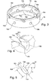
- an implantable capsule 10 here an autonomous capsule of cardiac stimulation, comprising a capsule body 12 and a helical screw anchor 14.
- the screw 14 is formed by a helically wound wire with a right screw thread and is mounted on a screw support 16 incorporating arrangements ensuring the irreversibility of the anchoring as will be seen in the following.
- the screw 14 is permanently secured to its support 16 for example by laser welding according to the distributed weld points.
- the assembly is then permanently secured to the body of the capsule 12 by a laser welding bead.
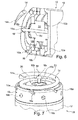
- the materials of the screw 14 and its support 16 may be different, for example a platinum / iridium 90/10 pair for the screw 14 and titanium for the support 16. It is indeed possible, as will be seen lower with reference to the illustrated embodiment Figures 8 and 9 , to implement a method of efficient assembly of these two elements even if they are made of heterogeneous materials.
- the different parts are for example made of biocompatible metal alloys such as stainless steel or a titanium alloy, preferably a biocompatible titanium alloy for the capsule body 12 and the support 16.
- the arrangements for the irreversibility of the binding comprise notches or recesses 16a formed in the support 16.
- the fixing assembly consisting of the parts 14, 16 has a diameter preferably equal to that of the body of the implant, typically from 6 to 7 mm, and a slightly lower axial length, typically between 4 and 6 mm.
- the screw 14 defines a free space occupied by another subset of the device, here a subset of stimulation electrodes.
- the fixation system is designed to fix the implant in a stable and durable manner over time by means of the helicoidal screw 14 forming a spring with progressive turns and ending with a tip able to perforate the endothelium and to penetrate the muscle tissues. , so as to press the cardiac wall on the generally annular end face of the support 16, substantially at the same position (in the axial direction) as the internal bearing surface of the electrode system.
- the screw support 16 has on said front face 16c a series of recesses 16a which perform the function of irreversibility once in contact with the endothelium.
- the fastening system is inchtmontable: under the action of the screw 14 which acts as a tension spring achieving an axial retention force, the cardiac wall is pressed against the face 16c of the screw support 16 and s' anchor locally in the recesses (here six in number, regularly distributed) by the aforementioned spring effect.
- the six recesses define as many sharp edges, but shallow, in their region (in the circumferential direction) opposite to the screwing direction of the propeller and then realize six points. anchoring punctual and distributed on the endothelium (mutual spacing of 60 ° in this example), which ensure irreversibility of screwing done to anchor the capsule.
- a stimulation subassembly is shown here constituted by two electrodes 18 and 20 held by an electrode support 22 which also supports at its periphery a ring 24 for the diffusion of a steroid product.
- the support 22 is positioned coaxially with the screw support 16, inside thereof, and fixed by gluing or any other suitable means on a wall 12a closing the internal space of the capsule body 12 at its distal end on the screw side. , the support being located precisely thanks to a circular shoulder 12b provided on the outer face of said wall.
- the central pellet stimulation electrode 18 is fixed (by crimping, gluing, etc.) in the center of the support 22 and electrically connected to the internal electronics of the capsule housed in the body 12, via a micro-crossing.
- the second electrode 20 has the form of a washer positioned and fixed, for example by gluing, on the outer face of the support 22 and is also connected via a micro-crossing to the internal electronics.
- the ring 24 is impregnated with a steroid product such as dexamethasone and is positioned under the electrode 20.
- a steroid product such as dexamethasone
- the electronics associated with the electrodes make it possible to implement, in the case of cardiac stimulation, detection and stimulation functions, the structure described guaranteeing a reliable and permanent contact between the electrodes 18, 20 and the tissues.
- the helical screw 14 here consists of a wire with a diameter of the order of 0.5 mm, with a winding diameter typically about 5 mm and preferably identical to that of the body 12 of the device.
- the screw comprises a plane base followed by two contiguous turns and a final turn extending for example about 1.5 turn with interspire space of the same order of magnitude as the diameter of the wire.
- the free end of the screw 14 is refined, in this case by two machining in mutually orthogonal planes, thus creating a piercing tip 14a but not sharp. The purpose of this tip is to easily cross the endothelium and then enter the heart muscle while creating a minimum of tissue damage.
- the screw 14 is here made of implantable and biocompatible 316L stainless steel or any other equivalent material, which delivers a stiffness of about 0.1 N / mm (linear stiffness of the spring, measured by traction or compression with the aid of a dynamometer on a stroke of 1 mm).
- the electrode 18 contributes to the fixing of the capsule while ensuring reliable and continuous contact with the compressed tissues by means of the axial force of the screw 14 towards the support 16.
- Such a configuration is particularly suitable for low energy stimulation, with a needle length of the order of 1.2 mm and a diameter of the order of 0.4 mm, ie an active surface of the order of 1 mm 2 .
- the support 16 of the screw 14 has as indicated a face or bearing edge 16c, preferably of slightly rounded profile, from which are formed, in the oblique direction, six recesses 16a for making six protruding edges 165 very localized and very punctual (see in particular Figures 4 and 5 ) ensuring the irreversibility of the screwing of the capsule made as described above.
- the localized perforation of the endothelium is obtained by the projecting ridges 165, the other edges which form the boundaries of the notch being voluntarily very rounded so as not to propagate or enlarge the piercing of the endothelium during the unscrewing efforts.
- the relative area occupied by the recesses of the support face 16c represents 20 to 40% of this surface, and more preferably around 30%, which makes it possible to limit the traumatic effect of the projecting ridges 165 by limiting the penetration of the tissues in the recesses 16a, while ensuring a good attachment of said ridges 165 in the endothelium, and therefore the effectiveness of the anti-wear function.
- the dimensions of the recesses may vary.
- their width l may be of the order of 0.3 to 0.8 mm
- their depth or length L may be between 0.5 and 1 mm
- their inclination ⁇ may be between 20 and 60 °, and preferably close to 45 °.
- the recesses 16a defining the projecting ridges 165 are made in a biodegradable part attached to the support 16.
- the material used to make this insert can be in particular a bioabsorbable biopolymer such as a polylactide (PLA ), a polyglycolide (PGA) or a polylactide-coglycolide (PLGA), or any other equivalent material, implantable and resorbable in the body.
- PLA polylactide
- PGA polyglycolide
- PLGA polylactide-coglycolide
- the pointed electrode 18 has an enlarged head 18a, preferably of conical shape, joining at its base by a retracting annular shoulder 18b, a narrower rod 18c.
- the shoulder 18b provides a surface that mechanically strengthens the stability of the capsule on the cardiac wall, participating in the retention of compressed tissue by the axial force of the screw 14.
- the shoulder 18b has an annular width of the order of 0.2 mm. This value may vary according to the needs and dimensions of the capsule, typically between 0.05 and 1 mm.
- the angle of the cone is meanwhile between about 30 and 60 °, and typically close to 50 °.
- the problem that solves this solution is to assemble a screw 14 stainless steel or other non-weldable material directly on the titanium case of the capsule.
- the support 16 has a configuration comprising a set of through orifices 16b, having a section corresponding approximately to that of the rods or tubes and for example circular, formed in the wall of the support 16, these orifices receiving rods or homologous tubes 14b formed at the periphery of the base of the screw 14, in corresponding angular locations.
- radial through orifices 16b are arranged in the support 16, which coincide with the portion of the contiguous turn screw.
- a rod or a tube 14b of the same material as the screw, or a laser weldable material to the material of the screw, is then inserted into each of these lateral holes.
- the bore of the tubes then opens on the turns of the screw.
- a laser shot through these holes then allows a direct weld tube / screw ensuring the requirements of a good laser welding, namely: i) compatibility of materials, ii) direct contact and iii) visual access for shooting and control quality.
- the screw 14 can be provided between the screw 14 and its support 16 a bayonet type mounting, the screw 14 then having at its base two rods or tubes such as 14b, preferably diametrically opposed, and the support 16 having in two diametrically opposed regions of the generally L-shaped notches 16d extending from the free face of the support 16 and allowing, before the laser welding, the mounting of the screw 14 by axial translation for the engagement of the rods or tubes in the notches, followed by a rotation to lock the rods or tubes to the bottom of the notches. There may then exist, in addition to these two notches, other notches 16d and / or other circular orifices 16b.
- step d) should not be understood in the narrow sense of a mechanical weld with fusion of the material of two separate parts, but an operation to collapse the material of the rod or tube inside the housing supporting the mechanical recoveries and strengthen the atraumatic function by removing the prominent forms.
- more orifices 16b or 16d are provided in number than the number of rods or tubes 14b of the screw 14. In this way, the orifices 16b or 16d remaining free make it possible to facilitate the diffusion of the steroid product delivered by the ring 24 radially. towards the heart wall.
- the notches 16d provided for such a bayonet type assembly are formed so as to participate in an anti-friction function as described above.
- the support 16 surrounds the base of the anchoring element, but alternately that the base of the anchoring element surrounds the support, in which case the skilled person will know how to do it. the necessary adaptations, particularly as regards the positioning of the rods or tubes 14b ensuring the attachment between the anchoring element and the support.
- the capsule can be placed by the practitioner according to the technique described in particular in the EP 2 394 695 A1 , and also extracted according to a known technique, the proximal portion 12 of the body of the capsule being arranged appropriately.
- the invention is not limited to the fixation of an autonomous stimulation capsule in a cardiac wall, but can be implemented for other implantable systems, whether autonomous or at the end of the probe, of the human body.
- the lengths of the helix and possibly the electrode can be easily adapted by the skilled person, without degrading the performance of fixation and irreversibility.
Abstract
L'invention concerne une capsule implantable (10), notamment une capsule autonome de stimulation cardiaque, comprenant un corps tubulaire (12) pourvu à son extrémité distale d'un élément d'ancrage à vis hélicoïdale (14) apte à pénétrer dans un tissu d'une paroi d'un organe d'un patient, le corps abritant un ensemble d'éléments fonctionnels de la capsule. Elle comprend dans une région annulaire (16c) entourant la base de la vis des aménagements en creux (16a) définissant un ensemble de pointes (165) affleurantes orientées dans une direction circonférentielle opposée à celle du vissage, pour éviter le dévissage de la capsule.The invention relates to an implantable capsule (10), in particular an autonomous capsule for cardiac stimulation, comprising a tubular body (12) provided at its distal end with a helical screw anchoring element (14) able to penetrate a tissue of a wall of an organ of a patient, the body housing a set of functional elements of the capsule. It comprises in an annular region (16c) surrounding the base of the screw recessed arrangements (16a) defining a set of tips (165) flush oriented in a circumferential direction opposite that of the screw, to prevent the unscrewing of the capsule.
Description
L'invention concerne les "dispositifs médicaux implantables actifs" tels que définis par la directive 90/385/CEE du 20 juin 1990 du Conseil des communautés européennes, plus précisément les implants permettant de surveiller en continu le rythme cardiaque et délivrer si nécessaire au coeur des impulsions électriques de stimulation, de resynchronisation et/ou de défibrillation en cas de trouble du rythme détecté par le dispositif. L'invention concerne notamment, mais de manière non limitative, ceux de ces dispositifs qui se présentent sous forme d'une capsule autonome destinée à être implantée dans une cavité cardiaque (ventricule ou oreillette, à droite ou à gauche). Ces capsules sont dépourvues de toute liaison mécanique à un dispositif principal implanté (tel qu'un boitier de générateur d'impulsions de stimulation) ou non implanté (périphérique externe tel que programmateur ou dispositif de monitoring pour le suivi à distance du patient), et sont dénommées pour cette raison "capsules leadless", pour les distinguer des électrodes ou des capteurs disposés à l'extrémité distale d'une sonde (lead) conventionnelle, qui est parcourue sur toute sa longueur par un ou plusieurs conducteurs reliant par voie galvanique l'électrode ou le capteur à un générateur connecté à une extrémité opposée, proximale, de la sonde.The invention relates to "active implantable medical devices" as defined by the Council of European Communities Directive 90/385 / EEC of 20 June 1990, more specifically implants for continuously monitoring the heart rate and delivering if necessary to the heart. electrical pacing, resynchronization and / or defibrillation pulses in case of rhythm disturbance detected by the device. The invention relates in particular, but without limitation, to those devices that are in the form of an autonomous capsule intended to be implanted in a heart chamber (ventricle or atrium, right or left). These capsules are devoid of any mechanical connection to an implanted main device (such as a stimulation pulse generator box) or not implanted (external device such as programmer or monitoring device for remote monitoring of the patient), and for this reason are called " leadless capsules ", to distinguish them from electrodes or sensors arranged at the distal end of a conventional lead , which is traversed over its entire length by one or more electrically connecting conductors. electrode or sensor to a generator connected to an opposite end, proximal, of the probe.
Le
On notera toutefois, comme on le comprendra à la lecture de la description, que le caractère autonome de la capsule n'est pas intrinsèquement une caractéristique nécessaire de l'invention, et que cette dernière peut être aussi bien appliquée à des capsules montées de façon permanente à l'extrémité distale d'une sonde.It will be appreciated, however, as will be understood from reading the description, that the autonomous nature of the capsule is not intrinsically a necessary feature of the invention, and that the latter can be applied equally to capsules mounted so permanent at the distal end of a probe.
Une capsule implantable comprend un corps abritant les principaux éléments du dispositif (circuits électroniques, source d'énergie, électrodes de stimulations, etc.) et une embase solidaire du corps et supportant rigidement un moyen de fixation à la paroi.An implantable capsule comprises a body housing the main elements of the device (electronic circuits, power source, stimulating electrodes, etc.) and a base integral with the body and rigidly supporting a means of attachment to the wall.
Dans le cas des sondes cardiaques, deux types de fixation sont reconnus et traditionnellement employés : la fixation dite à barbes est la plus ancienne et encore marginalement utilisée, mais les sondes basées sur une vis de fixation ont supplanté les sondes à barbes et représentent actuellement la majorité du marché. Elles permettent une fixation généralement robuste et efficace. La vis est une vis hélicoïdale saillante prolongeant axialement le corps de la capsule et destinée à pénétrer dans le tissu cardiaque par vissage au site d'implantation, de la même manière que pour les sondes à vis conventionnelles.In the case of cardiac probes, two types of fixation are recognized and traditionally used: the so-called beard fixation is the oldest and still marginally used, but the probes based on a fixation screw have supplanted the barb probes and currently represent the majority of the market. They allow a generally robust and effective fixation. The screw is a protruding helical screw axially extending the body of the capsule and intended to penetrate into the heart tissue by screwing to the implantation site, in the same way as for conventional screw probes.
Toutefois, la fixation de tels dispositifs reste un point critique dans la mesure où un détachement accidentel de la capsule amènerait cette dernière à être libérée dans la cavité cardiaque puis transportée par le sang dans le système veineux ou artériel. Le risque de complication pour le patient serait alors extrêmement élevé, ainsi que le risque de blessure du système cardiaque qui peut être engendré par l'extrémité du système de fixation ou toutes autres zones saillantes de l'implant comme par exemple une électrode pointue ou une arête saillante.However, the fixing of such devices remains a critical point insofar as accidental detachment of the capsule would cause the latter to be released into the heart chamber and then transported by the blood into the venous or arterial system. The risk of complication for the patient would be extremely high, as well as the risk of injury to the cardiac system that can be generated by the end of the fixation system or any other protruding areas of the implant such as a sharp electrode or a protruding edge.
Davantage qu'un dispositif à sonde, un dispositif autonome subit quant à lui les contraintes et les mouvements engendrés par la paroi cardiaque, car il ne bénéficie pas de l'effort axial de maintien de la part du corps de sonde.More than a probe device, an autonomous device undergoes the constraints and movements generated by the cardiac wall, because it does not benefit from the axial force of maintenance on the part of the probe body.
Pour remplir sa fonction d'ancrage permanent, le système de fixation doit donc comporter également une fonction d'irréversibilité, c'est-à-dire qu'il ne pourra être retiré de la paroi cardiaque que par l'intervention volontaire du médecin et suivant une procédure prédéfinie, mais en aucun cas par les mouvements ou vibrations répétés du coeur, ou par la modification du muscle cardiaque du faite de la maladie ou du vieillissement des tissus. Le
La présente invention vise à proposer un dispositif autonome implantable qui permette d'assurer une bonne opposition au dévissage, tout en ayant un effet traumatique beaucoup plus réduit.The present invention aims to provide an implantable independent device that allows to ensure good opposition to unscrewing, while having a much smaller traumatic effect.
Cet aspect est particulièrement critique, dans la mesure où les tissus avoisinants sont les premières cibles du processus de stimulation, et il est primordial de protéger ces tissus lors de la pose et pendant le fonctionnement du dispositif, afin d'assurer des seuils de stimulation bas et donc préserver la longévité du dispositif.This is particularly critical, as the surrounding tissues are the primary targets of the stimulation process, and it is essential to protect these tissues during installation and during operation of the device, to ensure low stimulation thresholds and thus preserve the longevity of the device.
Plus précisément, l'invention propose à cet effet une capsule implantable, notamment une capsule autonome de stimulation cardiaque, comprenant de manière en elle-même connue un corps tubulaire pourvu à son extrémité distale d'un élément d'ancrage à vis hélicoïdale apte à pénétrer dans un tissu d'une paroi d'un organe d'un patient, le corps abritant un ensemble d'éléments fonctionnels de la capsule. La capsule comprend en outre un ensemble de pointes orientées dans une direction circonférentielle opposée à celle du vissage.More specifically, the invention proposes for this purpose an implantable capsule, in particular an autonomous capsule for cardiac stimulation, comprising in a manner known per se a tubular body provided at its distal end with a helical screw anchoring element suitable for penetrate a tissue of a wall of an organ of a patient, the body housing a set of functional elements of the capsule. The capsule further comprises a set of tips oriented in a circumferential direction opposite that of the screwing.
De façon caractéristique de l'invention, la capsule comprend : une face d'appui annulaire formée dans une région annulaire entourant la base de la vis et située à l'extérieur de l'organe d'ancrage en direction radiale ; et, formés de manière affleurante dans ladite face d'appui annulaire, des aménagements en creux définissant ledit ensemble de pointes.In a characteristic manner of the invention, the capsule comprises: an annular bearing face formed in an annular region surrounding the base of the screw and located outside the anchoring member in the radial direction; and, formed flush in said annular bearing face, recessed arrangements defining said set of tips.
Selon diverses caractéristiques subsidiaires avantageuses :
- les aménagements en creux comprennent des évidements obliques formés à partir d'une face annulaire généralement continue du support de façon à former des pointes dirigées dans une direction circonférentielle opposée au vissage, avec notamment un angle d'inclinaison des évidements compris entre 40 et 60° par rapport à la surface de la face annulaire ;
- la proportion de la superficie de la face annulaire occupée par les évidements est comprise entre 20 et 40 %, et préférentiellement voisine de 30 % ;
- l'organe d'ancrage à vis est formé à partir d'un fil métallique élastique enroulé en hélice et se terminant en pointe, et apte à générer un effort de traction de ladite région annulaire en direction de ladite paroi, notamment avec un espacement entre les spires successives de l'hélice qui augmente entre une base de la vis et sa pointe ;
- la capsule comprend en outre une électrode en pointe en saillie à l'intérieur de l'organe à vis, cette électrode étant configurée en harpon. L'électrode peut notamment être une pièce de révolution centrée sur l'axe de rotation de la capsule lors du vissage, et/ou comprendre une tête conique à l'extrémité libre d'une tige plus étroite que la tête ;
- la capsule comprend en outre un anneau de diffusion de produit pharmaceutique disposé à l'intérieur de la région annulaire, les évidements étant aptes à favoriser la circulation du produit vers l'extérieur de ladite région ;
- la capsule comprend une pièce en matériau biodégradable dans laquelle sont réalisés les aménagements en creux définissant l'ensemble de pointes, le matériau biodégradable pouvant notamment être un biopolymère bioabsorbable du groupe formé par : les polylactides PLA, les polyglycolides PGA et les polylactides-co-glycolides PLGA.
- the hollow arrangements comprise oblique recesses formed from a generally continuous annular surface of the support so as to form points directed in a circumferential direction opposite to the screwing, with in particular an inclination angle of the recesses of between 40 and 60 ° with respect to the surface of the annular face;
- the proportion of the area of the annular face occupied by the recesses is between 20 and 40%, and preferably close to 30%;
- the anchor screw member is formed from an elastic wire wound helically and ending in a point, and adapted to generate a tensile force of said annular region towards said wall, in particular with a spacing between the successive turns of the helix which increases between a base of the screw and its tip;
- the capsule further comprises a pointed electrode projecting inside the screw member, this electrode being configured as a harpoon. The electrode may especially be a piece of revolution centered on the axis of rotation of the capsule during screwing, and / or comprise a conical head at the free end of a rod narrower than the head;
- the capsule further comprises a pharmaceutical diffusion ring disposed inside the annular region, the recesses being able to promote the circulation of the product towards the outside of said region;
- the capsule comprises a part made of biodegradable material in which the hollow arrangements defining the set of tips are made, the biodegradable material possibly being a bioabsorbable biopolymer of the group formed by: polylactides PLA, polyglycolides PGA and polylactides-co- PLGA glycolides.
On va maintenant décrire un exemple de mise en oeuvre de la présente invention, en référence aux dessins annexés où les mêmes références désignent d'une figure à l'autre des éléments identiques ou fonctionnellement semblables.
- La
Figure 1 est une vue d'ensemble en perspective d'une capsule implantable selon l'invention. - La
Figure 2 est une vue en perspective et en demi-coupe d'une région distale de la capsule de laFigure 1 . - La
Figure 3 est une vue en perspective d'un support de vis d'ancrage de la capsule desFigures 1 et 2 . - La
Figure 4 est une vue en perspective d'un détail du support de la Figure 3. - La
Figure 5 est une vue de profil du détail de laFigure 4 . - La
Figure 6 est une vue en perspective et en demi-coupe d'une région distale d'une capsule incorporant une variante de réalisation. - La
Figure 7 est une vue en perspective, selon une autre orientation, de cette même région distale. - La
Figure 8 est une vue en perspective d'un ensemble vis-support selon un autre aspect d'une capsule implantable, la vis étant visible en transparence. - La
Figure 9 est une vue en perspective de l'ensemble vis-support de laFigure 8 . - La
Figure 10 est une vue partielle en perspective d'une variante d'aménagement du support pour la fixation de la vis sur le support.
- The
Figure 1 is an overall perspective view of an implantable capsule according to the invention. - The
Figure 2 is a perspective and half-sectional view of a distal region of the capsule of theFigure 1 . - The
Figure 3 is a perspective view of an anchor screw support of the capsule ofFigures 1 and 2 . - The
Figure 4 is a perspective view of a detail of the support of Figure 3. - The
Figure 5 is a profile view of the detail of theFigure 4 . - The
Figure 6 is a perspective and half-sectional view of a distal region of a capsule incorporating an alternative embodiment. - The
Figure 7 is a perspective view, in another orientation, of this same distal region. - The
Figure 8 is a perspective view of a screw-support assembly according to another aspect of an implantable capsule, the screw being visible in transparency. - The
Figure 9 is a perspective view of the screw-support assembly of theFigure 8 . - The
Figure 10 is a partial perspective view of an alternative arrangement of the support for fixing the screw on the support.
On va maintenant décrire des exemples de réalisation d'une capsule implantable.Exemplary embodiments of an implantable capsule will now be described.
En référence tout d'abord à la
La vis 14 est formée par un fil enroulé en hélice à pas de vissage à droite et est montée sur un support de vis 16 intégrant des aménagements assurant l'irréversibilité de l'ancrage comme on va le voir dans la suite.The
La vis 14 est rendue définitivement solidaire de son support 16 par exemple par soudage laser selon les points de soudure répartis. L'ensemble est ensuite solidarisé définitivement au corps de la capsule 12 par un cordon de soudure laser.The
On notera que les matériaux de la vis 14 et de son support 16 peuvent être différents, par exemple un couple platine/iridium 90/10 pour la vis 14 et du titane pour le support 16. Il est en effet possible, comme on le verra plus bas en référence au mode de réalisation illustré
Les différentes pièces sont par exemple réalisées en alliages métalliques biocompatibles tels qu'un acier inoxydable ou un alliage de titane, de préférence un alliage de titane biocompatible pour le corps de capsule 12 et le support 16.The different parts are for example made of biocompatible metal alloys such as stainless steel or a titanium alloy, preferably a biocompatible titanium alloy for the
Les aménagements pour l'irréversibilité de la fixation comprennent des encoches ou évidements 16a formés dans le support 16.The arrangements for the irreversibility of the binding comprise notches or
L'ensemble de fixation constitué des pièces 14, 16 présente un diamètre de préférence égal à celui du corps de l'implant, typiquement de 6 à 7 mm, et une longueur axiale légèrement inférieure, typiquement entre 4 et 6 mm. La vis 14 délimite un espace libre occupé par un autre sous-ensemble du dispositif, ici un sous-ensemble d'électrodes de stimulation. Le système de fixation est conçu pour fixer l'implant de façon stable et durable dans le temps grâce à la vis hélicoïdale 14 formant un ressort à spires évolutives et se terminant par une pointe apte à perforer l'endothélium et à pénétrer dans les tissus musculaires, de façon à plaquer la paroi cardiaque sur la face frontale généralement annulaire du support 16, sensiblement à la même position (en direction axiale) que la surface d'appui interne du système d'électrode.The fixing assembly consisting of the
Plus en détail, le support de vis 16 présente sur ladite face frontale 16c une série d'évidements 16a qui réalisent la fonction d'irréversibilité une fois en contact avec l'endothélium. Dans cette position, le système de fixation est indémontable : sous l'action de la vis 14 qui agit comme un ressort de traction réalisant un effort de retenue axial, la paroi cardiaque est plaquée contre la face 16c du support de vis 16 et s'ancre localement dans les évidements (ici au nombre de six, régulièrement répartis) par l'effet ressort précité.In more detail, the
Comme on va le voir plus en détail dans la suite, les six évidements définissent autant d'arêtes vives, mais peu profondes, dans leur région (en direction circonférentielle) opposée au sens de vissage de l'hélice et réalisent alors six points d'ancrage ponctuels et répartis sur l'endothélium (espacement mutuel de 60° dans cet exemple), qui assurent une irréversibilité du vissage réalisé pour ancrer la capsule.As will be seen in more detail below, the six recesses define as many sharp edges, but shallow, in their region (in the circumferential direction) opposite to the screwing direction of the propeller and then realize six points. anchoring punctual and distributed on the endothelium (mutual spacing of 60 ° in this example), which ensure irreversibility of screwing done to anchor the capsule.
Maintenant plus en détail et en référence à la
Le support 22 est positionné coaxialement au support de vis 16, à l'intérieur de celui-ci, et fixé par collage ou tout autre moyen approprié sur une paroi 12a fermant l'espace intérieur du corps de capsule 12 à son extrémité distale côté vis, le support étant localisé précisément grâce à un épaulement circulaire 12b prévu sur la face extérieure de ladite paroi. L'électrode de stimulation centrale en pointe 18 est fixée (par sertissage, collage, etc.) au centre du support 22 et connectée électriquement à l'électronique interne de la capsule logée dans le corps 12, par l'intermédiaire d'une micro-traversée. La deuxième électrode 20 présente ici la forme d'une rondelle positionnée et fixée, par exemple par collage, sur la face externe du support 22 et est connectée également par le biais d'une micro-traversée à l'électronique interne.The
L'anneau 24 est imprégné d'un produit stéroïde tel que la dexaméthasone et est positionné sous l'électrode 20. Le produit stéroïde permet de réduire l'inflammation tissulaire durant les premières semaines qui suivent l'implantation.The
L'électronique associée aux électrodes permet de mettre en oeuvre, dans le cas d'une stimulation cardiaque, des fonctions de détection et de stimulation, la structure décrite garantissant un contact fiable et permanent entre les électrodes 18, 20 et les tissus.The electronics associated with the electrodes make it possible to implement, in the case of cardiac stimulation, detection and stimulation functions, the structure described guaranteeing a reliable and permanent contact between the
La vis en hélice 14 est ici constituée d'un fil métallique d'un diamètre de l'ordre de 0,5 mm, avec un diamètre d'enroulement typiquement 5 mm environ et de préférence identique à celui du corps 12 du dispositif. La vis comprend une base plane suivie par deux spires jointives et une spire finale s'étendant par exemple sur environ 1,5 tour avec un espace interspire du même ordre de grandeur que le diamètre du fil. L'extrémité libre de la vis 14 est affinée, dans le cas d'espèce par deux usinages dans des plans mutuellement orthogonaux, créant ainsi une pointe 14a perforante mais non tranchante. Le but de cette pointe est de permettre de traverser facilement l'endothélium puis de pénétrer dans le muscle cardiaque tout en créant un minimum de lésions tissulaires. La vis 14 est ici réalisée en acier inoxydable 316L implantable et biocompatible ou toute autre matière équivalente, qui délivre une raideur d'environ 0,1 N/mm (raideur linéaire du ressort, mesurée par traction ou compression à l'aide d'un dynamomètre sur une course de 1 mm).The
Ceci donne à la vis une souplesse axiale qui lui confère un effet ressort, opérant un effort de traction assurant un contact ferme entre le support 16 et la paroi cardiaque. Ainsi lors de la pénétration de la vis 14 dans le muscle, la vis se déforme axialement jusqu'au contact du bord libre 16c du support 16 avec l'endothélium. L'effet ressort de la vis va alors comprimer axialement l'endothélium et le muscle entre les spires et créer un effet de coincement. De plus, la proximité immédiate des spires et leur effet de traction sur l'endothélium forcent l'entrée de ce dernier dans les encoches d'antidévissage. Au cours de ce mouvement, l'électrode de stimulation en pointe 18 perfore l'endothélium et vient ainsi en contact avec les cellules excitables de la paroi cardiaque.This gives the screw an axial flexibility that gives it a spring effect, operating a tensile force ensuring a firm contact between the
D'autres configurations de spires sont bien entendu possibles, mais il est avantageux de prévoir un espacement entre spires qui augmente entre la base de la vis (où comme on l'a vu l'espacement peut être nul) et la pointe 14a de la vis. Ceci permet de favoriser l'effort de traction axial appliquant le support 16 contre la paroi cardiaque.Other configurations of turns are of course possible, but it is advantageous to provide a spacing between turns which increases between the base of the screw (where as we saw the spacing may be zero) and the
On comprend par ailleurs que l'électrode 18 contribue à la fixation de la capsule tout en assurant contact fiable et continu avec les tissus comprimés grâce à l'effort axial de la vis 14 en direction du support 16.It will further be understood that the
Une telle configuration est particulièrement adaptée pour une stimulation basse énergie, avec une longueur d'aiguille de l'ordre de 1,2 mm et un diamètre de l'ordre de 0,4 mm, soit une surface active de l'ordre de 1 mm2.Such a configuration is particularly suitable for low energy stimulation, with a needle length of the order of 1.2 mm and a diameter of the order of 0.4 mm, ie an active surface of the order of 1 mm 2 .
En référence tout particulièrement aux
Les dimensions des évidements peuvent varier. Par exemple et en référence particulièrement à la
Dans une variante de mise en oeuvre avantageuse, les évidements 16a définissant les arêtes saillantes 165 sont réalisés dans une pièce biodégradable rapportée sur le support 16. La matière utilisée pour réaliser cette pièce rapportée peut être notamment un biopolymère bioabsorbable tel qu'un polylactide (PLA), un polyglycolide (PGA) ou un polylactide-coglycolide (PLGA), ou toute autre matière équivalente, implantable et résorbable dans l'organisme. La fonction antidévissage sera alors assurée pendant une période prédéfinie, par exemple de 3 à 12 mois, pendant laquelle la fibrose recouvrira progressivement l'embase de la capsule. Puis, à long terme, il deviendra plus facile de retirer la capsule une fois la fonction antidévissage disparue.In an advantageous embodiment, the
En référence maintenant aux
Dans le présent exemple, l'épaulement 18b présente une largeur annulaire de l'ordre de 0,2 mm. Cette valeur peut varier selon les besoins et les dimensions de la capsule, typiquement entre 0.05 et 1 mm.In the present example, the
L'angle du cône est quant à lui compris entre environ 30 et 60°, et typiquement voisin de 50°.The angle of the cone is meanwhile between about 30 and 60 °, and typically close to 50 °.
On va maintenant décrite une solution d'assemblage permanent de la vis 14 sur son support 16, cette solution pouvant être mise en oeuvre indépendamment des caractéristiques d'antidévissage et d'accrochage à la paroi cardiaque telles que détaillées dans ce qui précède.A permanent assembly solution of the
Le problème que résout cette solution est de pouvoir assembler une vis 14 en acier inox ou autre matériau non soudable directement sur le boitier en titane de la capsule.The problem that solves this solution is to assemble a
Ainsi, en référence aux
Cette soudure effectuée, la vis se trouve bloquée en translation et rotation dans son support, par ancrage mécanique et sans soudure laser directe, ce qui laisse une grande liberté dans la combinaison de matériaux support/vis. Les autres avantages sensibles de cette solution sont le faible encombrement et la très faible complexité des usinages à réaliser.This welding carried out, the screw is locked in translation and rotation in its support, by mechanical anchoring and without direct laser welding, which leaves a great freedom in the combination of materials support / screw. The other significant advantages of this solution are the small size and the very low complexity of the machining to be performed.
Selon une variante de réalisation illustrée sur la
Dans le premier cas décrit plus haut, le procédé d'assemblage de la capsule comprend de préférence les étapes suivantes :
- a) on fixe le
support 16 au corps, par soudage, - b) on engage la base de l'élément 14 à l'intérieur dudit support,
- c) on engage dans les
orifices 16b les tigesou tubes 14b, - d) on soude les tiges ou tubes sur la base de l'élément 14, par tir laser via l'intérieur du support, et
- e) on soude les tiges ou tubes dans leurs orifices respectifs, par tir laser extérieurement au support.
- a) the
support 16 is fixed to the body by welding, - b) the base of the
element 14 is engaged inside said support, - c) the rods or
tubes 14b are engaged in theorifices 16b, - d) the rods or tubes are welded to the base of the
element 14 by laser firing via the interior of the support, and - e) the rods or tubes are welded in their respective orifices, by laser fire externally to the support.
On notera que le "soudage" de l'étape d) ne doit pas être entendu au sens étroit d'une soudure mécanique avec fusion de la matière de deux pièces distinctes, mais d'une opération destinée à effondrer la matière de la tige ou du tube à l'intérieur du logement supportant les reprises mécaniques et renforcer la fonction atraumatique par suppression des formes saillantes.Note that the "welding" of step d) should not be understood in the narrow sense of a mechanical weld with fusion of the material of two separate parts, but an operation to collapse the material of the rod or tube inside the housing supporting the mechanical recoveries and strengthen the atraumatic function by removing the prominent forms.
Dans le cas de la variante de la
- a) on fixe le
support 16 pourvu des encoches 16d au corps, par soudage, - b) on soude les tiges ou tubes sur la base de l'élément 14, par tir laser,
- c) on pré-assemble l'élément d'ancrage par sa base dans le support, par montage de type baïonnette mettant en jeu lesdits tiges ou tubes et lesdites encoches, et
- d) on soude les tiges ou tubes dans les encoches, par tir laser extérieurement au support.
- a) the
support 16 provided with thenotches 16d is fixed to the body by welding, - b) the rods or tubes are welded to the base of the
element 14, by laser firing, - c) the anchoring element is pre-assembled by its base in the support, by bayonet type assembly involving said rods or tubes and said notches, and
- d) the rods or tubes are welded into the notches by laser fire externally to the support.
Avantageusement, on prévoit des orifices 16b ou 16d en nombre supérieur au nombre de tiges ou tubes 14b de la vis 14. De la sorte, les orifices 16b ou 16d restant libres permettent de faciliter la diffusion du produit stéroïde délivré par l'anneau 24 radialement en direction de la paroi cardiaque.Advantageously,
Selon une autre variante, on peut prévoir que les encoches 16d prévues pour un tel montage de type baïonnette soient formées de façon à participer à une fonction d'antidévissage comme décrit précédemment.According to another variant, it can be provided that the
Les différents éléments et parties décrits ci-dessus peuvent être réalisés par usinage ou autre mise en forme selon des techniques conventionnelles.The various elements and parts described above can be made by machining or other shaping according to conventional techniques.
Par ailleurs, on peut prévoir comme décrit plus haut que le support 16 entoure la base de l'élément d'ancrage, mais alternativement que la base de l'élément d'ancrage entoure le support, auquel cas l'homme du métier saura faire les adaptations nécessaires, notamment quant au positionnement des tiges ou tubes 14b assurant la fixation entre l'élément d'ancrage et le support.Moreover, it can be provided as described above that the
La capsule peut être posée par le praticien selon la technique décrite notamment dans le
L'invention ne se limite nullement à la fixation d'une capsule de stimulation autonome dans une paroi cardiaque, mais peut être mise en oeuvre pour d'autres systèmes implantables, qu'ils soient autonomes ou en bout de sonde, du corps humain. En fonction de la nature de la paroi de fixation visée, les longueurs d'hélice et le cas échéant d'électrode peuvent seront facilement adaptées par l'homme du métier, sans pour autant dégrader les performances de fixation et d'irréversibilité.The invention is not limited to the fixation of an autonomous stimulation capsule in a cardiac wall, but can be implemented for other implantable systems, whether autonomous or at the end of the probe, of the human body. Depending on the nature of the target attachment wall, the lengths of the helix and possibly the electrode can be easily adapted by the skilled person, without degrading the performance of fixation and irreversibility.
Claims (12)
caractérisée en ce qu'elle comprend :
characterized in that it comprises:
Applications Claiming Priority (1)
| Application Number | Priority Date | Filing Date | Title |
|---|---|---|---|
| FR1455896 | 2014-06-25 |
Publications (2)
| Publication Number | Publication Date |
|---|---|
| EP2959936A1 true EP2959936A1 (en) | 2015-12-30 |
| EP2959936B1 EP2959936B1 (en) | 2021-03-31 |
Family
ID=51862406
Family Applications (1)
| Application Number | Title | Priority Date | Filing Date |
|---|---|---|---|
| EP15167098.1A Active EP2959936B1 (en) | 2014-06-25 | 2015-05-11 | Implantable capsule with attachment by screwing, in particular an autonomous cardiac stimulation capsule |
Country Status (2)
| Country | Link |
|---|---|
| US (1) | US9555236B2 (en) |
| EP (1) | EP2959936B1 (en) |
Families Citing this family (16)
| Publication number | Priority date | Publication date | Assignee | Title |
|---|---|---|---|---|
| CN109982738B (en) | 2016-11-21 | 2021-06-22 | 心脏起搏器股份公司 | Delivery device and wall attachment sensing |
| US11198013B2 (en) | 2016-11-21 | 2021-12-14 | Cardiac Pacemakers, Inc. | Catheter and leadless cardiac devices including electrical pathway barrier |
| US10806931B2 (en) | 2016-12-27 | 2020-10-20 | Cardiac Pacemakers, Inc. | Delivery devices and methods for leadless cardiac devices |
| US10894162B2 (en) | 2016-12-27 | 2021-01-19 | Cardiac Pacemakers, Inc. | Delivery devices and methods for leadless cardiac devices |
| EP3562547B1 (en) | 2016-12-27 | 2020-11-18 | Cardiac Pacemakers, Inc. | Leadless delivery catheter with conductive pathway |
| US10485981B2 (en) | 2016-12-27 | 2019-11-26 | Cardiac Pacemakers, Inc. | Fixation methods for leadless cardiac devices |
| CN110225779B (en) | 2017-01-26 | 2023-04-04 | 心脏起搏器股份公司 | Delivery device for leadless cardiac devices |
| US11229798B2 (en) | 2017-03-10 | 2022-01-25 | Cardiac Pacemakers, Inc. | Fixation for leadless cardiac devices |
| US10737092B2 (en) | 2017-03-30 | 2020-08-11 | Cardiac Pacemakers, Inc. | Delivery devices and methods for leadless cardiac devices |
| US11577085B2 (en) | 2017-08-03 | 2023-02-14 | Cardiac Pacemakers, Inc. | Delivery devices and methods for leadless cardiac devices |
| US11446510B2 (en) | 2019-03-29 | 2022-09-20 | Cardiac Pacemakers, Inc. | Systems and methods for treating cardiac arrhythmias |
| US11833349B2 (en) | 2019-03-29 | 2023-12-05 | Cardiac Pacemakers, Inc. | Systems and methods for treating cardiac arrhythmias |
| WO2021050685A1 (en) | 2019-09-11 | 2021-03-18 | Cardiac Pacemakers, Inc. | Tools and systems for implanting and/or retrieving a leadless cardiac pacing device with helix fixation |
| CN114364431A (en) | 2019-09-11 | 2022-04-15 | 心脏起搏器股份公司 | Tool and system for implanting and/or retrieving a leadless cardiac pacing device having a helical fixation member |
| US11684789B2 (en) * | 2020-01-27 | 2023-06-27 | Pacesetter, Inc. | Biostimulator header assembly having ceramic helix mount |
| WO2022152470A1 (en) * | 2021-01-15 | 2022-07-21 | Biotronik Se & Co. Kg | A medical implant anchoring element with improved characteristics for implantation and retention |
Citations (4)
| Publication number | Priority date | Publication date | Assignee | Title |
|---|---|---|---|---|
| WO2001026706A2 (en) * | 1999-10-13 | 2001-04-19 | Biocardia, Inc. | Drug delivery catheters that attach to tissue and methods for their use |
| US20080109042A1 (en) * | 2006-11-08 | 2008-05-08 | Cardiac Pacemakers, Inc. | Cardiac lead with a retractable helix |
| EP2394695A1 (en) | 2010-06-14 | 2011-12-14 | Sorin CRM SAS | Standalone intracardiac capsule and implantation accessory |
| WO2012051235A1 (en) | 2010-10-13 | 2012-04-19 | Nanostim, Inc. | Leadless cardiac pacemaker with anti-unscrewing feature |
Family Cites Families (4)
| Publication number | Priority date | Publication date | Assignee | Title |
|---|---|---|---|---|
| US5456708A (en) * | 1993-10-28 | 1995-10-10 | Pacesetter, Inc. | Rotatable pin, screw-in pacing and sensing lead having improved tip and fluidic seal |
| EP1687043A2 (en) * | 2003-11-20 | 2006-08-09 | Angiotech International Ag | Electrical devices and anti-scarring agents |
| EP2537555B1 (en) * | 2011-06-24 | 2013-05-01 | Sorin CRM SAS | Leadless autonomous intracardiac implant with disengageable attachment element |
| US20130123872A1 (en) * | 2011-11-03 | 2013-05-16 | Pacesetter, Inc. | Leadless implantable medical device with dual chamber sensing functionality |
-
2015
- 2015-05-11 EP EP15167098.1A patent/EP2959936B1/en active Active
- 2015-06-19 US US14/744,916 patent/US9555236B2/en active Active
Patent Citations (4)
| Publication number | Priority date | Publication date | Assignee | Title |
|---|---|---|---|---|
| WO2001026706A2 (en) * | 1999-10-13 | 2001-04-19 | Biocardia, Inc. | Drug delivery catheters that attach to tissue and methods for their use |
| US20080109042A1 (en) * | 2006-11-08 | 2008-05-08 | Cardiac Pacemakers, Inc. | Cardiac lead with a retractable helix |
| EP2394695A1 (en) | 2010-06-14 | 2011-12-14 | Sorin CRM SAS | Standalone intracardiac capsule and implantation accessory |
| WO2012051235A1 (en) | 2010-10-13 | 2012-04-19 | Nanostim, Inc. | Leadless cardiac pacemaker with anti-unscrewing feature |
Also Published As
| Publication number | Publication date |
|---|---|
| US20160008594A1 (en) | 2016-01-14 |
| US9555236B2 (en) | 2017-01-31 |
| EP2959936B1 (en) | 2021-03-31 |
Similar Documents
| Publication | Publication Date | Title |
|---|---|---|
| EP2959940B1 (en) | Implantable capsule with attachment by screwing, in particular an autonomous cardiac stimulation capsule | |
| EP2959936B1 (en) | Implantable capsule with attachment by screwing, in particular an autonomous cardiac stimulation capsule | |
| EP3173126B1 (en) | Implantable capsule, in particular an autonomous cardiac stimulation capsule, and its method of assembly | |
| EP2881141B1 (en) | Implantable intracardiac capsule on a thin wall, in particular the septal wall | |
| EP2929910B1 (en) | Intracardiac capsule and accessory for explanting same | |
| EP0207438B1 (en) | Stylet for an implantable electrode | |
| EP3069754B1 (en) | In situ implantation accessory for self-contained intracardiac capsule | |
| EP2384784B1 (en) | Assembly for endocavitary stimulation/defibrillation of the left ventricle | |
| FR2511251A1 (en) | POROUS ELECTRODE POINT FOR CARDIAC STIMULATOR AND METHOD OF MANUFACTURE | |
| EP2719424B1 (en) | Intraseptal probe for left ventricular stimulation | |
| FR2786701A1 (en) | Electrical heart stimulator or defibrillator has conductor, electrode(s) and atrium branch | |
| US8126557B2 (en) | Lead connector pin and body assembly and method of manufacture | |
| EP3681589B1 (en) | Implantable autonomous heart capsule with orientable head and torque limiter | |
| CN109498995B (en) | Attachment device for implantable cardiac device | |
| FR3082434A1 (en) | AUTONOMOUS HEART IMPLANT TYPE "CAPSULE LEADLESS", COMPRISING AN ENERGY RECOVERY WITH A PIEZOELECTRIC BLADE | |
| FR2607013A1 (en) | CARDIAC STIMULATION PROBE | |
| EP2818202A1 (en) | Coupling system between a medical device and an accessory for in situ implantation thereof | |
| EP2574368B1 (en) | Multizone epicardial stimulation probe | |
| EP3058983A1 (en) | Detection/stimulation microprobe, in particular for multipoint neuromodulation of the central nervous system | |
| EP1557194B1 (en) | Single-piece defibrillation sonde | |
| EP4205799B1 (en) | Implantable medical device with non-traumatic helical anchoring screw | |
| EP1036572B1 (en) | Cardiac lead implantable in the coronary veins for stimulating the left atria | |
| FR3087344A1 (en) | COUPLING SYSTEM BETWEEN AN AUTONOMOUS HEART CAPSULE AND ITS IMPLANTATION TOOL | |
| FR2962641A1 (en) | IMPLANT DEVICE AND INSTALLATION TOOL | |
| FR2932389A1 (en) | Distal head for e.g. bipolar stimulation probe, of cardiac stimulation device, has moving units comprising movable element movable with respect to hollow body, and fixed element serving as stop to movable element |
Legal Events
| Date | Code | Title | Description |
|---|---|---|---|
| PUAI | Public reference made under article 153(3) epc to a published international application that has entered the european phase |
Free format text: ORIGINAL CODE: 0009012 |
|
| AK | Designated contracting states |
Kind code of ref document: A1 Designated state(s): AL AT BE BG CH CY CZ DE DK EE ES FI FR GB GR HR HU IE IS IT LI LT LU LV MC MK MT NL NO PL PT RO RS SE SI SK SM TR |
|
| AX | Request for extension of the european patent |
Extension state: BA ME |
|
| 17P | Request for examination filed |
Effective date: 20160523 |
|
| RBV | Designated contracting states (corrected) |
Designated state(s): AL AT BE BG CH CY CZ DE DK EE ES FI FR GB GR HR HU IE IS IT LI LT LU LV MC MK MT NL NO PL PT RO RS SE SI SK SM TR |
|
| STAA | Information on the status of an ep patent application or granted ep patent |
Free format text: STATUS: EXAMINATION IS IN PROGRESS |
|
| 17Q | First examination report despatched |
Effective date: 20191111 |
|
| GRAP | Despatch of communication of intention to grant a patent |
Free format text: ORIGINAL CODE: EPIDOSNIGR1 |
|
| STAA | Information on the status of an ep patent application or granted ep patent |
Free format text: STATUS: GRANT OF PATENT IS INTENDED |
|
| INTG | Intention to grant announced |
Effective date: 20201023 |
|
| GRAS | Grant fee paid |
Free format text: ORIGINAL CODE: EPIDOSNIGR3 |
|
| GRAA | (expected) grant |
Free format text: ORIGINAL CODE: 0009210 |
|
| STAA | Information on the status of an ep patent application or granted ep patent |
Free format text: STATUS: THE PATENT HAS BEEN GRANTED |
|
| AK | Designated contracting states |
Kind code of ref document: B1 Designated state(s): AL AT BE BG CH CY CZ DE DK EE ES FI FR GB GR HR HU IE IS IT LI LT LU LV MC MK MT NL NO PL PT RO RS SE SI SK SM TR |
|
| REG | Reference to a national code |
Ref country code: GB Ref legal event code: FG4D Free format text: NOT ENGLISH Ref country code: CH Ref legal event code: EP |
|
| REG | Reference to a national code |
Ref country code: AT Ref legal event code: REF Ref document number: 1376250 Country of ref document: AT Kind code of ref document: T Effective date: 20210415 Ref country code: DE Ref legal event code: R096 Ref document number: 602015067387 Country of ref document: DE |
|
| REG | Reference to a national code |
Ref country code: IE Ref legal event code: FG4D Free format text: LANGUAGE OF EP DOCUMENT: FRENCH |
|
| REG | Reference to a national code |
Ref country code: LT Ref legal event code: MG9D |
|
| PG25 | Lapsed in a contracting state [announced via postgrant information from national office to epo] |
Ref country code: FI Free format text: LAPSE BECAUSE OF FAILURE TO SUBMIT A TRANSLATION OF THE DESCRIPTION OR TO PAY THE FEE WITHIN THE PRESCRIBED TIME-LIMIT Effective date: 20210331 Ref country code: HR Free format text: LAPSE BECAUSE OF FAILURE TO SUBMIT A TRANSLATION OF THE DESCRIPTION OR TO PAY THE FEE WITHIN THE PRESCRIBED TIME-LIMIT Effective date: 20210331 Ref country code: BG Free format text: LAPSE BECAUSE OF FAILURE TO SUBMIT A TRANSLATION OF THE DESCRIPTION OR TO PAY THE FEE WITHIN THE PRESCRIBED TIME-LIMIT Effective date: 20210630 Ref country code: NO Free format text: LAPSE BECAUSE OF FAILURE TO SUBMIT A TRANSLATION OF THE DESCRIPTION OR TO PAY THE FEE WITHIN THE PRESCRIBED TIME-LIMIT Effective date: 20210630 |
|
| PG25 | Lapsed in a contracting state [announced via postgrant information from national office to epo] |
Ref country code: RS Free format text: LAPSE BECAUSE OF FAILURE TO SUBMIT A TRANSLATION OF THE DESCRIPTION OR TO PAY THE FEE WITHIN THE PRESCRIBED TIME-LIMIT Effective date: 20210331 Ref country code: LV Free format text: LAPSE BECAUSE OF FAILURE TO SUBMIT A TRANSLATION OF THE DESCRIPTION OR TO PAY THE FEE WITHIN THE PRESCRIBED TIME-LIMIT Effective date: 20210331 Ref country code: SE Free format text: LAPSE BECAUSE OF FAILURE TO SUBMIT A TRANSLATION OF THE DESCRIPTION OR TO PAY THE FEE WITHIN THE PRESCRIBED TIME-LIMIT Effective date: 20210331 |
|
| REG | Reference to a national code |
Ref country code: NL Ref legal event code: MP Effective date: 20210331 |
|
| REG | Reference to a national code |
Ref country code: AT Ref legal event code: MK05 Ref document number: 1376250 Country of ref document: AT Kind code of ref document: T Effective date: 20210331 |
|
| PG25 | Lapsed in a contracting state [announced via postgrant information from national office to epo] |
Ref country code: NL Free format text: LAPSE BECAUSE OF FAILURE TO SUBMIT A TRANSLATION OF THE DESCRIPTION OR TO PAY THE FEE WITHIN THE PRESCRIBED TIME-LIMIT Effective date: 20210331 Ref country code: LT Free format text: LAPSE BECAUSE OF FAILURE TO SUBMIT A TRANSLATION OF THE DESCRIPTION OR TO PAY THE FEE WITHIN THE PRESCRIBED TIME-LIMIT Effective date: 20210331 Ref country code: CZ Free format text: LAPSE BECAUSE OF FAILURE TO SUBMIT A TRANSLATION OF THE DESCRIPTION OR TO PAY THE FEE WITHIN THE PRESCRIBED TIME-LIMIT Effective date: 20210331 Ref country code: EE Free format text: LAPSE BECAUSE OF FAILURE TO SUBMIT A TRANSLATION OF THE DESCRIPTION OR TO PAY THE FEE WITHIN THE PRESCRIBED TIME-LIMIT Effective date: 20210331 Ref country code: AT Free format text: LAPSE BECAUSE OF FAILURE TO SUBMIT A TRANSLATION OF THE DESCRIPTION OR TO PAY THE FEE WITHIN THE PRESCRIBED TIME-LIMIT Effective date: 20210331 Ref country code: SM Free format text: LAPSE BECAUSE OF FAILURE TO SUBMIT A TRANSLATION OF THE DESCRIPTION OR TO PAY THE FEE WITHIN THE PRESCRIBED TIME-LIMIT Effective date: 20210331 |
|
| PG25 | Lapsed in a contracting state [announced via postgrant information from national office to epo] |
Ref country code: ES Free format text: LAPSE BECAUSE OF FAILURE TO SUBMIT A TRANSLATION OF THE DESCRIPTION OR TO PAY THE FEE WITHIN THE PRESCRIBED TIME-LIMIT Effective date: 20210331 Ref country code: PL Free format text: LAPSE BECAUSE OF FAILURE TO SUBMIT A TRANSLATION OF THE DESCRIPTION OR TO PAY THE FEE WITHIN THE PRESCRIBED TIME-LIMIT Effective date: 20210331 Ref country code: PT Free format text: LAPSE BECAUSE OF FAILURE TO SUBMIT A TRANSLATION OF THE DESCRIPTION OR TO PAY THE FEE WITHIN THE PRESCRIBED TIME-LIMIT Effective date: 20210802 Ref country code: SK Free format text: LAPSE BECAUSE OF FAILURE TO SUBMIT A TRANSLATION OF THE DESCRIPTION OR TO PAY THE FEE WITHIN THE PRESCRIBED TIME-LIMIT Effective date: 20210331 Ref country code: RO Free format text: LAPSE BECAUSE OF FAILURE TO SUBMIT A TRANSLATION OF THE DESCRIPTION OR TO PAY THE FEE WITHIN THE PRESCRIBED TIME-LIMIT Effective date: 20210331 Ref country code: IS Free format text: LAPSE BECAUSE OF FAILURE TO SUBMIT A TRANSLATION OF THE DESCRIPTION OR TO PAY THE FEE WITHIN THE PRESCRIBED TIME-LIMIT Effective date: 20210731 |
|
| REG | Reference to a national code |
Ref country code: CH Ref legal event code: PL |
|
| REG | Reference to a national code |
Ref country code: DE Ref legal event code: R097 Ref document number: 602015067387 Country of ref document: DE |
|
| PG25 | Lapsed in a contracting state [announced via postgrant information from national office to epo] |
Ref country code: MC Free format text: LAPSE BECAUSE OF FAILURE TO SUBMIT A TRANSLATION OF THE DESCRIPTION OR TO PAY THE FEE WITHIN THE PRESCRIBED TIME-LIMIT Effective date: 20210331 Ref country code: LU Free format text: LAPSE BECAUSE OF NON-PAYMENT OF DUE FEES Effective date: 20210511 Ref country code: LI Free format text: LAPSE BECAUSE OF NON-PAYMENT OF DUE FEES Effective date: 20210531 Ref country code: CH Free format text: LAPSE BECAUSE OF NON-PAYMENT OF DUE FEES Effective date: 20210531 Ref country code: AL Free format text: LAPSE BECAUSE OF FAILURE TO SUBMIT A TRANSLATION OF THE DESCRIPTION OR TO PAY THE FEE WITHIN THE PRESCRIBED TIME-LIMIT Effective date: 20210331 Ref country code: DK Free format text: LAPSE BECAUSE OF FAILURE TO SUBMIT A TRANSLATION OF THE DESCRIPTION OR TO PAY THE FEE WITHIN THE PRESCRIBED TIME-LIMIT Effective date: 20210331 |
|
| PLBE | No opposition filed within time limit |
Free format text: ORIGINAL CODE: 0009261 |
|
| STAA | Information on the status of an ep patent application or granted ep patent |
Free format text: STATUS: NO OPPOSITION FILED WITHIN TIME LIMIT |
|
| REG | Reference to a national code |
Ref country code: BE Ref legal event code: MM Effective date: 20210531 |
|
| 26N | No opposition filed |
Effective date: 20220104 |
|
| PG25 | Lapsed in a contracting state [announced via postgrant information from national office to epo] |
Ref country code: IE Free format text: LAPSE BECAUSE OF NON-PAYMENT OF DUE FEES Effective date: 20210511 |
|
| REG | Reference to a national code |
Ref country code: DE Ref legal event code: R082 Ref document number: 602015067387 Country of ref document: DE Representative=s name: PAGE, WHITE & FARRER GERMANY LLP, DE |
|
| PG25 | Lapsed in a contracting state [announced via postgrant information from national office to epo] |
Ref country code: IS Free format text: LAPSE BECAUSE OF FAILURE TO SUBMIT A TRANSLATION OF THE DESCRIPTION OR TO PAY THE FEE WITHIN THE PRESCRIBED TIME-LIMIT Effective date: 20210731 |
|
| PG25 | Lapsed in a contracting state [announced via postgrant information from national office to epo] |
Ref country code: BE Free format text: LAPSE BECAUSE OF NON-PAYMENT OF DUE FEES Effective date: 20210531 |
|
| PG25 | Lapsed in a contracting state [announced via postgrant information from national office to epo] |
Ref country code: HU Free format text: LAPSE BECAUSE OF FAILURE TO SUBMIT A TRANSLATION OF THE DESCRIPTION OR TO PAY THE FEE WITHIN THE PRESCRIBED TIME-LIMIT; INVALID AB INITIO Effective date: 20150511 |
|
| PG25 | Lapsed in a contracting state [announced via postgrant information from national office to epo] |
Ref country code: CY Free format text: LAPSE BECAUSE OF FAILURE TO SUBMIT A TRANSLATION OF THE DESCRIPTION OR TO PAY THE FEE WITHIN THE PRESCRIBED TIME-LIMIT Effective date: 20210331 |
|
| PG25 | Lapsed in a contracting state [announced via postgrant information from national office to epo] |
Ref country code: GR Free format text: LAPSE BECAUSE OF FAILURE TO SUBMIT A TRANSLATION OF THE DESCRIPTION OR TO PAY THE FEE WITHIN THE PRESCRIBED TIME-LIMIT Effective date: 20210331 |
|
| PGFP | Annual fee paid to national office [announced via postgrant information from national office to epo] |
Ref country code: IT Payment date: 20230523 Year of fee payment: 9 Ref country code: FR Payment date: 20230523 Year of fee payment: 9 Ref country code: DE Payment date: 20230510 Year of fee payment: 9 |
|
| P01 | Opt-out of the competence of the unified patent court (upc) registered |
Effective date: 20230714 |
|
| PGFP | Annual fee paid to national office [announced via postgrant information from national office to epo] |
Ref country code: GB Payment date: 20230519 Year of fee payment: 9 |