EP2960521A1 - Apparatus comprising an oscillation blade fan and method for cleaning the oscillation blade fan - Google Patents
Apparatus comprising an oscillation blade fan and method for cleaning the oscillation blade fan Download PDFInfo
- Publication number
- EP2960521A1 EP2960521A1 EP14306013.5A EP14306013A EP2960521A1 EP 2960521 A1 EP2960521 A1 EP 2960521A1 EP 14306013 A EP14306013 A EP 14306013A EP 2960521 A1 EP2960521 A1 EP 2960521A1
- Authority
- EP
- European Patent Office
- Prior art keywords
- frequency
- planar body
- oscillation
- driver
- blade
- Prior art date
- Legal status (The legal status is an assumption and is not a legal conclusion. Google has not performed a legal analysis and makes no representation as to the accuracy of the status listed.)
- Withdrawn
Links
Images
Classifications
-
- F—MECHANICAL ENGINEERING; LIGHTING; HEATING; WEAPONS; BLASTING
- F04—POSITIVE - DISPLACEMENT MACHINES FOR LIQUIDS; PUMPS FOR LIQUIDS OR ELASTIC FLUIDS
- F04D—NON-POSITIVE-DISPLACEMENT PUMPS
- F04D33/00—Non-positive-displacement pumps with other than pure rotation, e.g. of oscillating type
-
- F—MECHANICAL ENGINEERING; LIGHTING; HEATING; WEAPONS; BLASTING
- F04—POSITIVE - DISPLACEMENT MACHINES FOR LIQUIDS; PUMPS FOR LIQUIDS OR ELASTIC FLUIDS
- F04D—NON-POSITIVE-DISPLACEMENT PUMPS
- F04D27/00—Control, e.g. regulation, of pumps, pumping installations or pumping systems specially adapted for elastic fluids
Definitions
- the present invention relates to oscillation blade fans.
- Oscillation blade fans also known as cantilever fans
- oscillation blade fans are known.
- One typical example of using oscillation blade fans is in electric or electronic equipment were components in the equipment heat up during operation and need to be cooled off.
- Oscillation blade fans are typically considered to be particularly useful where space is an issue due to small size and compactness of the equipment. The oscillation of the blade causes the surrounding air to move, thereby generating airflow which is used to cool the component.
- an oscillation blade fan may use a piezoelectric element to oscillate a planar body, whereas in some other examples it may use an electromagnetic element to oscillate a planar body. Other examples may also exist.
- the planar body is sometimes referred to as blade or cantilever.
- Oscillation blade fans typically use a driving force from a driver to cause the blade to oscillate. This driving force may be obtained by activating a driver element, for example the piezoelectric element or the electromagnetic element in the examples above.
- the first oscillation frequency causes the planar body to oscillate with a first oscillation pattern comprising a first node and the second oscillation frequency causes the planar body to oscillate with a second oscillation pattern comprising a first node and a second node.
- the planar body has a fundamental resonant frequency under a faulty condition and the second oscillation frequency is equal to a second harmonic of said fundamental resonant frequency.
- the planar body under a faulty condition comprises at least one foreign object adhered thereto and the oscillation of the planar body under the second oscillation frequency is configured to exert an ejecting force on said at least one foreign object to cause the removal of the at least one foreign object under.
- the apparatus is configured to select the second oscillation frequency from a plurality of available frequency values.
- the apparatus is configured to cause the planar body to oscillate by applying different frequency values from a range of frequency values to determine said fundamental resonant frequency based on the oscillation pattern of the planar body corresponding to each frequency value applied.
- the apparatus is configured to cause the planar body to oscillate by applying a number of frequency values in a cyclic manner.
- the apparatus is configured to apply a nominal second harmonic frequency for a predetermine period of time, within predetermined intervals.
- oscillating the planar body at said first oscillation frequency causes the planar body to oscillate with a first oscillation pattern comprising a first node and oscillating the planar body at said second oscillation frequency causes the planar body to oscillate with a second oscillation pattern comprising a first node and a second node.
- the planar body has a fundamental resonant frequency under a faulty condition and the second oscillation frequency is equal to a second harmonic of said fundamental resonant frequency.
- the planar body under a faulty condition comprises at least one foreign object adhered thereto and the oscillation of the planar body under the second oscillation frequency to exerts an ejecting force on said at least one foreign object to cause the removal of the at least one foreign object under.
- the method comprises selecting the second oscillation frequency from a plurality of available frequency values. According to some specific embodiments the method comprises selecting the second oscillation frequency by:
- the method comprises causing the planar body to oscillate by applying different frequency values from a range of frequency values to determine said fundamental resonant frequency based on the oscillation pattern of the planar body corresponding to each frequency value applied.
- piezoelectric fans In the following reference will be made to piezoelectric fans. However the disclosure is not so limited and the solution proposed herein is likewise applicable to other known types of oscillation blade fans such as fans using electromagnetic elements to oscillate a planar body.
- planar as used herein with reference to planar body is to be understood to refer to a generally flat three-dimensional structure, wherein one dimension of the structure is substantially smaller (e.g. on or more orders of magnitude smaller) than the other two dimensions of the structure.
- harmonic is to be understood to refer to a component frequency of oscillation which is an integer multiple of the fundamental frequency of oscillation.
- second harmonic of the resonant frequency is to be understood to have a frequency which is twice the fundamental resonant frequency of oscillation of the blade.
- fundamental resonant frequency will herein also be referred to simply as resonant frequency.
- a piezoelectric fan herein also referred to as piezofan, uses a piezoelectric element to drive a planar body.
- the piezoelectric element comprises a body of a solid material having the property of generating an electric signal (by accumulating electric charge) when a mechanical stress such as a pressure is applied thereupon. Conversely, such piezoelectric element exhibits a mechanical movement in response to an electric excitation (current or voltage) applied thereto.
- Some examples of materials exhibiting piezoelectric property are certain crystals or ceramics.
- the piezoelectric element is physically attached, e.g. bonded, to an end of a planar body (blade).
- the other end of the planar body is free and movable.
- an alternating electric voltage (or current) is applied to the piezoelectric element, the latter exhibits an oscillating movement, causing the planar body, or blade, to oscillate at a frequency matching the drive frequency of the alternating electric signal. If the frequency of the alternating voltage (or current) is equal to the resonant frequency of the blade, the latter produces an oscillating movement at the free end thereof at said resonant frequency.
- the oscillation of the free end of the blade produces an air flow in a similar manner as a conventional hand fan.
- the oscillation amplitude of the blade is extremely sensitive to a number of parameters including operating frequency and the mass of the blade. Over the lifetime of oscillation blade fans fouling may occur on the exterior of the blade due to dust, dirt, blocking objects and the like. Adherence of dust and dirt to the body of the blade can cause a change in the mass of the blade. As a result of such change in the mass of the blade the resonant frequency of the blade may change and therefore the deflection amplitude of the blade during oscillation may be drastically reduced. This reduction in the deflection of the tip considerably reduces the fans air moving capability. An oscillation blade fan hampered with this problem would likely fail to provide an efficient cooling performance.
- faulty condition is to be understood to refer to a condition of operation of a blade in which an adverse effect causes a degradation or interruption in the otherwise normal operation of the blade.
- Some examples of such faulty conditions are adherence of dirt and/or dust on the body of the blade or blockage caused by an external object present on the oscillation path of the blade.
- Embodiments of the present disclosure aim at providing such solution by featuring an apparatus and a method for cleaning an oscillation blade fan.
- FIG 1 is an exemplary schematic representation of an apparatus 1 including a power source 10 and an oscillation blade fan 11.
- Oscillation blade fan 11 comprises a driver 111 and a planar body (blade) 112.
- the driver is, in this example, a piezoelectric element.
- the power source 10 may be configured to generate alternating electric excitation (voltage or current) at a port 110 thereof.
- the port 110 is electrically connected to a corresponding port 113 of the piezofan 11 by electric connection path 131.
- connection path 131 is represented in the figure by a single line. However, this is only done for simplicity of illustration and is not intended to represent a limitation to a one way, or single wire, connection.
- the connection path 131 may be provided in any convenient manner, for example using two wires, one for forward connection and one for return connection between the power source 10 and the piezofan 11.
- ports 110 and 113 may likewise each comprise a pair of contact points, one for forward connection and another for the return connection, and each pair of contact points may be considered to represent one port.
- the power source 10 may generate an alternating electric signal which is output from port 110 and is input into the piezoelectric element 111 through port 113.
- the electric signal causes the piezoelectric element to undergo mechanical stress in the form of movements which are transferred to the blade 112 attached to the piezoelectric element 111.
- the blade 112 is caused to oscillate at the free end 112a thereof thereby generating a flow of air in the vicinity of the free end 112a.
- the blade 112 oscillates at the frequency of the alternating electric signal generated by the power source 10. If the frequency of the alternating electric signal matches the resonant frequency of the blade 112, the blade reaches its maximum deflection for the applied electric signal.
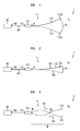
- the blade 112 is shown in two positions, one position is shown by a solid line and the other position is shown by a broken line. It is assumed that the two positions of the blade show respective maximum deflections of the tip of the blade as the blade oscillates from one position to the other. This maximum deflection is schematically shown in the figure by double-headed arrow A r . The maximum deflection is achieved when the frequency of the alternating electric signal matches the resonant frequency F r of the blade 112. In this mode of oscillation, the oscillation pattern of the blade presents one node which is represented in the figure by reference N.
- Figure 2 is an exemplary schematic representation of the apparatus 1 of figure 1 with the difference that particles such as dust and dirt, or the like, have been adhered to the body of the blade as is represented in the figure by reference numerals 121 and 122.
- the blade under faulty condition would not perform maximum deflection, and therefore, as seen in figure 2 , the amplitude of deflection A f of the tip of the blade in the presence of foul is smaller than the maximum deflection A r of the tip of the blade when the blade oscillates without the presence of foul, namely A f ⁇ A r .
- the reduction in the maximum deflection of the tip of the blade results in reduction in the volume of the airflow toward the heat generating components and thus may give rise to overeating of such components.
- Figure 3 is an exemplary schematic representation of the apparatus 1 of figure 1 with the difference that the piezofan is shown to be driven at a frequency F h which is higher than the resonant frequency F r .
- driving the blade 112 at the new oscillation frequency F h may cause the blade to oscillate with a different oscillation pattern.
- This oscillation of the blade at a frequency F h herein also referred to as secondary frequency, which is higher than the resonant frequency of the blade may exert an ejecting force on the particles 121, 122 which are adhered to the blade thereby resulting in their removal.
- the oscillation pattern of the blade may define a standing waveform W with at least two nodes N 1 and N 2 as shown in figure 3 .
- This option is preferable as it provides advantages in the cleaning operation explained below.
- cleaning of the blade may also be achieved even if the secondary oscillation frequency F h does not match the second harmonic of the resonant frequency of the blade under faulty condition but it is sufficiently higher than the latter resonant frequency so as to cause the ejection of the particles 121, 122 adhered to the blade due to higher agitation rate of the blade at such higher frequencies, as compared to the agitation rate of the blade at its resonant frequency.
- the oscillation of the blade can cause the blockage to resonate and potentially break it up or cause it to move because the blockage itself, taken as a structure, has a resonance frequency.
- the generated standing waveform W with two nodes defines a deflection amplitude which is the broadest deflection amplitude of the blade as compared to situations in which the blade is oscillating at frequencies in the vicinity of the second harmonic of the oscillation frequency of the blade.
- This broader deflection amplitude produces an additional (or optimized) effect for ejecting on the particles 121, 122 thereby assisting the overall cleaning operation of the blade 112.
- the selection of the secondary frequency F h such that it matches the second harmonic of the resonant frequency of the blade under faulty condition may be performed in a variety of manners. Those skilled in the related art will understood that determining resonant frequency of the blade under faulty condition may in principle allow for the determination of the second harmonic of the resonant frequency of the blade under faulty condition, as it is simply twice the value of the resonant frequency.
- predetermined values may be selected for the secondary oscillation frequency prior to installation of the piezofan. For example, simulation or testing operations may provide specific values for the expected resonant frequency of the blade under faulty conditions which may occur after a certain period of time and under certain conditions of operation of the fan. Such predetermined values may be stored and subsequently be used for cleaning the blade after deployment and certain usage.
- a number of values may be applied in a cyclic manner and provided that such values cover a broad enough range of frequencies, reach the second harmonic may be reached at a certain point of the process, which is the one generating the broadest displacement of the tip of the fan among the frequencies within the applied range and therefore the most effective cleaning performance (it is also noted that frequencies on either side of this specific second harmonic frequency will also generate deflection although not to the same amplitude).
- the power source may be programmed to apply the nominal second harmonic frequency for a predetermine period of time, within predetermined intervals, e.g. for five seconds every hour. As a result of this cyclic operation, dust and/or dirt would not have time to build up on the blade and therefore the fan would remain clean operating substantially at its original resonant frequency.
- a dynamic approach may be used according to which the real-time resonant frequency of the blade is monitored by momentarily turning the piezofan off and monitoring the subsequent generated signal that the damping oscillation of the blade causes on the piezoelectric element 111. This signal can then be used to calculate the resonant frequency of the blade at any given moment in time. From this assessment it is therefore possible to work out the frequency at which the second mode of oscillation of the blade (operating under faulty condition) occurs.
- a technique for the above monitoring of the real-time resonant frequency of the blade is disclosed in European patent application number 13305902.2 filed on 27 June 2013 the content of which is incorporated herein by reference in its entirety. Briefly, to this technique relates to driving the piezofan by an alternating electric excitation, in a first switching configuration, thus causing the blade of the piezofan to oscillate. Subsequently, in a second switching configuration the alternating electric excitation is disconnected and the piezoelectric element is coupled to a processor. The movement of the blade in the second switching configuration is transferred to the piezoelectric element of the piezofan which as a result generates an electric signal. The generated electric signal may be used as data for assessing the performance of the piezofan and estimate its new resonant frequency.
- One example detecting the new resonant frequency is based on the use of FFT.
- the voltage (or current) generated by the piezoelectric element of the fan with the driving signal turned off is recorded for a period of time and FFT on the recorded data is carried out.
- the frequency where the maximum voltage (or current) is given by the FFT would indicate the natural (new) resonant frequency of the blade in the new faulty condition.
- the disclosure is not limited only to this technique and other techniques available to a person skilled in the art may likewise be used.
- the blade may be caused to oscillate through a range of frequencies in an attempt to find the resonant frequency which provides the secondary mode of oscillation.
- This approach is advantageous in particular in case larger objects cause blockage of the blade oscillation.
- the blocking object such as a leaf, may also have a resonant frequency point. Varying the frequency of oscillation of the blade may cause the blocking object to resonate and therefore the blade may potentially free itself and return to normal operation.
- the selection of the secondary frequency F h of a fan using and electromagnetic driver such that it matches the second harmonic of the resonant frequency of the blade under faulty condition may be performed in similar manners as explained above (as well as in other known manners).
- the dynamic approach to monitor the real-time resonant frequency of the blade by momentarily turning the piezofan off may be performed in case of using an electromagnetic driver such that the damping oscillation of the blade moves a magnet element relative to a coil thereby inducing a current in the coil which maybe in the form of a damping oscillating signal. This signal can then be used to calculate the resonant frequency of the blade at any given moment in time in a similar fashion as described above in relation to the use of a piezoelectric material.
- an apparatus which is capable of automatically and efficiently cleaning a blade in an oscillation blade fan without the incurring operating costs and equipment downtime.
- the blade may not be operating with maximum deflection, it is still oscillating at a frequency which is higher than the resonant frequency of the blade and therefore produces some amount of airflow is.
- This situation although not optimal, may still allow for a short working period of the equipment without a need to turning the equipment off to perform manual cleaning.
- the time needed for the automatic cleaning operation of the apparatus is typically substantially shorter than the time required for a manual cleaning.
Abstract
Description
- The present invention relates to oscillation blade fans.
- Oscillation blade fans, also known as cantilever fans, are known. One typical example of using oscillation blade fans is in electric or electronic equipment were components in the equipment heat up during operation and need to be cooled off. Oscillation blade fans are typically considered to be particularly useful where space is an issue due to small size and compactness of the equipment. The oscillation of the blade causes the surrounding air to move, thereby generating airflow which is used to cool the component.
- In some examples an oscillation blade fan may use a piezoelectric element to oscillate a planar body, whereas in some other examples it may use an electromagnetic element to oscillate a planar body. Other examples may also exist. The planar body is sometimes referred to as blade or cantilever. Oscillation blade fans typically use a driving force from a driver to cause the blade to oscillate. This driving force may be obtained by activating a driver element, for example the piezoelectric element or the electromagnetic element in the examples above.
- Some embodiments feature an apparatus comprising:
- a power source, and
- an oscillation blade fan comprising a driver configured to generate a driving force in response to receiving an alternating electric excitation, and a planar body attached to the driver and configured to oscillate in response to the driving force generated by the driver,
- apply, in a first driving condition, a first alternating electric excitation to the driver at a first excitation frequency to cause the planar body to oscillate at a first oscillation frequency; and
- apply, in a second driving condition, a second alternating electric excitation to the driver at a second excitation frequency thereby causing the planar body to oscillate at a second oscillation frequency;
- According to some specific embodiments, the first oscillation frequency causes the planar body to oscillate with a first oscillation pattern comprising a first node and the second oscillation frequency causes the planar body to oscillate with a second oscillation pattern comprising a first node and a second node.
- According to some specific embodiments, the planar body has a fundamental resonant frequency under a faulty condition and the second oscillation frequency is equal to a second harmonic of said fundamental resonant frequency. According to some specific embodiments, the planar body under a faulty condition comprises at least one foreign object adhered thereto and the oscillation of the planar body under the second oscillation frequency is configured to exert an ejecting force on said at least one foreign object to cause the removal of the at least one foreign object under.
- According to some specific embodiments the apparatus is configured to select the second oscillation frequency from a plurality of available frequency values.
- According to some specific embodiments the apparatus is configured to select the second oscillation frequency by:
- disconnecting the alternating electric excitation from the driver;
- monitoring an electric signal generated by the driver in response to a damping oscillation of the planar body to obtain data corresponding to a performance of the planar body; and
- using said data to calculate said fundamental resonant frequency of the planar body under said faulty condition.
- According to some specific embodiments the apparatus is configured to cause the planar body to oscillate by applying different frequency values from a range of frequency values to determine said fundamental resonant frequency based on the oscillation pattern of the planar body corresponding to each frequency value applied.
- According to some specific embodiments the apparatus is configured to cause the planar body to oscillate by applying a number of frequency values in a cyclic manner.
- According to some specific embodiments the apparatus is configured to apply a nominal second harmonic frequency for a predetermine period of time, within predetermined intervals.
- Some embodiments feature a method comprising:
- applying by a power source, in a first driving condition, a first alternating electric excitation to a driver at a first excitation frequency;
- driving by said driver, in response to said first alternating electric excitation, a planar body to cause the planar body to oscillate at a first oscillation frequency; and
- applying by the power source, in a second driving condition, a second alternating electric excitation to the driver at a second excitation frequency;
- driving by said driver, in response to said second electric alternating excitation, the planar body to cause the planar body to oscillate at a second oscillation frequency; and
- According to some specific embodiments, oscillating the planar body at said first oscillation frequency causes the planar body to oscillate with a first oscillation pattern comprising a first node and oscillating the planar body at said second oscillation frequency causes the planar body to oscillate with a second oscillation pattern comprising a first node and a second node.
- According to some specific embodiments, the planar body has a fundamental resonant frequency under a faulty condition and the second oscillation frequency is equal to a second harmonic of said fundamental resonant frequency. According to some specific embodiments, the planar body under a faulty condition comprises at least one foreign object adhered thereto and the oscillation of the planar body under the second oscillation frequency to exerts an ejecting force on said at least one foreign object to cause the removal of the at least one foreign object under.
- According to some specific embodiments the method comprises selecting the second oscillation frequency from a plurality of available frequency values. According to some specific embodiments the method comprises selecting the second oscillation frequency by:
- disconnecting the alternating electric excitation from the driver;
- monitoring an electric signal generated by the driver in response to a damping oscillation of the planar body to obtain data corresponding to a performance of the planar body; and
- using said data to calculate said fundamental resonant frequency of the planar body under said faulty condition.
- According to some specific embodiments the method comprises causing the planar body to oscillate by applying different frequency values from a range of frequency values to determine said fundamental resonant frequency based on the oscillation pattern of the planar body corresponding to each frequency value applied.
- These and further features and advantages of the present invention are described in more detail, for the purpose of illustration and not limitation, in the following description as well as in the claims with the aid of the accompanying drawings.
-
-
Figure 1 is an exemplary schematic representation of an apparatus according to some embodiments. -
Figure 2 is an exemplary schematic representation of the apparatus offigure 1 operating under faulty condition. -
Figure 3 is an exemplary schematic representation of the apparatus offigure 1 operating to remove the faulty condition. - In the following reference will be made to piezoelectric fans. However the disclosure is not so limited and the solution proposed herein is likewise applicable to other known types of oscillation blade fans such as fans using electromagnetic elements to oscillate a planar body.
- The term planar as used herein with reference to planar body is to be understood to refer to a generally flat three-dimensional structure, wherein one dimension of the structure is substantially smaller (e.g. on or more orders of magnitude smaller) than the other two dimensions of the structure.
- Herein, the term harmonic is to be understood to refer to a component frequency of oscillation which is an integer multiple of the fundamental frequency of oscillation. Accordingly the term second harmonic of the resonant frequency is to be understood to have a frequency which is twice the fundamental resonant frequency of oscillation of the blade. Furthermore, the term fundamental resonant frequency will herein also be referred to simply as resonant frequency.
- Typically a piezoelectric fan, herein also referred to as piezofan, uses a piezoelectric element to drive a planar body. The piezoelectric element comprises a body of a solid material having the property of generating an electric signal (by accumulating electric charge) when a mechanical stress such as a pressure is applied thereupon. Conversely, such piezoelectric element exhibits a mechanical movement in response to an electric excitation (current or voltage) applied thereto. Some examples of materials exhibiting piezoelectric property are certain crystals or ceramics.
- The piezoelectric element is physically attached, e.g. bonded, to an end of a planar body (blade). The other end of the planar body is free and movable. When an alternating electric voltage (or current) is applied to the piezoelectric element, the latter exhibits an oscillating movement, causing the planar body, or blade, to oscillate at a frequency matching the drive frequency of the alternating electric signal. If the frequency of the alternating voltage (or current) is equal to the resonant frequency of the blade, the latter produces an oscillating movement at the free end thereof at said resonant frequency. The oscillation of the free end of the blade produces an air flow in a similar manner as a conventional hand fan.
- It is desirable to cause these fans to operate at the resonant frequency of the blade because oscillation at such resonant frequency typically provides the largest displacement amplitude of the free end (tip) of the blade, which results in the generation of the maximum volume of airflow by the blade.
- The oscillation amplitude of the blade is extremely sensitive to a number of parameters including operating frequency and the mass of the blade. Over the lifetime of oscillation blade fans fouling may occur on the exterior of the blade due to dust, dirt, blocking objects and the like. Adherence of dust and dirt to the body of the blade can cause a change in the mass of the blade. As a result of such change in the mass of the blade the resonant frequency of the blade may change and therefore the deflection amplitude of the blade during oscillation may be drastically reduced. This reduction in the deflection of the tip considerably reduces the fans air moving capability. An oscillation blade fan hampered with this problem would likely fail to provide an efficient cooling performance. As a result of such inefficient cooling performance, the components to be cooled may overheat and therefore component failures may occur. To ensure maximum air flow from the fan, it is therefore important to maintain operation at the resonant frequency of the blade. One approach to maintain operation at resonant frequency of the blade is to clean the blade from dust and dirt or other objects adhered thereto.
- Manual cleaning, which is sometimes used for cleaning rotating fan units is not considered as an effective solution for cleaning piezofans (or other oscillation blade fans) due their relatively small size. Furthermore, even if manual cleaning were to be considered as an option, it would incur additional operating costs and potential equipment downtime.
- It is therefore desired to provide a solution for cleaning a blade in an oscillation blade fan which would remove the need for manual cleaning operations therefore reducing operating costs, and would allow for automatically maintaining the aerodynamic performance of the oscillation blade fan.
- As used herein, the term "faulty condition" is to be understood to refer to a condition of operation of a blade in which an adverse effect causes a degradation or interruption in the otherwise normal operation of the blade. Some examples of such faulty conditions are adherence of dirt and/or dust on the body of the blade or blockage caused by an external object present on the oscillation path of the blade.
- Embodiments of the present disclosure aim at providing such solution by featuring an apparatus and a method for cleaning an oscillation blade fan.
-
Figure 1 is an exemplary schematic representation of anapparatus 1 including apower source 10 and anoscillation blade fan 11.Oscillation blade fan 11 comprises adriver 111 and a planar body (blade) 112. The driver is, in this example, a piezoelectric element. Thepower source 10 may be configured to generate alternating electric excitation (voltage or current) at aport 110 thereof. Theport 110 is electrically connected to acorresponding port 113 of thepiezofan 11 byelectric connection path 131. - The
connection path 131 is represented in the figure by a single line. However, this is only done for simplicity of illustration and is not intended to represent a limitation to a one way, or single wire, connection. Theconnection path 131 may be provided in any convenient manner, for example using two wires, one for forward connection and one for return connection between thepower source 10 and thepiezofan 11. In the latter case,ports - Under normal operation, namely in the absence of fouls or when fouls exist but their presence does not substantially degrade the operation of the piezofan, the
power source 10 may generate an alternating electric signal which is output fromport 110 and is input into thepiezoelectric element 111 throughport 113. The electric signal causes the piezoelectric element to undergo mechanical stress in the form of movements which are transferred to theblade 112 attached to thepiezoelectric element 111. As a consequence, theblade 112 is caused to oscillate at the free end 112a thereof thereby generating a flow of air in the vicinity of the free end 112a. Theblade 112 oscillates at the frequency of the alternating electric signal generated by thepower source 10. If the frequency of the alternating electric signal matches the resonant frequency of theblade 112, the blade reaches its maximum deflection for the applied electric signal. - In the embodiment of
figure 1 , theblade 112 is shown in two positions, one position is shown by a solid line and the other position is shown by a broken line. It is assumed that the two positions of the blade show respective maximum deflections of the tip of the blade as the blade oscillates from one position to the other. This maximum deflection is schematically shown in the figure by double-headed arrow Ar. The maximum deflection is achieved when the frequency of the alternating electric signal matches the resonant frequency Fr of theblade 112. In this mode of oscillation, the oscillation pattern of the blade presents one node which is represented in the figure by reference N. -
Figure 2 is an exemplary schematic representation of theapparatus 1 offigure 1 with the difference that particles such as dust and dirt, or the like, have been adhered to the body of the blade as is represented in the figure byreference numerals - As mentioned above, the adherence of
such particles - It is to be noted that that in a faulty condition as described above, the
power source 10 may still be applying an alternating electric signal with a frequency matching the nominal (non-faulty) resonant frequency of theblade 122, however due to the change in the mass of the blade, the resulting (new) resonant frequency of oscillation of the bade changes to a different value, which is not the frequency of the alternating current applied to the fan. As a result, the blade under faulty condition would not perform maximum deflection, and therefore, as seen infigure 2 , the amplitude of deflection Af of the tip of the blade in the presence of foul is smaller than the maximum deflection Ar of the tip of the blade when the blade oscillates without the presence of foul, namely Af < Ar. The reduction in the maximum deflection of the tip of the blade results in reduction in the volume of the airflow toward the heat generating components and thus may give rise to overeating of such components. - Similar to the scenario of
figure 1 , in this situation the oscillation pattern of the blade also presents one node N. -
Figure 3 is an exemplary schematic representation of theapparatus 1 offigure 1 with the difference that the piezofan is shown to be driven at a frequency Fh which is higher than the resonant frequency Fr. - As can be seen from the scenario of
figure 3 , driving theblade 112 at the new oscillation frequency Fh may cause the blade to oscillate with a different oscillation pattern. - This oscillation of the blade at a frequency Fh, herein also referred to as secondary frequency, which is higher than the resonant frequency of the blade may exert an ejecting force on the
particles - Furthermore if the
blade 112 is driven at a frequency which matches the second harmonic of the resonant frequency of the blade under faulty condition, the oscillation pattern of the blade may define a standing waveform W with at least two nodes N1 and N2 as shown infigure 3 . This option is preferable as it provides advantages in the cleaning operation explained below. However cleaning of the blade may also be achieved even if the secondary oscillation frequency Fh does not match the second harmonic of the resonant frequency of the blade under faulty condition but it is sufficiently higher than the latter resonant frequency so as to cause the ejection of theparticles - In case a blockage is present which is in contact with the blade, the oscillation of the blade can cause the blockage to resonate and potentially break it up or cause it to move because the blockage itself, taken as a structure, has a resonance frequency.
- In case the secondary frequency Fh does match the second harmonic of the oscillation frequency of the blade under faulty condition, the generated standing waveform W with two nodes defines a deflection amplitude which is the broadest deflection amplitude of the blade as compared to situations in which the blade is oscillating at frequencies in the vicinity of the second harmonic of the oscillation frequency of the blade. This broader deflection amplitude produces an additional (or optimized) effect for ejecting on the
particles blade 112. - The selection of the secondary frequency Fh such that it matches the second harmonic of the resonant frequency of the blade under faulty condition may be performed in a variety of manners. Those skilled in the related art will understood that determining resonant frequency of the blade under faulty condition may in principle allow for the determination of the second harmonic of the resonant frequency of the blade under faulty condition, as it is simply twice the value of the resonant frequency.
- In some embodiments, predetermined values may be selected for the secondary oscillation frequency prior to installation of the piezofan. For example, simulation or testing operations may provide specific values for the expected resonant frequency of the blade under faulty conditions which may occur after a certain period of time and under certain conditions of operation of the fan. Such predetermined values may be stored and subsequently be used for cleaning the blade after deployment and certain usage.
- In some embodiments, a number of values may be applied in a cyclic manner and provided that such values cover a broad enough range of frequencies, reach the second harmonic may be reached at a certain point of the process, which is the one generating the broadest displacement of the tip of the fan among the frequencies within the applied range and therefore the most effective cleaning performance (it is also noted that frequencies on either side of this specific second harmonic frequency will also generate deflection although not to the same amplitude).
- In some embodiments, the power source may be programmed to apply the nominal second harmonic frequency for a predetermine period of time, within predetermined intervals, e.g. for five seconds every hour. As a result of this cyclic operation, dust and/or dirt would not have time to build up on the blade and therefore the fan would remain clean operating substantially at its original resonant frequency.
- In some embodiments, a dynamic approach may be used according to which the real-time resonant frequency of the blade is monitored by momentarily turning the piezofan off and monitoring the subsequent generated signal that the damping oscillation of the blade causes on the
piezoelectric element 111. This signal can then be used to calculate the resonant frequency of the blade at any given moment in time. From this assessment it is therefore possible to work out the frequency at which the second mode of oscillation of the blade (operating under faulty condition) occurs. - A technique for the above monitoring of the real-time resonant frequency of the blade is disclosed in European patent application number
13305902.2 filed on 27 June 2013 - One example detecting the new resonant frequency, as described in the cited document, is based on the use of FFT. According to this example, the voltage (or current) generated by the piezoelectric element of the fan with the driving signal turned off is recorded for a period of time and FFT on the recorded data is carried out. The frequency where the maximum voltage (or current) is given by the FFT would indicate the natural (new) resonant frequency of the blade in the new faulty condition. However, the disclosure is not limited only to this technique and other techniques available to a person skilled in the art may likewise be used.
- In some embodiments the blade may be caused to oscillate through a range of frequencies in an attempt to find the resonant frequency which provides the secondary mode of oscillation. This approach is advantageous in particular in case larger objects cause blockage of the blade oscillation. In such cases, the blocking object, such as a leaf, may also have a resonant frequency point. Varying the frequency of oscillation of the blade may cause the blocking object to resonate and therefore the blade may potentially free itself and return to normal operation.
- As mentioned above, although the embodiments herein were described in relation to the use of a piezofan, other oscillation blade fans may likewise be used for the intended purpose without deviating from the scope of the present disclosure.
- For example if an electromagnetic element is used to drive the blade, similar operations as described above in relation to the embodiments of
figures 1, 2 and 3 may be performed. - Likewise the selection of the secondary frequency Fh of a fan using and electromagnetic driver such that it matches the second harmonic of the resonant frequency of the blade under faulty condition may be performed in similar manners as explained above (as well as in other known manners). In particular, the dynamic approach to monitor the real-time resonant frequency of the blade by momentarily turning the piezofan off may be performed in case of using an electromagnetic driver such that the damping oscillation of the blade moves a magnet element relative to a coil thereby inducing a current in the coil which maybe in the form of a damping oscillating signal. This signal can then be used to calculate the resonant frequency of the blade at any given moment in time in a similar fashion as described above in relation to the use of a piezoelectric material.
- In this manner, an apparatus is provided which is capable of automatically and efficiently cleaning a blade in an oscillation blade fan without the incurring operating costs and equipment downtime. In this respect it is to be noted that although during the cleaning operation, the blade may not be operating with maximum deflection, it is still oscillating at a frequency which is higher than the resonant frequency of the blade and therefore produces some amount of airflow is. This situation, although not optimal, may still allow for a short working period of the equipment without a need to turning the equipment off to perform manual cleaning. Furthermore, the time needed for the automatic cleaning operation of the apparatus is typically substantially shorter than the time required for a manual cleaning.
- The various embodiments of the present disclosure may be combined as long as such combination is compatible and/or complimentary.
- Further it is to be noted that the list of structures corresponding to the claimed means is not exhaustive and that one skilled in the art understands that equivalent structures can be substituted for the recited structure without departing from the scope of the disclosure.
- It should be appreciated by those skilled in the art that any block diagrams herein represent conceptual views of illustrative circuitry embodying the principles of the disclosure.
- It is also to be noted that the order of the steps of the method of the invention as described and recited in the corresponding claims is not limited to the order as presented and described and may vary without departing from the scope of the invention.
Claims (17)
- An apparatus comprising:- a power source, and- an oscillation blade fan comprising a driver configured to generate a driving force in response to receiving an alternating electric excitation, and a planar body attached to the driver and configured to oscillate in response to the driving force generated by the driver,wherein the power source is electrically coupled to the driver and is configured to:- apply, in a first driving condition, a first alternating electric excitation to the driver at a first excitation frequency to cause the planar body to oscillate at a first oscillation frequency; and- apply, in a second driving condition, a second alternating electric excitation to the driver at a second excitation frequency thereby causing the planar body to oscillate at a second oscillation frequency;wherein the second oscillation frequency is higher than the first oscillation frequency.
- The apparatus of claim 1, wherein the first oscillation frequency causes the planar body to oscillate with a first oscillation pattern comprising a first node and the second oscillation frequency causes the planar body to oscillate with a second oscillation pattern comprising a first node and a second node.
- The apparatus of claim 1 or claim 2, wherein the planar body has a fundamental resonant frequency under a faulty condition and the second oscillation frequency is equal to a second harmonic of said fundamental resonant frequency.
- The apparatus of any one of the preceding claims, wherein the planar body under a faulty condition comprises at least one foreign object adhered thereto and the oscillation of the planar body under the second oscillation frequency is configured to exert an ejecting force on said at least one foreign object to cause the removal of the at least one foreign object under.
- The apparatus of any one of the preceding claims, wherein the apparatus is configured to select the second oscillation frequency from a plurality of available frequency values.
- The apparatus of any one of the preceding claims 1 to 4, wherein the apparatus is configured to select the second oscillation frequency by:- disconnecting the alternating electric excitation from the driver;- monitoring an electric signal generated by the driver in response to a damping oscillation of the planar body to obtain data corresponding to a performance of the planar body; and- using said data to calculate said fundamental resonant frequency of the planar body under said faulty condition.
- The apparatus of any one of the preceding claims 1 to 4, wherein the apparatus is configured to cause the planar body to oscillate by applying different frequency values from a range of frequency values to determine said fundamental resonant frequency based on the oscillation pattern of the planar body corresponding to each frequency value applied.
- The apparatus of any one of the preceding claims 1 to 4, wherein the apparatus is configured to cause the planar body to oscillate by applying a number of frequency values in a cyclic manner.
- The apparatus of any one of the preceding claims 1 to 4, wherein the apparatus is configured to apply a nominal second harmonic frequency for a predetermine period of time, within predetermined intervals.
- The apparatus of any one of the previous claims wherein the driver comprises a piezoelectric element or an electromagnetic element.
- A method comprising:- applying by a power source, in a first driving condition, a first alternating electric excitation to a driver at a first excitation frequency;- driving by said driver, in response to said first alternating electric excitation, a planar body to cause the planar body to oscillate at a first oscillation frequency; and- applying by the power source, in a second driving condition, a second alternating electric excitation to the driver at a second excitation frequency;- driving by said driver, in response to said second electric alternating excitation, the planar body to cause the planar body to oscillate at a second oscillation frequency; andwherein the second oscillation frequency is higher than the first oscillation frequency.
- The method of claim 9, wherein oscillating the planar body at said first oscillation frequency causes the planar body to oscillate with a first oscillation pattern comprising a first node and oscillating the planar body at said second oscillation frequency causes the planar body to oscillate with a second oscillation pattern comprising a first node and a second node.
- The method of claim 9 or claim 10, wherein the planar body has a fundamental resonant frequency under a faulty condition and the second oscillation frequency is equal to a second harmonic of said fundamental resonant frequency.
- The method of any preceding claims 9 to 11, wherein the planar body under a faulty condition comprises at least one foreign object adhered thereto and the oscillation of the planar body under the second oscillation frequency to exerts an ejecting force on said at least one foreign object to cause the removal of the at least one foreign object under.
- The method of any preceding claims 9 to 12, wherein the method comprises selecting the second oscillation frequency from a plurality of available frequency values.
- The method of any preceding claims 9 to 12, wherein the method comprises selecting the second oscillation frequency by:- disconnecting the alternating electric excitation from the driver;- monitoring an electric signal generated by the driver in response to a damping oscillation of the planar body to obtain data corresponding to a performance of the planar body; and- using said data to calculate said fundamental resonant frequency of the planar body under said faulty condition.
- The method of any preceding claims 9 to 12, wherein the method comprises causing the planar body to oscillate by applying different frequency values from a range of frequency values to determine said fundamental resonant frequency based on the oscillation pattern of the planar body corresponding to each frequency value applied.
Priority Applications (1)
| Application Number | Priority Date | Filing Date | Title |
|---|---|---|---|
| EP14306013.5A EP2960521A1 (en) | 2014-06-27 | 2014-06-27 | Apparatus comprising an oscillation blade fan and method for cleaning the oscillation blade fan |
Applications Claiming Priority (1)
| Application Number | Priority Date | Filing Date | Title |
|---|---|---|---|
| EP14306013.5A EP2960521A1 (en) | 2014-06-27 | 2014-06-27 | Apparatus comprising an oscillation blade fan and method for cleaning the oscillation blade fan |
Publications (1)
| Publication Number | Publication Date |
|---|---|
| EP2960521A1 true EP2960521A1 (en) | 2015-12-30 |
Family
ID=51178837
Family Applications (1)
| Application Number | Title | Priority Date | Filing Date |
|---|---|---|---|
| EP14306013.5A Withdrawn EP2960521A1 (en) | 2014-06-27 | 2014-06-27 | Apparatus comprising an oscillation blade fan and method for cleaning the oscillation blade fan |
Country Status (1)
| Country | Link |
|---|---|
| EP (1) | EP2960521A1 (en) |
Cited By (3)
| Publication number | Priority date | Publication date | Assignee | Title |
|---|---|---|---|---|
| US20180141092A1 (en) * | 2015-05-20 | 2018-05-24 | Fisher & Paykel Appliance Limited | Fan or pump arrangement and operating method |
| CN116816698A (en) * | 2023-08-25 | 2023-09-29 | 宿迁华旭环保设备有限公司 | High stability centrifugal fan |
| EP3454467B1 (en) * | 2016-06-16 | 2023-10-04 | Huawei Technologies Co., Ltd. | Method for adjusting electromagnetically driven swing plate and electromagnetically driven swing plate apparatus |
Citations (2)
| Publication number | Priority date | Publication date | Assignee | Title |
|---|---|---|---|---|
| US4923000A (en) * | 1989-03-03 | 1990-05-08 | Microelectronics And Computer Technology Corporation | Heat exchanger having piezoelectric fan means |
| WO2008040578A1 (en) * | 2006-10-04 | 2008-04-10 | SIEMENS AKTIENGESELLSCHAFT öSTERREICH | Switched mode power supply |
-
2014
- 2014-06-27 EP EP14306013.5A patent/EP2960521A1/en not_active Withdrawn
Patent Citations (2)
| Publication number | Priority date | Publication date | Assignee | Title |
|---|---|---|---|---|
| US4923000A (en) * | 1989-03-03 | 1990-05-08 | Microelectronics And Computer Technology Corporation | Heat exchanger having piezoelectric fan means |
| WO2008040578A1 (en) * | 2006-10-04 | 2008-04-10 | SIEMENS AKTIENGESELLSCHAFT öSTERREICH | Switched mode power supply |
Cited By (5)
| Publication number | Priority date | Publication date | Assignee | Title |
|---|---|---|---|---|
| US20180141092A1 (en) * | 2015-05-20 | 2018-05-24 | Fisher & Paykel Appliance Limited | Fan or pump arrangement and operating method |
| US10987704B2 (en) * | 2015-05-20 | 2021-04-27 | Fisher & Paykel Appliances Limited | Fan or pump arrangement and operating method |
| EP3454467B1 (en) * | 2016-06-16 | 2023-10-04 | Huawei Technologies Co., Ltd. | Method for adjusting electromagnetically driven swing plate and electromagnetically driven swing plate apparatus |
| CN116816698A (en) * | 2023-08-25 | 2023-09-29 | 宿迁华旭环保设备有限公司 | High stability centrifugal fan |
| CN116816698B (en) * | 2023-08-25 | 2024-01-12 | 宿迁华旭环保设备有限公司 | High stability centrifugal fan |
Similar Documents
| Publication | Publication Date | Title |
|---|---|---|
| US9428263B2 (en) | Frequency response and health tracker for a synthetic jet generator | |
| EP2960521A1 (en) | Apparatus comprising an oscillation blade fan and method for cleaning the oscillation blade fan | |
| JP2020501200A5 (en) | ||
| US20110290286A1 (en) | Ultrasonic generator and ultrasonic cleansing apparatus | |
| TWI666385B (en) | Vibrational fluid mover active controller | |
| JP2001128487A (en) | Vibration-type linear actuator | |
| JP2016536124A (en) | Control and monitoring of atomizer vibration aperture drive frequency | |
| JP2017017939A (en) | Oscillatory power generation device and wireless sensor terminal | |
| JP7324219B2 (en) | Smart ultrasound stack and method of controlling an ultrasound system having a smart ultrasound stack | |
| US20170093267A1 (en) | Device for generating electrical power from low frequency oscillations | |
| JP5290176B2 (en) | Small electric device with charge status indicator | |
| EP2818730B1 (en) | Method and apparatus for assessment and optimization of performance of piezoelectric devices | |
| EP2960522A1 (en) | Apparatus and method for operating an oscillation blade device and a system comprising the apparatus | |
| KR102120410B1 (en) | Apparatus and method for control an actuator | |
| CN103217552A (en) | Piezoelectric type accelerating sensing system with self-excitation diagnosis | |
| EP3171038B1 (en) | Apparatus and method for operating an oscillation blade device and a system comprising the apparatus | |
| US20100309600A1 (en) | Apparatus for determining and/or monitoring a process variable | |
| CN100387946C (en) | Device for operating a vibrating unit of a vibration resonator | |
| JP6961321B1 (en) | Ultrasonic cleaner | |
| EP3454467B1 (en) | Method for adjusting electromagnetically driven swing plate and electromagnetically driven swing plate apparatus | |
| US10551611B2 (en) | Techniques for removing particulate from an optical surface | |
| KR20170019754A (en) | Pieao actuator driving method and apparatus | |
| KR101826173B1 (en) | Energy harvester having exchangeable piezoelectric element | |
| US11969817B2 (en) | Device for determining a status of an ultrasonic welding process | |
| US20220023967A1 (en) | Device for determining a status of an ultrasonic welding process |
Legal Events
| Date | Code | Title | Description |
|---|---|---|---|
| PUAI | Public reference made under article 153(3) epc to a published international application that has entered the european phase |
Free format text: ORIGINAL CODE: 0009012 |
|
| AK | Designated contracting states |
Kind code of ref document: A1 Designated state(s): AL AT BE BG CH CY CZ DE DK EE ES FI FR GB GR HR HU IE IS IT LI LT LU LV MC MK MT NL NO PL PT RO RS SE SI SK SM TR |
|
| AX | Request for extension of the european patent |
Extension state: BA ME |
|
| 17P | Request for examination filed |
Effective date: 20160630 |
|
| RBV | Designated contracting states (corrected) |
Designated state(s): AL AT BE BG CH CY CZ DE DK EE ES FI FR GB GR HR HU IE IS IT LI LT LU LV MC MK MT NL NO PL PT RO RS SE SI SK SM TR |
|
| GRAP | Despatch of communication of intention to grant a patent |
Free format text: ORIGINAL CODE: EPIDOSNIGR1 |
|
| RIC1 | Information provided on ipc code assigned before grant |
Ipc: F04D 27/00 20060101AFI20161116BHEP Ipc: F04D 33/00 20060101ALI20161116BHEP |
|
| INTG | Intention to grant announced |
Effective date: 20161208 |
|
| STAA | Information on the status of an ep patent application or granted ep patent |
Free format text: STATUS: THE APPLICATION IS DEEMED TO BE WITHDRAWN |
|
| 18D | Application deemed to be withdrawn |
Effective date: 20170419 |