-
The present disclosure relates techniques for operating an oscillation blade device.
BACKGROUND
-
Oscillation blade devices are known. One typical example of an oscillation blade device is a cantilever fan, typically used in electric or electronic equipment where components in the equipment heat up during operation and need to be cooled off. Another example of oscillation blade devices is a flexible wing structure typically used in micro-aerial vehicles, sometimes referred to as drones. Oscillation blade devices are typically considered to be particularly useful where space is an issue due to small size and compactness of the equipment. In the case of cantilever fans, the oscillation of the blade, or cantilever, causes the surrounding air to move, thereby generating airflow which is used for cooling the component. In the case of flexible wing structures, the oscillation of the blade acts as a flapping wing which causes the surrounding air to move, thereby propelling the body to which the wing structure is attached, e.g. a drone.
-
In some examples an oscillation blade devices may use a piezoelectric element to oscillate a planar body, whereas in some other examples it may use an electromagnetic element to oscillate a planar body. Other examples may also exist. The planar body is sometimes referred to as blade or cantilever. Oscillation blade devices typically use an alternating driving force from a driver to cause the blade to oscillate. This driving force may be obtained by activating a driver element, for example the piezoelectric element or the electromagnetic element in the examples above.
SUMMARY
-
Some embodiments feature an apparatus comprising:
- a power source configured for generating a plurality of alternating electric excitation signals; and
- a current meter configured to measure a current value supplied by the power source;
wherein the apparatus is configured to:
- apply, by the power source, a plurality of alternating electric excitation signals to an oscillation blade device at a corresponding plurality of excitation frequencies;
- measure, by the current meter, a plurality of current values supplied by the power source to the oscillation blade device, each current value from the plurality of current values corresponding to a respective excitation frequency from the plurality of excitation frequencies, said plurality of current values comprising a peak current value corresponding to a first excitation frequency and a trough current value corresponding to a second excitation frequency; and
- provide said plurality of current values and said plurality of excitation frequencies to a processor for determining a third excitation frequency.
-
According to some specific embodiments, said third excitation frequency is located mid-way between the first excitation frequency and the second excitation frequency and corresponds to a resonant oscillation frequency of a planar body comprised in the oscillation blade device.
-
According to some specific embodiments, said third excitation frequency is located mid-way between the first excitation frequency and the second excitation frequency and corresponds to a second harmonic of a resonant oscillation frequency of a planar body comprised in the oscillation blade device.
-
According to some specific embodiments the apparatus is configured to drive said oscillation blade device at a frequency matching the third excitation frequency.
-
Some embodiments feature a system comprising the apparatus of any one of the preceding paragraphs, further comprising:
- an oscillation blade device having a driver electrically coupled to the power source and configured to generate a driving force in response to receiving an alternating electric excitation signal from the power source, and a planar body attached to the driver and configured to oscillate in response to the driving force generated by the driver; and
- a processor configured to receive the plurality of current values and the plurality of excitation frequencies and determine said third excitation frequency.
-
According to some specific embodiments, the processor is configured to determine said third excitation frequency value as a frequency located at mid-way between a first excitation frequency and the second excitation frequency. According to some specific embodiments, the processor is configured to send a command to the power source to cause the power source to change the frequency of the alternating electric excitation signal to match the third excitation frequency.
-
Some embodiments feature a cooling assembly comprising the system as disclosed herein.
-
Some embodiments feature a micro-aerial vehicle comprising the system as disclosed herein.
-
Some embodiments feature a method for operating an apparatus, the apparatus comprising:
- a power source configured for generating a plurality of alternating electric excitation signals; and
- a current meter configured to measure a current value supplied by the power source;
wherein the method comprises:
- applying, by the power source, a plurality of alternating electric excitation signals to an oscillation blade device at a corresponding plurality of excitation frequencies;
- measuring, by the current meter, a plurality of current values supplied by the power source to the oscillation blade device, each current value from the plurality of current values corresponding to a respective excitation frequency from the plurality of excitation frequencies, said plurality of current values comprising a peak current value corresponding to a first excitation frequency and a trough current value corresponding to a second excitation frequency; and
- providing said plurality of current values and said plurality of excitation frequencies to a processor for determining a third excitation frequency, said third excitation frequency having a value between the first excitation frequency and the second excitation frequency.
-
According to some specific embodiments the method further comprises:
- determining said third excitation frequency located at mid-way between the first excitation frequency and the second excitation frequency, the third excitation frequency corresponding to a resonant oscillation frequency of a planar body comprised in the oscillation blade device.
-
According to some specific embodiments the method further comprises:
- determining said third excitation frequency located at mid-way between the first excitation frequency and the second excitation frequency, the third excitation frequency corresponding to a second harmonic of a resonant oscillation frequency of a planar body comprised in the oscillation blade device.
-
According to some specific embodiments the method further comprises:
- driving said oscillation blade device at a frequency matching the third excitation frequency.
-
According to some specific embodiments the method further comprises sending a command by the processor to the power source to cause the power source to change the frequency of the alternating electric excitation signal to match the third excitation frequency.
-
These and further features and advantages of the present invention are described in more detail, for the purpose of illustration and not limitation, in the following description as well as in the claims with the aid of the accompanying drawings.
BRIEF DESCRIPTION OF THE DRAWINGS
-
- Figure 1 is an exemplary schematic representation of an assembly comprising an apparatus according to some embodiments.
- Figure 2 is an exemplary schematic representation of the assembly comprising an apparatus of figure 1 operating under faulty condition.
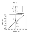
- Figure 3 is an exemplary schematic representation of oscillation characteristics of the blade comprised in the apparatus of figure 1 and a corresponding graphical representation of variation of input current as a function of frequency of oscillation of the blade.
- Figure 4A is an exemplary schematic representation of an oscillation blade in a heat sink operating at a first oscillation frequency and figure 4B is a representation of the oscillation blade of figure 4A oscillating at a second frequency according to some embodiments.
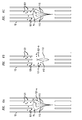
- Figure 5 is an exemplary schematic representation of oscillation characteristics of the blade comprised in the apparatus of figure 2 oscillating with a frequency that matches the second harmonic of the resonant frequency of said blade and a corresponding graphical representation of variation of input current as a function of frequency of oscillation of said blade.
- Figure 6A is an exemplary schematic representation of an oscillation blade in a heat sink operating at a first resonant frequency; figure 6B is a representation of the oscillation blade of figure 6A oscillating at a second frequency; and figure 6C is a representation of the oscillation blade of figure 6A oscillating at a third frequency, according to some embodiments.
DETAILED DESCRIPTION OF EXEMPLARY EMBODIMENTS
-
In the following reference will be made to piezoelectric fans. However the disclosure is not so limited and the solution proposed herein is likewise applicable to other known types of oscillation blade such as fans using electromagnetic elements to oscillate a planar body, or devices such as flexible wing structures useable for example in micro-aerial vehicles.
-
The term planar as used herein with reference to planar body is to be understood to refer to a generally flat three-dimensional structure, wherein one dimension of the structure is substantially smaller (e.g. one or more orders of magnitude smaller) than the other two dimensions of the structure.
-
Herein, the term harmonic is to be understood to refer to a component frequency of oscillation which is an integer multiple of the fundamental frequency of oscillation. Accordingly the term second harmonic of the resonant frequency is to be understood to have a frequency which is twice the fundamental resonant frequency of oscillation of the blade. Furthermore, the term fundamental resonant frequency will herein also be referred to simply as resonant frequency.
-
Typically a piezoelectric fan, herein also referred to as piezofan, uses a piezoelectric element to drive a planar body. The piezoelectric element comprises a body of a solid material having the property of generating an electric signal (by accumulating electric charge) when a mechanical stress such as a pressure is applied thereupon. Conversely, such piezoelectric element exhibits a mechanical movement in response to an electric excitation signal (current or voltage) applied thereto. Some examples of materials exhibiting piezoelectric property are certain crystals or ceramics.
-
The piezoelectric element is physically attached, e.g. bonded, to an end of a planar body (blade). The other end of the planar body is free and movable. When an alternating electric voltage (or current) is applied to the piezoelectric element, the latter exhibits an oscillating movement, causing the planar body, or blade, to oscillate at a frequency matching the drive frequency of the alternating electric signal. If the frequency of the alternating voltage (or current) is equal to the resonant frequency of the blade, the latter produces an oscillating movement at the free end thereof at said resonant frequency. The oscillation of the free end of the blade produces an air flow in a similar manner as a conventional hand fan.
-
It is desirable to cause these fans to operate at the resonant frequency of the blade because oscillation at such resonant frequency typically provides the largest displacement amplitude of the free end (tip) of the blade, which results in the generation of the maximum volume of airflow by the blade.
-
The oscillation amplitude of the blade is extremely sensitive to a number of parameters including operating frequency, the mass and rigidity of the blade. Over the lifetime of oscillation blade fans fouling may occur on the exterior of the blade due to dust, dirt, blocking objects and the like. Adherence of dust and dirt to the body of the blade can cause a change in the mass of the blade. As a result of such change in the mass of the blade the resonant frequency of the blade may change and therefore the deflection amplitude of the blade during oscillation may be drastically reduced. Similarly, a change or degradation in the mechanical properties of the fan over the lifetime can also alter the blade resonant frequency. For example, if the rigidity of the blade changes (i.e. due to degradation of the blade material or degradation of the bonding materials), this also alters the resonant frequency.
-
This reduction in the deflection of the tip considerably reduces the fan's air moving capabilities. An oscillation blade fan hampered with this problem would likely fail to provide an efficient cooling performance. As a result of such inefficient cooling performance, the components to be cooled may overheat and therefore component failures may occur. To ensure maximum air flow from the fan, it is therefore important to maintain operation at the resonant frequency of the blade. One approach to maintain operation at resonant frequency of the blade is to clean the blade from dust and dirt or other objects adhered thereto. Manual cleaning, which is sometimes used for cleaning rotating fan units, is not considered as an effective solution for cleaning piezofans (or other oscillation blade fans) due their relatively small size. Furthermore, even if manual cleaning were to be considered as an option, it would incur additional operating costs and potential equipment downtime.
-
It is therefore desired to provide a solution for dynamically determining the resonant frequency of an oscillation blade fan. Such determination would allow for maintaining the blade at maximum performance even if the blade is operating under faulty condition. Determining the resonant frequency of the oscillation blade fan would further allow for determining the second harmonic of such resonant frequency under faulty condition. As a consequence the blade may be made to oscillate at said second harmonic frequency and thereby fouling adhered to the blade may be removed. Such solution would reduce operating costs, and would allow for automatically maintaining the aerodynamic performance of the oscillation blade fan without the need to turn the fan off.
-
As used herein, the term "faulty condition" is to be understood to refer to a condition of operation of a blade in which an adverse effect causes a degradation or interruption in the otherwise normal operation of the blade. Some examples of such faulty conditions are adherence of dirt and/or dust on the body of the blade, blockage caused by an external object present on the oscillation path of the blade, or degradation of the mechanical properties of the blade over the lifetime. Figure 1 is an exemplary schematic representation of an apparatus 1 including a power source 10, an oscillation blade fan 11 and a current meter 12. Oscillation blade fan 11 comprises a driver 111 and a planar body (blade) 112. The driver is, in this example, a piezoelectric element. The power source 10 may be configured to generate alternating electric excitation signal (voltage or current) at a port 110 thereof. The port 110 is electrically connected to a corresponding port 113 of the piezofan 11 by electric connection path 131. The current meter 12 is configured to measure the current supplied by the power source 10 to the driver 111 of the oscillation blade fan 11 and provide values of the measured current corresponding to frequencies of the alternating electric excitation signal generated by the power source to drive the driver 111 of the oscillation blade fan 11. Such measured current values may be provided to a processor as will be described further below. The current driver may be a device which is independent from the power source 10 as represented in the figure and coupled at any convenient point to the electric connection path 131 or it may be integrated inside the power source (not shown in the figure).
-
The connection path 131 is represented in the figure by a single line. However, this is only done for simplicity of illustration and is not intended to represent a limitation to a one way, or single wire, connection. The connection path 131 may be provided in any convenient manner, for example using two wires, one for forward connection and one for return connection between the power source 10 and the piezofan 11. In the latter case, ports 110 and 113 may likewise each comprise a pair of contact points, one for forward connection and another for the return connection, and each pair of contact points may be considered to represent one port.
-
Under normal operation, namely in the absence of fouls or when fouls exist but their presence does not substantially degrade the operation of the piezofan, the power source 10 may generate an alternating electric signal which is output from port 110 and is input into the piezoelectric element 111 through port 113. The electric signal causes the piezoelectric element to undergo mechanical stress in the form of movements which are transferred to the blade 112 attached to the piezoelectric element 111. As a consequence, the blade 112 is caused to oscillate at the free end 112a thereof, thereby generating a flow of air in the vicinity of the free end 112a. The blade 112 oscillates at the frequency of the alternating electric signal generated by the power source 10. If the frequency of the alternating electric signal matches the resonant frequency of the blade 112, the blade reaches its maximum deflection for the applied electric signal. Therefore, the resonant frequency of the blade, either under normal condition (free of foul) or under faulty condition, may be considered to be the frequency at which maximum deflection of the tip of the blade is achieved.
-
In the embodiment of figure 1, the blade 112 is shown in two positions, one position is shown by a solid line and the other position is shown by a broken line. It is assumed that the two positions of the blade show respective maximum deflections of the tip of the blade as the blade oscillates from one position to the other. This maximum deflection is schematically shown in the figure by double-headed arrow A1. The maximum deflection is achieved when the frequency of the alternating electric signal matches the resonant frequency of the blade 112. In this mode of oscillation, the oscillation pattern of the blade presents one node which is represented in the figure by reference N.
-
The current meter 12 is configured to measure the current I being supplied by the power source 10 to the driver 111. This measured current value is then provided, through a connection path 141 to a processor 13 in a suitable manner and in the form of data useable by the processor 13, as known in the art, so as to enable the processor 13 to analyze the data received and provide commands based on such analysis, as will be described further below with reference to figure 3.
-
The power source is also configured to provide, through a connection path 142, to the processor 13, information related to the frequency of the alternating electric excitation signal. This information is provided to the processor 13 in a suitable manner and in the form of data useable by the processor 13, as known in the art, so as to enable the processor 13 to analyze the data received and provide commands based on such analysis, as will be described further below with reference to figure 3.
-
The processor may be of any known type of programmable device comprising hardware such as an ASIC, or a combination of hardware and software means, e.g. an ASIC and an FPGA, or at least one microprocessor and at least one memory with software modules located therein.
-
Figure 2 is an exemplary schematic representation of the apparatus 1 of figure 1 with the difference that particles such as dust and/or dirt, or the like, have been adhered to the body of the blade as is represented in the figure by reference numerals 121 and 122.
-
As mentioned above, the adherence of such particles 121, 122 to the blade, changes the mass of the blade.
-
It is to be noted that that in a faulty condition as described above, the power source 10 may still be applying an alternating electric signal with a frequency matching the nominal (non-faulty) resonant frequency of the blade 122, however due to the change in the mass of the blade, the resulting (new) resonant frequency of oscillation of the bade changes to a different value, which is not the frequency of the alternating current applied to the fan. As a result, the blade under faulty condition would not perform maximum deflection, and therefore, as seen in figure 2, the amplitude of deflection A2 of the tip of the blade in the presence of foul is smaller than the maximum deflection A1 of the tip of the blade when the blade oscillates without the presence of foul, namely A2 < A1. The reduction in the maximum deflection of the tip of the blade results in reduction in the volume of the airflow toward the heat generating components (not shown) and thus may give rise to overeating of such components.
-
Similar to the scenario of figure 1, in this situation the oscillation pattern of the blade also presents one node N.
-
Referring now to figure 3, certain oscillation characteristics of a blade used in an oscillation blade fan, for example a piezofan, are illustrated. In this figure, like elements have been provided with like reference numerals as those of figures 1 and 2. For simplicity, only the blade is shown and other elements of the oscillation blade fan, such as the driver, are not shown.
-
The lower part of figure 3 shows a non-limiting example of variation of input current as a function of the frequency of the alternating electric excitation signal applied to the fan (also herein referred to as excitation frequency).
-
The inventors have realized that for a fixed alternating input voltage, the oscillation blade fan draws a current which is dependent on the oscillating frequency of the blade which in turn is equal to the frequency of the alternating electric excitation signal applied to the fan. As can be observed in the example of figure 3 (lower part), the excitation frequency, shown in the abscissa is changed from lower values (e.g. 30 Hz) to higher values (e.g. 100 Hz). With the change of excitation frequency, the current drawn (or demanded) by the oscillation blade fan from the power source 10 (figure 1) varies as illustrated in the figure.
-
The trend in current variation with (depending on) frequency may enable to determine whether the fan is operating at, or out of, resonant frequency and what would be the value of the resonant frequency of a particular blade under normal or faulty conditions.
-
According to the present disclosure, and as shown in figure 3, the resonant frequency of the blade Fr (be it operating under non-faulty or under faulty condition) is located between a first frequency value corresponding to a current peak Ip and a second frequency value corresponding to a current trough It in the above current variation curve and its value is determined to be the frequency value located at mid-way between the first frequency value and the second frequency value.
-
Herein the term mid-way is to be understood to comprise not only the frequency value located at the exact mathematical middle point between the first frequency value and the second frequency value, but also the frequency values having a deviation from the exact middle point, such deviation being within a range of +/-0.1 Hz. For example if the frequency value located at the exact mathematical middle point between the first frequency value and the second frequency value is 70Hz, then the resonant frequency of the blade Fr may be considered to comprise any value between 69.9 Hz and 70.1 Hz. This range is believed to provide an acceptable performance for the operation of the apparatus.
-
The above solution for determining the resonant frequency allows for maintaining, or if needed adjusting, the drive frequency of the fan such that maximum displacement of the tip of the blade is ensured thereby ensuring optimum performance.
-
The upper part of figure 3 shows deflection amplitudes of the blade 112 in various operating conditions. As can be seen in the upper part of figure 3, maximum deflection of the tip of the blade is obtained at the resonant frequency Fr of the blade and operations at frequencies higher and lower than the resonant frequency provides poor air flow.
-
Therefore, by varying the frequency of the driving alternating electric signal supplied by the power source 10 over a relatively small frequency band, a range of values for the current drawn by the fan can be measured by the current meter 12 (figure 1), where a measured current value corresponds to a respective drive frequency (or a respective oscillation frequency).
-
Each measured current value from the above range of values is provided by the current meter 12 to the processor 13. Likewise, the corresponding drive (excitation) frequency value of the alternating electric excitation signal is provided by the power source 10 to the processor 13. Upon receipt of such range of current-frequency pair values the processor is configured to store such values and generate an assessment chart with a current peak Ip and a current trough It. Such assessment chart may be in any convenient form for example in the form of a table of corresponding values or in the form of a graph similar to that of figure 3.
-
The processor is further configured to find the frequency located at mid-way (+/-0.1 Hz) between a first frequency value corresponding to the current peak Ip and a second frequency value corresponding to the current trough It of said graph. Once the resonant frequency of the blade is determined by the processor 13, the latter sends a command to the power source 10, through connection path 143, to cause the power source to change the frequency of the alternating electric excitation signal to match the newly determined resonant frequency of the blade. In this manner, the resonant frequency point may be determined while the fan continues to operate. This enables dynamic adjustment of fan frequency to achieve the first mode of oscillation (fundamental resonant frequency) for maximum airflow.
-
The proposed solution therefore overcomes issues that may occur in practical operating conditions which may include adherence of dirt and/ or dust to the fan blade and degradation of performance over time as it enables operation of the fan under the actual resonant frequency of the blade even if it is operating under faulty condition.
-
Figures 4A and 4B are exemplary schematic representations of an oscillation blade in a heat sink. In these figures, unless otherwise provided, like elements have been given like reference numerals as those of previous figures 1-3, and for simplicity only the blade of the oscillation blade fan is shown. However in this case, it is assumed that the fan is installed in a heat sink 15. Under normal (non-faulty) condition and oscillating at a frequency matching the resonant frequency of the blade 112, the blade would perform the maximum deflection as shown by a broken lines 112 and broken arrow Ar in figure 4A. However, as seen in figure 4A, dust and dirt 121 floating in the surrounding air are adhered to the blade 112 thereby causing the blade to oscillate under faulty condition with an amplitude of deflection Af which is smaller than the maximum deflection Ar of the tip of the blade, as shown by solid lines 112 and solid arrow Af. The adhered dust or dirt particle is shown in the figure by reference numeral 121-a. As mentioned above, this situation is undesirable because of significant degradation in the cooling performance of the fan.
-
To overcome this problem, the technique described with reference to figure 3 may be employed to determine the new resonant frequency of the blade, namely the resonant frequency of the blade under the faulty condition. Once this new resonant frequency is determined, the frequency of the alternating driving signal (provided by the power source 10 of figure 1) may be adjusted to the new determined resonant frequency thereby causing the blade 112 to oscillate at maximum deflection again. This latter scenario is shown in figure 4B wherein the blade, with foul 121-a adhered thereto oscillates at the adjusted driving frequency (matching the newly determined resonant frequency of the blade) thereby performing the maximum deflection, as shown by solid lines 112 and solid arrow Ar.
-
In this manner, the performance of the oscillation blade fan may be maintained, or if needed corrected, in a dynamic fashion without the need to stop the operation of the fan.
-
Figure 5 is an exemplary schematic representation of oscillation characteristics of the blade oscillating with a frequency that matches the second harmonic of its fundamental resonant frequency. In this figure like elements have been given like reference numerals as those of the previous figures, and here again, for simplicity, only the blade is shown.
-
The lower part of figure 5 shows a non-limiting example of variation of input current as a function of excitation frequency applied to the fan. However, differently from the scenario of figure 3, the fan is driven at excitation frequencies which are in the vicinity of the second harmonic of the resonant frequency of the blade.
-
Similar to the scenario of figure 3, it is shown that for a fixed alternating input voltage, the oscillation blade fan draws a current which is dependent on the oscillating frequency of the blade. As can be observed in the example of figure 5 (lower part), the excitation frequency applied to the fan, shown in the abscissa, may change from lower values (e.g. 150 Hz) to higher values (e.g. 500 Hz). With the change of the excitation frequency, the current drawn (or demanded) by the oscillation blade fan from the power source 10 (figure 1) varies as illustrated in the figure.
-
Therefore the trend in current variation with (depending on) frequency would enable to determine whether the fan is operating at, or out of, the second harmonic of the resonant frequency and what would be the value of the second harmonic of the resonant frequency of a particular blade under normal or faulty conditions.
-
As shown in figure 5, the second harmonic of the resonant frequency of the blade Fr2 is located between a first frequency value corresponding to a current peak Ip and a second frequency value corresponding to a current trough It in the above current variation curve and its value is determined to be the frequency value located at mid-way between the first frequency value and the second frequency value (with deviations similar as those discussed with reference to figure 3).
-
The upper part of figure 5 shows deflection amplitudes of the blade 112 in various operating conditions. As can be seen in the upper part of figure 5, broader deflection of the tip of the blade is obtained at the frequency matching the second harmonic of the resonant frequency Fr2 of the blade and operations at frequencies higher and lower than the second harmonic of the resonant frequency provides poor blade deflection and thus poor air flow. Furthermore, when the blade 112 is driven at a frequency which matches the second harmonic of the resonant frequency of the blade under faulty condition, the oscillation pattern of the blade defines a standing waveform W with at least two nodes N1 and N2 as shown in figure 5.
-
Therefore, by varying the frequency of the driving alternating electric signal supplied by the power source 10 over a relatively small frequency band, a range of values for the current drawn by the fan can be measured by the current meter 12 (figure 1), where a measured current value corresponds to a respective drive frequency (or a respective oscillation frequency).
-
Each measured current value from the above range of values is provided by the current meter 12 to the processor 13. Likewise, the corresponding drive (excitation) frequency value of the alternating electric excitation signal is provided by the power source 10 to the processor 13. Upon receipt of such range of current-frequency pair values the processor is configured to store such values and generate an assessment chart. Such assessment chart may be in any convenient form for example in the form of a table of corresponding values or in the form of a graph in the form of a graph similar to that of figure 5.
-
The processor is further configured to find the frequency located at mid-way (+/-0.1 Hz) between a first frequency value corresponding to the current peak Ip and a second frequency value corresponding to the current trough It of said graph. Once the second harmonic of the resonant frequency of the blade is determined by the processor 13, the latter sends a command to the power source 10, through connection path 143, to cause the power source to change the frequency of the alternating electric excitation signal to match the newly determined second harmonic of the resonant frequency of the blade.
-
In this manner the second harmonic of the resonant frequency point may be determined while the fan continues to operate. This operation is advantageous as it may allow for cleaning the blade from foul adhered thereto or removing blockage from the blade's displacement path as will be described with reference to figures 6A, 6B, 6C and 7.
-
Figures 6A, 6B and 6C are exemplary schematic representations of an oscillation blade in a heat sink according to some embodiments. In these figures, unless otherwise provided, like elements have been given like reference numerals as those of previous figures, and for simplicity only the blade of the oscillation blade fan is shown. Here again, similar to the scenario of figures 4A and 4B, it is assumed that the fan is installed in a heat sink 15. Under normal (non-faulty) condition and oscillating at a frequency matching the resonant frequency of the blade 112, the blade would perform the maximum deflection as shown by broken lines 112 and broken arrow Ar in figure 6A. However, dust and dirt 121 floating in the surrounding air may adhere to the blade 112 thereby causing the blade to oscillate under faulty condition with an amplitude of deflection Af which is smaller than the maximum deflection Ar of the tip of the blade, as shown by solid lines 112 and solid arrow Af. The particle of dust or dirt is shown in the figure by reference numeral 121-a.
-
To overcome this problem, the technique described with reference to figure 5 may be employed to determine the second harmonic of the new resonant frequency of the blade under the faulty condition. Once the second harmonic of the new resonant frequency is determined, the frequency of the alternating driving signal (provided by the power source 10 of figure 1) may be adjusted to the new determined second harmonic resonant frequency thereby causing the blade 112 to oscillate at such second harmonic resonant frequency. This latter scenario is shown in figure 6B.
-
This oscillation of the blade at a second harmonic of the resonant frequency of the blade under faulty condition may exert an ejecting force on the particles which are adhered to the blade thereby resulting in their removal, as shown in the figure by reference numeral 121-b.
-
Furthermore, as seen in figure 6B (and also figure 5) when the blade 112 is driven at a frequency which matches the second harmonic of the resonant frequency of the blade under faulty condition, the oscillation pattern of the blade defines a standing waveform W with two nodes N1 and N2 (figure 5). This solution provides advantages for cleaning the blade from adhered particles because the generated standing waveform W with two nodes defines the broadest deflection amplitude as compared to the deflection at frequencies that are higher or lower than said second harmonic frequency, as can be seen in the upper part of figure 5. This broad deflection amplitude in conjunction with the higher rate of agitation of the blade (as compared to agitation under its fundamental resonant frequency) produce an optimized effect for ejecting on the particles 121-a thereby assisting the overall cleaning operation of the blade 112.
-
Once this blade is free of particles adhered thereto, or at least it is cleaner than its status prior to the agitation at the second harmonic frequency, the frequency of the alternating driving signal (provided by the power source 10 of figure 1) may be adjusted to the fundamental resonant frequency of the blade thereby causing the blade 112 to oscillate at its maximum deflection again. This latter scenario is shown in figure 6C wherein the blade, free of foul adhered thereto oscillates at the adjusted driving frequency (matching the resonant frequency of the blade) thereby performing the maximum deflection, as shown by solid lines 112 and solid arrow Ar.
-
It is to be noted that oscillating the blade at the second harmonic of its resonant frequency under faulty condition may or may not remove all the particles adhered to the body of the blade. In case, such operation removes all the particles from the blade, the blade may then be driven at its nominal resonant frequency (i.e. under clean or normal conditions) to obtain maximum deflection. On the other hand, if oscillating the blade at the second harmonic of its resonant frequency under faulty condition does not remove all the particles from the blade and certain particles still remain thereon, then the technique described with reference to figure 3 may be employed in order to determine the resonant frequency of the blade under such new faulty condition (being different from the faulty condition prior to such oscillation at said second harmonic frequency). Once the new resonant frequency of the blade is determined, the blade may then be driven at its new resonant frequency to obtain maximum deflection.
-
In the scenario of figures 6A, 6B and 6C, the processor may be programmed to follow a similar procedure as described with reference to figure 5 and further be programmed to send an additional (second) command signal to the power source to cause the power source to return to the operation in which the frequency of the alternating electric excitation signal matches the fundamental resonant frequency of the blade. In order to determine when such second command may be sent, a number of solutions may be employed. Some non-limiting examples are provided below.
-
According to one possible scenario, the processor may be programmed to send the second command signal to the power source after a certain time period has elapsed during which it is expected that the blade is free of particles or at least it is cleaner than its status prior to the agitation at the second harmonic frequency. Once the second command has been sent and the frequency of the alternating electric excitation signal is adjusted accordingly, the same operation as described with reference to the embodiment of figure 3 may be repeated to assess whether the blade is oscillating at a frequency which enables maximum deflection of the tip of the blade. Should this be the case, then no further adjustment would be needed, at least as long as new adhered particles do not alter the performance of the blade; otherwise, the same operation is repeated and further adjustments to the frequency of the alternating excitation signal are performed until the new actual resonant frequency of the blade is found and applied as driving frequency so as to ensure maximum blade deflection. According to another possible scenario, the processor may be configured to assess the performance of the blade as it oscillates according to the second harmonic of its resonant frequency with the particles adhered thereon. As the particles are removed from the blade, the second harmonic of the resonant frequency of the blade may change and therefore the processor may detect, according to the procedure described with reference to figure 5, that the blade is no longer oscillating at its current (modified) second harmonic frequency. This would indicate removal of at least some particles from the blade. In this situation, the processor may send a command to the power source to adjust the frequency of the alternating electric excitation signal to the fundamental resonant frequency of the blade as the particles (or some of the particles) adhered to the blade have been removed.
-
Alternatively the processor may be programmed to send a command to the power source to adjust the frequency of the alternating electric excitation signal to the current (modified) second harmonic of the resonant frequency of the blade and assess again whether additional variation in the determined oscillation frequency of the blade is detected due to the possibility of further particles being removed from the blade. This operation may be repeated until the processor does not detect further significant variation in the oscillation performance of the blade as it oscillates at the second harmonic of its resonant frequency which may be indicative that the blade is now substantially free of particles. At this point the processor may determine the new (fundamental) resonant frequency of the blade from the latter second harmonic resonant frequency at which no further significant variation is detected in the performance of the blade In this manner, the proposed solution provides the additional advantage of dynamically cleaning the blade without the need to stop the operation of the fan. Depending on the environment in which an equipment may be installed, e.g. outdoors or indoors, not only dust and dirt, but also larger objects may get introduced inside the housing of the equipment and therefore reach the oscillation blade fan. Such larger objects may not get directly adhered to the blade but they may block its oscillation path and thereby degrade the cooling performance of the fan. In some cases, it may not be possible to address a faulty condition involving a large object solely by adjusting the frequency of the driving electric signal to match the resonant frequency of the blade.
-
Figure 7 shows an example of such scenario. In this figure, unless otherwise provided, like elements have been given like reference numerals as those of previous figures, and for simplicity only the blade of the oscillation blade fan is shown. Here again, it is assumed that the fan is installed in a heat sink 15. Under normal (non-faulty) condition and oscillating at a frequency matching the resonant frequency of the blade 112, the blade would perform the maximum deflection as shown by broken lines 112 and broken arrow Ar in figure 6A.
-
As shown in figure 7, objects 124, 125, having larger sizes than the particles 121 are introduced inside the heat sink 15, and in particular, a large object 125 is located adjacent to the blade 112 blocking the oscillation path of the blade. Blockages which suppress the movement of the blade 121 may also alter the current demand of the oscillation blade fan for a fixed voltage input. By measuring this change in current and providing the measured value to the processor 13 (in a similar fashion as in the embodiment of figure 3), it may be possible to detect a blockage and send a warning signal which can notify operators about contingency requirements (i.e. inspection/maintenance or replacement).
-
To overcome such blockage situation, the blade 112 may be driven at a frequency rate which is higher than the resonant frequency of the blade. For example the frequency of the electric signal applied to the oscillation blade fan may be increased to values close to the second harmonic of the resonant frequency of the blade until the blade starts to oscillate in its second mode of oscillation being at the second harmonic of the resonant frequency of the blade thereby generating a wave pattern having two nodes, similar to the scenario of figure 5. This mode of operation may cause not only the removal of all, or at least some, of the particles adhered to the blade, but also may cause the removal of the blocking object 125 from the oscillation path of the blade 112. This removal may be achieved as a result of the combination of the following two effects: firstly, the blade oscillates at a higher frequency for the secondary mode to exist as compared to the single mode drive frequency; and secondly, the oscillating shape is different as two nodes are present in the wave pattern of the oscillation instead of just one. The sudden changes involving alteration in the oscillation pattern and velocity (oscillation frequency) of the blade may agitate and disturb the large object 125 and may ultimately clear it away from the oscillation path of the blade. After the removal of the large object is completed, the fan may be returned to its normal operation under resonant frequency of the blade.
-
As mentioned above, the proposed solution is not limited only to oscillation blade fans and is also applicable to other structures using an oscillation blade device such as flexible wing structures. For example in the case of flexible wing structures, the oscillation blade device is typically used for enabling a micro-aerial vehicle to fly and not for cooling an electronic component. However, it is also of utmost importance that the oscillating blade device in micro-aerial vehicles also operates at its resonant frequency to maintain an optimum performance for the device which would otherwise degrade the flying capabilities of the micro-aerial vehicle. Therefore, similar solutions as those described with reference to the embodiments related to an oscillation blade fan, are also applicable, mutatis mutandis, to the oscillation blade device used as a flexible wing structure.
-
The proposed solution offers various advantages as it allows for determining the oscillation resonant frequency of the blade under normal (non-faulty) or faulty conditions by measuring the current demand, determining the resonant frequency of the blade and accordingly adjusting the frequency of the driving alternating electric signal to match such resonant frequency at all times and while the device is in operation. In an oscillation blade fan, this solution enables the cooling mechanism to operate optimally in various environments, even under faulty conditions; whereas in a flexible wing structure, the solution enables an optimum flying performance of the micro-aerial vehicle.
-
Secondly, the proposed solution also enables a new "self cleaning" capability that, to the knowledge of the inventors, was not available in oscillation blade devices to remove dust and/or dirt and therefore reduce maintenance requirements over the operational lifetime. Thirdly, the proposed solution allows for removing a blockage caused by an object present on the oscillation path of the blade.
-
The various embodiments of the present disclosure may be combined as long as such combination is compatible and/or complimentary.
-
Further it is to be noted that the list of structures corresponding to the claimed means is not exhaustive and that one skilled in the art understands that equivalent structures can be substituted for the recited structure without departing from the scope of the disclosure.
-
It should be appreciated by those skilled in the art that any block diagrams herein represent conceptual views of illustrative circuitry embodying the principles of the disclosure.
-
It is also to be noted that the order of the steps of the method of the disclosure as described and recited in the corresponding claims is not limited to the order as presented and described and may vary without departing from the scope of the invention.