EP2997939A1 - Ophthalmological laser apparatus - Google Patents
Ophthalmological laser apparatus Download PDFInfo
- Publication number
- EP2997939A1 EP2997939A1 EP15185160.7A EP15185160A EP2997939A1 EP 2997939 A1 EP2997939 A1 EP 2997939A1 EP 15185160 A EP15185160 A EP 15185160A EP 2997939 A1 EP2997939 A1 EP 2997939A1
- Authority
- EP
- European Patent Office
- Prior art keywords
- laser
- hand piece
- cells
- matrix
- cell
- Prior art date
- Legal status (The legal status is an assumption and is not a legal conclusion. Google has not performed a legal analysis and makes no representation as to the accuracy of the status listed.)
- Granted
Links
- 239000011159 matrix material Substances 0.000 claims abstract description 41
- 238000002679 ablation Methods 0.000 claims abstract description 27
- 238000000034 method Methods 0.000 claims abstract description 24
- 238000013519 translation Methods 0.000 claims description 18
- 238000013507 mapping Methods 0.000 claims description 3
- 210000004087 cornea Anatomy 0.000 abstract description 15
- 238000001356 surgical procedure Methods 0.000 abstract description 12
- 208000002177 Cataract Diseases 0.000 abstract description 3
- 238000000605 extraction Methods 0.000 abstract description 3
- 230000003287 optical effect Effects 0.000 description 6
- WYTGDNHDOZPMIW-RCBQFDQVSA-N alstonine Natural products C1=CC2=C3C=CC=CC3=NC2=C2N1C[C@H]1[C@H](C)OC=C(C(=O)OC)[C@H]1C2 WYTGDNHDOZPMIW-RCBQFDQVSA-N 0.000 description 3
- 238000010586 diagram Methods 0.000 description 3
- 230000000994 depressogenic effect Effects 0.000 description 2
- 238000013461 design Methods 0.000 description 2
- 241000270295 Serpentes Species 0.000 description 1
- 238000013459 approach Methods 0.000 description 1
- 238000003776 cleavage reaction Methods 0.000 description 1
- 201000003046 cornea plana Diseases 0.000 description 1
- 238000012937 correction Methods 0.000 description 1
- 230000003247 decreasing effect Effects 0.000 description 1
- 238000011065 in-situ storage Methods 0.000 description 1
- 230000001788 irregular Effects 0.000 description 1
- 238000000608 laser ablation Methods 0.000 description 1
- 230000007017 scission Effects 0.000 description 1
Images

Classifications
-
- A—HUMAN NECESSITIES
- A61—MEDICAL OR VETERINARY SCIENCE; HYGIENE
- A61F—FILTERS IMPLANTABLE INTO BLOOD VESSELS; PROSTHESES; DEVICES PROVIDING PATENCY TO, OR PREVENTING COLLAPSING OF, TUBULAR STRUCTURES OF THE BODY, e.g. STENTS; ORTHOPAEDIC, NURSING OR CONTRACEPTIVE DEVICES; FOMENTATION; TREATMENT OR PROTECTION OF EYES OR EARS; BANDAGES, DRESSINGS OR ABSORBENT PADS; FIRST-AID KITS
- A61F9/00—Methods or devices for treatment of the eyes; Devices for putting-in contact lenses; Devices to correct squinting; Apparatus to guide the blind; Protective devices for the eyes, carried on the body or in the hand
- A61F9/007—Methods or devices for eye surgery
- A61F9/008—Methods or devices for eye surgery using laser
- A61F9/00802—Methods or devices for eye surgery using laser for photoablation
- A61F9/00804—Refractive treatments
-
- A—HUMAN NECESSITIES
- A61—MEDICAL OR VETERINARY SCIENCE; HYGIENE
- A61F—FILTERS IMPLANTABLE INTO BLOOD VESSELS; PROSTHESES; DEVICES PROVIDING PATENCY TO, OR PREVENTING COLLAPSING OF, TUBULAR STRUCTURES OF THE BODY, e.g. STENTS; ORTHOPAEDIC, NURSING OR CONTRACEPTIVE DEVICES; FOMENTATION; TREATMENT OR PROTECTION OF EYES OR EARS; BANDAGES, DRESSINGS OR ABSORBENT PADS; FIRST-AID KITS
- A61F9/00—Methods or devices for treatment of the eyes; Devices for putting-in contact lenses; Devices to correct squinting; Apparatus to guide the blind; Protective devices for the eyes, carried on the body or in the hand
- A61F9/007—Methods or devices for eye surgery
- A61F9/008—Methods or devices for eye surgery using laser
- A61F9/00825—Methods or devices for eye surgery using laser for photodisruption
-
- A—HUMAN NECESSITIES
- A61—MEDICAL OR VETERINARY SCIENCE; HYGIENE
- A61F—FILTERS IMPLANTABLE INTO BLOOD VESSELS; PROSTHESES; DEVICES PROVIDING PATENCY TO, OR PREVENTING COLLAPSING OF, TUBULAR STRUCTURES OF THE BODY, e.g. STENTS; ORTHOPAEDIC, NURSING OR CONTRACEPTIVE DEVICES; FOMENTATION; TREATMENT OR PROTECTION OF EYES OR EARS; BANDAGES, DRESSINGS OR ABSORBENT PADS; FIRST-AID KITS
- A61F9/00—Methods or devices for treatment of the eyes; Devices for putting-in contact lenses; Devices to correct squinting; Apparatus to guide the blind; Protective devices for the eyes, carried on the body or in the hand
- A61F9/007—Methods or devices for eye surgery
- A61F9/008—Methods or devices for eye surgery using laser
- A61F9/00802—Methods or devices for eye surgery using laser for photoablation
- A61F9/00814—Laser features or special beam parameters therefor
-
- A—HUMAN NECESSITIES
- A61—MEDICAL OR VETERINARY SCIENCE; HYGIENE
- A61F—FILTERS IMPLANTABLE INTO BLOOD VESSELS; PROSTHESES; DEVICES PROVIDING PATENCY TO, OR PREVENTING COLLAPSING OF, TUBULAR STRUCTURES OF THE BODY, e.g. STENTS; ORTHOPAEDIC, NURSING OR CONTRACEPTIVE DEVICES; FOMENTATION; TREATMENT OR PROTECTION OF EYES OR EARS; BANDAGES, DRESSINGS OR ABSORBENT PADS; FIRST-AID KITS
- A61F9/00—Methods or devices for treatment of the eyes; Devices for putting-in contact lenses; Devices to correct squinting; Apparatus to guide the blind; Protective devices for the eyes, carried on the body or in the hand
- A61F9/007—Methods or devices for eye surgery
- A61F9/008—Methods or devices for eye surgery using laser
- A61F9/00825—Methods or devices for eye surgery using laser for photodisruption
- A61F9/00827—Refractive correction, e.g. lenticle
-
- A—HUMAN NECESSITIES
- A61—MEDICAL OR VETERINARY SCIENCE; HYGIENE
- A61F—FILTERS IMPLANTABLE INTO BLOOD VESSELS; PROSTHESES; DEVICES PROVIDING PATENCY TO, OR PREVENTING COLLAPSING OF, TUBULAR STRUCTURES OF THE BODY, e.g. STENTS; ORTHOPAEDIC, NURSING OR CONTRACEPTIVE DEVICES; FOMENTATION; TREATMENT OR PROTECTION OF EYES OR EARS; BANDAGES, DRESSINGS OR ABSORBENT PADS; FIRST-AID KITS
- A61F9/00—Methods or devices for treatment of the eyes; Devices for putting-in contact lenses; Devices to correct squinting; Apparatus to guide the blind; Protective devices for the eyes, carried on the body or in the hand
- A61F9/007—Methods or devices for eye surgery
- A61F9/008—Methods or devices for eye surgery using laser
- A61F9/00825—Methods or devices for eye surgery using laser for photodisruption
- A61F9/00831—Transplantation
-
- A—HUMAN NECESSITIES
- A61—MEDICAL OR VETERINARY SCIENCE; HYGIENE
- A61F—FILTERS IMPLANTABLE INTO BLOOD VESSELS; PROSTHESES; DEVICES PROVIDING PATENCY TO, OR PREVENTING COLLAPSING OF, TUBULAR STRUCTURES OF THE BODY, e.g. STENTS; ORTHOPAEDIC, NURSING OR CONTRACEPTIVE DEVICES; FOMENTATION; TREATMENT OR PROTECTION OF EYES OR EARS; BANDAGES, DRESSINGS OR ABSORBENT PADS; FIRST-AID KITS
- A61F9/00—Methods or devices for treatment of the eyes; Devices for putting-in contact lenses; Devices to correct squinting; Apparatus to guide the blind; Protective devices for the eyes, carried on the body or in the hand
- A61F9/007—Methods or devices for eye surgery
- A61F9/008—Methods or devices for eye surgery using laser
- A61F9/00825—Methods or devices for eye surgery using laser for photodisruption
- A61F9/00836—Flap cutting
-
- A—HUMAN NECESSITIES
- A61—MEDICAL OR VETERINARY SCIENCE; HYGIENE
- A61F—FILTERS IMPLANTABLE INTO BLOOD VESSELS; PROSTHESES; DEVICES PROVIDING PATENCY TO, OR PREVENTING COLLAPSING OF, TUBULAR STRUCTURES OF THE BODY, e.g. STENTS; ORTHOPAEDIC, NURSING OR CONTRACEPTIVE DEVICES; FOMENTATION; TREATMENT OR PROTECTION OF EYES OR EARS; BANDAGES, DRESSINGS OR ABSORBENT PADS; FIRST-AID KITS
- A61F9/00—Methods or devices for treatment of the eyes; Devices for putting-in contact lenses; Devices to correct squinting; Apparatus to guide the blind; Protective devices for the eyes, carried on the body or in the hand
- A61F9/007—Methods or devices for eye surgery
- A61F9/008—Methods or devices for eye surgery using laser
- A61F9/009—Auxiliary devices making contact with the eyeball and coupling in laser light, e.g. goniolenses
-
- A—HUMAN NECESSITIES
- A61—MEDICAL OR VETERINARY SCIENCE; HYGIENE
- A61F—FILTERS IMPLANTABLE INTO BLOOD VESSELS; PROSTHESES; DEVICES PROVIDING PATENCY TO, OR PREVENTING COLLAPSING OF, TUBULAR STRUCTURES OF THE BODY, e.g. STENTS; ORTHOPAEDIC, NURSING OR CONTRACEPTIVE DEVICES; FOMENTATION; TREATMENT OR PROTECTION OF EYES OR EARS; BANDAGES, DRESSINGS OR ABSORBENT PADS; FIRST-AID KITS
- A61F9/00—Methods or devices for treatment of the eyes; Devices for putting-in contact lenses; Devices to correct squinting; Apparatus to guide the blind; Protective devices for the eyes, carried on the body or in the hand
- A61F9/007—Methods or devices for eye surgery
- A61F9/008—Methods or devices for eye surgery using laser
- A61F2009/00861—Methods or devices for eye surgery using laser adapted for treatment at a particular location
- A61F2009/0087—Lens
-
- A—HUMAN NECESSITIES
- A61—MEDICAL OR VETERINARY SCIENCE; HYGIENE
- A61F—FILTERS IMPLANTABLE INTO BLOOD VESSELS; PROSTHESES; DEVICES PROVIDING PATENCY TO, OR PREVENTING COLLAPSING OF, TUBULAR STRUCTURES OF THE BODY, e.g. STENTS; ORTHOPAEDIC, NURSING OR CONTRACEPTIVE DEVICES; FOMENTATION; TREATMENT OR PROTECTION OF EYES OR EARS; BANDAGES, DRESSINGS OR ABSORBENT PADS; FIRST-AID KITS
- A61F9/00—Methods or devices for treatment of the eyes; Devices for putting-in contact lenses; Devices to correct squinting; Apparatus to guide the blind; Protective devices for the eyes, carried on the body or in the hand
- A61F9/007—Methods or devices for eye surgery
- A61F9/008—Methods or devices for eye surgery using laser
- A61F2009/00861—Methods or devices for eye surgery using laser adapted for treatment at a particular location
- A61F2009/00872—Cornea
-
- A—HUMAN NECESSITIES
- A61—MEDICAL OR VETERINARY SCIENCE; HYGIENE
- A61F—FILTERS IMPLANTABLE INTO BLOOD VESSELS; PROSTHESES; DEVICES PROVIDING PATENCY TO, OR PREVENTING COLLAPSING OF, TUBULAR STRUCTURES OF THE BODY, e.g. STENTS; ORTHOPAEDIC, NURSING OR CONTRACEPTIVE DEVICES; FOMENTATION; TREATMENT OR PROTECTION OF EYES OR EARS; BANDAGES, DRESSINGS OR ABSORBENT PADS; FIRST-AID KITS
- A61F9/00—Methods or devices for treatment of the eyes; Devices for putting-in contact lenses; Devices to correct squinting; Apparatus to guide the blind; Protective devices for the eyes, carried on the body or in the hand
- A61F9/007—Methods or devices for eye surgery
- A61F9/008—Methods or devices for eye surgery using laser
- A61F2009/00897—Scanning mechanisms or algorithms
Definitions
- the present invention relates to a femtosecond laser ophthalmological apparatus and method that creates a flap on the cornea for LASIK refractive surgery or for other applications that require removal of corneal and lens tissue at specific locations such as in corneal transplants, stromal tunnels, corneal lenticular extraction and cataract surgery.
- LVC Laser Vision Correction
- LASIK Laser-Assisted in-situ Keratomileusis
- femtosecond laser has increasingly been used to create a LASIK flap using a series of hundreds of thousands of small laser pulses to create a cleavage plane ("cut") in the cornea.
- Femtosecond laser created corneal flaps can offer greater safety, reproducibility, predictability and flexibility over mechanical microkeratome. Furthermore, complications such as buttonhole flaps (in very steep corneas), free caps (in very flat corneas) and irregular flaps that are associated with the mechanical microkeratome are rare with the femtosecond laser. Finally, femtosecond laser systems offer a wide range of other optical-related applications to include corneal transplants, stromal tunnels, corneal lenticular extraction and cataract surgery.
- Rathjen proposes guiding the laser through a mirror-lens relay arm into a hand piece and attaching a suction unit at the end of the hand piece with a vacuum pump to secure the hand piece on the patient's eye.
- the system uses a line scanning pattern method of ablation.
- the line pattern uses a faster scanner to create a pattern and moves the pattern using a slower scanner to cover the necessary area of ablation.
- the pattern can be moved in a variety of ways to include rotation about a central axis to ablate the necessary area.
- This method of laser ablation is in contrast to the traditional method used by fixed delivery systems.
- the fixed delivery systems are able to map the area of the cornea out and have enough laser power and scanning speed to ablate the necessary pattern using a laser spot.
- This method is not available to a system that needs to guide the laser through an optical unit (mirror-lens relay arm) into a mobile hand piece.
- the laser pulse line scanning pattern has to be precisely aligned to be perpendicular with the trajectory of the translation motor after passing through the delivery arm.
- Rathjen compensates with a rotation element to maintain the perpendicular trajectory. This creates a more complex, less reliable and potentially more expensive apparatus.
- any pattern created by lines will have an inherent width (at a minimum the length of the line) that limits the flexibility of 3D trajectories available.
- Third, centering the suction ring on the eye while it is attached to the hand piece is cumbersome for surgeons. It requires additional fine movements to align laser spot center and eye center after the suction ring is connected to the eye.
- the current design uses a mirror-lens relay optical arm to deliver the laser beam from the main cabinet into the hand piece. Placing lenses in an optical arm amplifies alignment errors and creates a more complex module.
- an ophthalmological apparatus utilizes a femtosecond laser beam that travels through a rotating mirror set module as opposed to a mirror-lens relay optical arm. Using only mirrors simplifies the optical system's design and operation.
- the rotating mirror set module is attached to the main cabinet and a hand piece where the laser beam is deflected by a two dimensional XY scanner device into a predetermined pattern of laser pulses.
- the ablation pattern required is determined by dividing the ablation area into a matrix grid around 12x12mm centered on the cornea of the eye.
- the matrix grid is further divided into individual cells and ablation is completed in each individual cell in a predetermined sequence until all cells in the matrix grid have been ablated.
- the suction ring is designed to be aligned and attached to eye center separate from the hand piece. Once the suction ring is fixed on the eye, the hand piece is moved to connect with the suction ring via a slide lock mechanism. This method ensures the suction ring and hand piece are both properly aligned.
- a method of ablating eye tissue using an ophthalmological apparatus includes generating a pulsed laser beam from a femtosecond laser and directing the generated laser beam through a beam expander.
- a computer controlled electronically activated shutter and a rotating mirror set module are used so that the laser beam enters the hand piece module at normal incidence to its entrance plane.
- the laser beam is applied to a two dimensional XY scanner in the hand piece module to generate a predetermined scanning pattern of laser pulses (henceforth referred to as "scanning pattern").
- the scanning pattern is applied coaxially to a zoom-able scan focusing lens supported by an XYZ translation motor in the hand piece module, and it focuses the scanning pattern onto the patient's eye.
- the scanning pattern is moved by a XYZ translation motor in a predetermined pattern onto a patient's eye by mapping the area of the cornea into a matrix grid consisting of a plurality of individual cells.
- the scanning pattern completes ablation in a cell and then moves to complete ablation in the next cell in a predetermined sequence until ablation in all cells of the matrix is complete.
- the sequence of scanning cells can vary. It is generally most efficient to move from one cell to an adjacent cell until the completion of the scanning in all cells of the matrix.
- Each cell can be scanned with a random generated scan of laser beam spots on with any scan pattern desired.
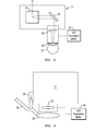
- a foot switch 13 and the user interface 12 are connected to a computer 14 inside the main cabinet 11.
- laser pulses are generated with a femtosecond laser 15 that is guided through an attached rotating mirror set module 16.
- the ophthalmological apparatus 10 has the main cabinet 11 and a hand piece module 17 connected to either end of the rotating mirror set module 16.
- a laser beam expander 18 is positioned in the main cabinet 11 to enlarge the laser beam spot size before it is directed through the rotating mirror set module 16.
- the laser beam passes through the rotating mirror set module 16 having mirrors 20, 21, and 22, but can have more than three mirrors as desired, and into the hand piece module 17 at normal incidence to the two dimensional XY scanner 19.
- the two dimensional XY scanner 19 deflects the laser beam to create a scanning pattern of laser pulses.
- a zoom-able scan focusing lens 22 is used to reduce the laser beam spot size.
- the lens is supported by a XYZ translation motor 24 in the hand piece module 17 that is used to move the scanning pattern according to a predetermined sequence onto the patient's eye 23.
- the light pulse generator is a femtosecond laser 15, which may have a pulse width less than 1000 femtoseconds and a pulse repetition rate greater than 10 KHz.
- the laser beam spot size is enlarged by a beam expander 18 and is then blocked by a shutter 25 until the foot switch 13 is depressed. While the foot switch 13 is depressed, the beam is allowed to continue through the rotating mirror set module 16 and into the hand piece module 17 as shown in Figure 2 .
- the laser beam is deflected by the two dimensional XY scanner 19 into a predetermined scanning pattern and deflected by a mirror 39 to ablate the cornea based on a matrix grid sequence.
- the cornea is divided into a multitude of individual cells, as seen in Figures 5, 6 and 7 , that make up a matrix grid that covers the entire area of the cornea.
- the laser will sequentially complete scanning in one cell before moving on to the next cell and continue doing so until scanning in all cells of the matrix is complete.
- Each cell 31 in the matrix can be scanned with a random generated scan of laser beam spots 34 to fully scan the cell 31 or can be scanned with any scan pattern desired.
- the scanning pattern may have a laser pulse repetition rate up to 2 MHz.
- a compact, low F-number (high numeric aperture) zoom-able scan focusing lens 22 is mounted on an XYZ translation motor 24 to reduce the spot size of the laser beam to less than 3 microns.
- the translation motor 24 supports the zoom-able scan focusing lens 22 and has a smaller size and higher focusing capability than the F-theta lens that is currently most commonly used in femtosecond ophthalmic systems.
- the higher focusing capability generates a smaller laser beam spot size that reduces the required energy based on the same energy density. Reduced energy levels form smaller cavitation bubbles and are absorbed faster by the surrounding tissue. This also means the acoustic wave impact caused by the photo disruption is reduced.
- the smaller lens size can be incorporated into a smaller hand piece module that makes it easier to integrate with existing UV laser ophthalmic apparatus for LASIK.
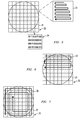
- a key point of the present invention is dividing a scanning area into a matrix grid 32 of cells 31 and then completing the scanning of each individual cell 31 before moving on to the next cell 31 in a sequence 33.
- Each cell 31 can be scanned with a random generated scan of beam spots 34 or with any other scan pattern within each cell 31 to cover the entire cell, as shown for one cell in Figure 5 , before moving to the next cell.
- the cells 31 are placed in a matrix grid 32 and then each cell 31 is scanned with the laser beam before moving in any pattern desired, such as a random generated scan 34, within the cell before going to the next cell 31.
- the area of the cornea mapped as a matrix grid 32 consist of individual cells 31 and a horizontal snake or serpentine scanning path or sequence 33 used to cover the grid as each individual cell of the matrix is scanned along a horizontal axis. Each cell is fully scanned before scanning the next cell in a horizontal row of cells one at a time until the scanning of the grid is complete.
- Figure 6 shows the sequence 33 of scanning from cell to cell with the scanning being completed from one cell 31 to an adjacent cell 31 for all cells in a row of the matrix before scannning the next row until all scanning is complete.
- Figure 7 shows a spiral sequence 33 for scanning each cell 31 in the outer most ring of cells 31 and continues until all cells are scanned.
- An XYZ translation motor 24 is located in the hand piece 17 and has a focusing lens 22 mounted thereto.
- the XYZ translation motor 24 is positioned for receiving a predetermined pattern of laser pulses from the laser scanner 19 which scans the predetermined pattern of laser pulses onto the patient's eye 23 to complete the ablation in an individual cell 31 of the scan pattern 32.
- a detachable suction ring 26 is placed onto the patient's eye 23 and then attached to the hand piece 17 with a slide lock mechanism 28 for scanning the eye 23.
- the ablation area is mapped as a matrix grid 32 consisting of a multitude of individual cells 31 and ablation of an individual cell 31 of the matrix grid 32 are completed one by one until all cells 31 of the mapped matrix grid 32 of the patient's eye 23 have been ablated.
- the method of ablating eye tissue in accordance with the present invention includes the mapping of an ablation area for a patient's eye as a matrix grid 32 consisting of a multitude of individual cells 31 and then generating a laser beam of laser spots from a femtosecond laser source 15.
- the generated laser beam from the femtosecond laser source 15 is then directed through a rotating mirror set module 16 so the laser beam enters a hand piece module 17 at normal incidence to its entrance plane.
- the generated laser beam is applied to a laser scanner 19 in the hand piece 17 to generate a predetermined scanning pattern of laser pulses.
- An XYZ translation motor 24 is then selected which supports a zoom-able scan focusing lens 22.
- the predetermined scanning pattern of laser pulses generated by the laser scanner is then applied onto the translation motor 24 supported zoom-able scan focusing lens 22 which focuses the predetermined scanning pattern of laser pulses onto a patient's eye 23 and scanning the predetermined pattern of laser pulses onto the patient's eye 23 to complete the ablation in an individual cell 31.
- the ablation of an individual cell 31 of a matrix 32 is then completed one cell at a time until all cells 31 of the mapped matrix 32 of the patient's eye 23 has been ablated.
- the matrix grid 32 ablation sequence may be a serpentine like sequence 33 of individual cells as shown in Figure 6 or may be a spiral sequence 36 as shown in Figure 7 of individual cells 31.
- the process may include selecting an XYZ translation motor 24 supported zoom-able scan focusing lens 22 in an adjustable hand piece module 17.
- the process may also include mounting the femtosecond laser source 15 in a main cabinet 11 and the laser scanner 19 in the hand piece module 17 connected to the main cabinet 11 by a rotating mirror set module 16.
- Other steps in the process may include selecting a beam expander 18 and applying the femtosecond laser 15 to the beam expander 18 in the main cabinet 11 to enlarge the femtosecond laser beam spot and selecting a hand piece 17 having a detachable suction ring 26 connected by a slide lock mechanism 28 for attaching the hand piece 17 to a patient's eye 23.
Abstract
Description
- The present invention relates to a femtosecond laser ophthalmological apparatus and method that creates a flap on the cornea for LASIK refractive surgery or for other applications that require removal of corneal and lens tissue at specific locations such as in corneal transplants, stromal tunnels, corneal lenticular extraction and cataract surgery.
- The use of an excimer laser to modify the shape of the cornea is called Laser Vision Correction (LVC). Currently the most popular method is called LASIK (Laser-Assisted in-situ Keratomileusis) and accounts for approximately 85% of all LVC preformed. Traditionally, during LASIK, the surgeon uses an instrument called a mechanical microkeratome (physical blade) to create a flap on the cornea. However, over the last few years, femtosecond laser has increasingly been used to create a LASIK flap using a series of hundreds of thousands of small laser pulses to create a cleavage plane ("cut") in the cornea.
- Femtosecond laser created corneal flaps can offer greater safety, reproducibility, predictability and flexibility over mechanical microkeratome. Furthermore, complications such as buttonhole flaps (in very steep corneas), free caps (in very flat corneas) and irregular flaps that are associated with the mechanical microkeratome are rare with the femtosecond laser. Finally, femtosecond laser systems offer a wide range of other optical-related applications to include corneal transplants, stromal tunnels, corneal lenticular extraction and cataract surgery.
- However, several limitations are associated with current femtosecond laser systems: The overall size of current femtosecond laser systems are much larger than mechanical microkeratome systems. Concurrently, with the exception to Ziemer Ophthalmic AG's Femto LDV systems, current femtosecond laser systems require the patient's eye to be aligned to a fixed laser beam delivery point. These two factors negatively impacts patient and surgeon comfort during surgery. Whereas the corneal flap creation by mechanical microkeratome and subsequent corneal reshaping by an excimer laser system can be done without moving the patient, the size of femtosecond laser systems and fixed delivery require patients to be transferred from one location to another. It is not uncommon for patients to have to move to a separate room to receive corneal reshaping. The femtosecond laser created flaps also increases the surgery time (decreased workflow) as there is often a necessary wait time after laser flap creation (for cavitation gas bubbles to diffuse) before the patient can be moved. This is also a significant reason why most Ophthalmology clinics in the world still employ mechanical microkeratome for more efficient workflow.
- Pat. No.
7,621,637 by Rathjen describes an ophthalmological apparatus that Ziemer Ophthalmic AG's Femto LDV series currently utilizes, and it addresses the size, flexibility of delivery and surgery time (small laser spot size for smaller cavitation gas bubbles) issues previously mentioned. Rathjen proposes guiding the laser through a mirror-lens relay arm into a hand piece and attaching a suction unit at the end of the hand piece with a vacuum pump to secure the hand piece on the patient's eye. The system uses a line scanning pattern method of ablation. The line pattern uses a faster scanner to create a pattern and moves the pattern using a slower scanner to cover the necessary area of ablation. The pattern can be moved in a variety of ways to include rotation about a central axis to ablate the necessary area. This method of laser ablation is in contrast to the traditional method used by fixed delivery systems. The fixed delivery systems are able to map the area of the cornea out and have enough laser power and scanning speed to ablate the necessary pattern using a laser spot. This method is not available to a system that needs to guide the laser through an optical unit (mirror-lens relay arm) into a mobile hand piece. There are several disadvantages to Rathjen's method of approach. First, to avoid pattern distortion on the eye created by the translation motor during rotation of the line, the laser pulse line scanning pattern has to be precisely aligned to be perpendicular with the trajectory of the translation motor after passing through the delivery arm. Rathjen compensates with a rotation element to maintain the perpendicular trajectory. This creates a more complex, less reliable and potentially more expensive apparatus. Second, any pattern created by lines will have an inherent width (at a minimum the length of the line) that limits the flexibility of 3D trajectories available. Third, centering the suction ring on the eye while it is attached to the hand piece is cumbersome for surgeons. It requires additional fine movements to align laser spot center and eye center after the suction ring is connected to the eye. Finally, the current design uses a mirror-lens relay optical arm to deliver the laser beam from the main cabinet into the hand piece. Placing lenses in an optical arm amplifies alignment errors and creates a more complex module. - In the present invention an ophthalmological apparatus utilizes a femtosecond laser beam that travels through a rotating mirror set module as opposed to a mirror-lens relay optical arm. Using only mirrors simplifies the optical system's design and operation. The rotating mirror set module is attached to the main cabinet and a hand piece where the laser beam is deflected by a two dimensional XY scanner device into a predetermined pattern of laser pulses. The ablation pattern required is determined by dividing the ablation area into a matrix grid around 12x12mm centered on the cornea of the eye. The matrix grid is further divided into individual cells and ablation is completed in each individual cell in a predetermined sequence until all cells in the matrix grid have been ablated. This method eliminates the need for compensating optics, rotation elements or trajectory limitations as encountered in the prior art. The suction ring is designed to be aligned and attached to eye center separate from the hand piece. Once the suction ring is fixed on the eye, the hand piece is moved to connect with the suction ring via a slide lock mechanism. This method ensures the suction ring and hand piece are both properly aligned.
- A method of ablating eye tissue using an ophthalmological apparatus includes generating a pulsed laser beam from a femtosecond laser and directing the generated laser beam through a beam expander. A computer controlled electronically activated shutter and a rotating mirror set module are used so that the laser beam enters the hand piece module at normal incidence to its entrance plane. The laser beam is applied to a two dimensional XY scanner in the hand piece module to generate a predetermined scanning pattern of laser pulses (henceforth referred to as "scanning pattern"). The scanning pattern is applied coaxially to a zoom-able scan focusing lens supported by an XYZ translation motor in the hand piece module, and it focuses the scanning pattern onto the patient's eye. The scanning pattern is moved by a XYZ translation motor in a predetermined pattern onto a patient's eye by mapping the area of the cornea into a matrix grid consisting of a plurality of individual cells. The scanning pattern completes ablation in a cell and then moves to complete ablation in the next cell in a predetermined sequence until ablation in all cells of the matrix is complete. The sequence of scanning cells can vary. It is generally most efficient to move from one cell to an adjacent cell until the completion of the scanning in all cells of the matrix. Each cell can be scanned with a random generated scan of laser beam spots on with any scan pattern desired.
- The accompanying drawings, which are included to provide further understanding of the invention, constitute a part of the specification and illustrate the invention together with the description to explain the principles of the invention.
- In the drawings:
-
FIG. 1 is a drawing of the exterior of the critical modules of the apparatus and how the modules fit together to form the femtosecond laser ophthalmological surgery apparatus; -
FIG. 2 is a block diagram of a femtosecond laser ophthalmologic surgery apparatus in accordance with the present invention; -
FIG. 3 is a diagrammatic view of the hand piece module ofFigure 1 and 2 showing the change in femtosecond laser characteristic as it exits the mirror set module, and applied to the two dimensional XY scanner and then focused by the translation motor supported zoom-able scan focusing lens; -
FIG. 4 is a side diagrammatic view of the hand piece module and the slide lock mechanism of the suction ring; -
FIG. 5 is the area of a cornea mapped as a matrix grid consisting of individual cells and the scanning pattern in each individual cell of the matrix; -
FIG. 6 is a diagram of a horizontal serpentine sequence to scan from cell to cell of the matrix; and -
FIG. 7 is a diagram of a spiral sequence to scan from cell to cell of the matrix. - The laser
ophthalmological surgery apparatus 10 in accordance with the present invention as seen in the drawings, especially as seen inFigures 1,2 and3 , includes auser interface 12 connected to amain cabinet 11. Afoot switch 13 and theuser interface 12 are connected to acomputer 14 inside themain cabinet 11. Within themain cabinet 11, laser pulses are generated with afemtosecond laser 15 that is guided through an attached rotating mirror setmodule 16. Theophthalmological apparatus 10 has themain cabinet 11 and ahand piece module 17 connected to either end of the rotating mirror setmodule 16. Alaser beam expander 18 is positioned in themain cabinet 11 to enlarge the laser beam spot size before it is directed through the rotating mirror setmodule 16. The laser beam passes through the rotating mirror setmodule 16 havingmirrors hand piece module 17 at normal incidence to the twodimensional XY scanner 19. The twodimensional XY scanner 19 deflects the laser beam to create a scanning pattern of laser pulses. Inside the hand piece, a zoom-ablescan focusing lens 22 is used to reduce the laser beam spot size. The lens is supported by aXYZ translation motor 24 in thehand piece module 17 that is used to move the scanning pattern according to a predetermined sequence onto the patient'seye 23. - Following the light path in greater detail, the light pulse generator is a
femtosecond laser 15, which may have a pulse width less than 1000 femtoseconds and a pulse repetition rate greater than 10 KHz. The laser beam spot size is enlarged by abeam expander 18 and is then blocked by ashutter 25 until thefoot switch 13 is depressed. While thefoot switch 13 is depressed, the beam is allowed to continue through the rotating mirror setmodule 16 and into thehand piece module 17 as shown inFigure 2 . Inside thehand piece module 17, the laser beam is deflected by the twodimensional XY scanner 19 into a predetermined scanning pattern and deflected by amirror 39 to ablate the cornea based on a matrix grid sequence. The cornea is divided into a multitude of individual cells, as seen inFigures 5, 6 and 7 , that make up a matrix grid that covers the entire area of the cornea. The laser will sequentially complete scanning in one cell before moving on to the next cell and continue doing so until scanning in all cells of the matrix is complete. Eachcell 31 in the matrix can be scanned with a random generated scan of laser beam spots 34 to fully scan thecell 31 or can be scanned with any scan pattern desired. The scanning pattern may have a laser pulse repetition rate up to 2 MHz. - Inside the
hand piece 17, as more clearly seen inFigures 3 and 4 , a compact, low F-number (high numeric aperture) zoom-ablescan focusing lens 22 is mounted on anXYZ translation motor 24 to reduce the spot size of the laser beam to less than 3 microns. Thetranslation motor 24 supports the zoom-ablescan focusing lens 22 and has a smaller size and higher focusing capability than the F-theta lens that is currently most commonly used in femtosecond ophthalmic systems. The higher focusing capability generates a smaller laser beam spot size that reduces the required energy based on the same energy density. Reduced energy levels form smaller cavitation bubbles and are absorbed faster by the surrounding tissue. This also means the acoustic wave impact caused by the photo disruption is reduced. Furthermore, the smaller lens size can be incorporated into a smaller hand piece module that makes it easier to integrate with existing UV laser ophthalmic apparatus for LASIK. - The
hand piece 17 is attached to the eye via a cleardisposable suction ring 26 as shown inFigure 4 . Thedisposable suction ring 26 is placed on theeye 23 and secured using the low pressure created and maintained by avacuum pump 27. Thehand piece 17 is connected to the detachabledisposable suction ring 26 by a slide lock mechanism. The laser beam passes through thedisposable suction ring 26 onto the cornea of theeye 23. Thesuction ring 26 is placed on theeye 23 and aligned using a microscope. Once aligned, the hand piece is manually pushed into the proper position as dictated by thesuction ring 26. Since thesuction ring 26 is completely clear when viewed under the microscope, alignment is easily performed. Ahandle 30 has the vacuum line connected thereinto and has aslidelock mechanism 28 as seen inFigure 4 . - It will be clear at this point that a key point of the present invention is dividing a scanning area into a
matrix grid 32 ofcells 31 and then completing the scanning of eachindividual cell 31 before moving on to thenext cell 31 in a sequence 33. Eachcell 31 can be scanned with a random generated scan of beam spots 34 or with any other scan pattern within eachcell 31 to cover the entire cell, as shown for one cell inFigure 5 , before moving to the next cell. Thecells 31 are placed in amatrix grid 32 and then eachcell 31 is scanned with the laser beam before moving in any pattern desired, such as a random generatedscan 34, within the cell before going to thenext cell 31. InFigure 6 the area of the cornea mapped as amatrix grid 32 consist ofindividual cells 31 and a horizontal snake or serpentine scanning path or sequence 33 used to cover the grid as each individual cell of the matrix is scanned along a horizontal axis. Each cell is fully scanned before scanning the next cell in a horizontal row of cells one at a time until the scanning of the grid is complete.Figure 6 shows the sequence 33 of scanning from cell to cell with the scanning being completed from onecell 31 to anadjacent cell 31 for all cells in a row of the matrix before scannning the next row until all scanning is complete.Figure 7 shows a spiral sequence 33 for scanning eachcell 31 in the outer most ring ofcells 31 and continues until all cells are scanned. - The present
ophthalmological apparatus 10 can be seen as having amain cabinet 11 and ahand piece module 17 connected to themain cabinet 11 by a rotating mirror setmodule 16 having a plurality ofmirrors femtosecond laser source 15 is positioned in themain cabinet 11. The laser beam output of laser pulses is manually activated by ashutter 25 mounted between thefemtosecond laser source 15 and the rotating mirror setmodule 16. Alaser beam expander 18 is positioned to enlarge the femtosecond laser beam laser pulses while a twodimensional XY scanner 19 laser scanner is positioned in thehand piece module 17 for scanning the laser beam into a predetermined pattern of laser pulses. AnXYZ translation motor 24 is located in thehand piece 17 and has a focusinglens 22 mounted thereto. TheXYZ translation motor 24 is positioned for receiving a predetermined pattern of laser pulses from thelaser scanner 19 which scans the predetermined pattern of laser pulses onto the patient'seye 23 to complete the ablation in anindividual cell 31 of thescan pattern 32. Adetachable suction ring 26 is placed onto the patient'seye 23 and then attached to thehand piece 17 with aslide lock mechanism 28 for scanning theeye 23. The ablation area is mapped as amatrix grid 32 consisting of a multitude ofindividual cells 31 and ablation of anindividual cell 31 of thematrix grid 32 are completed one by one until allcells 31 of the mappedmatrix grid 32 of the patient'seye 23 have been ablated. - The method of ablating eye tissue in accordance with the present invention includes the mapping of an ablation area for a patient's eye as a
matrix grid 32 consisting of a multitude ofindividual cells 31 and then generating a laser beam of laser spots from afemtosecond laser source 15. The generated laser beam from thefemtosecond laser source 15 is then directed through a rotating mirror setmodule 16 so the laser beam enters ahand piece module 17 at normal incidence to its entrance plane. The generated laser beam is applied to alaser scanner 19 in thehand piece 17 to generate a predetermined scanning pattern of laser pulses. AnXYZ translation motor 24 is then selected which supports a zoom-ablescan focusing lens 22. The predetermined scanning pattern of laser pulses generated by the laser scanner is then applied onto thetranslation motor 24 supported zoom-ablescan focusing lens 22 which focuses the predetermined scanning pattern of laser pulses onto a patient'seye 23 and scanning the predetermined pattern of laser pulses onto the patient'seye 23 to complete the ablation in anindividual cell 31. The ablation of anindividual cell 31 of amatrix 32 is then completed one cell at a time until allcells 31 of the mappedmatrix 32 of the patient'seye 23 has been ablated. Thematrix grid 32 ablation sequence may be a serpentine like sequence 33 of individual cells as shown inFigure 6 or may be a spiral sequence 36 as shown inFigure 7 ofindividual cells 31. The process may include selecting anXYZ translation motor 24 supported zoom-ablescan focusing lens 22 in an adjustablehand piece module 17. The process may also include mounting thefemtosecond laser source 15 in amain cabinet 11 and thelaser scanner 19 in thehand piece module 17 connected to themain cabinet 11 by a rotating mirror setmodule 16. Other steps in the process may include selecting abeam expander 18 and applying thefemtosecond laser 15 to thebeam expander 18 in themain cabinet 11 to enlarge the femtosecond laser beam spot and selecting ahand piece 17 having adetachable suction ring 26 connected by aslide lock mechanism 28 for attaching thehand piece 17 to a patient'seye 23. - It should be clear at this time that a femtosecond laser eye surgery method and apparatus has been described which highlights the advantages of delivering a laser beam remotely using a rotating mirror set module (as opposed to mirrors and lenses) into a hand piece module and using a matrix grid of cells to sequentially organize and ablate tissue. However, it should be clear that the present invention is not to be considered as limited to the forms shown which are to be considered illustrative rather than restrictive.
Claims (14)
- An ophthalmological apparatus (10) comprising:a main cabinet (11);a hand piece (17) module attached to said main cabinet (11) by a rotating mirror set module (16);a femtosecond laser source (15) positioned in said main cabinet (11) and having a laser beam output of laser pulses directed to said hand piece module (17) through said rotating mirror set module (16) ;a laser scanner (19) positioned in said hand piece module (17) for scanning said received laser beam into a predetermined pattern of laser pulses;an XYZ translation motor (24) located in said hand piece;a focusing lens (22) mounted to said XYZ translation motor (24) and positioned for receiving said predetermined pattern of laser pulses from said laser scanner (19), and scanning the predetermined pattern of laser pulses onto a patient's eye (23) by completing ablation in each of a series of individual cells in a matrix of cells; anda detachable suction ring (26) located in said hand piece and adapted for placement onto a patient's eye (23);whereby an ablation area mapped as a matrix (32) of a plurality of individual cells is ablated one cell at a time until all the cells (31) of the mapped matrix (32) of a patient's eye (23) have been ablated.
- The ophthalmological apparatus (10) in accordance with claim 1 including a laser beam expander (18) mounted between said femtosecond laser source (15) and said rotating mirror set module (16) to enlarge the output of said femtosecond laser beam laser pulses.
- The ophthalmological apparatus (10) in accordance with claim 2 in which said detachable suction ring (26) in said hand piece (17) includes a slide lock mechanism (28) for locking the suction ring in place.
- The ophthalmological apparatus (10) in accordance with claim 2 in which said laser scanner is a two dimensional XY scanner (19).
- The ophthalmological apparatus (10) in accordance with claim 1 in which said rotating mirror set module (16) has a plurality of mirrors (20,21,22) therein.
- The ophthalmological apparatus (10) in accordance with claim 2 including a manually activated shutter (25) mounted between said femtosecond laser source (15) and said rotating mirror set module (16).
- A method of ablating a surface area comprising the steps of:mapping an ablation area as a matrix (32) consisting of a plurality of individual cells (31);generating a laser beam from a femtosecond laser source (15);directing the generated laser beam through a rotating mirror set module (16) so that the laser beam enters a hand piece module (17) at normal incidence to its entrance plane;applying the generated laser beam to a laser scanner (19) in the hand piece (17) to generate a predetermined scanning pattern (33,35) of laser pulses;selecting an XYZ translation motor (24) supported zoom-able scan focusing lens (22);applying the predetermined scanning pattern (33,35) of laser pulses generated by said laser scanner (19) onto said translation motor supported zoom-able scan focusing lens (22);focusing the predetermined scanning pattern (33,35) of laser pulses onto a predetermined surface area; andablating each cell (31) of said matrix (32) plurality of cells (31) to complete the ablation of each individual cell before proceeding to the next cell of said plurality of cells (31);whereby ablation of an individual cell (31) of a matrix of cells (32) are completed one by one until all cells of the mapped matrix (32) of the surface area has been ablated.
- The method of ablating a surface area in accordance with claim 7 in which the ablation of said matrix of cells (32) ablates one cell (31) at a time going from one cell (31) to the next in a serpentine path (33) through said matrix of cells (32) .
- The method of ablating a surface area in accordance with claim 8 in which the ablation of said matrix of cells (32) ablates one cell (31) at a time going from one cell to the next in a spiral path (35) through said matrix of cells (32).
- The method of ablating a surface area in accordance with claim 7 in which each cell (31) of said matrix of cells (32) is ablated with a randomly generated beam of laser pulses.
- The method of ablating a surface area in accordance with claim 7 including the step of mounting said selected XYZ translation motor (24) supported zoom-able scan focusing lens (22) in an adjustable hand piece module (17).
- The method of ablating a surface area in accordance with claim 7 including the step of mounting said femtosecond laser source (15) in the main cabinet (11) and said laser scanner in a hand piece module (17) connected to the main cabinet (11) by a rotating mirror set module (16).
- The method of ablating a surface area in accordance with claim 7 including the step of selecting a beam expander (18) and applying the femtosecond laser (15) to the beam expander in the main cabinet (11) to enlarge the femtosecond laser beam spot size.
- The method of ablating a surface area in accordance with claim 7 including the step of selecting a hand piece (17) having a detachable suction ring (26) connected by a slide lock mechanism (28) for attaching the hand piece (17) to a predetermined surface area.
Applications Claiming Priority (1)
| Application Number | Priority Date | Filing Date | Title |
|---|---|---|---|
| US14/489,590 US9814619B2 (en) | 2014-09-18 | 2014-09-18 | Ophthalmological laser method |
Publications (2)
| Publication Number | Publication Date |
|---|---|
| EP2997939A1 true EP2997939A1 (en) | 2016-03-23 |
| EP2997939B1 EP2997939B1 (en) | 2018-03-14 |
Family
ID=54147027
Family Applications (1)
| Application Number | Title | Priority Date | Filing Date |
|---|---|---|---|
| EP15185160.7A Active EP2997939B1 (en) | 2014-09-18 | 2015-09-15 | Ophthalmological laser apparatus |
Country Status (4)
| Country | Link |
|---|---|
| US (1) | US9814619B2 (en) |
| EP (1) | EP2997939B1 (en) |
| JP (1) | JP6529871B2 (en) |
| CN (1) | CN105434104B (en) |
Families Citing this family (5)
| Publication number | Priority date | Publication date | Assignee | Title |
|---|---|---|---|---|
| WO2014163897A1 (en) * | 2013-03-13 | 2014-10-09 | Optimedica Corporation | Free floating patient interface for laser surgery system |
| EP2968000B1 (en) | 2013-03-13 | 2018-08-15 | Optimedica Corporation | Laser eye surgery system |
| CN111225639B (en) * | 2017-10-17 | 2022-10-18 | 爱尔康公司 | Custom ophthalmic surgical profile |
| WO2020125435A1 (en) * | 2018-12-18 | 2020-06-25 | 深圳先进技术研究院 | Terahertz thermokeratoplasty system and method |
| TWI758959B (en) * | 2020-11-18 | 2022-03-21 | 艾克夏醫療儀器股份有限公司 | Ophthalmic laser apparatus |
Citations (5)
| Publication number | Priority date | Publication date | Assignee | Title |
|---|---|---|---|---|
| US7621637B2 (en) | 2005-06-09 | 2009-11-24 | Sie Ag Surgical Instrument Engineering | Ophthalmologic device for breaking down eye tissue |
| US20120184857A1 (en) * | 2010-12-28 | 2012-07-19 | Nidek Co., Ltd. | Ophthalmic laser treatment apparatus |
| US20130131653A1 (en) * | 2011-11-22 | 2013-05-23 | Excelsius Medical, Inc. | Ophthalmological laser method and apparatus |
| EP2633841A2 (en) * | 2012-02-28 | 2013-09-04 | Ziemer Ophthalmic Systems AG | Device for treating eye tissue using pulsed laser beams |
| US20140180265A1 (en) * | 2011-11-22 | 2014-06-26 | Cheng-Hao Huang | Ophthalmological laser method and apparatus |
Family Cites Families (15)
| Publication number | Priority date | Publication date | Assignee | Title |
|---|---|---|---|---|
| US4907586A (en) * | 1988-03-31 | 1990-03-13 | Intelligent Surgical Lasers | Method for reshaping the eye |
| US5599340A (en) * | 1994-12-09 | 1997-02-04 | Simon; Gabriel | Laser beam ophthalmological surgery method and apparatus |
| JPH1170121A (en) * | 1997-08-29 | 1999-03-16 | Nidek Co Ltd | Laser treatment device |
| SE0501077L (en) * | 2005-05-12 | 2006-11-13 | Spectracure Ab | Device for photodynamic diagnosis or treatment |
| WO2008014419A2 (en) * | 2006-07-26 | 2008-01-31 | Lai Shui T | Intrastromal surgery correcting low order and high order aberrations of the eye |
| AU2008251316B2 (en) * | 2007-05-11 | 2014-05-29 | Amo Development, Llc | Combined wavefront and topography systems and methods |
| US10398599B2 (en) * | 2007-10-05 | 2019-09-03 | Topcon Medical Laser Systems Inc. | Semi-automated ophthalmic photocoagulation method and apparatus |
| ES2338723T3 (en) * | 2008-04-22 | 2010-05-11 | Wavelight Ag | DEVICE FOR OCULAR SURGERY OF OPTICA LASER. |
| CN102596127A (en) * | 2009-07-29 | 2012-07-18 | 爱尔康蓝斯克斯股份有限公司 | Optical system for ophthalmic surgical laser |
| US9017315B2 (en) | 2010-07-29 | 2015-04-28 | Sie Ag, Surgical Instrument Engineering | Device for processing eye tissue by means of femtosecond laser pulses |
| JP5852735B2 (en) * | 2011-06-27 | 2016-02-03 | バーフェリヒト ゲゼルシャフト ミット ベシュレンクテル ハフツング | Apparatus and method for eye surgery |
| KR101309629B1 (en) * | 2011-09-30 | 2013-09-17 | 주식회사 루트로닉 | Treatment apparatus for using the beam and control method thereof |
| CN103997948B (en) * | 2011-10-19 | 2016-06-01 | 艾里德克斯公司 | Comb mesh pattern laser therapy and method |
| US20130226157A1 (en) | 2012-02-24 | 2013-08-29 | Cheng-Hao Huang | Laser beam ophthalmological surgery method and apparatus |
| JP6040688B2 (en) * | 2012-09-28 | 2016-12-07 | 株式会社ニデック | Ophthalmic laser treatment device |
-
2014
- 2014-09-18 US US14/489,590 patent/US9814619B2/en active Active
-
2015
- 2015-09-14 JP JP2015180849A patent/JP6529871B2/en active Active
- 2015-09-15 EP EP15185160.7A patent/EP2997939B1/en active Active
- 2015-09-17 CN CN201510592003.3A patent/CN105434104B/en active Active
Patent Citations (5)
| Publication number | Priority date | Publication date | Assignee | Title |
|---|---|---|---|---|
| US7621637B2 (en) | 2005-06-09 | 2009-11-24 | Sie Ag Surgical Instrument Engineering | Ophthalmologic device for breaking down eye tissue |
| US20120184857A1 (en) * | 2010-12-28 | 2012-07-19 | Nidek Co., Ltd. | Ophthalmic laser treatment apparatus |
| US20130131653A1 (en) * | 2011-11-22 | 2013-05-23 | Excelsius Medical, Inc. | Ophthalmological laser method and apparatus |
| US20140180265A1 (en) * | 2011-11-22 | 2014-06-26 | Cheng-Hao Huang | Ophthalmological laser method and apparatus |
| EP2633841A2 (en) * | 2012-02-28 | 2013-09-04 | Ziemer Ophthalmic Systems AG | Device for treating eye tissue using pulsed laser beams |
Also Published As
| Publication number | Publication date |
|---|---|
| JP2016059809A (en) | 2016-04-25 |
| US20160081851A1 (en) | 2016-03-24 |
| CN105434104A (en) | 2016-03-30 |
| JP6529871B2 (en) | 2019-06-12 |
| US9814619B2 (en) | 2017-11-14 |
| EP2997939B1 (en) | 2018-03-14 |
| CN105434104B (en) | 2018-09-18 |
Similar Documents
| Publication | Publication Date | Title |
|---|---|---|
| EP3858305B1 (en) | Compact ultra-short pulsed laser eye surgery workstation | |
| EP2997939B1 (en) | Ophthalmological laser apparatus | |
| US7238176B2 (en) | Method for intrastromal photodisruption of dome-shaped surfaces | |
| US9592156B2 (en) | Laser beam ophthalmological surgery method and apparatus | |
| JP5919709B2 (en) | Ophthalmic laser surgery device | |
| US20130131653A1 (en) | Ophthalmological laser method and apparatus | |
| EP2816986B1 (en) | Laser beam ophthalmological surgery apparatus | |
| US10918522B2 (en) | Photodisruption-based vitrectomy system | |
| CA2962430A1 (en) | Systems for lenticular laser incision | |
| JP2014522284A (en) | Laser transmission system for ophthalmic surgery | |
| WO2006051364A1 (en) | Systems and methods for intrastromal scanning patterns | |
| JP2013063336A (en) | Method and apparatus for precision working of material | |
| CA2787768A1 (en) | Device for cutting the human cornea | |
| US8425499B2 (en) | Apparatus for cutting a human cornea | |
| US20140180265A1 (en) | Ophthalmological laser method and apparatus | |
| EP3858304B1 (en) | Eye tissue measurements | |
| TWI574677B (en) | Ophthalmological laser method and apparatus | |
| US20220339037A1 (en) | Eye-surgical treatment apparatus |
Legal Events
| Date | Code | Title | Description |
|---|---|---|---|
| PUAI | Public reference made under article 153(3) epc to a published international application that has entered the european phase |
Free format text: ORIGINAL CODE: 0009012 |
|
| AK | Designated contracting states |
Kind code of ref document: A1 Designated state(s): AL AT BE BG CH CY CZ DE DK EE ES FI FR GB GR HR HU IE IS IT LI LT LU LV MC MK MT NL NO PL PT RO RS SE SI SK SM TR |
|
| AX | Request for extension of the european patent |
Extension state: BA ME |
|
| 17P | Request for examination filed |
Effective date: 20160922 |
|
| RBV | Designated contracting states (corrected) |
Designated state(s): AL AT BE BG CH CY CZ DE DK EE ES FI FR GB GR HR HU IE IS IT LI LT LU LV MC MK MT NL NO PL PT RO RS SE SI SK SM TR |
|
| REG | Reference to a national code |
Ref country code: DE Ref legal event code: R079 Ref document number: 602015008686 Country of ref document: DE Free format text: PREVIOUS MAIN CLASS: A61F0009008000 Ipc: A61F0009009000 |
|
| GRAP | Despatch of communication of intention to grant a patent |
Free format text: ORIGINAL CODE: EPIDOSNIGR1 |
|
| RIC1 | Information provided on ipc code assigned before grant |
Ipc: A61F 9/008 20060101ALI20170906BHEP Ipc: A61F 9/009 20060101AFI20170906BHEP |
|
| INTG | Intention to grant announced |
Effective date: 20171006 |
|
| GRAS | Grant fee paid |
Free format text: ORIGINAL CODE: EPIDOSNIGR3 |
|
| GRAA | (expected) grant |
Free format text: ORIGINAL CODE: 0009210 |
|
| AK | Designated contracting states |
Kind code of ref document: B1 Designated state(s): AL AT BE BG CH CY CZ DE DK EE ES FI FR GB GR HR HU IE IS IT LI LT LU LV MC MK MT NL NO PL PT RO RS SE SI SK SM TR |
|
| REG | Reference to a national code |
Ref country code: GB Ref legal event code: FG4D |
|
| REG | Reference to a national code |
Ref country code: CH Ref legal event code: EP Ref country code: AT Ref legal event code: REF Ref document number: 978125 Country of ref document: AT Kind code of ref document: T Effective date: 20180315 |
|
| REG | Reference to a national code |
Ref country code: IE Ref legal event code: FG4D |
|
| REG | Reference to a national code |
Ref country code: DE Ref legal event code: R096 Ref document number: 602015008686 Country of ref document: DE |
|
| REG | Reference to a national code |
Ref country code: NL Ref legal event code: MP Effective date: 20180314 |
|
| REG | Reference to a national code |
Ref country code: LT Ref legal event code: MG4D |
|
| PG25 | Lapsed in a contracting state [announced via postgrant information from national office to epo] |
Ref country code: HR Free format text: LAPSE BECAUSE OF FAILURE TO SUBMIT A TRANSLATION OF THE DESCRIPTION OR TO PAY THE FEE WITHIN THE PRESCRIBED TIME-LIMIT Effective date: 20180314 Ref country code: CY Free format text: LAPSE BECAUSE OF FAILURE TO SUBMIT A TRANSLATION OF THE DESCRIPTION OR TO PAY THE FEE WITHIN THE PRESCRIBED TIME-LIMIT Effective date: 20180314 Ref country code: LT Free format text: LAPSE BECAUSE OF FAILURE TO SUBMIT A TRANSLATION OF THE DESCRIPTION OR TO PAY THE FEE WITHIN THE PRESCRIBED TIME-LIMIT Effective date: 20180314 Ref country code: NO Free format text: LAPSE BECAUSE OF FAILURE TO SUBMIT A TRANSLATION OF THE DESCRIPTION OR TO PAY THE FEE WITHIN THE PRESCRIBED TIME-LIMIT Effective date: 20180614 Ref country code: FI Free format text: LAPSE BECAUSE OF FAILURE TO SUBMIT A TRANSLATION OF THE DESCRIPTION OR TO PAY THE FEE WITHIN THE PRESCRIBED TIME-LIMIT Effective date: 20180314 |
|
| REG | Reference to a national code |
Ref country code: AT Ref legal event code: MK05 Ref document number: 978125 Country of ref document: AT Kind code of ref document: T Effective date: 20180314 |
|
| PG25 | Lapsed in a contracting state [announced via postgrant information from national office to epo] |
Ref country code: SE Free format text: LAPSE BECAUSE OF FAILURE TO SUBMIT A TRANSLATION OF THE DESCRIPTION OR TO PAY THE FEE WITHIN THE PRESCRIBED TIME-LIMIT Effective date: 20180314 Ref country code: LV Free format text: LAPSE BECAUSE OF FAILURE TO SUBMIT A TRANSLATION OF THE DESCRIPTION OR TO PAY THE FEE WITHIN THE PRESCRIBED TIME-LIMIT Effective date: 20180314 Ref country code: GR Free format text: LAPSE BECAUSE OF FAILURE TO SUBMIT A TRANSLATION OF THE DESCRIPTION OR TO PAY THE FEE WITHIN THE PRESCRIBED TIME-LIMIT Effective date: 20180615 Ref country code: BG Free format text: LAPSE BECAUSE OF FAILURE TO SUBMIT A TRANSLATION OF THE DESCRIPTION OR TO PAY THE FEE WITHIN THE PRESCRIBED TIME-LIMIT Effective date: 20180614 Ref country code: RS Free format text: LAPSE BECAUSE OF FAILURE TO SUBMIT A TRANSLATION OF THE DESCRIPTION OR TO PAY THE FEE WITHIN THE PRESCRIBED TIME-LIMIT Effective date: 20180314 |
|
| PG25 | Lapsed in a contracting state [announced via postgrant information from national office to epo] |
Ref country code: AL Free format text: LAPSE BECAUSE OF FAILURE TO SUBMIT A TRANSLATION OF THE DESCRIPTION OR TO PAY THE FEE WITHIN THE PRESCRIBED TIME-LIMIT Effective date: 20180314 Ref country code: ES Free format text: LAPSE BECAUSE OF FAILURE TO SUBMIT A TRANSLATION OF THE DESCRIPTION OR TO PAY THE FEE WITHIN THE PRESCRIBED TIME-LIMIT Effective date: 20180314 Ref country code: PL Free format text: LAPSE BECAUSE OF FAILURE TO SUBMIT A TRANSLATION OF THE DESCRIPTION OR TO PAY THE FEE WITHIN THE PRESCRIBED TIME-LIMIT Effective date: 20180314 Ref country code: EE Free format text: LAPSE BECAUSE OF FAILURE TO SUBMIT A TRANSLATION OF THE DESCRIPTION OR TO PAY THE FEE WITHIN THE PRESCRIBED TIME-LIMIT Effective date: 20180314 Ref country code: IT Free format text: LAPSE BECAUSE OF FAILURE TO SUBMIT A TRANSLATION OF THE DESCRIPTION OR TO PAY THE FEE WITHIN THE PRESCRIBED TIME-LIMIT Effective date: 20180314 Ref country code: RO Free format text: LAPSE BECAUSE OF FAILURE TO SUBMIT A TRANSLATION OF THE DESCRIPTION OR TO PAY THE FEE WITHIN THE PRESCRIBED TIME-LIMIT Effective date: 20180314 Ref country code: NL Free format text: LAPSE BECAUSE OF FAILURE TO SUBMIT A TRANSLATION OF THE DESCRIPTION OR TO PAY THE FEE WITHIN THE PRESCRIBED TIME-LIMIT Effective date: 20180314 |
|
| PG25 | Lapsed in a contracting state [announced via postgrant information from national office to epo] |
Ref country code: SM Free format text: LAPSE BECAUSE OF FAILURE TO SUBMIT A TRANSLATION OF THE DESCRIPTION OR TO PAY THE FEE WITHIN THE PRESCRIBED TIME-LIMIT Effective date: 20180314 Ref country code: AT Free format text: LAPSE BECAUSE OF FAILURE TO SUBMIT A TRANSLATION OF THE DESCRIPTION OR TO PAY THE FEE WITHIN THE PRESCRIBED TIME-LIMIT Effective date: 20180314 Ref country code: CZ Free format text: LAPSE BECAUSE OF FAILURE TO SUBMIT A TRANSLATION OF THE DESCRIPTION OR TO PAY THE FEE WITHIN THE PRESCRIBED TIME-LIMIT Effective date: 20180314 Ref country code: SK Free format text: LAPSE BECAUSE OF FAILURE TO SUBMIT A TRANSLATION OF THE DESCRIPTION OR TO PAY THE FEE WITHIN THE PRESCRIBED TIME-LIMIT Effective date: 20180314 |
|
| REG | Reference to a national code |
Ref country code: DE Ref legal event code: R097 Ref document number: 602015008686 Country of ref document: DE |
|
| PG25 | Lapsed in a contracting state [announced via postgrant information from national office to epo] |
Ref country code: PT Free format text: LAPSE BECAUSE OF FAILURE TO SUBMIT A TRANSLATION OF THE DESCRIPTION OR TO PAY THE FEE WITHIN THE PRESCRIBED TIME-LIMIT Effective date: 20180716 |
|
| PLBE | No opposition filed within time limit |
Free format text: ORIGINAL CODE: 0009261 |
|
| STAA | Information on the status of an ep patent application or granted ep patent |
Free format text: STATUS: NO OPPOSITION FILED WITHIN TIME LIMIT |
|
| PG25 | Lapsed in a contracting state [announced via postgrant information from national office to epo] |
Ref country code: DK Free format text: LAPSE BECAUSE OF FAILURE TO SUBMIT A TRANSLATION OF THE DESCRIPTION OR TO PAY THE FEE WITHIN THE PRESCRIBED TIME-LIMIT Effective date: 20180314 |
|
| 26N | No opposition filed |
Effective date: 20181217 |
|
| PG25 | Lapsed in a contracting state [announced via postgrant information from national office to epo] |
Ref country code: SI Free format text: LAPSE BECAUSE OF FAILURE TO SUBMIT A TRANSLATION OF THE DESCRIPTION OR TO PAY THE FEE WITHIN THE PRESCRIBED TIME-LIMIT Effective date: 20180314 |
|
| PG25 | Lapsed in a contracting state [announced via postgrant information from national office to epo] |
Ref country code: MC Free format text: LAPSE BECAUSE OF FAILURE TO SUBMIT A TRANSLATION OF THE DESCRIPTION OR TO PAY THE FEE WITHIN THE PRESCRIBED TIME-LIMIT Effective date: 20180314 |
|
| REG | Reference to a national code |
Ref country code: CH Ref legal event code: PL |
|
| REG | Reference to a national code |
Ref country code: BE Ref legal event code: MM Effective date: 20180930 |
|
| REG | Reference to a national code |
Ref country code: IE Ref legal event code: MM4A |
|
| PG25 | Lapsed in a contracting state [announced via postgrant information from national office to epo] |
Ref country code: LU Free format text: LAPSE BECAUSE OF NON-PAYMENT OF DUE FEES Effective date: 20180915 |
|
| PG25 | Lapsed in a contracting state [announced via postgrant information from national office to epo] |
Ref country code: IE Free format text: LAPSE BECAUSE OF NON-PAYMENT OF DUE FEES Effective date: 20180915 |
|
| PG25 | Lapsed in a contracting state [announced via postgrant information from national office to epo] |
Ref country code: CH Free format text: LAPSE BECAUSE OF NON-PAYMENT OF DUE FEES Effective date: 20180930 Ref country code: BE Free format text: LAPSE BECAUSE OF NON-PAYMENT OF DUE FEES Effective date: 20180930 Ref country code: LI Free format text: LAPSE BECAUSE OF NON-PAYMENT OF DUE FEES Effective date: 20180930 Ref country code: FR Free format text: LAPSE BECAUSE OF NON-PAYMENT OF DUE FEES Effective date: 20180930 |
|
| PG25 | Lapsed in a contracting state [announced via postgrant information from national office to epo] |
Ref country code: MT Free format text: LAPSE BECAUSE OF NON-PAYMENT OF DUE FEES Effective date: 20180915 |
|
| PG25 | Lapsed in a contracting state [announced via postgrant information from national office to epo] |
Ref country code: TR Free format text: LAPSE BECAUSE OF FAILURE TO SUBMIT A TRANSLATION OF THE DESCRIPTION OR TO PAY THE FEE WITHIN THE PRESCRIBED TIME-LIMIT Effective date: 20180314 |
|
| PG25 | Lapsed in a contracting state [announced via postgrant information from national office to epo] |
Ref country code: MK Free format text: LAPSE BECAUSE OF NON-PAYMENT OF DUE FEES Effective date: 20180314 Ref country code: HU Free format text: LAPSE BECAUSE OF FAILURE TO SUBMIT A TRANSLATION OF THE DESCRIPTION OR TO PAY THE FEE WITHIN THE PRESCRIBED TIME-LIMIT; INVALID AB INITIO Effective date: 20150915 |
|
| PG25 | Lapsed in a contracting state [announced via postgrant information from national office to epo] |
Ref country code: IS Free format text: LAPSE BECAUSE OF FAILURE TO SUBMIT A TRANSLATION OF THE DESCRIPTION OR TO PAY THE FEE WITHIN THE PRESCRIBED TIME-LIMIT Effective date: 20180714 |
|
| REG | Reference to a national code |
Ref country code: DE Ref legal event code: R081 Ref document number: 602015008686 Country of ref document: DE Owner name: EXCELSIUS MEDICAL CO., LTD., XINSHI, TW Free format text: FORMER OWNER: EXCELSIUS MEDICAL INC., ORLANDO, FLA., US |
|
| GBPC | Gb: european patent ceased through non-payment of renewal fee |
Effective date: 20190915 |
|
| PG25 | Lapsed in a contracting state [announced via postgrant information from national office to epo] |
Ref country code: GB Free format text: LAPSE BECAUSE OF NON-PAYMENT OF DUE FEES Effective date: 20190915 |
|
| PGFP | Annual fee paid to national office [announced via postgrant information from national office to epo] |
Ref country code: DE Payment date: 20230927 Year of fee payment: 9 |