EP3000644A1 - Transport system with a vehicle which can be fed from an overhead electric installation and is not rail-bound - Google Patents
Transport system with a vehicle which can be fed from an overhead electric installation and is not rail-bound Download PDFInfo
- Publication number
- EP3000644A1 EP3000644A1 EP15185210.0A EP15185210A EP3000644A1 EP 3000644 A1 EP3000644 A1 EP 3000644A1 EP 15185210 A EP15185210 A EP 15185210A EP 3000644 A1 EP3000644 A1 EP 3000644A1
- Authority
- EP
- European Patent Office
- Prior art keywords
- vehicle
- transport system
- video detector
- contact wires
- contact
- Prior art date
- Legal status (The legal status is an assumption and is not a legal conclusion. Google has not performed a legal analysis and makes no representation as to the accuracy of the status listed.)
- Granted
Links
- 238000009434 installation Methods 0.000 title 1
- 238000011156 evaluation Methods 0.000 claims abstract description 22
- 239000004020 conductor Substances 0.000 claims abstract description 7
- 238000001514 detection method Methods 0.000 claims description 18
- 229920003023 plastic Polymers 0.000 claims description 4
- 239000004033 plastic Substances 0.000 claims description 4
- 239000003550 marker Substances 0.000 claims description 3
- 229910052751 metal Inorganic materials 0.000 claims description 3
- 239000002184 metal Substances 0.000 claims description 3
- 238000005259 measurement Methods 0.000 description 3
- 230000001154 acute effect Effects 0.000 description 2
- 229910052782 aluminium Inorganic materials 0.000 description 2
- XAGFODPZIPBFFR-UHFFFAOYSA-N aluminium Chemical compound [Al] XAGFODPZIPBFFR-UHFFFAOYSA-N 0.000 description 2
- 238000004891 communication Methods 0.000 description 2
- 238000011109 contamination Methods 0.000 description 2
- 230000006735 deficit Effects 0.000 description 2
- 230000005855 radiation Effects 0.000 description 2
- 230000004888 barrier function Effects 0.000 description 1
- 238000004140 cleaning Methods 0.000 description 1
- 238000002485 combustion reaction Methods 0.000 description 1
- 230000006866 deterioration Effects 0.000 description 1
- 238000006073 displacement reaction Methods 0.000 description 1
- 230000004313 glare Effects 0.000 description 1
- 230000001771 impaired effect Effects 0.000 description 1
- 239000003562 lightweight material Substances 0.000 description 1
- 238000012423 maintenance Methods 0.000 description 1
- 239000000463 material Substances 0.000 description 1
- 238000001556 precipitation Methods 0.000 description 1
- 238000012545 processing Methods 0.000 description 1
- 230000001172 regenerating effect Effects 0.000 description 1
- 239000005871 repellent Substances 0.000 description 1
- 230000004044 response Effects 0.000 description 1
- 238000009966 trimming Methods 0.000 description 1
- 230000000007 visual effect Effects 0.000 description 1
Images


Classifications
-
- B—PERFORMING OPERATIONS; TRANSPORTING
- B60—VEHICLES IN GENERAL
- B60M—POWER SUPPLY LINES, AND DEVICES ALONG RAILS, FOR ELECTRICALLY- PROPELLED VEHICLES
- B60M1/00—Power supply lines for contact with collector on vehicle
- B60M1/02—Details
-
- B—PERFORMING OPERATIONS; TRANSPORTING
- B60—VEHICLES IN GENERAL
- B60L—PROPULSION OF ELECTRICALLY-PROPELLED VEHICLES; SUPPLYING ELECTRIC POWER FOR AUXILIARY EQUIPMENT OF ELECTRICALLY-PROPELLED VEHICLES; ELECTRODYNAMIC BRAKE SYSTEMS FOR VEHICLES IN GENERAL; MAGNETIC SUSPENSION OR LEVITATION FOR VEHICLES; MONITORING OPERATING VARIABLES OF ELECTRICALLY-PROPELLED VEHICLES; ELECTRIC SAFETY DEVICES FOR ELECTRICALLY-PROPELLED VEHICLES
- B60L5/00—Current collectors for power supply lines of electrically-propelled vehicles
- B60L5/04—Current collectors for power supply lines of electrically-propelled vehicles using rollers or sliding shoes in contact with trolley wire
- B60L5/045—Current collectors for power supply lines of electrically-propelled vehicles using rollers or sliding shoes in contact with trolley wire with trolley wire finders
-
- B—PERFORMING OPERATIONS; TRANSPORTING
- B60—VEHICLES IN GENERAL
- B60L—PROPULSION OF ELECTRICALLY-PROPELLED VEHICLES; SUPPLYING ELECTRIC POWER FOR AUXILIARY EQUIPMENT OF ELECTRICALLY-PROPELLED VEHICLES; ELECTRODYNAMIC BRAKE SYSTEMS FOR VEHICLES IN GENERAL; MAGNETIC SUSPENSION OR LEVITATION FOR VEHICLES; MONITORING OPERATING VARIABLES OF ELECTRICALLY-PROPELLED VEHICLES; ELECTRIC SAFETY DEVICES FOR ELECTRICALLY-PROPELLED VEHICLES
- B60L5/00—Current collectors for power supply lines of electrically-propelled vehicles
- B60L5/36—Current collectors for power supply lines of electrically-propelled vehicles with means for collecting current simultaneously from more than one conductor, e.g. from more than one phase
-
- B—PERFORMING OPERATIONS; TRANSPORTING
- B60—VEHICLES IN GENERAL
- B60M—POWER SUPPLY LINES, AND DEVICES ALONG RAILS, FOR ELECTRICALLY- PROPELLED VEHICLES
- B60M1/00—Power supply lines for contact with collector on vehicle
- B60M1/12—Trolley lines; Accessories therefor
-
- B—PERFORMING OPERATIONS; TRANSPORTING
- B60—VEHICLES IN GENERAL
- B60M—POWER SUPPLY LINES, AND DEVICES ALONG RAILS, FOR ELECTRICALLY- PROPELLED VEHICLES
- B60M1/00—Power supply lines for contact with collector on vehicle
- B60M1/12—Trolley lines; Accessories therefor
- B60M1/13—Trolley wires
-
- B—PERFORMING OPERATIONS; TRANSPORTING
- B60—VEHICLES IN GENERAL
- B60M—POWER SUPPLY LINES, AND DEVICES ALONG RAILS, FOR ELECTRICALLY- PROPELLED VEHICLES
- B60M1/00—Power supply lines for contact with collector on vehicle
- B60M1/12—Trolley lines; Accessories therefor
- B60M1/20—Arrangements for supporting or suspending trolley wires, e.g. from buildings
- B60M1/23—Arrangements for suspending trolley wires from catenary line
-
- B—PERFORMING OPERATIONS; TRANSPORTING
- B60—VEHICLES IN GENERAL
- B60L—PROPULSION OF ELECTRICALLY-PROPELLED VEHICLES; SUPPLYING ELECTRIC POWER FOR AUXILIARY EQUIPMENT OF ELECTRICALLY-PROPELLED VEHICLES; ELECTRODYNAMIC BRAKE SYSTEMS FOR VEHICLES IN GENERAL; MAGNETIC SUSPENSION OR LEVITATION FOR VEHICLES; MONITORING OPERATING VARIABLES OF ELECTRICALLY-PROPELLED VEHICLES; ELECTRIC SAFETY DEVICES FOR ELECTRICALLY-PROPELLED VEHICLES
- B60L2200/00—Type of vehicles
- B60L2200/36—Vehicles designed to transport cargo, e.g. trucks
Landscapes
- Engineering & Computer Science (AREA)
- Mechanical Engineering (AREA)
- Power Engineering (AREA)
- Transportation (AREA)
- Current-Collector Devices For Electrically Propelled Vehicles (AREA)
Abstract
Die Erfindung betrifft ein Transportsystem mit einem nicht schienengebundenen, elektrisch oder dieselelektrisch getriebenen Fahrzeug (10), mit einer wenigstens abschnittsweise entlang einer Fahrspur (L) des Fahrzeugs (10) angeordneten, zweipoligen Oberleitungsanlage (20) zur Bereitstellung elektrischer Energie, wobei das Fahrzeug (10) einen Stromabnehmer (13) zur Einspeisung elektrischer Energie durch Schleifkontakt zu den als Hin- und Rückleiter ausgebildeten Fahrdrähten (21) der Oberleitungsanlage (20) aufweist, und mit einem fahrzeugseitig angeordneten Videodetektor (17) zur Ermittlung einer Relativlage der Fahrdrähte (21) relativ zum Fahrzeug (10). Erfindungsgemäß weist die Oberleitungsanlage (20) die Lage der Fahrdrähte (21) markierende Markierungselemente auf, wobei der Videodetektor (17) zur Aufnahme von Videobildern der Markierungselemente ausgerichtet ist, und wobei eine dem Videodetektor (17) zugeordnete Auswertungseinheit dazu ausgebildet ist, aus einem aufgenommenen Videobild zu erkennen, ob Fahrdrähte (21) oberhalb des Fahrzeugs (10) vorhanden sind, und bei Vorhandensein von Fahrdrähten (21) deren Relativlage zum Fahrzeug (10) zu ermitteln. Durch die verbesserte Erkennung der Lage des Fahrzeugs (10) relativ zur Oberleitung wird die Betriebssicherheit des Transportsystems verbessert.The invention relates to a transport system with a non-rail-bound, electrically or dieselelectrically driven vehicle (10) with a two-pole overhead line system (20) arranged at least in sections along a lane (L) of the vehicle (10) for providing electrical energy, wherein the vehicle ( 10) has a current collector (13) for supplying electrical energy by sliding contact with the contact wires (21) of the overhead line system (20) designed as a forward and return conductor, and with a video detector (17) arranged on the vehicle for determining a relative position of the contact wires (21) relative to the vehicle (10). According to the invention, the overhead contact line system (20) has marking elements which mark the position of the contact wires (21), the video detector (17) being aligned to receive video images of the marking elements, and an evaluation unit assigned to the video detector (17) being designed to record from a recorded one Video image to detect whether contact wires (21) above the vehicle (10) are present, and in the presence of contact wires (21) to determine their relative position to the vehicle (10). The improved recognition of the position of the vehicle (10) relative to the overhead line, the reliability of the transport system is improved.
Description
Die Erfindung betrifft ein Transportsystem nach dem Oberbegriff des Patentanspruches 1.The invention relates to a transport system according to the preamble of claim 1.
Ein derartiges Transportsystem umfasst mindestens ein nicht schienengebundenes, elektrisch oder hybridelektrisch getriebenes Fahrzeug, insbesondere einen dieselelektrisch getriebenen Lastkraftwagen. Es umfasst ferner eine wenigstens abschnittsweise entlang einer Fahrspur des Fahrzeugs angeordnete, zweipolige Oberleitungsanlage zur Bereitstellung elektrischer Energie. Das Fahrzeug weist dabei einen Stromabnehmer zur Einspeisung und/oder Rückspeisung elektrischer Energie durch Schleifkontakt zu den als Hin- und Rückleiter ausgebildeten Fahrdrähten der Oberleitungsanlage auf. Das Transportsystem umfasst außerdem einen fahrzeugseitig angeordneten Videodetektor zur Ermittlung einer Relativlage der Fahrdrähte relativ zum Fahrzeug.Such a transport system comprises at least one non-rail-bound, electrically or hybrid-electrically driven vehicle, in particular a diesel-electric-powered truck. It further comprises a two-pole overhead line system arranged at least in sections along a lane of the vehicle for the provision of electrical energy. In this case, the vehicle has a current collector for supplying and / or regenerating electrical energy by sliding contact with the contact wires of the overhead contact line system designed as a forward and return conductor. The transport system further comprises a vehicle-side video detector for determining a relative position of the contact wires relative to the vehicle.
Ein solches Transportsystem ist beispielsweise aus der Offenlegungsschrift
Ein vergleichbares Transportsystem ist aus der Offenlegungsschrift
Aus der Offenlegungsschrift
Die Patentanmeldung
Die Patentanmeldung
Der Erfindung liegt die Aufgabe zugrunde, ein Transportsystem der eingangs genannten Art bereitzustellen, welches eine gegenüber dem Stand der Technik verbesserte Erkennung der Lage des Fahrzeugs relativ zur Oberleitung aufweist.The invention has for its object to provide a transport system of the type mentioned, which has a relation to the prior art improved detection of the position of the vehicle relative to the overhead line.
Die Aufgabe wird gelöst durch ein gattungsgemäßes Transportsystem mit den im kennzeichnenden Teil des Patentanspruches 1 angegebenen Merkmalen. Demnach umfasst das Transportsystem wenigstens ein nicht schienengebundenes, elektrisch oder hybridelektrisch angetriebenes Fahrzeug, insbesondere ein dieselelektrisch getriebenes Fahrzeug. Ferner umfasst das Transportsystem eine wenigstens abschnittsweise entlang einer Fahrspur des Fahrzeugs angeordnete, zweipolige Oberleitungsanlage zur Bereitstellung elektrischer Energie. Dabei weist das Fahrzeug einen Stromabnehmer zur Einspeisung elektrischer Energie durch Schleifkontakt zu den als Hin- und Rückleiter ausgebildeten Fahrdrähten der Oberleitungsanlage auf. Außerdem umfasst das Transportsystem einen fahrzeugseitig angeordneten Videodetektor zur Ermittlung einer Relativlage der Fahrdrähte relativ zum Fahrzeug. Erfindungsgemäß weist die Oberleitungsanlage die Lage der Fahrdrähte markierende Markierungselemente auf. Weiterhin ist der Videodetektor zur Aufnahme von Videobildern der Markierungselemente ausgerichtet. Des Weiteren ist eine dem Videodetektor zugeordnete Auswertungseinheit dazu ausgebildet, aus einem aufgenommenen Videobild zu erkennen, ob Fahrdrähte oberhalb des Fahrzeugs vorhanden sind, und bei Vorhandensein von Fahrdrähten deren Relativlage zum Fahrzeug zu ermitteln. Zur direkten oder indirekten Ermittlung der Lage der Fahrdrähte werden passive Markierungselemente eingesetzt, die auf einem digitalen Videobild auch bei schlechten Wetterverhältnissen besser als die Fahrdrähte selbst erkennbar sind. Der Einsatz passiver Markierungselemente hält den Wartungsaufwand gering. Es werden außerdem die im Vergleich zu Laserscannern günstigeren und robusteren Videodetektoren eingesetzt. Die Relativlage der Fahrdrähte wird mittels der Auswertungseinheit aus den aufgenommenen Videobilddaten berechnet. Dabei werden Position und Ausrichtung des Videodetektors auf dem Fahrzeug berücksichtigt. Die Auswertungseinheit bestimmt, ob überhaupt eine Oberleitung und ob die richtige Oberleitung - nicht etwa die für Trolleybusse oder Straßenbahnen vorgesehene - vorhanden ist, erst dann darf Stromabnehmer entriegelt und angehoben werden, um Kollisionen mit Schilderbrücken, Brücken, Lichtsignalanlagen, und dergleichen Infrastruktureinrichtungen, oder um ein seitliches Einhaken der Wippe in den Fahrdraht zu vermeiden. Ist der Stromabnehmer sicher angebügelt, dient die Relativlagebestimmung dem seitlichen Nachführen des Stromabnehmers, um Fahrmanöver quer zur Fahrtrichtung des Fahrzeugs auszugleichen. Hierdurch kann innerhalb vorgebbarer Fahrtoleranzen der Schleifkontakt des Stromabnehmers zur Oberleitung aufrecht erhalten werden und bei Überschreiten eines Schwellwertes für den seitlichen Versatz der Stromabnehmer sicher abgebügelt werden. Zur Lageerkennung können also die Fahrdrahtanzahl, der Fahrdrahtabstand, die Fahrdrahthöhe und der Fahrdrahtversatz zur Fahrzeuglängsmitte aus den Videobilddaten berechnet werden.The object is achieved by a generic transport system with the features specified in the characterizing part of claim 1. Accordingly, the transport system comprises at least one non-rail-bound, electrically or hybrid-electrically driven vehicle, in particular a diesel-electric driven vehicle. Furthermore, the transport system comprises a two-pole overhead line system arranged at least in sections along a lane of the vehicle for the provision of electrical energy. In this case, the vehicle has a current collector for feeding electrical energy by sliding contact to the formed as a return conductor wires of the overhead line system. In addition, the transport system comprises a vehicle-side video detector for determining a relative position of the contact wires relative to the vehicle. According to the invention, the overhead contact line system marks the position of the contact wires marking elements on. Furthermore, the video detector is adapted to receive video images of the marker elements. Furthermore, an evaluation unit assigned to the video detector is designed to recognize from a recorded video image whether contact wires are present above the vehicle and, in the presence of contact wires, to determine their relative position to the vehicle. For direct or indirect determination of the position of the contact wires passive marking elements are used, which are better visible on a digital video image even in bad weather conditions than the contact wires themselves. The use of passive marking elements keeps the maintenance effort low. It also uses the cheaper and more robust compared to laser scanners video detectors. The relative position of the contact wires is calculated by means of the evaluation unit from the recorded video image data. This takes into account the position and orientation of the video detector on the vehicle. The evaluation unit determines, if at all a catenary and whether the correct overhead line - not the intended for trolleybuses or trams - is present, only then pantographs may be unlocked and raised to collisions with gantries, bridges, traffic lights, and similar infrastructure facilities, or to avoid lateral hooking of the rocker in the contact wire. If the current collector is securely ironed on, the relative position determination serves the lateral tracking of the pantograph to compensate for maneuvers transverse to the direction of travel of the vehicle. As a result, the sliding contact of the pantograph can be maintained for overhead contact within predeterminable travel tolerances and be ironed out when a threshold for the lateral displacement of the pantograph is exceeded. For position detection, therefore, the contact wire number, the contact wire distance, the contact wire height and the contact wire offset to the vehicle longitudinal center can be calculated from the video image data.
Vorzugsweise ist der Videodetektor als Stereokamera und/oder als Laufzeitkamera ausgebildet. Eine Stereokamera weist zumeist zwei nebeneinander angebrachte Objektive auf und ermöglicht die gleichzeitige Aufnahme der für 3D-Bilder erforderlichen stereoskopischen Halbbilder. Die Belichtungssteuerung und Schärfeneinstellung beider Objektive sind gekoppelt. Darüber hinaus kann die Stereokamera als Laufzeitkamera ausgebildet sein, die die aufzunehmende Szene mittels eines Lichtpulses ausgeleuchtet. Die Laufzeitkamera misst für jeden Bildpunkt die Zeit, die das Licht bis zum Objekt und wieder zurück braucht. Die benötigte Zeit ist direkt proportional zur Distanz. Die Laufzeitkamera liefert somit für jeden Bildpunkt die Entfernung des darauf abgebildeten Objektes. Das Prinzip entspricht dem eines Laserscanners mit dem Vorteil, dass eine ganze Szene auf einmal aufgenommen wird und nicht abgetastet werden muss.Preferably, the video detector is designed as a stereo camera and / or as a runtime camera. A stereo camera usually shows Two side-by-side lenses allow simultaneous recording of stereoscopic fields required for 3D images. The exposure control and focus adjustment of both lenses are coupled. In addition, the stereo camera can be designed as a runtime camera which illuminates the scene to be recorded by means of a light pulse. The runtime camera measures for each pixel the time it takes the light to reach the object and back again. The time required is directly proportional to the distance. The runtime camera thus provides for each pixel the distance of the object imaged thereon. The principle corresponds to that of a laser scanner with the advantage that an entire scene is recorded at once and does not have to be scanned.
In einer vorteilhaften Ausführungsform des erfindungsgemäßen Transportsystems ist der Videodetektor innerhalb einer Fahrerkabine des Fahrzeugs angeordnet und eine Erfassungsachse des Videodetektors in Fahrtrichtung des Fahrzeugs oder in einem spitzen Winkel zu dieser ausgerichtet. Bei Anordnung innerhalb der Fahrerkabine ist der Videodetektor gut vor äußeren Verschmutzungs- und Witterungseinflüssen sowie vor mechanischen Beschädigungen geschützt. Scheibenwischer und Scheibenwaschanlagen ermöglichen eine gute Sicht durch die Scheiben nach außen und damit die Aufnahme gut auswertbare Videobilder. Außerdem wird durch die Anordnung des Videodetektors in der Fahrerkabine die Montage eines Lagesensors im Bereich der vorderen Stoßstange vermieden, was bei maximaler Fahrzeuglänge nicht auf Kosten der Ladefläche geht. Durch die Ausrichtung des Videodetektors unter einem flachen Winkel zur Fahrtrichtung werden Videobilder von Positionen aufgenommen, die das Fahrzeug je nach Fahrgeschwindigkeit mehr oder weniger zeitverzögert erreicht. Während dieser Zeit kann die Regeleinrichtung aus der erfassten Relativlage die aktuell erforderliche Stellgröße ermittelt und der Stellantrieb den Stromabnehmer entsprechend nachführen.In an advantageous embodiment of the transport system according to the invention, the video detector is arranged within a driver's cab of the vehicle and a detection axis of the video detector in the direction of travel of the vehicle or aligned at an acute angle to this. When placed inside the cab, the video detector is well protected against external pollution, weather and mechanical damage. Windscreen wipers and windscreen washer systems allow a good view through the windows to the outside and thus the recording of well-evaluated video images. In addition, the assembly of a position sensor in the front bumper area is avoided by the arrangement of the video detector in the cab, which is not at the expense of the cargo area at maximum vehicle length. The orientation of the video detector at a shallow angle to the direction of travel captures video images of positions that the vehicle reaches more or less time-delayed depending on driving speed. During this time, the control device can be determined from the detected relative position, the currently required manipulated variable and the actuator track the pantograph accordingly.
In einer bevorzugten Ausgestaltung des erfindungsgemäßen Transportsystems weist der Videodetektor eine Belichtungseinheit auf, die zur Aussendung von Infrarotlicht in Richtung der Erfassungsachse ausgebildet ist. Hierdurch können Sonnen- und Nebeleinflüsse eliminiert werden, wobei der Einsatz von Infrarot-Sperrfiltern am Videodetektor zweckmäßig ist.In a preferred embodiment of the transport system according to the invention, the video detector has an exposure unit which is designed to emit infrared light in the direction of the detection axis. As a result, sun and fog influences can be eliminated, whereby the use of infrared cut filters on the video detector is expedient.
In einer vorteilhaften Ausgestaltung des erfindungsgemäßen Transportsystems weisen die Markierungselemente jeweils eine retroreflektierende Reflexionsfläche für einfallendes Licht auf. Eine solche an sich bekannte Reflexionsfläche reflektiert einfallendes Licht im Wesentlichen entgegen die Einfallsrichtung zurück, so dass die Sichtbarkeit des Markierungselements weitgehend unabhängig von der Lage der Lichtquelle ist. Bei Dunkelheit kann sogar das vom Fahrzeug ausgesandte Scheinwerferlicht als Lichtquelle dienen.In an advantageous embodiment of the transport system according to the invention, the marking elements each have a retroreflecting reflection surface for incident light. Such a known reflection surface reflects incident light substantially counter to the direction of incidence, so that the visibility of the marking element is largely independent of the position of the light source. In the dark, even the light emitted by the vehicle headlights can serve as a light source.
In einer bevorzugten Ausführungsform des erfindungsgemäßen Transportsystems sind die Markierungselemente durch Winkelstücke gebildet, die einen ersten Schenkel mit der Reflexionsfläche und einen zweiten Schenkel mit einer Befestigungsschnittstelle aufweisen und die an den Fahrdrähten und/oder an Hängerklemmen der Fahrdrähte befestigt sind. Die Befestigungsschnittstelle kann beispielsweise als Langloch zur Unterlage des zweiten Schenkels unter einen Schraubenkopf einer Hängerklemme ausgebildet sein. Die Befestigungsschnittstelle kann auch als Steckform zum Aufstecken des zweiten Schenkels auf den Schraubenkopf ausgebildet sein. Die Befestigungsschnittstelle kann aber auch als federelastische Klammer zum Einklinken in die Klemmrillen eines Fahrdrahts ausgebildet sein. In jedem Fall ist das Winkelstück derart am Fahrdraht und/oder an der Hängerklemme befestigt, dass es von einer vorbeifahrenden Schleifleiste nicht berührt werden kann. Der erste Schenkel des Winkelstückes ist dabei etwa senkrecht zur Erfassungsachse des Videodetektors ausgerichtet, damit reflektiertes Licht hauptsächlich in Richtung des Videodetektors reflektiert wird. So stellen die Markierungselemente direkte Positionsmarker des Fahrdrahtes oder der Fahrdrähte dar. Bei Befestigung der Winkelstücke an Hängerklemmen werden Fahrdrahtpositionen auch zwischen den Masten der Oberleitungsanlage markiert, wo die Abweichung des Fahrdrahtverlaufs von einem Sollverlauf durch Windabtrieb am größten sein kann. Winkelstücke können an jeden der zwei Fahrdrähte befestigt werden, vorzugsweise jedoch nur an einem Fahrdraht, um den Materialaufwand und die Montagezeit gering zu halten. Der Montageabstand sollte so kurz gewählt werden, dass der markierte Fahrdraht zwischen zwei aufeinander folgenden Winkelstücken in guter Näherung als gerade angesehen werden kann.In a preferred embodiment of the transport system according to the invention, the marking elements are formed by angle pieces which have a first leg with the reflection surface and a second leg with a fastening interface and which are fastened to the contact wires and / or to hanger clamps of the contact wires. The attachment interface may be formed, for example, as a slot for supporting the second leg under a screw head of a hanger clamp. The attachment interface can also be designed as a plug-in form for attaching the second leg to the screw head. The attachment interface can also be designed as a resilient clip for latching in the clamping grooves of a contact wire. In any case, the elbow is so attached to the trolley wire and / or to the hanger clamp that it can not be touched by a passing sander. The first leg of the elbow is aligned approximately perpendicular to the detection axis of the video detector, so that reflected light is reflected mainly in the direction of the video detector. Thus, the marking elements provide direct position markers of the contact wire or the contact wires When fastening the angle pieces to hanger clamps, contact wire positions are also marked between the poles of the overhead contact line system, where the deviation of the contact wire course from a desired course due to wind output can be greatest. Elbows can be attached to each of the two contact wires, but preferably only on a contact wire, to keep the cost of materials and assembly time low. The mounting distance should be chosen so short that the marked contact wire between two successive elbows can be considered in a good approximation as straight.
In einer weiteren bevorzugten Ausführungsform des erfindungsgemäßen Transportsystems sind die Markierungselemente durch längliche Profilstücke gebildet, die einen dachförmigen Querschnitt und eine nach unten weisende Reflexionsfläche für einfallendes Licht aufweisen und die an den Fahrdrähten und/oder an einem zu diesen parallel verlaufenden Halteseil und/oder an Tragarmen der Oberleitungsanlage befestigt sind. Damit die Auswertungseinheit aus dem Verlauf der Profilstücke auf den Verlauf der Fahrdrähte schließen kann, sind diese in einer festen Ortsrelation zueinander angeordnet. Die Profilstücke weisen eine schmutzabweisende Oberfläche mit selbstreinigenden Eigenschaften auf. Ferner ist die Oberfläche der Profilstücke gut reflektierend und breiter als beispielsweise ein Fahrdrahtdurchmesser, damit das Profilstück auch bei Dunkelheit gut sichtbar ist. Mit Vorteil ist das Markierungselement als nach unten geöffnetes C-Profilstück ausgebildet, dessen Längsseite parallel zu den Fahrdrähten ausgerichtet ist. Durch die Längsausdehnung ist insbesondere eine Relativlagebestimmung auch unter flachem Winkel zwischen Erfassungsachse des Videodetektors und der Fahrtrichtung möglich. Die Profilstücke können an einem Fahrdraht oder an einem parallel dazu verlaufenden Halteseil kontinuierlich aneinandergereiht sein oder aber unterbrochen an diskreten Stellen des Fahrdrahtes oder an Tragarmen der Oberleitungsanlage angeordnet sein.In a further preferred embodiment of the transport system according to the invention, the marking elements are formed by elongated profile pieces which have a roof-shaped cross-section and a downwardly facing reflection surface for incident light and on the contact wires and / or on a parallel to this tether and / or support arms the overhead line system are attached. In order for the evaluation unit to be able to close the course of the contact wires from the profile of the profile pieces, these are arranged in a fixed position relative to one another. The profile pieces have a dirt-repellent surface with self-cleaning properties. Furthermore, the surface of the profile pieces is well reflective and wider than, for example, a contact wire diameter, so that the profile piece is well visible even in the dark. Advantageously, the marking element is designed as a downwardly open C-profile piece whose longitudinal side is aligned parallel to the contact wires. Due to the longitudinal extent in particular a relative position determination is possible even at a shallow angle between the detection axis of the video detector and the direction of travel. The profile pieces can be continuously strung together on a trolley wire or on a tether running parallel thereto or else be arranged intermittently at discrete points of the trolley wire or on support arms of the trolley system.
Vorzugsweise sind die Markierungselemente aus Kunststoff oder Leichtmetall gefertigt. Durch die Wahl eines leichten Materials wird das Kettenwerk der Oberleitungsanlage mit möglichst wenig Zusatzlast beaufschlagt. Neben Kunststoffen kommt hier beispielsweise Aluminium in Betracht.Preferably, the marking elements are made of plastic or light metal. By choosing a lightweight material, the catenary of the overhead contact line system is subjected to as little additional load as possible. In addition to plastics, for example, aluminum comes into consideration here.
In einer weiteren vorteilhaften Ausgestaltung des erfindungsgemäßen Transportsystems sind die Markierungselemente an seitlich der Fahrspur angeordneten Masten der Oberleitungsanlage befestigt und der Videodetektor zur Messung seiner Entfernung zu einem Markierungselement ausgebildet. Die Entfernungsmessung kann durch Triangulation oder durch Einsatz einer Laufzeitkamera erfolgen. Diese Ausgestaltung ermöglicht eine indirekte Bestimmung der Relativlage aus dem gemessenen Abstand zwischen Fahrzeug und Mast und der festen Relativlage der Fahrdrähte zu den Masten. Alternativ wäre die Befestigung der Markierungselemente an einem Schild mit definierter Ortsposition und definierter Relativlage zu den Fahrdrähten möglich.In a further advantageous embodiment of the transport system according to the invention, the marking elements are fastened to masts of the overhead contact line system arranged on the side of the lane and the video detector is designed to measure its distance to a marking element. The distance measurement can be done by triangulation or by using a runtime camera. This embodiment enables an indirect determination of the relative position from the measured distance between the vehicle and the mast and the fixed relative position of the contact wires to the masts. Alternatively, the attachment of the marking elements would be possible on a sign with a defined spatial position and a defined relative position to the contact wires.
In einer weiteren vorteilhaften Ausführungsform des erfindungsgemäßen Transportsystems sind die Markierungselemente auf einer geringeren Höhe als der Videodetektor angeordnet und die Erfassungsachse des Videodetektors gegenüber der Horizontalen nach unten geneigt. Dies stellt einen Blendschutz bei tiefstehender Sonne in Richtung der Erfassungsachse, insbesondere in Fahrtrichtung, dar.In a further advantageous embodiment of the transport system according to the invention, the marking elements are arranged at a lower level than the video detector and the detection axis of the video detector relative to the horizontal inclined downward. This represents a glare protection when the sun is low in the direction of the detection axis, in particular in the direction of travel.
Vorzugsweise ist die Erfassungsachse des Videodetektors quer zur Fahrtrichtung ausgerichtet. Diese Ausrichtung vermindert Funktionsdefizite der Auswertungseinheit durch schlechte Wetterbedingungen und bei Sonneneinstrahlung in Fahrtrichtung. Ist der Videodetektor außerhalb der Fahrerkabine angeordnet, so vermindert seine Ausrichtung quer zur Fahrtrichtung die Verschmutzung des Objektivs.Preferably, the detection axis of the video detector is oriented transversely to the direction of travel. This alignment reduces functional deficits of the evaluation unit due to bad weather conditions and solar radiation in the direction of travel. If the video detector is arranged outside the driver's cabin, its orientation transversely to the direction of travel reduces the contamination of the objective.
In einer weiteren bevorzugten Ausgestaltung des erfindungsgemäßen Transportsystems weisen die Markierungselemente jeweils eine optisch auslesbare Kodierungsfläche für Ortsinformationen auf und die Auswertungseinheit ist dazu ausgebildet, aus einem aufgenommenen Videobild einen durch die Kodierungsfläche dargestellten Informationskode auszulesen. Über die Kodierungsfläche lassen sich neben der Lagebeziehung zwischen dem Markierungselement und den Fahrdrähten beliebige weitere Informationen bereitstellen, die durch Auslesen des Informationskodes abfragbar sind.In a further preferred embodiment of the transport system according to the invention, the marking elements respectively an optically readable coding surface for location information and the evaluation unit is designed to read out from a recorded video image an information code represented by the coding surface. In addition to the positional relationship between the marking element and the contact wires, any further information which can be interrogated by reading the information code can be made available via the coding surface.
Vorzugsweise ist die Auswertungseinheit dazu ausgebildet, die Ortsinformationen mittels des ausgelesenen Informationskodes aus einer fahrzeugseitigen oder einer fahrzeugexternen Datenbank abzufragen. Eine fahrzeugexterne Datenbank kann beispielsweise über eine drahtlose Kommunikationseinrichtung im Fahrzeug abgefragt werden. Verfügt das Fahrzeug über eine Empfangseinheit für Positionssignale eines Satelliten gestützten Navigationssystems, so kann die Fahrdrahtlage mittels der aktuellen Fahrzeugposition sogar noch genauer bestimmt werden.Preferably, the evaluation unit is designed to query the location information by means of the read information code from a vehicle-side or a vehicle external database. An off-board database can be queried, for example via a wireless communication device in the vehicle. If the vehicle has a receiving unit for position signals of a satellite-based navigation system, then the contact wire position can be determined even more accurately by means of the current vehicle position.
Vorzugsweise umfassen die Ortsinformationen eine laufende Mastnummer und/oder geografische Mastkoordinaten und/oder Hinweise zur Fahrstrecke. Eine Mastnummer oder direkt dessen Ortskoordinaten stellen Hinweise dar, die zur Navigationsunterstützung herangezogen werden können. Hinweise zur Fahrstrecke können beispielsweise Gefahrenhinweise, etwa Glatteis, Gegenstände oder Öl auf der Fahrbahn oder aber Unfall- oder Staumeldungen, oder auch die Ankündigung einer Kurvenstrecke oder eines Oberleitungsendes sein.The location information preferably comprises a running mast number and / or geographical mast coordinates and / or information about the route. A mast number or directly its location coordinates represent hints that can be used for navigation support. Notes on the route can be, for example, hazard warnings, such as black ice, objects or oil on the road or accident or traffic jam messages, or even the announcement of a curve or a trolley line end.
Weitere Eigenschaften und Vorteile der Erfindung ergeben sich aus nachfolgender Beschreibung von Ausführungsbeispielen anhand der Zeichnungen, in deren
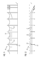
- FIG 1
- eine Seitenansicht einer Oberleitungsanlage des erfindungsgemäßen Transportsystems,
- FIG 2
- eine Draufsicht der Oberleitungsanlage nach
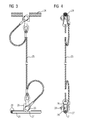
FIG 1 , - FIG 3
- eine Seitenansicht einer Hängerverbindung der Oberleitungsanlage nach
FIG 1 , - FIG 4
- eine Vorderansicht der Hängerverbindung nach
FIG 3 , - FIG 5
- ein erstes Ausführungsbeispiel eines Markierungselements des erfindungsgemäßen Transportsystems in perspektivischer Ansicht,
- FIG 6
- eine Seitenansicht des erfindungsgemäßen Transportsystems mit Markierungselementen nach
FIG 5 , - FIG 7
- ein zweites Ausführungsbeispiel eines Markierungselements des erfindungsgemäßen Transportsystems im Querschnitt,
- FIG 8
- eine Vorderansicht des erfindungsgemäßen Transportsystems mit Markierungselementen nach
FIG 7 , - FIG 9
- ein drittes Ausführungsbeispiel eines Markierungselements des erfindungsgemäßen Transportsystems in Seitenansicht,
- FIG 10
- eine Draufsicht des erfindungsgemäßen Transportsystems mit Markierungselementen nach
FIG 9 und - FIG 11
- eine Vorderansicht eines Videodetektors des Transportsystems nach
FIG 10
- FIG. 1
- a side view of a trolley system of the transport system according to the invention,
- FIG. 2
- a plan view of the overhead contact line after
FIG. 1 . - FIG. 3
- a side view of a trailer connection of the overhead contact line according to
FIG. 1 . - FIG. 4
- a front view of the trailer connection according to
FIG. 3 . - FIG. 5
- a first embodiment of a marking element of the transport system according to the invention in a perspective view,
- FIG. 6
- a side view of the transport system according to the invention with marking elements
FIG. 5 . - FIG. 7
- A second embodiment of a marking element of the transport system according to the invention in cross section,
- FIG. 8
- a front view of the transport system according to the invention with marking elements after
FIG. 7 . - FIG. 9
- A third embodiment of a marking element of the transport system according to the invention in side view,
- FIG. 10
- a top view of the transport system according to the invention with marking elements
FIG. 9 and - FIG. 11
- a front view of a video detector of the transport system after
FIG. 10
Ein erfindungsgemäßes Transportsystem umfasst gemäß
Gemäß
Der Stromabnehmer 13 weist zwei Tragarme 14 auf, die eine Wippenanordnung 15 mit Schleifleisten 16 tragen. Die Tragarme 14 sind fahrzeugseitig um horizontale Achsen drehbar gelagert, wodurch die Wippenanordnung 15 mittels einer nicht dargestellten Hubeinrichtung zwischen einer unteren Ruheposition, in der der Stromabnehmer 13 über der Fahrerkabine 11 abgelegt ist, und einer oberen Arbeitsposition, in der die Schleifleisten 16 die Fahrdrähte 21 kontaktieren, anheb- und absenkbar ist. Ferner sind die Tragarme 14 fahrzeugseitig um vertikale Achsen drehbar gelagert, wodurch die Wippenanordnung 15 mittels nicht dargestellter Stellantriebe seitlich, also quer zu einer Fahrtrichtung V des Fahrzeugs 10, verschwenkbar ist. Hierdurch ist es möglich, die Wippenanordnung 15 bei seitlichen Fahrungenauigkeiten innerhalb der Fahrspur L derart nachzustellen, dass die Schleifleisten 16 den Schleifkontakt zu den Fahrdrähten 21 und damit die Energieeinspeisung aufrechterhalten. Hierzu ist eine nicht dargestellte Regeleinrichtung vorgesehen, die mit einem fahrzeugseitig angeordneten Videodetektor 17 zur Ermittlung einer seitlichen Relativlage der Fahrdrähte 21 relativ zum Fahrzeug 10 verbunden ist. Die Regeleinrichtung weist eine nicht dargestellte Steuereinheit auf, die aus der ermittelten Relativlage und der aktuellen Stellung der Wippenanordnung 15 eine Stellgröße für die Stellantriebe derart berechnet, dass die Schleifleisten 16 innerhalb ihres Arbeitsbereiches die Fahrdrähte 21 kontaktieren. Daher ist die Steuereinheit mit den Stellantrieben verbunden, um an diese ein der berechneten Stellgröße entsprechendes Steuersignal zu übertragen. Die Stellantriebe Verschwenken die Wippenanordnung 15 durch Drehung der Tragarme 14 um deren vertikale Achsen.The
Diese seitliche Nachführung des Stromabnehmers 13 erfordert eine verlässliche Ermittlung der Relativlage des Fahrzeugs 10 zu den Fahrdrähten 21. Es ist daher erfindungsgemäß vorgesehen, dass die Oberleitungsanlage 20 die Lage der Fahrdrähte 21 markierende Markierungselemente aufweist. Der Videodetektor 17 ist hierfür zur Aufnahme von Videobildern der Markierungselemente ausgerichtet. Dem Videodetektor 17 ist eine nicht dargestellte Auswertungseinheit zugeordnet, die dazu ausgebildet ist, aus einem aufgenommenen Videobild zu erkennen, ob Fahrdrähte 21 oberhalb des Fahrzeugs 10 vorhanden sind, und bei Vorhandensein von Fahrdrähten 21 deren Relativlage zum Fahrzeug 10 zu ermitteln. Die Auswertungseinheit kann beispielsweise im Videodetektor 17 integriert sein. Der Videodetektor 17 kann als Stereokamera zur Aufnahme von 3D-Bildern oder als Laufzeitkamera zur Abstandsmessung zwischen Videodetektor 17 und einem Markierungselement ausgebildet sein. Der Videodetektor 17 kann eine nicht dargestellte Belichtungseinheit aufweisen, die zur Aussendung von Infrarotlicht in Richtung einer Erfassungsachse 18 des Videodetektors 17 ausgebildet ist.This lateral tracking of the
In einem ersten Ausführungsbeispiel des erfindungsgemäßen Transportsystems gemäß
In einem zweiten Ausführungsbeispiel des erfindungsgemäßen Transportsystems gemäß
In einem dritten Ausführungsbeispiel des erfindungsgemäßen Transportsystems gemäß
In allen Ausführungsbeispielen, die auch untereinander kombinierbar sind, wird anhand der auf den aufgenommenen Videobildern gut erkennbaren Markierungselemente direkt oder indirekt ermittelt, ob überhaupt ein Fahrdraht 21 im Umfeld des Fahrzeugs 10 vorhanden ist, ob die richtige Anzahl an Fahrdrähten 21 vorhanden ist, welchen Abstand diese zueinander und von der Oberfläche der Fahrspur L haben, und welchen seitlichen Versatz diese von einer Fahrspurlängsmitte haben. Daraus kann - gegebenenfalls mit Zusatzinformationen über Mastpositionen und Entfernungen zum Mast - die Auswertungseinheit die aktuelle Relativlage des Fahrzeugs 10 zu den Fahrdrähten 21 berechnen. Hierbei ist auch bei schlechten Wetterverhältnissen die Verwendung günstiger Stereo- oder Laufzeitkameras als Videodetektoren 17 möglich. Die mit der Auswertungseinheit gekoppelte Steuereinrichtung des Stromabnehmers 13 steuert die Hubeinrichtung zum Anheben der Wippenanordnung 15 an, wenn die Auswertungseinheit das Vorhandensein der richtigen Oberleitung festgestellt hat. Sie steuert die Stellantriebe zum seitlichen Verschwenken der Wippenanordnung 15 an, wenn die Auswertungseinheit eine Relativlage zwischen Fahrzeug 10 und Fahrdrähten 21 festgestellt hat, die zu einem drohenden Kontaktverlust der Schleifleisten 16 zu den Fahrdrähten führen könnte. Ist der drohende Kontaktverlust nicht mehr durch ein seitliches Nachführen des Stromabnehmers 13 vermeidbar, so steuert die Steuereinrichtung die Hubeinrichtung zum Absenken der Wippenanordnung 15 an.In all embodiments, which are also combinable with each other, is determined directly or indirectly based on the well-recorded on the video images marking elements, whether a
Claims (14)
Applications Claiming Priority (1)
| Application Number | Priority Date | Filing Date | Title |
|---|---|---|---|
| DE102014219466.0A DE102014219466A1 (en) | 2014-09-25 | 2014-09-25 | Transport system with a non-rail-bound vehicle that can be supplied with electrical energy via a trolley system |
Publications (2)
| Publication Number | Publication Date |
|---|---|
| EP3000644A1 true EP3000644A1 (en) | 2016-03-30 |
| EP3000644B1 EP3000644B1 (en) | 2020-06-03 |
Family
ID=54147043
Family Applications (1)
| Application Number | Title | Priority Date | Filing Date |
|---|---|---|---|
| EP15185210.0A Active EP3000644B1 (en) | 2014-09-25 | 2015-09-15 | Transport system with a vehicle which can be fed from an overhead electric installation and is not rail-bound |
Country Status (3)
| Country | Link |
|---|---|
| US (1) | US10023074B2 (en) |
| EP (1) | EP3000644B1 (en) |
| DE (1) | DE102014219466A1 (en) |
Cited By (1)
| Publication number | Priority date | Publication date | Assignee | Title |
|---|---|---|---|---|
| WO2021189086A1 (en) * | 2020-03-19 | 2021-09-23 | Transnet Soc Ltd | Visual indicator device, system for monitoring the visual indicator device and method thereof |
Families Citing this family (15)
| Publication number | Priority date | Publication date | Assignee | Title |
|---|---|---|---|---|
| US9283866B2 (en) * | 2012-01-31 | 2016-03-15 | Joy MM Deleware, Inc. | Overhead power grid for mobile mining machines |
| US11163313B2 (en) * | 2015-12-18 | 2021-11-02 | Volvo Truck Corporation | Methods for positioning vehicles using electric road systems and vehicles operated using these methods |
| DE102016205804A1 (en) | 2016-04-07 | 2017-10-12 | Siemens Aktiengesellschaft | Positioning System |
| ITUA20162698A1 (en) * | 2016-04-19 | 2017-10-19 | Mer Mec S P A | OPTICAL SYSTEM FOR THE MEASUREMENT OF THE CONTACT FORCE BETWEEN THE PANTOGRAPH AND THE CATENARY |
| DE102016013065B4 (en) * | 2016-11-03 | 2022-07-28 | Henryk Bastian | Additional current collectors for rail vehicles with current collection via an overhead line |
| CN108773272A (en) * | 2018-04-11 | 2018-11-09 | 徐州市彭宁机电科技有限公司 | Connecting rod surmounts device |
| SE1950714A1 (en) * | 2019-06-13 | 2020-09-29 | Elonroad Ab | Method, control circuit and control system for guiding a sliding contact of a vehicle to collect electrical power |
| DE102019130349A1 (en) * | 2019-11-11 | 2021-05-12 | Kiepe Electric Gmbh | Pantograph system and method for automatically connecting and / or disconnecting a pantograph system |
| CN111017247A (en) * | 2019-12-13 | 2020-04-17 | 北京京东乾石科技有限公司 | Pantograph, power supply system and distribution system |
| DE102020204566A1 (en) | 2020-04-08 | 2021-10-14 | Volkswagen Aktiengesellschaft | Coupling method for coupling a vehicle with an overhead line, computer program product and vehicle |
| CN112297957B (en) * | 2020-09-08 | 2021-12-14 | 北京京东乾石科技有限公司 | Wiping line detection device and wiping line detection system |
| DE202022102525U1 (en) | 2022-05-09 | 2023-08-10 | Hofer Powertrain Innovation Gmbh | Power supply system for motor vehicles, especially commercial vehicles for electrically powered heavy traffic |
| CN114734883B (en) * | 2022-03-23 | 2023-07-04 | 中铁建电气化局集团第一工程有限公司 | Intelligent installation system for overhead contact system hanger |
| WO2024002563A1 (en) * | 2022-06-30 | 2024-01-04 | Siemens Mobility GmbH | Energy supply system for feeding energy into a road vehicle |
| DE102022208846A1 (en) * | 2022-08-26 | 2024-02-29 | Siemens Mobility GmbH | Road vehicle with a pantograph |
Citations (9)
| Publication number | Priority date | Publication date | Assignee | Title |
|---|---|---|---|---|
| US4070584A (en) * | 1974-12-20 | 1978-01-24 | Thomson-Csf | Object-identification system with sequentially activated photocell array |
| FR2540801A1 (en) | 1983-02-15 | 1984-08-17 | Techno 2000 | Device for hooking up a trolley bus with at least one catenary |
| GB2244581A (en) | 1990-06-02 | 1991-12-04 | Solvit Scient Engineers Limite | System to read barcode signs from or on a moving vehicle |
| DE102010053528A1 (en) | 2010-11-30 | 2012-05-31 | Dialogika Gesellschaft Für Angewandte Informatik Mbh | System for the automatic connection and disconnection during the journey of a trolley vehicle |
| DE102011076623A1 (en) | 2011-05-27 | 2012-11-29 | Siemens Ag | Non-rail vehicle |
| DE102011076620A1 (en) * | 2011-05-27 | 2012-11-29 | Siemens Aktiengesellschaft | Non-rail vehicle |
| DE102012205276A1 (en) | 2012-03-30 | 2013-10-02 | Siemens Aktiengesellschaft | Non-rail vehicle |
| DE102012213460A1 (en) * | 2012-07-31 | 2014-02-06 | Siemens Aktiengesellschaft | Non-rail-bound vehicle e.g. truck, has adjusting platform that is moveable transverse to vehicle longitudinal axis directed actuating movement of current collector in relative to vehicle by adjusting device |
| DE112012004019T5 (en) * | 2011-09-27 | 2014-07-17 | Hitachi Construction Machinery Co., Ltd. | Electrically powered dump truck |
Family Cites Families (2)
| Publication number | Priority date | Publication date | Assignee | Title |
|---|---|---|---|---|
| JP2005094952A (en) * | 2003-09-18 | 2005-04-07 | Akira Nomura | Current collector |
| DE102012210519A1 (en) * | 2012-06-21 | 2013-12-24 | Siemens Aktiengesellschaft | Vehicle with a driver-controlled and electronically controlled vehicle device |
-
2014
- 2014-09-25 DE DE102014219466.0A patent/DE102014219466A1/en not_active Ceased
-
2015
- 2015-09-15 EP EP15185210.0A patent/EP3000644B1/en active Active
- 2015-09-25 US US14/865,218 patent/US10023074B2/en active Active
Patent Citations (9)
| Publication number | Priority date | Publication date | Assignee | Title |
|---|---|---|---|---|
| US4070584A (en) * | 1974-12-20 | 1978-01-24 | Thomson-Csf | Object-identification system with sequentially activated photocell array |
| FR2540801A1 (en) | 1983-02-15 | 1984-08-17 | Techno 2000 | Device for hooking up a trolley bus with at least one catenary |
| GB2244581A (en) | 1990-06-02 | 1991-12-04 | Solvit Scient Engineers Limite | System to read barcode signs from or on a moving vehicle |
| DE102010053528A1 (en) | 2010-11-30 | 2012-05-31 | Dialogika Gesellschaft Für Angewandte Informatik Mbh | System for the automatic connection and disconnection during the journey of a trolley vehicle |
| DE102011076623A1 (en) | 2011-05-27 | 2012-11-29 | Siemens Ag | Non-rail vehicle |
| DE102011076620A1 (en) * | 2011-05-27 | 2012-11-29 | Siemens Aktiengesellschaft | Non-rail vehicle |
| DE112012004019T5 (en) * | 2011-09-27 | 2014-07-17 | Hitachi Construction Machinery Co., Ltd. | Electrically powered dump truck |
| DE102012205276A1 (en) | 2012-03-30 | 2013-10-02 | Siemens Aktiengesellschaft | Non-rail vehicle |
| DE102012213460A1 (en) * | 2012-07-31 | 2014-02-06 | Siemens Aktiengesellschaft | Non-rail-bound vehicle e.g. truck, has adjusting platform that is moveable transverse to vehicle longitudinal axis directed actuating movement of current collector in relative to vehicle by adjusting device |
Cited By (1)
| Publication number | Priority date | Publication date | Assignee | Title |
|---|---|---|---|---|
| WO2021189086A1 (en) * | 2020-03-19 | 2021-09-23 | Transnet Soc Ltd | Visual indicator device, system for monitoring the visual indicator device and method thereof |
Also Published As
| Publication number | Publication date |
|---|---|
| EP3000644B1 (en) | 2020-06-03 |
| DE102014219466A1 (en) | 2016-03-31 |
| US20160090007A1 (en) | 2016-03-31 |
| US10023074B2 (en) | 2018-07-17 |
Similar Documents
| Publication | Publication Date | Title |
|---|---|---|
| EP3000644B1 (en) | Transport system with a vehicle which can be fed from an overhead electric installation and is not rail-bound | |
| EP2714457B1 (en) | Non-rail-bound vehicle | |
| EP2644432B1 (en) | Vehicle that is not bound to rails | |
| DE60123936T2 (en) | DEVICE FOR RECOGNIZING THE PRESENCE OF OBJECTS | |
| EP3266638A1 (en) | Automated control of a target lane for the continuous supply with electric energy | |
| EP2701940A2 (en) | Non-railbound vehicle | |
| DE102011076620A1 (en) | Non-rail vehicle | |
| DE102009013841A1 (en) | Measuring system for traffic flow analysis | |
| DE102012213460A1 (en) | Non-rail-bound vehicle e.g. truck, has adjusting platform that is moveable transverse to vehicle longitudinal axis directed actuating movement of current collector in relative to vehicle by adjusting device | |
| EP2804014B1 (en) | Device and method for determining a characteristic of a vehicle | |
| EP3264213B1 (en) | Motor vehicle, system and method for operating such a motor vehicle and such a system | |
| DE102007043460B4 (en) | Method for navigating a vehicle | |
| EP3109086A1 (en) | Transport system | |
| DE19940350C2 (en) | Method and arrangement for monitoring the contact wire of a route for electrically drivable rail vehicles | |
| DE102015213071A1 (en) | Infrastructure-based detection of overhead lines | |
| EP4063171A1 (en) | Current collector and a road vehicle comprising such a current collector | |
| DE102017213282A1 (en) | Method and detection system for checking a position of an electric motor driven motor vehicle | |
| DE102007063490A1 (en) | Measuring instrument for determining thickness of trolley wire for e.g. electrically operated railway, has cameras capturing and feeding optical information to evaluating device, and projectors projecting optical lines on sides of wire | |
| DE102009018763A1 (en) | Method for detecting components in overhead line installations of rail vehicles, in particular railway vehicles | |
| DE102017215226B4 (en) | Method for navigating a road-bound motor vehicle with a pantograph | |
| DE3207092A1 (en) | Positioning device for a rail-borne vehicle, preferably a crane | |
| EP1916642A1 (en) | Traffic detecting device | |
| CN220220612U (en) | AGV carrier | |
| EP2827047B1 (en) | Illumination device for marking a lane of a roadway | |
| EP4269169A1 (en) | Method for detecting the state of a roadside overhead line system |
Legal Events
| Date | Code | Title | Description |
|---|---|---|---|
| PUAI | Public reference made under article 153(3) epc to a published international application that has entered the european phase |
Free format text: ORIGINAL CODE: 0009012 |
|
| AK | Designated contracting states |
Kind code of ref document: A1 Designated state(s): AL AT BE BG CH CY CZ DE DK EE ES FI FR GB GR HR HU IE IS IT LI LT LU LV MC MK MT NL NO PL PT RO RS SE SI SK SM TR |
|
| AX | Request for extension of the european patent |
Extension state: BA ME |
|
| STAA | Information on the status of an ep patent application or granted ep patent |
Free format text: STATUS: THE APPLICATION HAS BEEN PUBLISHED |
|
| STAA | Information on the status of an ep patent application or granted ep patent |
Free format text: STATUS: REQUEST FOR EXAMINATION WAS MADE |
|
| 17P | Request for examination filed |
Effective date: 20170117 |
|
| RBV | Designated contracting states (corrected) |
Designated state(s): AL AT BE BG CH CY CZ DE DK EE ES FI FR GB GR HR HU IE IS IT LI LT LU LV MC MK MT NL NO PL PT RO RS SE SI SK SM TR |
|
| RAP1 | Party data changed (applicant data changed or rights of an application transferred) |
Owner name: SIEMENS AKTIENGESELLSCHAFT |
|
| STAA | Information on the status of an ep patent application or granted ep patent |
Free format text: STATUS: EXAMINATION IS IN PROGRESS |
|
| 17Q | First examination report despatched |
Effective date: 20180919 |
|
| RAP1 | Party data changed (applicant data changed or rights of an application transferred) |
Owner name: SIEMENS MOBILITY GMBH |
|
| REG | Reference to a national code |
Ref country code: DE Ref legal event code: R079 Ref document number: 502015012692 Country of ref document: DE Free format text: PREVIOUS MAIN CLASS: B60L0005040000 Ipc: B60M0001230000 |
|
| GRAP | Despatch of communication of intention to grant a patent |
Free format text: ORIGINAL CODE: EPIDOSNIGR1 |
|
| STAA | Information on the status of an ep patent application or granted ep patent |
Free format text: STATUS: GRANT OF PATENT IS INTENDED |
|
| RIC1 | Information provided on ipc code assigned before grant |
Ipc: B60M 1/12 20060101ALI20200115BHEP Ipc: B60L 5/36 20060101ALI20200115BHEP Ipc: B60L 5/04 20060101ALI20200115BHEP Ipc: B60M 1/23 20060101AFI20200115BHEP |
|
| INTG | Intention to grant announced |
Effective date: 20200205 |
|
| GRAS | Grant fee paid |
Free format text: ORIGINAL CODE: EPIDOSNIGR3 |
|
| GRAA | (expected) grant |
Free format text: ORIGINAL CODE: 0009210 |
|
| STAA | Information on the status of an ep patent application or granted ep patent |
Free format text: STATUS: THE PATENT HAS BEEN GRANTED |
|
| AK | Designated contracting states |
Kind code of ref document: B1 Designated state(s): AL AT BE BG CH CY CZ DE DK EE ES FI FR GB GR HR HU IE IS IT LI LT LU LV MC MK MT NL NO PL PT RO RS SE SI SK SM TR |
|
| REG | Reference to a national code |
Ref country code: GB Ref legal event code: FG4D Free format text: NOT ENGLISH |
|
| REG | Reference to a national code |
Ref country code: CH Ref legal event code: EP Ref country code: AT Ref legal event code: REF Ref document number: 1276688 Country of ref document: AT Kind code of ref document: T Effective date: 20200615 |
|
| REG | Reference to a national code |
Ref country code: DE Ref legal event code: R096 Ref document number: 502015012692 Country of ref document: DE |
|
| REG | Reference to a national code |
Ref country code: LT Ref legal event code: MG4D |
|
| PG25 | Lapsed in a contracting state [announced via postgrant information from national office to epo] |
Ref country code: SE Free format text: LAPSE BECAUSE OF FAILURE TO SUBMIT A TRANSLATION OF THE DESCRIPTION OR TO PAY THE FEE WITHIN THE PRESCRIBED TIME-LIMIT Effective date: 20200603 Ref country code: GR Free format text: LAPSE BECAUSE OF FAILURE TO SUBMIT A TRANSLATION OF THE DESCRIPTION OR TO PAY THE FEE WITHIN THE PRESCRIBED TIME-LIMIT Effective date: 20200904 Ref country code: NO Free format text: LAPSE BECAUSE OF FAILURE TO SUBMIT A TRANSLATION OF THE DESCRIPTION OR TO PAY THE FEE WITHIN THE PRESCRIBED TIME-LIMIT Effective date: 20200903 Ref country code: FI Free format text: LAPSE BECAUSE OF FAILURE TO SUBMIT A TRANSLATION OF THE DESCRIPTION OR TO PAY THE FEE WITHIN THE PRESCRIBED TIME-LIMIT Effective date: 20200603 Ref country code: LT Free format text: LAPSE BECAUSE OF FAILURE TO SUBMIT A TRANSLATION OF THE DESCRIPTION OR TO PAY THE FEE WITHIN THE PRESCRIBED TIME-LIMIT Effective date: 20200603 |
|
| REG | Reference to a national code |
Ref country code: NL Ref legal event code: MP Effective date: 20200603 |
|
| PG25 | Lapsed in a contracting state [announced via postgrant information from national office to epo] |
Ref country code: LV Free format text: LAPSE BECAUSE OF FAILURE TO SUBMIT A TRANSLATION OF THE DESCRIPTION OR TO PAY THE FEE WITHIN THE PRESCRIBED TIME-LIMIT Effective date: 20200603 Ref country code: BG Free format text: LAPSE BECAUSE OF FAILURE TO SUBMIT A TRANSLATION OF THE DESCRIPTION OR TO PAY THE FEE WITHIN THE PRESCRIBED TIME-LIMIT Effective date: 20200903 Ref country code: RS Free format text: LAPSE BECAUSE OF FAILURE TO SUBMIT A TRANSLATION OF THE DESCRIPTION OR TO PAY THE FEE WITHIN THE PRESCRIBED TIME-LIMIT Effective date: 20200603 Ref country code: HR Free format text: LAPSE BECAUSE OF FAILURE TO SUBMIT A TRANSLATION OF THE DESCRIPTION OR TO PAY THE FEE WITHIN THE PRESCRIBED TIME-LIMIT Effective date: 20200603 |
|
| PG25 | Lapsed in a contracting state [announced via postgrant information from national office to epo] |
Ref country code: NL Free format text: LAPSE BECAUSE OF FAILURE TO SUBMIT A TRANSLATION OF THE DESCRIPTION OR TO PAY THE FEE WITHIN THE PRESCRIBED TIME-LIMIT Effective date: 20200603 Ref country code: AL Free format text: LAPSE BECAUSE OF FAILURE TO SUBMIT A TRANSLATION OF THE DESCRIPTION OR TO PAY THE FEE WITHIN THE PRESCRIBED TIME-LIMIT Effective date: 20200603 |
|
| PG25 | Lapsed in a contracting state [announced via postgrant information from national office to epo] |
Ref country code: EE Free format text: LAPSE BECAUSE OF FAILURE TO SUBMIT A TRANSLATION OF THE DESCRIPTION OR TO PAY THE FEE WITHIN THE PRESCRIBED TIME-LIMIT Effective date: 20200603 Ref country code: IT Free format text: LAPSE BECAUSE OF FAILURE TO SUBMIT A TRANSLATION OF THE DESCRIPTION OR TO PAY THE FEE WITHIN THE PRESCRIBED TIME-LIMIT Effective date: 20200603 Ref country code: SM Free format text: LAPSE BECAUSE OF FAILURE TO SUBMIT A TRANSLATION OF THE DESCRIPTION OR TO PAY THE FEE WITHIN THE PRESCRIBED TIME-LIMIT Effective date: 20200603 Ref country code: PT Free format text: LAPSE BECAUSE OF FAILURE TO SUBMIT A TRANSLATION OF THE DESCRIPTION OR TO PAY THE FEE WITHIN THE PRESCRIBED TIME-LIMIT Effective date: 20201006 Ref country code: ES Free format text: LAPSE BECAUSE OF FAILURE TO SUBMIT A TRANSLATION OF THE DESCRIPTION OR TO PAY THE FEE WITHIN THE PRESCRIBED TIME-LIMIT Effective date: 20200603 Ref country code: CZ Free format text: LAPSE BECAUSE OF FAILURE TO SUBMIT A TRANSLATION OF THE DESCRIPTION OR TO PAY THE FEE WITHIN THE PRESCRIBED TIME-LIMIT Effective date: 20200603 Ref country code: RO Free format text: LAPSE BECAUSE OF FAILURE TO SUBMIT A TRANSLATION OF THE DESCRIPTION OR TO PAY THE FEE WITHIN THE PRESCRIBED TIME-LIMIT Effective date: 20200603 |
|
| PG25 | Lapsed in a contracting state [announced via postgrant information from national office to epo] |
Ref country code: PL Free format text: LAPSE BECAUSE OF FAILURE TO SUBMIT A TRANSLATION OF THE DESCRIPTION OR TO PAY THE FEE WITHIN THE PRESCRIBED TIME-LIMIT Effective date: 20200603 Ref country code: SK Free format text: LAPSE BECAUSE OF FAILURE TO SUBMIT A TRANSLATION OF THE DESCRIPTION OR TO PAY THE FEE WITHIN THE PRESCRIBED TIME-LIMIT Effective date: 20200603 Ref country code: IS Free format text: LAPSE BECAUSE OF FAILURE TO SUBMIT A TRANSLATION OF THE DESCRIPTION OR TO PAY THE FEE WITHIN THE PRESCRIBED TIME-LIMIT Effective date: 20201003 |
|
| REG | Reference to a national code |
Ref country code: DE Ref legal event code: R097 Ref document number: 502015012692 Country of ref document: DE |
|
| PLBE | No opposition filed within time limit |
Free format text: ORIGINAL CODE: 0009261 |
|
| STAA | Information on the status of an ep patent application or granted ep patent |
Free format text: STATUS: NO OPPOSITION FILED WITHIN TIME LIMIT |
|
| PG25 | Lapsed in a contracting state [announced via postgrant information from national office to epo] |
Ref country code: DK Free format text: LAPSE BECAUSE OF FAILURE TO SUBMIT A TRANSLATION OF THE DESCRIPTION OR TO PAY THE FEE WITHIN THE PRESCRIBED TIME-LIMIT Effective date: 20200603 Ref country code: MC Free format text: LAPSE BECAUSE OF FAILURE TO SUBMIT A TRANSLATION OF THE DESCRIPTION OR TO PAY THE FEE WITHIN THE PRESCRIBED TIME-LIMIT Effective date: 20200603 |
|
| REG | Reference to a national code |
Ref country code: CH Ref legal event code: PL |
|
| 26N | No opposition filed |
Effective date: 20210304 |
|
| GBPC | Gb: european patent ceased through non-payment of renewal fee |
Effective date: 20200915 |
|
| PG25 | Lapsed in a contracting state [announced via postgrant information from national office to epo] |
Ref country code: SI Free format text: LAPSE BECAUSE OF FAILURE TO SUBMIT A TRANSLATION OF THE DESCRIPTION OR TO PAY THE FEE WITHIN THE PRESCRIBED TIME-LIMIT Effective date: 20200603 |
|
| REG | Reference to a national code |
Ref country code: BE Ref legal event code: MM Effective date: 20200930 |
|
| PG25 | Lapsed in a contracting state [announced via postgrant information from national office to epo] |
Ref country code: LU Free format text: LAPSE BECAUSE OF NON-PAYMENT OF DUE FEES Effective date: 20200915 |
|
| PG25 | Lapsed in a contracting state [announced via postgrant information from national office to epo] |
Ref country code: FR Free format text: LAPSE BECAUSE OF NON-PAYMENT OF DUE FEES Effective date: 20200930 |
|
| PG25 | Lapsed in a contracting state [announced via postgrant information from national office to epo] |
Ref country code: CH Free format text: LAPSE BECAUSE OF NON-PAYMENT OF DUE FEES Effective date: 20200930 Ref country code: BE Free format text: LAPSE BECAUSE OF NON-PAYMENT OF DUE FEES Effective date: 20200930 Ref country code: GB Free format text: LAPSE BECAUSE OF NON-PAYMENT OF DUE FEES Effective date: 20200915 Ref country code: LI Free format text: LAPSE BECAUSE OF NON-PAYMENT OF DUE FEES Effective date: 20200930 Ref country code: IE Free format text: LAPSE BECAUSE OF NON-PAYMENT OF DUE FEES Effective date: 20200915 |
|
| REG | Reference to a national code |
Ref country code: AT Ref legal event code: MM01 Ref document number: 1276688 Country of ref document: AT Kind code of ref document: T Effective date: 20200915 |
|
| PG25 | Lapsed in a contracting state [announced via postgrant information from national office to epo] |
Ref country code: AT Free format text: LAPSE BECAUSE OF NON-PAYMENT OF DUE FEES Effective date: 20200915 |
|
| PG25 | Lapsed in a contracting state [announced via postgrant information from national office to epo] |
Ref country code: TR Free format text: LAPSE BECAUSE OF FAILURE TO SUBMIT A TRANSLATION OF THE DESCRIPTION OR TO PAY THE FEE WITHIN THE PRESCRIBED TIME-LIMIT Effective date: 20200603 Ref country code: MT Free format text: LAPSE BECAUSE OF FAILURE TO SUBMIT A TRANSLATION OF THE DESCRIPTION OR TO PAY THE FEE WITHIN THE PRESCRIBED TIME-LIMIT Effective date: 20200603 Ref country code: CY Free format text: LAPSE BECAUSE OF FAILURE TO SUBMIT A TRANSLATION OF THE DESCRIPTION OR TO PAY THE FEE WITHIN THE PRESCRIBED TIME-LIMIT Effective date: 20200603 |
|
| PG25 | Lapsed in a contracting state [announced via postgrant information from national office to epo] |
Ref country code: MK Free format text: LAPSE BECAUSE OF FAILURE TO SUBMIT A TRANSLATION OF THE DESCRIPTION OR TO PAY THE FEE WITHIN THE PRESCRIBED TIME-LIMIT Effective date: 20200603 |
|
| PGFP | Annual fee paid to national office [announced via postgrant information from national office to epo] |
Ref country code: DE Payment date: 20231120 Year of fee payment: 9 |