EP3020660A1 - Device and method for determining a content level of a transport device - Google Patents
Device and method for determining a content level of a transport device Download PDFInfo
- Publication number
- EP3020660A1 EP3020660A1 EP15187291.8A EP15187291A EP3020660A1 EP 3020660 A1 EP3020660 A1 EP 3020660A1 EP 15187291 A EP15187291 A EP 15187291A EP 3020660 A1 EP3020660 A1 EP 3020660A1
- Authority
- EP
- European Patent Office
- Prior art keywords
- detection
- transport
- transport device
- determining
- transported
- Prior art date
- Legal status (The legal status is an assumption and is not a legal conclusion. Google has not performed a legal analysis and makes no representation as to the accuracy of the status listed.)
- Granted
Links
- 238000000034 method Methods 0.000 title claims abstract description 18
- 238000001514 detection method Methods 0.000 claims abstract description 142
- 230000032258 transport Effects 0.000 description 109
- 238000005259 measurement Methods 0.000 description 4
- 230000003287 optical effect Effects 0.000 description 4
- 238000002372 labelling Methods 0.000 description 3
- 230000008901 benefit Effects 0.000 description 2
- 235000013361 beverage Nutrition 0.000 description 2
- 238000012544 monitoring process Methods 0.000 description 2
- 230000005693 optoelectronics Effects 0.000 description 2
- 238000007792 addition Methods 0.000 description 1
- 230000008859 change Effects 0.000 description 1
- 238000004140 cleaning Methods 0.000 description 1
- 239000012459 cleaning agent Substances 0.000 description 1
- 230000001419 dependent effect Effects 0.000 description 1
- 238000013461 design Methods 0.000 description 1
- 238000010586 diagram Methods 0.000 description 1
- 238000009826 distribution Methods 0.000 description 1
- 239000011521 glass Substances 0.000 description 1
- 239000007788 liquid Substances 0.000 description 1
- 238000004519 manufacturing process Methods 0.000 description 1
- 239000000463 material Substances 0.000 description 1
- 239000002184 metal Substances 0.000 description 1
- 238000012986 modification Methods 0.000 description 1
- 230000004048 modification Effects 0.000 description 1
- 238000005457 optimization Methods 0.000 description 1
- 238000004806 packaging method and process Methods 0.000 description 1
- 229920003023 plastic Polymers 0.000 description 1
- 239000000843 powder Substances 0.000 description 1
- 238000012545 processing Methods 0.000 description 1
- 238000002604 ultrasonography Methods 0.000 description 1
- 238000011144 upstream manufacturing Methods 0.000 description 1
Images


Classifications
-
- G—PHYSICS
- G06—COMPUTING; CALCULATING OR COUNTING
- G06M—COUNTING MECHANISMS; COUNTING OF OBJECTS NOT OTHERWISE PROVIDED FOR
- G06M7/00—Counting of objects carried by a conveyor
-
- B—PERFORMING OPERATIONS; TRANSPORTING
- B65—CONVEYING; PACKING; STORING; HANDLING THIN OR FILAMENTARY MATERIAL
- B65G—TRANSPORT OR STORAGE DEVICES, e.g. CONVEYORS FOR LOADING OR TIPPING, SHOP CONVEYOR SYSTEMS OR PNEUMATIC TUBE CONVEYORS
- B65G43/00—Control devices, e.g. for safety, warning or fault-correcting
- B65G43/08—Control devices operated by article or material being fed, conveyed or discharged
-
- B—PERFORMING OPERATIONS; TRANSPORTING
- B65—CONVEYING; PACKING; STORING; HANDLING THIN OR FILAMENTARY MATERIAL
- B65G—TRANSPORT OR STORAGE DEVICES, e.g. CONVEYORS FOR LOADING OR TIPPING, SHOP CONVEYOR SYSTEMS OR PNEUMATIC TUBE CONVEYORS
- B65G15/00—Conveyors having endless load-conveying surfaces, i.e. belts and like continuous members, to which tractive effort is transmitted by means other than endless driving elements of similar configuration
- B65G15/22—Conveyors having endless load-conveying surfaces, i.e. belts and like continuous members, to which tractive effort is transmitted by means other than endless driving elements of similar configuration comprising a series of co-operating units
-
- G—PHYSICS
- G06—COMPUTING; CALCULATING OR COUNTING
- G06M—COUNTING MECHANISMS; COUNTING OF OBJECTS NOT OTHERWISE PROVIDED FOR
- G06M1/00—Design features of general application
- G06M1/02—Housing
-
- B—PERFORMING OPERATIONS; TRANSPORTING
- B65—CONVEYING; PACKING; STORING; HANDLING THIN OR FILAMENTARY MATERIAL
- B65G—TRANSPORT OR STORAGE DEVICES, e.g. CONVEYORS FOR LOADING OR TIPPING, SHOP CONVEYOR SYSTEMS OR PNEUMATIC TUBE CONVEYORS
- B65G2201/00—Indexing codes relating to handling devices, e.g. conveyors, characterised by the type of product or load being conveyed or handled
- B65G2201/02—Articles
- B65G2201/0235—Containers
- B65G2201/0244—Bottles
-
- B—PERFORMING OPERATIONS; TRANSPORTING
- B65—CONVEYING; PACKING; STORING; HANDLING THIN OR FILAMENTARY MATERIAL
- B65G—TRANSPORT OR STORAGE DEVICES, e.g. CONVEYORS FOR LOADING OR TIPPING, SHOP CONVEYOR SYSTEMS OR PNEUMATIC TUBE CONVEYORS
- B65G2203/00—Indexing code relating to control or detection of the articles or the load carriers during conveying
- B65G2203/02—Control or detection
- B65G2203/0208—Control or detection relating to the transported articles
-
- B—PERFORMING OPERATIONS; TRANSPORTING
- B65—CONVEYING; PACKING; STORING; HANDLING THIN OR FILAMENTARY MATERIAL
- B65G—TRANSPORT OR STORAGE DEVICES, e.g. CONVEYORS FOR LOADING OR TIPPING, SHOP CONVEYOR SYSTEMS OR PNEUMATIC TUBE CONVEYORS
- B65G2203/00—Indexing code relating to control or detection of the articles or the load carriers during conveying
- B65G2203/04—Detection means
- B65G2203/042—Sensors
- B65G2203/044—Optical
Definitions
- the present invention relates to an apparatus and a method for determining a degree of occupancy of a transport device, which in particular transports containers in a container treatment plant.
- a plurality of containers can be transported side by side in a transport direction.
- the transport device is fully or even partially occupied by containers. It is advantageous to reduce the speed of downstream devices, such. B. cleaning device, packaging device, etc. depending on the occupancy rate of the transport device to regulate.
- an automatic control and regulation of the container treatment plant can be realized with the least possible use of operating personnel.
- WO 2008/116546 A2 shows a method for monitoring, control and optimization of filling equipment for food, especially for beverage bottles.
- the procedure is used for plant or machine monitoring.
- an optoelectronic recognition system in the form of at least one electronic camera is used in order to obtain the necessary control data.
- the optical Detection systems can be used to monitor the occupancy rate of buffer tables.
- a disadvantage of such optical recognition systems is that the camera systems reach their limits when processing non-cooperative container surfaces. In this case, a stable detection of the occupancy rate is not guaranteed.
- an object of the present invention to provide an apparatus and a method for determining a degree of occupancy of a transport device, with which the aforementioned problems can be solved.
- an apparatus and a method for determining a degree of occupancy of a transport device are to be provided, with which a determination of a degree of occupancy of a transport device can be implemented simply, flexibly and cost-effectively.
- the device comprises an adjusting device for setting at least one detection device such that the at least one detection device detects the transport device without transported transported goods after detecting transported goods transported with the transport device or vice versa, and a determination device for determining a current degree of occupancy of the transport device on the basis of the adjustment set position of the at least one detection device.
- the device comprises only simple, process-stable standard components. Therefore, no expert knowledge or special software for setting the device is required.
- the device does not require smart detectors such as light-section based sensors or camera or laser technology. Thus, the hardware required for the device is reduced.
- the aforementioned device offers a very efficient and cost-effective way of detecting or determining the occupancy rate. This results in only a very low calibration and referencing.
- the device due to their simple design substantially independent of the width of the conveyor belt to be detected.
- the setting device is also possible for setting at least two detection devices such that a detection device of the detection devices detects transported goods transported by the transport device and the other detection device of the detection devices detects the transport device without transported transported goods, and wherein the determination device determines the current occupancy rate of the transport device Transport device determined on the basis of the set by the setting position of at least one of the detection devices.
- the at least two detection devices are designed to detect transversely to the transport plane of the transport device.
- the device also has a support device for supporting the at least one detection device and / or for supporting at least two detection devices such that the at least two detection devices are arranged at a predetermined fixed distance from one another.
- the support device can be designed to arrange the at least one detection device over the transport device.
- the support means may comprise a receiving device for receiving the at least one detection device, which is designed as a carriage or pull rope such that the at least one detection device is linearly movable over the transport device.
- the device also has a position detection device for detecting a position of the at least one detection device and / or a receiving device receiving the at least one detection device on the support device.
- a position detection device for detecting a position of the at least one detection device and / or a receiving device receiving the at least one detection device on the support device.
- the at least one detection device comprises a contactless sensor.
- the device described above may be part of a transport device for transporting containers, wherein the transport device also has a conveyor belt for transporting the containers in a predetermined transport direction.
- the transport device additionally has at least one further conveyor belt, which can be driven independently of the conveyor belt at different speeds to the conveyor belt.
- the object is also achieved by a method for determining a degree of occupancy of a transport device according to claim 10.
- the method comprises the steps of adjusting, with an adjustment device, at least one detection device such that the at least one detection device detects the transport device without transported transported goods after detecting transported goods transported with the transport device, and vice versa, and determining, with a determination device, a current occupancy level the transport device on the Basis of the adjustment of the set position of the at least one detection device.
- the method achieves the same advantages as previously mentioned with respect to the device.
- Fig. 1 shows a machine 1, which may be, for example, a container treatment plant.
- containers 2 in particular transparent plastic bottles, glass bottles, metal cans, empty, full, closed, unsealed, labeled, not labeled, etc., are produced and / or treated.
- the machine 1 is described below partially using the example of a container treatment plant, the machine 1 is not limited thereto.
- Fig. 1 For the sake of simplicity, not all containers 2 are provided with a reference numeral.
- the machine 1 has a first treatment device 10, a transport device 20 and a second treatment device 30.
- the first treatment device 10 is, for example, a labeling device for labeling containers 2 with a label.
- the second treatment device 30 is, for example, a filling device for filling the containers 2 with a medium, such as a liquid, a powder, etc., in particular a beverage, a cleaning agent, etc.
- the transport device 20 transports the containers 2 as transported goods from the first Treatment device 10 to the second treatment device 30th
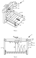
- Fig. 2 shows a part of the transport device 20 in more detail.
- the transport device 20 has a conveyor belt 21 for transporting goods to be transported, such as the container 2, in a transport direction TR.
- the transport device 20 In Fig. 2 is the conveyor belt 21 and thus the transport device 20 only partially occupied by cargo in the form of the container 2.
- the other part of the conveyor belt 21 is free of cargo in the form of containers 2.
- the occupancy rate of the transport device 20 is about 35%. Accordingly, in about 65% of the transport device 20 are not occupied by cargo in the form of container 2.
- a device 23 for determining a degree of occupancy of the transport device 20 is mounted on the transport device 20.
- the device 23 has a support device 24, a receiving unit 241, a drive device 242, a first detection device 25, a second detection device 26, a position detection device 27, an adjustment device 28 and a detection device 29.
- the reception unit 241 is connected to the drive device 242 in a movement direction BR movable.
- the adjusting device 28 is combined with the drive device 242 or controls these.
- a part of the support means 24 is arranged together with the receiving unit 241 and the first and second detection means 25, 26 above the transport means 20. More specifically, the receiving unit 241 and the first and second detecting means 25, 26 are disposed above the conveyor belt 21.
- the support means 24 is configured as a U-shaped frame to which the receiving unit 241 is attached.
- the first and second detection means 25, 26 are accommodated on the receiving unit 241 in such a way that the first and second detection means 25, 26 are spaced from each other by the fixed predetermined distance AB, as in FIG Fig. 4 shown.
- the support means 24 supports the first detection means 25 at the predetermined fixed distance AB to the second detection means 26th
- the receiving unit 241 is movably mounted on the support means 24. Thereby, the receiving unit 241 can be moved together with the first and second detection means 25, 26 as a unit relative to the support means 24 in the direction of the arrow designated BR.
- the arrow thus indicates the direction of movement BR of the receiving unit 241 and the first and second detecting means 25, 26.
- the receiving unit 241 is shown as a carriage on which the first and second detecting means 25, 26 are mounted.
- the carriage can be driven by the drive device 242, which is in particular an electric motor.
- the receiving unit 241 and the detection means 25, 26 are set in a common linear movement via the transport device 20.
- the receiving unit 241 can be reciprocated together with the first and second detecting means 25, 26 via the transporting means 20 in the moving direction BR.
- the first and second detection means 26, 27 can be moved transversely to the transport direction TR relative to the transport means 20.
- the direction of movement BR of the receiving unit 241 and the first and second detection means 25, 26 is arranged transversely, in particular perpendicular, to the transport direction TR of the conveyor belt 21.
- the term "transverse" here comprises an angle between 1 ° and 90 ° to the transport direction TR.
- the device 23 can also be used, for example, on a push-over, at which the containers 2 are forwarded by the conveyor belt 21 to a laterally arranged next conveyor belt 21.
- the device 23 could then be mounted in a different arrangement than at right angles to the transport direction TR.
- the support device 24 is thus designed for the movable supports of the first and second detection means 25, 26, so that the first and second detection means 25, 26 are movable together in a linear manner over the transport means 20.
- the first and second detection means 25, 26 are each in particular non-contact and / or momentary sensors, such as an optical sensor, which operates by means of light, such as infrared light, laser light, etc.
- each of the first and second detection means 25, 26 can also be an acoustic sensor which operates by means of sound waves, preferably ultrasound.
- the first and second detection means 25, 26 can each also be a capacitive sensor.
- the first and second detection means 25, 26 can be configured such that the respective detection means 25, 26 have both a transmitter for transmitting the detection waves and a receiver for receiving the detection waves. As in FIG. 3 and FIG. 4 1, the detection waves are returned to the detectors 25, 26 in the direction of an arrow labeled MS by the conveyor 20 or the cargo.
- first and second detection means 25, 26 are thus designed to detect transversely, in particular vertically, to the transport plane in the form of the conveyor belt 21 of the transport device 20.
- the setting device 28 adjusts the first detection device 25 in such a way that the first detection device 25 detects transported goods transported by the transport device 20, as in FIG Fig. 4 shown. At the in FIG. 3 and FIG. 4 shown position of the first detection means 25 detects the first detection means 25 so the cargo in the form of the container. 2
- the setting device 28 sets the second detection device 26 such that the second detection device 26, the transport device 20 without transported Transport goods recorded, as in FIG. 3 and FIG. 4 shown.
- position of the second detection means 26 detects the second detection means 26 so no cargo in the form of the container 2 but the conveyor belt 21st
- the position of the first and second detection means 25, 26 and / or the recording unit 241 are detected by a position detection means 27 and forwarded to the detection means 29 in the form of one or more detection signals.
- the position detection device 27 may be a rotary encoder, in particular an incremental rotary encoder.
- the determining means 29 determines whether the setting means 28 has set the first and second detecting means 25, 26, as in FIG FIG. 3 and FIG. 4 shown and as previously described. If this is the case, the determination device 29 determines the current occupancy rate of the transport device 20. In this case, the determination device 29 uses the position of the first and second detection devices 25, 26 determined by the position detection device 27 on the transport device 20. In other words, the determination device 29 determines the current one Degree of occupancy of the transport device 20 on the basis of the positions of the first and second detection devices 25, 26 set by the setting device 28.
- the determined occupancy rate can be used to implement efficient control algorithms, such as control of the machine 1, rapid product change and / or asymmetrical dynamic distribution of container flows.
- the device 23 does not perform a direct measurement of the occupancy rate by, for example, opto-electronic sensors. Instead, the detectors 25, 26 function as aids to indirect measurement requiring less effort, such as hardware, software, calibration, and so on.
- the first detection device 25 is thus set in one step with the setting device 28 such that the first detection device 25 detects transport goods transported with the transport device 20.
- the setting device 28 adjusts the second detection device 26 such that the second detection device 26 detects the transport device 20 without transported goods to be transported.
- the determining means 29 determines the current occupancy rate of the transporting means 20 based on the position of the first and second detecting means 25, 26 set by the setting means 28.
- the setting device 28 can also set the second detection device 26 in such a way that the second detection device 26 detects transported goods transported by the transport device 20.
- the setting device 28 adjusts the first detection device 25 in such a way that the first detection device 25 detects the transport device 20 without transported goods to be transported.
- the setting device 28 adjusts the detection devices 25, 26 such that one of the detection devices 25, 26 detects transported goods transported by the transport device 20 and the other of the detection devices 25, 26 detects the transport device 20 without transported goods to be transported.
- the method described above for determining the degree of occupancy is preceded by an initial referencing of the device 23.
- the referencing can take place, for example, via a linear method of the at least one detection device 25, 26 and / or the recording device 241 from a defined start position, for example 0% or 100% degree of occupancy of the transport device 20 over the entire width of the device.
- a sensor preferably by means of a limit switch, the achievement of the maximum possible travel of the detection devices and / or the receiving device is detected and this position then - depending on the starting position - defined as 0% or 100%.
- the detection means 25, 26 For detecting a degree of occupancy of 0% or 100%, in which one of the detection means 25, 26 is arranged at the 0% or 100% position on the transport device 20, the detection means 25, 26 need not necessarily have a limit switch.
- the detection devices 25, 26 may also be configured to detect the railing 22. Here, it is used that the railing 22 is higher than the conveyor belt 21, to which the detection means 25, 26 are referenced prior to their operation. As an additional security, however, not shown limit switch can be installed so that z. B. the drive means 242 with the method of the receiving device 241 stops when the maximum travel distance in the direction of movement BR on the support means 24 and over the transport means 20 is reached.
- the detection means 25, 26 and / or the receiving device 241 is moved so long with linear conveyor belt 21 from its starting position from / to, until It is recognized that the at least one detection device 25, 26 no longer detects the conveyor belt 21 but, for example, a railing 22.
- 22 reflectors are applied to the top of the mutual railing and the at least one detection device 25, 26 is moved from the starting position until it detects a first reflector and thus the associated railing 22. Subsequently, a direction reversal of the considered detection device 25 and / or 26 until a second reflector strip is detected. On the basis of the travel paths can then be closed to the 0% or 100% position of the considered detection device 25 and / or 26.
- the mentioned possibilities for referencing can be performed manually, for example via a software command or a mechanical switch, and / or automatically.
- the device 23 forms a system comprising two simple probing sensors, the detectors 25, 26.
- the sensors can be moved linearly together and mounted at a defined distance AB from one another, in particular vertically, above the conveyor belt 21.
- the receiving unit 241 as a linear axis is in this case in particular motor-adjustable and the position of the mounted sensors above the conveyor belt 21 can be measured.
- the sensors are now always brought into a position that one of them detects the container flow formed from the containers 2 as a transported material and the other sensor remains free.
- Upon detection of a different state is defined by the adjusting device 28 as long as night until the desired state is reached again.
- By evaluating the sensor position can be deduced the current occupancy rate of the conveyor belt 21 and thus the transport device 20.
- the device 23 provides a simple and less prone to interference way to determine the occupancy rate of the transport device 20 or measure. The used
- Detection devices 25, 26 need only be able to roughly recognize whether or not a container flow is present on the region of the transport device 20 detected by the respective detection device 25, 26. This corresponds to a digital detection with 0 and 1 and is not an accurate measurement, for example, in terms of light transit times, brightness, sonic wave transit times, etc ..
- the receiving device 241, to which the detection means 25, 26 are fixed moves, as long as transversely, in particular perpendicular to Transport direction TR of the transport device 20 or in particular parallel to the transport plane formed by the conveyor belt 21 until one of the detection means 25, 26 detects the container flow and the other of the detection means 25, 26 is "free". The position of the receiving device 241 upon entry of this state can then be converted into the occupancy rate of the transport device 20.
- Fig. 5 shows a device 230 on a transport device 20 according to a second embodiment.
- the receiving unit 241 on a traction unit 243, such as a pull rope arranged, which moves the receiving unit 241 and thus the first and second detection means 25, 26 by pulling around deflection shafts 244 in a common linear movement over the transport means 20.
- At least one of the deflection shafts 244 can be driven by a drive device 242, in particular an electric motor.
- the engine 1 according to the second embodiment is executed in the same manner as in the previous embodiment.
- Fig. 6 shows a device 231 on a transport device 20 according to a third embodiment.
- the first detection means 25 is arranged as a single detection means on the receiving unit 241.
- the device 231 is constructed in the same way as the device 23 according to the first embodiment.
- the device 231 Since only one detection device, namely the first detection device 25, is thus present for determining the degree of occupancy of the transport device 20, the device 231 according to the present exemplary embodiment carries out the method described below.
- the detection device 25 moves from the position which corresponds to an occupancy level of the transport device 20 of 0%, until the detection device 25 no longer detects or "sees" container 2. With complete occupancy of the transport device 20 with containers 2, the detection device 25 moves to the position corresponding to a degree of occupancy of the transport device 20 of 100%.
- the two positions can also be referred to as 0% position and 100% position. At the 0% position and the 100% position, the detection device 25 respectively captures the transport device 20 without transported goods to be transported, namely, for example, the railing 22 of the transport device 20.
- the device 231 performs the same procedures as the device 23 according to the first embodiment.
- two receiving devices 241, each with two detection devices 25, 26 are used.
- the two receiving devices 241 can then either be moved at a fixed distance from one another, ie be controllable, or independently of one another.
- Such an arrangement has the advantage that the dimensions of a container stream, which is transported centrally on the conveyor belt 21 of the transport device 20, can be detected from two sides.
- the degree of occupancy of the transport device 20 can also be determined in this way.
- each detection means 25, 26 a separate receptacle 241 may be present.
- the two receiving devices 241 can either be coupled to the respective detection device 25, 26, as a result of which they are moved at a fixed distance from one another, ie can be controlled, or are each driven separately by a drive device 242.
- the control effort for controlling the detection devices 25, 26 is higher here than in the previously described embodiments with two detection devices 25, 26.
- the transport device 20 may have at least one further conveyor belt which can be driven independently of the conveyor belt 21 at different speeds to the conveyor belt 21.
- One of the detection devices 25, 26 can also be embodied as an optical sensor and the other as an acoustic sensor. Furthermore, a combination of all sensor types mentioned in the description of the invention is conceivable.
- the two detecting means 25, 26 may also be more than the two detecting means 25, 26 as long as one of them is set by the setting means 28 for detecting the conveyed goods and the other one for detecting the conveying belt 21.
- one of the detection devices 25, 26, which was previously set to detect the conveyor belt 21, is also possible for one of the detection devices 25, 26, which was previously set to detect the conveyor belt 21, to be subsequently set for detecting the transported goods, and vice versa.
- the adjusting device 28 and the determining device 29 may be embodied by a control device of the machine 1 or a control device of the transport device 20.
- the adjusting device 28 and the determining device 29 may be combined in a device, for example a computer, in particular as a control device of the machine 1. It is also possible that the adjusting device 28 is executed by a control device of the transport device 20 and the determining device 29 by a control device of the machine 1.
Abstract
Es sind eine Vorrichtung (23) und ein Verfahren zur Ermittlung eines Belegungsgrads einer Transporteinrichtung (20) bereitgestellt. Die Vorrichtung (23) umfasst eine Einstelleinrichtung (28) zum Einstellen von mindestens einer Erfassungseinrichtung (25, 26) derart, dass die mindestens eine Erfassungseinrichtung (25) nach Erfassen von mit der Transporteinrichtung (20) transportiertem Transportgut die Transporteinrichtung (20) ohne transportiertes Transportgut erfasst oder umgekehrt, und eine Ermittlungseinrichtung (29) zur Ermittlung eines aktuellen Belegungsgrads der Transporteinrichtung (20) auf der Grundlage der von der Einstelleinrichtung (28) eingestellten Position der mindestens einen der Erfassungseinrichtung (25, 26).A device (23) and a method for determining a degree of occupancy of a transport device (20) are provided. The device (23) comprises an adjusting device (28) for adjusting at least one detecting device (25, 26) such that the at least one detecting device (25) detects the transporting device (20) without being transported after the transporting goods have been transported with the transporting device (20) Transport goods detected or vice versa, and a determination device (29) for determining a current occupancy rate of the transport device (20) on the basis of the adjusting device (28) set position of the at least one of the detection device (25, 26).
Description
Die vorliegende Erfindung bezieht sich auf eine Vorrichtung und ein Verfahren zur Ermittlung eines Belegungsgrads einer Transporteinrichtung, welche insbesondere Behälter in einer Behälterbehandlungsanlage transportiert.The present invention relates to an apparatus and a method for determining a degree of occupancy of a transport device, which in particular transports containers in a container treatment plant.
Bei Transporteinrichtungen zum Transport von Behältern in einer Behälterbehandlungsanlage können mehrere Behälter nebeneinander in einer Transportrichtung transportiert werden. Je nach Geschwindigkeit von vorgeschalteten Einrichtungen, wie Etikettiereinrichtung, Fülleinrichtung, usw. ist die Transporteinrichtung vollständig oder auch nur zum Teil mit Behältern belegt. Es ist vorteilhaft, die Geschwindigkeit nachgeschalteter Einrichtungen, wie z. B. Reinigungseinrichtung, Verpackungseinrichtung usw. abhängig vom Belegungsgrad der Transporteinrichtung zu regeln. Damit kann eine automatische Steuerung und Regelung der Behälterbehandlungsanlage mit geringstmöglichem Einsatz von Bedienpersonal realisiert werden.In transport devices for transporting containers in a container treatment plant, a plurality of containers can be transported side by side in a transport direction. Depending on the speed of upstream devices, such as labeling, filling, etc., the transport device is fully or even partially occupied by containers. It is advantageous to reduce the speed of downstream devices, such. B. cleaning device, packaging device, etc. depending on the occupancy rate of the transport device to regulate. Thus, an automatic control and regulation of the container treatment plant can be realized with the least possible use of operating personnel.
Nachteilig an derartigen optischen Erkennungssystemen ist, dass die Kamerasysteme bei der Verarbeitung von nicht kooperativen Behälteroberflächen an ihre Grenzen stoßen. Dabei ist ein stabiles Erfassen des Belegungsgrades nicht gewährleistet.A disadvantage of such optical recognition systems is that the camera systems reach their limits when processing non-cooperative container surfaces. In this case, a stable detection of the occupancy rate is not guaranteed.
Zur Lösung dieses Problems wäre es denkbar, die Kamerasysteme durch andere Sensoren zu ersetzen. Jedoch weisen die zur Verfügung stehenden Sensoren einen hohen Komplexitätsgrad auf. Dies äußert sich vor allem durch einen hohen individuellen Einstellaufwand für unterschiedliche Behältertypen mittels einer speziellen Software. Dies verteuert eine Vorrichtung zur Erfassung des Belegungsgrads der Transporteinrichtung. Zudem kommt es im Betrieb der Vorrichtung zur Erfassung des Belegungsgrads der Transporteinrichtung aufgrund der notwendigen Einstellarbeiten zu Stillstandszeiten der Behälterbehandlungsanlage, wenn mit der Transporteinrichtung ein neuer Behältertyp transportiert werden soll. Dieser Umstand erhöht die Betriebskosten der Transporteinrichtung und der Behälterbehandlungsanlage.To solve this problem, it would be conceivable to replace the camera systems with other sensors. However, the available sensors have a high degree of complexity. This manifests itself above all by a high individual adjustment effort for different container types by means of a special software. This increases the cost of a device for detecting the occupancy rate of the transport device. In addition, during operation of the device for detecting the degree of occupancy of the transport device due to the necessary adjustment work, downtimes of the container treatment system occur when a new type of container is to be transported with the transport device. This fact increases the operating costs of the transport device and the container treatment plant.
Daher ist es Aufgabe der vorliegenden Erfindung, eine Vorrichtung und ein Verfahren zur Ermittlung eines Belegungsgrads einer Transporteinrichtung bereitzustellen, mit welchen die zuvor genannten Probleme gelöst werden können. Insbesondere sollen eine Vorrichtung und ein Verfahren zur Ermittlung eines Belegungsgrads einer Transporteinrichtung bereitgestellt werden, mit welchen eine Ermittlung eines Belegungsgrads einer Transporteinrichtung einfach, flexibel und kostengünstig realisierbar ist.Therefore, it is an object of the present invention to provide an apparatus and a method for determining a degree of occupancy of a transport device, with which the aforementioned problems can be solved. In particular, an apparatus and a method for determining a degree of occupancy of a transport device are to be provided, with which a determination of a degree of occupancy of a transport device can be implemented simply, flexibly and cost-effectively.
Diese Aufgabe wird durch eine Vorrichtung zur Ermittlung eines Belegungsgrads einer Transporteinrichtung nach Patentanspruch 1 gelöst. Die Vorrichtung umfasst eine Einstelleinrichtung zum Einstellen von mindestens einer Erfassungseinrichtung derart, dass die mindestens eine Erfassungseinrichtung nach Erfassen von mit der Transporteinrichtung transportiertem Transportgut die Transporteinrichtung ohne transportiertes Transportgut erfasst oder umgekehrt, und eine Ermittlungseinrichtung zur Ermittlung eines aktuellen Belegungsgrads der Transporteinrichtung auf der Grundlage der von der Einstelleinrichtung eingestellten Position der mindestens einen Erfassungseinrichtung.This object is achieved by a device for determining a degree of occupancy of a transport device according to
Die Vorrichtung umfasst nur einfache, prozessstabile Standardkomponenten. Daher ist kein Expertenwissen oder spezielle Software zum Einstellen der Vorrichtung erforderlich. Die Vorrichtung benötigt keine intelligenten Erfassungseinrichtungen, wie beispielsweise auf Lichtschnittverfahren basierende Sensoren oder Kamera- oder Lasertechnologie. Somit ist auch der für die Vorrichtung erforderliche Hardwareaufwand reduziert.The device comprises only simple, process-stable standard components. Therefore, no expert knowledge or special software for setting the device is required. The device does not require smart detectors such as light-section based sensors or camera or laser technology. Thus, the hardware required for the device is reduced.
Daher bietet die zuvor genannte Vorrichtung eine sehr effiziente und kostengünstige Möglichkeit der Erfassung bzw. Ermittlung des Belegungsgrads. Hierbei entsteht nur ein sehr geringer Kalibrier- und Referenzieraufwand.Therefore, the aforementioned device offers a very efficient and cost-effective way of detecting or determining the occupancy rate. This results in only a very low calibration and referencing.
Insbesondere kann mit der Vorrichtung der Belegungsgrad der Transporteinrichtung unabhängig von der Art der Behälter zuverlässig erfasst werden. Somit ist keine Einstellung der Erfassungseinrichtungen auf die Art der Behälter erforderlich. Dadurch ergibt sich bei der Herstellung der Transporteinrichtung durch Wegfall von bisher erforderlicher aufwändiger Auswertesoftware eine deutliche Kostenersparnis. Zudem resultiert mit der Vorrichtung im Betrieb der Transporteinrichtung eine deutliche Zeit- und dadurch Kostenersparnis.In particular, can be detected reliably regardless of the type of container with the device, the degree of occupancy of the transport device. Thus, no adjustment of the detectors on the type of container is required. This results in the production of the transport device by eliminating previously required complex evaluation software a significant cost savings. In addition, with the device during operation of the transport device results in a significant time and thus cost savings.
Darüber hinaus ist es möglich, die Vorrichtung aufgrund ihrer einfachen Bauart im Wesentlichen unabhängig von der Breite des zu erfassenden Transportbandes einzusetzen. Insbesondere ist es möglich, die Vorrichtung auch bei Transportbandbreiten > 600 mm, insbesondere bis zu Transportbandbreiten von ca. 1200 mm, einzusetzen, was mit den bekannten Lösungen bis heute Schwierigkeiten bereitet.Moreover, it is possible to use the device due to their simple design substantially independent of the width of the conveyor belt to be detected. In particular, it is possible to use the device even with conveyor belt widths> 600 mm, in particular up to conveyor belt widths of about 1200 mm, which presents difficulties with the known solutions to date.
Vorteilhafte weitere Ausgestaltungen der Vorrichtung sind in den abhängigen Patentansprüchen angegeben.Advantageous further embodiments of the device are specified in the dependent claims.
Es ist auch möglich, dass die Einstelleinrichtung zum Einstellen von mindestens zwei Erfassungseinrichtungen derart ausgestaltet ist, dass eine Erfassungseinrichtung der Erfassungseinrichtungen mit der Transporteinrichtung transportiertes Transportgut erfasst und die andere Erfassungseinrichtung der Erfassungseinrichtungen die Transporteinrichtung ohne transportiertes Transportgut erfasst, und wobei die Ermittlungseinrichtung den aktuellen Belegungsgrad der Transporteinrichtung auf der Grundlage der von der Einstelleinrichtung eingestellten Position von mindestens einer der Erfassungseinrichtungen ermittelt.It is also possible for the setting device to be configured for setting at least two detection devices such that a detection device of the detection devices detects transported goods transported by the transport device and the other detection device of the detection devices detects the transport device without transported transported goods, and wherein the determination device determines the current occupancy rate of the transport device Transport device determined on the basis of the set by the setting position of at least one of the detection devices.
Denkbar ist, dass die mindestens zwei Erfassungseinrichtungen zur Erfassung quer zur Transportebene der Transporteinrichtung ausgestaltet sind.It is conceivable that the at least two detection devices are designed to detect transversely to the transport plane of the transport device.
Möglich ist auch, dass die Vorrichtung zudem eine Stützeinrichtung zum Stützen der mindestens einen Erfassungseinrichtung und/oder zum Stützen von mindestens zwei Erfassungseinrichtungen derart aufweist, dass die mindestens zwei Erfassungseinrichtungen mit einem vorbestimmten festen Abstand zueinander angeordnet sind. Hierbei kann die Stützeinrichtung zur Anordnung der mindestens einen Erfassungseinrichtung über der Transporteinrichtung ausgestaltet sein.It is also possible that the device also has a support device for supporting the at least one detection device and / or for supporting at least two detection devices such that the at least two detection devices are arranged at a predetermined fixed distance from one another. In this case, the support device can be designed to arrange the at least one detection device over the transport device.
Die Stützeinrichtung kann zur Aufnahme der mindestens einen Erfassungseinrichtung eine Aufnahmeeinrichtung aufweisen, die als Schlitten oder Zugseil derart ausgestaltet ist, dass die mindestens eine Erfassungseinrichtung linear über die Transporteinrichtung bewegbar ist.The support means may comprise a receiving device for receiving the at least one detection device, which is designed as a carriage or pull rope such that the at least one detection device is linearly movable over the transport device.
Vorteilhaft hat die Vorrichtung zudem eine Positionserfassungseinrichtung zur Erfassung einer Position der mindestens einen Erfassungseinrichtung und/oder einer die mindestens eine Erfassungseinrichtung aufnehmenden Aufnahmeeinrichtung an der Stützeinrichtung. Mit der Positionserfassungseinrichtung kann eine indirekte Messung des Belegungsgrades der Transporteinrichtung erfolgen.Advantageously, the device also has a position detection device for detecting a position of the at least one detection device and / or a receiving device receiving the at least one detection device on the support device. With the position detection device, an indirect measurement of the occupancy rate of the transport device can take place.
Möglicherweise umfasst die mindestens eine Erfassungseinrichtung einen berührungslosen Sensor.Possibly, the at least one detection device comprises a contactless sensor.
Die zuvor beschriebene Vorrichtung kann Teil einer Transporteinrichtung zum Transport von Behältern sein, wobei die Transporteinrichtung zudem ein Transportband zum Transport der Behälter in einer vorbestimmten Transportrichtung aufweist.The device described above may be part of a transport device for transporting containers, wherein the transport device also has a conveyor belt for transporting the containers in a predetermined transport direction.
Hierbei ist es auch möglich, dass die Transporteinrichtung zudem mindestens ein weiteres Transportband aufweist, welches unabhängig von dem Transportband mit unterschiedlicher Geschwindigkeit zu dem Transportband antreibbar ist.In this case, it is also possible that the transport device additionally has at least one further conveyor belt, which can be driven independently of the conveyor belt at different speeds to the conveyor belt.
Die Aufgabe wird zudem durch ein Verfahren zur Ermittlung eines Belegungsgrads einer Transporteinrichtung nach Patentanspruch 10 gelöst. Das Verfahren umfasst die Schritte: Einstellen, mit einer Einstelleinrichtung, von mindestens einer Erfassungseinrichtung derart, dass die mindestens eine Erfassungseinrichtung nach Erfassen von mit der Transporteinrichtung transportiertem Transportgut die Transporteinrichtung ohne transportiertes Transportgut erfasst oder umgekehrt, und Ermitteln, mit einer Ermittlungseinrichtung, eines aktuellen Belegungsgrads der Transporteinrichtung auf der Grundlage der von der Einstelleinrichtung eingestellten Position der mindestens einen Erfassungseinrichtung.The object is also achieved by a method for determining a degree of occupancy of a transport device according to
Das Verfahren erzielt die gleichen Vorteile, wie sie zuvor in Bezug auf die Vorrichtung genannt sind.The method achieves the same advantages as previously mentioned with respect to the device.
Weitere mögliche Implementierungen der Erfindung umfassen auch nicht explizit genannte Kombinationen von zuvor oder im Folgenden bezüglich der Ausführungsbeispiele beschriebenen Merkmale oder Ausführungsformen. Dabei wird der Fachmann auch Einzelaspekte als Verbesserungen oder Ergänzungen zu der jeweiligen Grundform der Erfindung hinzufügen.Further possible implementations of the invention also include not explicitly mentioned combinations of features or embodiments described above or below with regard to the exemplary embodiments. The skilled person will also add individual aspects as improvements or additions to the respective basic form of the invention.
Nachfolgend ist die Erfindung unter Bezugnahme auf die beiliegende Zeichnung und anhand von Ausführungsbeispielen näher beschrieben. Es zeigen:
-
Fig. 1 ein Blockschaltbild zur Veranschaulichung einer Maschine mit einer Vorrichtung gemäß einem ersten Ausführungsbeispiel; -
Fig. 2 eine Draufsicht auf eine Transporteinrichtung der Maschine mit einer Vorrichtung gemäß dem ersten Ausführungsbeispiel; -
Fig. 3 ein dreidimensionales Detail einer Vorrichtung zur Ermittlung eines Belegungsgrads der Transporteinrichtung gemäß dem ersten Ausführungsbeispiel; -
Fig. 4 eine Seitenansicht der Vorrichtung zur Ermittlung eines Belegungsgrads der Transporteinrichtung gemäß dem ersten Ausführungsbeispiel; -
Fig. 5 eine Seitenansicht einer Vorrichtung zur Ermittlung eines Belegungsgrads der Transporteinrichtung gemäß einem zweiten Ausführungsbeispiel; und -
Fig. 6 eine Draufsicht auf eine Transporteinrichtung der Maschine mit einer Vorrichtung gemäß einem dritten Ausführungsbeispiel.
-
Fig. 1 a block diagram illustrating a machine with a device according to a first embodiment; -
Fig. 2 a plan view of a transport device of the machine with a device according to the first embodiment; -
Fig. 3 a three-dimensional detail of a device for determining a degree of occupancy of the transport device according to the first embodiment; -
Fig. 4 a side view of the device for determining a degree of occupancy of the transport device according to the first embodiment; -
Fig. 5 a side view of a device for determining a degree of occupancy of the transport device according to a second embodiment; and -
Fig. 6 a plan view of a transport device of the machine with a device according to a third embodiment.
In den Figuren sind gleiche oder funktionsgleiche Elemente, sofern nichts anderes angegeben ist, mit denselben Bezugszeichen versehen.In the figures, identical or functionally identical elements are provided with the same reference numerals, unless stated otherwise.
Die Maschine 1 hat eine erste Behandlungseinrichtung 10, eine Transporteinrichtung 20 und eine zweite Behandlungseinrichtung 30. Die erste Behandlungseinrichtung 10 ist beispielsweise eine Etikettiereinrichtung zum Etikettieren von Behältern 2 mit einem Etikett. Die zweite Behandlungseinrichtung 30 ist beispielsweise eine Fülleinrichtung zum Füllen der Behälter 2 mit einem Medium, wie beispielsweise einer Flüssigkeit, eines Pulvers, usw., insbesondere eines Getränks, eines Reinigungsmittels, usw.. Die Transporteinrichtung 20 transportiert die Behälter 2 als Transportgut von der ersten Behandlungseinrichtung 10 zu der zweiten Behandlungseinrichtung 30.The
Wie zudem in
Wie auch aus
An der Aufnahmeeinheit 241 sind die erste und zweite Erfassungseinrichtung 25, 26 aufgenommen und zwar derart, dass die erste und zweite Erfassungseinrichtung 25, 26 um den festen vorbestimmten Abstand AB zueinander beabstandet sind, wie in
Die Aufnahmeeinheit 241 ist dagegen an der Stützeinrichtung 24 beweglich gelagert. Dadurch kann die Aufnahmeeinheit 241 zusammen mit der ersten und zweiten Erfassungseinrichtung 25, 26 als eine Einheit gegenüber der Stützeinrichtung 24 in Richtung des mit BR bezeichneten Pfeils bewegt werden. Der Pfeil gibt somit die Bewegungsrichtung BR der Aufnahmeeinheit 241 und der ersten und zweiten Erfassungseinrichtung 25, 26 an.The receiving
Wie in
Demzufolge kann die Aufnahmeeinheit 241 zusammen mit der ersten und zweiten Erfassungseinrichtung 25, 26 über die Transporteinrichtung 20 in der Bewegungsrichtung BR hin und her bewegt werden. Anders ausgedrückt, die erste und zweite Erfassungseinrichtung 26, 27 können quer zur Transportrichtung TR relativ zur Transporteinrichtung 20 bewegt werden. Die Bewegungsrichtung BR der Aufnahmeeinheit 241 und der ersten und zweiten Erfassungseinrichtung 25, 26 ist quer, insbesondere senkrecht, zur Transportrichtung TR des Transportbands 21 angeordnet. Der Begriff "quer" umfasst hier einen Winkel zwischen 1° und 90° zur Transportrichtung TR. Dadurch kann die Vorrichtung 23 auch beispielsweise an einem Überschub zum Einsatz kommen, bei welchem die Behälter 2 von dem Transportband 21 auf ein seitlich daneben angeordnetes, weiteres Transportband 21 weitergeleitet werden. Hier könnte die Vorrichtung 23 dann auch in einer anderen Anordnung als rechtwinklig zur Transportrichtung TR angebracht sein.Accordingly, the receiving
Die Stützeinrichtung 24 ist also zum bewegbaren Stützen der ersten und zweiten Erfassungseinrichtung 25, 26 ausgestaltet, so dass die erste und zweite Erfassungseinrichtung 25, 26 gemeinsam linear über die Transporteinrichtung 20 bewegbar sind.The
Die erste und zweite Erfassungseinrichtung 25, 26 sind jeweils insbesondere berührungslose und/oder tastende Sensoren, wie beispielsweise ein optischer Sensor, der mittels Licht, beispielsweise Infrarotlicht, Laserlicht, usw. arbeitet. Die erste und zweite Erfassungseinrichtung 25, 26 können jedoch jeweils auch ein akustischer Sensor sein, der mittels Schallwellen, vorzugsweise Ultraschall arbeitet. Zudem können die erste und zweite Erfassungseinrichtung 25, 26 jeweils auch ein kapazitiver Sensor sein. Die erste und zweite Erfassungseinrichtung 25, 26 können derart ausgestaltet sein, dass die jeweilige Erfassungseinrichtung 25, 26 sowohl einen Sender zum Aussenden der Erfassungswellen als auch einen Empfänger zum Empfang der Erfassungswellen aufweisen. Wie in
Die Einstelleinrichtung 28 stellt die erste Erfassungseinrichtung 25 derart ein, dass die erste Erfassungseinrichtung 25 mit der Transporteinrichtung 20 transportiertes Transportgut erfasst, wie in
Zudem stellt die Einstelleinrichtung 28 die zweite Erfassungseinrichtung 26 derart ein, dass die zweite Erfassungseinrichtung 26 die Transporteinrichtung 20 ohne transportiertes Transportgut erfasst, wie in
Die Position der ersten und zweiten Erfassungseinrichtung 25, 26 und/oder der Aufnahmeeinheit 241 werden von einer Positionserfassungseinrichtung 27 erfasst und in Form eines oder mehrerer Erfassungssignale an die Ermittlungseinrichtung 29 weitergeleitet. Die Positionserfassungseinrichtung 27 kann ein Drehgeber, insbesondere ein Inkrementaldrehgeber, sein.In addition, the setting
The position of the first and second detection means 25, 26 and / or the
Zunächst ermittelt die Ermittlungseinrichtung 29, ob die Einstelleinrichtung 28 die erste und zweite Erfassungseinrichtung 25, 26 eingestellt hat, wie in
Der ermittelte Belegungsgrad kann zur Umsetzung von effizienten Regelalgorithmen, wie beispielsweise Regelung der Maschine 1, schneller Produktwechsel und/oder unsymmetrische dynamische Verteilung von Behälterströmen Verwendung finden.The determined occupancy rate can be used to implement efficient control algorithms, such as control of the
Somit führt die Vorrichtung 23 keine direkte Messung des Belegungsgrads mittels beispielsweise opto-elektronischer Sensoren durch. Stattdessen fungieren die Erfassungseinrichtungen 25, 26 als Hilfsmittel für eine indirekte Messung, die weniger Aufwand, wie Hardware, Software, Kalibrierung, usw., erfordert.Thus, the
Bei einem Verfahren zur Ermittlung eines Belegungsgrads der Transporteinrichtung wird also in einem Schritt mit der Einstelleinrichtung 28 die erste Erfassungseinrichtung 25 derart eingestellt, dass die erste Erfassungseinrichtung 25 mit der Transporteinrichtung 20 transportiertes Transportgut erfasst. Zudem stellt die Einstelleinrichtung 28 die zweite Erfassungseinrichtung 26 derart ein, dass die zweite Erfassungseinrichtung 26 die Transporteinrichtung 20 ohne transportiertes Transportgut erfasst. Danach ermittelt die Ermittlungseinrichtung 29 den aktuellen Belegungsgrad der Transporteinrichtung 20 auf der Grundlage der von der Einstelleinrichtung 28 eingestellten Position der ersten und zweiten Erfassungseinrichtung 25, 26.In a method for determining a degree of occupancy of the transport device, the
Alternativ kann die Einstelleinrichtung 28 auch die zweite Erfassungseinrichtung 26 derart einstellen, dass die zweite Erfassungseinrichtung 26 mit der Transporteinrichtung 20 transportiertes Transportgut erfasst. In diesem Fall stellt die Einstelleinrichtung 28 die erste Erfassungseinrichtung 25 derart ein, dass die erste Erfassungseinrichtung 25 die Transporteinrichtung 20 ohne transportiertes Transportgut erfasst.Alternatively, the setting
Ganz allgemein stellt die Einstelleinrichtung 28 die Erfassungseinrichtungen 25, 26 derart ein, dass eine der Erfassungseinrichtungen 25, 26 mit der Transporteinrichtung 20 transportiertes Transportgut erfasst und die andere der Erfassungseinrichtungen 25, 26 die Transporteinrichtung 20 ohne transportiertes Transportgut erfasst.In general, the setting
Dem zuvor beschriebenen Verfahren zur Ermittlung des Belegungsgrads geht eine initiale Referenzierung der Vorrichtung 23 voraus. Die Referenzierung kann beispielsweise über ein lineares Verfahren der mindestens einen Erfassungseinrichtung 25, 26 und/oder der Aufnahmeeinrichtung 241 aus einer definierten Startposition, beispielsweise 0% oder 100% Belegungsgrad der Transporteinrichtung 20, über die gesamte Breite der Vorrichtung erfolgen. Dabei wird mittels eines Sensors, vorzugsweise mittels eines Endlagenschalters, das Erreichen des maximal möglichen Verfahrweges der Erfassungseinrichtungen und/oder der Aufnahmeeinrichtung erkannt und diese Position dann - je nach Startposition - als 0% bzw. 100% definiert.The method described above for determining the degree of occupancy is preceded by an initial referencing of the
Zum Erkennen eines Belegungsgrads von 0% oder 100%, bei welchen eine der Erfassungseinrichtungen 25, 26 an der 0% bzw. 100%-Position an der Transporteinrichtung 20 angeordnet ist, müssen die Erfassungseinrichtungen 25, 26 nicht unbedingt einen Endlagenschalter aufweisen. Die Erfassungseinrichtungen 25, 26 können auch ausgestaltet sein, das Geländer 22 zu erkennen. Hierbei wird genutzt, dass das Geländer 22 höher als das Transportband 21 ist, auf das die Erfassungseinrichtungen 25, 26 vor deren Betrieb referenziert sind. Als zusätzliche Sicherheit können jedoch auch nicht dargestellte Endlagenschalter eingebaut sein, damit z. B. die Antriebseinrichtung 242 mit dem Verfahren der Aufnahmeeinrichtung 241 stoppt, wenn die maximale Verfahrstrecke in der Bewegungsrichtung BR an der Stützeinrichtung 24 bzw. über der Transporteinrichtung 20 erreicht ist.For detecting a degree of occupancy of 0% or 100%, in which one of the detection means 25, 26 is arranged at the 0% or 100% position on the
Somit besteht eine weitere Möglichkeit zur Referenzierung darin, dass die Erfassungseinrichtungen 25, 26 und/oder die Aufnahmeeinrichtung 241 bei leerem Transportband 21 so lange linear von ihrer Startposition aus verfahren werden/wird, bis erkannt wird, dass die mindestens eine Erfassungseinrichtung 25, 26 nicht mehr das Transportband 21, sondern beispielsweise ein Geländer 22 erfasst.Thus, a further possibility for referencing is that the detection means 25, 26 and / or the receiving
Ebenfalls denkbar ist, dass auf die Oberseite der beiderseitigen Geländer 22 Reflektoren aufgebracht werden und die mindestens eine Erfassungseinrichtung 25, 26 von der Startposition aus so lange verfahren wird, bis sie einen ersten Reflektor und damit das zugehörige Geländer 22 erfasst. Anschließend erfolgt eine Richtungsumkehr der betrachteten Erfassungseinrichtung 25 und/oder 26 so lange bis ein zweiter Reflektorstreifen erfasst wird. Auf Basis der Verfahrwege kann dann auf die 0% bzw. 100% Position der betrachteten Erfassungseinrichtung 25 und/oder 26 geschlossen werden.It is also conceivable that 22 reflectors are applied to the top of the mutual railing and the at least one
Auch ist es möglich, dass bei Auslösen eines mechanischen Stauschalters, der im Bereich der Geländer 22 unterhalb der Vorrichtung 23 angebracht ist, während des Betriebs der Transporteinrichtung 20 die Position der mindestens einen Erfassungseinrichtung 25, 26 und/oder der Aufnahmeeinrichtung 241 zum Zeitpunkt des Auslösens als 100% Belegungsgrad referenziert wird. Dies ermöglicht eine (zusätzliche) Referenzierung wann immer es zu einer Stausituation auf der Transporteinrichtung 20 kommt, bei der das Transportband 21 vollständig mit Behältern 2 belegt ist.It is also possible that, when a mechanical locking switch is mounted in the region of the
Die genannten Möglichkeiten zur Referenzierung können dabei manuell, beispielsweise über einen Software-Befehl oder einen mechanischen Schalter, und/oder automatisch durchgeführt werden.The mentioned possibilities for referencing can be performed manually, for example via a software command or a mechanical switch, and / or automatically.
Somit bildet die Vorrichtung 23 ein System, das zwei einfache, tastende Sensoren, die Erfassungseinrichtungen 25, 26, aufweist. Die Sensoren sind gemeinsam linear verfahrbar und in einem definierten Abstand AB zueinander, insbesondere senkrecht, über dem Transportband 21 angebracht. Die Aufnahmeeinheit 241 als Linearachse ist hierbei insbesondere motorisch verstellbar und die Position der angebrachten Sensoren über dem Transportband 21 messbar. Die Sensoren werden nun stets in eine Position gebracht, dass einer von ihnen den aus den Behältern 2 als Transportgut gebildeten Behälterstrom erfasst und der andere Sensor frei bleibt. Bei Erkennen eines anderen Zustands wird von der Einstelleinrichtung 28 so lange definiert nachtjustiert, bis der gewünschte Zustand wieder erreicht wird. Durch Auswerten der Sensorposition kann auf den aktuellen Belegungsgrad des Transportbands 21 und damit der Transporteinrichtung 20 rückgeschlossen werden.Thus, the
Insgesamt bietet die Vorrichtung 23 einen einfachen und wenig störanfälligen Weg, um den Belegungsgrad der Transporteinrichtung 20 zu ermitteln oder zu messen. Die verwendetenOverall, the
Erfassungseinrichtungen 25, 26 müssen lediglich grob erkennen können, ob ein Behälterstrom auf dem von der jeweiligen Erfassungseinrichtung 25, 26 erfassten Bereich der Transporteinrichtung 20 vorhanden ist, oder nicht. Dies entspricht einer digitalen Erfassung mit 0 und 1 und ist keine genaue Messung, beispielsweise in Bezug auf Lichtlaufzeiten, Helligkeit, Schallwellenlaufzeiten, usw.. Die Aufnahmeeinrichtung 241, an welcher die Erfassungseinrichtungen 25, 26 befestigt sind, verfährt solange quer, insbesondere senkrecht, zur Transportrichtung TR der Transporteinrichtung 20 oder insbesondere parallel zur vom Transportband 21 gebildeten Transportebene, bis eine der Erfassungseinrichtungen 25, 26 den Behälterstrom erfasst und die andere der Erfassungseinrichtungen 25, 26 "frei" ist. Die Position der Aufnahmeeinrichtung 241 bei Eintritt dieses Zustands kann dann in den Belegungsgrad der Transporteinrichtung 20 umgerechnet werden.
Da somit nur eine Erfassungseinrichtung, nämlich die erste Erfassungseinrichtung 25, zur Ermittlung des Belegungsgrads der Transporteinrichtung 20 vorhanden ist, führt die Vorrichtung 231 gemäß dem vorliegenden Ausführungsbeispiel das nachfolgend beschriebene Verfahren aus.Since only one detection device, namely the
Zur Ermittlung des Belegungsgrads der Transporteinrichtung 20 verfährt die Erfassungseinrichtung 25 von der Position aus, welche einem Belegungsgrad der Transporteinrichtung 20 von 0% entspricht, so lange bis die Erfassungseinrichtung 25 keinen Behälter 2 mehr erfasst oder "sieht". Bei vollständiger Belegung der Transporteinrichtung 20 mit Behältern 2 verfährt die Erfassungseinrichtung 25 bis zu der Position, welche einem Belegungsgrad der Transporteinrichtung 20 von 100% entspricht. Die beiden Positionen können auch als 0%-Position und 100%-Position bezeichnet werden. Bei der 0%-Position und der 100%-Position erfasst die Erfassungseinrichtung 25 jeweils die Transporteinrichtung 20 ohne transportiertes Transportgut, nämlich beispielsweise das Geländer 22 der Transporteinrichtung 20.In order to determine the degree of occupancy of the
Ansonsten führt die Vorrichtung 231 die gleichen Verfahren aus wie die Vorrichtung 23 gemäß dem ersten Ausführungsbeispiel.Otherwise, the
Gemäß einem vierten Ausführungsbeispiel werden bei den Vorrichtungen 23 gemäß dem ersten oder zweiten Ausführungsbeispiel zwei Aufnahmeeinrichtungen 241 mit je zwei Erfassungseinrichtungen 25, 26 eingesetzt werden. Die zwei Aufnahmeeinrichtungen 241 können dann entweder mit festem Abstand zueinander verfahren werden, also steuerbar sein, oder unabhängig voneinander. Eine derartige Anordnung hat den Vorteil, dass die Ausmaße eines Behälterstroms, der mittig auf dem Transportband 21 der Transporteinrichtung 20 transportiert wird, von zwei Seiten erfasst werden können. Somit kann auch auf diese Weise der Belegungsgrad der Transporteinrichtung 20 bestimmt werden.According to a fourth embodiment, in the
Gemäß einem fünften Ausführungsbeispiel ist es auch möglich, dass bei dem ersten, zweiten oder vierten Ausführungsbeispiel auch für jede Erfassungseinrichtung 25, 26 eine separate Aufnahmeeinrichtung 241 vorhanden sein kann. Auch hier können die zwei Aufnahmeeinrichtungen 241 mit der jeweiligen Erfassungseinrichtung 25, 26 entweder gekoppelt sein, wodurch sie mit festem Abstand zueinander verfahren werden, also steuerbar sind, oder jeweils separat mit einer Antriebseinrichtung 242 angetrieben werden. Hier ist der Steueraufwand zur Steuerung der Erfassungseinrichtungen 25, 26 jedoch höher als bei den zuvor beschriebenen Ausführungsbeispielen mit zwei Erfassungseinrichtungen 25, 26.According to a fifth embodiment, it is also possible that in the first, second or fourth embodiment also for each detection means 25, 26, a
Alle zuvor beschriebenen Ausgestaltungen der Transporteinrichtung 20, der Vorrichtungen 23, 230, 231 und des Verfahrens können einzeln oder in allen möglichen Kombinationen Verwendung finden. Insbesondere können Merkmale auch weglassen werden, solange sie nicht als wesentlich für die Erfindung beschrieben sind. Zudem sind die Merkmale aller beschriebenen Ausführungsbeispiele beliebig kombinierbar. Zusätzlich sind insbesondere folgende Modifikationen denkbar.All of the previously described embodiments of the
Die in den Figuren dargestellten Teile sind schematisch dargestellt und können in der genauen Ausgestaltung von den in den Figuren gezeigten Formen abweichen, solange deren zuvor beschriebenen Funktionen gewährleistet sind.The parts shown in the figures are shown schematically and may differ in the exact embodiment of the shapes shown in the figures, as long as their functions described above are guaranteed.
Die Transporteinrichtung 20 kann mindestens ein weiteres Transportband aufweisen, welches unabhängig von dem Transportband 21 mit unterschiedlicher Geschwindigkeit zum Transportband 21 antreibbar ist.The
Von den Erfassungseinrichtungen 25, 26 kann auch eine als optischer Sensor und die andere als akustischer Sensor ausgeführt sein. Weiterhin ist eine Kombination aller in der Beschreibung der Erfindung erwähnten Sensorarten denkbar.One of the
Es können auch mehr als die beiden Erfassungseinrichtungen 25, 26 vorhanden sein, solange eine davon von der Einstelleinrichtung 28 zur Erfassung des Transportguts und die andere zur Erfassung des Transportbands 21 eingestellt wird.There may also be more than the two detecting
Es ist auch möglich, dass eine der Erfassungseinrichtungen 25, 26, welche zuvor zur Erfassung des Transportbands 21 eingestellt war, anschließend zur Erfassung des Transportguts eingestellt wird und umgekehrt.It is also possible for one of the
Die Einstelleinrichtung 28 und die Ermittlungseinrichtung 29 können von einer Steuereinrichtung der Maschine 1 oder einer Steuereinrichtung der Transporteinrichtung 20 ausgeführt sein. Somit können die Einstelleinrichtung 28 und die Ermittlungseinrichtung 29 in einer Einrichtung, beispielsweise einem Rechner, insbesondere als Steuereinrichtung der Maschine 1, kombiniert sein. Es ist auch möglich, dass die Einstelleinrichtung 28 von einer Steuereinrichtung der Transporteinrichtung 20 und die Ermittlungseinrichtung 29 von einer Steuereinrichtung der Maschine 1 ausgeführt wird.The adjusting
- 11
- Maschinemachine
- 22
- Behältercontainer
- 1010
- Erste BehälterbehandlungseinrichtungFirst container treatment device
- 2020
- Transporteinrichtungtransport means
- 2121
- Transportbandconveyor belt
- 2222
- Geländerrailing
- 2323
- Vorrichtungcontraption
- 2424
- Stützeinrichtungsupport means
- 241241
- Aufnahmeeinheitrecording unit
- 242242
- Antriebseinrichtungdriving means
- 243243
- Zugeinheittractor
- 244244
- Umlenkwellereturn shaft
- 2525
- Erste ErfassungseinrichtungFirst detection device
- 2626
- Zweite ErfassungseinrichtungSecond detection device
- 2727
- PositionserfassungseinrichtungPosition detection device
- 2828
- Einstelleinrichtungadjustment
- 2929
- Ermittlungseinrichtungdetermining device
- 3030
- Zweite BehälterbehandlungseinrichtungSecond container treatment device
- 230, 231230, 231
- Vorrichtungcontraption
- ABFROM
- Vorbestimmter fester AbstandPredetermined fixed distance
- BRBR
- Bewegungsrichtungmovement direction
- MSMS
- Richtung des MesssignalsDirection of the measuring signal
- TRTR
- Transportrichtungtransport direction
Claims (10)
einer Einstelleinrichtung (28) zum Einstellen von mindestens einer Erfassungseinrichtung (25, 26) derart, dass die mindestens eine Erfassungseinrichtung (25) nach Erfassen von mit der Transporteinrichtung (20) transportiertem Transportgut die Transporteinrichtung (20) ohne transportiertes Transportgut erfasst oder umgekehrt, und
einer Ermittlungseinrichtung (29) zur Ermittlung eines aktuellen Belegungsgrads der Transporteinrichtung (20) auf der Grundlage der von der Einstelleinrichtung (28) eingestellten Position der mindestens einen Erfassungseinrichtung (25, 26).Device (23) for determining a degree of occupancy of a transport device (20), with
an adjusting device (28) for adjusting at least one detection device (25, 26) such that the at least one detection device (25) detects the transport device (20) without transporting transported goods after detecting transported goods transported by the transport device (20), and vice versa, and
a determination device (29) for determining a current occupancy rate of the transport device (20) on the basis of the adjustment device (28) set position of the at least one detection device (25, 26).
wobei die Einstelleinrichtung (28) zum Einstellen von mindestens zwei Erfassungseinrichtungen (25, 26) derart ausgestaltet ist, dass eine Erfassungseinrichtung (25) der Erfassungseinrichtungen (25, 26) mit der Transporteinrichtung (20) transportiertes Transportgut erfasst und die andere Erfassungseinrichtung (26) der Erfassungseinrichtungen (25, 26) die Transporteinrichtung (20) ohne transportiertes Transportgut erfasst, und
wobei die Ermittlungseinrichtung (29) zur Ermittlung eines aktuellen Belegungsgrads der Transporteinrichtung (20) auf der Grundlage der von der Einstelleinrichtung (28) eingestellten Position von mindestens einer der Erfassungseinrichtungen (25, 26) ausgestaltet ist.Device (23) according to claim 1,
wherein the setting device (28) for setting at least two detection devices (25, 26) is configured such that a detection device (25) of the detection devices (25, 26) detects transported goods transported by the transport device (20) and the other detection device (26) the detection devices (25, 26) detects the transport device (20) without transported goods transported, and
wherein the determining means (29) for determining a current degree of occupancy of the transport device (20) on the basis of the adjusted by the adjusting device (28) position of at least one of the detection means (25, 26) is configured.
wobei die mindestens zwei Erfassungseinrichtungen (25, 26) zur Erfassung quer zur Transportebene der Transporteinrichtung (20) ausgestaltet sind, und/oder
zudem mit einer Stützeinrichtung (24) zum Stützen der mindestens einen Erfassungseinrichtung (25, 26) und/oder zum Stützen von mindestens zwei Erfassungseinrichtungen (25, 26) derart, dass die mindestens zwei Erfassungseinrichtungen (25, 26) mit einem vorbestimmten festen Abstand (AB) zueinander angeordnet sind.Device (23) according to claim 1 or 2,
wherein the at least two detection devices (25, 26) are designed for detection transversely to the transport plane of the transport device (20), and / or
in addition with a support device (24) for supporting the at least one detection device (25, 26) and / or for supporting at least two detection devices (25, 26) such that the at least two detection devices (25, 26) are arranged at a predetermined fixed distance (25). AB) are arranged to each other.
einem Transportband (21) zum Transport der Behälter (2) in einer vorbestimmten Transportrichtung (TR), und
einer Vorrichtung (23) nach einem der vorangehenden Ansprüche.Transport device (20) for transporting containers (2), with
a conveyor belt (21) for transporting the containers (2) in a predetermined transport direction (TR), and
a device (23) according to any one of the preceding claims.
Einstellen, mit einer Einstelleinrichtung (28), von mindestens einer Erfassungseinrichtung (25, 26) derart, dass die mindestens eine Erfassungseinrichtung (25) nach Erfassen von mit der Transporteinrichtung (20) transportiertem Transportgut die Transporteinrichtung (20) ohne transportiertes Transportgut erfasst oder umgekehrt, und
Ermitteln, mit einer Ermittlungseinrichtung (29), eines aktuellen Belegungsgrads der Transporteinrichtung (20) auf der Grundlage der von der Einstelleinrichtung (28) eingestellten Position der mindestens einen Erfassungseinrichtung (25, 26).Method for determining a degree of occupancy of a transport device (20), comprising the steps
Adjusting, with an adjusting device (28), by at least one detection device (25, 26) such that the at least one detection device (25) detects the transport device (20) without transporting transported goods after detecting transported goods transported by the transport device (20) or vice versa , and
Determining, with a determination device (29), a current occupancy rate of the transport device (20) on the basis of the position of the at least one detection device (25, 26) set by the setting device (28).
Applications Claiming Priority (1)
| Application Number | Priority Date | Filing Date | Title |
|---|---|---|---|
| DE102014116516.0A DE102014116516A1 (en) | 2014-11-12 | 2014-11-12 | Device and method for determining a degree of occupancy of a transport device |
Publications (2)
| Publication Number | Publication Date |
|---|---|
| EP3020660A1 true EP3020660A1 (en) | 2016-05-18 |
| EP3020660B1 EP3020660B1 (en) | 2019-10-23 |
Family
ID=54292570
Family Applications (1)
| Application Number | Title | Priority Date | Filing Date |
|---|---|---|---|
| EP15187291.8A Active EP3020660B1 (en) | 2014-11-12 | 2015-09-29 | Device and method for determining a content level of a transport device |
Country Status (4)
| Country | Link |
|---|---|
| US (1) | US9582752B2 (en) |
| EP (1) | EP3020660B1 (en) |
| CN (1) | CN105584808B (en) |
| DE (1) | DE102014116516A1 (en) |
Cited By (1)
| Publication number | Priority date | Publication date | Assignee | Title |
|---|---|---|---|---|
| EP3293592A1 (en) * | 2016-06-17 | 2018-03-14 | Deutsche Post AG | Control of conveying means |
Families Citing this family (1)
| Publication number | Priority date | Publication date | Assignee | Title |
|---|---|---|---|---|
| DE102021121123A1 (en) | 2021-08-13 | 2023-02-16 | Krones Aktiengesellschaft | Transport device and transport method for container treatment plant |
Citations (11)
| Publication number | Priority date | Publication date | Assignee | Title |
|---|---|---|---|---|
| GB795525A (en) * | 1954-09-24 | 1958-05-28 | British Iron Steel Research | Improvements in or relating to indicating and/or measuring instruments |
| FR2213481A1 (en) * | 1973-01-10 | 1974-08-02 | Nippon Kokan Kk | |
| DE2631436A1 (en) * | 1976-07-13 | 1978-01-19 | Leuze Electronic Kg | Optical counter for conveyors carrying bottles - has twin offset beam or oscillating single beam for error reduction (NL 10.1.78) |
| EP0174168A1 (en) * | 1984-08-31 | 1986-03-12 | Rheon Automatic Machinery Co. Ltd. | Method of continuously measuring a successively conveyed lengthy body |
| EP0245806A2 (en) * | 1986-05-13 | 1987-11-19 | Seitz Enzinger Noll Maschinenbau Aktiengesellschaft | Accumulation conveyor functioning as an accumulator for a conveyor of a treatment device for bottles or similar containers |
| US5276974A (en) * | 1990-05-30 | 1994-01-11 | Regie Nationale Des Usines Renault, Societe Anonyme | Unit for continuously measuring shape defects of a part, and measuring process used in this unit. |
| EP0782959A1 (en) * | 1996-01-08 | 1997-07-09 | Xeda International S.A. | Automatic labelling device for staggered disposed products |
| US5909013A (en) * | 1996-12-31 | 1999-06-01 | Pitney Bowes Inc. | Dimensional weighing utilizing a following arm mechanism |
| US6407818B1 (en) * | 1998-03-16 | 2002-06-18 | Aew International Limited | Product scanning system and method |
| WO2008116546A2 (en) | 2007-03-28 | 2008-10-02 | Khs Ag | Method for monitoring, controlling and optimising filling systems for foodstuffs, in particular for beverage bottles |
| DE102010019884A1 (en) * | 2010-05-07 | 2011-11-10 | Günther Maschinenbau GmbH | Salting machine for salting meat, has conveyor for transportation of goods to injecting device, detector determining occupancy rate of conveyor with goods, and control device controlling injecting device as function of occupancy rate |
Family Cites Families (5)
| Publication number | Priority date | Publication date | Assignee | Title |
|---|---|---|---|---|
| EP0190090A1 (en) * | 1985-01-15 | 1986-08-06 | Société Anonyme dite: GEBO | Apparatus for aligning objects without pressure, especially containers, and its controlling device |
| DE4129907A1 (en) * | 1991-09-09 | 1993-03-18 | Harald R Bruder | Measurement and control of container flow in conveyor system - using banks of proximity sensors to measures containers passing point for determination of conveyor speed correction |
| DE19530626B4 (en) * | 1995-08-21 | 2008-09-25 | Krones Ag | Method and device for detecting the occupancy of a conveyor for vessels |
| WO2005003682A1 (en) * | 2003-07-08 | 2005-01-13 | Heon Jeong | Apparatus for detecting adhered portion or edge of sheet |
| FR2948649B1 (en) * | 2009-07-29 | 2011-09-09 | Sidel Participations | ACCUMULATION TABLE OF ARTICLES FOR A CONVEYING FACILITY |
-
2014
- 2014-11-12 DE DE102014116516.0A patent/DE102014116516A1/en not_active Withdrawn
-
2015
- 2015-09-29 EP EP15187291.8A patent/EP3020660B1/en active Active
- 2015-11-04 CN CN201510742062.4A patent/CN105584808B/en active Active
- 2015-11-06 US US14/934,725 patent/US9582752B2/en active Active
Patent Citations (11)
| Publication number | Priority date | Publication date | Assignee | Title |
|---|---|---|---|---|
| GB795525A (en) * | 1954-09-24 | 1958-05-28 | British Iron Steel Research | Improvements in or relating to indicating and/or measuring instruments |
| FR2213481A1 (en) * | 1973-01-10 | 1974-08-02 | Nippon Kokan Kk | |
| DE2631436A1 (en) * | 1976-07-13 | 1978-01-19 | Leuze Electronic Kg | Optical counter for conveyors carrying bottles - has twin offset beam or oscillating single beam for error reduction (NL 10.1.78) |
| EP0174168A1 (en) * | 1984-08-31 | 1986-03-12 | Rheon Automatic Machinery Co. Ltd. | Method of continuously measuring a successively conveyed lengthy body |
| EP0245806A2 (en) * | 1986-05-13 | 1987-11-19 | Seitz Enzinger Noll Maschinenbau Aktiengesellschaft | Accumulation conveyor functioning as an accumulator for a conveyor of a treatment device for bottles or similar containers |
| US5276974A (en) * | 1990-05-30 | 1994-01-11 | Regie Nationale Des Usines Renault, Societe Anonyme | Unit for continuously measuring shape defects of a part, and measuring process used in this unit. |
| EP0782959A1 (en) * | 1996-01-08 | 1997-07-09 | Xeda International S.A. | Automatic labelling device for staggered disposed products |
| US5909013A (en) * | 1996-12-31 | 1999-06-01 | Pitney Bowes Inc. | Dimensional weighing utilizing a following arm mechanism |
| US6407818B1 (en) * | 1998-03-16 | 2002-06-18 | Aew International Limited | Product scanning system and method |
| WO2008116546A2 (en) | 2007-03-28 | 2008-10-02 | Khs Ag | Method for monitoring, controlling and optimising filling systems for foodstuffs, in particular for beverage bottles |
| DE102010019884A1 (en) * | 2010-05-07 | 2011-11-10 | Günther Maschinenbau GmbH | Salting machine for salting meat, has conveyor for transportation of goods to injecting device, detector determining occupancy rate of conveyor with goods, and control device controlling injecting device as function of occupancy rate |
Cited By (2)
| Publication number | Priority date | Publication date | Assignee | Title |
|---|---|---|---|---|
| EP3293592A1 (en) * | 2016-06-17 | 2018-03-14 | Deutsche Post AG | Control of conveying means |
| US10647520B2 (en) | 2016-06-17 | 2020-05-12 | Deutsche Post Ag | Actuating conveyor |
Also Published As
| Publication number | Publication date |
|---|---|
| CN105584808B (en) | 2018-10-02 |
| DE102014116516A1 (en) | 2016-05-12 |
| EP3020660B1 (en) | 2019-10-23 |
| US9582752B2 (en) | 2017-02-28 |
| CN105584808A (en) | 2016-05-18 |
| US20160132764A1 (en) | 2016-05-12 |
Similar Documents
| Publication | Publication Date | Title |
|---|---|---|
| EP3122682B1 (en) | Method for monitoring a filled container, and monitoring system for filled containers | |
| EP2164784B1 (en) | Alignment of food products | |
| EP3180280B1 (en) | Method and apparatus for gripping and separating out articles | |
| EP2246673B1 (en) | Method for determining the volume of loads and device | |
| EP3807605B1 (en) | Method and apparatus for identifying the load of a transport element of a long-stator linear motor system | |
| AT508865B1 (en) | CONVEYING DEVICE AND METHOD FOR OPERATING A CONVEYOR DEVICE | |
| EP2711147B1 (en) | Food processing device and method for the sequential scanning of food products | |
| DE102004044973A1 (en) | Control of a surveillance area | |
| DE102004043514A1 (en) | Method and device for controlling a safety-related function of a machine | |
| EP2910500B1 (en) | Method and device for transporting plastic preforms as well as use of circuit assembly for such a device | |
| EP2110346B1 (en) | Assembly and method for transporting and synchronously distributing containers | |
| EP3020660B1 (en) | Device and method for determining a content level of a transport device | |
| EP3578917B1 (en) | Device and method for scanning food bars with movable scanning unit | |
| EP3814239A1 (en) | Container-handling facility and regulating method | |
| EP1897453A2 (en) | Device for conveying rod-shaped articles | |
| EP1636097B1 (en) | Device and method for processing packages which are continuously prepared on carrier elements | |
| DE102005033396A1 (en) | Monorail System | |
| DE202008017993U1 (en) | Conveyor for motor vehicle, esp. For car bodies or body parts and control or regulating device for such a conveyor | |
| WO2017133972A1 (en) | Slicing food products | |
| EP1655622B1 (en) | Sensor | |
| WO2018091155A1 (en) | Device and method for ascertaining a degree of occupancy of a transport device | |
| DE102006023988B3 (en) | Arrangement for accelerating or decelerating unit load items transported in conveyor system, which are motor driven in which transport unit load items currently located between belts, are accelerated | |
| DE202017004165U1 (en) | Device for weighing a product in a production line | |
| DE3118464C2 (en) | ||
| DE102016203814A1 (en) | Device for transporting packaging, in particular bottles or cups |
Legal Events
| Date | Code | Title | Description |
|---|---|---|---|
| PUAI | Public reference made under article 153(3) epc to a published international application that has entered the european phase |
Free format text: ORIGINAL CODE: 0009012 |
|
| AK | Designated contracting states |
Kind code of ref document: A1 Designated state(s): AL AT BE BG CH CY CZ DE DK EE ES FI FR GB GR HR HU IE IS IT LI LT LU LV MC MK MT NL NO PL PT RO RS SE SI SK SM TR |
|
| AX | Request for extension of the european patent |
Extension state: BA ME |
|
| STAA | Information on the status of an ep patent application or granted ep patent |
Free format text: STATUS: REQUEST FOR EXAMINATION WAS MADE |
|
| 17P | Request for examination filed |
Effective date: 20161109 |
|
| RBV | Designated contracting states (corrected) |
Designated state(s): AL AT BE BG CH CY CZ DE DK EE ES FI FR GB GR HR HU IE IS IT LI LT LU LV MC MK MT NL NO PL PT RO RS SE SI SK SM TR |
|
| STAA | Information on the status of an ep patent application or granted ep patent |
Free format text: STATUS: EXAMINATION IS IN PROGRESS |
|
| 17Q | First examination report despatched |
Effective date: 20170724 |
|
| GRAP | Despatch of communication of intention to grant a patent |
Free format text: ORIGINAL CODE: EPIDOSNIGR1 |
|
| STAA | Information on the status of an ep patent application or granted ep patent |
Free format text: STATUS: GRANT OF PATENT IS INTENDED |
|
| INTG | Intention to grant announced |
Effective date: 20190621 |
|
| GRAS | Grant fee paid |
Free format text: ORIGINAL CODE: EPIDOSNIGR3 |
|
| GRAA | (expected) grant |
Free format text: ORIGINAL CODE: 0009210 |
|
| STAA | Information on the status of an ep patent application or granted ep patent |
Free format text: STATUS: THE PATENT HAS BEEN GRANTED |
|
| AK | Designated contracting states |
Kind code of ref document: B1 Designated state(s): AL AT BE BG CH CY CZ DE DK EE ES FI FR GB GR HR HU IE IS IT LI LT LU LV MC MK MT NL NO PL PT RO RS SE SI SK SM TR |
|
| REG | Reference to a national code |
Ref country code: GB Ref legal event code: FG4D Free format text: NOT ENGLISH |
|
| REG | Reference to a national code |
Ref country code: CH Ref legal event code: EP |
|
| REG | Reference to a national code |
Ref country code: IE Ref legal event code: FG4D Free format text: LANGUAGE OF EP DOCUMENT: GERMAN |
|
| REG | Reference to a national code |
Ref country code: DE Ref legal event code: R096 Ref document number: 502015010717 Country of ref document: DE |
|
| REG | Reference to a national code |
Ref country code: AT Ref legal event code: REF Ref document number: 1193418 Country of ref document: AT Kind code of ref document: T Effective date: 20191115 |
|
| REG | Reference to a national code |
Ref country code: NL Ref legal event code: FP |
|
| REG | Reference to a national code |
Ref country code: LT Ref legal event code: MG4D |
|
| PG25 | Lapsed in a contracting state [announced via postgrant information from national office to epo] |
Ref country code: PT Free format text: LAPSE BECAUSE OF FAILURE TO SUBMIT A TRANSLATION OF THE DESCRIPTION OR TO PAY THE FEE WITHIN THE PRESCRIBED TIME-LIMIT Effective date: 20200224 Ref country code: GR Free format text: LAPSE BECAUSE OF FAILURE TO SUBMIT A TRANSLATION OF THE DESCRIPTION OR TO PAY THE FEE WITHIN THE PRESCRIBED TIME-LIMIT Effective date: 20200124 Ref country code: NO Free format text: LAPSE BECAUSE OF FAILURE TO SUBMIT A TRANSLATION OF THE DESCRIPTION OR TO PAY THE FEE WITHIN THE PRESCRIBED TIME-LIMIT Effective date: 20200123 Ref country code: LT Free format text: LAPSE BECAUSE OF FAILURE TO SUBMIT A TRANSLATION OF THE DESCRIPTION OR TO PAY THE FEE WITHIN THE PRESCRIBED TIME-LIMIT Effective date: 20191023 Ref country code: PL Free format text: LAPSE BECAUSE OF FAILURE TO SUBMIT A TRANSLATION OF THE DESCRIPTION OR TO PAY THE FEE WITHIN THE PRESCRIBED TIME-LIMIT Effective date: 20191023 Ref country code: LV Free format text: LAPSE BECAUSE OF FAILURE TO SUBMIT A TRANSLATION OF THE DESCRIPTION OR TO PAY THE FEE WITHIN THE PRESCRIBED TIME-LIMIT Effective date: 20191023 Ref country code: SE Free format text: LAPSE BECAUSE OF FAILURE TO SUBMIT A TRANSLATION OF THE DESCRIPTION OR TO PAY THE FEE WITHIN THE PRESCRIBED TIME-LIMIT Effective date: 20191023 Ref country code: FI Free format text: LAPSE BECAUSE OF FAILURE TO SUBMIT A TRANSLATION OF THE DESCRIPTION OR TO PAY THE FEE WITHIN THE PRESCRIBED TIME-LIMIT Effective date: 20191023 Ref country code: BG Free format text: LAPSE BECAUSE OF FAILURE TO SUBMIT A TRANSLATION OF THE DESCRIPTION OR TO PAY THE FEE WITHIN THE PRESCRIBED TIME-LIMIT Effective date: 20200123 |
|
| PG25 | Lapsed in a contracting state [announced via postgrant information from national office to epo] |
Ref country code: RS Free format text: LAPSE BECAUSE OF FAILURE TO SUBMIT A TRANSLATION OF THE DESCRIPTION OR TO PAY THE FEE WITHIN THE PRESCRIBED TIME-LIMIT Effective date: 20191023 Ref country code: IS Free format text: LAPSE BECAUSE OF FAILURE TO SUBMIT A TRANSLATION OF THE DESCRIPTION OR TO PAY THE FEE WITHIN THE PRESCRIBED TIME-LIMIT Effective date: 20200224 Ref country code: HR Free format text: LAPSE BECAUSE OF FAILURE TO SUBMIT A TRANSLATION OF THE DESCRIPTION OR TO PAY THE FEE WITHIN THE PRESCRIBED TIME-LIMIT Effective date: 20191023 |
|
| PG25 | Lapsed in a contracting state [announced via postgrant information from national office to epo] |
Ref country code: AL Free format text: LAPSE BECAUSE OF FAILURE TO SUBMIT A TRANSLATION OF THE DESCRIPTION OR TO PAY THE FEE WITHIN THE PRESCRIBED TIME-LIMIT Effective date: 20191023 |
|
| REG | Reference to a national code |
Ref country code: DE Ref legal event code: R097 Ref document number: 502015010717 Country of ref document: DE |
|
| PG2D | Information on lapse in contracting state deleted |
Ref country code: IS |
|
| PG25 | Lapsed in a contracting state [announced via postgrant information from national office to epo] |
Ref country code: ES Free format text: LAPSE BECAUSE OF FAILURE TO SUBMIT A TRANSLATION OF THE DESCRIPTION OR TO PAY THE FEE WITHIN THE PRESCRIBED TIME-LIMIT Effective date: 20191023 Ref country code: DK Free format text: LAPSE BECAUSE OF FAILURE TO SUBMIT A TRANSLATION OF THE DESCRIPTION OR TO PAY THE FEE WITHIN THE PRESCRIBED TIME-LIMIT Effective date: 20191023 Ref country code: RO Free format text: LAPSE BECAUSE OF FAILURE TO SUBMIT A TRANSLATION OF THE DESCRIPTION OR TO PAY THE FEE WITHIN THE PRESCRIBED TIME-LIMIT Effective date: 20191023 Ref country code: EE Free format text: LAPSE BECAUSE OF FAILURE TO SUBMIT A TRANSLATION OF THE DESCRIPTION OR TO PAY THE FEE WITHIN THE PRESCRIBED TIME-LIMIT Effective date: 20191023 Ref country code: CZ Free format text: LAPSE BECAUSE OF FAILURE TO SUBMIT A TRANSLATION OF THE DESCRIPTION OR TO PAY THE FEE WITHIN THE PRESCRIBED TIME-LIMIT Effective date: 20191023 Ref country code: IS Free format text: LAPSE BECAUSE OF FAILURE TO SUBMIT A TRANSLATION OF THE DESCRIPTION OR TO PAY THE FEE WITHIN THE PRESCRIBED TIME-LIMIT Effective date: 20200223 |
|
| PLBE | No opposition filed within time limit |
Free format text: ORIGINAL CODE: 0009261 |
|
| STAA | Information on the status of an ep patent application or granted ep patent |
Free format text: STATUS: NO OPPOSITION FILED WITHIN TIME LIMIT |
|
| PG25 | Lapsed in a contracting state [announced via postgrant information from national office to epo] |
Ref country code: SK Free format text: LAPSE BECAUSE OF FAILURE TO SUBMIT A TRANSLATION OF THE DESCRIPTION OR TO PAY THE FEE WITHIN THE PRESCRIBED TIME-LIMIT Effective date: 20191023 Ref country code: SM Free format text: LAPSE BECAUSE OF FAILURE TO SUBMIT A TRANSLATION OF THE DESCRIPTION OR TO PAY THE FEE WITHIN THE PRESCRIBED TIME-LIMIT Effective date: 20191023 |
|
| 26N | No opposition filed |
Effective date: 20200724 |
|
| PG25 | Lapsed in a contracting state [announced via postgrant information from national office to epo] |
Ref country code: SI Free format text: LAPSE BECAUSE OF FAILURE TO SUBMIT A TRANSLATION OF THE DESCRIPTION OR TO PAY THE FEE WITHIN THE PRESCRIBED TIME-LIMIT Effective date: 20191023 |
|
| PG25 | Lapsed in a contracting state [announced via postgrant information from national office to epo] |
Ref country code: MC Free format text: LAPSE BECAUSE OF FAILURE TO SUBMIT A TRANSLATION OF THE DESCRIPTION OR TO PAY THE FEE WITHIN THE PRESCRIBED TIME-LIMIT Effective date: 20191023 |
|
| REG | Reference to a national code |
Ref country code: CH Ref legal event code: PL |
|
| GBPC | Gb: european patent ceased through non-payment of renewal fee |
Effective date: 20200929 |
|
| REG | Reference to a national code |
Ref country code: BE Ref legal event code: MM Effective date: 20200930 |
|
| PG25 | Lapsed in a contracting state [announced via postgrant information from national office to epo] |
Ref country code: LU Free format text: LAPSE BECAUSE OF NON-PAYMENT OF DUE FEES Effective date: 20200929 |
|
| PG25 | Lapsed in a contracting state [announced via postgrant information from national office to epo] |
Ref country code: CH Free format text: LAPSE BECAUSE OF NON-PAYMENT OF DUE FEES Effective date: 20200930 Ref country code: BE Free format text: LAPSE BECAUSE OF NON-PAYMENT OF DUE FEES Effective date: 20200930 Ref country code: IE Free format text: LAPSE BECAUSE OF NON-PAYMENT OF DUE FEES Effective date: 20200929 Ref country code: LI Free format text: LAPSE BECAUSE OF NON-PAYMENT OF DUE FEES Effective date: 20200930 Ref country code: GB Free format text: LAPSE BECAUSE OF NON-PAYMENT OF DUE FEES Effective date: 20200929 |
|
| REG | Reference to a national code |
Ref country code: AT Ref legal event code: MM01 Ref document number: 1193418 Country of ref document: AT Kind code of ref document: T Effective date: 20200929 |
|
| PG25 | Lapsed in a contracting state [announced via postgrant information from national office to epo] |
Ref country code: AT Free format text: LAPSE BECAUSE OF NON-PAYMENT OF DUE FEES Effective date: 20200929 |
|
| PG25 | Lapsed in a contracting state [announced via postgrant information from national office to epo] |
Ref country code: TR Free format text: LAPSE BECAUSE OF FAILURE TO SUBMIT A TRANSLATION OF THE DESCRIPTION OR TO PAY THE FEE WITHIN THE PRESCRIBED TIME-LIMIT Effective date: 20191023 Ref country code: MT Free format text: LAPSE BECAUSE OF FAILURE TO SUBMIT A TRANSLATION OF THE DESCRIPTION OR TO PAY THE FEE WITHIN THE PRESCRIBED TIME-LIMIT Effective date: 20191023 Ref country code: CY Free format text: LAPSE BECAUSE OF FAILURE TO SUBMIT A TRANSLATION OF THE DESCRIPTION OR TO PAY THE FEE WITHIN THE PRESCRIBED TIME-LIMIT Effective date: 20191023 |
|
| PG25 | Lapsed in a contracting state [announced via postgrant information from national office to epo] |
Ref country code: MK Free format text: LAPSE BECAUSE OF FAILURE TO SUBMIT A TRANSLATION OF THE DESCRIPTION OR TO PAY THE FEE WITHIN THE PRESCRIBED TIME-LIMIT Effective date: 20191023 |
|
| P01 | Opt-out of the competence of the unified patent court (upc) registered |
Effective date: 20230523 |
|
| PGFP | Annual fee paid to national office [announced via postgrant information from national office to epo] |
Ref country code: NL Payment date: 20230816 Year of fee payment: 9 |
|
| PGFP | Annual fee paid to national office [announced via postgrant information from national office to epo] |
Ref country code: IT Payment date: 20230810 Year of fee payment: 9 |
|
| PGFP | Annual fee paid to national office [announced via postgrant information from national office to epo] |
Ref country code: FR Payment date: 20230808 Year of fee payment: 9 Ref country code: DE Payment date: 20230802 Year of fee payment: 9 |