EP3021092A1 - Guided wave radar level gauge system with reduced end of probe reflection - Google Patents
Guided wave radar level gauge system with reduced end of probe reflection Download PDFInfo
- Publication number
- EP3021092A1 EP3021092A1 EP15186082.2A EP15186082A EP3021092A1 EP 3021092 A1 EP3021092 A1 EP 3021092A1 EP 15186082 A EP15186082 A EP 15186082A EP 3021092 A1 EP3021092 A1 EP 3021092A1
- Authority
- EP
- European Patent Office
- Prior art keywords
- probe
- aligning member
- single conductor
- flexible single
- level gauge
- Prior art date
- Legal status (The legal status is an assumption and is not a legal conclusion. Google has not performed a legal analysis and makes no representation as to the accuracy of the status listed.)
- Granted
Links
- 239000000523 sample Substances 0.000 title claims abstract description 192
- 239000004020 conductor Substances 0.000 claims abstract description 52
- 230000001747 exhibiting effect Effects 0.000 claims description 6
- 238000003780 insertion Methods 0.000 claims description 6
- 230000037431 insertion Effects 0.000 claims description 6
- 238000012545 processing Methods 0.000 claims description 5
- 238000004891 communication Methods 0.000 description 11
- 230000007704 transition Effects 0.000 description 11
- 238000005259 measurement Methods 0.000 description 7
- 239000002184 metal Substances 0.000 description 3
- 238000012546 transfer Methods 0.000 description 3
- 230000005540 biological transmission Effects 0.000 description 2
- 239000002537 cosmetic Substances 0.000 description 2
- 230000003247 decreasing effect Effects 0.000 description 2
- 238000002592 echocardiography Methods 0.000 description 2
- 230000000644 propagated effect Effects 0.000 description 2
- 238000002310 reflectometry Methods 0.000 description 2
- 230000000694 effects Effects 0.000 description 1
- 230000002349 favourable effect Effects 0.000 description 1
- 238000009434 installation Methods 0.000 description 1
- 239000000463 material Substances 0.000 description 1
- 238000012986 modification Methods 0.000 description 1
- 230000004048 modification Effects 0.000 description 1
- 238000007493 shaping process Methods 0.000 description 1
- 238000004088 simulation Methods 0.000 description 1
- 229910001220 stainless steel Inorganic materials 0.000 description 1
- 239000010935 stainless steel Substances 0.000 description 1
Images


Classifications
-
- G—PHYSICS
- G01—MEASURING; TESTING
- G01F—MEASURING VOLUME, VOLUME FLOW, MASS FLOW OR LIQUID LEVEL; METERING BY VOLUME
- G01F23/00—Indicating or measuring liquid level or level of fluent solid material, e.g. indicating in terms of volume or indicating by means of an alarm
- G01F23/22—Indicating or measuring liquid level or level of fluent solid material, e.g. indicating in terms of volume or indicating by means of an alarm by measuring physical variables, other than linear dimensions, pressure or weight, dependent on the level to be measured, e.g. by difference of heat transfer of steam or water
- G01F23/28—Indicating or measuring liquid level or level of fluent solid material, e.g. indicating in terms of volume or indicating by means of an alarm by measuring physical variables, other than linear dimensions, pressure or weight, dependent on the level to be measured, e.g. by difference of heat transfer of steam or water by measuring the variations of parameters of electromagnetic or acoustic waves applied directly to the liquid or fluent solid material
- G01F23/284—Electromagnetic waves
-
- G—PHYSICS
- G01—MEASURING; TESTING
- G01S—RADIO DIRECTION-FINDING; RADIO NAVIGATION; DETERMINING DISTANCE OR VELOCITY BY USE OF RADIO WAVES; LOCATING OR PRESENCE-DETECTING BY USE OF THE REFLECTION OR RERADIATION OF RADIO WAVES; ANALOGOUS ARRANGEMENTS USING OTHER WAVES
- G01S13/00—Systems using the reflection or reradiation of radio waves, e.g. radar systems; Analogous systems using reflection or reradiation of waves whose nature or wavelength is irrelevant or unspecified
- G01S13/88—Radar or analogous systems specially adapted for specific applications
-
- G—PHYSICS
- G01—MEASURING; TESTING
- G01S—RADIO DIRECTION-FINDING; RADIO NAVIGATION; DETERMINING DISTANCE OR VELOCITY BY USE OF RADIO WAVES; LOCATING OR PRESENCE-DETECTING BY USE OF THE REFLECTION OR RERADIATION OF RADIO WAVES; ANALOGOUS ARRANGEMENTS USING OTHER WAVES
- G01S7/00—Details of systems according to groups G01S13/00, G01S15/00, G01S17/00
- G01S7/02—Details of systems according to groups G01S13/00, G01S15/00, G01S17/00 of systems according to group G01S13/00
Definitions
- the present invention relates to a guided wave radar level gauge system comprising a single conductor probe and a probe aligning member for keeping the flexible single conductor probe substantially vertically aligned.
- Radar level gauge (RLG) systems are in wide use for determining the filling level of a product contained in a tank. Radar level gauging is generally performed either by means of non-contact measurement, whereby electromagnetic signals are radiated towards the product contained in the tank, or by means of contact measurement, often referred to as guided wave radar (GWR), whereby electromagnetic signals are guided towards and into the product by a transmission line probe acting as a waveguide.
- GWR guided wave radar
- the probe is generally arranged to extend vertically from the top towards the bottom of the tank. In the case of the probe being a flexible single conductor probe, the probe may be kept substantially vertical by means of a weight attached to the bottom end of the flexible single conductor probe.
- An electromagnetic transmit signal is generated by a transceiver and propagated by the probe towards the surface of the product in the tank, and an electromagnetic reflection signal resulting from reflection of the transmit signal at the surface is propagated back towards to the transceiver.
- the distance to the surface of the product can be determined.
- radar level gauge systems on the market today are either so-called pulsed radar level gauge systems that determine the distance to the surface of the product contained in the tank based on the difference in time between transmission of a pulse and reception of its reflection at the surface of the product, or systems that determine the distance to the surface based on the variation of the phase difference between a transmitted swept (frequency-modulated) signal and its reflection at the surface.
- the latter type of system is generally referred to as being of the FMCW (Frequency Modulated Continuous Wave) type.
- the pulsed systems commonly used for GWR use a train of short DC pulses ( ⁇ 1 ns) processed in a way called TDR (Time Domain Reflectometry).
- the transmit signal is typically not only reflected at the impedance transition constituted by the interface between the tank atmosphere and the surface of the product, but at several other impedance transitions encountered by the transmit signal.
- one such impedance transition typically occurs at the connection between the transceiver and the probe and another such impedance transition occurs at the bottom end of the probe.
- the impedance transition at the bottom end of the probe may make it difficult to accurately determine filling levels close to the bottom end of the probe.
- a general object of the present invention is to provide for an improved guided wave radar level gauge system, in particular a guided wave radar level gauge system providing for improved filling level determination close to a bottom end of the probe comprised in the guided wave radar level gauge system.
- a guided wave radar level gauge system for determining a filling level of a product contained in a tank
- the guided wave radar level gauge system comprising: a transceiver for generating, transmitting and receiving electromagnetic signals within a predetermined frequency range having a center frequency; a flexible single conductor probe having a first end connected to the transceiver and extending towards and into the product to a second end of the flexible single conductor probe for guiding an electromagnetic transmit signal from the transceiver through a tank atmosphere towards a surface of the product, and for returning an electromagnetic surface reflection signal resulting from reflection of the transmit signal at the surface back towards the transceiver; a probe aligning member attached to the second end of the flexible single conductor probe for keeping the flexible single conductor probe substantially vertically extending from the first end to the second end, the probe aligning member exhibiting a horizontal extension that increases with increasing distance from the first end of the flexible single conductor probe along a vertical distance greater than one half of a wavelength of the transmit signal at the center
- the tank may be any container or vessel capable of containing a product.
- the “transceiver” may be one functional unit capable of transmitting and receiving electromagnetic signals, or may be a system comprising separate transmitter and receiver units.
- the flexible single conductor probe may comprise a wire or cable, and may be substantially pliable.
- the present invention is based on the realization that the range of filling levels that can be accurately measured, using a guided wave radar level gauge system with a flexible single conductor probe with a probe aligning member for keeping the flexible single conductor probe substantially straight and vertical, can be increased by shaping the probe aligning member to provide a gradual impedance transition from the impedance of the probe to the impedance of the probe aligning member (below the shaped portion of the probe aligning member, or at the end of the shaped portion).
- the present inventors have realized that this can be achieved by structuring the electrically conductive probe aligning member such that it exhibits a horizontal extension that increases with increasing distance from the first end of the flexible probe along a distance greater than one half of a center wavelength of the transmit signal.
- the reflection signal (echo) at the interface between the probe and the probe aligning member will be negligible as compared to currently used probe aligning members (a substantially cylindrical weight), which in turn means that filling levels close to the interface between the probe and the probe alignment member can be measured more accurately.
- the above-mentioned vertical distance is specified to be greater than one half of a wavelength of the transmit signal at the center frequency of the transmit signal.
- the commonly used TDR systems use the frequency range abound 0.1-1 GHz in the middle of which half a wavelength is 30 cm.
- a bit higher frequencies may be used in future GWR-systems, decreasing said length (one half of the center wavelength) to 10-15 cm, but with higher frequencies the losses along a GWR-wire will increase too.
- the probe aligning member need not necessarily be rotationally symmetrical in respect of the vertical axis (when the probe aligning member is installed in a tank).
- a cross-section of the probe aligning member may have a major axis and a minor axis.
- the probe aligning member may even be substantially planar, for example made of sheet metal.
- the probe aligning member exhibits, for each vertical position, a maximum horizontal extension, it is this maximum horizontal extension that increases with increasing distance from the first end of the flexible single conductor probe.
- the horizontal extension of the probe aligning member may increase from a first horizontal extension substantially corresponding to a diameter of the flexible single conductor probe to a second horizontal extension being less than or equal to 5 cm. Even more advantageously, the second horizontal extension may be less than, say, 3 cm.
- the probe aligning member may advantageously have a mass being greater than half a total mass of the flexible single conductor probe.
- the flexible single conductor probe can be kept stretched (substantially straight) and substantially vertical.
- the probe aligning member may have a mass being greater than the total mass of the flexible single conductor probe.
- the horizontal extension may advantageously increase exponentially with increasing distance from the first end of the flexible single conductor probe.
- the probe aligning member may advantageously comprise a substantially conical portion.
- a conical portion will provide the largest mass per unit length.
- configurations of the probe aligning member with a substantially conical portion will be able to provide a desired combination of a smooth impedance transition and easy insertion through existing holes (relatively small diameter/maximum horizontal extension) at a shorter total length of the probe aligning member than other configurations of the probe aligning member.
- the probe aligning member may advantageously comprise a substantially cylindrical portion below the substantially conical portion.
- the probe aligning member may advantageously comprise: a first portion exhibiting the horizontal extension that increases with increasing distance from the first end of the flexible single conductor probe along a vertical distance greater than one half of a wavelength of the transmit signal at the center frequency; and a second portion, further away from the first end of the flexible single conductor probe than the first portion, exhibiting a substantially constant horizontal extension.
- the probe aligning member may comprise a vertically extending bore accommodating a portion of the flexible single conductor probe.
- the probe aligning member may comprise a conductive structure with first and second longitudinally extending substantially planar portions forming an angle with respect to each other, and at least one fixing structure pressing the flexible single conductor probe against the probe conductive structure inside the angle.
- the probe aligning member may be substantially shaped as an angle trim with increasing horizontal extension.
- the planar portions may be cut to provide the desired increasing horizontal extension.
- the at least one fixing structure may, for example, comprise a metal plate and at least one screw for pressing the flexible single conductor probe between the metal plate and the inner corner of the angle trim by screwing the at least one screw into a corresponding screw hole formed in the angle trim.
- the probe aligning member may comprise a plurality of flexible bars, each having a first bar end and a second bar end, the first bar end of each of the flexible bars being connected to the flexible single conductor probe, and each of the bars, in an expanded state of the probe aligning member, extending from the first bar end in a direction deviating from the vertical direction to provide a tapered probe aligning member, wherein at least one of the bars may be temporarily deflected to place the probe aligning member in a compressed state in which a maximum horizontal extension of the probe aligning member is reduced compared to the expanded state.
- the present invention thus relates to a guided wave radar level gauge system
- a transceiver for generating an electromagnetic transmit signal within a predetermined frequency range having a center frequency
- a flexible single conductor probe having a first end connected to the transceiver and extending towards and into the product to a second end of the flexible single conductor probe
- a probe aligning member attached to the second end of the flexible single conductor probe for keeping the flexible single conductor probe substantially vertically extending from the first end to the second end.
- the probe aligning member exhibits a horizontal extension that increases with increasing distance from the first end of the flexible single conductor probe along a vertical distance greater than one half of a wavelength of the transmit signal at the center frequency.
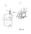
- Fig 1 a schematically shows a level measuring system 1 comprising a tank arrangement 17, and a host system 10 illustrated as a control room.
- the tank arrangement 17 comprises a radar level gauge 2 of GWR (Guided Wave Radar) type and a tank 4 having a tubular mounting structure 13 (often referred to as a "nozzle") extending substantially vertically from the roof of the tank 4.
- GWR Guard Wave Radar
- the radar level gauge 2 is installed to measure the filling level of a product 3 contained in the tank 4.
- the radar level gauge 2 comprises a measuring unit 6 and a propagation device in the form of a single conductor probe 7 extending from the measuring unit 6, through the tubular mounting structure 13, towards and into the product 3.
- the single conductor probe 7 is a wire probe having a first end 18 connected to the measuring unit 6 and a second end 19 connected to a probe aligning member, in the form of a weight 8, to keep the wire straight and vertical.
- the probe aligning member 8 has a conical top portion and a cylindrical bottom portion, where the conical top portion has a length that corresponds to at least one half of the center wavelength of the transmit signal of the guided wave radar level gauge system.
- Various configurations of the probe aligning member 8 will be described further below.
- the measurement unit 6 can determine the distance between a reference position (such as a feed-through between the outside and the inside of the tank) and the surface 11 of the product 3, whereby the filling level L can be deduced. It should be noted that, although a tank 4 containing a single product 3 is discussed herein, the distance to any material interface along the probe can be measured in a similar manner.
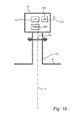
- the measurement unit 6 comprises a transceiver 120, processing circuitry 121, a communication interface 122, and a communication antenna 123 for wireless communication with the control room 10.
- the transceiver is configured to generate, transmit and receive electromagnetic signals
- the processing circuitry is connected to the transceiver and configured to determine the filling level L of the product 3 based on a received electromagnetic reflection signal S R being a reflection of the transmit signal S T at the surface 11 of the product 3, and the communication interface is connected to the processing circuitry and configured to allow communication with the host system 10.
- the communication between the radar level gauge 2 and the host system 10 is indicated as being wireless communication. Alternatively, communication may, for example, take place over an analog and/or digital wire-based communication channel.
- the communication channel may be a two-wire 4-20 mA loop and the filling level may be communicated by providing a certain current corresponding to the filling level on the two-wire 4-20 mA loop.
- Digital data may also be sent across such a 4-20 mA loop, using the HART protocol.
- pure digital communication protocols such as Modbus or Foundation Fieldbus may be used.
- the transmit signal will be reflected at further impedance transitions encountered along the probe 7.
- a portion of the transmit signal S T will be guided through the product 3 and be reflected at one or several impedance discontinuities (impedance steps) below the surface 11 of the product 3.
- a conventional probe aligning member may limit the possibility to measure low filling levels accurately.
- fig 2 showing an example of a conventional probe aligning member
- fig 3 schematically showing a portion of an exemplary echo curve for the configuration in fig 2 .
- Fig 2 schematically shows an example of a conventional bottom weight 21 attached to the second end 19 of the flexible single conductor probe 7.
- the conventional bottom weight 21 has first 22a and second 22b chamfered portions, mainly for cosmetic reasons and for facilitating handling of the bottom weight 21.
- the vertical extension of each of the chamfered portions 22a-b may typically be around one cm.
- the bottom weight 21 is located close to the bottom 24 of the tank 4.
- the surface 11 of the product 3 is indicated as being close to the bottom weight 21.
- a portion of the echo curve is schematically shown in fig 3 .
- the echo curve 26 comprises a first echo signal 27 resulting from reflection of the transmit signal at the surface 11 of the product 4, a second echo signal 28 resulting from reflection of the transmit signal at the impedance discontinuity at the interface between the probe 7 and the bottom weight 21, and a third echo signal 29 resulting from reflection of the transmit signal at the impedance discontinuity at the bottom surface 30 of the bottom weight 21.
- All radar level gauge systems have limited capabilities to separate different echoes which are closer to each other than about 20 cm (a bit depending on radar parameters), so the cluster of echoes in fig 3 indicates decreased accuracy.
- the first echo signal 27 and the second echo signal are comparable in magnitude, and it can easily be understood that it will be difficult, or maybe even impossible, to accurately determine filling levels close to the conventional bottom weight 21.
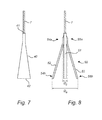
- Fig 4 schematically shows a first configuration of a probe aligning member 31 comprised in a guided wave radar level gauge system according to an embodiment of the present invention
- fig 5 schematically shows a portion of an exemplary echo curve for the configuration in fig 4 .
- the probe aligning member 31 has an upper, substantially conical portion 33, and a lower, substantially cylindrical portion 34.
- the horizontal extension of the probe aligning member 31 increases exponentially with increasing distance from the first end of the probe 7 over a vertical distance d 1 of at least one half of the center wavelength (the wavelength at the center frequency) of the transmit signal S T .
- the vertical distance d 1 should be at least about 30 cm, and for guided wave radar level gauge systems with a pulsed modulated carrier with a bandwidth of about 1-2 GHz or an FMCW-type GWR with the same bandwidth, the vertical distance d 1 should be at least about 10 cm.
- the length d 2 of the cylindrical portion 34 of the probe aligning member 31 in fig 4 is selected to be sufficient to straighten the wire probe 7 and keeping the probe 7 vertically aligned.
- the length of the cylindrical portion 34 of about 0.5 m may give the probe aligning member 31 (made of stainless steel) sufficient mass to straighten and vertically align the wire probe 7.
- the reflection of the transmit signal S T at the interface between probe 7 and probe aligning member 31 can be removed or at least considerably reduced.
- This is schematically illustrated in fig 5 , showing an echo curve 36 comprising a first echo signal 37 resulting from reflection of the transmit signal at the surface 11 of the product 4, and a second echo signal 38 (corresponding to the third echo signal 29 in fig 3 ) resulting from reflection of the transmit signal at the impedance discontinuity at the interface between the probe 7 and the bottom weight 31.
- the probe aligning member 31 in fig 4 allows filling level measurements closer to the bottom 24 of the tank than is possible with the conventional bottom weight 21 in fig 2 .
- a suitable dimensioning of the probe aligning member 31 in fig 4 will depend on various factors, including for example the frequency range of the transmit signal S T , the dimensions of the wire probe 7, and the size of the available opening in the tank roof.
- a frequency range corresponding to the wave number range 2 - 20 m -1 is required.
- the wave number range of about 21 - 42m -1 is required.
- the reflection factor 0.025 (or -36 dB) is marked as a possible maximum level for a custody transfer system.
- the probe aligning member 40 exhibits a gradually increasing horizontal extension all the way from top 41 to bottom 42.
- Fig 8 schematically shows a second alternative configuration, in which the probe aligning member 50 comprises a central bar 51 and first 52 and second 53 flexible bars.
- a first bar end 54a of the first flexible bar 52, and a first bar end 55a of the second flexible bar 53 are attached to the central bar 51.
- the first flexible bar 52 extends from its first bar end 54a to its second bar end 54b in a first direction deviating from the vertical direction
- the second flexible bar 53 extends from its first bar end 55a to its second bar end 55b in a second direction also deviating from the vertical direction.
- the horizontal extension of the probe aligning member 50 increases with increasing vertical distance from the first probe end to an expanded horizontal extension D e .
- the expanded horizontal extension D e provides for efficient impedance matching, but may be too large to allow insertion of the probe aligning member through an opening in the roof of the tank 4.
- the maximum horizontal extension of the probe aligning member 50 in fig 8 can therefore be reduced to a compressed horizontal extension D c by pressing the flexible bars 52, 53 towards the central bar 51.
- the probe aligning member 50 springs back to the expanded state.
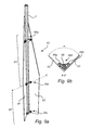
- the probe aligning member 60 comprises a conductive structure with first 61 and second 62 longitudinally extending substantially planar portions forming an angle ⁇ in respect of each other.
- the longitudinal portions are shaped such that the probe aligning member 60 exhibits a top portion 63 with a gradually increasing horizontal extension with increasing distance from the first end of the probe 7, and a bottom portion 64 with a substantially constant horizontal extension.
- the probe aligning member 60 in figs 9a-b further comprises a number of fasteners 66a-c.
- each fastener comprises a plate 68 and two screws 69a-b for pressing the probe 7 between the plate 68 and the inner corner of the angle trim-like conductive structure of the probe aligning member 60 in figs 9a-b .
Abstract
Description
- The present invention relates to a guided wave radar level gauge system comprising a single conductor probe and a probe aligning member for keeping the flexible single conductor probe substantially vertically aligned.
- Radar level gauge (RLG) systems are in wide use for determining the filling level of a product contained in a tank. Radar level gauging is generally performed either by means of non-contact measurement, whereby electromagnetic signals are radiated towards the product contained in the tank, or by means of contact measurement, often referred to as guided wave radar (GWR), whereby electromagnetic signals are guided towards and into the product by a transmission line probe acting as a waveguide. The probe is generally arranged to extend vertically from the top towards the bottom of the tank. In the case of the probe being a flexible single conductor probe, the probe may be kept substantially vertical by means of a weight attached to the bottom end of the flexible single conductor probe.
- An electromagnetic transmit signal is generated by a transceiver and propagated by the probe towards the surface of the product in the tank, and an electromagnetic reflection signal resulting from reflection of the transmit signal at the surface is propagated back towards to the transceiver.
- Based on the transmit signal and the reflection signal, the distance to the surface of the product can be determined.
- Most radar level gauge systems on the market today are either so-called pulsed radar level gauge systems that determine the distance to the surface of the product contained in the tank based on the difference in time between transmission of a pulse and reception of its reflection at the surface of the product, or systems that determine the distance to the surface based on the variation of the phase difference between a transmitted swept (frequency-modulated) signal and its reflection at the surface. The latter type of system is generally referred to as being of the FMCW (Frequency Modulated Continuous Wave) type. The pulsed systems commonly used for GWR use a train of short DC pulses (∼1 ns) processed in a way called TDR (Time Domain Reflectometry).
- In any case, the transmit signal is typically not only reflected at the impedance transition constituted by the interface between the tank atmosphere and the surface of the product, but at several other impedance transitions encountered by the transmit signal. In the case of a GWR-system, one such impedance transition typically occurs at the connection between the transceiver and the probe and another such impedance transition occurs at the bottom end of the probe. The impedance transition at the bottom end of the probe may make it difficult to accurately determine filling levels close to the bottom end of the probe.
- In view of the above, a general object of the present invention is to provide for an improved guided wave radar level gauge system, in particular a guided wave radar level gauge system providing for improved filling level determination close to a bottom end of the probe comprised in the guided wave radar level gauge system.
- According to the present invention, it is therefore provided a guided wave radar level gauge system, for determining a filling level of a product contained in a tank, the guided wave radar level gauge system comprising: a transceiver for generating, transmitting and receiving electromagnetic signals within a predetermined frequency range having a center frequency; a flexible single conductor probe having a first end connected to the transceiver and extending towards and into the product to a second end of the flexible single conductor probe for guiding an electromagnetic transmit signal from the transceiver through a tank atmosphere towards a surface of the product, and for returning an electromagnetic surface reflection signal resulting from reflection of the transmit signal at the surface back towards the transceiver; a probe aligning member attached to the second end of the flexible single conductor probe for keeping the flexible single conductor probe substantially vertically extending from the first end to the second end, the probe aligning member exhibiting a horizontal extension that increases with increasing distance from the first end of the flexible single conductor probe along a vertical distance greater than one half of a wavelength of the transmit signal at the center frequency; and processing circuitry connected to the transceiver for determining the filling level based on the transmit signal and the surface reflection signal.
- The tank may be any container or vessel capable of containing a product.
- The "transceiver" may be one functional unit capable of transmitting and receiving electromagnetic signals, or may be a system comprising separate transmitter and receiver units.
- The flexible single conductor probe may comprise a wire or cable, and may be substantially pliable.
- The present invention is based on the realization that the range of filling levels that can be accurately measured, using a guided wave radar level gauge system with a flexible single conductor probe with a probe aligning member for keeping the flexible single conductor probe substantially straight and vertical, can be increased by shaping the probe aligning member to provide a gradual impedance transition from the impedance of the probe to the impedance of the probe aligning member (below the shaped portion of the probe aligning member, or at the end of the shaped portion).
- Furthermore, the present inventors have realized that this can be achieved by structuring the electrically conductive probe aligning member such that it exhibits a horizontal extension that increases with increasing distance from the first end of the flexible probe along a distance greater than one half of a center wavelength of the transmit signal.
- This will provide for a smooth impedance transition when the probe aligning member is above the surface of the product as well as when the probe aligning member is submerged in a product with a dielectric constant of about 2.25 or less (such as oil). As a consequence, the reflection signal (echo) at the interface between the probe and the probe aligning member will be negligible as compared to currently used probe aligning members (a substantially cylindrical weight), which in turn means that filling levels close to the interface between the probe and the probe alignment member can be measured more accurately.
- It should be noted that the above-mentioned vertical distance is specified to be greater than one half of a wavelength of the transmit signal at the center frequency of the transmit signal. The commonly used TDR systems use the frequency range abound 0.1-1 GHz in the middle of which half a wavelength is 30 cm. A bit higher frequencies may be used in future GWR-systems, decreasing said length (one half of the center wavelength) to 10-15 cm, but with higher frequencies the losses along a GWR-wire will increase too.
- Existing probe aligning members (substantially cylindrical weights), on the other hand, sometimes exhibit an increasing horizontal extension (a frustoconical portion) along a vertical distance of around 1 cm. The purpose of such a chamfer between the vertical envelope surface and the horizontal top surface of an existing substantially cylindrical weight is mainly cosmetic. Such a chamfer has practically no effect on the electrical properties of the probe aligning member for frequency ranges useable for guided wave radar level gauging.
- To the inventors' knowledge, the problem of a relatively strong reflection signal resulting from reflection of the transmit signal at the interface between probe and probe aligning member has not previously been addressed, in particular not by configuring the probe aligning member to have a very long (in relation to existing probe aligning members/weights) portion with increasing horizontal extension.
- It should be noted that the probe aligning member need not necessarily be rotationally symmetrical in respect of the vertical axis (when the probe aligning member is installed in a tank). For instance, a cross-section of the probe aligning member may have a major axis and a minor axis. In embodiments, the probe aligning member may even be substantially planar, for example made of sheet metal. In such embodiments, where the probe aligning member exhibits, for each vertical position, a maximum horizontal extension, it is this maximum horizontal extension that increases with increasing distance from the first end of the flexible single conductor probe.
- To provide for the desired smooth impedance transition, while still allowing easy insertion into most existing suitable openings through the roof of a tank, the horizontal extension of the probe aligning member may increase from a first horizontal extension substantially corresponding to a diameter of the flexible single conductor probe to a second horizontal extension being less than or equal to 5 cm. Even more advantageously, the second horizontal extension may be less than, say, 3 cm.
- According to various embodiments of the guided wave radar level gauge system of the present invention, the probe aligning member may advantageously have a mass being greater than half a total mass of the flexible single conductor probe. Hereby, the flexible single conductor probe can be kept stretched (substantially straight) and substantially vertical. Even more advantageously, from the perspective of stretching and aligning the flexible single conductor probe, the probe aligning member may have a mass being greater than the total mass of the flexible single conductor probe.
- Furthermore, to achieve the desired smooth impedance transition along a relatively short vertical distance, the horizontal extension may advantageously increase exponentially with increasing distance from the first end of the flexible single conductor probe.
- According to various embodiments, the probe aligning member may advantageously comprise a substantially conical portion. For a desired relation between maximum horizontal extension and length (vertical extension) of the probe aligning member, a conical portion will provide the largest mass per unit length. Hence, configurations of the probe aligning member with a substantially conical portion will be able to provide a desired combination of a smooth impedance transition and easy insertion through existing holes (relatively small diameter/maximum horizontal extension) at a shorter total length of the probe aligning member than other configurations of the probe aligning member.
- To further optimize the probe aligning member in the trade off between electrical performance, easy insertion, sufficient mass and total length, the probe aligning member may advantageously comprise a substantially cylindrical portion below the substantially conical portion.
- More generally, the probe aligning member may advantageously comprise: a first portion exhibiting the horizontal extension that increases with increasing distance from the first end of the flexible single conductor probe along a vertical distance greater than one half of a wavelength of the transmit signal at the center frequency; and a second portion, further away from the first end of the flexible single conductor probe than the first portion, exhibiting a substantially constant horizontal extension.
- These embodiments, with a first portion with increasing horizontal extension and a second portion with a substantially constant horizontal extension, are based on the realization that it is relatively easy to get a sufficiently small reflection of the transmit signal at the interface between the first portion and the second portion. These embodiments provide for a favorable trade-off between a considerably reduced reflection at the probe aligning member and length (vertical extension) of the probe aligning member, while at the same time having a sufficient mass to keep the flexible probe straight and vertical and allowing insertion through most existing openings in tank roofs.
- According to various embodiments, the probe aligning member may comprise a vertically extending bore accommodating a portion of the flexible single conductor probe.
- According to other embodiments, the probe aligning member may comprise a conductive structure with first and second longitudinally extending substantially planar portions forming an angle with respect to each other, and at least one fixing structure pressing the flexible single conductor probe against the probe conductive structure inside the angle.
- In these embodiments, the probe aligning member may be substantially shaped as an angle trim with increasing horizontal extension. For instance, the planar portions may be cut to provide the desired increasing horizontal extension. The at least one fixing structure may, for example, comprise a metal plate and at least one screw for pressing the flexible single conductor probe between the metal plate and the inner corner of the angle trim by screwing the at least one screw into a corresponding screw hole formed in the angle trim.
- According to still further embodiments, the probe aligning member may comprise a plurality of flexible bars, each having a first bar end and a second bar end, the first bar end of each of the flexible bars being connected to the flexible single conductor probe, and each of the bars, in an expanded state of the probe aligning member, extending from the first bar end in a direction deviating from the vertical direction to provide a tapered probe aligning member, wherein at least one of the bars may be temporarily deflected to place the probe aligning member in a compressed state in which a maximum horizontal extension of the probe aligning member is reduced compared to the expanded state.
- In summary, the present invention thus relates to a guided wave radar level gauge system comprising a transceiver for generating an electromagnetic transmit signal within a predetermined frequency range having a center frequency, a flexible single conductor probe having a first end connected to the transceiver and extending towards and into the product to a second end of the flexible single conductor probe; and a probe aligning member attached to the second end of the flexible single conductor probe for keeping the flexible single conductor probe substantially vertically extending from the first end to the second end. The probe aligning member exhibits a horizontal extension that increases with increasing distance from the first end of the flexible single conductor probe along a vertical distance greater than one half of a wavelength of the transmit signal at the center frequency. Hereby, determination of filling levels close to the bottom of the tank is improved.
- These and other aspects of the present invention will now be described in more detail, with reference to the appended drawings showing an example embodiment of the invention, wherein:
-
Fig 1 a schematically illustrates an exemplary tank arrangement comprising a radar level gauge system according to an embodiment of the present invention; -
Fig 1b is a schematic illustration of the measurement electronics unit comprised in the radar level gauge system infig 1 a; -
Fig 2 schematically illustrates a probe aligning member according to the prior art; -
Fig 3 is schematically illustrates an exemplary echo profile obtained using the radar level gauge system infig 1 a with the probe aligning member infig 2 ; -
Fig 4 schematically illustrates a probe aligning member comprised in a guided wave radar level gauge system according to a first embodiment of the present invention; -
Fig 5 is schematically illustrates an exemplary echo profile obtained using the radar level gauge system infig 1 a with the probe aligning member infig 4 ; -
Fig 6 illustrates the reflection from the interface between probe and probe aligning member as a function of wave number for some different probe aligning member configurations; -
Fig 7 schematically shows a first alternative configuration of the probe aligning member; -
Fig 8 schematically shows a second alternative configuration of the probe aligning member; and -
Figs 9a-b schematically show a third alternative configuration of the probe aligning member. -
Fig 1 a schematically shows a level measuring system 1 comprising atank arrangement 17, and ahost system 10 illustrated as a control room. - The
tank arrangement 17 comprises aradar level gauge 2 of GWR (Guided Wave Radar) type and atank 4 having a tubular mounting structure 13 (often referred to as a "nozzle") extending substantially vertically from the roof of thetank 4. - The
radar level gauge 2 is installed to measure the filling level of aproduct 3 contained in the tank 4.Theradar level gauge 2 comprises a measuringunit 6 and a propagation device in the form of asingle conductor probe 7 extending from the measuringunit 6, through thetubular mounting structure 13, towards and into theproduct 3. In the example embodiment infig 1a , thesingle conductor probe 7 is a wire probe having a first end 18 connected to the measuringunit 6 and asecond end 19 connected to a probe aligning member, in the form of aweight 8, to keep the wire straight and vertical. Theprobe aligning member 8 has a conical top portion and a cylindrical bottom portion, where the conical top portion has a length that corresponds to at least one half of the center wavelength of the transmit signal of the guided wave radar level gauge system. Various configurations of theprobe aligning member 8 will be described further below. - By analyzing transmitted signals ST being guided by the
probe 7 towards thesurface 11 of theproduct 3, and reflected signals SR traveling back from thesurface 11, themeasurement unit 6 can determine the distance between a reference position (such as a feed-through between the outside and the inside of the tank) and thesurface 11 of theproduct 3, whereby the filling level L can be deduced. It should be noted that, although atank 4 containing asingle product 3 is discussed herein, the distance to any material interface along the probe can be measured in a similar manner. - As is schematically illustrated in
fig 1b , themeasurement unit 6 comprises atransceiver 120,processing circuitry 121, acommunication interface 122, and acommunication antenna 123 for wireless communication with thecontrol room 10. - The transceiver is configured to generate, transmit and receive electromagnetic signals, the processing circuitry is connected to the transceiver and configured to determine the filling level L of the
product 3 based on a received electromagnetic reflection signal SR being a reflection of the transmit signal ST at thesurface 11 of theproduct 3, and the communication interface is connected to the processing circuitry and configured to allow communication with thehost system 10. In the example embodiment offig 1a , the communication between theradar level gauge 2 and thehost system 10 is indicated as being wireless communication. Alternatively, communication may, for example, take place over an analog and/or digital wire-based communication channel. For instance, the communication channel may be a two-wire 4-20 mA loop and the filling level may be communicated by providing a certain current corresponding to the filling level on the two-wire 4-20 mA loop. Digital data may also be sent across such a 4-20 mA loop, using the HART protocol. Furthermore, pure digital communication protocols such as Modbus or Foundation Fieldbus may be used. - In addition to above-mentioned surface reflection signal resulting from reflection of the transmit signal at the
surface 11 of theproduct 3 in thetank 4, the transmit signal will be reflected at further impedance transitions encountered along theprobe 7. For products that are at least partly transparent to the microwaves, such as oil, a portion of the transmit signal ST will be guided through theproduct 3 and be reflected at one or several impedance discontinuities (impedance steps) below thesurface 11 of theproduct 3. - For filling levels high up in the tank, echo signals from impedance discontinuities far down in the tank can generally be ignored, but for filling levels close to the bottom of the tank, the filling level measurement may be disturbed by such impedance discontinuities.
- For example, the present inventors have noticed that a conventional probe aligning member (bottom weight) may limit the possibility to measure low filling levels accurately. This will now be described with reference to
fig 2 showing an example of a conventional probe aligning member andfig 3 schematically showing a portion of an exemplary echo curve for the configuration infig 2 . -
Fig 2 schematically shows an example of a conventionalbottom weight 21 attached to thesecond end 19 of the flexiblesingle conductor probe 7. As is schematically indicated infig 2 , the conventionalbottom weight 21 has first 22a and second 22b chamfered portions, mainly for cosmetic reasons and for facilitating handling of thebottom weight 21. The vertical extension of each of the chamferedportions 22a-b may typically be around one cm. Thebottom weight 21 is located close to the bottom 24 of thetank 4. - In
fig 2 , thesurface 11 of theproduct 3 is indicated as being close to thebottom weight 21. For a product (such as oil) that is rather transparent to microwaves, a portion of the echo curve is schematically shown infig 3 . Referring tofig 3 , theecho curve 26 comprises afirst echo signal 27 resulting from reflection of the transmit signal at thesurface 11 of theproduct 4, asecond echo signal 28 resulting from reflection of the transmit signal at the impedance discontinuity at the interface between theprobe 7 and thebottom weight 21, and athird echo signal 29 resulting from reflection of the transmit signal at the impedance discontinuity at thebottom surface 30 of thebottom weight 21. - All radar level gauge systems have limited capabilities to separate different echoes which are closer to each other than about 20 cm (a bit depending on radar parameters), so the cluster of echoes in
fig 3 indicates decreased accuracy. - As is clear from the
echo curve 26 infig 3 , thefirst echo signal 27 and the second echo signal are comparable in magnitude, and it can easily be understood that it will be difficult, or maybe even impossible, to accurately determine filling levels close to the conventionalbottom weight 21. -
Fig 4 schematically shows a first configuration of aprobe aligning member 31 comprised in a guided wave radar level gauge system according to an embodiment of the present invention, andfig 5 schematically shows a portion of an exemplary echo curve for the configuration infig 4 . - Referring to
fig 4 , theprobe aligning member 31 has an upper, substantiallyconical portion 33, and a lower, substantiallycylindrical portion 34. In theupper portion 33, the horizontal extension of theprobe aligning member 31 increases exponentially with increasing distance from the first end of theprobe 7 over a vertical distance d1 of at least one half of the center wavelength (the wavelength at the center frequency) of the transmit signal ST. For a conventional TDR (time domain reflectometry) radar level gauge systems, the vertical distance d1 should be at least about 30 cm, and for guided wave radar level gauge systems with a pulsed modulated carrier with a bandwidth of about 1-2 GHz or an FMCW-type GWR with the same bandwidth, the vertical distance d1 should be at least about 10 cm. - The length d2 of the
cylindrical portion 34 of theprobe aligning member 31 infig 4 is selected to be sufficient to straighten thewire probe 7 and keeping theprobe 7 vertically aligned. For an exemplary case with a 6 mmdiameter wire probe 7 that is about 10 m long, and anupper portion 33 of theprobe aligning member 31 that is about 0.6 m long, the length of thecylindrical portion 34 of about 0.5 m may give the probe aligning member 31 (made of stainless steel) sufficient mass to straighten and vertically align thewire probe 7. - With a sufficiently
long portion 33 of theprobe aligning member 31 having a gradually increasing horizontal extension, the reflection of the transmit signal ST at the interface betweenprobe 7 and probe aligningmember 31 can be removed or at least considerably reduced. This is schematically illustrated infig 5 , showing anecho curve 36 comprising afirst echo signal 37 resulting from reflection of the transmit signal at thesurface 11 of theproduct 4, and a second echo signal 38 (corresponding to thethird echo signal 29 infig 3 ) resulting from reflection of the transmit signal at the impedance discontinuity at the interface between theprobe 7 and thebottom weight 31. Compared to theecho curve 26 infig 3 , it is clear that theprobe aligning member 31 infig 4 allows filling level measurements closer to the bottom 24 of the tank than is possible with the conventionalbottom weight 21 infig 2 . - A suitable dimensioning of the
probe aligning member 31 infig 4 will depend on various factors, including for example the frequency range of the transmit signal ST, the dimensions of thewire probe 7, and the size of the available opening in the tank roof. -
Fig 6 schematically shows simulation results in the form of the reflection factor for the top of theprobe aligning member 31 as a function of wave number (=2π/λ which is 21 m-1 at 1 GHz) for two different lengths d1 of the substantiallyconical portion 33 and two different values of the maximum horizontal extension D of the probe aligning member 31 (in this case the diameter of the cylindrical portion 34). - For a typical conventional TDR-system, a frequency range corresponding to the wave number range 2 - 20 m-1 is required. For an FMCW-type GWR system using a frequency range of about 1 - 2 GHz, the wave number range of about 21 - 42m-1 is required. The reflection factor 0.025 (or -36 dB) is marked as a possible maximum level for a custody transfer system. However, this reflection limit is only provided as an example. It should also be noted that other applications than custody transfer systems may have considerably less severe requirements on the maximum reflection factor at the interface between
probe 7 and probe aligningmember 31. For a 1-2 GHz system the length d1 = 0.3 m may be sufficient to fulfil the severe requirements of a custody transfer system. - For a conventional TDR-system (with an approximate frequency range of 0.1-1 GHz), reflection will grow for low frequencies, but it is expected that a tapering
portion 33 that is at least 0.6 m long should give acceptable performance. - It should be noted that several alternative configurations of the probe aligning member are feasible. Three such alternative configurations are schematically shown in
fig 7, fig 8 , andfigs 9a-b , respectively. - Referring first to
fig 7 , in a first alternative configuration, theprobe aligning member 40 exhibits a gradually increasing horizontal extension all the way from top 41 tobottom 42. -
Fig 8 schematically shows a second alternative configuration, in which theprobe aligning member 50 comprises acentral bar 51 and first 52 and second 53 flexible bars. Afirst bar end 54a of the firstflexible bar 52, and afirst bar end 55a of the secondflexible bar 53 are attached to thecentral bar 51. In the expanded state, shown using solid lines infig 8 , the firstflexible bar 52 extends from itsfirst bar end 54a to itssecond bar end 54b in a first direction deviating from the vertical direction, and the secondflexible bar 53 extends from itsfirst bar end 55a to itssecond bar end 55b in a second direction also deviating from the vertical direction. In the expanded state, the horizontal extension of theprobe aligning member 50 increases with increasing vertical distance from the first probe end to an expanded horizontal extension De . - The expanded horizontal extension De provides for efficient impedance matching, but may be too large to allow insertion of the probe aligning member through an opening in the roof of the
tank 4. Upon installation, the maximum horizontal extension of theprobe aligning member 50 infig 8 can therefore be reduced to a compressed horizontal extension Dc by pressing theflexible bars central bar 51. When pressure is released, theprobe aligning member 50 springs back to the expanded state. - Finally, a third configuration of the probe aligning member will now be described with reference to
figs 9a-b . - Referring first to
fig 9a , theprobe aligning member 60 comprises a conductive structure with first 61 and second 62 longitudinally extending substantially planar portions forming an angle α in respect of each other. The longitudinal portions are shaped such that theprobe aligning member 60 exhibits atop portion 63 with a gradually increasing horizontal extension with increasing distance from the first end of theprobe 7, and abottom portion 64 with a substantially constant horizontal extension. - The
probe aligning member 60 infigs 9a-b further comprises a number offasteners 66a-c. As is best shown infig 9b , which is a cross-section view of the horizontal plane including the line A-A', each fastener comprises aplate 68 and twoscrews 69a-b for pressing theprobe 7 between theplate 68 and the inner corner of the angle trim-like conductive structure of theprobe aligning member 60 infigs 9a-b . - The person skilled in the art realizes that the present invention by no means is limited to the preferred embodiments described above. On the contrary, many modifications and variations are possible within the scope of the appended claims.
Claims (11)
- A guided wave radar level gauge system, for determining a filling level of a product contained in a tank, said guided wave radar level gauge system comprising:a transceiver for generating, transmitting and receiving electromagnetic signals within a predetermined frequency range having a center frequency;a flexible single conductor probe having a first end connected to said transceiver and extending towards and into said product to a second end of the flexible single conductor probe for guiding an electromagnetic transmit signal from said transceiver through a tank atmosphere towards a surface of the product, and for returning an electromagnetic surface reflection signal resulting from reflection of said transmit signal at said surface back towards said transceiver;a probe aligning member attached to said second end of the flexible single conductor probe for keeping the flexible single conductor probe substantially vertically extending from the first end to the second end,said probe aligning member exhibiting a horizontal extension that increases with increasing distance from said first end of the flexible single conductor probe along a vertical distance greater than one half of a wavelength of said transmit signal at said center frequency; andprocessing circuitry connected to said transceiver for determining said filling level based on said transmit signal and said surface reflection signal.
- The guided wave radar level gauge system according to claim 1, wherein said probe aligning member exhibits a horizontal extension that increases with increasing distance from said first end of the flexible single conductor probe along a vertical distance greater than 10 cm.
- The guided wave radar level gauge system according to claim 1 or 2, wherein said horizontal extension of the probe aligning member increases from a first horizontal extension substantially corresponding to a diameter of said flexible single conductor probe to a second horizontal extension being less than or equal to 5 cm to allow insertion of said probe aligning member through an opening at a top of the tank.
- The guided wave radar level gauge system according to any one of claims 1 to 3, wherein said probe aligning member has a mass being greater than half a total mass of said flexible single conductor probe.
- The guided wave radar level gauge system according to any one of claims 1 to 4, wherein said horizontal extension increases exponentially with increasing distance from said first end of the flexible single conductor probe.
- The guided wave radar level gauge system according to any one of claims 1 to 5, wherein said probe aligning member comprises a substantially conical portion.
- The guided wave radar level gauge system according to claim 6, wherein said probe aligning member comprises a substantially cylindrical portion below said substantially conical portion.
- The guided wave radar level gauge system according to any one of claims 1 to 7, wherein said probe aligning member comprises:a first portion exhibiting said horizontal extension that increases with increasing distance from said first end of the flexible single conductor probe along a vertical distance greater than one half of a wavelength of said transmit signal at said center frequency; anda second portion, further away from said first end of the flexible single conductor probe than said first portion, exhibiting a substantially constant horizontal extension.
- The guided wave radar level gauge system according to any one of claims 1 to 8, wherein said probe aligning member comprises a vertically extending bore accommodating a portion of said flexible single conductor probe.
- The guided wave radar level gauge system according to any one of claims 1 to 5, wherein said probe aligning member comprises a conductive structure with first and second longitudinally extending substantially planar portions forming an angle with respect to each other, and at least one fixing structure pressing said flexible single conductor probe against the probe conductive structure inside the angle.
- The guided wave radar level gauge system according to any one of claims 1 to 5, wherein said probe aligning member comprises a plurality of flexible bars, each having a first bar end and a second bar end,
the first bar end of each of said flexible bars being connected to said flexible single conductor probe, and each of said bars, in an expanded state of said probe aligning member, extending from said first bar end in a direction deviating from the vertical direction to provide a tapered probe aligning member,
wherein at least one of said bars may be temporarily deflected to place said probe aligning member in a compressed state in which a maximum horizontal extension of said probe aligning member is reduced compared to said expanded state.
Applications Claiming Priority (1)
| Application Number | Priority Date | Filing Date | Title |
|---|---|---|---|
| US14/513,538 US9518858B2 (en) | 2014-10-14 | 2014-10-14 | Guided wave radar level gauge system with reduced end of probe reflection |
Publications (2)
| Publication Number | Publication Date |
|---|---|
| EP3021092A1 true EP3021092A1 (en) | 2016-05-18 |
| EP3021092B1 EP3021092B1 (en) | 2017-11-08 |
Family
ID=53329951
Family Applications (1)
| Application Number | Title | Priority Date | Filing Date |
|---|---|---|---|
| EP15186082.2A Active EP3021092B1 (en) | 2014-10-14 | 2015-09-21 | Guided wave radar level gauge system with reduced end of probe reflection |
Country Status (3)
| Country | Link |
|---|---|
| US (1) | US9518858B2 (en) |
| EP (1) | EP3021092B1 (en) |
| CN (2) | CN105737943B (en) |
Families Citing this family (9)
| Publication number | Priority date | Publication date | Assignee | Title |
|---|---|---|---|---|
| GB2514493B (en) | 2013-06-14 | 2015-09-23 | Welldata Subsurface Surveillance Systems Ltd | Downhole detection |
| US9518858B2 (en) * | 2014-10-14 | 2016-12-13 | Rosemount Tank Radar Ab | Guided wave radar level gauge system with reduced end of probe reflection |
| US10055519B2 (en) * | 2014-10-23 | 2018-08-21 | Honeywell International Inc. | Pulse shape change for interface determination |
| GB201420938D0 (en) * | 2014-11-25 | 2015-01-07 | Welldata Subsurface Surveillance Systems Ltd | Monitoring structures |
| US10444055B2 (en) * | 2015-09-11 | 2019-10-15 | Honeywell International Inc. | Apparatus and method to detect liquid material at the end of the waveguide in a guided wave radar system |
| US10145939B2 (en) * | 2016-02-25 | 2018-12-04 | Honeywell International Inc. | Recursive multi-model echo curve simulation |
| CN106197616B (en) * | 2016-07-04 | 2019-02-15 | 中国石油集团渤海钻探工程有限公司 | Mud jar liquid surface steady state measurement device |
| US20180328771A1 (en) * | 2017-05-10 | 2018-11-15 | Rosemount Tank Radar Ab | Pulsed radar level gauge system and method for reduced relative bandwidth |
| DE102020132964A1 (en) * | 2020-12-10 | 2022-06-15 | Endress+Hauser SE+Co. KG | Filling level measuring device and method for in-line calibration and/or verification of a filling level measuring device |
Citations (4)
| Publication number | Priority date | Publication date | Assignee | Title |
|---|---|---|---|---|
| US7525476B1 (en) * | 2007-11-13 | 2009-04-28 | Rosemount Tank Radar Ab | System and method for filling level determination |
| EP2490040A1 (en) * | 2011-02-17 | 2012-08-22 | Rosemount Tank Radar AB | Single conductor probe gwr system with reduced end of nozzle reflection |
| WO2014052577A1 (en) * | 2012-09-27 | 2014-04-03 | Magnetrol International, Incorporated | Emulsion measurement and profiling system and method |
| EP2884245A1 (en) * | 2013-12-16 | 2015-06-17 | VEGA Grieshaber KG | Weight apparatus for a waveguide, probe and method for producing a weight apparatus |
Family Cites Families (17)
| Publication number | Priority date | Publication date | Assignee | Title |
|---|---|---|---|---|
| US7334451B1 (en) * | 2005-05-20 | 2008-02-26 | K-Tek Corporation | Level meter threshold detection system |
| US7450055B2 (en) * | 2006-02-22 | 2008-11-11 | Rosemount Tank Radar Ab | Coaxial connector in radar level gauge |
| US7586435B1 (en) * | 2008-05-16 | 2009-09-08 | Rosemount Tank Radar Ab | Radar level gauge system using a waveguiding structure with periodically arranged reference impedance transitions |
| US7741993B1 (en) * | 2009-07-28 | 2010-06-22 | Equistar Chemicals, Lp | Method for locating the surface of a polymer particle bed |
| MX2012006794A (en) * | 2009-12-18 | 2012-10-05 | Total Petrochemicals Res Feluy | Method for monitoring the level of an ethylene polymerization catalyst slurry. |
| CN202195856U (en) * | 2011-07-14 | 2012-04-18 | 南京乌江化工有限公司 | Anti-interference device applied to radar liquid level meter |
| US8963769B2 (en) * | 2012-10-16 | 2015-02-24 | Magnetrol International, Incorporated | Guided wave radar interface measurement medium identification |
| US9151838B2 (en) * | 2012-11-02 | 2015-10-06 | Magnetrol International, Inc. | Ceramic probe rod support assembly |
| US8941532B2 (en) * | 2012-12-06 | 2015-01-27 | Rosemount Tank Radar Ab | Probe spacing element |
| US9291492B2 (en) * | 2013-03-12 | 2016-03-22 | Rosemount Tank Radar Ab | Tank feed through structure for a radar level gauge |
| US20140326038A1 (en) * | 2013-05-01 | 2014-11-06 | Eric Fauveau | In Situ Calibration of a Level Measuring Device |
| US9541443B2 (en) * | 2013-12-23 | 2017-01-10 | Rosemount Tank Radar Ab | Guided wave radar level gauging with probe retaining element |
| US9518856B2 (en) * | 2014-03-28 | 2016-12-13 | Honeywell International Inc. | Threaded coupling device with nozzle for GWR measurements in non-metallic tanks |
| US9841307B2 (en) * | 2014-09-30 | 2017-12-12 | Rosemount Inc. | Multivariable guided wave radar probe |
| US9810568B2 (en) * | 2014-10-13 | 2017-11-07 | Honeywell International Inc. | Use of resilient seals for high temperature and/or high pressure sealing in a guided wave radar level measurement device |
| US9518858B2 (en) * | 2014-10-14 | 2016-12-13 | Rosemount Tank Radar Ab | Guided wave radar level gauge system with reduced end of probe reflection |
| US9638567B2 (en) * | 2014-10-14 | 2017-05-02 | Rosemount Tank Radar Ab | Radar level gauge with foldable probe |
-
2014
- 2014-10-14 US US14/513,538 patent/US9518858B2/en active Active
- 2014-12-12 CN CN201410771181.8A patent/CN105737943B/en not_active Expired - Fee Related
- 2014-12-12 CN CN201420787892.XU patent/CN204373739U/en not_active Withdrawn - After Issue
-
2015
- 2015-09-21 EP EP15186082.2A patent/EP3021092B1/en active Active
Patent Citations (4)
| Publication number | Priority date | Publication date | Assignee | Title |
|---|---|---|---|---|
| US7525476B1 (en) * | 2007-11-13 | 2009-04-28 | Rosemount Tank Radar Ab | System and method for filling level determination |
| EP2490040A1 (en) * | 2011-02-17 | 2012-08-22 | Rosemount Tank Radar AB | Single conductor probe gwr system with reduced end of nozzle reflection |
| WO2014052577A1 (en) * | 2012-09-27 | 2014-04-03 | Magnetrol International, Incorporated | Emulsion measurement and profiling system and method |
| EP2884245A1 (en) * | 2013-12-16 | 2015-06-17 | VEGA Grieshaber KG | Weight apparatus for a waveguide, probe and method for producing a weight apparatus |
Also Published As
| Publication number | Publication date |
|---|---|
| CN204373739U (en) | 2015-06-03 |
| US20160103008A1 (en) | 2016-04-14 |
| CN105737943A (en) | 2016-07-06 |
| CN105737943B (en) | 2019-07-09 |
| EP3021092B1 (en) | 2017-11-08 |
| US9518858B2 (en) | 2016-12-13 |
Similar Documents
| Publication | Publication Date | Title |
|---|---|---|
| EP3021092B1 (en) | Guided wave radar level gauge system with reduced end of probe reflection | |
| US7636059B1 (en) | Impedance matched guided wave radar level gauge system | |
| EP2490040B1 (en) | Single conductor probe gwr system with reduced end of nozzle reflection | |
| KR101680162B1 (en) | System and Method for Filling Level Determination | |
| EP3161427B1 (en) | Single conductor probe radar level gauge system | |
| KR101680161B1 (en) | Radar Level Gauge System Using a Waveguiding Structure with Periodically Arranged Reference Impedance Transitions | |
| CN105737942B (en) | Guided wave radar level meter based on frequency modulation continuous wave | |
| US9671488B2 (en) | Radar level gauge with signal division | |
| EP3301412A1 (en) | Guided wave radar level gauge system with dual transmission line probes for dielectric constant compensation | |
| CN108225483B (en) | Tank arrangement | |
| EP3425351B1 (en) | Radar level gauge system having longitudinally open two-conductor probe, and method of assembly of the level gauge system | |
| EP3857183B1 (en) | System and method for determining level and density distribution | |
| EP3688421B1 (en) | Radar level gauging with wait state | |
| EP3405757B1 (en) | Radar level gauge system and method with signal propagation path modeling | |
| EP3959490B1 (en) | Pulsed rlg with improved resistance to signal disturbance |
Legal Events
| Date | Code | Title | Description |
|---|---|---|---|
| PUAI | Public reference made under article 153(3) epc to a published international application that has entered the european phase |
Free format text: ORIGINAL CODE: 0009012 |
|
| AK | Designated contracting states |
Kind code of ref document: A1 Designated state(s): AL AT BE BG CH CY CZ DE DK EE ES FI FR GB GR HR HU IE IS IT LI LT LU LV MC MK MT NL NO PL PT RO RS SE SI SK SM TR |
|
| AX | Request for extension of the european patent |
Extension state: BA ME |
|
| 17P | Request for examination filed |
Effective date: 20161115 |
|
| RBV | Designated contracting states (corrected) |
Designated state(s): AL AT BE BG CH CY CZ DE DK EE ES FI FR GB GR HR HU IE IS IT LI LT LU LV MC MK MT NL NO PL PT RO RS SE SI SK SM TR |
|
| REG | Reference to a national code |
Ref country code: DE Ref legal event code: R079 Ref document number: 602015005844 Country of ref document: DE Free format text: PREVIOUS MAIN CLASS: G01F0023284000 Ipc: G01F0001690000 |
|
| GRAP | Despatch of communication of intention to grant a patent |
Free format text: ORIGINAL CODE: EPIDOSNIGR1 |
|
| INTG | Intention to grant announced |
Effective date: 20170508 |
|
| RIC1 | Information provided on ipc code assigned before grant |
Ipc: G01F 1/64 20060101ALI20170421BHEP Ipc: G01F 1/69 20060101AFI20170421BHEP |
|
| RAP1 | Party data changed (applicant data changed or rights of an application transferred) |
Owner name: ROSEMOUNT TANK RADAR AB |
|
| GRAS | Grant fee paid |
Free format text: ORIGINAL CODE: EPIDOSNIGR3 |
|
| GRAA | (expected) grant |
Free format text: ORIGINAL CODE: 0009210 |
|
| AK | Designated contracting states |
Kind code of ref document: B1 Designated state(s): AL AT BE BG CH CY CZ DE DK EE ES FI FR GB GR HR HU IE IS IT LI LT LU LV MC MK MT NL NO PL PT RO RS SE SI SK SM TR |
|
| REG | Reference to a national code |
Ref country code: GB Ref legal event code: FG4D |
|
| REG | Reference to a national code |
Ref country code: CH Ref legal event code: EP Ref country code: AT Ref legal event code: REF Ref document number: 944575 Country of ref document: AT Kind code of ref document: T Effective date: 20171115 |
|
| REG | Reference to a national code |
Ref country code: IE Ref legal event code: FG4D |
|
| REG | Reference to a national code |
Ref country code: DE Ref legal event code: R096 Ref document number: 602015005844 Country of ref document: DE |
|
| REG | Reference to a national code |
Ref country code: CH Ref legal event code: NV Representative=s name: OFFICE ERNEST T. FREYLINGER S.A., CH |
|
| REG | Reference to a national code |
Ref country code: NL Ref legal event code: MP Effective date: 20171108 |
|
| REG | Reference to a national code |
Ref country code: LT Ref legal event code: MG4D |
|
| REG | Reference to a national code |
Ref country code: AT Ref legal event code: MK05 Ref document number: 944575 Country of ref document: AT Kind code of ref document: T Effective date: 20171108 |
|
| PG25 | Lapsed in a contracting state [announced via postgrant information from national office to epo] |
Ref country code: NL Free format text: LAPSE BECAUSE OF FAILURE TO SUBMIT A TRANSLATION OF THE DESCRIPTION OR TO PAY THE FEE WITHIN THE PRESCRIBED TIME-LIMIT Effective date: 20171108 Ref country code: ES Free format text: LAPSE BECAUSE OF FAILURE TO SUBMIT A TRANSLATION OF THE DESCRIPTION OR TO PAY THE FEE WITHIN THE PRESCRIBED TIME-LIMIT Effective date: 20171108 Ref country code: LT Free format text: LAPSE BECAUSE OF FAILURE TO SUBMIT A TRANSLATION OF THE DESCRIPTION OR TO PAY THE FEE WITHIN THE PRESCRIBED TIME-LIMIT Effective date: 20171108 Ref country code: FI Free format text: LAPSE BECAUSE OF FAILURE TO SUBMIT A TRANSLATION OF THE DESCRIPTION OR TO PAY THE FEE WITHIN THE PRESCRIBED TIME-LIMIT Effective date: 20171108 Ref country code: SE Free format text: LAPSE BECAUSE OF FAILURE TO SUBMIT A TRANSLATION OF THE DESCRIPTION OR TO PAY THE FEE WITHIN THE PRESCRIBED TIME-LIMIT Effective date: 20171108 Ref country code: NO Free format text: LAPSE BECAUSE OF FAILURE TO SUBMIT A TRANSLATION OF THE DESCRIPTION OR TO PAY THE FEE WITHIN THE PRESCRIBED TIME-LIMIT Effective date: 20180208 |
|
| PG25 | Lapsed in a contracting state [announced via postgrant information from national office to epo] |
Ref country code: GR Free format text: LAPSE BECAUSE OF FAILURE TO SUBMIT A TRANSLATION OF THE DESCRIPTION OR TO PAY THE FEE WITHIN THE PRESCRIBED TIME-LIMIT Effective date: 20180209 Ref country code: RS Free format text: LAPSE BECAUSE OF FAILURE TO SUBMIT A TRANSLATION OF THE DESCRIPTION OR TO PAY THE FEE WITHIN THE PRESCRIBED TIME-LIMIT Effective date: 20171108 Ref country code: IS Free format text: LAPSE BECAUSE OF FAILURE TO SUBMIT A TRANSLATION OF THE DESCRIPTION OR TO PAY THE FEE WITHIN THE PRESCRIBED TIME-LIMIT Effective date: 20180308 Ref country code: LV Free format text: LAPSE BECAUSE OF FAILURE TO SUBMIT A TRANSLATION OF THE DESCRIPTION OR TO PAY THE FEE WITHIN THE PRESCRIBED TIME-LIMIT Effective date: 20171108 Ref country code: BG Free format text: LAPSE BECAUSE OF FAILURE TO SUBMIT A TRANSLATION OF THE DESCRIPTION OR TO PAY THE FEE WITHIN THE PRESCRIBED TIME-LIMIT Effective date: 20180208 Ref country code: HR Free format text: LAPSE BECAUSE OF FAILURE TO SUBMIT A TRANSLATION OF THE DESCRIPTION OR TO PAY THE FEE WITHIN THE PRESCRIBED TIME-LIMIT Effective date: 20171108 Ref country code: AT Free format text: LAPSE BECAUSE OF FAILURE TO SUBMIT A TRANSLATION OF THE DESCRIPTION OR TO PAY THE FEE WITHIN THE PRESCRIBED TIME-LIMIT Effective date: 20171108 |
|
| PG25 | Lapsed in a contracting state [announced via postgrant information from national office to epo] |
Ref country code: SK Free format text: LAPSE BECAUSE OF FAILURE TO SUBMIT A TRANSLATION OF THE DESCRIPTION OR TO PAY THE FEE WITHIN THE PRESCRIBED TIME-LIMIT Effective date: 20171108 Ref country code: CY Free format text: LAPSE BECAUSE OF FAILURE TO SUBMIT A TRANSLATION OF THE DESCRIPTION OR TO PAY THE FEE WITHIN THE PRESCRIBED TIME-LIMIT Effective date: 20171108 Ref country code: EE Free format text: LAPSE BECAUSE OF FAILURE TO SUBMIT A TRANSLATION OF THE DESCRIPTION OR TO PAY THE FEE WITHIN THE PRESCRIBED TIME-LIMIT Effective date: 20171108 Ref country code: DK Free format text: LAPSE BECAUSE OF FAILURE TO SUBMIT A TRANSLATION OF THE DESCRIPTION OR TO PAY THE FEE WITHIN THE PRESCRIBED TIME-LIMIT Effective date: 20171108 Ref country code: CZ Free format text: LAPSE BECAUSE OF FAILURE TO SUBMIT A TRANSLATION OF THE DESCRIPTION OR TO PAY THE FEE WITHIN THE PRESCRIBED TIME-LIMIT Effective date: 20171108 |
|
| REG | Reference to a national code |
Ref country code: DE Ref legal event code: R097 Ref document number: 602015005844 Country of ref document: DE |
|
| PG25 | Lapsed in a contracting state [announced via postgrant information from national office to epo] |
Ref country code: IT Free format text: LAPSE BECAUSE OF FAILURE TO SUBMIT A TRANSLATION OF THE DESCRIPTION OR TO PAY THE FEE WITHIN THE PRESCRIBED TIME-LIMIT Effective date: 20171108 Ref country code: PL Free format text: LAPSE BECAUSE OF FAILURE TO SUBMIT A TRANSLATION OF THE DESCRIPTION OR TO PAY THE FEE WITHIN THE PRESCRIBED TIME-LIMIT Effective date: 20171108 Ref country code: SM Free format text: LAPSE BECAUSE OF FAILURE TO SUBMIT A TRANSLATION OF THE DESCRIPTION OR TO PAY THE FEE WITHIN THE PRESCRIBED TIME-LIMIT Effective date: 20171108 Ref country code: RO Free format text: LAPSE BECAUSE OF FAILURE TO SUBMIT A TRANSLATION OF THE DESCRIPTION OR TO PAY THE FEE WITHIN THE PRESCRIBED TIME-LIMIT Effective date: 20171108 |
|
| PLBE | No opposition filed within time limit |
Free format text: ORIGINAL CODE: 0009261 |
|
| STAA | Information on the status of an ep patent application or granted ep patent |
Free format text: STATUS: NO OPPOSITION FILED WITHIN TIME LIMIT |
|
| 26N | No opposition filed |
Effective date: 20180809 |
|
| PG25 | Lapsed in a contracting state [announced via postgrant information from national office to epo] |
Ref country code: SI Free format text: LAPSE BECAUSE OF FAILURE TO SUBMIT A TRANSLATION OF THE DESCRIPTION OR TO PAY THE FEE WITHIN THE PRESCRIBED TIME-LIMIT Effective date: 20171108 |
|
| PG25 | Lapsed in a contracting state [announced via postgrant information from national office to epo] |
Ref country code: MC Free format text: LAPSE BECAUSE OF FAILURE TO SUBMIT A TRANSLATION OF THE DESCRIPTION OR TO PAY THE FEE WITHIN THE PRESCRIBED TIME-LIMIT Effective date: 20171108 |
|
| REG | Reference to a national code |
Ref country code: BE Ref legal event code: MM Effective date: 20180930 |
|
| REG | Reference to a national code |
Ref country code: IE Ref legal event code: MM4A |
|
| PG25 | Lapsed in a contracting state [announced via postgrant information from national office to epo] |
Ref country code: LU Free format text: LAPSE BECAUSE OF NON-PAYMENT OF DUE FEES Effective date: 20180921 |
|
| PG25 | Lapsed in a contracting state [announced via postgrant information from national office to epo] |
Ref country code: IE Free format text: LAPSE BECAUSE OF NON-PAYMENT OF DUE FEES Effective date: 20180921 |
|
| PG25 | Lapsed in a contracting state [announced via postgrant information from national office to epo] |
Ref country code: FR Free format text: LAPSE BECAUSE OF NON-PAYMENT OF DUE FEES Effective date: 20180930 Ref country code: BE Free format text: LAPSE BECAUSE OF NON-PAYMENT OF DUE FEES Effective date: 20180930 |
|
| PG25 | Lapsed in a contracting state [announced via postgrant information from national office to epo] |
Ref country code: MT Free format text: LAPSE BECAUSE OF NON-PAYMENT OF DUE FEES Effective date: 20180921 |
|
| PG25 | Lapsed in a contracting state [announced via postgrant information from national office to epo] |
Ref country code: TR Free format text: LAPSE BECAUSE OF FAILURE TO SUBMIT A TRANSLATION OF THE DESCRIPTION OR TO PAY THE FEE WITHIN THE PRESCRIBED TIME-LIMIT Effective date: 20171108 |
|
| PG25 | Lapsed in a contracting state [announced via postgrant information from national office to epo] |
Ref country code: PT Free format text: LAPSE BECAUSE OF FAILURE TO SUBMIT A TRANSLATION OF THE DESCRIPTION OR TO PAY THE FEE WITHIN THE PRESCRIBED TIME-LIMIT Effective date: 20171108 |
|
| PG25 | Lapsed in a contracting state [announced via postgrant information from national office to epo] |
Ref country code: MK Free format text: LAPSE BECAUSE OF NON-PAYMENT OF DUE FEES Effective date: 20171108 Ref country code: HU Free format text: LAPSE BECAUSE OF FAILURE TO SUBMIT A TRANSLATION OF THE DESCRIPTION OR TO PAY THE FEE WITHIN THE PRESCRIBED TIME-LIMIT; INVALID AB INITIO Effective date: 20150921 |
|
| PG25 | Lapsed in a contracting state [announced via postgrant information from national office to epo] |
Ref country code: AL Free format text: LAPSE BECAUSE OF FAILURE TO SUBMIT A TRANSLATION OF THE DESCRIPTION OR TO PAY THE FEE WITHIN THE PRESCRIBED TIME-LIMIT Effective date: 20171108 |
|
| GBPC | Gb: european patent ceased through non-payment of renewal fee |
Effective date: 20190921 |
|
| PG25 | Lapsed in a contracting state [announced via postgrant information from national office to epo] |
Ref country code: GB Free format text: LAPSE BECAUSE OF NON-PAYMENT OF DUE FEES Effective date: 20190921 |
|
| PGFP | Annual fee paid to national office [announced via postgrant information from national office to epo] |
Ref country code: CH Payment date: 20221001 Year of fee payment: 8 |
|
| PGFP | Annual fee paid to national office [announced via postgrant information from national office to epo] |
Ref country code: DE Payment date: 20230822 Year of fee payment: 9 |