EP3029410A1 - Device for launching a projectile by compressed fluid - Google Patents
Device for launching a projectile by compressed fluid Download PDFInfo
- Publication number
- EP3029410A1 EP3029410A1 EP15195558.0A EP15195558A EP3029410A1 EP 3029410 A1 EP3029410 A1 EP 3029410A1 EP 15195558 A EP15195558 A EP 15195558A EP 3029410 A1 EP3029410 A1 EP 3029410A1
- Authority
- EP
- European Patent Office
- Prior art keywords
- projectile
- barrel
- axis
- blade
- compressed fluid
- Prior art date
- Legal status (The legal status is an assumption and is not a legal conclusion. Google has not performed a legal analysis and makes no representation as to the accuracy of the status listed.)
- Granted
Links
- 239000012530 fluid Substances 0.000 title claims abstract description 39
- 238000010586 diagram Methods 0.000 description 24
- 230000001133 acceleration Effects 0.000 description 5
- 230000000694 effects Effects 0.000 description 3
- 238000004804 winding Methods 0.000 description 3
- XLYOFNOQVPJJNP-UHFFFAOYSA-N water Substances O XLYOFNOQVPJJNP-UHFFFAOYSA-N 0.000 description 2
- 241000287107 Passer Species 0.000 description 1
- 235000021183 entrée Nutrition 0.000 description 1
- 230000001737 promoting effect Effects 0.000 description 1
- WQGWDDDVZFFDIG-UHFFFAOYSA-N pyrogallol Chemical compound OC1=CC=CC(O)=C1O WQGWDDDVZFFDIG-UHFFFAOYSA-N 0.000 description 1
- 238000009987 spinning Methods 0.000 description 1
Images


Classifications
-
- F—MECHANICAL ENGINEERING; LIGHTING; HEATING; WEAPONS; BLASTING
- F41—WEAPONS
- F41B—WEAPONS FOR PROJECTING MISSILES WITHOUT USE OF EXPLOSIVE OR COMBUSTIBLE PROPELLANT CHARGE; WEAPONS NOT OTHERWISE PROVIDED FOR
- F41B11/00—Compressed-gas guns, e.g. air guns; Steam guns
- F41B11/60—Compressed-gas guns, e.g. air guns; Steam guns characterised by the supply of compressed gas
-
- F—MECHANICAL ENGINEERING; LIGHTING; HEATING; WEAPONS; BLASTING
- F41—WEAPONS
- F41B—WEAPONS FOR PROJECTING MISSILES WITHOUT USE OF EXPLOSIVE OR COMBUSTIBLE PROPELLANT CHARGE; WEAPONS NOT OTHERWISE PROVIDED FOR
- F41B11/00—Compressed-gas guns, e.g. air guns; Steam guns
- F41B11/80—Compressed-gas guns, e.g. air guns; Steam guns specially adapted for particular purposes
- F41B11/83—Compressed-gas guns, e.g. air guns; Steam guns specially adapted for particular purposes for launching harpoons
-
- F—MECHANICAL ENGINEERING; LIGHTING; HEATING; WEAPONS; BLASTING
- F41—WEAPONS
- F41G—WEAPON SIGHTS; AIMING
- F41G7/00—Direction control systems for self-propelled missiles
- F41G7/20—Direction control systems for self-propelled missiles based on continuous observation of target position
- F41G7/30—Command link guidance systems
- F41G7/32—Command link guidance systems for wire-guided missiles
-
- F—MECHANICAL ENGINEERING; LIGHTING; HEATING; WEAPONS; BLASTING
- F42—AMMUNITION; BLASTING
- F42B—EXPLOSIVE CHARGES, e.g. FOR BLASTING, FIREWORKS, AMMUNITION
- F42B15/00—Self-propelled projectiles or missiles, e.g. rockets; Guided missiles
- F42B15/01—Arrangements thereon for guidance or control
- F42B15/04—Arrangements thereon for guidance or control using wire, e.g. for guiding ground-to-ground rockets
Definitions
- the present invention relates to a device for launching a projectile by compressed fluid.
- the invention applies in particular in the spatial field.
- the number of space debris, larger or smaller, is constantly increasing.
- the increase in space debris increases the risk of collisions between satellites and / or with a space station.
- Some debris is considered critical because of its size and / or its positioning on areas called risk areas, such as a useful orbit.
- a useful orbit such as a useful orbit.
- One example is a lost satellite, rocket stages, which can be positioned in a useful orbit.
- the deorbitation of such debris becomes urgent to remove them from the useful orbit. This raises the question of how to remove these debris to clean up the space in an efficient and safe way. Indeed, it is necessary to provide equipment and reliable maneuvers to remove debris under penalty of generating unwanted collisions and thus more debris.
- the link between the harpoon and the target object ie debris
- the link between the harpoon and the target object can create disturbances to the harpoon trajectory during the unwinding of the cable.
- the cable can also tangle when stored.
- the invention aims to overcome all or part of the problems mentioned above by proposing a device for launching a projectile by compressed fluid allowing the projectile to maintain its trajectory along its line of sight, the projectile being linked through a connecting device not generating disturbances on the trajectory of the projectile.
- the end of the first blade is linked to the projectile by a connecting element, and the connecting element is a mechanical component allowing the projectile to rotate about the X axis.
- the invention is described in the context of use in the spatial field. Nevertheless, it also finds application in the Earth's atmosphere, for example on a ship in order to recover debris in the water or floating on the surface of the water or on the land floor in order to tow an object.
- the invention finds application in all cases where a first object is linked to a second object.
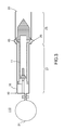
- the figure 1 represents a sectional diagram in an XY plane of a first embodiment of a projectile launch device 11 and a gun 18, as well as a sectional view of a section of the projectile 11 in a YZ plane perpendicular to the XY plane.
- the projectile 11 extends along an axis X between two ends 12, 13.
- the projectile 11 is intended to be positioned in the barrel 18 of substantially cylindrical shape of axis X.
- the projectile 11 comprises a hollow portion 14 at its center s opening on a first 12 of the two ends of the projectile 11, for receiving a compressed fluid.
- the projectile 11 comprises a plurality of vents 15 passing through the projectile 11 from the hollow portion 14 substantially perpendicular to the axis X and with a substantially radial outlet intended to expel the compressed fluid substantially tangentially to the projectile 11.
- the compressed fluid may be a compressed gas.
- the compressed fluid enters the projectile 11 through the hollow portion 14 and extends tangentially to the section of the projectile 11 through the vents 15.
- the output of the fluid compressed tangentially to the section of the projectile 11 through the vents 15 creates a torque on the projectile which turns it on itself. In other words, the projectile 11 is rotated on itself, around the axis X.
- the compressed fluid Upon entering the projectile 11, the compressed fluid causes an increase in the pressure in the projectile. This increase in pressure generates a translation of the projectile along the axis X, which allows projection of the projectile 11. At the same time, the pressure of the fluid and the flow of the fluid in the vents generate a rotation of the projectile on it -even.
- the hollow portion 14 and the vents 15 of the projectile 11 allow both a translational movement along the X axis and a rotational movement about the X axis of the projectile 11. cut in the YZ plane of the figure 1 the projectile 11 comprises 3 vents. For a good rotation of the projectile 11, it takes at least two vents, but it is also possible to have three or more.
- the projectile 11 comprises a head 16 and a body 17.
- the head 16 of the projectile 11 extends from a second 13 of the two ends of the projectile 11 to the plurality of vents 15.
- the body 17 of the projectile 11 extends from the head 16 to the first end 12 of the projectile 11.
- the barrel 18 has two ends 19, 20, in which the projectile 11 is positioned, a first 19 of the two ends of the barrel 18 allowing the entry of the compressed fluid into the barrel 18, a second 20 of the two ends allowing the exit of the projectile 11.
- the device 10 for rotating the projectile 11 comprises a reservoir 21 of compressed fluid connected to the first end 19 of the barrel 18 in which the projectile 11 is located, so as to feed the projectile 11 compressed fluid.
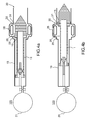
- the Figures 2a and 2b represent a diagram, in section in the XY plane, of a second embodiment of a device 100 for launching the projectile 11.
- the barrel 18 comprises a first 23 of two elements 23, 24 of helical connection.
- the projectile 11 comprises a second 24 of two elements 23, 24 of helical connection fixed in the hollow portion 14 of the projectile 11, the first 23 and the second 24 helical connecting elements forming a combined movement mechanism 22, so as to generate simultaneously a rotation about the axis X and translation along the axis X of the projectile 11 relative to the barrel 18.
- the mechanism 22 of combined movement may be a screw-nut assembly, or preferably an assembly with a ball screw or screw rollers for limiting the friction between the two connecting elements 23, 24.
- the pressure of the compressed fluid pushes the projectile 11 outside the barrel 18.
- the vents 15 with a substantially radial output make it possible to generate a rotational movement about the axis X of the projectile 11.
- the projectile maintains its trajectory in its axis, trajectory along the axis X, it is desirable that it be well accelerated in rotation around its X axis so that it always stays in the same direction.
- One of the two elements 23 or 24 is similar to a threaded rod and the other of the two elements 23 or 24 is similar to a nut.
- the projectile 11 According to the number N of steps on which the nut is engaged on the threaded rod, the projectile 11 will perform the same number N of turns on itself, thus a movement of N rotations, as shown in FIG. figure 2a , before being released in translation and to be ejected, as shown on the figure 2b .
- the linking mechanism 22 thus allows the projectile 11 to acquire greater angular acceleration around the X axis before accelerating in translation along the X axis.
- the figure 3 represents a diagram, in section in the XY plane, of a third embodiment of a device 110 for launching the projectile 11 comprising the barrel 18.
- the barrel 18 comprises a first substantially radial opening 25. This substantially radial opening 25 allows compressed fluid to exit the barrel 18 after it flows through the projectile 11.
- the barrel 18 comprises a head 26 and a body 27, the head 26 of the barrel 18 extending from the second 20 of the two ends of the barrel 18 to the opening 25, the body 27 of the barrel 18 extending from the head 26 of the barrel 18 to the first 19 of both ends of the barrel 18.
- the diameter of the body 27 of the barrel 18 is smaller than the diameter of the head 26 of the barrel 18.
- the diameter of the body 17 of the projectile 11 is smaller than the diameter of the head 16 of the projectile 11.
- the diameter of the body 17 of the projectile 11 is smaller than the diameter of the body 27 of the barrel 18 and the diameter of the head 16 of the projectile 11 is smaller than the diameter of the head 26 of the barrel 18.
- the diameter of the head 26 of the barrel 28 is substantially greater than the diameter of the head 16 of the projectile 11
- the diameter of the body 27 of the barrel 18 is substantially greater than the diameter of the body 17 of the projectile 11.
- This difference in diameters between the bodies and the heads respectively constitutes a guidance system of the projectile 11.
- the bodies corresponding to a first diameter smaller than a second diameter corresponding to that of the heads during its ejection, the projectile 11 is simultaneously releases at the level of the body and the head. This configuration thus avoids any disturbance in the trajectory of the projectile 11 which could be generated by the vibrations at the gun.
- the Figures 4a and 4b represent a diagram, in section in the XY plane, of a fourth embodiment of a device 120 for launching the projectile 11 comprising the barrel 18.
- the barrel 18 comprises a discharge conduit 28 having two ends 29, 30.
- the barrel 18 comprises a second opening 31 between the first opening 25 of the barrel 18 and the second 20 of the two ends of the barrel 18.
- a first 29 of the two ends of the discharge duct 28 is connected to the first opening 25 of the barrel 18 and a second 30 of the two ends of the exhaust duct 28 is connected to the second opening 31 of the barrel 18.
- the compressed fluid having a certain pressure and a certain flow rate must, after passing through the projectile 11, be evacuated from the barrel 18 As explained previously with the figure 3 the compressed fluid can simply be discharged through the radial opening 25 of the barrel 18. In this case, the compressed fluid is released to the outside (space, atmosphere, ie in the place of use of the spinning device of the projectile). It is also possible to use the evacuation of the compressed fluid to generate an aerodynamic effect on the projectile 11, as shown in FIGS. Figures 4a and 4b . On the figure 4a the projectile 11 is in a phase of angular acceleration.
- the combined movement mechanism 22 promotes the rotational acceleration of the projectile 11 and the radial opening 25 is substantially opposite to at least one vent 15.
- the compressed fluid exits the projectile 11 through the vent, generates a torque on the projectile 11 and rotates on itself.
- the compressed fluid then enters the exhaust duct 28 through the first end 29 (i.e. through the radial opening 25) and exits the exhaust duct 28 through the second end 30 (ie ie the second opening 31).
- the connecting elements 23, 24 of the mechanism 22 of combined movement being released from each other, that is to say the projectile 11 having acquired a sufficient angular acceleration, the projectile 11 moves towards the end 20 of the barrel 18.
- the vents 15 are then in vis-à-vis the second end 30 of the discharge conduit 28.
- the compressed fluid then enters the exhaust pipe 28 through the second end 30 and spring of the exhaust duct 28 through the radial opening 25 at the the first end 29 of the discharge duct 28.
- the flow of the compressed fluid to the body 27 of the barrel 18 will generate an increase in pressure in the body 27 of the barrel 18 and thus generate an additional force on the projectile according to the invention.
- X axis promoting acceleration in translation along the X axis of the projectile 11.
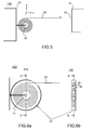
- the figure 5 represents a diagram, in section in the XY plane, of a first embodiment of a linking device 130 comprising a first object 40, a second object 41.
- the connecting device 130 comprises a first blade 42, able to pass a configuration wound around an axis Z around a support 43 fixed to the first object 40 to a configuration deployed along an axis X substantially perpendicular to the axis Z, the blade 42 having an end 44 intended to come into contact with the second object 41, so as to bind the first object 40 and the second object 41.
- a blade is wound and unrolled easily, with a minimum size in rolled configuration, because wrapped around the Z axis and substantially in the XY plane, which prevents the blade from becoming entangled. Nevertheless, it is also possible to consider a cable or rope instead of the blade, the cable or the rope, just like the blade 42, being able to pass from a configuration wrapped around the Z axis around the fixed support 43 to the first object 40 to a deployed configuration along the X axis.
- the Figures 6a and 6b represent a diagram, in section in the XY plane, of a second embodiment of the connecting device 130.
- the connecting device 130 comprises a first 45 and a second 46 flanges positioned substantially parallel to the XY plane, on the one hand and on the other. another of the first blade 42, and a cover 47 positioned around the first blade 42.
- the two flanges 45, 46 allow the blade 42 not to leave its winding when the blade 42 is unwound.
- the cover 47 also prevents the blade 42 from unfolding too much. Indeed, it is sometimes necessary to have a certain length of blade 42 quickly available to come into contact with the second object 41 or tow.
- the Figures 7a and 7b represent a diagram, in section in the XY plane, of a third embodiment of the connecting device.
- the connecting device 130 comprises a guiding device 48 of the first blade 42.
- the guiding device 48 may consist of two simple supports on either side of the blade 42 to guide it in its deployment.
- the simple supports may be pebbles forming a point connection on the blade 42 or fingers forming a longitudinal connection along the width of the blade 42.
- the connecting device 130 may comprise a cutting device 49 intended to cut the first blade 42. Such a cut may be necessary if it is no longer desired to come into contact with the second object or if it is no longer desired to tow it for reasons of safety or maneuverability.
- the cutting device may be a pyro shear or any other type of adapted shears.
- the figure 8 represents a diagram, in section in the XY plane, of a fourth embodiment of the connecting device 130.
- the connecting device 130 may further comprise a motor 50 having an output shaft 51 along the Z axis connected to the support 43, for winding and deploying the first blade 42.
- the figure 9 represents a diagram, in section in the XY plane, of a fifth embodiment of the connecting device 130.
- the connecting device 130 may comprise at least a second blade 52 superimposed on the first blade 42, able to pass from a configuration wound around the Z axis around the support 43 fixed to the first object 40 to a deployed configuration along the X axis substantially perpendicular to the Z axis, the blade 52 having an end 54 intended to come into contact with a third object (not shown), so as to bind the first object 40 and the third object.
- the blade 52 is superimposed on the blade 42.
- a third blade 53 can be wound around the support 43 by being superimposed on the blades 42 and 52.
- the connecting device 130 may comprise four or more blades superimposed between them and making it possible to link a fifth object, or more, to the first object 40.
- the figure 10 represents a diagram, in section in the XY plane, of a fifth embodiment of a device 140 for launching a projectile by compressed fluid according to the invention comprising the barrel 18, a tank 21 of compressed fluid connected to the first 19 of the two ends of the barrel 18.
- the launch device 140 comprises a connecting device 130 described above, the projectile 11 then being the second object 41.
- the support 43 is fixed to the device 140.
- the end 44 of the first blade 42 is connected to the second object, that is to the projectile 11 by a connecting element 55.
- the connecting element 55 is a mechanical component allowing the rotation of the projectile 11 around the X axis. act of a ball bearing allowing rotation around the axis X of the projectile 11.
- the support 43 is fixed in the barrel 18.
- the support 43 is fixed near the first 19 of the two ends of the barrel 18
- the d link device 130 is positioned in a rear portion of the barrel 18, which is the inlet of the compressed fluid.
- the compressed fluid from the reservoir 21 occupies the rear portion of the barrel 18.
- the compressed fluid then enters the barrel 18 at its end 19 and then enters the hollow portion 14 of the projectile 11 to emerge through the vents 15, so as to generate a rotational movement of the projectile 11 on itself and a translation of the projectile along the axis X.
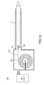
- the figures 11 a and 11b show a diagram, in section in the XY plane, of two embodiments of the connecting device 130.
- the connecting device 130 is positioned in the gun 18.
- the end 44 of the blade 42 is fixed to the projectile 11 by the connecting element 55 (not shown in these figures).
- the first object 40 is the barrel 18, the second object 41 is the projectile 11.
- the blade 42 while being attached to the projectile 11, will not disturb its trajectory once the projectile 11 will no longer be in the barrel 18.
- the connection of the blade 42 to the projectile being in the barrel 18, no leakage of fluid, and therefore pressure, can take place.
- the figure 12 represents a diagram, in section in the XY plane, of a second embodiment of the device 140 for launching a projectile 11 including a connecting device 130 according to the invention. All elements of the figure 12 are identical to the elements of the figure 11 b. This embodiment makes it possible to visualize the connecting element 55 of the end 44 of the blade 42 and of the projectile 11, as mentioned above with the figures 11 a and 11 b.
Abstract
La présente invention concerne un dispositif de lancement (140) par fluide comprimé comprenant : ¢ un projectile (11), ¢ un canon (18) ayant deux extrémités, le projectile (11) étant positionné à l'intérieur du canon (18), une première des deux extrémités permettant l'entrée du fluide comprimé dans le canon (18), une seconde des deux extrémités permettant la sortie du projectile, ¢ un réservoir de fluide (21) comprimé relié à la première des deux extrémités du canon (18). Selon l'invention, il comprend un dispositif de liaison comprenant une première lame, apte à passer d'une configuration enroulée autour d'un axe Z autour d'un support à une configuration déployée selon un axe X sensiblement perpendiculaire à l'axe Z, la lame ayant une extrémité fixée au projectile (11), et en ce que le support est fixé dans le canon (18).The present invention relates to a launch device (140) by compressed fluid comprising: € ¢ a projectile (11), € ¢ a barrel (18) having two ends, the projectile (11) being positioned inside the barrel (18), a first of the two ends allowing the entry of the compressed fluid in the barrel (18), a second of two ends allowing the exit of the projectile, € ¢ a reservoir of compressed fluid (21) connected to the first of the two ends of the barrel (18). According to the invention, it comprises a connecting device comprising a first blade, able to switch from a configuration wound around a Z axis around a support to a configuration deployed along an X axis substantially perpendicular to the Z axis. , the blade having one end fixed to the projectile (11), and in that the holder is fixed in the barrel (18).
Description
La présente invention concerne un dispositif de lancement d'un projectile par fluide comprimé. L'invention s'applique notamment dans le domaine spatial.The present invention relates to a device for launching a projectile by compressed fluid. The invention applies in particular in the spatial field.
Le nombre de débris spatiaux, de taille plus ou moins importante, est en constante augmentation. L'augmentation des débris spatiaux entraîne une augmentation du risque de collisions entre satellites et/ou avec une station spatiale. Certains débris sont jugés critiques à cause de leur taille et/ou de leur positionnement sur des zones appelées zones à risques, par exemple une orbite utile. On peut citer l'exemple d'un satellite en déperdition, des étages de fusée, pouvant être positionnés sur une orbite utile. La désorbitation de tels débris devient urgente pour les écarter de l'orbite utile. Se pose alors la question de savoir comment enlever ces débris pour dépolluer l'espace d'une façon efficace et sûre. En effet, il faut prévoir un appareillage et des manoeuvres fiables pour enlever les débris sous peine de générer des collisions non souhaitées et ainsi encore plus de débris.The number of space debris, larger or smaller, is constantly increasing. The increase in space debris increases the risk of collisions between satellites and / or with a space station. Some debris is considered critical because of its size and / or its positioning on areas called risk areas, such as a useful orbit. One example is a lost satellite, rocket stages, which can be positioned in a useful orbit. The deorbitation of such debris becomes urgent to remove them from the useful orbit. This raises the question of how to remove these debris to clean up the space in an efficient and safe way. Indeed, it is necessary to provide equipment and reliable maneuvers to remove debris under penalty of generating unwanted collisions and thus more debris.
Différentes solutions ont été suggérées. Parmi elles, on peut citer un bras articulé pour saisir les débris, un gigantesque filet ou un camion robot destinés à capturer les débris et à les ramener sur Terre ou à les parquer sur une orbite dite de parquage, loin des orbites utiles. Ces solutions sont coûteuses et difficiles à mettre en oeuvre.Different solutions have been suggested. Among them is an articulated arm to capture debris, a gigantic net or a robotic truck designed to capture debris and bring it back to Earth or park it in a so-called parcel orbit, far from useful orbits. These solutions are expensive and difficult to implement.
Une autre solution consiste à harponner l'objet cible considéré, à savoir le débris, pour le tracter hors de la zone à risque. Un problème majeur concerne la stabilité du harpon. En effet, l'atmosphère terrestre, que l'on peut considérer comme un milieu visqueux, engendre une résistance de l'air. Au contraire, dans l'espace, c'est-à-dire dans un vide presque parfait, un objet qui y évolue s'affranchit presque totalement de la résistance de l'air. Il en résulte qu'il n'y a pas d'effet aérodynamique sur cet objet. Autrement dit, dans le vide, on ne peut pas compter sur les effets aérodynamiques pour maintenir l'orientation du harpon dans l'axe de sa trajectoire. Une fois lancé, le harpon, maintenu généralement par un câble, ne se dirige alors plus dans la direction souhaitée vers l'objet cible. Il faut donc prendre en compte des contraintes supplémentaires liées au domaine spatial pour la conception de la solution du dispositif destiné à harponner l'objet cible. De plus, le lien entre le harpon et l'objet cible (c'est-à-dire le débris) peut créer des perturbations de la trajectoire du harpon lors du déroulement du câble. Et le câble peut aussi s'emmêler lorsqu'il est en stocké.Another solution is to harpoon the target object in question, namely the debris, to pull it out of the risk zone. A major problem concerns the stability of the harpoon. In fact, the earth's atmosphere, which can be considered as a viscous medium, generates air resistance. On the contrary, in space, that is to say, in an almost perfect vacuum, an object that evolves there is almost totally free of the resistance of the air. As a result, there is no aerodynamic effect on this object. In other words, in a vacuum, we can not rely on the aerodynamic effects to maintain the orientation of the harpoon in the axis of its trajectory. Once launched, the harpoon, usually held by a cable, is no longer the desired direction towards the target object. It is therefore necessary to take into account additional constraints related to the spatial domain for the design of the solution of the device intended to harpoon the target object. In addition, the link between the harpoon and the target object (ie debris) can create disturbances to the harpoon trajectory during the unwinding of the cable. And the cable can also tangle when stored.
L'invention vise à pallier tout ou partie des problèmes cités plus haut en proposant un dispositif de lancement d'un projectile par fluide comprimé permettant au projectile de maintenir sa trajectoire selon son axe de visée, le projectile étant lié grâce à un dispositif de liaison ne générant pas de perturbations sur la trajectoire du projectile.The invention aims to overcome all or part of the problems mentioned above by proposing a device for launching a projectile by compressed fluid allowing the projectile to maintain its trajectory along its line of sight, the projectile being linked through a connecting device not generating disturbances on the trajectory of the projectile.
A cet effet, l'invention a pour objet un dispositif de lancement d'un projectile par fluide comprimé comprenant :
- un canon ayant deux extrémités, le projectile étant positionné à l'intérieur du canon, une première des deux extrémités permettant l'entrée du fluide comprimé dans le canon, une seconde des deux extrémités permettant la sortie du projectile,
- un réservoir de fluide comprimé relié à la première des deux extrémités du canon,
- a gun having two ends, the projectile being positioned inside the barrel, a first of the two ends allowing the entry of the compressed fluid into the barrel, a second of the two ends allowing the exit of the projectile,
- a reservoir of compressed fluid connected to the first of the two ends of the barrel,
Selon un mode de réalisation, l'extrémité de la première lame est liée au projectile par un élément de liaison, et l'élément de liaison est un composant mécanique permettant la rotation du projectile autour de l'axe X.According to one embodiment, the end of the first blade is linked to the projectile by a connecting element, and the connecting element is a mechanical component allowing the projectile to rotate about the X axis.
L'invention sera mieux comprise et d'autres avantages apparaîtront à la lecture de la description détaillée d'un mode de réalisation donné à titre d'exemple, description illustrée par le dessin joint dans lequel :
- la
figure 1 représente un schéma en coupe dans un plan XY d'un premier mode de réalisation d'un dispositif de lancement d'un projectile selon l'invention, ainsi qu'une vue en coupe d'une section du projectile dans un plan YZ perpendiculaire au plan XY, - les
figures 2a et 2b représentent un schéma, en coupe dans le plan XY, d'un deuxième mode de réalisation d'un dispositif de lancement du projectile selon l'invention, - la
figure 3 représente un schéma, en coupe dans le plan XY, d'un troisième mode de réalisation d'un dispositif de lancement du projectile selon l'invention, - les
figures 4a et 4b représentent un schéma, en coupe dans le plan XY, d'un quatrième mode de réalisation d'un dispositif de lancement du projectile et comprenant le canon, - la
figure 5 représente un schéma, en coupe dans le plan XY, d'un premier mode de réalisation d'un dispositif de liaison destiné à lier un premier objet à un deuxième objet, - les
figures 6a et 6b représentent un schéma, en coupe dans le plan XY, d'un deuxième mode de réalisation du dispositif de liaison, - les
figures 7a et 7b représentent un schéma, en coupe dans le plan XY, d'un troisième mode de réalisation du dispositif de liaison, - la
figure 8 représente un schéma, en coupe dans le plan XY, d'un quatrième mode de réalisation du dispositif de liaison, - la
figure 9 représente un schéma, en coupe dans le plan XY, d'un cinquième mode de réalisation du dispositif de liaison, - la
figure 10 représente un schéma, en coupe dans le plan XY, d'un cinquième mode de réalisation du dispositif de lancement d'un projectile selon l'invention incluant un dispositif de liaison, - les
figures 11a et 11 b représentent un schéma, en coupe dans le plan XY, de deux modes de réalisation du dispositif de liaison, - la
figure 12 représente un schéma, en coupe dans le plan XY, d'un seconde mode de réalisation du dispositif de lancement d'un projectile incluant un dispositif de liaison selon l'invention.
- the
figure 1 represents a sectional diagram in an XY plane of a first embodiment of a launching device of a projectile according to the invention, as well as a sectional view of a section of the projectile in a plane YZ perpendicular to the XY plane, - the
Figures 2a and 2b represent a diagram, in section in the XY plane, of a second embodiment of a projectile launch device according to the invention, - the
figure 3 represents a diagram, in section in the XY plane, of a third embodiment of a launching device of the projectile according to the invention, - the
Figures 4a and 4b represent a diagram, in section in the XY plane, of a fourth embodiment of a launching device of the projectile and comprising the gun, - the
figure 5 represents a diagram, in section in the XY plane, of a first embodiment of a connection device for linking a first object to a second object, - the
Figures 6a and 6b represent a diagram, in section in the XY plane, of a second embodiment of the connection device, - the
Figures 7a and 7b represent a diagram, in section in the XY plane, of a third embodiment of the connecting device, - the
figure 8 represents a diagram, in section in the XY plane, of a fourth embodiment of the connection device, - the
figure 9 represents a diagram, in section in the XY plane, of a fifth embodiment of the connection device, - the
figure 10 represents a diagram, in section in the XY plane, of a fifth embodiment of the projectile launching device according to the invention including a connection device, - the
Figures 11a and 11b represent a diagram, in section in the XY plane, of two embodiments of the connection device, - the
figure 12 represents a diagram, in section in the XY plane, of a second embodiment of the projectile launch device including a connecting device according to the invention.
Par souci de clarté, les mêmes éléments porteront les mêmes repères dans les différentes figures.For the sake of clarity, the same elements will bear the same references in the different figures.
Il est à noter que l'invention est décrite dans le cadre d'une utilisation dans le domaine spatial. Néanmoins, elle trouve également application dans l'atmosphère terrestre, par exemple sur un navire afin de récupérer des débris dans l'eau ou flottant à la surface de l'eau ou sur le sol terrestre afin de tracter un objet.It should be noted that the invention is described in the context of use in the spatial field. Nevertheless, it also finds application in the Earth's atmosphere, for example on a ship in order to recover debris in the water or floating on the surface of the water or on the land floor in order to tow an object.
Et plus généralement, l'invention trouve application dans tous les cas de figure où un premier objet est lié à un deuxième objet.And more generally, the invention finds application in all cases where a first object is linked to a second object.
La
Le projectile 11 comprend une tête 16 et un corps 17. La tête 16 du projectile 11 s'étend d'une seconde 13 des deux extrémités du projectile 11 jusqu'à la pluralité d'évents 15. Le corps 17 du projectile 11 s'étend depuis la tête 16 jusqu'à la première extrémité 12 du projectile 11.The projectile 11 comprises a
Le canon 18 a deux extrémités 19, 20, dans lequel est positionné le projectile 11, une première 19 des deux extrémités du canon 18 permettant l'entrée du fluide comprimé dans le canon 18, une seconde 20 des deux extrémités permettant la sortie du projectile 11.The
Enfin, le dispositif 10 de mise en rotation du projectile 11 comprend un réservoir 21 de fluide comprimé relié à la première extrémité 19 du canon 18 dans lequel se trouve le projectile 11, de façon à alimenter le projectile 11 en fluide comprimé.Finally, the
Les
Il est à noter que sur les
La
Le canon 18 comprend une tête 26 et un corps 27, la tête 26 du canon 18 s'étendant de la seconde 20 des deux extrémités du canon 18 jusqu'à l'ouverture 25, le corps 27 du canon 18 s'étendant depuis la tête 26 du canon 18 jusqu'à la première 19 des deux extrémités du canon 18.The
On peut noter par ailleurs que le diamètre du corps 27 du canon 18 est inférieur au diamètre de la tête 26 du canon 18. De plus, le diamètre du corps 17 du projectile 11 est inférieur au diamètre de la tête 16 du projectile 11. Et le diamètre du corps 17 du projectile 11 est inférieur au diamètre du corps 27 du canon 18 et le diamètre de la tête 16 du projectile 11 est inférieur au diamètre de la tête 26 du canon 18.It may further be noted that the diameter of the
Autrement dit, le diamètre de la tête 26 du canon 28 est sensiblement supérieur au diamètre de la tête 16 du projectile 11, et le diamètre du corps 27 du canon 18 est sensiblement supérieur au diamètre du corps 17 du projectile 11.In other words, the diameter of the
Cette différence de diamètres entre les corps et les têtes respectivement constitue un système de guidage du projectile 11. En effet, les corps correspondant à un premier diamètre inférieur à un second diamètre correspondant à celui des têtes, lors de son éjection, le projectile 11 se libère simultanément au niveau du corps et de la tête. Cette configuration évite ainsi toute perturbation dans la trajectoire du projectile 11 qui pourrait être générée par les vibrations au niveau du canon.This difference in diameters between the bodies and the heads respectively constitutes a guidance system of the projectile 11. In fact, the bodies corresponding to a first diameter smaller than a second diameter corresponding to that of the heads, during its ejection, the projectile 11 is simultaneously releases at the level of the body and the head. This configuration thus avoids any disturbance in the trajectory of the projectile 11 which could be generated by the vibrations at the gun.
Les
La
Une lame s'enroule et se déroule facilement, avec un encombrement minimum en configuration enroulée, car enroulée autour de l'axe Z et sensiblement dans le plan XY, ce qui évite à la lame de s'emmêler. Néanmoins, on peut également considérer un câble ou une corde à la place de la lame, le câble ou la corde, tout comme la lame 42, étant apte à passer d'une configuration enroulée autour de l'axe Z autour du support 43 fixé au premier objet 40 à une configuration déployée selon l'axe X.A blade is wound and unrolled easily, with a minimum size in rolled configuration, because wrapped around the Z axis and substantially in the XY plane, which prevents the blade from becoming entangled. Nevertheless, it is also possible to consider a cable or rope instead of the blade, the cable or the rope, just like the
Les
Les
En outre, le dispositif de liaison 130 peut comprendre un dispositif de découpe 49 destiné à couper la première lame 42. Une telle découpe peut être nécessaire si on ne souhaite plus entrer en contact avec le deuxième objet ou si on ne souhaite plus le tracter pour des raisons de sécurité ou de manoeuvrabilité. Le dispositif de découpe peut être une cisaille pyro ou tout autre type de cisaille adaptée.In addition, the connecting
La
La
La
Les
La
Claims (1)
Applications Claiming Priority (1)
| Application Number | Priority Date | Filing Date | Title |
|---|---|---|---|
| FR1402779A FR3029615B1 (en) | 2014-12-05 | 2014-12-05 | DEVICE FOR LAUNCHING A PROJECTILE BY COMPRESSED FLUID |
Publications (2)
| Publication Number | Publication Date |
|---|---|
| EP3029410A1 true EP3029410A1 (en) | 2016-06-08 |
| EP3029410B1 EP3029410B1 (en) | 2017-06-07 |
Family
ID=53269515
Family Applications (1)
| Application Number | Title | Priority Date | Filing Date |
|---|---|---|---|
| EP15195558.0A Active EP3029410B1 (en) | 2014-12-05 | 2015-11-20 | Device for launching a projectile by compressed fluid |
Country Status (7)
| Country | Link |
|---|---|
| US (1) | US9546842B2 (en) |
| EP (1) | EP3029410B1 (en) |
| JP (1) | JP6866063B2 (en) |
| CN (1) | CN105674799B (en) |
| CA (1) | CA2913072C (en) |
| ES (1) | ES2639376T3 (en) |
| FR (1) | FR3029615B1 (en) |
Cited By (1)
| Publication number | Priority date | Publication date | Assignee | Title |
|---|---|---|---|---|
| WO2018087273A1 (en) * | 2016-11-10 | 2018-05-17 | Airbus Defence And Space Sas | Spacecraft comprising active attitude control means and passive attitude control means |
Families Citing this family (2)
| Publication number | Priority date | Publication date | Assignee | Title |
|---|---|---|---|---|
| JP2018114932A (en) * | 2017-01-20 | 2018-07-26 | 株式会社Ihi | Space debris capturing device and space debris removing device |
| DE102017106976A1 (en) * | 2017-03-31 | 2018-10-04 | Mobilshop GmbH | Apparatus and method for the pneumatic or gaseous catapulting of loose objects and production method thereof |
Citations (2)
| Publication number | Priority date | Publication date | Assignee | Title |
|---|---|---|---|---|
| US4110929A (en) * | 1977-12-07 | 1978-09-05 | Weigand Dwayne R | Fishing rod and projectile firing gun |
| US20040173197A1 (en) * | 2003-03-05 | 2004-09-09 | Moffitt Christopher Bruce | Pneumatic spear gun |
Family Cites Families (27)
| Publication number | Priority date | Publication date | Assignee | Title |
|---|---|---|---|---|
| US2090731A (en) * | 1934-02-13 | 1937-08-24 | Carl R Klein | Casting and harpooning gun |
| US2469533A (en) * | 1945-11-23 | 1949-05-10 | Hubert E Wellcome | Projection of twisted wires |
| US2703944A (en) * | 1953-12-29 | 1955-03-15 | Molyneux Cecil Patrick | Pneumatic harpoon gun and harpoon therefor |
| US2923286A (en) * | 1956-09-22 | 1960-02-02 | Draganti Dante | Pneumatic gun for subaquatic hunting |
| US3015182A (en) * | 1958-09-02 | 1962-01-02 | Robert H Darrow | Power casting device |
| US3153875A (en) * | 1961-08-21 | 1964-10-27 | Paul J Califano | Underwater spear gun |
| DE1564769B1 (en) * | 1965-12-06 | 1971-03-25 | Kunio Shimizu | Device for giving an electric shock to the human body |
| US3419991A (en) * | 1966-01-27 | 1969-01-07 | Donald J Sullivan | Pneumatic device |
| US3583087A (en) * | 1969-10-22 | 1971-06-08 | Harrington & Richardson Inc | Line throwing gun and cartridge |
| US3780720A (en) * | 1971-03-31 | 1973-12-25 | J Alderson | Compressed air spear projecting device |
| US3888033A (en) * | 1972-04-20 | 1975-06-10 | Raoul Fima | Underwater weapon |
| FR2298475A1 (en) * | 1975-01-24 | 1976-08-20 | France Etat | METHOD AND DEVICE FOR RECOVERING SUBMERSIBLE WRECKS |
| US4077349A (en) * | 1976-06-14 | 1978-03-07 | Paul William A | Line boy |
| US4155342A (en) * | 1977-11-02 | 1979-05-22 | Traweek Lowell E | Lasso gun |
| US5086749A (en) * | 1988-05-17 | 1992-02-11 | Glen Ekstrom | Arrow gun |
| US5029772A (en) * | 1989-05-31 | 1991-07-09 | Hughes Aircraft Company | Filament payout apparatus |
| US5174384A (en) * | 1990-10-02 | 1992-12-29 | Herman Walter W | Transport unit for fluid or solid materials or devices, and method |
| US5566858A (en) * | 1992-03-25 | 1996-10-22 | Ducker, Iii; Andrew L. | Underwater tool element kit |
| US5398587A (en) * | 1994-03-23 | 1995-03-21 | The United States Of America As Represented By The Secretary Of The Navy | Gas-propelled line deployment system |
| US5909000A (en) * | 1996-06-04 | 1999-06-01 | Rakov; Mikhail A. | System for shooting using compressed gas |
| EP1068129A1 (en) * | 1998-12-09 | 2001-01-17 | Halo Products, LLC | Linear medium pulling and retrieval system |
| US6244261B1 (en) * | 1999-05-21 | 2001-06-12 | David A. West, Jr. | Line installation tool |
| TW524305U (en) * | 2002-07-25 | 2003-03-11 | Hsien-Tung Chi | Rope structure of a rope throwing device |
| US6811503B2 (en) * | 2002-10-15 | 2004-11-02 | William May | Reconfigurable spear gun |
| US20090159065A1 (en) * | 2007-12-21 | 2009-06-25 | Christopher Bruce Moffitt | Pneumatic spear gun |
| US9546855B2 (en) * | 2012-05-30 | 2017-01-17 | Line Launcher Holdings Limited | Line delivery apparatus |
| FR3024227B1 (en) * | 2014-07-25 | 2018-02-09 | Thales | RECOVERABLE METER-RIBBON RECESSING METHOD FOR DEPLOYABLE STRUCTURE AND DEPLOYABLE METER-RIBBON STRUCTURE |
-
2014
- 2014-12-05 FR FR1402779A patent/FR3029615B1/en not_active Expired - Fee Related
-
2015
- 2015-11-20 EP EP15195558.0A patent/EP3029410B1/en active Active
- 2015-11-20 ES ES15195558.0T patent/ES2639376T3/en active Active
- 2015-11-24 CA CA2913072A patent/CA2913072C/en active Active
- 2015-11-26 JP JP2015230316A patent/JP6866063B2/en active Active
- 2015-12-02 CN CN201510873133.4A patent/CN105674799B/en active Active
- 2015-12-02 US US14/957,386 patent/US9546842B2/en active Active
Patent Citations (2)
| Publication number | Priority date | Publication date | Assignee | Title |
|---|---|---|---|---|
| US4110929A (en) * | 1977-12-07 | 1978-09-05 | Weigand Dwayne R | Fishing rod and projectile firing gun |
| US20040173197A1 (en) * | 2003-03-05 | 2004-09-09 | Moffitt Christopher Bruce | Pneumatic spear gun |
Cited By (2)
| Publication number | Priority date | Publication date | Assignee | Title |
|---|---|---|---|---|
| WO2018087273A1 (en) * | 2016-11-10 | 2018-05-17 | Airbus Defence And Space Sas | Spacecraft comprising active attitude control means and passive attitude control means |
| US10773832B2 (en) | 2016-11-10 | 2020-09-15 | Airbus Defence And Space Sas | Projectile intended for damping a spacecraft and corresponding space delivery vehicle |
Also Published As
| Publication number | Publication date |
|---|---|
| JP6866063B2 (en) | 2021-04-28 |
| CN105674799A (en) | 2016-06-15 |
| US9546842B2 (en) | 2017-01-17 |
| CN105674799B (en) | 2020-03-27 |
| FR3029615B1 (en) | 2018-01-05 |
| US20160161211A1 (en) | 2016-06-09 |
| CA2913072C (en) | 2022-09-20 |
| FR3029615A1 (en) | 2016-06-10 |
| JP2016109417A (en) | 2016-06-20 |
| EP3029410B1 (en) | 2017-06-07 |
| CA2913072A1 (en) | 2016-06-05 |
| ES2639376T3 (en) | 2017-10-26 |
Similar Documents
| Publication | Publication Date | Title |
|---|---|---|
| EP3029412B1 (en) | Projectile and cannon for receiving such a projectile | |
| EP3029410B1 (en) | Device for launching a projectile by compressed fluid | |
| FR2864613A1 (en) | DEVICE FOR DEPLOYING AND DRIVING GOVERNS OF A PROJECTILE | |
| FR2946740A1 (en) | APPARATUS FOR DEPLOYING WINGS AND APPARATUS FOR LAUNCHING A FLYING OBJECT COMPRISING THE SAME | |
| FR2743110A1 (en) | DEPLOYABLE DIVERGENT OF PROPELLER | |
| EP3227185B1 (en) | Device for connecting two objects by means of a tape spring | |
| FR2723911A1 (en) | UNLOCKABLE CONNECTION DEVICE BETWEEN TWO OBJECTS FOR USE IN PARTICULAR IN THE SPACE FIELD. | |
| EP0457683B1 (en) | Reel with captive cable and its use in a deployment regulator of an appendix of a spacecraft | |
| EP1376045B1 (en) | Adaptive device for a projectile fired from a launching tube | |
| EP3408172B1 (en) | Aircraft wing comprising a slat and a container for storing a flexible tube | |
| FR2919269A1 (en) | Arming rope mounting device for e.g. airplane, has belt winder with sheave comprising groove for receiving arming rope at winding stage and for storing rope and allowing extraction and deployment of winder during dropping of para-cargo | |
| EP0679861B1 (en) | Firing installation for wire guided ammunition from a mobile launcher | |
| FR2694537A1 (en) | Device for attaching a turbomachine to an aircraft structure. | |
| EP0653604B1 (en) | Stabilising for deployment device for a rocket type projectile | |
| CA2862968C (en) | Drive device for inserting a flexible object into a conduit | |
| FR2728229A1 (en) | BRAKING SHIELD FOR SPACE AND SATELLITE EQUIPMENT | |
| FR2714358A1 (en) | Electromechanical release mechanism for body secured to space vehicle | |
| FR2701108A1 (en) | Device slowing the fall of an optical fibre or a similar connecting member linking a missile to its launching platform | |
| FR3000229A1 (en) | Extraction device for extracting optical element in optical cable, has cutting element intended to be rotated relative to guide element via transmission element to cut optical element by trimming at location of cutting point |
Legal Events
| Date | Code | Title | Description |
|---|---|---|---|
| PUAI | Public reference made under article 153(3) epc to a published international application that has entered the european phase |
Free format text: ORIGINAL CODE: 0009012 |
|
| AK | Designated contracting states |
Kind code of ref document: A1 Designated state(s): AL AT BE BG CH CY CZ DE DK EE ES FI FR GB GR HR HU IE IS IT LI LT LU LV MC MK MT NL NO PL PT RO RS SE SI SK SM TR |
|
| AX | Request for extension of the european patent |
Extension state: BA ME |
|
| 17P | Request for examination filed |
Effective date: 20161207 |
|
| RBV | Designated contracting states (corrected) |
Designated state(s): AL AT BE BG CH CY CZ DE DK EE ES FI FR GB GR HR HU IE IS IT LI LT LU LV MC MK MT NL NO PL PT RO RS SE SI SK SM TR |
|
| GRAP | Despatch of communication of intention to grant a patent |
Free format text: ORIGINAL CODE: EPIDOSNIGR1 |
|
| RIC1 | Information provided on ipc code assigned before grant |
Ipc: F41B 11/83 20130101AFI20170119BHEP Ipc: F41G 7/32 20060101ALI20170119BHEP |
|
| INTG | Intention to grant announced |
Effective date: 20170207 |
|
| GRAS | Grant fee paid |
Free format text: ORIGINAL CODE: EPIDOSNIGR3 |
|
| AK | Designated contracting states |
Kind code of ref document: B1 Designated state(s): AL AT BE BG CH CY CZ DE DK EE ES FI FR GB GR HR HU IE IS IT LI LT LU LV MC MK MT NL NO PL PT RO RS SE SI SK SM TR |
|
| REG | Reference to a national code |
Ref country code: GB Ref legal event code: FG4D Free format text: NOT ENGLISH |
|
| GRAA | (expected) grant |
Free format text: ORIGINAL CODE: 0009210 |
|
| REG | Reference to a national code |
Ref country code: CH Ref legal event code: EP Ref country code: AT Ref legal event code: REF Ref document number: 899562 Country of ref document: AT Kind code of ref document: T Effective date: 20170615 |
|
| REG | Reference to a national code |
Ref country code: IE Ref legal event code: FG4D Free format text: LANGUAGE OF EP DOCUMENT: FRENCH |
|
| REG | Reference to a national code |
Ref country code: DE Ref legal event code: R096 Ref document number: 602015003004 Country of ref document: DE |
|
| REG | Reference to a national code |
Ref country code: NL Ref legal event code: FP |
|
| REG | Reference to a national code |
Ref country code: LT Ref legal event code: MG4D |
|
| REG | Reference to a national code |
Ref country code: ES Ref legal event code: FG2A Ref document number: 2639376 Country of ref document: ES Kind code of ref document: T3 Effective date: 20171026 Ref country code: FR Ref legal event code: PLFP Year of fee payment: 3 |
|
| PG25 | Lapsed in a contracting state [announced via postgrant information from national office to epo] |
Ref country code: NO Free format text: LAPSE BECAUSE OF FAILURE TO SUBMIT A TRANSLATION OF THE DESCRIPTION OR TO PAY THE FEE WITHIN THE PRESCRIBED TIME-LIMIT Effective date: 20170907 Ref country code: FI Free format text: LAPSE BECAUSE OF FAILURE TO SUBMIT A TRANSLATION OF THE DESCRIPTION OR TO PAY THE FEE WITHIN THE PRESCRIBED TIME-LIMIT Effective date: 20170607 Ref country code: GR Free format text: LAPSE BECAUSE OF FAILURE TO SUBMIT A TRANSLATION OF THE DESCRIPTION OR TO PAY THE FEE WITHIN THE PRESCRIBED TIME-LIMIT Effective date: 20170908 Ref country code: LT Free format text: LAPSE BECAUSE OF FAILURE TO SUBMIT A TRANSLATION OF THE DESCRIPTION OR TO PAY THE FEE WITHIN THE PRESCRIBED TIME-LIMIT Effective date: 20170607 Ref country code: HR Free format text: LAPSE BECAUSE OF FAILURE TO SUBMIT A TRANSLATION OF THE DESCRIPTION OR TO PAY THE FEE WITHIN THE PRESCRIBED TIME-LIMIT Effective date: 20170607 |
|
| REG | Reference to a national code |
Ref country code: AT Ref legal event code: MK05 Ref document number: 899562 Country of ref document: AT Kind code of ref document: T Effective date: 20170607 |
|
| PG25 | Lapsed in a contracting state [announced via postgrant information from national office to epo] |
Ref country code: BG Free format text: LAPSE BECAUSE OF FAILURE TO SUBMIT A TRANSLATION OF THE DESCRIPTION OR TO PAY THE FEE WITHIN THE PRESCRIBED TIME-LIMIT Effective date: 20170907 Ref country code: LV Free format text: LAPSE BECAUSE OF FAILURE TO SUBMIT A TRANSLATION OF THE DESCRIPTION OR TO PAY THE FEE WITHIN THE PRESCRIBED TIME-LIMIT Effective date: 20170607 Ref country code: SE Free format text: LAPSE BECAUSE OF FAILURE TO SUBMIT A TRANSLATION OF THE DESCRIPTION OR TO PAY THE FEE WITHIN THE PRESCRIBED TIME-LIMIT Effective date: 20170607 Ref country code: RS Free format text: LAPSE BECAUSE OF FAILURE TO SUBMIT A TRANSLATION OF THE DESCRIPTION OR TO PAY THE FEE WITHIN THE PRESCRIBED TIME-LIMIT Effective date: 20170607 |
|
| PG25 | Lapsed in a contracting state [announced via postgrant information from national office to epo] |
Ref country code: RO Free format text: LAPSE BECAUSE OF FAILURE TO SUBMIT A TRANSLATION OF THE DESCRIPTION OR TO PAY THE FEE WITHIN THE PRESCRIBED TIME-LIMIT Effective date: 20170607 Ref country code: EE Free format text: LAPSE BECAUSE OF FAILURE TO SUBMIT A TRANSLATION OF THE DESCRIPTION OR TO PAY THE FEE WITHIN THE PRESCRIBED TIME-LIMIT Effective date: 20170607 Ref country code: SK Free format text: LAPSE BECAUSE OF FAILURE TO SUBMIT A TRANSLATION OF THE DESCRIPTION OR TO PAY THE FEE WITHIN THE PRESCRIBED TIME-LIMIT Effective date: 20170607 Ref country code: CZ Free format text: LAPSE BECAUSE OF FAILURE TO SUBMIT A TRANSLATION OF THE DESCRIPTION OR TO PAY THE FEE WITHIN THE PRESCRIBED TIME-LIMIT Effective date: 20170607 Ref country code: AT Free format text: LAPSE BECAUSE OF FAILURE TO SUBMIT A TRANSLATION OF THE DESCRIPTION OR TO PAY THE FEE WITHIN THE PRESCRIBED TIME-LIMIT Effective date: 20170607 |
|
| PG25 | Lapsed in a contracting state [announced via postgrant information from national office to epo] |
Ref country code: SM Free format text: LAPSE BECAUSE OF FAILURE TO SUBMIT A TRANSLATION OF THE DESCRIPTION OR TO PAY THE FEE WITHIN THE PRESCRIBED TIME-LIMIT Effective date: 20170607 Ref country code: IS Free format text: LAPSE BECAUSE OF FAILURE TO SUBMIT A TRANSLATION OF THE DESCRIPTION OR TO PAY THE FEE WITHIN THE PRESCRIBED TIME-LIMIT Effective date: 20171007 Ref country code: PL Free format text: LAPSE BECAUSE OF FAILURE TO SUBMIT A TRANSLATION OF THE DESCRIPTION OR TO PAY THE FEE WITHIN THE PRESCRIBED TIME-LIMIT Effective date: 20170607 |
|
| REG | Reference to a national code |
Ref country code: DE Ref legal event code: R097 Ref document number: 602015003004 Country of ref document: DE |
|
| PLBE | No opposition filed within time limit |
Free format text: ORIGINAL CODE: 0009261 |
|
| STAA | Information on the status of an ep patent application or granted ep patent |
Free format text: STATUS: NO OPPOSITION FILED WITHIN TIME LIMIT |
|
| PG25 | Lapsed in a contracting state [announced via postgrant information from national office to epo] |
Ref country code: DK Free format text: LAPSE BECAUSE OF FAILURE TO SUBMIT A TRANSLATION OF THE DESCRIPTION OR TO PAY THE FEE WITHIN THE PRESCRIBED TIME-LIMIT Effective date: 20170607 |
|
| 26N | No opposition filed |
Effective date: 20180308 |
|
| PG25 | Lapsed in a contracting state [announced via postgrant information from national office to epo] |
Ref country code: SI Free format text: LAPSE BECAUSE OF FAILURE TO SUBMIT A TRANSLATION OF THE DESCRIPTION OR TO PAY THE FEE WITHIN THE PRESCRIBED TIME-LIMIT Effective date: 20170607 |
|
| PG25 | Lapsed in a contracting state [announced via postgrant information from national office to epo] |
Ref country code: MC Free format text: LAPSE BECAUSE OF FAILURE TO SUBMIT A TRANSLATION OF THE DESCRIPTION OR TO PAY THE FEE WITHIN THE PRESCRIBED TIME-LIMIT Effective date: 20170607 |
|
| PG25 | Lapsed in a contracting state [announced via postgrant information from national office to epo] |
Ref country code: LU Free format text: LAPSE BECAUSE OF NON-PAYMENT OF DUE FEES Effective date: 20171120 |
|
| REG | Reference to a national code |
Ref country code: BE Ref legal event code: MM Effective date: 20171130 |
|
| REG | Reference to a national code |
Ref country code: IE Ref legal event code: MM4A |
|
| PG25 | Lapsed in a contracting state [announced via postgrant information from national office to epo] |
Ref country code: MT Free format text: LAPSE BECAUSE OF FAILURE TO SUBMIT A TRANSLATION OF THE DESCRIPTION OR TO PAY THE FEE WITHIN THE PRESCRIBED TIME-LIMIT Effective date: 20170607 |
|
| REG | Reference to a national code |
Ref country code: FR Ref legal event code: PLFP Year of fee payment: 4 |
|
| PG25 | Lapsed in a contracting state [announced via postgrant information from national office to epo] |
Ref country code: IE Free format text: LAPSE BECAUSE OF NON-PAYMENT OF DUE FEES Effective date: 20171120 |
|
| PG25 | Lapsed in a contracting state [announced via postgrant information from national office to epo] |
Ref country code: BE Free format text: LAPSE BECAUSE OF NON-PAYMENT OF DUE FEES Effective date: 20171130 |
|
| PG25 | Lapsed in a contracting state [announced via postgrant information from national office to epo] |
Ref country code: HU Free format text: LAPSE BECAUSE OF FAILURE TO SUBMIT A TRANSLATION OF THE DESCRIPTION OR TO PAY THE FEE WITHIN THE PRESCRIBED TIME-LIMIT; INVALID AB INITIO Effective date: 20151120 |
|
| REG | Reference to a national code |
Ref country code: CH Ref legal event code: PL |
|
| PG25 | Lapsed in a contracting state [announced via postgrant information from national office to epo] |
Ref country code: CH Free format text: LAPSE BECAUSE OF NON-PAYMENT OF DUE FEES Effective date: 20181130 Ref country code: LI Free format text: LAPSE BECAUSE OF NON-PAYMENT OF DUE FEES Effective date: 20181130 |
|
| PG25 | Lapsed in a contracting state [announced via postgrant information from national office to epo] |
Ref country code: CY Free format text: LAPSE BECAUSE OF FAILURE TO SUBMIT A TRANSLATION OF THE DESCRIPTION OR TO PAY THE FEE WITHIN THE PRESCRIBED TIME-LIMIT Effective date: 20170607 |
|
| PG25 | Lapsed in a contracting state [announced via postgrant information from national office to epo] |
Ref country code: MK Free format text: LAPSE BECAUSE OF FAILURE TO SUBMIT A TRANSLATION OF THE DESCRIPTION OR TO PAY THE FEE WITHIN THE PRESCRIBED TIME-LIMIT Effective date: 20170607 |
|
| PG25 | Lapsed in a contracting state [announced via postgrant information from national office to epo] |
Ref country code: TR Free format text: LAPSE BECAUSE OF FAILURE TO SUBMIT A TRANSLATION OF THE DESCRIPTION OR TO PAY THE FEE WITHIN THE PRESCRIBED TIME-LIMIT Effective date: 20170607 |
|
| PG25 | Lapsed in a contracting state [announced via postgrant information from national office to epo] |
Ref country code: PT Free format text: LAPSE BECAUSE OF FAILURE TO SUBMIT A TRANSLATION OF THE DESCRIPTION OR TO PAY THE FEE WITHIN THE PRESCRIBED TIME-LIMIT Effective date: 20170607 |
|
| PG25 | Lapsed in a contracting state [announced via postgrant information from national office to epo] |
Ref country code: AL Free format text: LAPSE BECAUSE OF FAILURE TO SUBMIT A TRANSLATION OF THE DESCRIPTION OR TO PAY THE FEE WITHIN THE PRESCRIBED TIME-LIMIT Effective date: 20170607 |
|
| PGFP | Annual fee paid to national office [announced via postgrant information from national office to epo] |
Ref country code: NL Payment date: 20231026 Year of fee payment: 9 |
|
| PGFP | Annual fee paid to national office [announced via postgrant information from national office to epo] |
Ref country code: GB Payment date: 20231019 Year of fee payment: 9 |
|
| PGFP | Annual fee paid to national office [announced via postgrant information from national office to epo] |
Ref country code: ES Payment date: 20231211 Year of fee payment: 9 |
|
| PGFP | Annual fee paid to national office [announced via postgrant information from national office to epo] |
Ref country code: IT Payment date: 20231026 Year of fee payment: 9 Ref country code: FR Payment date: 20231024 Year of fee payment: 9 Ref country code: DE Payment date: 20231017 Year of fee payment: 9 |