EP3037062A1 - Catheter having a guidewire channel - Google Patents
Catheter having a guidewire channel Download PDFInfo
- Publication number
- EP3037062A1 EP3037062A1 EP16153699.0A EP16153699A EP3037062A1 EP 3037062 A1 EP3037062 A1 EP 3037062A1 EP 16153699 A EP16153699 A EP 16153699A EP 3037062 A1 EP3037062 A1 EP 3037062A1
- Authority
- EP
- European Patent Office
- Prior art keywords
- catheter
- channel
- guidewire
- opening
- proximal end
- Prior art date
- Legal status (The legal status is an assumption and is not a legal conclusion. Google has not performed a legal analysis and makes no representation as to the accuracy of the status listed.)
- Withdrawn
Links
Images


Classifications
-
- A—HUMAN NECESSITIES
- A61—MEDICAL OR VETERINARY SCIENCE; HYGIENE
- A61F—FILTERS IMPLANTABLE INTO BLOOD VESSELS; PROSTHESES; DEVICES PROVIDING PATENCY TO, OR PREVENTING COLLAPSING OF, TUBULAR STRUCTURES OF THE BODY, e.g. STENTS; ORTHOPAEDIC, NURSING OR CONTRACEPTIVE DEVICES; FOMENTATION; TREATMENT OR PROTECTION OF EYES OR EARS; BANDAGES, DRESSINGS OR ABSORBENT PADS; FIRST-AID KITS
- A61F2/00—Filters implantable into blood vessels; Prostheses, i.e. artificial substitutes or replacements for parts of the body; Appliances for connecting them with the body; Devices providing patency to, or preventing collapsing of, tubular structures of the body, e.g. stents
- A61F2/95—Instruments specially adapted for placement or removal of stents or stent-grafts
- A61F2/962—Instruments specially adapted for placement or removal of stents or stent-grafts having an outer sleeve
- A61F2/97—Instruments specially adapted for placement or removal of stents or stent-grafts having an outer sleeve the outer sleeve being splittable
-
- A—HUMAN NECESSITIES
- A61—MEDICAL OR VETERINARY SCIENCE; HYGIENE
- A61F—FILTERS IMPLANTABLE INTO BLOOD VESSELS; PROSTHESES; DEVICES PROVIDING PATENCY TO, OR PREVENTING COLLAPSING OF, TUBULAR STRUCTURES OF THE BODY, e.g. STENTS; ORTHOPAEDIC, NURSING OR CONTRACEPTIVE DEVICES; FOMENTATION; TREATMENT OR PROTECTION OF EYES OR EARS; BANDAGES, DRESSINGS OR ABSORBENT PADS; FIRST-AID KITS
- A61F2/00—Filters implantable into blood vessels; Prostheses, i.e. artificial substitutes or replacements for parts of the body; Appliances for connecting them with the body; Devices providing patency to, or preventing collapsing of, tubular structures of the body, e.g. stents
- A61F2/02—Prostheses implantable into the body
- A61F2/04—Hollow or tubular parts of organs, e.g. bladders, tracheae, bronchi or bile ducts
- A61F2/06—Blood vessels
- A61F2/07—Stent-grafts
-
- A—HUMAN NECESSITIES
- A61—MEDICAL OR VETERINARY SCIENCE; HYGIENE
- A61F—FILTERS IMPLANTABLE INTO BLOOD VESSELS; PROSTHESES; DEVICES PROVIDING PATENCY TO, OR PREVENTING COLLAPSING OF, TUBULAR STRUCTURES OF THE BODY, e.g. STENTS; ORTHOPAEDIC, NURSING OR CONTRACEPTIVE DEVICES; FOMENTATION; TREATMENT OR PROTECTION OF EYES OR EARS; BANDAGES, DRESSINGS OR ABSORBENT PADS; FIRST-AID KITS
- A61F2/00—Filters implantable into blood vessels; Prostheses, i.e. artificial substitutes or replacements for parts of the body; Appliances for connecting them with the body; Devices providing patency to, or preventing collapsing of, tubular structures of the body, e.g. stents
- A61F2/95—Instruments specially adapted for placement or removal of stents or stent-grafts
- A61F2/954—Instruments specially adapted for placement or removal of stents or stent-grafts for placing stents or stent-grafts in a bifurcation
-
- A—HUMAN NECESSITIES
- A61—MEDICAL OR VETERINARY SCIENCE; HYGIENE
- A61F—FILTERS IMPLANTABLE INTO BLOOD VESSELS; PROSTHESES; DEVICES PROVIDING PATENCY TO, OR PREVENTING COLLAPSING OF, TUBULAR STRUCTURES OF THE BODY, e.g. STENTS; ORTHOPAEDIC, NURSING OR CONTRACEPTIVE DEVICES; FOMENTATION; TREATMENT OR PROTECTION OF EYES OR EARS; BANDAGES, DRESSINGS OR ABSORBENT PADS; FIRST-AID KITS
- A61F2/00—Filters implantable into blood vessels; Prostheses, i.e. artificial substitutes or replacements for parts of the body; Appliances for connecting them with the body; Devices providing patency to, or preventing collapsing of, tubular structures of the body, e.g. stents
- A61F2/82—Devices providing patency to, or preventing collapsing of, tubular structures of the body, e.g. stents
- A61F2/856—Single tubular stent with a side portal passage
-
- A—HUMAN NECESSITIES
- A61—MEDICAL OR VETERINARY SCIENCE; HYGIENE
- A61F—FILTERS IMPLANTABLE INTO BLOOD VESSELS; PROSTHESES; DEVICES PROVIDING PATENCY TO, OR PREVENTING COLLAPSING OF, TUBULAR STRUCTURES OF THE BODY, e.g. STENTS; ORTHOPAEDIC, NURSING OR CONTRACEPTIVE DEVICES; FOMENTATION; TREATMENT OR PROTECTION OF EYES OR EARS; BANDAGES, DRESSINGS OR ABSORBENT PADS; FIRST-AID KITS
- A61F2/00—Filters implantable into blood vessels; Prostheses, i.e. artificial substitutes or replacements for parts of the body; Appliances for connecting them with the body; Devices providing patency to, or preventing collapsing of, tubular structures of the body, e.g. stents
- A61F2/02—Prostheses implantable into the body
- A61F2/04—Hollow or tubular parts of organs, e.g. bladders, tracheae, bronchi or bile ducts
- A61F2/06—Blood vessels
- A61F2002/061—Blood vessels provided with means for allowing access to secondary lumens
-
- A—HUMAN NECESSITIES
- A61—MEDICAL OR VETERINARY SCIENCE; HYGIENE
- A61F—FILTERS IMPLANTABLE INTO BLOOD VESSELS; PROSTHESES; DEVICES PROVIDING PATENCY TO, OR PREVENTING COLLAPSING OF, TUBULAR STRUCTURES OF THE BODY, e.g. STENTS; ORTHOPAEDIC, NURSING OR CONTRACEPTIVE DEVICES; FOMENTATION; TREATMENT OR PROTECTION OF EYES OR EARS; BANDAGES, DRESSINGS OR ABSORBENT PADS; FIRST-AID KITS
- A61F2/00—Filters implantable into blood vessels; Prostheses, i.e. artificial substitutes or replacements for parts of the body; Appliances for connecting them with the body; Devices providing patency to, or preventing collapsing of, tubular structures of the body, e.g. stents
- A61F2/02—Prostheses implantable into the body
- A61F2/04—Hollow or tubular parts of organs, e.g. bladders, tracheae, bronchi or bile ducts
- A61F2/06—Blood vessels
- A61F2002/065—Y-shaped blood vessels
-
- A—HUMAN NECESSITIES
- A61—MEDICAL OR VETERINARY SCIENCE; HYGIENE
- A61F—FILTERS IMPLANTABLE INTO BLOOD VESSELS; PROSTHESES; DEVICES PROVIDING PATENCY TO, OR PREVENTING COLLAPSING OF, TUBULAR STRUCTURES OF THE BODY, e.g. STENTS; ORTHOPAEDIC, NURSING OR CONTRACEPTIVE DEVICES; FOMENTATION; TREATMENT OR PROTECTION OF EYES OR EARS; BANDAGES, DRESSINGS OR ABSORBENT PADS; FIRST-AID KITS
- A61F2/00—Filters implantable into blood vessels; Prostheses, i.e. artificial substitutes or replacements for parts of the body; Appliances for connecting them with the body; Devices providing patency to, or preventing collapsing of, tubular structures of the body, e.g. stents
- A61F2/02—Prostheses implantable into the body
- A61F2/04—Hollow or tubular parts of organs, e.g. bladders, tracheae, bronchi or bile ducts
- A61F2/06—Blood vessels
- A61F2/07—Stent-grafts
- A61F2002/075—Stent-grafts the stent being loosely attached to the graft material, e.g. by stitching
-
- A—HUMAN NECESSITIES
- A61—MEDICAL OR VETERINARY SCIENCE; HYGIENE
- A61F—FILTERS IMPLANTABLE INTO BLOOD VESSELS; PROSTHESES; DEVICES PROVIDING PATENCY TO, OR PREVENTING COLLAPSING OF, TUBULAR STRUCTURES OF THE BODY, e.g. STENTS; ORTHOPAEDIC, NURSING OR CONTRACEPTIVE DEVICES; FOMENTATION; TREATMENT OR PROTECTION OF EYES OR EARS; BANDAGES, DRESSINGS OR ABSORBENT PADS; FIRST-AID KITS
- A61F2/00—Filters implantable into blood vessels; Prostheses, i.e. artificial substitutes or replacements for parts of the body; Appliances for connecting them with the body; Devices providing patency to, or preventing collapsing of, tubular structures of the body, e.g. stents
- A61F2/82—Devices providing patency to, or preventing collapsing of, tubular structures of the body, e.g. stents
- A61F2002/821—Ostial stents
-
- A—HUMAN NECESSITIES
- A61—MEDICAL OR VETERINARY SCIENCE; HYGIENE
- A61F—FILTERS IMPLANTABLE INTO BLOOD VESSELS; PROSTHESES; DEVICES PROVIDING PATENCY TO, OR PREVENTING COLLAPSING OF, TUBULAR STRUCTURES OF THE BODY, e.g. STENTS; ORTHOPAEDIC, NURSING OR CONTRACEPTIVE DEVICES; FOMENTATION; TREATMENT OR PROTECTION OF EYES OR EARS; BANDAGES, DRESSINGS OR ABSORBENT PADS; FIRST-AID KITS
- A61F2250/00—Special features of prostheses classified in groups A61F2/00 - A61F2/26 or A61F2/82 or A61F9/00 or A61F11/00 or subgroups thereof
- A61F2250/0058—Additional features; Implant or prostheses properties not otherwise provided for
- A61F2250/0059—Additional features; Implant or prostheses properties not otherwise provided for temporary
Definitions
- the present invention relates to catheters useful for delivering expandable endoluminal prostheses.
- the catheters are particularly suited for use in delivering expandable endoluminal prostheses to bifurcated regions of body lumens.
- Stents or stent grafts are examples of expandable endoluminal prosthetic devices which are used to maintain, open or dilate stenotic lesions in body lumens or to cover and repair an aneurysm.
- Vascular disease may occur at a branch or bifurcation in a vessel. Placement and deployment of these prosthetic devices at bifurcations can often be problematic.
- One current technique is to initially deploy across an aneurysm a main body prosthetic device having a side wall opening. The side wall opening is aligned with the side branch ostium. A second prosthetic device is then deployed through the main body prosthetic device side wall opening and into the side branch vessel. Procedural complications are often encountered while practicing this technique.
- Alternate procedures for treating bifurcated vessels place the guidewires prior to the device deployments. After the main body prosthetic device is deployed it is advantageous to then remove the main body delivery catheter prior to the delivery of the side branch prosthetic device.
- Typical delivery systems incorporate guidewires that are contained or captured within the delivery catheter. The catheter removal therefore requires careful management of the side branch guidewire to prevent its dislodgement during the removal of the delivery catheter.
- An aspect of the invention includes a catheter comprising:
- the catheter body can include a guidewire lumen extending from the catheter body distal end to a point proximal thereto.
- an expandable prosthesis can be loaded on the distal end of the catheter, with the guidewire channel proximal end extending proximally from the expandable prosthesis and the guidewire channel distal end extending out of a side opening in the expandable prosthesis.
- a further aspect of the invention provides methods for delivering an expandable prosthesis using the catheter of the invention that overcome the drawbacks relating to conventional devices and delivery methods.
- An aspect of the invention includes a catheter comprising:
- the catheter body can include a guidewire lumen extending from the catheter body distal end to a point proximal thereto.
- an expandable prosthesis can be loaded on the distal end of the catheter, with the guidewire channel proximal end extending proximally from the expandable prosthesis and the guidewire channel distal end extending out of a side opening in the expandable prosthesis.
- a further aspect of the invention provides methods for delivery of an expandable prosthesis that overcome the drawbacks relating to conventional devices and delivery methods.
- the present invention allows for the initial placement of multiple guidewires into selected target sites.
- the guidewire placement is simplified since there are no endoluminal devices complicating the guidewire placement.
- As a failsafe the procedure can be aborted if the guidewires cannot be properly placed.
- a main body, expandable prosthetic device can be advanced to the treatment site.
- This main body device has a separate side branch guidewire that passes through the main body device and through the side opening in the main body device. Therefore as the main body device is advanced, the side opening is self guided (by the side branch guidewire) and self aligns to the side branch vessel ostium.
- the main body device is then deployed, leaving the side branch guidewire in place.
- the side branch guidewire is released from the catheter as the main body device is deployed.
- the delivery catheter can then be readily removed without dislodging the placement of the side branch guidewire.
- a side branch prosthetic device can then be advanced along the side branch guidewire through the main body device, through the side wall opening and into the native side branch vessel.
- the side branch device can then be deployed to engage the main body device and the native side branch vessel.
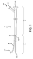
- Figure 1 Shown in Figure 1 is a catheter according to the present invention.
- Figure 1 shows a catheter 1 having a proximal portion 2, a distal portion 3, and a guidewire channel 4.
- the guidewire channel has a distal end 6 and a proximal end 5.
- the proximal end 5 is attached to the distal end 3 of the catheter at 15.
- Catheter 1 can include an optional guidewire lumen extending from the distal tip 10 to the proximal end 12 of the catheter assembly.
- the catheter assembly can further include proximal hub assembly 13.
- the catheter may further include an expandable prosthesis loaded on the distal portion thereof.
- the expandable prosthesis comprises a first open end and a second open end, a wall extending from the first open end to the second open end, and at least one side opening in the wall.
- the expandable prosthesis can be either self-expanding or balloon expandable.
- a self-expanding prosthesis will comprise at least one shape memory material, such as nitinol.
- the expandable prosthesis can comprise a stent or stent graft.
- Suitable stent materials include, in addition to nitinol, for example, metallic, polymeric or natural materials and can comprise conventional medical grade materials such as nylon, polyacrylamide, polycarbonate, polyethylene, polyformaldehyde, polymethylmethacrylate, polypropylene, polytetrafluoroethylene, polytrifluorochlorethylene, polyvinylchloride, polyurethane, elastomeric organosilicon polymers; metals such as stainless steels, cobalt-chromium alloys and nitinol and biologically derived materials such as bovine arteries/veins, pericardium and collagen.
- conventional medical grade materials such as nylon, polyacrylamide, polycarbonate, polyethylene, polyformaldehyde, polymethylmethacrylate, polypropylene, polytetrafluoroethylene, polytrifluorochlorethylene, polyvinylchloride, polyurethane, elastomeric organosilicon polymers
- metals such as stainless steels, cobal
- Stents can also comprise bioresorbable materials such as poly(amino acids), poly(anhydrides), poly(caprolactones), poly(lactic/glycolic acid) polymers, poly(hydroxybutyrates) and poly(orthoesters).
- bioresorbable materials such as poly(amino acids), poly(anhydrides), poly(caprolactones), poly(lactic/glycolic acid) polymers, poly(hydroxybutyrates) and poly(orthoesters).
- the expandable prosthesis can comprise a stent at either the first open end, the second open end, or at both the first open end and the second open end.
- the stent can be a single stent extending from the first open end to the second open end.
- graft material is used to form the wall and extends from the first open end to the second open end of the expandable prosthesis.
- Grafts can have various configurations and can be fabricated, for example, from tubes, sheets or films formed into tubular shapes, woven or knitted fibers or ribbons or combinations thereof. Graft materials can include conventional medical grade materials such as nylon, polyester, polyethylene, polypropylene, polytetrafluoroethylene, polyurethane and elastomeric organosilicon polymers.
- Stents can be used alone or in combination with graft materials. Stents can be configured on the external or internal surface of a graft or may be incorporated into the internal wall structure of a graft.
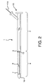
- Figure 2 is a side view of a catheter assembly 1 having a proximal catheter portion 2 and a proximal hub assembly 13. Loaded on the distal catheter portion is an expandable stent (or stent graft) 8. The expandable stent 8 is shown in a compressed state, maintained by a constraining sleeve 7. Also shown is distal end 6 of the guidewire channel extending out of a side opening in the stent 8, and proximal end 5 of the guidewire channel extending from the proximal end of stent 8 and being attached to the distal end of the catheter at 15.
- Figure 3 is a flow chart depicting the assembly and delivery sequence of a catheter having a guidewire channel according to an aspect of the invention. Following are details relating to the steps listed on flowchart Figure 3 :
- Step 1) PLACE EXPANDED MAIN-BODY DEVICE ONTO FIRST TEMPORARY TUBE.
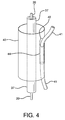
- FIG. 4 Shown in Figure 4 is an expanded main body stent graft 40 having a side wall opening 42 and an internal side branch support 44.
- a first temporary tube 37 can be inserted through the stent graft main body lumen.
- a first stiffening mandrel 39 can be positioned within the first temporary tube.
- the stent graft can be fabricated according to the methods and materials as generally disclosed in US Patent Nos. 6,042,605 , 6,361,637 , and 6,520,986, all to Martin et al . Details relating to the fabrication and materials used for an internal side branch support tube can be found in US Patent No. 6,645,242, to Quinn .
- Step 2) PLACE SECOND TEMPORARY TUBE THROUGH SIDE BRANCH SUPPORT.
- a second temporary tube 41 can be routed through the side wall opening 42 and through the internal side branch support 44.
- Step 3 COMPRESS MAIN BODY, ADD CONSTRAINING SHEATH
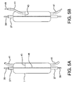
- the main body stent (40, Fig. 4 ) can be compressed and held in the compressed state by a constraining sheath 7.
- the sheath can be laced together by a deployment cord 46.
- the sheath lacing forms a generally longitudinal seam along the constraining sheath.
- the constraining sheath can be provided with a slit 43 that is oriented perpendicular to the longitudinal seam formed by deployment cord 46. The slit will subsequently provide an exit point for the second temporary tube 41. Details relating to constraining sheath materials, sheath methods of manufacture and main body compression techniques can be found, for example, in US Patent No. 6,352,561 to Leopold et al. , and US Patent No. 6,551,350 Thornton et al .
- Step 4) ROUTE DISTAL END OF SECOND TEMPORARY TUBE THROUGH SLIT IN CONSTRAINING SHEATH.
- the second temporary tube 41 can be routed through the slit 43.
- a small spring puller or hook can be inserted through the slit and be used to engage the lumen of the second temporary tube. Once the lumen is engaged the second tube can be pulled through the slit as shown in Figure 5B .
- a second stiffening mandrel 49 can be inserted through the second temporary tube.
- Step 5 REMOVE FIRST AND SECOND TEMPORARY TUBES, LEAVING BOTH STIFFENING MANDRELS IN PLACE.
- the two temporary tubes 37 and 41 can be removed, leaving the two stiffening mandrels 39 and 49 in place.
- Step 6 PUSH MAIN BODY GUIDEWIRE LUMEN AND ATTACHED GUIDEWIRE CHANNEL OVER MANDRELS.
- a catheter 1 can be provided having a proximal portion 2 and a distal portion 3.
- a hub assembly 13 can be attached to the proximal catheter portion 2.
- the hub assembly 13 has a main guidewire lumen extending from the proximal end 12, through the hub assembly, to the distal end 10 of the catheter 1.
- a deployment cord lumen 14 Also shown is a deployment cord lumen 14.
- the distal catheter portion 3 is shown having a guidewire channel 4 that is attached to the catheter at the juncture 15.
- the distal portion of the guidewire lumen can be placed onto the first stiffening mandrel 39 while the attached guidewire channel 4 is simultaneously placed onto the second stiffening mandrel 49.
- the catheter assembly can then be fully advanced so that the guidewire lumen and the attached guidewire channel 4 are driven through the compressed device.
- Step 7) BOND DISTAL TIP ONTO DISTAL CATHETER PORTION AND REMOVE MANDRELS.
- a compliant tip 16 can then be molded onto the distal end of catheter 1, as shown in Figure 2 .
- the distal end 6 of the guidewire channel 4 can then be trimmed to length.
- the catheter and hub can comprise conventional medical grade materials such as nylon, polyacrylamide, polycarbonate, polyethylene, polyformaldehyde, polymethylmethacrylate, polypropylene, polytetrafluoroethylene, polytrifluorochlorethylene, polyvinylchloride, polyurethane, elastomeric organosilicon polymers, Pebax® polyether block amide, and metals such as stainless steels and nitinol.
- conventional medical grade materials such as nylon, polyacrylamide, polycarbonate, polyethylene, polyformaldehyde, polymethylmethacrylate, polypropylene, polytetrafluoroethylene, polytrifluorochlorethylene, polyvinylchloride, polyurethane, elastomeric organosilicon polymers, Pebax® polyether block amide, and metals such as stainless steels and nitinol.
- the proximal and distal catheter portions can have diameters and lengths suitable for the delivery of a variety of stent configurations.
- Catheter diameters can range from about 1 mm to over 20 mm, with a preferred range of about 2 mm to about 15 mm, with a most preferred range of about 2 mm to about 6 mm.
- Catheter lengths can vary from about 20 cm to over 100 cm.
- Lengths of distal catheter portions can vary from about 5 cm to over 20 cm.
- Materials useful as catheter and hub materials are also useful for fabricating the guidewire channel.
- the device can then be delivered and implanted according to the following procedure.
- two guidewires can be placed into native vessels. Shown are a main body guidewire 50 placed into a main vessel 52 and a side branch guidewire 54 placed into a side branch vessel 56.
- An introducer sheath (not shown) can be used during the guidewire placement.
- a hemostatic valve (not shown) is typically used to control back-bleeding during the guidewire and subsequent device placement.
- Typical guidewires (with 0.035" and 0.014" diameters) can be used.
- Step 9) BACKLOAD GUIDEWIRE CHANNEL and MAIN BODY DEVICE ONTO TWO GUIDEWIRES.
- the catheter assembly 1 can be back loaded onto the two guidewires.
- the main body guidewire 50 is threaded into the catheter main guidewire lumen at distal tip 36, while the side branch guidewire 54 is threaded into the guidewire channel 4.
- the guidewires are fully inserted through the catheter main body lumen and through the guidewire channel, as depicted in Figure 7 . Shown is a main body guidewire 50 fully inserted through the catheter main guidewire lumen and a side branch guidewire 54 fully inserted through the guidewire channel 4.
- Step 10 ADVANCE COMPRESSED DEVICE TO TARGET SITE
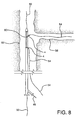
- the catheter assembly can now be advanced to the target site. As shown in Figure 8 the catheter and compressed main body device are advanced along the two guidewires 50, 54 until the sheath aperture 60 is aligned to the side branch vessel 56.
- the deployment cord 46 is pulled in the direction shown by arrow 62.
- the constraining sheath is split allowing the main body device 40 to self-expand and engage the main vessel 52.
- Guidewire 54 will be released from guidewire channel 4 upon expansion of device 40.
- the constraining sheath (not shown) can be left in-vivo since the sheath will be captured between the main body stent and the main vessel lumen.
- the side branch guidewire remains routed through the main body side wall opening 42, through the internal side branch support 44 and out through the proximal end of the main body device.
- the catheter 1 can now be removed, leaving the expanded main body device 40 and the side branch guidewire 54 in place.
- Step 13 BACKLOAD SIDE BRANCH DEVICE ONTO SIDE BRANCH GUIDEWIRE.
- a compressed side branch stent graft can then be back loaded onto the side branch guidewire.
- the side branch guidewire 54 can be inserted into a side branch guidewire lumen at the distal tip 66 of device 64.
- the compressed side branch device 64 can then be advanced in the direction indicated by arrow 68.
- the compressed side branch device can be a stent or stent graft and can be constructed similar to the main body device 40, discussed above.
- Step 14 ADVANCE COMPRESSED SIDE BRANCH DEVICE THROUGH INTERNAL SIDE BRANCH SUPPORT CHANNEL
- the compressed side branch device 64 can be fully advanced along guidewire 54 so that the compressed device exits the main body side wall opening 42 and enters the side branch vessel 56.
- the side branch constraining sheath can be released by pulling on the deployment cord 70 along the direction indicated by arrow 72. As shown in Figure 12 , the release of the constraining sheath allows the side branch device 76 to self-expand and engage the side branch vessel 56, the main body side wall opening 42 and the internal side-branch support channel 44.
- the side branch catheter can be removed after the side branch device is fully expanded.
- the constraining sheath (not shown) can be left in-vivo since the sheath will be captured in a fashion similar to that of the previous main body device.
- the catheter of the invention can be used to deliver an expandable stent graft and expandable side branch device to, for example, the aortic arch branches (arteries of the head, arms, and hands), lower branches of the aorta (celiac), renals, mesenterics, iliacs, the femoral, and lower extremities (legs, feet).
- aortic arch branches arteries of the head, arms, and hands
- lower branches of the aorta celiac
- renals mesenterics
- iliacs iliacs
- femoral femoral
- lower extremities legs, feet
- a catheter having an attached guidewire channel can be fabricated as follows:
- the present invention further comprises the following numbered embodiments.
- a catheter comprising: catheter body having a proximal portion, a distal portion, a proximal end, and a distal end; and at least one guidewire channel having a proximal end, a distal end, and a longitudinally extending opening therein extending from the channel proximal end to the channel distal end, the channel proximal end being attached to the catheter body at the distal portion thereof and extending in a distal direction therefrom.
- the catheter of the first embodiment wherein an expandable prosthesis is loaded on the distal portion of the catheter and the channel proximal end extends proximally from the expandable prosthesis and the channel distal end extends out of a side opening in the expandable prosthesis.
- the catheter of the second embodiment wherein the expandable prosthesis comprises a stent.
- the catheter of the third embodiment wherein the stent comprises a shape- memory material.
- the catheter of the second embodiment wherein the expandable prosthesis is balloon expandable.
- the catheter of the second embodiment wherein the expandable prosthesis comprises a stent graft.
- the catheter of the sixth embodiment wherein the graft comprises a material selected from the group consisting of ePTFE, nylon, polyester, polyethylene, polypropylene, polytetrafluoroethylene, polyurethane, and elastomeric organosilicon polymers.
- the catheter of the sixth embodiment wherein the stent graft comprises a first stent at a first open end and a second stent at a second open end of the stent graft.
- a ninth embodiment there is provided the catheter of the eighth embodiment, wherein the graft material extends from the first open end to the second open end.
- the catheter of the first embodiment wherein the catheter further comprises a guidewire lumen extending from the catheter distal end to a point proximal thereto.
- the catheter of the first embodiment wherein the guidewire channel comprises a material selected from the group consisting of nylon, polyether block amide, polyurethane, and polyethylene.
- the catheter of the first embodiment further comprising a guidewire configured to be inserted into the guidewire channel.
- the catheter of the sixth embodiment wherein the stent graft comprises a first open end, a second open end, a side opening, and an internal side branch support.
- the catheter of the thirteenth embodiment wherein the internal side branch support extends from the stent graft side opening toward the second open end.
- the catheter of the second embodiment wherein the expandable prosthesis further comprises a sheath material wrapped over the expandable prosthesis.
- the catheter of the fifteenth embodiment wherein the sheath material has at least one opening therein.
- the catheter of the sixteenth embodiment wherein the guidewire channel extends through the at least one opening in the sheath material.
- a method for delivering an expandable prosthetic device comprising the steps of: advancing a main body guidewire into a main vessel; advancing a side branch guidewire into a side branch vessel; providing a first catheter body having a proximal portion, a distal portion, a proximal end, a distal end, a lumen extending from the distal end to a point proximal thereto, at least one guidewire channel having a proximal end, a distal end, and a longitudinally extending opening therein extending from the channel proximal end to the channel distal end, the channel proximal end being attached to the catheter body at the distal portion thereof and extending in a distal direction therefrom; expandable main body device loaded on the distal portion of the first catheter, the expandable main body device having a first open end, a second open end, a wall extending from the first open end to the second open end, a lumen extending from the first open
- the method of the eighteenth embodiment further comprising the steps of: providing a second catheter having a distal end, a proximal end, a distal portion, a proximal portion, a lumen extending from the distal end to the proximal end, and an expandable side branch device loaded on the distal portion; advancing the second catheter and the expandable side branch device through the expanded main body device, out the side opening, and at least partially into the side branch vessel; expanding the side branch device; and removing the second catheter.
Abstract
Description
- The present invention relates to catheters useful for delivering expandable endoluminal prostheses. The catheters are particularly suited for use in delivering expandable endoluminal prostheses to bifurcated regions of body lumens.
- Stents or stent grafts are examples of expandable endoluminal prosthetic devices which are used to maintain, open or dilate stenotic lesions in body lumens or to cover and repair an aneurysm. Vascular disease may occur at a branch or bifurcation in a vessel. Placement and deployment of these prosthetic devices at bifurcations can often be problematic. One current technique is to initially deploy across an aneurysm a main body prosthetic device having a side wall opening. The side wall opening is aligned with the side branch ostium. A second prosthetic device is then deployed through the main body prosthetic device side wall opening and into the side branch vessel. Procedural complications are often encountered while practicing this technique. These complications typically relate to the accurate placement of the main body prosthetic device and in particular to the precise alignment of the side wall opening to the native side branch vessel. Subsequent placement of the side branch guidewire through the main body prosthetic device, through the side wall opening and then into the side branch vessel can also be problematic. The deployment of the side branch prosthetic device into the native vessel can present problems relating to the longitudinal placement of the device.
- Alternate procedures for treating bifurcated vessels place the guidewires prior to the device deployments. After the main body prosthetic device is deployed it is advantageous to then remove the main body delivery catheter prior to the delivery of the side branch prosthetic device. Typical delivery systems incorporate guidewires that are contained or captured within the delivery catheter. The catheter removal therefore requires careful management of the side branch guidewire to prevent its dislodgement during the removal of the delivery catheter.
- An aspect of the invention includes a catheter comprising:
- Catheter body having a proximal portion, a distal portion, a proximal end, and a distal end; and
- At least one guidewire channel having a proximal end and a distal end, the at least one guidewire channel having a longitudinal opening therein extending from the channel proximal end to the channel distal end, the proximal end of the at least one guidewire channel being attached to the catheter body at the distal portion of the catheter body.
- The catheter body can include a guidewire lumen extending from the catheter body distal end to a point proximal thereto.
- Further, an expandable prosthesis can be loaded on the distal end of the catheter, with the guidewire channel proximal end extending proximally from the expandable prosthesis and the guidewire channel distal end extending out of a side opening in the expandable prosthesis.
- A further aspect of the invention provides methods for delivering an expandable prosthesis using the catheter of the invention that overcome the drawbacks relating to conventional devices and delivery methods.
-
-
Figure 1 is a side view of a catheter according to an aspect of the invention. -
Figure 2 is a side view of a catheter assembly having an expandable prosthetic device loaded on the distal portion thereof. -
Figure 3 is a flow chart listing the process steps used for the fabrication and delivery of a catheter assembly according to an aspect of the invention. -
Figure 4 is a perspective view of an expanded main body stent graft with first temporary tube routed through the main body lumen and a second temporary tube routed through a side branch support. -
Figures 5A and 5B are perspective views of a compressed and constrained main body stent graft displaying the routing of two temporary tubes. -
Figure 6 is a schematic diagram showing pre-placed guidewires loaded through a compressed device with a removable guidewire tube. -
Figure 7 is a schematic diagram showing a main guidewire routed through a catheter main lumen and a side branch guidewire routed through a guidewire channel. -
Figure 8 is a schematic diagram showing a compressed main body stent graft positioned at a branch vessel target site. -
Figure 9 is schematic diagram showing an expanded main body stent graft having a side branch opening aligned to a side branch vessel. -
Figure 10 illustrates the initial advancement of a compressed side branch device. -
Figure 11 illustrates a compressed side branch device routed through the main body stent graft and into the side branch vessel. -
Figure 12 illustrates a fully deployed main body stent graft and a fully deployed side branch device. - An aspect of the invention includes a catheter comprising:
- Catheter body having a proximal portion, a distal portion, a proximal end, and a distal end; and
- At least one guidewire channel having a proximal end and a distal end, the at least one guidewire channel having a longitudinal opening therein extending from the channel proximal end to the channel distal end, the proximal end of the at least one guidewire channel being attached to the catheter body at the distal portion of the catheter body.
- The catheter body can include a guidewire lumen extending from the catheter body distal end to a point proximal thereto.
- Further, an expandable prosthesis can be loaded on the distal end of the catheter, with the guidewire channel proximal end extending proximally from the expandable prosthesis and the guidewire channel distal end extending out of a side opening in the expandable prosthesis.
- A further aspect of the invention provides methods for delivery of an expandable prosthesis that overcome the drawbacks relating to conventional devices and delivery methods. The present invention allows for the initial placement of multiple guidewires into selected target sites. The guidewire placement is simplified since there are no endoluminal devices complicating the guidewire placement. As a failsafe, the procedure can be aborted if the guidewires cannot be properly placed. After proper placement of the guidewires is confirmed, a main body, expandable prosthetic device can be advanced to the treatment site. This main body device has a separate side branch guidewire that passes through the main body device and through the side opening in the main body device. Therefore as the main body device is advanced, the side opening is self guided (by the side branch guidewire) and self aligns to the side branch vessel ostium. The main body device is then deployed, leaving the side branch guidewire in place. The side branch guidewire is released from the catheter as the main body device is deployed. The delivery catheter can then be readily removed without dislodging the placement of the side branch guidewire. A side branch prosthetic device can then be advanced along the side branch guidewire through the main body device, through the side wall opening and into the native side branch vessel. The side branch device can then be deployed to engage the main body device and the native side branch vessel.
- Further understanding of the invention may be had with reference to the figures. Shown in
Figure 1 is a catheter according to the present invention. -
Figure 1 shows acatheter 1 having aproximal portion 2, adistal portion 3, and aguidewire channel 4. The guidewire channel has adistal end 6 and aproximal end 5. Theproximal end 5 is attached to thedistal end 3 of the catheter at 15.Catheter 1 can include an optional guidewire lumen extending from thedistal tip 10 to theproximal end 12 of the catheter assembly. The catheter assembly can further includeproximal hub assembly 13. - The catheter may further include an expandable prosthesis loaded on the distal portion thereof.
- The expandable prosthesis comprises a first open end and a second open end, a wall extending from the first open end to the second open end, and at least one side opening in the wall.
- The expandable prosthesis can be either self-expanding or balloon expandable. Typically, a self-expanding prosthesis will comprise at least one shape memory material, such as nitinol. The expandable prosthesis can comprise a stent or stent graft. Suitable stent materials include, in addition to nitinol, for example, metallic, polymeric or natural materials and can comprise conventional medical grade materials such as nylon, polyacrylamide, polycarbonate, polyethylene, polyformaldehyde, polymethylmethacrylate, polypropylene, polytetrafluoroethylene, polytrifluorochlorethylene, polyvinylchloride, polyurethane, elastomeric organosilicon polymers; metals such as stainless steels, cobalt-chromium alloys and nitinol and biologically derived materials such as bovine arteries/veins, pericardium and collagen. Stents can also comprise bioresorbable materials such as poly(amino acids), poly(anhydrides), poly(caprolactones), poly(lactic/glycolic acid) polymers, poly(hydroxybutyrates) and poly(orthoesters).
- The expandable prosthesis can comprise a stent at either the first open end, the second open end, or at both the first open end and the second open end. Moreover, the stent can be a single stent extending from the first open end to the second open end. In an aspect of the invention, graft material is used to form the wall and extends from the first open end to the second open end of the expandable prosthesis. Grafts can have various configurations and can be fabricated, for example, from tubes, sheets or films formed into tubular shapes, woven or knitted fibers or ribbons or combinations thereof. Graft materials can include conventional medical grade materials such as nylon, polyester, polyethylene, polypropylene, polytetrafluoroethylene, polyurethane and elastomeric organosilicon polymers.
- Stents can be used alone or in combination with graft materials. Stents can be configured on the external or internal surface of a graft or may be incorporated into the internal wall structure of a graft.
-
Figure 2 is a side view of acatheter assembly 1 having aproximal catheter portion 2 and aproximal hub assembly 13. Loaded on the distal catheter portion is an expandable stent (or stent graft) 8. Theexpandable stent 8 is shown in a compressed state, maintained by a constrainingsleeve 7. Also shown isdistal end 6 of the guidewire channel extending out of a side opening in thestent 8, andproximal end 5 of the guidewire channel extending from the proximal end ofstent 8 and being attached to the distal end of the catheter at 15. -
Figure 3 is a flow chart depicting the assembly and delivery sequence of a catheter having a guidewire channel according to an aspect of the invention. Following are details relating to the steps listed on flowchartFigure 3 : - Shown in
Figure 4 is an expanded mainbody stent graft 40 having a side wall opening 42 and an internalside branch support 44. A firsttemporary tube 37 can be inserted through the stent graft main body lumen. Afirst stiffening mandrel 39 can be positioned within the first temporary tube. The stent graft can be fabricated according to the methods and materials as generally disclosed inUS Patent Nos. 6,042,605 ,6,361,637 , and6,520,986, all to Martin et al . Details relating to the fabrication and materials used for an internal side branch support tube can be found inUS Patent No. 6,645,242, to Quinn . - Referring to
Figure 4 , a secondtemporary tube 41 can be routed through the side wall opening 42 and through the internalside branch support 44. - Referring to
Figure 5A , the main body stent (40,Fig. 4 ) can be compressed and held in the compressed state by a constrainingsheath 7. The sheath can be laced together by adeployment cord 46. The sheath lacing forms a generally longitudinal seam along the constraining sheath. The constraining sheath can be provided with aslit 43 that is oriented perpendicular to the longitudinal seam formed bydeployment cord 46. The slit will subsequently provide an exit point for the secondtemporary tube 41. Details relating to constraining sheath materials, sheath methods of manufacture and main body compression techniques can be found, for example, inUS Patent No. 6,352,561 to Leopold et al. , andUS Patent No. 6,551,350 Thornton et al . - As shown in
Figure 5B , the secondtemporary tube 41 can be routed through theslit 43. A small spring puller or hook can be inserted through the slit and be used to engage the lumen of the second temporary tube. Once the lumen is engaged the second tube can be pulled through the slit as shown inFigure 5B . After the secondtemporary tube 41 is routed through the constraining sheath, asecond stiffening mandrel 49 can be inserted through the second temporary tube. - The two
temporary tubes stiffening mandrels - Referring to
Figure 1 , acatheter 1 can be provided having aproximal portion 2 and adistal portion 3. Ahub assembly 13 can be attached to theproximal catheter portion 2. Thehub assembly 13 has a main guidewire lumen extending from theproximal end 12, through the hub assembly, to thedistal end 10 of thecatheter 1. Also shown is adeployment cord lumen 14. Thedistal catheter portion 3 is shown having aguidewire channel 4 that is attached to the catheter at thejuncture 15. The distal portion of the guidewire lumen can be placed onto thefirst stiffening mandrel 39 while the attachedguidewire channel 4 is simultaneously placed onto thesecond stiffening mandrel 49. The catheter assembly can then be fully advanced so that the guidewire lumen and the attachedguidewire channel 4 are driven through the compressed device. - A
compliant tip 16 can then be molded onto the distal end ofcatheter 1, as shown inFigure 2 . Thedistal end 6 of theguidewire channel 4 can then be trimmed to length. - The catheter and hub can comprise conventional medical grade materials such as nylon, polyacrylamide, polycarbonate, polyethylene, polyformaldehyde, polymethylmethacrylate, polypropylene, polytetrafluoroethylene, polytrifluorochlorethylene, polyvinylchloride, polyurethane, elastomeric organosilicon polymers, Pebax® polyether block amide, and metals such as stainless steels and nitinol.
- The proximal and distal catheter portions can have diameters and lengths suitable for the delivery of a variety of stent configurations. Catheter diameters can range from about 1 mm to over 20 mm, with a preferred range of about 2 mm to about 15 mm, with a most preferred range of about 2 mm to about 6 mm. Catheter lengths can vary from about 20 cm to over 100 cm. Lengths of distal catheter portions can vary from about 5 cm to over 20 cm.
- Materials useful as catheter and hub materials are also useful for fabricating the guidewire channel.
- The device can then be delivered and implanted according to the following procedure.
- As shown in
Figure 6 , two guidewires can be placed into native vessels. Shown are a main body guidewire 50 placed into amain vessel 52 and a side branch guidewire 54 placed into aside branch vessel 56. An introducer sheath (not shown) can be used during the guidewire placement. A hemostatic valve (not shown) is typically used to control back-bleeding during the guidewire and subsequent device placement. Typical guidewires (with 0.035" and 0.014" diameters) can be used. - As further shown in
Figure 7 , thecatheter assembly 1 can be back loaded onto the two guidewires. The main body guidewire 50 is threaded into the catheter main guidewire lumen atdistal tip 36, while the side branch guidewire 54 is threaded into theguidewire channel 4. - The guidewires are fully inserted through the catheter main body lumen and through the guidewire channel, as depicted in
Figure 7 . Shown is a main body guidewire 50 fully inserted through the catheter main guidewire lumen and a side branch guidewire 54 fully inserted through theguidewire channel 4. - The catheter assembly can now be advanced to the target site. As shown in
Figure 8 the catheter and compressed main body device are advanced along the twoguidewires sheath aperture 60 is aligned to theside branch vessel 56. - As shown in
Figure 9 , thedeployment cord 46 is pulled in the direction shown byarrow 62. By pulling on thedeployment cord 46 the constraining sheath is split allowing themain body device 40 to self-expand and engage themain vessel 52.Guidewire 54 will be released fromguidewire channel 4 upon expansion ofdevice 40. The constraining sheath (not shown) can be left in-vivo since the sheath will be captured between the main body stent and the main vessel lumen. The side branch guidewire remains routed through the main body side wall opening 42, through the internalside branch support 44 and out through the proximal end of the main body device. - The
catheter 1 can now be removed, leaving the expandedmain body device 40 and the side branch guidewire 54 in place. - A compressed side branch stent graft can then be back loaded onto the side branch guidewire. As shown in
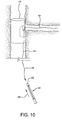
Figure 10 , the side branch guidewire 54 can be inserted into a side branch guidewire lumen at thedistal tip 66 ofdevice 64. The compressedside branch device 64 can then be advanced in the direction indicated byarrow 68. The compressed side branch device can be a stent or stent graft and can be constructed similar to themain body device 40, discussed above. - As shown in
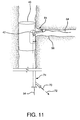
Figure 11 , the compressedside branch device 64 can be fully advanced alongguidewire 54 so that the compressed device exits the main body side wall opening 42 and enters theside branch vessel 56. - Referring to
Figure 11 , the side branch constraining sheath can be released by pulling on thedeployment cord 70 along the direction indicated byarrow 72. As shown inFigure 12 , the release of the constraining sheath allows theside branch device 76 to self-expand and engage theside branch vessel 56, the main body side wall opening 42 and the internal side-branch support channel 44. The side branch catheter can be removed after the side branch device is fully expanded. The constraining sheath (not shown) can be left in-vivo since the sheath will be captured in a fashion similar to that of the previous main body device. - The catheter of the invention can be used to deliver an expandable stent graft and expandable side branch device to, for example, the aortic arch branches (arteries of the head, arms, and hands), lower branches of the aorta (celiac), renals, mesenterics, iliacs, the femoral, and lower extremities (legs, feet).
- A catheter having an attached guidewire channel can be fabricated as follows:
- 1) A self-expanding, main body stent graft can be provided having an outer diameter of 3.1 cm, a length of 15 cm and a graft wall thickness of about 0.005". The graft material can be comprised of ePTFE and FEP and formed from an extruded and expanded thin walled tube that can be subsequently wrapped with ePTFE film. A nitinol wire having a diameter of about 0.0165" can be helically wound to form a stent having an undulating, sinusoidal pattern. The formed, heat-treated stent can be placed onto the base graft. An additional film layer of ePTFE and FEP can be wrapped onto the stent and base graft to selectively adhere the stent to the graft.
- 2) The main body stent graft can have an internal side-branch support channel formed into the graft wall. Details relating to exemplary fabrication and materials used for an internal side branch support channel can be found in
US Patent No. 6,645,242 to Quinn . - 3) A first temporary polymeric tube (PTFE, 0.066" OD) can be placed through the main body stent.
- 4) A second temporary polymeric tube (PTFE) can be threaded through the main body stent, through the internal side branch support and out through the main body side wall opening.
- 5) The stent device can be compressed using temporary tethers and a tapered pull-through compression die. The main body stent can be compressed and maintained in the compressed state by a removable constraining sheath.
- 6) Two wires having 0.038" diameters can be threaded through the first and second polymeric tubes. The polymeric tubes can be removed, leaving the two wires in place, the first through the main body stent and the second through the side branch support.
- 7) A distal catheter portion with an attached guidewire channel can be provided. The guidewire channel can be formed from a Pebax® 7233 tube having a 0.038" inner diameter and a 0.066" outer diameter. A 0.029" diameter metal wire can be inserted into a 20 cm length of the tube. Using a sharp razor, the tube wall can be skived longitudinally along the top of the internal wire. A channel, having an open width of about 0.036" can therefore be formed along the tube. This 0.036" opening can be sized to allow a 0.035" guidewire to be released from the channel during subsequent device deployment. The channel can be thermally bonded to the proximal end of the distal catheter portion.
The distal catheter portion should not have an enlarged tip so as to facilitate the loading of the compressed device. The compressed device can be transferred onto the distal catheter portion. The attached guidewire channel can be guided over the second wire and through the side branch support. The main catheter shaft can be simultaneously guided over the first wire and through the main body stent. An enlarged tip can be bonded to the distal end of the catheter. - 8) The catheter proximal portion and the hub assembly can be bonded together. The deployment cord can be appropriately routed through the proximal catheter and hub assembly. The guidewire channel can be trimmed flush to the constraining sheath.
- The present invention further comprises the following numbered embodiments.
- In a first embodiment, there is provided a catheter comprising: catheter body having a proximal portion, a distal portion, a proximal end, and a distal end; and at least one guidewire channel having a proximal end, a distal end, and a longitudinally extending opening therein extending from the channel proximal end to the channel distal end, the channel proximal end being attached to the catheter body at the distal portion thereof and extending in a distal direction therefrom.
- In a second embodiment, there is provided the catheter of the first embodiment, wherein an expandable prosthesis is loaded on the distal portion of the catheter and the channel proximal end extends proximally from the expandable prosthesis and the channel distal end extends out of a side opening in the expandable prosthesis.
- In a third embodiment, there is provided the catheter of the second embodiment, wherein the expandable prosthesis comprises a stent.
- In a fourth embodiment, there is provided the catheter of the third embodiment, wherein the stent comprises a shape- memory material.
- In a fifth embodiment, there is provided the catheter of the second embodiment, wherein the expandable prosthesis is balloon expandable.
- In a sixth embodiment, there is provided the catheter of the second embodiment, wherein the expandable prosthesis comprises a stent graft.
- In a seventh embodiment, there is provided the catheter of the sixth embodiment, wherein the graft comprises a material selected from the group consisting of ePTFE, nylon, polyester, polyethylene, polypropylene, polytetrafluoroethylene, polyurethane, and elastomeric organosilicon polymers.
- In an eighth embodiment, there is provided the catheter of the sixth embodiment, wherein the stent graft comprises a first stent at a first open end and a second stent at a second open end of the stent graft.
- In a ninth embodiment, there is provided the catheter of the eighth embodiment, wherein the graft material extends from the first open end to the second open end.
- In a tenth embodiment, there is provided the catheter of the first embodiment, wherein the catheter further comprises a guidewire lumen extending from the catheter distal end to a point proximal thereto.
- In an eleventh embodiment, there is provided the catheter of the first embodiment, wherein the guidewire channel comprises a material selected from the group consisting of nylon, polyether block amide, polyurethane, and polyethylene.
- In a twelfth embodiment, there is provided the catheter of the first embodiment, further comprising a guidewire configured to be inserted into the guidewire channel.
- In a thirteenth embodiment, there is provided the catheter of the sixth embodiment, wherein the stent graft comprises a first open end, a second open end, a side opening, and an internal side branch support.
- In a fourteenth embodiment, there is provided the catheter of the thirteenth embodiment, wherein the internal side branch support extends from the stent graft side opening toward the second open end.
- In a fifteenth embodiment, there is provided the catheter of the second embodiment, wherein the expandable prosthesis further comprises a sheath material wrapped over the expandable prosthesis.
- In a sixteenth embodiment, there is provided the catheter of the fifteenth embodiment, wherein the sheath material has at least one opening therein.
- In a seventeenth embodiment, there is provided the catheter of the sixteenth embodiment, wherein the guidewire channel extends through the at least one opening in the sheath material.
- In an eighteenth embodiment, there is provided a method for delivering an expandable prosthetic device comprising the steps of: advancing a main body guidewire into a main vessel; advancing a side branch guidewire into a side branch vessel; providing a first catheter body having a proximal portion, a distal portion, a proximal end, a distal end, a lumen extending from the distal end to a point proximal thereto, at least one guidewire channel having a proximal end, a distal end, and a longitudinally extending opening therein extending from the channel proximal end to the channel distal end, the channel proximal end being attached to the catheter body at the distal portion thereof and extending in a distal direction therefrom; expandable main body device loaded on the distal portion of the first catheter, the expandable main body device having a first open end, a second open end, a wall extending from the first open end to the second open end, a lumen extending from the first open end to the second open end, at least one side opening in the wall, wherein the guidewire channel extends from at least the main body device side opening, through the main body device lumen to a point proximal to the second open end; backloading the lumen of the first catheter and the lumen of the expandable main body device onto the main body guidewire; backloading the guidewire channel onto the side branch guidewire; advancing the first catheter and the main body device into the main vessel and aligning the side opening with the side branch vessel; expanding the main body device; and removing the first catheter.
- In a nineteenth embodiment, there is provided the method of the eighteenth embodiment, further comprising the steps of: providing a second catheter having a distal end, a proximal end, a distal portion, a proximal portion, a lumen extending from the distal end to the proximal end, and an expandable side branch device loaded on the distal portion; advancing the second catheter and the expandable side branch device through the expanded main body device, out the side opening, and at least partially into the side branch vessel; expanding the side branch device; and removing the second catheter.
Claims (15)
- Catheter (1) comprising:catheter body having a proximal portion (2), a distal portion (3), a proximal end (12), and a distal end (10);a guidewire lumen extending from the proximal end (12) to the distal end (10) of the catheter body;at least one guidewire channel (4) having a proximal end (5), a distal end (6), and a longitudinally extending opening therein extending from the channel proximal end to the channel distal end, the channel proximal end (5) being attached to the catheter body at the distal portion (3) thereof and extending in a distal direction therefrom, said at least one guidewire channel (4) having a u-shaped cross section; anda main body self-expandable prosthesis (40) loaded on the distal portion (3) of the catheter (1) and the channel proximal end (5) extends proximally from the expandable prosthesis (40) and the channel distal end (6) extends out a side opening (42) in the main body of the self-expandable prosthesis (40).
- Catheter (1) comprising:catheter body having a proximal portion (2), a distal portion (3), a proximal end (12), and a distal end (10);a guidewire lumen extending from the proximal end (12) to the distal end (10) of the catheter body;at least one guidewire channel (4) having a proximal end (5), a distal end (6), and a longitudinally extending opening therein extending from the channel proximal end to the channel distal end, the channel proximal end (5) being attached to the catheter body at the distal portion (3) thereof and extending in a distal direction therefrom, said at least one guidewire channel (4) obtainable by inserting a wire into a tube and skiving the tube wall along the top of the wire to thereby form a channel having an open width along the tube; anda main body self-expandable prosthesis (40) loaded on the distal portion (3) of the catheter (1) and the channel proximal end (5) extends proximally from the expandable prosthesis (40) and the channel distal end (6) extends out a side opening (42) in the main body of the self-expandable prosthesis (40).
- The catheter (1) of claim 1 or claim 2, wherein the expandable prosthesis (40) comprises a stent (8).
- The catheter (1) of claim 3, wherein the stent (8) comprises a shape- memory material.
- The catheter (1) of claim 1 or claim 2, wherein the expandable prosthesis (40) is balloon expandable.
- The catheter (1) of claim 1 or claim 2, wherein the expandable prosthesis (40) comprises a stent graft.
- The catheter (1) of claim 6, wherein the graft comprises a material selected from the group consisting of ePTFE, nylon, polyester, polyethylene, polypropylene, polytetrafluoroethylene, polyurethane, and elastomeric organosilicon polymers.
- The catheter (1) of claim 6, wherein the stent graft comprises a first stent at a first open end and a second stent at a second open end of the stent graft.
- The catheter (1) of claim 1 or claim 2, wherein the guidewire channel (4) comprises a material selected from the group consisting of nylon, polyether block amide, polyurethane, and polyethylene.
- The catheter (1) of claim 6, wherein the stent graft comprises a first open end, a second open end, a side opening, and an internal side branch support (44).
- The catheter (1) of claim 10, wherein the internal side branch support (44) extends from the stent graft side opening (42) toward the second open end.
- The catheter (1) of claim 1 or claim 2, wherein the expandable prosthesis (40) further comprises a sheath material (7) wrapped over the expandable prosthesis (40), optionally wherein the sheath material (7) has at least one opening (43) therein, and further optionally wherein the guidewire channel (4) extends through the at least one opening (43) in the sheath material (7).
- The catheter of claim 12, wherein sheath material includes opposite and spaced apart side edges,
wherein the catheter further comprises deployment line extending through the deployment line lumen and releasably coupling the side edges of the constraining sheath to form a longitudinal seam,
wherein the opening in the sheath material is in communication with the longitudinal seam. - The catheter of claim 13, wherein the opening in the constraining sheath extends through only one of the side edges.
- The catheter of claim 13 or claim 14, wherein the opening in the constraining sheath defines a length transverse to the longitudinal seam and a width perpendicular to the length of the opening in the constraining sheath, wherein the length of the opening in the constraining sheath is greater than the width of the opening in the constraining sheath.
Applications Claiming Priority (2)
| Application Number | Priority Date | Filing Date | Title |
|---|---|---|---|
| US11/739,169 US9358142B2 (en) | 2007-04-24 | 2007-04-24 | Catheter having guidewire channel |
| EP08779580.3A EP2139436B1 (en) | 2007-04-24 | 2008-04-08 | Method of assembling a catheter having guidewire channel |
Related Parent Applications (2)
| Application Number | Title | Priority Date | Filing Date |
|---|---|---|---|
| EP08779580.3A Division EP2139436B1 (en) | 2007-04-24 | 2008-04-08 | Method of assembling a catheter having guidewire channel |
| EP08779580.3A Division-Into EP2139436B1 (en) | 2007-04-24 | 2008-04-08 | Method of assembling a catheter having guidewire channel |
Publications (1)
| Publication Number | Publication Date |
|---|---|
| EP3037062A1 true EP3037062A1 (en) | 2016-06-29 |
Family
ID=39776355
Family Applications (2)
| Application Number | Title | Priority Date | Filing Date |
|---|---|---|---|
| EP08779580.3A Active EP2139436B1 (en) | 2007-04-24 | 2008-04-08 | Method of assembling a catheter having guidewire channel |
| EP16153699.0A Withdrawn EP3037062A1 (en) | 2007-04-24 | 2008-04-08 | Catheter having a guidewire channel |
Family Applications Before (1)
| Application Number | Title | Priority Date | Filing Date |
|---|---|---|---|
| EP08779580.3A Active EP2139436B1 (en) | 2007-04-24 | 2008-04-08 | Method of assembling a catheter having guidewire channel |
Country Status (7)
| Country | Link |
|---|---|
| US (1) | US9358142B2 (en) |
| EP (2) | EP2139436B1 (en) |
| JP (1) | JP5123376B2 (en) |
| AU (1) | AU2008241571B2 (en) |
| CA (1) | CA2683011C (en) |
| ES (1) | ES2581215T3 (en) |
| WO (1) | WO2008130503A2 (en) |
Families Citing this family (39)
| Publication number | Priority date | Publication date | Assignee | Title |
|---|---|---|---|---|
| WO2009105699A1 (en) | 2008-02-22 | 2009-08-27 | Endologix, Inc. | Design and method of placement of a graft or graft system |
| US8236040B2 (en) | 2008-04-11 | 2012-08-07 | Endologix, Inc. | Bifurcated graft deployment systems and methods |
| WO2010002931A1 (en) | 2008-07-01 | 2010-01-07 | Endologix, Inc. | Catheter system |
| WO2010036982A1 (en) | 2008-09-25 | 2010-04-01 | Henry Bourang | Partially crimped stent |
| US8828071B2 (en) | 2008-09-25 | 2014-09-09 | Advanced Bifurcation Systems, Inc. | Methods and systems for ostial stenting of a bifurcation |
| US11298252B2 (en) | 2008-09-25 | 2022-04-12 | Advanced Bifurcation Systems Inc. | Stent alignment during treatment of a bifurcation |
| US20110054587A1 (en) | 2009-04-28 | 2011-03-03 | Endologix, Inc. | Apparatus and method of placement of a graft or graft system |
| US20110087318A1 (en) | 2009-10-09 | 2011-04-14 | Daugherty John R | Bifurcated highly conformable medical device branch access |
| CA2794078A1 (en) | 2010-03-24 | 2011-09-29 | Advanced Bifurcation Systems, Inc. | Stent alignment during treatment of a bifurcation |
| CN103037815B (en) | 2010-03-24 | 2015-05-13 | 高级分支系统股份有限公司 | Methods and systems for treating a bifurcation with provisional side branch stenting |
| CN103037816B (en) | 2010-03-24 | 2018-12-28 | 高级分支系统股份有限公司 | System and method for handling furcation |
| WO2012061526A2 (en) | 2010-11-02 | 2012-05-10 | Endologix, Inc. | Apparatus and method of placement of a graft or graft system |
| EP2672932B1 (en) | 2011-02-08 | 2018-09-19 | Advanced Bifurcation Systems, Inc. | System for treating a bifurcation with a fully crimped stent |
| WO2012109382A2 (en) | 2011-02-08 | 2012-08-16 | Advanced Bifurcation Systems, Inc. | Multi-stent and multi-balloon apparatus for treating bifurcations and methods of use |
| EP2680915B1 (en) | 2011-03-01 | 2021-12-22 | Endologix LLC | Catheter system |
| US20120271410A1 (en) | 2011-04-19 | 2012-10-25 | Myles Douglas | Branch endograft delivery |
| US9314328B2 (en) | 2011-08-16 | 2016-04-19 | W. L. Gore & Associates, Inc. | Branched stent graft device and deployment |
| EP3272312B1 (en) | 2011-11-16 | 2019-05-22 | Bolton Medical, Inc. | Device for aortic branched vessel repair |
| US20140135786A1 (en) * | 2012-11-09 | 2014-05-15 | Naris Llc | Medical procedure access kit |
| US9662232B2 (en) | 2014-04-11 | 2017-05-30 | Red Vascular Technologies, LLC | Alignment system for multiple branch endografts |
| CN107624056B (en) | 2015-06-30 | 2020-06-09 | 恩朵罗杰克斯股份有限公司 | Locking assembly and related system and method |
| US10512533B1 (en) | 2016-02-23 | 2019-12-24 | W. L. Gore & Associates, Inc. | Branched graft assembly method in vivo |
| EP3903732A1 (en) | 2016-06-13 | 2021-11-03 | Aortica Corporation | Devices for reinforcing fenestrations in prosthetic implants |
| JP7181856B2 (en) | 2016-08-02 | 2022-12-01 | ボルトン メディカル インコーポレイテッド | Systems, instruments, and methods for bonding prosthetic implants to fenestrated bodies |
| AU2017307628C1 (en) | 2016-08-05 | 2020-09-03 | W. L. Gore & Associates, Inc. | Integrated medical device constraining lumen |
| ES2874197T3 (en) | 2016-09-15 | 2021-11-04 | Gore & Ass | Staged deployment of expandable implant |
| CN110022795B (en) | 2017-02-24 | 2023-03-14 | 波顿医疗公司 | Constrained stent grafts, delivery systems and methods of use |
| WO2018156849A1 (en) | 2017-02-24 | 2018-08-30 | Bolton Medical, Inc. | Vascular prosthesis with fenestration ring and methods of use |
| EP3534848B1 (en) * | 2017-02-24 | 2023-06-28 | Bolton Medical, Inc. | Stent graft delivery system with constricted sheath |
| EP3838220A1 (en) | 2017-02-24 | 2021-06-23 | Bolton Medical, Inc. | System to radially constrict a stent graft |
| WO2018156850A1 (en) | 2017-02-24 | 2018-08-30 | Bolton Medical, Inc. | Stent graft with fenestration lock |
| EP3534838B1 (en) | 2017-02-24 | 2021-01-27 | Bolton Medical, Inc. | Radially adjustable stent graft delivery system |
| WO2018156848A1 (en) | 2017-02-24 | 2018-08-30 | Bolton Medical, Inc. | Vascular prosthesis with crimped adapter and methods of use |
| WO2018156853A1 (en) | 2017-02-24 | 2018-08-30 | Bolton Medical, Inc. | Delivery system for radially constricting a stent graft and method of use |
| WO2018156847A1 (en) | 2017-02-24 | 2018-08-30 | Bolton Medical, Inc. | Delivery system and method to radially constrict a stent graft |
| WO2018156851A1 (en) | 2017-02-24 | 2018-08-30 | Bolton Medical, Inc. | Vascular prosthesis with moveable fenestration |
| EP3687445A2 (en) | 2017-09-25 | 2020-08-05 | Aortica Corporation | Systems, devices, and methods for coupling a prosthetic implant to a fenestrated body |
| JP7168566B2 (en) | 2017-10-31 | 2022-11-09 | ボルトン メディカル インコーポレイテッド | Distal torque component, delivery system and method of use |
| EP3488817A1 (en) * | 2017-11-28 | 2019-05-29 | Swiss Capital - Engineering AG | A stent-graft prosthesis and system for improved delivery of a stent-graft prosthesis |
Citations (10)
| Publication number | Priority date | Publication date | Assignee | Title |
|---|---|---|---|---|
| WO1999034749A1 (en) * | 1998-01-08 | 1999-07-15 | Mark Wilson Ian Webster | Self-expanding bifurcation stent and delivery system |
| EP0971642A1 (en) * | 1996-12-23 | 2000-01-19 | Gore Enterprise Holdings, Inc. | Implant deployment apparatus |
| US6042605A (en) | 1995-12-14 | 2000-03-28 | Gore Enterprose Holdings, Inc. | Kink resistant stent-graft |
| WO2002030329A2 (en) * | 2000-10-13 | 2002-04-18 | Rex Medical, L.P. | Covered stents with side branch |
| US20030055483A1 (en) * | 2001-08-23 | 2003-03-20 | Gumm Darrell C. | Rotating stent delivery system for side branch access and protection and method of using same |
| US6551350B1 (en) | 1996-12-23 | 2003-04-22 | Gore Enterprise Holdings, Inc. | Kink resistant bifurcated prosthesis |
| US6645242B1 (en) | 2000-12-11 | 2003-11-11 | Stephen F. Quinn | Bifurcated side-access intravascular stent graft |
| US20050085845A1 (en) * | 2003-10-16 | 2005-04-21 | Minvasys, Sa | Catheter system for stenting bifurcated vessels |
| US20060100694A1 (en) * | 2002-06-13 | 2006-05-11 | Oren Globerman | Guidewire system |
| US20070083215A1 (en) * | 2005-10-07 | 2007-04-12 | Hamer Rochelle M | Conduit for interventional procedures |
Family Cites Families (25)
| Publication number | Priority date | Publication date | Assignee | Title |
|---|---|---|---|---|
| FR2688401B1 (en) * | 1992-03-12 | 1998-02-27 | Thierry Richard | EXPANDABLE STENT FOR HUMAN OR ANIMAL TUBULAR MEMBER, AND IMPLEMENTATION TOOL. |
| EP0944366B1 (en) * | 1996-11-04 | 2006-09-13 | Advanced Stent Technologies, Inc. | Extendible double stent |
| US6692483B2 (en) | 1996-11-04 | 2004-02-17 | Advanced Stent Technologies, Inc. | Catheter with attached flexible side sheath |
| EP0891751A1 (en) * | 1997-07-18 | 1999-01-20 | Thomas Prof. Dr. Ischinger | Vascular stent for bifurcations, sidebranches and ostial lesions and an application catheter and method for implantation |
| US6361544B1 (en) * | 1997-08-13 | 2002-03-26 | Advanced Cardiovascular Systems, Inc. | Stent and catheter assembly and method for treating bifurcations |
| US6165195A (en) * | 1997-08-13 | 2000-12-26 | Advanced Cardiovascylar Systems, Inc. | Stent and catheter assembly and method for treating bifurcations |
| US6520988B1 (en) * | 1997-09-24 | 2003-02-18 | Medtronic Ave, Inc. | Endolumenal prosthesis and method of use in bifurcation regions of body lumens |
| US7387639B2 (en) * | 1999-06-04 | 2008-06-17 | Advanced Stent Technologies, Inc. | Short sleeve stent delivery catheter and methods |
| US8617231B2 (en) * | 2001-05-18 | 2013-12-31 | Boston Scientific Scimed, Inc. | Dual guidewire exchange catheter system |
| US6994721B2 (en) * | 2002-10-21 | 2006-02-07 | Israel Henry M | Stent assembly |
| US20040102719A1 (en) * | 2002-11-22 | 2004-05-27 | Velocimed, L.L.C. | Guide wire control catheters for crossing occlusions and related methods of use |
| US20040133130A1 (en) * | 2003-01-06 | 2004-07-08 | Ferry Steven J. | Magnetically navigable medical guidewire |
| US20040143286A1 (en) * | 2003-01-17 | 2004-07-22 | Johnson Eric G. | Catheter with disruptable guidewire channel |
| US7314480B2 (en) | 2003-02-27 | 2008-01-01 | Boston Scientific Scimed, Inc. | Rotating balloon expandable sheath bifurcation delivery |
| US20040199073A1 (en) * | 2003-04-03 | 2004-10-07 | Agency For Science, Technology And Research | Method and apparatus for measuring motion of a body in a number of dimensions |
| EP2065015B1 (en) * | 2003-04-03 | 2015-06-24 | Cook Medical Technologies LLC | Stent-graft |
| US8784472B2 (en) * | 2003-08-15 | 2014-07-22 | Boston Scientific Scimed, Inc. | Clutch driven stent delivery system |
| US20050049662A1 (en) | 2003-08-27 | 2005-03-03 | Kimberly-Clark Worldwide, Inc. | Adjustable temperature heat patch |
| US7744619B2 (en) * | 2004-02-24 | 2010-06-29 | Boston Scientific Scimed, Inc. | Rotatable catheter assembly |
| US20050209673A1 (en) * | 2004-03-04 | 2005-09-22 | Y Med Inc. | Bifurcation stent delivery devices |
| US20060041303A1 (en) * | 2004-08-18 | 2006-02-23 | Israel Henry M | Guidewire with stopper |
| US7635383B2 (en) * | 2004-09-28 | 2009-12-22 | Boston Scientific Scimed, Inc. | Rotating stent delivery system for side branch access and protection and method of using same |
| US8562566B2 (en) * | 2005-02-28 | 2013-10-22 | Boston Scientific Scimed, Inc. | Stent delivery and guidewire guidance system |
| US7485140B2 (en) * | 2005-06-17 | 2009-02-03 | Boston Scientific Scimed, Inc. | Bifurcation stent assembly |
| US20070106245A1 (en) * | 2005-11-08 | 2007-05-10 | Kerberos Proximal Solutions, Inc. | Infusion guidewire |
-
2007
- 2007-04-24 US US11/739,169 patent/US9358142B2/en active Active
-
2008
- 2008-04-08 AU AU2008241571A patent/AU2008241571B2/en active Active
- 2008-04-08 ES ES08779580.3T patent/ES2581215T3/en active Active
- 2008-04-08 JP JP2010506197A patent/JP5123376B2/en active Active
- 2008-04-08 EP EP08779580.3A patent/EP2139436B1/en active Active
- 2008-04-08 CA CA2683011A patent/CA2683011C/en active Active
- 2008-04-08 EP EP16153699.0A patent/EP3037062A1/en not_active Withdrawn
- 2008-04-08 WO PCT/US2008/004555 patent/WO2008130503A2/en active Application Filing
Patent Citations (13)
| Publication number | Priority date | Publication date | Assignee | Title |
|---|---|---|---|---|
| US6361637B2 (en) | 1995-12-14 | 2002-03-26 | Gore Enterprise Holdings, Inc. | Method of making a kink resistant stent-graft |
| US6520986B2 (en) | 1995-12-14 | 2003-02-18 | Gore Enterprise Holdings, Inc. | Kink resistant stent-graft |
| US6042605A (en) | 1995-12-14 | 2000-03-28 | Gore Enterprose Holdings, Inc. | Kink resistant stent-graft |
| US6352561B1 (en) | 1996-12-23 | 2002-03-05 | W. L. Gore & Associates | Implant deployment apparatus |
| EP0971642A1 (en) * | 1996-12-23 | 2000-01-19 | Gore Enterprise Holdings, Inc. | Implant deployment apparatus |
| US6551350B1 (en) | 1996-12-23 | 2003-04-22 | Gore Enterprise Holdings, Inc. | Kink resistant bifurcated prosthesis |
| WO1999034749A1 (en) * | 1998-01-08 | 1999-07-15 | Mark Wilson Ian Webster | Self-expanding bifurcation stent and delivery system |
| WO2002030329A2 (en) * | 2000-10-13 | 2002-04-18 | Rex Medical, L.P. | Covered stents with side branch |
| US6645242B1 (en) | 2000-12-11 | 2003-11-11 | Stephen F. Quinn | Bifurcated side-access intravascular stent graft |
| US20030055483A1 (en) * | 2001-08-23 | 2003-03-20 | Gumm Darrell C. | Rotating stent delivery system for side branch access and protection and method of using same |
| US20060100694A1 (en) * | 2002-06-13 | 2006-05-11 | Oren Globerman | Guidewire system |
| US20050085845A1 (en) * | 2003-10-16 | 2005-04-21 | Minvasys, Sa | Catheter system for stenting bifurcated vessels |
| US20070083215A1 (en) * | 2005-10-07 | 2007-04-12 | Hamer Rochelle M | Conduit for interventional procedures |
Also Published As
| Publication number | Publication date |
|---|---|
| EP2139436A2 (en) | 2010-01-06 |
| JP2010524630A (en) | 2010-07-22 |
| AU2008241571B2 (en) | 2012-05-03 |
| EP2139436B1 (en) | 2016-04-06 |
| ES2581215T3 (en) | 2016-09-02 |
| CA2683011A1 (en) | 2008-10-30 |
| US20080269867A1 (en) | 2008-10-30 |
| AU2008241571A1 (en) | 2008-10-30 |
| WO2008130503A3 (en) | 2008-12-31 |
| CA2683011C (en) | 2013-01-15 |
| WO2008130503A2 (en) | 2008-10-30 |
| US9358142B2 (en) | 2016-06-07 |
| JP5123376B2 (en) | 2013-01-23 |
Similar Documents
| Publication | Publication Date | Title |
|---|---|---|
| US9358142B2 (en) | Catheter having guidewire channel | |
| AU2008244607B2 (en) | Side branched endoluminal prostheses and methods of delivery thereof | |
| US7717950B2 (en) | Double sheath deployment system | |
| JPH10513078A (en) | Aortic graft | |
| US10610393B2 (en) | Wire retention and release mechanisms | |
| US20230390091A1 (en) | Delivery system aid and associated systems and methods |
Legal Events
| Date | Code | Title | Description |
|---|---|---|---|
| PUAI | Public reference made under article 153(3) epc to a published international application that has entered the european phase |
Free format text: ORIGINAL CODE: 0009012 |
|
| 17P | Request for examination filed |
Effective date: 20160201 |
|
| AC | Divisional application: reference to earlier application |
Ref document number: 2139436 Country of ref document: EP Kind code of ref document: P |
|
| AK | Designated contracting states |
Kind code of ref document: A1 Designated state(s): AT BE BG CH CY CZ DE DK EE ES FI FR GB GR HR HU IE IS IT LI LT LU LV MC MT NL NO PL PT RO SE SI SK TR |
|
| 17Q | First examination report despatched |
Effective date: 20160610 |
|
| STAA | Information on the status of an ep patent application or granted ep patent |
Free format text: STATUS: EXAMINATION IS IN PROGRESS |
|
| STAA | Information on the status of an ep patent application or granted ep patent |
Free format text: STATUS: THE APPLICATION IS DEEMED TO BE WITHDRAWN |
|
| 18D | Application deemed to be withdrawn |
Effective date: 20161021 |
|
| REG | Reference to a national code |
Ref country code: HK Ref legal event code: DE Ref document number: 1224914 Country of ref document: HK |
|
| REG | Reference to a national code |
Ref country code: HK Ref legal event code: WD Ref document number: 1224914 Country of ref document: HK |