EP3045151A1 - Spinal implant with porous and solid surfaces - Google Patents
Spinal implant with porous and solid surfaces Download PDFInfo
- Publication number
- EP3045151A1 EP3045151A1 EP16151375.9A EP16151375A EP3045151A1 EP 3045151 A1 EP3045151 A1 EP 3045151A1 EP 16151375 A EP16151375 A EP 16151375A EP 3045151 A1 EP3045151 A1 EP 3045151A1
- Authority
- EP
- European Patent Office
- Prior art keywords
- implant
- spinal implant
- porous
- solid
- nose
- Prior art date
- Legal status (The legal status is an assumption and is not a legal conclusion. Google has not performed a legal analysis and makes no representation as to the accuracy of the status listed.)
- Granted
Links
- 239000007943 implant Substances 0.000 title claims abstract description 152
- 239000007787 solid Substances 0.000 title claims abstract description 45
- 238000004519 manufacturing process Methods 0.000 claims abstract description 6
- 238000003780 insertion Methods 0.000 claims description 15
- 230000037431 insertion Effects 0.000 claims description 15
- 238000013459 approach Methods 0.000 claims description 11
- 239000002184 metal Substances 0.000 claims description 4
- 229910052751 metal Inorganic materials 0.000 claims description 4
- RTAQQCXQSZGOHL-UHFFFAOYSA-N Titanium Chemical compound [Ti] RTAQQCXQSZGOHL-UHFFFAOYSA-N 0.000 claims description 3
- 239000000654 additive Substances 0.000 claims description 3
- 230000000996 additive effect Effects 0.000 claims description 3
- 239000010936 titanium Substances 0.000 claims description 3
- 229910052719 titanium Inorganic materials 0.000 claims description 3
- 238000000034 method Methods 0.000 abstract description 10
- 238000002513 implantation Methods 0.000 description 13
- 230000008468 bone growth Effects 0.000 description 10
- 239000000463 material Substances 0.000 description 9
- 210000000988 bone and bone Anatomy 0.000 description 8
- 238000010276 construction Methods 0.000 description 6
- 239000011148 porous material Substances 0.000 description 6
- 238000013461 design Methods 0.000 description 5
- 238000010146 3D printing Methods 0.000 description 4
- 230000001737 promoting effect Effects 0.000 description 4
- 230000000451 tissue damage Effects 0.000 description 4
- 231100000827 tissue damage Toxicity 0.000 description 4
- 238000012800 visualization Methods 0.000 description 4
- 230000008901 benefit Effects 0.000 description 3
- 238000002594 fluoroscopy Methods 0.000 description 3
- 230000004927 fusion Effects 0.000 description 3
- 238000003384 imaging method Methods 0.000 description 3
- 230000009286 beneficial effect Effects 0.000 description 2
- 238000001356 surgical procedure Methods 0.000 description 2
- 208000008035 Back Pain Diseases 0.000 description 1
- 208000012661 Dyskinesia Diseases 0.000 description 1
- 239000004696 Poly ether ether ketone Substances 0.000 description 1
- 239000012237 artificial material Substances 0.000 description 1
- JUPQTSLXMOCDHR-UHFFFAOYSA-N benzene-1,4-diol;bis(4-fluorophenyl)methanone Chemical compound OC1=CC=C(O)C=C1.C1=CC(F)=CC=C1C(=O)C1=CC=C(F)C=C1 JUPQTSLXMOCDHR-UHFFFAOYSA-N 0.000 description 1
- 230000008878 coupling Effects 0.000 description 1
- 238000010168 coupling process Methods 0.000 description 1
- 238000005859 coupling reaction Methods 0.000 description 1
- 230000007850 degeneration Effects 0.000 description 1
- 230000001419 dependent effect Effects 0.000 description 1
- 230000012447 hatching Effects 0.000 description 1
- 238000010329 laser etching Methods 0.000 description 1
- 230000001045 lordotic effect Effects 0.000 description 1
- 239000007769 metal material Substances 0.000 description 1
- 238000012986 modification Methods 0.000 description 1
- 230000004048 modification Effects 0.000 description 1
- 229920002530 polyetherether ketone Polymers 0.000 description 1
- 239000000843 powder Substances 0.000 description 1
- 238000012545 processing Methods 0.000 description 1
- 210000004872 soft tissue Anatomy 0.000 description 1
- 239000011343 solid material Substances 0.000 description 1
- 125000006850 spacer group Chemical group 0.000 description 1
- 230000001954 sterilising effect Effects 0.000 description 1
- 238000004659 sterilization and disinfection Methods 0.000 description 1
- 239000000126 substance Substances 0.000 description 1
- 230000000007 visual effect Effects 0.000 description 1
Images


Classifications
-
- A—HUMAN NECESSITIES
- A61—MEDICAL OR VETERINARY SCIENCE; HYGIENE
- A61F—FILTERS IMPLANTABLE INTO BLOOD VESSELS; PROSTHESES; DEVICES PROVIDING PATENCY TO, OR PREVENTING COLLAPSING OF, TUBULAR STRUCTURES OF THE BODY, e.g. STENTS; ORTHOPAEDIC, NURSING OR CONTRACEPTIVE DEVICES; FOMENTATION; TREATMENT OR PROTECTION OF EYES OR EARS; BANDAGES, DRESSINGS OR ABSORBENT PADS; FIRST-AID KITS
- A61F2/00—Filters implantable into blood vessels; Prostheses, i.e. artificial substitutes or replacements for parts of the body; Appliances for connecting them with the body; Devices providing patency to, or preventing collapsing of, tubular structures of the body, e.g. stents
- A61F2/02—Prostheses implantable into the body
- A61F2/30—Joints
- A61F2/44—Joints for the spine, e.g. vertebrae, spinal discs
- A61F2/4455—Joints for the spine, e.g. vertebrae, spinal discs for the fusion of spinal bodies, e.g. intervertebral fusion of adjacent spinal bodies, e.g. fusion cages
- A61F2/447—Joints for the spine, e.g. vertebrae, spinal discs for the fusion of spinal bodies, e.g. intervertebral fusion of adjacent spinal bodies, e.g. fusion cages substantially parallelepipedal, e.g. having a rectangular or trapezoidal cross-section
-
- A—HUMAN NECESSITIES
- A61—MEDICAL OR VETERINARY SCIENCE; HYGIENE
- A61F—FILTERS IMPLANTABLE INTO BLOOD VESSELS; PROSTHESES; DEVICES PROVIDING PATENCY TO, OR PREVENTING COLLAPSING OF, TUBULAR STRUCTURES OF THE BODY, e.g. STENTS; ORTHOPAEDIC, NURSING OR CONTRACEPTIVE DEVICES; FOMENTATION; TREATMENT OR PROTECTION OF EYES OR EARS; BANDAGES, DRESSINGS OR ABSORBENT PADS; FIRST-AID KITS
- A61F2/00—Filters implantable into blood vessels; Prostheses, i.e. artificial substitutes or replacements for parts of the body; Appliances for connecting them with the body; Devices providing patency to, or preventing collapsing of, tubular structures of the body, e.g. stents
- A61F2/02—Prostheses implantable into the body
- A61F2/30—Joints
- A61F2/3094—Designing or manufacturing processes
-
- A—HUMAN NECESSITIES
- A61—MEDICAL OR VETERINARY SCIENCE; HYGIENE
- A61F—FILTERS IMPLANTABLE INTO BLOOD VESSELS; PROSTHESES; DEVICES PROVIDING PATENCY TO, OR PREVENTING COLLAPSING OF, TUBULAR STRUCTURES OF THE BODY, e.g. STENTS; ORTHOPAEDIC, NURSING OR CONTRACEPTIVE DEVICES; FOMENTATION; TREATMENT OR PROTECTION OF EYES OR EARS; BANDAGES, DRESSINGS OR ABSORBENT PADS; FIRST-AID KITS
- A61F2/00—Filters implantable into blood vessels; Prostheses, i.e. artificial substitutes or replacements for parts of the body; Appliances for connecting them with the body; Devices providing patency to, or preventing collapsing of, tubular structures of the body, e.g. stents
- A61F2/02—Prostheses implantable into the body
- A61F2/30—Joints
- A61F2/44—Joints for the spine, e.g. vertebrae, spinal discs
- A61F2/4455—Joints for the spine, e.g. vertebrae, spinal discs for the fusion of spinal bodies, e.g. intervertebral fusion of adjacent spinal bodies, e.g. fusion cages
-
- B—PERFORMING OPERATIONS; TRANSPORTING
- B22—CASTING; POWDER METALLURGY
- B22F—WORKING METALLIC POWDER; MANUFACTURE OF ARTICLES FROM METALLIC POWDER; MAKING METALLIC POWDER; APPARATUS OR DEVICES SPECIALLY ADAPTED FOR METALLIC POWDER
- B22F10/00—Additive manufacturing of workpieces or articles from metallic powder
- B22F10/20—Direct sintering or melting
-
- B—PERFORMING OPERATIONS; TRANSPORTING
- B22—CASTING; POWDER METALLURGY
- B22F—WORKING METALLIC POWDER; MANUFACTURE OF ARTICLES FROM METALLIC POWDER; MAKING METALLIC POWDER; APPARATUS OR DEVICES SPECIALLY ADAPTED FOR METALLIC POWDER
- B22F3/00—Manufacture of workpieces or articles from metallic powder characterised by the manner of compacting or sintering; Apparatus specially adapted therefor ; Presses and furnaces
- B22F3/24—After-treatment of workpieces or articles
-
- B—PERFORMING OPERATIONS; TRANSPORTING
- B22—CASTING; POWDER METALLURGY
- B22F—WORKING METALLIC POWDER; MANUFACTURE OF ARTICLES FROM METALLIC POWDER; MAKING METALLIC POWDER; APPARATUS OR DEVICES SPECIALLY ADAPTED FOR METALLIC POWDER
- B22F5/00—Manufacture of workpieces or articles from metallic powder characterised by the special shape of the product
- B22F5/10—Manufacture of workpieces or articles from metallic powder characterised by the special shape of the product of articles with cavities or holes, not otherwise provided for in the preceding subgroups
-
- B—PERFORMING OPERATIONS; TRANSPORTING
- B22—CASTING; POWDER METALLURGY
- B22F—WORKING METALLIC POWDER; MANUFACTURE OF ARTICLES FROM METALLIC POWDER; MAKING METALLIC POWDER; APPARATUS OR DEVICES SPECIALLY ADAPTED FOR METALLIC POWDER
- B22F7/00—Manufacture of composite layers, workpieces, or articles, comprising metallic powder, by sintering the powder, with or without compacting wherein at least one part is obtained by sintering or compression
- B22F7/002—Manufacture of composite layers, workpieces, or articles, comprising metallic powder, by sintering the powder, with or without compacting wherein at least one part is obtained by sintering or compression of porous nature
-
- B—PERFORMING OPERATIONS; TRANSPORTING
- B33—ADDITIVE MANUFACTURING TECHNOLOGY
- B33Y—ADDITIVE MANUFACTURING, i.e. MANUFACTURING OF THREE-DIMENSIONAL [3-D] OBJECTS BY ADDITIVE DEPOSITION, ADDITIVE AGGLOMERATION OR ADDITIVE LAYERING, e.g. BY 3-D PRINTING, STEREOLITHOGRAPHY OR SELECTIVE LASER SINTERING
- B33Y80/00—Products made by additive manufacturing
-
- A—HUMAN NECESSITIES
- A61—MEDICAL OR VETERINARY SCIENCE; HYGIENE
- A61F—FILTERS IMPLANTABLE INTO BLOOD VESSELS; PROSTHESES; DEVICES PROVIDING PATENCY TO, OR PREVENTING COLLAPSING OF, TUBULAR STRUCTURES OF THE BODY, e.g. STENTS; ORTHOPAEDIC, NURSING OR CONTRACEPTIVE DEVICES; FOMENTATION; TREATMENT OR PROTECTION OF EYES OR EARS; BANDAGES, DRESSINGS OR ABSORBENT PADS; FIRST-AID KITS
- A61F2/00—Filters implantable into blood vessels; Prostheses, i.e. artificial substitutes or replacements for parts of the body; Appliances for connecting them with the body; Devices providing patency to, or preventing collapsing of, tubular structures of the body, e.g. stents
- A61F2/02—Prostheses implantable into the body
- A61F2/30—Joints
- A61F2/46—Special tools or methods for implanting or extracting artificial joints, accessories, bone grafts or substitutes, or particular adaptations therefor
- A61F2/4603—Special tools or methods for implanting or extracting artificial joints, accessories, bone grafts or substitutes, or particular adaptations therefor for insertion or extraction of endoprosthetic joints or of accessories thereof
- A61F2/4611—Special tools or methods for implanting or extracting artificial joints, accessories, bone grafts or substitutes, or particular adaptations therefor for insertion or extraction of endoprosthetic joints or of accessories thereof of spinal prostheses
-
- A—HUMAN NECESSITIES
- A61—MEDICAL OR VETERINARY SCIENCE; HYGIENE
- A61F—FILTERS IMPLANTABLE INTO BLOOD VESSELS; PROSTHESES; DEVICES PROVIDING PATENCY TO, OR PREVENTING COLLAPSING OF, TUBULAR STRUCTURES OF THE BODY, e.g. STENTS; ORTHOPAEDIC, NURSING OR CONTRACEPTIVE DEVICES; FOMENTATION; TREATMENT OR PROTECTION OF EYES OR EARS; BANDAGES, DRESSINGS OR ABSORBENT PADS; FIRST-AID KITS
- A61F2/00—Filters implantable into blood vessels; Prostheses, i.e. artificial substitutes or replacements for parts of the body; Appliances for connecting them with the body; Devices providing patency to, or preventing collapsing of, tubular structures of the body, e.g. stents
- A61F2/02—Prostheses implantable into the body
- A61F2/30—Joints
- A61F2002/30001—Additional features of subject-matter classified in A61F2/28, A61F2/30 and subgroups thereof
- A61F2002/30003—Material related properties of the prosthesis or of a coating on the prosthesis
- A61F2002/30004—Material related properties of the prosthesis or of a coating on the prosthesis the prosthesis being made from materials having different values of a given property at different locations within the same prosthesis
- A61F2002/30011—Material related properties of the prosthesis or of a coating on the prosthesis the prosthesis being made from materials having different values of a given property at different locations within the same prosthesis differing in porosity
-
- A—HUMAN NECESSITIES
- A61—MEDICAL OR VETERINARY SCIENCE; HYGIENE
- A61F—FILTERS IMPLANTABLE INTO BLOOD VESSELS; PROSTHESES; DEVICES PROVIDING PATENCY TO, OR PREVENTING COLLAPSING OF, TUBULAR STRUCTURES OF THE BODY, e.g. STENTS; ORTHOPAEDIC, NURSING OR CONTRACEPTIVE DEVICES; FOMENTATION; TREATMENT OR PROTECTION OF EYES OR EARS; BANDAGES, DRESSINGS OR ABSORBENT PADS; FIRST-AID KITS
- A61F2/00—Filters implantable into blood vessels; Prostheses, i.e. artificial substitutes or replacements for parts of the body; Appliances for connecting them with the body; Devices providing patency to, or preventing collapsing of, tubular structures of the body, e.g. stents
- A61F2/02—Prostheses implantable into the body
- A61F2/30—Joints
- A61F2002/30001—Additional features of subject-matter classified in A61F2/28, A61F2/30 and subgroups thereof
- A61F2002/30316—The prosthesis having different structural features at different locations within the same prosthesis; Connections between prosthetic parts; Special structural features of bone or joint prostheses not otherwise provided for
- A61F2002/30535—Special structural features of bone or joint prostheses not otherwise provided for
- A61F2002/30593—Special structural features of bone or joint prostheses not otherwise provided for hollow
-
- A—HUMAN NECESSITIES
- A61—MEDICAL OR VETERINARY SCIENCE; HYGIENE
- A61F—FILTERS IMPLANTABLE INTO BLOOD VESSELS; PROSTHESES; DEVICES PROVIDING PATENCY TO, OR PREVENTING COLLAPSING OF, TUBULAR STRUCTURES OF THE BODY, e.g. STENTS; ORTHOPAEDIC, NURSING OR CONTRACEPTIVE DEVICES; FOMENTATION; TREATMENT OR PROTECTION OF EYES OR EARS; BANDAGES, DRESSINGS OR ABSORBENT PADS; FIRST-AID KITS
- A61F2/00—Filters implantable into blood vessels; Prostheses, i.e. artificial substitutes or replacements for parts of the body; Appliances for connecting them with the body; Devices providing patency to, or preventing collapsing of, tubular structures of the body, e.g. stents
- A61F2/02—Prostheses implantable into the body
- A61F2/30—Joints
- A61F2/30767—Special external or bone-contacting surface, e.g. coating for improving bone ingrowth
- A61F2/30771—Special external or bone-contacting surface, e.g. coating for improving bone ingrowth applied in original prostheses, e.g. holes or grooves
- A61F2002/30772—Apertures or holes, e.g. of circular cross section
- A61F2002/30784—Plurality of holes
-
- A—HUMAN NECESSITIES
- A61—MEDICAL OR VETERINARY SCIENCE; HYGIENE
- A61F—FILTERS IMPLANTABLE INTO BLOOD VESSELS; PROSTHESES; DEVICES PROVIDING PATENCY TO, OR PREVENTING COLLAPSING OF, TUBULAR STRUCTURES OF THE BODY, e.g. STENTS; ORTHOPAEDIC, NURSING OR CONTRACEPTIVE DEVICES; FOMENTATION; TREATMENT OR PROTECTION OF EYES OR EARS; BANDAGES, DRESSINGS OR ABSORBENT PADS; FIRST-AID KITS
- A61F2/00—Filters implantable into blood vessels; Prostheses, i.e. artificial substitutes or replacements for parts of the body; Appliances for connecting them with the body; Devices providing patency to, or preventing collapsing of, tubular structures of the body, e.g. stents
- A61F2/02—Prostheses implantable into the body
- A61F2/30—Joints
- A61F2/30767—Special external or bone-contacting surface, e.g. coating for improving bone ingrowth
- A61F2/30771—Special external or bone-contacting surface, e.g. coating for improving bone ingrowth applied in original prostheses, e.g. holes or grooves
- A61F2002/30904—Special external or bone-contacting surface, e.g. coating for improving bone ingrowth applied in original prostheses, e.g. holes or grooves serrated profile, i.e. saw-toothed
-
- A—HUMAN NECESSITIES
- A61—MEDICAL OR VETERINARY SCIENCE; HYGIENE
- A61F—FILTERS IMPLANTABLE INTO BLOOD VESSELS; PROSTHESES; DEVICES PROVIDING PATENCY TO, OR PREVENTING COLLAPSING OF, TUBULAR STRUCTURES OF THE BODY, e.g. STENTS; ORTHOPAEDIC, NURSING OR CONTRACEPTIVE DEVICES; FOMENTATION; TREATMENT OR PROTECTION OF EYES OR EARS; BANDAGES, DRESSINGS OR ABSORBENT PADS; FIRST-AID KITS
- A61F2/00—Filters implantable into blood vessels; Prostheses, i.e. artificial substitutes or replacements for parts of the body; Appliances for connecting them with the body; Devices providing patency to, or preventing collapsing of, tubular structures of the body, e.g. stents
- A61F2/02—Prostheses implantable into the body
- A61F2/30—Joints
- A61F2/30767—Special external or bone-contacting surface, e.g. coating for improving bone ingrowth
- A61F2002/3092—Special external or bone-contacting surface, e.g. coating for improving bone ingrowth having an open-celled or open-pored structure
-
- A—HUMAN NECESSITIES
- A61—MEDICAL OR VETERINARY SCIENCE; HYGIENE
- A61F—FILTERS IMPLANTABLE INTO BLOOD VESSELS; PROSTHESES; DEVICES PROVIDING PATENCY TO, OR PREVENTING COLLAPSING OF, TUBULAR STRUCTURES OF THE BODY, e.g. STENTS; ORTHOPAEDIC, NURSING OR CONTRACEPTIVE DEVICES; FOMENTATION; TREATMENT OR PROTECTION OF EYES OR EARS; BANDAGES, DRESSINGS OR ABSORBENT PADS; FIRST-AID KITS
- A61F2/00—Filters implantable into blood vessels; Prostheses, i.e. artificial substitutes or replacements for parts of the body; Appliances for connecting them with the body; Devices providing patency to, or preventing collapsing of, tubular structures of the body, e.g. stents
- A61F2/02—Prostheses implantable into the body
- A61F2/30—Joints
- A61F2/30767—Special external or bone-contacting surface, e.g. coating for improving bone ingrowth
- A61F2002/3093—Special external or bone-contacting surface, e.g. coating for improving bone ingrowth for promoting ingrowth of bone tissue
-
- A—HUMAN NECESSITIES
- A61—MEDICAL OR VETERINARY SCIENCE; HYGIENE
- A61F—FILTERS IMPLANTABLE INTO BLOOD VESSELS; PROSTHESES; DEVICES PROVIDING PATENCY TO, OR PREVENTING COLLAPSING OF, TUBULAR STRUCTURES OF THE BODY, e.g. STENTS; ORTHOPAEDIC, NURSING OR CONTRACEPTIVE DEVICES; FOMENTATION; TREATMENT OR PROTECTION OF EYES OR EARS; BANDAGES, DRESSINGS OR ABSORBENT PADS; FIRST-AID KITS
- A61F2/00—Filters implantable into blood vessels; Prostheses, i.e. artificial substitutes or replacements for parts of the body; Appliances for connecting them with the body; Devices providing patency to, or preventing collapsing of, tubular structures of the body, e.g. stents
- A61F2/02—Prostheses implantable into the body
- A61F2/30—Joints
- A61F2/3094—Designing or manufacturing processes
- A61F2/30942—Designing or manufacturing processes for designing or making customized prostheses, e.g. using templates, CT or NMR scans, finite-element analysis or CAD-CAM techniques
- A61F2002/30962—Designing or manufacturing processes for designing or making customized prostheses, e.g. using templates, CT or NMR scans, finite-element analysis or CAD-CAM techniques using stereolithography
-
- A—HUMAN NECESSITIES
- A61—MEDICAL OR VETERINARY SCIENCE; HYGIENE
- A61F—FILTERS IMPLANTABLE INTO BLOOD VESSELS; PROSTHESES; DEVICES PROVIDING PATENCY TO, OR PREVENTING COLLAPSING OF, TUBULAR STRUCTURES OF THE BODY, e.g. STENTS; ORTHOPAEDIC, NURSING OR CONTRACEPTIVE DEVICES; FOMENTATION; TREATMENT OR PROTECTION OF EYES OR EARS; BANDAGES, DRESSINGS OR ABSORBENT PADS; FIRST-AID KITS
- A61F2/00—Filters implantable into blood vessels; Prostheses, i.e. artificial substitutes or replacements for parts of the body; Appliances for connecting them with the body; Devices providing patency to, or preventing collapsing of, tubular structures of the body, e.g. stents
- A61F2/02—Prostheses implantable into the body
- A61F2/30—Joints
- A61F2/3094—Designing or manufacturing processes
- A61F2002/30985—Designing or manufacturing processes using three dimensional printing [3DP]
-
- B—PERFORMING OPERATIONS; TRANSPORTING
- B22—CASTING; POWDER METALLURGY
- B22F—WORKING METALLIC POWDER; MANUFACTURE OF ARTICLES FROM METALLIC POWDER; MAKING METALLIC POWDER; APPARATUS OR DEVICES SPECIALLY ADAPTED FOR METALLIC POWDER
- B22F3/00—Manufacture of workpieces or articles from metallic powder characterised by the manner of compacting or sintering; Apparatus specially adapted therefor ; Presses and furnaces
- B22F3/24—After-treatment of workpieces or articles
- B22F2003/247—Removing material: carving, cleaning, grinding, hobbing, honing, lapping, polishing, milling, shaving, skiving, turning the surface
-
- B—PERFORMING OPERATIONS; TRANSPORTING
- B22—CASTING; POWDER METALLURGY
- B22F—WORKING METALLIC POWDER; MANUFACTURE OF ARTICLES FROM METALLIC POWDER; MAKING METALLIC POWDER; APPARATUS OR DEVICES SPECIALLY ADAPTED FOR METALLIC POWDER
- B22F5/00—Manufacture of workpieces or articles from metallic powder characterised by the special shape of the product
- B22F2005/005—Article surface comprising protrusions
-
- B—PERFORMING OPERATIONS; TRANSPORTING
- B22—CASTING; POWDER METALLURGY
- B22F—WORKING METALLIC POWDER; MANUFACTURE OF ARTICLES FROM METALLIC POWDER; MAKING METALLIC POWDER; APPARATUS OR DEVICES SPECIALLY ADAPTED FOR METALLIC POWDER
- B22F7/00—Manufacture of composite layers, workpieces, or articles, comprising metallic powder, by sintering the powder, with or without compacting wherein at least one part is obtained by sintering or compression
- B22F7/06—Manufacture of composite layers, workpieces, or articles, comprising metallic powder, by sintering the powder, with or without compacting wherein at least one part is obtained by sintering or compression of composite workpieces or articles from parts, e.g. to form tipped tools
- B22F7/08—Manufacture of composite layers, workpieces, or articles, comprising metallic powder, by sintering the powder, with or without compacting wherein at least one part is obtained by sintering or compression of composite workpieces or articles from parts, e.g. to form tipped tools with one or more parts not made from powder
-
- B—PERFORMING OPERATIONS; TRANSPORTING
- B33—ADDITIVE MANUFACTURING TECHNOLOGY
- B33Y—ADDITIVE MANUFACTURING, i.e. MANUFACTURING OF THREE-DIMENSIONAL [3-D] OBJECTS BY ADDITIVE DEPOSITION, ADDITIVE AGGLOMERATION OR ADDITIVE LAYERING, e.g. BY 3-D PRINTING, STEREOLITHOGRAPHY OR SELECTIVE LASER SINTERING
- B33Y10/00—Processes of additive manufacturing
-
- C—CHEMISTRY; METALLURGY
- C22—METALLURGY; FERROUS OR NON-FERROUS ALLOYS; TREATMENT OF ALLOYS OR NON-FERROUS METALS
- C22C—ALLOYS
- C22C1/00—Making non-ferrous alloys
- C22C1/04—Making non-ferrous alloys by powder metallurgy
- C22C1/045—Alloys based on refractory metals
- C22C1/0458—Alloys based on titanium, zirconium or hafnium
-
- Y—GENERAL TAGGING OF NEW TECHNOLOGICAL DEVELOPMENTS; GENERAL TAGGING OF CROSS-SECTIONAL TECHNOLOGIES SPANNING OVER SEVERAL SECTIONS OF THE IPC; TECHNICAL SUBJECTS COVERED BY FORMER USPC CROSS-REFERENCE ART COLLECTIONS [XRACs] AND DIGESTS
- Y02—TECHNOLOGIES OR APPLICATIONS FOR MITIGATION OR ADAPTATION AGAINST CLIMATE CHANGE
- Y02P—CLIMATE CHANGE MITIGATION TECHNOLOGIES IN THE PRODUCTION OR PROCESSING OF GOODS
- Y02P10/00—Technologies related to metal processing
- Y02P10/25—Process efficiency
Definitions
- the present invention relates to spinal surgery, namely, implants utilized in fusing adjacent intervertebral bodies or the replacement of a vertebral body.
- Back pain can be caused by many different maladies, not the least of which are problems that directly impact the intervertebral discs of the spine.
- Typical disc issues include, inter alia, degeneration, bulging, herniation, thinning and abnormal movement.
- One method of treatment of such disc problems that has been widely utilized in the field of spinal surgery is a spinal fusion procedure, whereby an affected disc is removed, and the adjacent vertebral bodies are fused together through the use of interbody spacers, implants or the like. In some instances, it may also be necessary to remove and replace an entire vertebral body. This is often accomplished through the use of a larger implant that acts to fuse together the vertebral bodies adjacent the removed vertebral body.
- the aforementioned implants often rely upon mechanical features to ensure engagement between the devices and the bone of the existing vertebral bodies. This coupled with the normal compressive load of the spine acts to keep the implant in place until bone can grow from the existing vertebral bodies into and through the implant. To encourage the bone growth, the implants are often pre-loaded with bone growth promoting material and thereafter placed into the spine. Bone growth promoting material may include naturally occurring bone, artificial materials or the like.
- some existing implants include an area formed of porous material that allows bone to grow into it. Although there is little doubt that the bone growth into the implant is beneficial in maintaining an implant in place, these implants are often very difficult (and thusly, expensive) to manufacture. Additionally, existing implants that implement porous material do so in a limited manner. Often times, because of manufacturing or strength concerns or the like, the porous material is limited to a thin layer covering the upper and lower surfaces of the implant, which only allows for a small amount of bone to grow into the implant.
- a first aspect of the present invention is a spinal implant including an upper surface including a first porous portion and first solid portion, a lower surface including a second porous portion and a second solid portion and a cavity formed through the upper and lower surfaces, the cavity including a third porous portion.
- inventions according to the first aspect may include a nose having a solid exterior, a hollow area and a porous region. At least one serration may be included on each of the upper and lower surfaces.
- the serration(s) may include a solid tip, a solid root and a porous section.
- the implant may further include first and second side walls extending between the upper and lower surfaces, the side walls including a solid exterior surface and a porous interior surface.
- the first and second side walls may each include lateral windows.
- the lateral windows may reduce the stiffness of the implant and may be tapered.
- the implant may also include a threaded opening at a rear end.
- Implants according to the present invention may be constructed of any material suitable for implantation in the body of a patient, for instance, a metal such as titanium.
- the implants can be configured for insertion from various aspects, e.g., a posterior approach, a lateral approach or an anterior approach.
- the implant may include a nose that facilitates the insertion of the implant in a first orientation and rotation to a second orientation.
- the implant may be constructed from an additive manufacturing process, and may be machined to create smooth surfaces.
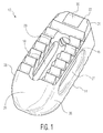
- Implant 10 is shown as an implant suitable for implantation from a posterior approach.
- the present invention is not limited to any particular type of implant design. Rather, it is contemplated that certain features of the present invention can be implemented in different types of implants. For instance, implants according to the present invention can be adapted for implantation from anterior or lateral aspects of the patient, as will be discussed below.
- implants according to the present invention can be constructed of polymeric materials such as PEEK or the like.
- each of the embodiments shown in the drawings are designed for placement between adjacent vertebral bodies. However, it is contemplated that implants in accordance with the present invention may be designed for use as vertebral body replacements.
- Implant 10 is shown including upper and lower surfaces 12 and 14, respectively. Each surface includes a plurality of serrations 16 at least covering a portion of the surface. While a specific serration design is depicted in the drawings and described in more detail below, many different serration designs can be employed. Implant 10 also includes a cavity 18 formed through a central portion of the implant and each of surfaces 12 and 14. Cavity 18 can be sized and shaped differently from what is shown and can be located in other locations of implant 10. Cavity 18 is preferably designed so that bone growth promoting materials can be contained therein to promote bone growth through the implant.
- Implant 10 also includes a wedge nose 20, a rear end 22 with a threaded opening 24 and a chamfer interface 25, and sidewalls 26 and 28 through which lateral windows 27 and 29, respectively are formed.
- Wedge nose 20 is sized and shaped so as to distract vertebral bodies during insertion of the implant into the intervertebral space.
- Threaded opening 24 and chamfer interface 25 are configured to cooperate with an insertion tool (not shown in detail).
- Lateral windows 27 and 29 act to both reduce the stiffness of implant 10 and allow for visualization through the lateral aspect of the implant under fluoroscopy imaging.
- the specific sizes and shapes of these elements may vary in other embodiment implants in accordance with the present invention, including certain embodiments discussed below. For instance, certain of the surfaces of implant 10 are shown as smooth and rounded to reduce the potential for soft tissue damage during an implantation procedure, but can be configured differently.
- Implant 10 is formed of both solid and porous portions.
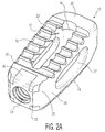
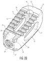
- the porous portions are located on upper and lower surfaces 12, 14, as well as on certain of the internal surfaces of the implant, which allows for bone to grow into a significant portion of the implant. This can best be seen in Figures 2B, 4B, 8B, and 9A-9C , where the porous surfaces of implant 10 are shown with different shading.
- the porous surfaces have an average pore diameter between 100-1000 microns with a 30-80% porosity, while a preferred embodiment would have a porosity between 55-65%.
- the porous surfaces may also have any thickness, for instance between 500-4500 microns, and preferably between 500-1500 microns.
- porous portions of implant 10 can be created through the use of a 3D printing process such as is disclosed in U.S. Patent Nos. 7,537,664 and 8,147,861 ; U.S. Patent Application Publications Nos. 2006/0147332 , 2007/0142914 , 2008/0004709 ; and U.S. Patent Application Serial Nos. 13/441,154 and 13/618,218 , the disclosures of which are hereby incorporated by reference herein. It is also contemplated to form any porous portion via another known or hereafter developed procedure, such as laser etching.
- FIG. 2B, 4B and 6-8B the location of the porous and solid portions of implant 10 will be discussed.
- the porous portions of the implant are shown as darker sections, while the solid portions are depicted in lighter material.
- the cross-sectional views of Figures 6-8B depict these portions with different cross hatching.
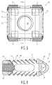
- nose 20 includes a solid, smooth exterior construction. The use of solid metal in this section allows for it to withstand impaction loads during an insertion process, as well as for visualization of its location under fluoroscopy or other imaging. It is shown in Figure 6 that nose 20 in actuality includes a solid portion 30, a hollow area 32 and a porous region 34.
- Solid portion 30 is designed to provide the necessary support discussed above, while hollow area 32 is provided in order to decrease the radioopacity of the nose and improve visualization under fluoroscopy imaging.
- Porous region 34 extends into the area within cavity 18. It is contemplated that in other embodiments, porous region 34 may extend partially or completely into hollow area 32. This still acts to decrease the radioopacity of the nose, which improves visualization, but also improve the cleanability, sterilization and powder removal from the implant during processing.
- rear end 22 is formed of solid material, so as to facilitate a strong connection with an insertion tool (not shown in detail).
- sections 36 are formed solid as they overlie threaded opening 24. This construction adds the necessary stability to the opening that is required for a solid connection with the insertion tool.
- side walls 26, 28 are, as is best shown in Figures 8A and 8B , formed solid on an exterior of implant 10 and porous in an interior thereof. Specifically, with reference to Figure 8B , the side walls include solid portions 38 and porous portions 40. Again, the inclusion of solid portions 38 provides stability to implant 10.
- Solid portions 38 may be any thickness, for instance, within the range of 0.25mm to 0.5mm.
- the solid portions also serve to provide a smooth exterior surface to the implant, which reduces tissue damage during implantation. It is noted that in certain embodiments, material may be machined off of any of the surfaces to create a smooth surface finish, which may further prevent tissue damage during implantation. This is especially true in connection with implanted formed by 3D printing processes, as such often result in even solid portions having a rougher surface finish.
- serrations 16 include solid tips 40 and solid roots 42, with the remainder of their construction including porous sections 44.
- Solid tips 40 not only provide a strong leading surface for engagement with bone, but also prevent fracture of a porous surface from occurring upon such engagement.
- the individual components (e.g., struts) of the porous surfaces of implant 10 may not necessarily converge to a point, they may fracture upon application of a force like what would be transmitted to serrations 16 during implantation.
- Solid core 42 also acts to strengthen serrations 16, by essentially providing a strong foundation for porous sections 44.
- serrations 16 are also designed to create a strong initial implant-bone connection, while also allowing for easy insertion of implant 10 into the space between vertebrae.
- serrations 16 are oriented at an angle 46 ( see figure 7 ). This angle may be any value, although a value within the range of 60 to 80 degrees is preferable.
- the angle 48 ( see figure 7 ) of solid tips 40 is preferably in the range of 30 to 50 degrees.
- the height 50 of serrations 60 may be within the range of 0.5mm to 1.5mm, while the height 52 of solid tips 40 is dependent upon height 50, but preferably is within the range of 0.25mm to 0.5mm.
- Solid core 42 has a thickness 54, preferably 0.1mm to 0.3mm thick.
- the overall pitch 56 of serrations 16 is preferably between 1.25mm and 2mm.
- FIG. 9A-9C A fully constructed implant 10 is depicted in Figures 9A-9C . As shown, the various solid and porous portions of the implant appear differently to the naked eye. The particular prototype shown in those figures was created via a 3D printing process referred to as additive manufacturing, utilizing a titanium material.
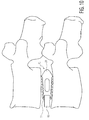
- Figure 10 is a fluoroscopic image of implant 10 while in position between two adjacent vertebral bodies. In the particular image shown there, implant 10 is engaged with an insertion tool 60, although the specifics of that tool cannot be seen.
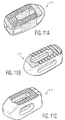
- Figures 11A-11C depict different embodiment implants 110, 210 and 310, respectively that are each suitable for implantation from a posterior approach, like implant 10.
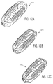
- Figures 12A-12C depict different embodiment implants 410, 510 and 610, respectively that are each suitable for implantation from a lateral approach.
- Figures 13A-13B depict an implant 710 suitable for implantation from a posterior lateral approach.
- Figures 14A-14B depict an implant 810 suitable for implantation from an anterior approach.
- those implants differ from implant 10 and each other in the manner in which their solid and porous portions are dispersed throughout the design. Again, solid portions are shown in lighter shading and porous portions are shown in darker shading.
- Figures 15A-15C depict an implant 910 similar to that of implant 10, albeit with certain specific differences.
- nose 920 includes sidewalls (best shown in Fig. 15A ) that exhibit an increased angle from that of nose 20.
- This particular design allows for the implant to be inserted in an orientation that is rotated ninety degrees from the traditional insertion orientation of such an implant. Thereafter, implant 910 is rotated, which may result in an additional distraction from that of the initial insertion.
- Implant 910 may also be provided with a feature, such as a dimple or the like (not shown), that helps to identify the correct final orientation of the implant.
- a dimple may be provided at rear end 922 so that the surgeon may easily identify the final orientation of the implant.
- any visual identifier could also be employed.
- Implant 910 also includes differently shaped/oriented lateral windows 927, 929 (only window 929 is shown in Fig. 15B ) from that of above-discussed windows 27, 29. As shown, windows 927, 929 extend along less of implant 910 than do windows 27, 29 along implant 10. Moreover, the height of windows 927, 929 taper in the same direction as does the height of implant 910. For implants that are not lordotic, the windows may be a constant height. Finally, implant 910 exhibits chamfered edges 923 (best shown in Fig. 15C ) that are on the four sides of the implant to eliminate sharp edges an make the implant more suitable for implantation without tissue damage.
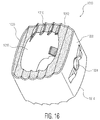
- FIG 16 depicts yet another embodiment according to the present invention, cervical implant 1010.
- This implant is particularly suited for implantation in a cervical area of the spine and includes many elements similar to those of the other embodiment implants.
- implant 1010 includes upper and lower surfaces 1012, 1014 which include serrations 1016 similar to those discussed above.
- the cervical implant includes a tapered nose or leading end 1020 and a trailing end 1022 with an aperture 1024 for engaging an insertion tool.
- implant 1010 is shown as having porous portions at the upper and lower surfaces 1012, 1014 that are similar to those discussed above.
- the various implants in accordance with the present invention may be implanted in a manner similar to existing spinal implants.
- an insertion tool e.g., tool 60
- the implant may be coupled with the implant to guide the implant into place between vertebral bodies.
- Initial engagement of the implant with the vertebral bodies is achieved via mechanical coupling elements included on the implant (e.g., serrations 16).
- bone is permitted to grow into any porous sections on the implant. This bone growth may be promoted through the use of bone growth promoting substances, such as allograft materials placed within cavity 18.
- the porosity of the implant preferably allows for a stronger fusion than that of existing, nonporous implants.
- the aforementioned 3D printing process can be utilized (see e.g., Figures 9A-9C ). Because of the construction of the implant, it may be beneficial to orient the construction in one manner or the like. For instance, it has been found that orienting the build so that nose 20 faces down ( i.e., is built first) results in better serration 16 creation. Of course, the nose down orientation is only one of many that can be employed and the creation of implants according to the present invention is not to be so limited.
Abstract
Description
- The present application claims the benefit of the filing date of
U.S. Provisional Patent Application No. 62/103,276, filed January 14, 2015 - The present invention relates to spinal surgery, namely, implants utilized in fusing adjacent intervertebral bodies or the replacement of a vertebral body.
- Back pain can be caused by many different maladies, not the least of which are problems that directly impact the intervertebral discs of the spine. Typical disc issues include, inter alia, degeneration, bulging, herniation, thinning and abnormal movement. One method of treatment of such disc problems that has been widely utilized in the field of spinal surgery is a spinal fusion procedure, whereby an affected disc is removed, and the adjacent vertebral bodies are fused together through the use of interbody spacers, implants or the like. In some instances, it may also be necessary to remove and replace an entire vertebral body. This is often accomplished through the use of a larger implant that acts to fuse together the vertebral bodies adjacent the removed vertebral body.
- The aforementioned implants often rely upon mechanical features to ensure engagement between the devices and the bone of the existing vertebral bodies. This coupled with the normal compressive load of the spine acts to keep the implant in place until bone can grow from the existing vertebral bodies into and through the implant. To encourage the bone growth, the implants are often pre-loaded with bone growth promoting material and thereafter placed into the spine. Bone growth promoting material may include naturally occurring bone, artificial materials or the like.
- To further ensure a strong implant-bone connection, some existing implants include an area formed of porous material that allows bone to grow into it. Although there is little doubt that the bone growth into the implant is beneficial in maintaining an implant in place, these implants are often very difficult (and thusly, expensive) to manufacture. Additionally, existing implants that implement porous material do so in a limited manner. Often times, because of manufacturing or strength concerns or the like, the porous material is limited to a thin layer covering the upper and lower surfaces of the implant, which only allows for a small amount of bone to grow into the implant.
- Therefore, there exists a need for an improved spinal implant that employs a significant amount of porous material, yet remains cost efficient and maintains the necessary strength required of a spinal implant.
- A first aspect of the present invention is a spinal implant including an upper surface including a first porous portion and first solid portion, a lower surface including a second porous portion and a second solid portion and a cavity formed through the upper and lower surfaces, the cavity including a third porous portion.
- Other embodiments according to the first aspect may include a nose having a solid exterior, a hollow area and a porous region. At least one serration may be included on each of the upper and lower surfaces. The serration(s) may include a solid tip, a solid root and a porous section. The implant may further include first and second side walls extending between the upper and lower surfaces, the side walls including a solid exterior surface and a porous interior surface. The first and second side walls may each include lateral windows. The lateral windows may reduce the stiffness of the implant and may be tapered. The implant may also include a threaded opening at a rear end. Implants according to the present invention may be constructed of any material suitable for implantation in the body of a patient, for instance, a metal such as titanium. The implants can be configured for insertion from various aspects, e.g., a posterior approach, a lateral approach or an anterior approach. The implant may include a nose that facilitates the insertion of the implant in a first orientation and rotation to a second orientation. The implant may be constructed from an additive manufacturing process, and may be machined to create smooth surfaces.
- A more complete appreciation of the subject matter of the present invention and of the various advantages thereof can be realized by reference to the following detailed description in which reference is made to the accompanying drawings in which:
-
Figure 1 is a front perspective view of an implant according to one embodiment of the present invention. -
Figures 2A and2B are rear perspective views of the implant offigure 1 . -
Figure 3 is a side view of the implant offigure 1 . -
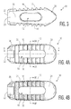
Figures 4A and 4B are top views of the implant offigure 1 . -
Figure 5 is a rear view of the implant offigure 1 . -
Figure 6 is a cross-sectional view of the implant offigure 1 take along line 6-6 offigure 5 . -
Figure 7 is an enlarged cross-sectional view of serrations of the implant offigure 1 . -
Figures 8A-8B are cross-sectional views of the implant offigure 1 take alonglines 8A-8A and 8B-8B offigures 4A and 4B , respectively. -
Figures 9A-9C are views illustrating a constructed version of the implant offigure 1 . -
Figure 10 is a fluoroscopic view of an implanted implant offigure 1 . -
Figures 11A-11C are views of implants according to other embodiments of the present invention. -
Figures 12A-12C are views of implants according to other embodiments of the present invention. -
Figures 13A-13B are views of implants according to other embodiments of the present invention. -
Figures 14A-14B are views of implants according to other embodiments of the present invention. -
Figures 15A-15C are views of implants according to other embodiments of the present invention. -
Figure 16 depicts yet another implant according to another embodiment of the present invention. - An
implant 10 according to a first embodiment of the present invention is depicted inFigures 1-10 .Implant 10 is shown as an implant suitable for implantation from a posterior approach. However, as will be readily apparent from the below discussion pertaining to other embodiments, the present invention is not limited to any particular type of implant design. Rather, it is contemplated that certain features of the present invention can be implemented in different types of implants. For instance, implants according to the present invention can be adapted for implantation from anterior or lateral aspects of the patient, as will be discussed below. Moreover, although disclosed as being constructed of metallic materials, it is contemplated that implants according to the present invention may be constructed of polymeric materials such as PEEK or the like. Additionally, each of the embodiments shown in the drawings are designed for placement between adjacent vertebral bodies. However, it is contemplated that implants in accordance with the present invention may be designed for use as vertebral body replacements. -
Implant 10 is shown including upper andlower surfaces serrations 16 at least covering a portion of the surface. While a specific serration design is depicted in the drawings and described in more detail below, many different serration designs can be employed.Implant 10 also includes acavity 18 formed through a central portion of the implant and each ofsurfaces Cavity 18 can be sized and shaped differently from what is shown and can be located in other locations ofimplant 10.Cavity 18 is preferably designed so that bone growth promoting materials can be contained therein to promote bone growth through the implant. -
Implant 10 also includes awedge nose 20, arear end 22 with a threadedopening 24 and achamfer interface 25, andsidewalls lateral windows Wedge nose 20 is sized and shaped so as to distract vertebral bodies during insertion of the implant into the intervertebral space. Threadedopening 24 andchamfer interface 25 are configured to cooperate with an insertion tool (not shown in detail).Lateral windows implant 10 and allow for visualization through the lateral aspect of the implant under fluoroscopy imaging. Of course, the specific sizes and shapes of these elements may vary in other embodiment implants in accordance with the present invention, including certain embodiments discussed below. For instance, certain of the surfaces ofimplant 10 are shown as smooth and rounded to reduce the potential for soft tissue damage during an implantation procedure, but can be configured differently. -
Implant 10 is formed of both solid and porous portions. The porous portions are located on upper andlower surfaces Figures 2B, 4B, 8B, and 9A-9C , where the porous surfaces ofimplant 10 are shown with different shading. In one embodiment, the porous surfaces have an average pore diameter between 100-1000 microns with a 30-80% porosity, while a preferred embodiment would have a porosity between 55-65%. The porous surfaces may also have any thickness, for instance between 500-4500 microns, and preferably between 500-1500 microns. This results in a surface that is both strong enough for use in a spinal implant and maximizes bone growth potential. The porous portions ofimplant 10, as well as the solid portions, can be created through the use of a 3D printing process such as is disclosed inU.S. Patent Nos. 7,537,664 and8,147,861 ;U.S. Patent Application Publications Nos. 2006/0147332 ,2007/0142914 ,2008/0004709 ; andU.S. Patent Application Serial Nos. 13/441,154 and13/618,218 - With specific reference to
Figures 2B, 4B and 6-8B , the location of the porous and solid portions ofimplant 10 will be discussed. In the solid model views ofFigures 2B and4B , the porous portions of the implant are shown as darker sections, while the solid portions are depicted in lighter material. The cross-sectional views ofFigures 6-8B on the other hand depict these portions with different cross hatching. For instance,nose 20 includes a solid, smooth exterior construction. The use of solid metal in this section allows for it to withstand impaction loads during an insertion process, as well as for visualization of its location under fluoroscopy or other imaging. It is shown inFigure 6 thatnose 20 in actuality includes asolid portion 30, ahollow area 32 and aporous region 34.Solid portion 30 is designed to provide the necessary support discussed above, whilehollow area 32 is provided in order to decrease the radioopacity of the nose and improve visualization under fluoroscopy imaging.Porous region 34, as will be discussed more fully below, extends into the area withincavity 18. It is contemplated that in other embodiments,porous region 34 may extend partially or completely intohollow area 32. This still acts to decrease the radioopacity of the nose, which improves visualization, but also improve the cleanability, sterilization and powder removal from the implant during processing. - Like
nose 20, a significant portion ofrear end 22 is formed of solid material, so as to facilitate a strong connection with an insertion tool (not shown in detail). In particular, it is noted that while certain portions of the upper andlower surfaces sections 36 are formed solid as they overlie threadedopening 24. This construction adds the necessary stability to the opening that is required for a solid connection with the insertion tool. Moreover,side walls Figures 8A and 8B , formed solid on an exterior ofimplant 10 and porous in an interior thereof. Specifically, with reference toFigure 8B , the side walls includesolid portions 38 andporous portions 40. Again, the inclusion ofsolid portions 38 provides stability to implant 10. However, as is mentioned above,lateral windows Solid portions 38 may be any thickness, for instance, within the range of 0.25mm to 0.5mm. The solid portions also serve to provide a smooth exterior surface to the implant, which reduces tissue damage during implantation. It is noted that in certain embodiments, material may be machined off of any of the surfaces to create a smooth surface finish, which may further prevent tissue damage during implantation. This is especially true in connection with implanted formed by 3D printing processes, as such often result in even solid portions having a rougher surface finish. - Aside from the above discussed portions that are formed solid, the majority of the remainder of
implant 10 is formed porous. Most notably, upper andlower surfaces portions having serrations 16. However, the serrations themselves include some solid portions. With reference tofigures 6 and7 ,serrations 16 includesolid tips 40 andsolid roots 42, with the remainder of their construction includingporous sections 44.Solid tips 40 not only provide a strong leading surface for engagement with bone, but also prevent fracture of a porous surface from occurring upon such engagement. Specifically, since the individual components (e.g., struts) of the porous surfaces ofimplant 10 may not necessarily converge to a point, they may fracture upon application of a force like what would be transmitted toserrations 16 during implantation.Solid core 42 also acts to strengthenserrations 16, by essentially providing a strong foundation forporous sections 44. - The particular shape of
serrations 16 is also designed to create a strong initial implant-bone connection, while also allowing for easy insertion ofimplant 10 into the space between vertebrae. In order to resist back-out ofimplant 10,serrations 16 are oriented at an angle 46 (seefigure 7 ). This angle may be any value, although a value within the range of 60 to 80 degrees is preferable. The angle 48 (seefigure 7 ) ofsolid tips 40 is preferably in the range of 30 to 50 degrees. Theheight 50 ofserrations 60 may be within the range of 0.5mm to 1.5mm, while theheight 52 ofsolid tips 40 is dependent uponheight 50, but preferably is within the range of 0.25mm to 0.5mm.Solid core 42 has athickness 54, preferably 0.1mm to 0.3mm thick. Theoverall pitch 56 ofserrations 16 is preferably between 1.25mm and 2mm. - The interior of
cavity 18 is largely constructed of porous material, which allows for bone growth in this section as well, and hence fusion throughimplant 10. This construction has the added benefit of also reducing stiffness of the implant, likelateral windows implant 10 is depicted inFigures 9A-9C . As shown, the various solid and porous portions of the implant appear differently to the naked eye. The particular prototype shown in those figures was created via a 3D printing process referred to as additive manufacturing, utilizing a titanium material.Figure 10 is a fluoroscopic image ofimplant 10 while in position between two adjacent vertebral bodies. In the particular image shown there,implant 10 is engaged with aninsertion tool 60, although the specifics of that tool cannot be seen. -
Figures 11A-11C depictdifferent embodiment implants implant 10.Figures 12A-12C depictdifferent embodiment implants Figures 13A-13B depict animplant 710 suitable for implantation from a posterior lateral approach.Figures 14A-14B depict animplant 810 suitable for implantation from an anterior approach. Among other ways, those implants differ fromimplant 10 and each other in the manner in which their solid and porous portions are dispersed throughout the design. Again, solid portions are shown in lighter shading and porous portions are shown in darker shading. These various implant embodiments demonstrate that implants in accordance with the present invention may vary both in their size and shape, as well as in the configuration of their porous and solid portions. -
Figures 15A-15C depict animplant 910 similar to that ofimplant 10, albeit with certain specific differences. For instance,nose 920 includes sidewalls (best shown inFig. 15A ) that exhibit an increased angle from that ofnose 20. This particular design allows for the implant to be inserted in an orientation that is rotated ninety degrees from the traditional insertion orientation of such an implant. Thereafter,implant 910 is rotated, which may result in an additional distraction from that of the initial insertion.Implant 910 may also be provided with a feature, such as a dimple or the like (not shown), that helps to identify the correct final orientation of the implant. For instance, a dimple may be provided atrear end 922 so that the surgeon may easily identify the final orientation of the implant. Of course, any visual identifier could also be employed. -
Implant 910 also includes differently shaped/oriented lateral windows 927, 929 (onlywindow 929 is shown inFig. 15B ) from that of above-discussedwindows windows 927, 929 extend along less ofimplant 910 than dowindows implant 10. Moreover, the height ofwindows 927, 929 taper in the same direction as does the height ofimplant 910. For implants that are not lordotic, the windows may be a constant height. Finally, implant 910 exhibits chamfered edges 923 (best shown inFig. 15C ) that are on the four sides of the implant to eliminate sharp edges an make the implant more suitable for implantation without tissue damage. -
Figure 16 depicts yet another embodiment according to the present invention,cervical implant 1010. This implant is particularly suited for implantation in a cervical area of the spine and includes many elements similar to those of the other embodiment implants. For instance,implant 1010 includes upper andlower surfaces serrations 1016 similar to those discussed above. Further, the cervical implant includes a tapered nose or leadingend 1020 and a trailing end 1022 with anaperture 1024 for engaging an insertion tool. Although other embodiments may vary,implant 1010 is shown as having porous portions at the upper andlower surfaces - In use, the various implants in accordance with the present invention may be implanted in a manner similar to existing spinal implants. For instance, an insertion tool (e.g., tool 60) may be coupled with the implant to guide the implant into place between vertebral bodies. Initial engagement of the implant with the vertebral bodies is achieved via mechanical coupling elements included on the implant (e.g., serrations 16). Thereafter, bone is permitted to grow into any porous sections on the implant. This bone growth may be promoted through the use of bone growth promoting substances, such as allograft materials placed within
cavity 18. After some time, the porosity of the implant preferably allows for a stronger fusion than that of existing, nonporous implants. - In creating an implant such as
implant 10, the aforementioned 3D printing process can be utilized (see e.g.,Figures 9A-9C ). Because of the construction of the implant, it may be beneficial to orient the construction in one manner or the like. For instance, it has been found that orienting the build so thatnose 20 faces down (i.e., is built first) results inbetter serration 16 creation. Of course, the nose down orientation is only one of many that can be employed and the creation of implants according to the present invention is not to be so limited. - Although the invention herein has been described with reference to particular embodiments, it is to be understood that these embodiments are merely illustrative of the principles and applications of the present invention. It is therefore to be understood that numerous modifications may be made to the illustrative embodiments and that other arrangements may be devised without departing from the spirit and scope of the present invention as defined by the appended claims.
Claims (15)
- A spinal implant comprising:an upper surface including a first porous portion and first solid portion;a lower surface including a second porous portion and a second solid portion; anda cavity formed through the upper and lower surfaces, the cavity including a third porous portion.
- The spinal implant of claim 1, further including a nose having a solid exterior, a hollow area and a porous region.
- The spinal implant of claim 1, further including at least one serration on each of the upper and lower surfaces, the at least one serration including a solid tip, a solid root and a porous section.
- The spinal implant of claim 1, further including first and second side walls extending between the upper and lower surfaces, the side walls including a solid exterior surface and a porous interior surface.
- The spinal implant of claim 4, wherein the first and second side walls each include lateral windows.
- The spinal implant of claim 5, wherein the lateral windows reduce the stiffness of the implant.
- The spinal implant of claim 6, wherein the lateral windows taper.
- The spinal implant of claim 1, further comprising a threaded opening at a rear end.
- The spinal implant of claim 1, wherein the implant is constructed of a metal.
- The spinal implant of claim 9, wherein the metal is titanium.
- The spinal implant of claim 1, wherein the implant is configured for insertion from a posterior approach, a lateral approach or an anterior approach.
- The spinal implant of claim 1, further including a nose that facilitates the insertion of the implant in a first orientation and rotation to a second orientation.
- The spinal implant of claim 12, wherein the nose has a solid exterior.
- The spinal implant of claim 1, wherein the implant is constructed from an additive manufacturing process.
- The spinal implant of claim 14, wherein the implant is machined to create smooth surfaces.
Priority Applications (1)
| Application Number | Priority Date | Filing Date | Title |
|---|---|---|---|
| EP19213674.5A EP3636224B1 (en) | 2015-01-14 | 2016-01-14 | Spinal implant with porous and solid surfaces |
Applications Claiming Priority (1)
| Application Number | Priority Date | Filing Date | Title |
|---|---|---|---|
| US201562103276P | 2015-01-14 | 2015-01-14 |
Related Child Applications (1)
| Application Number | Title | Priority Date | Filing Date |
|---|---|---|---|
| EP19213674.5A Division EP3636224B1 (en) | 2015-01-14 | 2016-01-14 | Spinal implant with porous and solid surfaces |
Publications (2)
| Publication Number | Publication Date |
|---|---|
| EP3045151A1 true EP3045151A1 (en) | 2016-07-20 |
| EP3045151B1 EP3045151B1 (en) | 2020-01-01 |
Family
ID=55129796
Family Applications (2)
| Application Number | Title | Priority Date | Filing Date |
|---|---|---|---|
| EP19213674.5A Active EP3636224B1 (en) | 2015-01-14 | 2016-01-14 | Spinal implant with porous and solid surfaces |
| EP16151375.9A Active EP3045151B1 (en) | 2015-01-14 | 2016-01-14 | Spinal implant with porous and solid surfaces |
Family Applications Before (1)
| Application Number | Title | Priority Date | Filing Date |
|---|---|---|---|
| EP19213674.5A Active EP3636224B1 (en) | 2015-01-14 | 2016-01-14 | Spinal implant with porous and solid surfaces |
Country Status (5)
| Country | Link |
|---|---|
| US (3) | US10182923B2 (en) |
| EP (2) | EP3636224B1 (en) |
| JP (2) | JP6760733B2 (en) |
| AU (3) | AU2016200179B2 (en) |
| CA (2) | CA3019699C (en) |
Cited By (4)
| Publication number | Priority date | Publication date | Assignee | Title |
|---|---|---|---|---|
| WO2018165571A1 (en) * | 2017-03-10 | 2018-09-13 | Life Spine, Inc. (A Delaware Corporation) | 3-d printed orthopedic implants |
| EP3459502A1 (en) * | 2017-09-20 | 2019-03-27 | Stryker European Holdings I, LLC | Spinal implants |
| EP3662870A1 (en) * | 2018-12-05 | 2020-06-10 | SMed - TA/TD LLC | Adjusted stiffness orthopaedic implants and method of manufacture |
| WO2021216856A1 (en) * | 2020-04-23 | 2021-10-28 | Rv Medical Llc | Screwless interbody device for spinal surgery |
Families Citing this family (70)
| Publication number | Priority date | Publication date | Assignee | Title |
|---|---|---|---|---|
| EP3744509B1 (en) | 2012-08-21 | 2022-03-23 | Vertera Inc. | Method for making porous articles |
| FR3006170B1 (en) * | 2013-05-31 | 2015-06-26 | Osd Orthopaedic & Spine Dev | INTERSOMATIC PROSTHESIS PRODUCING INDIVIDUALIZED LORDOSE SETTING |
| US10292833B2 (en) * | 2013-11-27 | 2019-05-21 | Howmedica Osteonics Corp. | Structurally supporting insert for spinal fusion cage |
| US9504550B2 (en) | 2014-06-26 | 2016-11-29 | Vertera, Inc. | Porous devices and processes for producing same |
| US9498922B2 (en) | 2014-06-26 | 2016-11-22 | Vertera, Inc. | Apparatus and process for producing porous devices |
| EP3050540B1 (en) | 2015-01-27 | 2022-04-20 | K2M, Inc. | Spinal implant |
| US10028841B2 (en) * | 2015-01-27 | 2018-07-24 | K2M, Inc. | Interbody spacer |
| US10449051B2 (en) | 2015-04-29 | 2019-10-22 | Institute for Musculoskeletal Science and Education, Ltd. | Implant with curved bone contacting elements |
| JP6768001B2 (en) | 2015-04-29 | 2020-10-14 | インスティテュート フォー マスキュロスケレタル サイエンス アンド エジュケイション,リミテッド | Coiled implants and systems and how to make them |
| USD815281S1 (en) | 2015-06-23 | 2018-04-10 | Vertera, Inc. | Cervical interbody fusion device |
| JP6943598B2 (en) * | 2016-04-07 | 2021-10-06 | ハウメディカ・オステオニクス・コーポレイション | Expandable interbody implant |
| JP2017205522A (en) | 2016-05-20 | 2017-11-24 | ハウメディカ・オステオニクス・コーポレイション | Expandable interbody implant for lordosis correction |
| US20200000595A1 (en) | 2016-06-07 | 2020-01-02 | HD LifeSciences LLC | High X-Ray Lucency Lattice Structures |
| US10292825B2 (en) * | 2016-06-27 | 2019-05-21 | Globus Medical, Inc. | Intervertebral spacer with chamfered edges |
| US10292834B2 (en) * | 2016-06-27 | 2019-05-21 | Globus Medical, Inc. | Intervertebral spacer with chamfered edges |
| JP6700135B2 (en) * | 2016-07-25 | 2020-05-27 | 日本特殊陶業株式会社 | Vertebral body spacer |
| US11166709B2 (en) | 2016-08-23 | 2021-11-09 | Stryker European Operations Holdings Llc | Instrumentation and methods for the implantation of spinal implants |
| US10478312B2 (en) | 2016-10-25 | 2019-11-19 | Institute for Musculoskeletal Science and Education, Ltd. | Implant with protected fusion zones |
| WO2018152077A1 (en) | 2017-02-14 | 2018-08-23 | HD LifeSciences LLC | High x-ray lucency lattice structures and variably x-ray licent markers |
| CA3061948A1 (en) * | 2017-02-24 | 2018-08-30 | HD LifeSciences LLC | Implant features, implants and methods of designing and manufacturing devices with a reduced volumetric density |
| US10905436B2 (en) | 2017-03-02 | 2021-02-02 | Optimotion Implants, Llc | Knee arthroplasty systems and methods |
| US11406502B2 (en) | 2017-03-02 | 2022-08-09 | Optimotion Implants LLC | Orthopedic implants and methods |
| US10512549B2 (en) | 2017-03-13 | 2019-12-24 | Institute for Musculoskeletal Science and Education, Ltd. | Implant with structural members arranged around a ring |
| US10357377B2 (en) | 2017-03-13 | 2019-07-23 | Institute for Musculoskeletal Science and Education, Ltd. | Implant with bone contacting elements having helical and undulating planar geometries |
| US10888429B2 (en) | 2017-04-01 | 2021-01-12 | HD LifeSciences LLC | Three-dimensional lattice structures for implants |
| CA3058777A1 (en) | 2017-04-01 | 2018-10-04 | HD LifeSciences LLC | Fluid interface system for implants |
| US11672674B2 (en) * | 2017-04-19 | 2023-06-13 | Life Spine Inc. | Implant with bone screw retention |
| WO2019051260A1 (en) * | 2017-09-08 | 2019-03-14 | Pioneer Surgical Technology, Inc. | Intervertebral implants, instruments, and methods |
| US11801144B2 (en) * | 2017-09-14 | 2023-10-31 | Degen Medical, Inc. | Methods of making medical devices |
| USD907771S1 (en) | 2017-10-09 | 2021-01-12 | Pioneer Surgical Technology, Inc. | Intervertebral implant |
| MX2020004189A (en) * | 2017-10-20 | 2020-10-14 | Centinel Spine Llc | Porous implantable interbody devices. |
| US10736752B1 (en) | 2017-10-24 | 2020-08-11 | Omnia Medical, LLC | Multi-material multi-component spinal implant |
| US11766339B1 (en) | 2017-10-24 | 2023-09-26 | Omnia Medical, LLC | Multi-material multi-component spinal implant |
| US10744001B2 (en) | 2017-11-21 | 2020-08-18 | Institute for Musculoskeletal Science and Education, Ltd. | Implant with improved bone contact |
| US11039933B2 (en) | 2017-12-15 | 2021-06-22 | Innovasis, Inc. | Interbody spinal fusion implant with support struts |
| EP3593745A3 (en) | 2018-02-02 | 2020-04-01 | Stryker European Holdings I, LLC | Orthopedic screw and porous structures thereof |
| USD870890S1 (en) | 2018-03-02 | 2019-12-24 | Restor3D, Inc. | Spiral airway stent |
| US10183442B1 (en) | 2018-03-02 | 2019-01-22 | Additive Device, Inc. | Medical devices and methods for producing the same |
| USD871577S1 (en) | 2018-03-02 | 2019-12-31 | Restor3D, Inc. | Studded airway stent |
| USD870889S1 (en) | 2018-03-02 | 2019-12-24 | Restor3D, Inc. | Cutout airway stent |
| USD870888S1 (en) | 2018-03-02 | 2019-12-24 | Restor3D, Inc. | Accordion airway stent |
| EP3545857B1 (en) | 2018-03-30 | 2024-01-03 | Stryker European Operations Holdings LLC | Lateral access retractor and core insertion |
| JP2019180797A (en) * | 2018-04-09 | 2019-10-24 | 日本特殊陶業株式会社 | Vertebral body spacer |
| US10524927B2 (en) | 2018-05-08 | 2020-01-07 | Globus Medical, Inc. | Intervertebral spinal implant |
| US10682238B2 (en) | 2018-05-08 | 2020-06-16 | Globus Medical, Inc. | Intervertebral spinal implant |
| US10744003B2 (en) | 2018-05-08 | 2020-08-18 | Globus Medical, Inc. | Intervertebral spinal implant |
| FR3082449B1 (en) * | 2018-06-15 | 2020-09-04 | Safran Landing Systems | PROCESS FOR MAKING A PART WITH CAVITY BY ADDITIVE MANUFACTURING |
| JP2021531894A (en) | 2018-07-26 | 2021-11-25 | エイチディー ライフサイエンシズ エルエルシーHd Lifesciences Llc | Dynamic implant fixation plate |
| EP3603580B1 (en) * | 2018-08-02 | 2023-12-06 | Globus Medical, Inc. | Intervertebral spinal implants |
| AU2019213392A1 (en) | 2018-08-09 | 2020-02-27 | Stryker European Operations Holdings, LLC | Interbody implants and optimization features thereof |
| US11497617B2 (en) | 2019-01-16 | 2022-11-15 | Nanohive Medical Llc | Variable depth implants |
| US11039931B2 (en) | 2019-02-01 | 2021-06-22 | Globus Medical, Inc. | Intervertebral spinal implant |
| US20200281736A1 (en) | 2019-03-04 | 2020-09-10 | K2M, Inc. | Intervertebral Implant Assembly and Instruments Therefor |
| US11213403B2 (en) | 2019-03-14 | 2022-01-04 | Medos International Sarl | Devices and methods for optimized spinal fixation |
| US10889053B1 (en) | 2019-03-25 | 2021-01-12 | Restor3D, Inc. | Custom surgical devices and method for manufacturing the same |
| US11173043B1 (en) | 2019-05-17 | 2021-11-16 | Joseph T. Robbins | Spinal interbody implants |
| USD930160S1 (en) * | 2019-09-11 | 2021-09-07 | L&K Biomed Co., Ltd. | End plate for a spinal fusion cage |
| USD929594S1 (en) * | 2019-09-11 | 2021-08-31 | L&K Biomed Co., Ltd. | End plate for a spinal fusion cage |
| US11564674B2 (en) | 2019-11-27 | 2023-01-31 | K2M, Inc. | Lateral access system and method of use |
| USD950060S1 (en) * | 2019-12-24 | 2022-04-26 | PrinterPrezz, Inc. | Posterior lumbar interbody fusion device |
| USD920517S1 (en) | 2020-01-08 | 2021-05-25 | Restor3D, Inc. | Osteotomy wedge |
| US10772732B1 (en) | 2020-01-08 | 2020-09-15 | Restor3D, Inc. | Sheet based triply periodic minimal surface implants for promoting osseointegration and methods for producing same |
| USD920516S1 (en) | 2020-01-08 | 2021-05-25 | Restor3D, Inc. | Osteotomy wedge |
| USD920515S1 (en) | 2020-01-08 | 2021-05-25 | Restor3D, Inc. | Spinal implant |
| US11850158B2 (en) | 2020-05-26 | 2023-12-26 | Howmedica Osteonics Corp. | Orthopedic surgical implant device with porous material and fluid channels for cleaning the porous material |
| IT202000014587A1 (en) * | 2020-06-18 | 2021-12-18 | Sps S R L | INTERSOMATIC CAGE FOR VERTEBRAL STABILIZATION |
| KR102506660B1 (en) * | 2020-11-30 | 2023-03-06 | 주식회사 에이스메디코프 | Cage for spinal fusion surgery |
| JP7200425B1 (en) | 2022-06-06 | 2023-01-06 | HOYA Technosurgical株式会社 | Implantable device |
| US11850144B1 (en) | 2022-09-28 | 2023-12-26 | Restor3D, Inc. | Ligament docking implants and processes for making and using same |
| US11806028B1 (en) | 2022-10-04 | 2023-11-07 | Restor3D, Inc. | Surgical guides and processes for producing and using the same |
Citations (11)
| Publication number | Priority date | Publication date | Assignee | Title |
|---|---|---|---|---|
| US20060147332A1 (en) | 2004-12-30 | 2006-07-06 | Howmedica Osteonics Corp. | Laser-produced porous structure |
| US20070142914A1 (en) | 2005-12-06 | 2007-06-21 | Eric Jones | Laser-produced porous surface |
| US20080004709A1 (en) | 2005-12-30 | 2008-01-03 | Howmedica Osteonics Corp. | Laser-produced implants |
| US7537664B2 (en) | 2002-11-08 | 2009-05-26 | Howmedica Osteonics Corp. | Laser-produced porous surface |
| WO2010021612A1 (en) * | 2008-08-21 | 2010-02-25 | Warsaw Orthopedic, Inc. | Intervertebral implant with porous portions |
| US20110071635A1 (en) * | 2009-09-23 | 2011-03-24 | Zimmer Spine, Inc. | Composite implant |
| US8147861B2 (en) | 2006-08-15 | 2012-04-03 | Howmedica Osteonics Corp. | Antimicrobial implant |
| US20120265306A1 (en) * | 2011-04-14 | 2012-10-18 | Warsaw Orthopedic, Inc. | Spinal implant with attachable bone securing componet |
| WO2014018325A1 (en) * | 2012-07-25 | 2014-01-30 | Titan Spine, Llc | Implants having three distinct surfaces |
| DE202013007361U1 (en) * | 2013-03-22 | 2014-03-24 | Joimax Gmbh | Instrument set for inserting a basket into the disc space between two vertebral bodies |
| US20140277461A1 (en) * | 2013-03-15 | 2014-09-18 | Smed-Ta/Td, Llc | Porous tissue ingrowth structure |
Family Cites Families (368)
| Publication number | Priority date | Publication date | Assignee | Title |
|---|---|---|---|---|
| US3486505A (en) | 1967-05-22 | 1969-12-30 | Gordon M Morrison | Orthopedic surgical instrument |
| US3641590A (en) | 1970-01-16 | 1972-02-15 | Arthur A Michele | Acetabular replacement prosthesis and method of assembling |
| CA962806A (en) | 1970-06-04 | 1975-02-18 | Ontario Research Foundation | Surgical prosthetic device |
| US3852045A (en) | 1972-08-14 | 1974-12-03 | Battelle Memorial Institute | Void metal composite material and method |
| GB1551705A (en) | 1975-04-28 | 1979-08-30 | Downs Surgicial Ltd | Surgial implant |
| US4501269A (en) | 1981-12-11 | 1985-02-26 | Washington State University Research Foundation, Inc. | Process for fusing bone joints |
| CA1227902A (en) | 1984-04-02 | 1987-10-13 | Raymond G. Tronzo | Fenestrated hip screw and method of augmented internal fixation |
| US4612160A (en) | 1984-04-02 | 1986-09-16 | Dynamet, Inc. | Porous metal coating process and mold therefor |
| US4681589A (en) | 1984-06-01 | 1987-07-21 | Tronzo Raymond G | Adjustable acetabular cup prosthesis as part of a total cup replacement system |
| FR2570594B1 (en) | 1984-09-26 | 1989-02-24 | Kehr Pierre | VERTEBRAL PROSTHESIS, PARTICULARLY FOR CERVICAL VERTEBRES |
| CH665553A5 (en) * | 1985-02-07 | 1988-05-31 | Sulzer Ag | METAL BONE IMPLANT. |
| DE3637314A1 (en) | 1986-11-03 | 1988-05-11 | Lutz Biedermann | SPACE HOLDER IMPLANT |
| US4834757A (en) | 1987-01-22 | 1989-05-30 | Brantigan John W | Prosthetic implant |
| JPH01136655A (en) | 1987-11-24 | 1989-05-29 | Asahi Optical Co Ltd | Movable type pyramid spacer |
| CA1333209C (en) | 1988-06-28 | 1994-11-29 | Gary Karlin Michelson | Artificial spinal fusion implants |
| US5609635A (en) | 1988-06-28 | 1997-03-11 | Michelson; Gary K. | Lordotic interbody spinal fusion implants |
| CA1318469C (en) | 1989-02-15 | 1993-06-01 | Acromed Corporation | Artificial disc |
| US5458638A (en) | 1989-07-06 | 1995-10-17 | Spine-Tech, Inc. | Non-threaded spinal implant |
| FR2659226B1 (en) | 1990-03-07 | 1992-05-29 | Jbs Sa | PROSTHESIS FOR INTERVERTEBRAL DISCS AND ITS IMPLEMENTATION INSTRUMENTS. |
| DE4040106A1 (en) * | 1990-12-12 | 1992-06-17 | Mecron Med Prod Gmbh | SCENERY PROSTHESIS |
| US5192327A (en) | 1991-03-22 | 1993-03-09 | Brantigan John W | Surgical prosthetic implant for vertebrae |
| JP3007903B2 (en) | 1991-03-29 | 2000-02-14 | 京セラ株式会社 | Artificial disc |
| US5180381A (en) | 1991-09-24 | 1993-01-19 | Aust Gilbert M | Anterior lumbar/cervical bicortical compression plate |
| GB9125798D0 (en) | 1991-12-04 | 1992-02-05 | Customflex Limited | Improvements in or relating to spinal vertebrae implants |
| US5358533A (en) | 1992-02-19 | 1994-10-25 | Joint Medical Products Corporation | Sintered coatings for implantable prostheses |
| US5306309A (en) | 1992-05-04 | 1994-04-26 | Calcitek, Inc. | Spinal disk implant and implantation kit |
| US5370692A (en) | 1992-08-14 | 1994-12-06 | Guild Associates, Inc. | Rapid, customized bone prosthesis |
| US5723011A (en) | 1992-12-21 | 1998-03-03 | Zimmer, Inc. | Prosthetic implant and method of making same |
| US5425772A (en) * | 1993-09-20 | 1995-06-20 | Brantigan; John W. | Prosthetic implant for intervertebral spinal fusion |
| BE1007549A3 (en) * | 1993-09-21 | 1995-08-01 | Beckers Louis Francois Charles | Implant. |
| US5443514A (en) | 1993-10-01 | 1995-08-22 | Acromed Corporation | Method for using spinal implants |
| US5514180A (en) | 1994-01-14 | 1996-05-07 | Heggeness; Michael H. | Prosthetic intervertebral devices |
| US5443515A (en) | 1994-01-26 | 1995-08-22 | Implex Corporation | Vertebral body prosthetic implant with slidably positionable stabilizing member |
| US5431658A (en) | 1994-02-14 | 1995-07-11 | Moskovich; Ronald | Facilitator for vertebrae grafts and prostheses |
| CA2551185C (en) | 1994-03-28 | 2007-10-30 | Sdgi Holdings, Inc. | Apparatus and method for anterior spinal stabilization |
| US5504300A (en) | 1994-04-18 | 1996-04-02 | Zimmer, Inc. | Orthopaedic implant and method of making same |
| BE1008372A3 (en) | 1994-04-19 | 1996-04-02 | Materialise Nv | METHOD FOR MANUFACTURING A perfected MEDICAL MODEL BASED ON DIGITAL IMAGE INFORMATION OF A BODY. |
| US5885299A (en) | 1994-09-15 | 1999-03-23 | Surgical Dynamics, Inc. | Apparatus and method for implant insertion |
| FR2733413B1 (en) | 1995-04-27 | 1997-10-17 | Jbs Sa | CERVICAL CAGE DEVICE FOR PERFORMING INTERSOMATIC ARTHRODESIS |
| US5702449A (en) | 1995-06-07 | 1997-12-30 | Danek Medical, Inc. | Reinforced porous spinal implants |
| US6039762A (en) | 1995-06-07 | 2000-03-21 | Sdgi Holdings, Inc. | Reinforced bone graft substitutes |
| US5683394A (en) | 1995-09-29 | 1997-11-04 | Advanced Spine Fixation Systems, Inc. | Fusion mass constrainer |
| US5734959A (en) | 1995-10-12 | 1998-03-31 | Zimmer, Inc. | Method of making an orthopaedic implant having a porous surface using an organic binder |
| US5709683A (en) | 1995-12-19 | 1998-01-20 | Spine-Tech, Inc. | Interbody bone implant having conjoining stabilization features for bony fusion |
| FR2747034B1 (en) | 1996-04-03 | 1998-06-19 | Scient X | INTERSOMATIC CONTAINMENT AND MERGER SYSTEM |
| US5702455A (en) | 1996-07-03 | 1997-12-30 | Saggar; Rahul | Expandable prosthesis for spinal fusion |
| DE59610079D1 (en) | 1996-09-04 | 2003-02-27 | Synthes Ag | INTERVERTEBRAL IMPLANT |
| FR2754702B1 (en) | 1996-10-18 | 1999-01-08 | Medinov Amp | DEVICE FOR SOLIDARIZING AT LEAST TWO VERTEBRAL BODIES |
| ATE262863T1 (en) | 1996-10-23 | 2004-04-15 | Sdgi Holdings Inc | SPACER FOR SWIVELS |
| US5961554A (en) | 1996-12-31 | 1999-10-05 | Janson; Frank S | Intervertebral spacer |
| US6193721B1 (en) | 1997-02-11 | 2001-02-27 | Gary K. Michelson | Multi-lock anterior cervical plating system |
| US6039761A (en) | 1997-02-12 | 2000-03-21 | Li Medical Technologies, Inc. | Intervertebral spacer and tool and method for emplacement thereof |
| ZA983955B (en) | 1997-05-15 | 2001-08-13 | Sdgi Holdings Inc | Anterior cervical plating system. |
| US5893889A (en) | 1997-06-20 | 1999-04-13 | Harrington; Michael | Artificial disc |
| US6454769B2 (en) | 1997-08-04 | 2002-09-24 | Spinal Concepts, Inc. | System and method for stabilizing the human spine with a bone plate |
| US6241771B1 (en) | 1997-08-13 | 2001-06-05 | Cambridge Scientific, Inc. | Resorbable interbody spinal fusion devices |
| US6533786B1 (en) | 1999-10-13 | 2003-03-18 | Sdgi Holdings, Inc. | Anterior cervical plating system |
| US20040220571A1 (en) | 1998-04-30 | 2004-11-04 | Richard Assaker | Bone plate assembly |
| US6241769B1 (en) | 1998-05-06 | 2001-06-05 | Cortek, Inc. | Implant for spinal fusion |
| US6800093B2 (en) | 1998-05-06 | 2004-10-05 | Cortek, Inc. | Device for spinal fusion |
| FR2787015B1 (en) | 1998-12-11 | 2001-04-27 | Dimso Sa | INTERVERTEBRAL DISC PROSTHESIS WITH COMPRESSIBLE BODY |
| US6200347B1 (en) | 1999-01-05 | 2001-03-13 | Lifenet | Composite bone graft, method of making and using same |
| US6547823B2 (en) | 1999-01-22 | 2003-04-15 | Osteotech, Inc. | Intervertebral implant |
| DE60044258D1 (en) | 1999-01-25 | 2010-06-02 | Warsaw Orthopedic Inc | INSTRUMENT FOR CREATING AN INTERMEDIATELY ROOM FOR THE RECORDING OF AN IMPLANT |
| US6113638A (en) | 1999-02-26 | 2000-09-05 | Williams; Lytton A. | Method and apparatus for intervertebral implant anchorage |
| US6325805B1 (en) | 1999-04-23 | 2001-12-04 | Sdgi Holdings, Inc. | Shape memory alloy staple |
| WO2001003570A2 (en) | 1999-07-07 | 2001-01-18 | Wall M D Eric J | Spinal correction system |
| EP1779815A3 (en) | 1999-09-14 | 2007-06-27 | Spine Solutions Inc. | Insert instrument for an implant between vertebrae |
| US20040260286A1 (en) | 1999-10-08 | 2004-12-23 | Ferree Bret A. | Intradiscal devices with anti-extrusion keels |
| US6432107B1 (en) | 2000-01-15 | 2002-08-13 | Bret A. Ferree | Enhanced surface area spinal fusion devices |
| US6206924B1 (en) | 1999-10-20 | 2001-03-27 | Interpore Cross Internat | Three-dimensional geometric bio-compatible porous engineered structure for use as a bone mass replacement or fusion augmentation device |
| TW491714B (en) | 1999-12-08 | 2002-06-21 | Wen-Jing Shiue | Orthopedic implant having a porous surface and method of making same |
| US6293949B1 (en) | 2000-03-01 | 2001-09-25 | Sdgi Holdings, Inc. | Superelastic spinal stabilization system and method |
| US6482234B1 (en) | 2000-04-26 | 2002-11-19 | Pearl Technology Holdings, Llc | Prosthetic spinal disc |
| FR2810532B1 (en) | 2000-06-26 | 2003-05-30 | Stryker Spine Sa | BONE IMPLANT WITH ANNULAR LOCKING MEANS |
| JP2002017760A (en) * | 2000-07-04 | 2002-01-22 | Takiron Co Ltd | Shank/vertebra healing implant material |
| WO2002003885A2 (en) | 2000-07-10 | 2002-01-17 | Michelson Gary K | Flanged interbody spinal fusion implants |
| FR2811543B1 (en) | 2000-07-12 | 2003-07-04 | Spine Next Sa | INTERSOMATIC IMPLANT |
| US20020035400A1 (en) | 2000-08-08 | 2002-03-21 | Vincent Bryan | Implantable joint prosthesis |
| US6447546B1 (en) | 2000-08-11 | 2002-09-10 | Dale G. Bramlet | Apparatus and method for fusing opposing spinal vertebrae |
| US6761738B1 (en) | 2000-09-19 | 2004-07-13 | Sdgi Holdings, Inc. | Reinforced molded implant formed of cortical bone |
| US6572654B1 (en) | 2000-10-04 | 2003-06-03 | Albert N. Santilli | Intervertebral spacer |
| WO2002030337A2 (en) | 2000-10-11 | 2002-04-18 | Mason Michael D | Graftless spinal fusion device |
| US6447524B1 (en) | 2000-10-19 | 2002-09-10 | Ethicon Endo-Surgery, Inc. | Fastener for hernia mesh fixation |
| DE20017962U1 (en) | 2000-10-20 | 2001-01-04 | Aesculap Ag & Co Kg | Spine replacement body |
| JP4092196B2 (en) | 2000-10-23 | 2008-05-28 | タイコ ヘルスケア グループ リミテッド パートナーシップ | Absorbent fixture and application equipment |
| US6503250B2 (en) | 2000-11-28 | 2003-01-07 | Kamaljit S. Paul | Bone support assembly |
| US20020169507A1 (en) | 2000-12-14 | 2002-11-14 | David Malone | Interbody spine fusion cage |
| US6712853B2 (en) | 2000-12-15 | 2004-03-30 | Spineology, Inc. | Annulus-reinforcing band |
| US6972019B2 (en) | 2001-01-23 | 2005-12-06 | Michelson Gary K | Interbody spinal implant with trailing end adapted to receive bone screws |
| CZ20031981A3 (en) | 2001-01-30 | 2004-10-13 | Synthesáagáchur | Bone implant, in particular, an inter-vertebral implant |
| US6576017B2 (en) | 2001-02-06 | 2003-06-10 | Sdgi Holdings, Inc. | Spinal implant with attached ligament and methods |
| US6863689B2 (en) | 2001-07-16 | 2005-03-08 | Spinecore, Inc. | Intervertebral spacer having a flexible wire mesh vertebral body contact element |
| US6673075B2 (en) | 2001-02-23 | 2004-01-06 | Albert N. Santilli | Porous intervertebral spacer |
| US6890355B2 (en) | 2001-04-02 | 2005-05-10 | Gary K. Michelson | Artificial contoured spinal fusion implants made of a material other than bone |
| US20120330420A1 (en) | 2001-05-01 | 2012-12-27 | Amedica Corporation | Spinal fusion implants |
| PT2055267E (en) | 2001-05-01 | 2013-07-15 | Amedica Corp | Radiolucent bone graft |
| US20050177238A1 (en) | 2001-05-01 | 2005-08-11 | Khandkar Ashok C. | Radiolucent bone graft |
| TW571720U (en) | 2001-05-04 | 2004-01-11 | Chih-I Lin | Spine fastener with support component |
| US7186256B2 (en) | 2001-06-04 | 2007-03-06 | Warsaw Orthopedic, Inc. | Dynamic, modular, single-lock anterior cervical plate system having assembleable and movable segments |
| FR2827156B1 (en) | 2001-07-13 | 2003-11-14 | Ldr Medical | VERTEBRAL CAGE DEVICE WITH MODULAR FASTENING |
| US6471725B1 (en) | 2001-07-16 | 2002-10-29 | Third Millenium Engineering, Llc | Porous intervertebral distraction spacers |
| GB0119652D0 (en) | 2001-08-11 | 2001-10-03 | Stanmore Implants Worldwide | Surgical implant |
| US6890335B2 (en) | 2001-08-24 | 2005-05-10 | Zimmer Spine, Inc. | Bone fixation device |
| DE50114037D1 (en) | 2001-08-24 | 2008-07-31 | Zimmer Gmbh | Artificial disc |
| CA2356535A1 (en) | 2001-09-04 | 2003-03-04 | Sylvio Quesnel | Intervertebral fusion device |
| US6569201B2 (en) | 2001-09-28 | 2003-05-27 | Depuy Acromed, Inc. | Hybrid composite interbody fusion device |
| US20060142765A9 (en) | 2001-10-15 | 2006-06-29 | Dixon Robert A | Vertebral implant for bone fixation or interbody use |
| KR100464829B1 (en) | 2001-10-30 | 2005-01-05 | 주식회사 솔고 바이오메디칼 | Modular intervertebral fusion cage |
| US7766947B2 (en) | 2001-10-31 | 2010-08-03 | Ortho Development Corporation | Cervical plate for stabilizing the human spine |
| FR2831796B1 (en) | 2001-11-06 | 2003-12-26 | Ldr Medical | BONE ANCHORING DEVICE FOR PROSTHESIS |
| KR100903761B1 (en) | 2001-11-27 | 2009-06-19 | 타키론 가부시기가이샤 | Implant material and process for producing the same |
| US7238203B2 (en) | 2001-12-12 | 2007-07-03 | Vita Special Purpose Corporation | Bioactive spinal implants and method of manufacture thereof |
| US6740118B2 (en) | 2002-01-09 | 2004-05-25 | Sdgi Holdings, Inc. | Intervertebral prosthetic joint |
| EP1327423B1 (en) | 2002-01-11 | 2006-03-29 | Zimmer GmbH | A surgically implantable knee prosthesis having keels |
| US7303564B2 (en) | 2002-02-01 | 2007-12-04 | Spinal Concepts, Inc. | Spinal plate extender system and method |
| US6923830B2 (en) | 2002-02-02 | 2005-08-02 | Gary K. Michelson | Spinal fusion implant having deployable bone engaging projections |
| US6740186B2 (en) | 2002-02-20 | 2004-05-25 | Zimmer Technology, Inc. | Method of making an orthopeadic implant having a porous metal surface |
| US6991653B2 (en) | 2002-03-21 | 2006-01-31 | Sdgi Holdings, Inc. | Vertebral body and disc space replacement devices |
| US6726720B2 (en) | 2002-03-27 | 2004-04-27 | Depuy Spine, Inc. | Modular disc prosthesis |
| DE20205016U1 (en) | 2002-03-30 | 2003-08-14 | Mathys Medizinaltechnik Ag Bet | Surgical implant |
| JP4388468B2 (en) | 2002-05-06 | 2009-12-24 | ウォーソー・オーソペディック・インコーポレーテッド | Instrument for separating adjacent vertebrae |
| US8105366B2 (en) | 2002-05-30 | 2012-01-31 | Warsaw Orthopedic, Inc. | Laminoplasty plate with flanges |
| US6945448B2 (en) | 2002-06-18 | 2005-09-20 | Zimmer Technology, Inc. | Method for attaching a porous metal layer to a metal substrate |
| US7918382B2 (en) | 2002-06-18 | 2011-04-05 | Zimmer Technology, Inc. | Method for attaching a porous metal layer to a metal substrate |
| CA2495404C (en) | 2002-08-15 | 2011-05-03 | Justin K. Coppes | Intervertebral disc implant |
| JP4456481B2 (en) | 2002-08-15 | 2010-04-28 | ガーバー,デイヴィッド | Controlled artificial disc implant |
| US7862597B2 (en) | 2002-08-22 | 2011-01-04 | Warsaw Orthopedic, Inc. | System for stabilizing a portion of the spine |
| US20040059318A1 (en) | 2002-09-20 | 2004-03-25 | Sdgi Holdings, Inc. | Instrument and method for surgical extraction |
| US7497859B2 (en) | 2002-10-29 | 2009-03-03 | Kyphon Sarl | Tools for implanting an artificial vertebral disk |
| US7204852B2 (en) | 2002-12-13 | 2007-04-17 | Spine Solutions, Inc. | Intervertebral implant, insertion tool and method of inserting same |
| US20040148028A1 (en) | 2002-12-19 | 2004-07-29 | Ferree Bret A. | Artificial disc replacement (ADR) extraction methods and apparatus |
| US20040133279A1 (en) | 2003-01-06 | 2004-07-08 | Krueger David J. | Surgical implants for use as spinal spacers |
| EP2457541A1 (en) | 2003-02-06 | 2012-05-30 | Synthes GmbH | Implant between vertebrae |
| US20040158254A1 (en) | 2003-02-12 | 2004-08-12 | Sdgi Holdings, Inc. | Instrument and method for milling a path into bone |
| US7235101B2 (en) | 2003-09-15 | 2007-06-26 | Warsaw Orthopedic, Inc. | Revisable prosthetic device |
| US20040167632A1 (en) | 2003-02-24 | 2004-08-26 | Depuy Products, Inc. | Metallic implants having roughened surfaces and methods for producing the same |
| US20040176853A1 (en) | 2003-03-05 | 2004-09-09 | Sennett Andrew R. | Apparatus and method for spinal fusion using posteriorly implanted devices |
| US7278997B1 (en) | 2003-03-07 | 2007-10-09 | Theken Spine, Llc | Instrument guide and implant holder |
| US7060097B2 (en) | 2003-03-31 | 2006-06-13 | Depuy Spine, Inc. | Method and apparatus for implant stability |
| US7112222B2 (en) | 2003-03-31 | 2006-09-26 | Depuy Spine, Inc. | Anterior lumbar interbody fusion cage with locking plate |
| US7819903B2 (en) | 2003-03-31 | 2010-10-26 | Depuy Spine, Inc. | Spinal fixation plate |
| WO2004089240A2 (en) | 2003-04-04 | 2004-10-21 | Theken Disc, Llc | Artificial disc prosthesis |
| US20040204712A1 (en) | 2003-04-09 | 2004-10-14 | Eric Kolb | Bone fixation plates |
| US7169150B2 (en) | 2003-04-25 | 2007-01-30 | Warsaw Orthopedic, Inc. | Non-metallic orthopedic plate |
| US6945973B2 (en) | 2003-05-01 | 2005-09-20 | Nuvasive, Inc. | Slidable bone plate system |
| DE20307773U1 (en) | 2003-05-19 | 2004-09-23 | Metz-Stavenhagen, Peter, Dr.med. | Device for setting up a human or animal spine |
| US7048766B2 (en) | 2003-06-06 | 2006-05-23 | Ferree Bret A | Methods and apparatus for total disc replacements with oblique keels |
| US8062270B2 (en) | 2003-07-15 | 2011-11-22 | Spinal Generations, Llc | Method and device for delivering medicine to bone |
| US7811329B2 (en) | 2003-07-31 | 2010-10-12 | Globus Medical | Transforaminal prosthetic spinal disc replacement and methods thereof |
| FR2858546B1 (en) | 2003-08-04 | 2006-04-28 | Spine Next Sa | INTERVERTEBRAL DISC PROSTHESIS |
| US7625375B2 (en) | 2003-08-06 | 2009-12-01 | Warsaw Orthopedic, Inc. | Systems and techniques for stabilizing the spine and placing stabilization systems |
| US20050049595A1 (en) | 2003-09-03 | 2005-03-03 | Suh Sean S. | Track-plate carriage system |
| US7857839B2 (en) | 2003-09-03 | 2010-12-28 | Synthes Usa, Llc | Bone plate with captive clips |
| US7655010B2 (en) | 2003-09-30 | 2010-02-02 | Depuy Spine, Inc. | Vertebral fusion device and method for using same |
| US7306605B2 (en) | 2003-10-02 | 2007-12-11 | Zimmer Spine, Inc. | Anterior cervical plate |
| GB0325421D0 (en) | 2003-10-30 | 2003-12-03 | Gill Steven S | An intervertebral prosthesis |
| GB0325647D0 (en) | 2003-11-03 | 2003-12-10 | Finsbury Dev Ltd | Prosthetic implant |
| US7520899B2 (en) | 2003-11-05 | 2009-04-21 | Kyphon Sarl | Laterally insertable artificial vertebral disk replacement implant with crossbar spacer |
| US20050149192A1 (en) | 2003-11-20 | 2005-07-07 | St. Francis Medical Technologies, Inc. | Intervertebral body fusion cage with keels and implantation method |
| US7837732B2 (en) | 2003-11-20 | 2010-11-23 | Warsaw Orthopedic, Inc. | Intervertebral body fusion cage with keels and implantation methods |
| US20050154462A1 (en) | 2003-12-02 | 2005-07-14 | St. Francis Medical Technologies, Inc. | Laterally insertable artificial vertebral disk replacement implant with translating pivot point |
| US7001672B2 (en) | 2003-12-03 | 2006-02-21 | Medicine Lodge, Inc. | Laser based metal deposition of implant structures |
| US6970233B2 (en) | 2003-12-03 | 2005-11-29 | Texas Instruments Incorporated | System and method for custom-polarized photolithography illumination |
| US7695517B2 (en) | 2003-12-10 | 2010-04-13 | Axiomed Spine Corporation | Apparatus for replacing a damaged spinal disc |
| US7255713B2 (en) | 2003-12-18 | 2007-08-14 | Malek Michel H | Systems and methods for agent delivery |
| WO2005071190A2 (en) | 2004-01-09 | 2005-08-04 | Yundt Kent D | Method, system and apparatus for interbody fusion |
| US7625379B2 (en) | 2004-01-26 | 2009-12-01 | Warsaw Orthopedic, Inc. | Methods and instrumentation for inserting intervertebral grafts and devices |
| US7850733B2 (en) | 2004-02-10 | 2010-12-14 | Atlas Spine, Inc. | PLIF opposing wedge ramp |
| US8900277B2 (en) | 2004-02-26 | 2014-12-02 | Pioneer Surgical Technology, Inc. | Bone plate system |
| WO2005092248A1 (en) | 2004-03-26 | 2005-10-06 | Nuvasive Inc. | Porous implant for spinal disc nucleus replacement |
| US8070816B2 (en) | 2004-03-29 | 2011-12-06 | 3Hbfm, Llc | Arthroplasty spinal prosthesis and insertion device |
| US8236034B2 (en) | 2004-04-19 | 2012-08-07 | Globus Medical, Inc. | Bone fixation plate |
| ES2398085T3 (en) | 2004-06-30 | 2013-03-13 | Synergy Disc Replacement Inc. | Artificial intervertebral disc |
| US8021428B2 (en) | 2004-06-30 | 2011-09-20 | Depuy Spine, Inc. | Ceramic disc prosthesis |
| US8414648B2 (en) | 2004-08-09 | 2013-04-09 | Si-Bone Inc. | Apparatus, systems, and methods for achieving trans-iliac lumbar fusion |
| US8444693B2 (en) | 2004-08-09 | 2013-05-21 | Si-Bone Inc. | Apparatus, systems, and methods for achieving lumbar facet fusion |
| US8388667B2 (en) | 2004-08-09 | 2013-03-05 | Si-Bone, Inc. | Systems and methods for the fixation or fusion of bone using compressive implants |
| US20060036251A1 (en) | 2004-08-09 | 2006-02-16 | Reiley Mark A | Systems and methods for the fixation or fusion of bone |
| US8425570B2 (en) | 2004-08-09 | 2013-04-23 | Si-Bone Inc. | Apparatus, systems, and methods for achieving anterior lumbar interbody fusion |
| US8470004B2 (en) | 2004-08-09 | 2013-06-25 | Si-Bone Inc. | Apparatus, systems, and methods for stabilizing a spondylolisthesis |
| US20060036250A1 (en) | 2004-08-12 | 2006-02-16 | Lange Eric C | Antero-lateral plating systems for spinal stabilization |
| NZ554608A (en) | 2004-09-23 | 2010-07-30 | Spine Solutions Inc | System and method for an intervertebral implant |
| US7780731B2 (en) | 2004-11-26 | 2010-08-24 | Spine Solutions, Inc. | Intervertebral implant |
| US20060089656A1 (en) | 2004-10-22 | 2006-04-27 | Sdgi Holdings, Inc. | Revision instruments |
| US8029512B2 (en) | 2004-10-26 | 2011-10-04 | Pioneer Surgical Technology | Spinal stabilization device and methods |
| CA2629407A1 (en) | 2004-11-15 | 2006-05-18 | Medtronic Spine Llc | Assembled prosthesis such as a disc |
| US20060122603A1 (en) | 2004-12-08 | 2006-06-08 | Depuy Spine, Inc. | Hybrid bone screw and plate systems |
| US7931678B2 (en) | 2004-12-08 | 2011-04-26 | Depuy Spine, Inc. | Hybrid spinal plates |
| FR2879436B1 (en) | 2004-12-22 | 2007-03-09 | Ldr Medical | INTERVERTEBRAL DISC PROSTHESIS |
| KR20070101239A (en) | 2005-01-08 | 2007-10-16 | 알파스파인, 아이엔씨. | Modular disk device |
| ATE548992T1 (en) | 2005-01-19 | 2012-03-15 | Nexgen Spine Inc | FASTENING ELASTOMER TO RIGID STRUCTURES |
| US7488330B2 (en) * | 2005-01-27 | 2009-02-10 | Depuy Spine, Inc. | Modular static intervertebral trial |
| US8911498B2 (en) | 2005-02-10 | 2014-12-16 | DePuy Synthes Products, LLC | Intervertebral prosthetic disc |
| US7722622B2 (en) | 2005-02-25 | 2010-05-25 | Synthes Usa, Llc | Implant insertion apparatus and method of use |
| US7500976B2 (en) | 2005-03-11 | 2009-03-10 | Synthes Usa, Llc | Translational scissor plate fixation system |
| US8266780B2 (en) | 2005-04-21 | 2012-09-18 | Biomet Manufacturing Corp. | Method and apparatus for use of porous implants |
| US8403991B2 (en) | 2005-05-06 | 2013-03-26 | Titan Spine Llc | Implant with critical ratio of load bearing surface area to central opening area |
| US8480749B2 (en) | 2005-05-06 | 2013-07-09 | Titan Spine, Llc | Friction fit and vertebral endplate-preserving spinal implant |
| US8262737B2 (en) | 2005-05-06 | 2012-09-11 | Titan Spine, Llc | Composite interbody spinal implant having openings of predetermined size and shape |
| US8562684B2 (en) | 2005-05-06 | 2013-10-22 | Titan Spine, Llc | Endplate-preserving spinal implant with an integration plate having a roughened surface topography |
| US8992622B2 (en) | 2005-05-06 | 2015-03-31 | Titan Spine, Llc | Interbody spinal implant having a roughened surface topography |
| US8814939B2 (en) | 2005-05-06 | 2014-08-26 | Titan Spine, Llc | Implants having three distinct surfaces |
| US8551176B2 (en) | 2005-05-06 | 2013-10-08 | Titan Spine, Llc | Spinal implant having a passage for enhancing contact between bone graft material and cortical endplate bone |
| US20110282454A1 (en) | 2010-05-14 | 2011-11-17 | Titan Spine, Llc | Interbody Spinal Implant Having Internally Textured Surfaces |
| US11096796B2 (en) | 2005-05-06 | 2021-08-24 | Titan Spine, Llc | Interbody spinal implant having a roughened surface topography on one or more internal surfaces |
| US9168147B2 (en) | 2005-05-06 | 2015-10-27 | Titan Spine, Llc | Self-deploying locking screw retention device |
| US7662186B2 (en) | 2005-05-06 | 2010-02-16 | Titan Spine, Llc | Anterior interbody spinal implant |
| US8585765B2 (en) | 2005-05-06 | 2013-11-19 | Titan Spine, Llc | Endplate-preserving spinal implant having a raised expulsion-resistant edge |
| US8545568B2 (en) | 2005-05-06 | 2013-10-01 | Titan Spine, Llc | Method of using instruments and interbody spinal implants to enhance distraction |
| US20120303127A1 (en) | 2005-05-06 | 2012-11-29 | Titan Spine, Llc | Implants having internal features for graft retention and load transfer between implant and vertebrae |
| US8617248B2 (en) | 2005-05-06 | 2013-12-31 | Titan Spine, Llc | Spinal implant having variable ratios of the integration surface area to the axial passage area |
| US20120312779A1 (en) | 2005-05-06 | 2012-12-13 | Titian Spine, LLC | Methods for manufacturing implants having integration surfaces |
| US8585767B2 (en) | 2005-05-06 | 2013-11-19 | Titan Spine, Llc | Endplate-preserving spinal implant with an integration plate having durable connectors |
| US8758443B2 (en) | 2005-05-06 | 2014-06-24 | Titan Spine, Llc | Implants with integration surfaces having regular repeating surface patterns |
| US8562685B2 (en) | 2005-05-06 | 2013-10-22 | Titan Spine, Llc | Spinal implant and integration plate for optimizing vertebral endplate contact load-bearing edges |
| US9125756B2 (en) | 2005-05-06 | 2015-09-08 | Titan Spine, Llc | Processes for producing regular repeating patterns on surfaces of interbody devices |
| US8435302B2 (en) | 2005-05-06 | 2013-05-07 | Titan Spine, Llc | Instruments and interbody spinal implants enhancing disc space distraction |
| US8758442B2 (en) | 2005-05-06 | 2014-06-24 | Titan Spine, Llc | Composite implants having integration surfaces composed of a regular repeating pattern |
| US8585766B2 (en) | 2005-05-06 | 2013-11-19 | Titan Spine, Llc | Endplate-preserving spinal implant with an integration plate having durable connectors |
| US8591590B2 (en) | 2005-05-06 | 2013-11-26 | Titan Spine, Llc | Spinal implant having a transverse aperture |
| US8777959B2 (en) | 2005-05-27 | 2014-07-15 | Spinecore, Inc. | Intervertebral disc and insertion methods therefor |
| US20060293668A1 (en) | 2005-06-10 | 2006-12-28 | Sdgi Holdings, Inc. | Bone screw locking mechanism and method of use |
| US7686806B2 (en) | 2005-06-15 | 2010-03-30 | Stryker Spine | Anterior cervical plate |
| US7670375B2 (en) | 2005-08-16 | 2010-03-02 | Benvenue Medical, Inc. | Methods for limiting the movement of material introduced between layers of spinal tissue |
| US7731753B2 (en) | 2005-09-01 | 2010-06-08 | Spinal Kinetics, Inc. | Prosthetic intervertebral discs |
| US20070050032A1 (en) | 2005-09-01 | 2007-03-01 | Spinal Kinetics, Inc. | Prosthetic intervertebral discs |
| FR2891135B1 (en) | 2005-09-23 | 2008-09-12 | Ldr Medical Sarl | INTERVERTEBRAL DISC PROSTHESIS |
| WO2007056516A2 (en) | 2005-11-09 | 2007-05-18 | Abdou M S | Bone fixation systems and methods of implantation |
| DE102005056824A1 (en) | 2005-11-24 | 2007-05-31 | Aesculap Ag & Co. Kg | Surgical management instrument |
| FR2894808B1 (en) | 2005-12-20 | 2009-02-06 | Spineart Sa Sa | ANATOMICAL DISC DISC SPACER AND ITS APPLICATIONS |
| US7799079B2 (en) | 2006-01-18 | 2010-09-21 | Zimmer Spine, Inc. | Vertebral fusion device and method |
| US8603171B2 (en) | 2006-01-25 | 2013-12-10 | Mimedx Group, Inc. | Spinal disc implants with flexible keels and methods of fabricating implants |
| US20070179609A1 (en) | 2006-01-27 | 2007-08-02 | Medicinelodge, Inc. | Therapeutic agent eluding implant with percutaneous supply |
| US7635447B2 (en) | 2006-02-17 | 2009-12-22 | Biomet Manufacturing Corp. | Method and apparatus for forming porous metal implants |
| JP2007236803A (en) * | 2006-03-10 | 2007-09-20 | Takiron Co Ltd | Implant composite material |
| US8137404B2 (en) | 2006-03-28 | 2012-03-20 | Depuy Spine, Inc. | Artificial disc replacement using posterior approach |
| US20070233244A1 (en) | 2006-03-28 | 2007-10-04 | Depuy Spine, Inc. | Artificial Disc Replacement Using Posterior Approach |
| US20070239278A1 (en) | 2006-04-06 | 2007-10-11 | Sdgi Holdings, Inc. | Intervertebral prosthetic devices and methods |
| US7658766B2 (en) | 2006-05-01 | 2010-02-09 | Warsaw Orthopedic, Inc. | Intervertebral implants with covered inner chamber and methods of use |
| US8540778B2 (en) | 2006-06-22 | 2013-09-24 | DePuy Synthes Products, LLC | Tibial insert having multiple keels |
| JP2009542339A (en) | 2006-06-30 | 2009-12-03 | アルファテック スパイン, インコーポレイテッド | Plate system for bone fixation |
| US7780676B2 (en) | 2006-07-11 | 2010-08-24 | Ebi, Llc | Intervertebral implantation apparatus |
| US20080051901A1 (en) | 2006-07-28 | 2008-02-28 | Spinalmotion, Inc. | Spinal Prosthesis with Multiple Pillar Anchors |
| US8118872B2 (en) | 2006-08-10 | 2012-02-21 | Pioneer Surgical Technology, Inc. | System and methods for inserting a spinal disc device into an intervertebral space |
| US20080051902A1 (en) | 2006-08-10 | 2008-02-28 | James Dwyer | Modular intervertebral disc prosthesis and method of replacing an intervertebral disc |
| US8454621B2 (en) | 2006-09-19 | 2013-06-04 | Warsaw Orthopedic, Inc. | Instruments and methods for spinal implant revision |
| CN101616642A (en) | 2006-10-16 | 2009-12-30 | 先锋外科技术公司 | Fusing device |
| US20080161927A1 (en) * | 2006-10-18 | 2008-07-03 | Warsaw Orthopedic, Inc. | Intervertebral Implant with Porous Portions |
| US20110282392A1 (en) | 2006-10-30 | 2011-11-17 | Tissue Regeneration Systems, Inc. | Degradable cage for bone fusion |
| US9039768B2 (en) | 2006-12-22 | 2015-05-26 | Medos International Sarl | Composite vertebral spacers and instrument |
| US20080183292A1 (en) | 2007-01-29 | 2008-07-31 | Warsaw Orthopedic, Inc. | Compliant intervertebral prosthetic devices employing composite elastic and textile structures |
| US8403969B2 (en) | 2007-01-31 | 2013-03-26 | K2M, Inc. | Anterior vertebral plate with quick lock screw |
| EP1961433A1 (en) | 2007-02-20 | 2008-08-27 | National University of Ireland Galway | Porous substrates for implantation |
| US8425607B2 (en) | 2007-04-03 | 2013-04-23 | Warsaw Orthopedic, Inc. | Anchor member locking features |
| US8172848B2 (en) | 2007-04-27 | 2012-05-08 | Spinemedica, Llc | Surgical instruments for spinal disc implants and related methods |
| US20100076559A1 (en) | 2007-05-04 | 2010-03-25 | Titan Spine, Llc | Composite telescoping anterior interbody spinal implant |
| US8043346B2 (en) | 2007-05-18 | 2011-10-25 | Custom Spine, Inc. | Anterior cervical plate with independent spring-loaded locking slides for each screw |
| FR2916956B1 (en) | 2007-06-08 | 2012-12-14 | Ldr Medical | INTERSOMATIC CAGE, INTERVERTEBRAL PROSTHESIS, ANCHORING DEVICE AND IMPLANTATION INSTRUMENTATION |
| US8900307B2 (en) | 2007-06-26 | 2014-12-02 | DePuy Synthes Products, LLC | Highly lordosed fusion cage |
| US8500811B2 (en) | 2007-07-02 | 2013-08-06 | Spinal Elements, Inc. | Device and method for delivery of multiple heterogenous orthopedic implants |
| WO2009006604A1 (en) | 2007-07-03 | 2009-01-08 | Pioneer Surgical Technology, Inc. | Bone plate system |
| JP5318864B2 (en) | 2007-07-03 | 2013-10-16 | ヴラームス インステリング ヴール テクノロギシュ オンデルゾーク (ヴイアイティーオー) | Surgical implant composed of a porous core and a dense surface layer |
| US8361126B2 (en) | 2007-07-03 | 2013-01-29 | Pioneer Surgical Technology, Inc. | Bone plate system |
| US8556944B2 (en) | 2007-07-31 | 2013-10-15 | Stryker Spine | System and method for vertebral body plating |
| US8388663B2 (en) | 2007-09-13 | 2013-03-05 | Stryker Spine | Dynamic cervical plate |
| US8231676B2 (en) | 2007-09-17 | 2012-07-31 | Pioneer Surgical Technology, Inc. | Motion preserving artificial intervertebral disc device |
| US8852280B2 (en) | 2007-09-27 | 2014-10-07 | Warsaw Orthopedic, Inc. | Intervertebral implant |
| US8043381B2 (en) | 2007-10-29 | 2011-10-25 | Zimmer Spine, Inc. | Minimally invasive interbody device and method |
| US8906077B2 (en) | 2007-11-09 | 2014-12-09 | Stryker Spine | Cervical plate with a feedback device for selective association with bone screw blocking mechanism |
| EP2219561A4 (en) | 2007-11-19 | 2012-02-08 | Magellan Spine Technologies Inc | Spinal implants and methods |
| US20090164020A1 (en) | 2007-11-28 | 2009-06-25 | Pioneer Surgical Technology, Inc. | Device for Securing an Implant to Tissue |
| US8162950B2 (en) | 2007-12-17 | 2012-04-24 | Stryker Leibinger Gmbh & Co. Kg | Bone plate instrument and method |
| US8092499B1 (en) | 2008-01-11 | 2012-01-10 | Roth Herbert J | Skeletal flexible/rigid rod for treating skeletal curvature |
| US8414651B2 (en) | 2008-01-16 | 2013-04-09 | Aesculap Implant Systems, Llc | Dynamic interbody |
| EP2237748B1 (en) | 2008-01-17 | 2012-09-05 | Synthes GmbH | An expandable intervertebral implant |
| WO2009099559A2 (en) | 2008-02-01 | 2009-08-13 | Synthes Usa, Llc | Porous biocompatible polymer material and methods |
| US20090198184A1 (en) | 2008-02-05 | 2009-08-06 | Martin David C | Percutaneous biomedical devices with regenerative materials interface |
| US8083796B1 (en) | 2008-02-29 | 2011-12-27 | Nuvasive, Inc. | Implants and methods for spinal fusion |
| US20090287257A1 (en) | 2008-05-16 | 2009-11-19 | Hagen Leslie | Cervical plate |
| US8727387B2 (en) | 2008-05-27 | 2014-05-20 | Springseal, Inc. | Pipe coupling assembly |
| US9060810B2 (en) | 2008-05-28 | 2015-06-23 | Kerflin Orthopedic Innovations, Llc | Fluid-powered elongation instrumentation for correcting orthopedic deformities |
| WO2009148421A1 (en) | 2008-06-05 | 2009-12-10 | Seaspine, Inc. | Spinal fixation plate assembly |
| US20100004747A1 (en) | 2008-07-07 | 2010-01-07 | Jin-Fu Lin | Trans-Vertebral and Intra-Vertebral Plate and Fusion Cage Device for Spinal Interbody Fusion and Method of Operation |
| EP2326281A4 (en) | 2008-08-13 | 2013-05-29 | Smed Ta Td Llc | Orthopaedic implant with porous structural member |
| JP5602739B2 (en) | 2008-09-02 | 2014-10-08 | ジンテス ゲゼルシャフト ミット ベシュレンクテル ハフツング | Intervertebral implant having blades for connection to adjacent vertebral bodies |
| US20100094426A1 (en) | 2008-10-14 | 2010-04-15 | Grohowski Jr Joseph A | Hybrid intervertebral spinal implant |
| US20100137916A1 (en) | 2008-12-03 | 2010-06-03 | Warsaw Orthopedic, Inc., An Indiana Corporation | Spinal plates for stabilizing segments |
| US8430930B2 (en) | 2008-12-18 | 2013-04-30 | 4-Web, Inc. | Truss implant |
| US9486324B2 (en) | 2010-01-22 | 2016-11-08 | Frontier Medical Devices, Inc. | Apparatus and method for stabilizing adjacent bone portions |
| US8157865B2 (en) | 2009-01-22 | 2012-04-17 | Stephen Hochschuler | Apparatus and method for stabilizing adjacent bone portions |
| US8821555B2 (en) | 2009-02-11 | 2014-09-02 | Howmedica Osteonics Corp. | Intervertebral implant with integrated fixation |
| US20100262245A1 (en) | 2009-02-18 | 2010-10-14 | Alfaro Arthur A | Intervertebral spacer |
| US8142435B2 (en) | 2009-02-19 | 2012-03-27 | Aesculap Implant Systems, Llc | Multi-functional surgical instrument and method of use for inserting an implant between two bones |
| US9433707B2 (en) * | 2009-02-25 | 2016-09-06 | Orthovita, Inc. | Bone graft material containment structures |
| US20100222750A1 (en) | 2009-02-27 | 2010-09-02 | Vanderbilt University | Replenishable drug delivery implant for bone and cartilage |
| US8486115B2 (en) | 2009-03-13 | 2013-07-16 | Lanx, Inc. | Spinal plate assemblies with backout protection cap and methods |
| BRPI1008924A2 (en) | 2009-03-16 | 2017-06-06 | Synthes Gmbh | System and method for stabilizing vertebra in spine surgery through a lateral access channel |
| US8636803B2 (en) | 2009-04-07 | 2014-01-28 | Spinal Stabilization Technologies, Llc | Percutaneous implantable nuclear prosthesis |
| US20100262244A1 (en) | 2009-04-14 | 2010-10-14 | Warsaw Orthopedic, Inc. | Metal Coated Implant |
| US8123808B2 (en) | 2009-04-16 | 2012-02-28 | Warsaw Orthopedic, Inc. | Vertebral endplate connection implant and method |
| ES2535248T3 (en) | 2009-07-01 | 2015-05-07 | Biedermann Technologies Gmbh & Co. Kg | Instruments for use with bone anchors with a closure element |
| CA2767715C (en) | 2009-07-10 | 2017-09-26 | Bio2 Technologies, Inc. | Synthetic bone prosthesis comprising bioactive glass fibers bonded to each other via an exothermic reaction of volatile components |
| EP2456376A4 (en) | 2009-07-24 | 2014-01-01 | Spinal USA LLC | Bone plate screw-blocking systems and methods |
| KR20120082397A (en) | 2009-07-24 | 2012-07-23 | 스파이널 유에스에이 엘엘씨 | Bone plate system and methods of using the same |
| US8685031B2 (en) | 2009-09-18 | 2014-04-01 | Spinal Surgical Strategies, Llc | Bone graft delivery system |
| US9173694B2 (en) | 2009-09-18 | 2015-11-03 | Spinal Surgical Strategies, Llc | Fusion cage with combined biological delivery system |
| US8827986B2 (en) | 2009-10-19 | 2014-09-09 | Pharmaco-Kinesis Corporation | Remotely activated piezoelectric pump for delivery of biological agents to the intervertebral disc and spine |
| GB0918484D0 (en) | 2009-10-22 | 2009-12-09 | Depuy Int Ltd | A medical implant device |
| EP2496187B1 (en) | 2009-11-03 | 2016-12-21 | Howmedica Osteonics Corp. | Intervertebral implant with integrated fixation |
| US20110196494A1 (en) | 2009-12-04 | 2011-08-11 | Osteo Innovations Llc | Percutaneous interbody spine fusion devices, nuclear support device, spine fracture support device, delivery tools, percutaneous off-angle bone stapling/nailing fixation device and methods of use |
| US9381044B2 (en) | 2010-01-26 | 2016-07-05 | Pioneer Surgical Technology, Inc. | Posterior spinal stabilization plate device |
| US8303879B2 (en) | 2010-02-01 | 2012-11-06 | Sb Technologies, Llc | Composite interbody device and method of manufacture |
| US8500819B2 (en) | 2010-03-05 | 2013-08-06 | Biomet Manufacturing, Llc | Drug delivery and diagnostic system for orthopedic implants |
| CN102892387B (en) | 2010-03-16 | 2016-03-16 | 品尼高脊柱集团有限责任公司 | Intervertebral implant and graft induction system and method |
| US20110301709A1 (en) | 2010-06-03 | 2011-12-08 | Kilian Kraus | Intervertebral implant |
| US20110313532A1 (en) | 2010-06-18 | 2011-12-22 | Jessee Hunt | Bone implant interface system and method |
| US20120022653A1 (en) | 2010-07-20 | 2012-01-26 | X-Spine Systems, Inc. | Composite orthopedic implant having a low friction material substrate with primary frictional features and secondary frictional features |
| US8500782B2 (en) | 2010-07-22 | 2013-08-06 | Aesculap Implant Systems, Llc | Semi-dynamic fixation plate system |
| US20120071933A1 (en) | 2010-09-21 | 2012-03-22 | Warsaw Orothopedic, Inc. | Retaining mechanism |
| US11529241B2 (en) | 2010-09-23 | 2022-12-20 | DePuy Synthes Products, Inc. | Fusion cage with in-line single piece fixation |
| US20120078373A1 (en) | 2010-09-23 | 2012-03-29 | Thomas Gamache | Stand alone intervertebral fusion device |
| US9044284B2 (en) | 2010-09-29 | 2015-06-02 | Spinal Generations, Llc | Intervertebral insert system |
| JP5942076B2 (en) | 2010-11-10 | 2016-06-29 | 三菱マテリアル株式会社 | Vertebral spacer |
| US20120123544A1 (en) | 2010-11-16 | 2012-05-17 | Sean Suh | Intervertebral Spacer and Method of Installation Thereof |
| US9925051B2 (en) | 2010-12-16 | 2018-03-27 | Engage Medical Holdings, Llc | Arthroplasty systems and methods |
| US8425604B2 (en) | 2011-01-20 | 2013-04-23 | Warsaw Orthopedic, Inc. | Spinal implant with attachable bone securing component |
| US8747412B2 (en) | 2011-02-14 | 2014-06-10 | Imds Corporation | System and method for bone anchor removal |
| ES2592270T3 (en) | 2011-03-11 | 2016-11-29 | FBC Device ApS | Spinal implant |
| US9615733B2 (en) | 2011-04-13 | 2017-04-11 | Mayo Foundation For Medical Education And Research | Anterior cervical retractor system |
| US8668723B2 (en) | 2011-07-19 | 2014-03-11 | Neurostructures, Inc. | Anterior cervical plate |
| US20130030529A1 (en) | 2011-07-29 | 2013-01-31 | Jessee Hunt | Implant interface system and method |
| US8992619B2 (en) | 2011-11-01 | 2015-03-31 | Titan Spine, Llc | Microstructured implant surfaces |
| CA2854021C (en) | 2011-11-03 | 2020-05-05 | 4-Web, Inc. | Method of length preservation during bone repair |
| US8414654B1 (en) | 2011-11-23 | 2013-04-09 | Amendia, Inc. | Bone implants and method of manufacture |
| US20130218282A1 (en) | 2012-02-08 | 2013-08-22 | Jessee Hunt | Prosthetic implant for ball and socket joints and method of use |
| FR2987256B1 (en) * | 2012-02-24 | 2014-08-08 | Ldr Medical | ANCHORING DEVICE FOR INTERVERTEBRAL IMPLANT, INTERVERTEBRAL IMPLANT AND IMPLANTATION INSTRUMENTATION |
| PL219189B1 (en) | 2012-03-06 | 2015-03-31 | Lfc Spółka Z Ograniczoną Odpowiedzialnością | Interbody distance device for entering the biomaterial to the vertebral body and the application of the device |
| CN203001182U (en) * | 2012-03-28 | 2013-06-19 | 北京爱康宜诚医疗器材股份有限公司 | Adjustable interbody fusion cage |
| US9135374B2 (en) | 2012-04-06 | 2015-09-15 | Howmedica Osteonics Corp. | Surface modified unit cell lattice structures for optimized secure freeform fabrication |
| US9180010B2 (en) | 2012-04-06 | 2015-11-10 | Howmedica Osteonics Corp. | Surface modified unit cell lattice structures for optimized secure freeform fabrication |
| JP6312978B2 (en) * | 2012-06-28 | 2018-04-18 | 京セラ株式会社 | Artificial joint components |
| US9295561B2 (en) | 2012-08-14 | 2016-03-29 | Hieu T. Ball | Interbody spacer |
| CN104780870B (en) | 2012-09-25 | 2018-03-02 | 4网络公司 | Programmable implant and the method for repairing bone structure using programmable implant |
| US9387087B2 (en) | 2012-10-19 | 2016-07-12 | Tyber Medical Llc | Orthopedic systems for spine and tracking control |
| US10864081B2 (en) | 2012-10-19 | 2020-12-15 | Tyber Medical, LLC | Wedge osteotomy device and method of use |
| US8663332B1 (en) | 2012-12-13 | 2014-03-04 | Ouroboros Medical, Inc. | Bone graft distribution system |
| US20140200670A1 (en) | 2013-01-16 | 2014-07-17 | Spinefrontier Inc | System and method for a spinal stabilization implant assembly |
| US10070970B2 (en) | 2013-03-14 | 2018-09-11 | Pinnacle Spine Group, Llc | Interbody implants and graft delivery systems |
| US9238319B2 (en) | 2013-03-14 | 2016-01-19 | DePuy Synthes Products, Inc. | Hybrid intervertebral disc spacer device and method of manufacturing the same |
| US9358120B2 (en) | 2013-03-14 | 2016-06-07 | DePuy Synthes Products, Inc. | Expandable coil spinal implant |
| US20140288650A1 (en) | 2013-03-15 | 2014-09-25 | 4Web, Inc. | Motion preservation implant and methods |
| EP2967873A4 (en) | 2013-03-15 | 2017-03-01 | 4-web, Inc. | Traumatic bone fracture repair systems and methods |
| US9693874B2 (en) | 2013-03-15 | 2017-07-04 | Blackstone Medical, Inc. | Composite spinal interbody device and method |
| JP6419181B2 (en) | 2013-07-24 | 2018-11-07 | レノビス サージカル テクノロジーズ,インコーポレイテッド | Surgical implant device incorporating a porous surface |
| US10016811B2 (en) | 2013-08-09 | 2018-07-10 | David J. Neal | Orthopedic implants and methods of manufacturing orthopedic implants |
| US9539041B2 (en) | 2013-09-12 | 2017-01-10 | DePuy Synthes Products, Inc. | Minimally invasive biomaterial injection system |
| US10863976B2 (en) | 2013-10-07 | 2020-12-15 | Warsaw Orthopedic, Inc. | Spinal implant system and method for lumbar and lumbosacral fusion |
| US9968464B2 (en) | 2014-01-17 | 2018-05-15 | Spine Wave, Inc. | Spinal fusion system |
| US9629664B2 (en) | 2014-01-20 | 2017-04-25 | Neurostructures, Inc. | Anterior cervical plate |
| US9782270B2 (en) * | 2014-08-08 | 2017-10-10 | Warsaw Orthopedic, Inc. | Spinal implant system and method |
| JP6860290B2 (en) | 2015-01-14 | 2021-04-14 | ストライカー・ユーロピアン・ホールディングス・I,リミテッド・ライアビリティ・カンパニー | Spine implant with fluid delivery capability |
| US9060876B1 (en) | 2015-01-20 | 2015-06-23 | Ouroboros Medical, Inc. | Stabilized intervertebral scaffolding systems |
| US9730807B2 (en) | 2015-03-03 | 2017-08-15 | JWD Products, LLC | Intervertebral implant having mechanical securement |
| US9820867B2 (en) | 2015-05-13 | 2017-11-21 | Gil Tepper | Three column spinal fixation implants and associated surgical methods |
| CA2930123A1 (en) | 2015-05-18 | 2016-11-18 | Stryker European Holdings I, Llc | Partially resorbable implants and methods |
| US9907589B2 (en) | 2015-08-18 | 2018-03-06 | Renovis Surgical Technologies, Inc. | Surgical plate device incorporating a screw locking mechanism |
| US20190008655A1 (en) | 2017-05-30 | 2019-01-10 | Ossis Limited | Spinal Cage Having Directed Apertures |
-
2016
- 2016-01-12 AU AU2016200179A patent/AU2016200179B2/en active Active
- 2016-01-13 CA CA3019699A patent/CA3019699C/en active Active
- 2016-01-13 CA CA2917549A patent/CA2917549C/en active Active
- 2016-01-13 US US14/994,749 patent/US10182923B2/en active Active
- 2016-01-13 JP JP2016004605A patent/JP6760733B2/en active Active
- 2016-01-14 EP EP19213674.5A patent/EP3636224B1/en active Active
- 2016-01-14 EP EP16151375.9A patent/EP3045151B1/en active Active
-
2018
- 2018-12-13 US US16/219,254 patent/US11000386B2/en active Active
-
2020
- 2020-09-03 JP JP2020148027A patent/JP7072026B2/en active Active
- 2020-12-11 AU AU2020286330A patent/AU2020286330B2/en active Active
-
2021
- 2021-04-08 US US17/225,393 patent/US20210236299A1/en active Pending
-
2023
- 2023-06-07 AU AU2023203551A patent/AU2023203551A1/en active Pending
Patent Citations (11)
| Publication number | Priority date | Publication date | Assignee | Title |
|---|---|---|---|---|
| US7537664B2 (en) | 2002-11-08 | 2009-05-26 | Howmedica Osteonics Corp. | Laser-produced porous surface |
| US20060147332A1 (en) | 2004-12-30 | 2006-07-06 | Howmedica Osteonics Corp. | Laser-produced porous structure |
| US20070142914A1 (en) | 2005-12-06 | 2007-06-21 | Eric Jones | Laser-produced porous surface |
| US20080004709A1 (en) | 2005-12-30 | 2008-01-03 | Howmedica Osteonics Corp. | Laser-produced implants |
| US8147861B2 (en) | 2006-08-15 | 2012-04-03 | Howmedica Osteonics Corp. | Antimicrobial implant |
| WO2010021612A1 (en) * | 2008-08-21 | 2010-02-25 | Warsaw Orthopedic, Inc. | Intervertebral implant with porous portions |
| US20110071635A1 (en) * | 2009-09-23 | 2011-03-24 | Zimmer Spine, Inc. | Composite implant |
| US20120265306A1 (en) * | 2011-04-14 | 2012-10-18 | Warsaw Orthopedic, Inc. | Spinal implant with attachable bone securing componet |
| WO2014018325A1 (en) * | 2012-07-25 | 2014-01-30 | Titan Spine, Llc | Implants having three distinct surfaces |
| US20140277461A1 (en) * | 2013-03-15 | 2014-09-18 | Smed-Ta/Td, Llc | Porous tissue ingrowth structure |
| DE202013007361U1 (en) * | 2013-03-22 | 2014-03-24 | Joimax Gmbh | Instrument set for inserting a basket into the disc space between two vertebral bodies |
Cited By (6)
| Publication number | Priority date | Publication date | Assignee | Title |
|---|---|---|---|---|
| WO2018165571A1 (en) * | 2017-03-10 | 2018-09-13 | Life Spine, Inc. (A Delaware Corporation) | 3-d printed orthopedic implants |
| US11135065B2 (en) | 2017-03-10 | 2021-10-05 | Life Spine, Inc. | 3-D printed orthopedic implants |
| EP3459502A1 (en) * | 2017-09-20 | 2019-03-27 | Stryker European Holdings I, LLC | Spinal implants |
| AU2020273374B2 (en) * | 2017-09-20 | 2022-12-01 | Stryker European Operations Holdings Llc | Spinal implants |
| EP3662870A1 (en) * | 2018-12-05 | 2020-06-10 | SMed - TA/TD LLC | Adjusted stiffness orthopaedic implants and method of manufacture |
| WO2021216856A1 (en) * | 2020-04-23 | 2021-10-28 | Rv Medical Llc | Screwless interbody device for spinal surgery |
Also Published As
| Publication number | Publication date |
|---|---|
| US10182923B2 (en) | 2019-01-22 |
| AU2016200179B2 (en) | 2020-09-17 |
| CA2917549C (en) | 2018-11-20 |
| AU2020286330B2 (en) | 2023-03-09 |
| JP7072026B2 (en) | 2022-05-19 |
| EP3045151B1 (en) | 2020-01-01 |
| US20210236299A1 (en) | 2021-08-05 |
| US20190117408A1 (en) | 2019-04-25 |
| AU2020286330A1 (en) | 2021-01-21 |
| US20160199193A1 (en) | 2016-07-14 |
| CA3019699C (en) | 2022-03-08 |
| US11000386B2 (en) | 2021-05-11 |
| CA2917549A1 (en) | 2016-07-14 |
| EP3636224A1 (en) | 2020-04-15 |
| CA3019699A1 (en) | 2016-07-14 |
| JP6760733B2 (en) | 2020-09-23 |
| JP2020203112A (en) | 2020-12-24 |
| JP2016135243A (en) | 2016-07-28 |
| AU2023203551A1 (en) | 2023-07-06 |
| EP3636224B1 (en) | 2024-03-06 |
| AU2016200179A1 (en) | 2016-07-28 |
Similar Documents
| Publication | Publication Date | Title |
|---|---|---|
| AU2020286330B2 (en) | Spinal implant with porous and solid surfaces | |
| US11638651B2 (en) | Spinal implant | |
| JP4381798B2 (en) | New banana cage | |
| US20220265435A1 (en) | Spinal Implant With Fluid Delivery Capabilities | |
| US8617244B2 (en) | Intervertebral implant | |
| JP4594738B2 (en) | Intervertebral implant | |
| US20060241760A1 (en) | Spinal implant | |
| US20120277866A1 (en) | Angled Bullet-Nose Banana Cage | |
| US20030139813A1 (en) | Intervertebral implant for transforaminal posterior lumbar interbody fusion procedure |
Legal Events
| Date | Code | Title | Description |
|---|---|---|---|
| PUAI | Public reference made under article 153(3) epc to a published international application that has entered the european phase |
Free format text: ORIGINAL CODE: 0009012 |
|
| AK | Designated contracting states |
Kind code of ref document: A1 Designated state(s): AL AT BE BG CH CY CZ DE DK EE ES FI FR GB GR HR HU IE IS IT LI LT LU LV MC MK MT NL NO PL PT RO RS SE SI SK SM TR |
|
| AX | Request for extension of the european patent |
Extension state: BA ME |
|
| STAA | Information on the status of an ep patent application or granted ep patent |
Free format text: STATUS: REQUEST FOR EXAMINATION WAS MADE |
|
| 17P | Request for examination filed |
Effective date: 20170120 |
|
| GRAP | Despatch of communication of intention to grant a patent |
Free format text: ORIGINAL CODE: EPIDOSNIGR1 |
|
| STAA | Information on the status of an ep patent application or granted ep patent |
Free format text: STATUS: GRANT OF PATENT IS INTENDED |
|
| RIC1 | Information provided on ipc code assigned before grant |
Ipc: A61F 2/44 20060101AFI20190628BHEP Ipc: A61F 2/30 20060101ALN20190628BHEP |
|
| INTG | Intention to grant announced |
Effective date: 20190726 |
|
| GRAS | Grant fee paid |
Free format text: ORIGINAL CODE: EPIDOSNIGR3 |
|
| GRAA | (expected) grant |
Free format text: ORIGINAL CODE: 0009210 |
|
| STAA | Information on the status of an ep patent application or granted ep patent |
Free format text: STATUS: THE PATENT HAS BEEN GRANTED |
|
| AK | Designated contracting states |
Kind code of ref document: B1 Designated state(s): AL AT BE BG CH CY CZ DE DK EE ES FI FR GB GR HR HU IE IS IT LI LT LU LV MC MK MT NL NO PL PT RO RS SE SI SK SM TR |
|
| REG | Reference to a national code |
Ref country code: GB Ref legal event code: FG4D |
|
| REG | Reference to a national code |
Ref country code: CH Ref legal event code: EP Ref country code: AT Ref legal event code: REF Ref document number: 1218851 Country of ref document: AT Kind code of ref document: T Effective date: 20200115 |
|
| REG | Reference to a national code |
Ref country code: DE Ref legal event code: R096 Ref document number: 602016027120 Country of ref document: DE |
|
| REG | Reference to a national code |
Ref country code: IE Ref legal event code: FG4D |
|
| REG | Reference to a national code |
Ref country code: NL Ref legal event code: MP Effective date: 20200101 |
|
| REG | Reference to a national code |
Ref country code: LT Ref legal event code: MG4D |
|
| PG25 | Lapsed in a contracting state [announced via postgrant information from national office to epo] |
Ref country code: CZ Free format text: LAPSE BECAUSE OF FAILURE TO SUBMIT A TRANSLATION OF THE DESCRIPTION OR TO PAY THE FEE WITHIN THE PRESCRIBED TIME-LIMIT Effective date: 20200101 Ref country code: PT Free format text: LAPSE BECAUSE OF FAILURE TO SUBMIT A TRANSLATION OF THE DESCRIPTION OR TO PAY THE FEE WITHIN THE PRESCRIBED TIME-LIMIT Effective date: 20200527 Ref country code: LT Free format text: LAPSE BECAUSE OF FAILURE TO SUBMIT A TRANSLATION OF THE DESCRIPTION OR TO PAY THE FEE WITHIN THE PRESCRIBED TIME-LIMIT Effective date: 20200101 Ref country code: NL Free format text: LAPSE BECAUSE OF FAILURE TO SUBMIT A TRANSLATION OF THE DESCRIPTION OR TO PAY THE FEE WITHIN THE PRESCRIBED TIME-LIMIT Effective date: 20200101 Ref country code: NO Free format text: LAPSE BECAUSE OF FAILURE TO SUBMIT A TRANSLATION OF THE DESCRIPTION OR TO PAY THE FEE WITHIN THE PRESCRIBED TIME-LIMIT Effective date: 20200401 Ref country code: FI Free format text: LAPSE BECAUSE OF FAILURE TO SUBMIT A TRANSLATION OF THE DESCRIPTION OR TO PAY THE FEE WITHIN THE PRESCRIBED TIME-LIMIT Effective date: 20200101 Ref country code: RS Free format text: LAPSE BECAUSE OF FAILURE TO SUBMIT A TRANSLATION OF THE DESCRIPTION OR TO PAY THE FEE WITHIN THE PRESCRIBED TIME-LIMIT Effective date: 20200101 |
|
| PG25 | Lapsed in a contracting state [announced via postgrant information from national office to epo] |
Ref country code: GR Free format text: LAPSE BECAUSE OF FAILURE TO SUBMIT A TRANSLATION OF THE DESCRIPTION OR TO PAY THE FEE WITHIN THE PRESCRIBED TIME-LIMIT Effective date: 20200402 Ref country code: IS Free format text: LAPSE BECAUSE OF FAILURE TO SUBMIT A TRANSLATION OF THE DESCRIPTION OR TO PAY THE FEE WITHIN THE PRESCRIBED TIME-LIMIT Effective date: 20200501 Ref country code: LV Free format text: LAPSE BECAUSE OF FAILURE TO SUBMIT A TRANSLATION OF THE DESCRIPTION OR TO PAY THE FEE WITHIN THE PRESCRIBED TIME-LIMIT Effective date: 20200101 Ref country code: SE Free format text: LAPSE BECAUSE OF FAILURE TO SUBMIT A TRANSLATION OF THE DESCRIPTION OR TO PAY THE FEE WITHIN THE PRESCRIBED TIME-LIMIT Effective date: 20200101 Ref country code: HR Free format text: LAPSE BECAUSE OF FAILURE TO SUBMIT A TRANSLATION OF THE DESCRIPTION OR TO PAY THE FEE WITHIN THE PRESCRIBED TIME-LIMIT Effective date: 20200101 Ref country code: BG Free format text: LAPSE BECAUSE OF FAILURE TO SUBMIT A TRANSLATION OF THE DESCRIPTION OR TO PAY THE FEE WITHIN THE PRESCRIBED TIME-LIMIT Effective date: 20200401 |
|
| REG | Reference to a national code |
Ref country code: CH Ref legal event code: PL |
|
| REG | Reference to a national code |
Ref country code: DE Ref legal event code: R097 Ref document number: 602016027120 Country of ref document: DE |
|
| REG | Reference to a national code |
Ref country code: BE Ref legal event code: MM Effective date: 20200131 |
|
| PG25 | Lapsed in a contracting state [announced via postgrant information from national office to epo] |
Ref country code: ES Free format text: LAPSE BECAUSE OF FAILURE TO SUBMIT A TRANSLATION OF THE DESCRIPTION OR TO PAY THE FEE WITHIN THE PRESCRIBED TIME-LIMIT Effective date: 20200101 Ref country code: DK Free format text: LAPSE BECAUSE OF FAILURE TO SUBMIT A TRANSLATION OF THE DESCRIPTION OR TO PAY THE FEE WITHIN THE PRESCRIBED TIME-LIMIT Effective date: 20200101 Ref country code: SM Free format text: LAPSE BECAUSE OF FAILURE TO SUBMIT A TRANSLATION OF THE DESCRIPTION OR TO PAY THE FEE WITHIN THE PRESCRIBED TIME-LIMIT Effective date: 20200101 Ref country code: EE Free format text: LAPSE BECAUSE OF FAILURE TO SUBMIT A TRANSLATION OF THE DESCRIPTION OR TO PAY THE FEE WITHIN THE PRESCRIBED TIME-LIMIT Effective date: 20200101 Ref country code: RO Free format text: LAPSE BECAUSE OF FAILURE TO SUBMIT A TRANSLATION OF THE DESCRIPTION OR TO PAY THE FEE WITHIN THE PRESCRIBED TIME-LIMIT Effective date: 20200101 Ref country code: LU Free format text: LAPSE BECAUSE OF NON-PAYMENT OF DUE FEES Effective date: 20200114 Ref country code: MC Free format text: LAPSE BECAUSE OF FAILURE TO SUBMIT A TRANSLATION OF THE DESCRIPTION OR TO PAY THE FEE WITHIN THE PRESCRIBED TIME-LIMIT Effective date: 20200101 Ref country code: SK Free format text: LAPSE BECAUSE OF FAILURE TO SUBMIT A TRANSLATION OF THE DESCRIPTION OR TO PAY THE FEE WITHIN THE PRESCRIBED TIME-LIMIT Effective date: 20200101 |
|
| PLBE | No opposition filed within time limit |
Free format text: ORIGINAL CODE: 0009261 |
|
| STAA | Information on the status of an ep patent application or granted ep patent |
Free format text: STATUS: NO OPPOSITION FILED WITHIN TIME LIMIT |
|
| REG | Reference to a national code |
Ref country code: AT Ref legal event code: MK05 Ref document number: 1218851 Country of ref document: AT Kind code of ref document: T Effective date: 20200101 |
|
| PG25 | Lapsed in a contracting state [announced via postgrant information from national office to epo] |
Ref country code: LI Free format text: LAPSE BECAUSE OF NON-PAYMENT OF DUE FEES Effective date: 20200131 Ref country code: CH Free format text: LAPSE BECAUSE OF NON-PAYMENT OF DUE FEES Effective date: 20200131 Ref country code: BE Free format text: LAPSE BECAUSE OF NON-PAYMENT OF DUE FEES Effective date: 20200131 |
|
| 26N | No opposition filed |
Effective date: 20201002 |
|
| PG25 | Lapsed in a contracting state [announced via postgrant information from national office to epo] |
Ref country code: IT Free format text: LAPSE BECAUSE OF FAILURE TO SUBMIT A TRANSLATION OF THE DESCRIPTION OR TO PAY THE FEE WITHIN THE PRESCRIBED TIME-LIMIT Effective date: 20200101 Ref country code: AT Free format text: LAPSE BECAUSE OF FAILURE TO SUBMIT A TRANSLATION OF THE DESCRIPTION OR TO PAY THE FEE WITHIN THE PRESCRIBED TIME-LIMIT Effective date: 20200101 Ref country code: IE Free format text: LAPSE BECAUSE OF NON-PAYMENT OF DUE FEES Effective date: 20200114 |
|
| PG25 | Lapsed in a contracting state [announced via postgrant information from national office to epo] |
Ref country code: PL Free format text: LAPSE BECAUSE OF FAILURE TO SUBMIT A TRANSLATION OF THE DESCRIPTION OR TO PAY THE FEE WITHIN THE PRESCRIBED TIME-LIMIT Effective date: 20200101 Ref country code: SI Free format text: LAPSE BECAUSE OF FAILURE TO SUBMIT A TRANSLATION OF THE DESCRIPTION OR TO PAY THE FEE WITHIN THE PRESCRIBED TIME-LIMIT Effective date: 20200101 |
|
| REG | Reference to a national code |
Ref country code: GB Ref legal event code: 732E Free format text: REGISTERED BETWEEN 20211111 AND 20211117 |
|
| REG | Reference to a national code |
Ref country code: DE Ref legal event code: R081 Ref document number: 602016027120 Country of ref document: DE Owner name: STRYKER EUROPEAN OPERATIONS HOLDINGS LLC (N.D., US Free format text: FORMER OWNER: STRYKER EUROPEAN HOLDINGS I, LLC, KALAMAZOO, MICH., US Ref country code: DE Ref legal event code: R082 Ref document number: 602016027120 Country of ref document: DE Representative=s name: WUESTHOFF & WUESTHOFF, PATENTANWAELTE PARTG MB, DE Ref country code: DE Ref legal event code: R082 Ref document number: 602016027120 Country of ref document: DE Representative=s name: WUESTHOFF & WUESTHOFF PATENTANWAELTE UND RECHT, DE |
|
| PG25 | Lapsed in a contracting state [announced via postgrant information from national office to epo] |
Ref country code: TR Free format text: LAPSE BECAUSE OF FAILURE TO SUBMIT A TRANSLATION OF THE DESCRIPTION OR TO PAY THE FEE WITHIN THE PRESCRIBED TIME-LIMIT Effective date: 20200101 Ref country code: MT Free format text: LAPSE BECAUSE OF FAILURE TO SUBMIT A TRANSLATION OF THE DESCRIPTION OR TO PAY THE FEE WITHIN THE PRESCRIBED TIME-LIMIT Effective date: 20200101 Ref country code: CY Free format text: LAPSE BECAUSE OF FAILURE TO SUBMIT A TRANSLATION OF THE DESCRIPTION OR TO PAY THE FEE WITHIN THE PRESCRIBED TIME-LIMIT Effective date: 20200101 |
|
| PG25 | Lapsed in a contracting state [announced via postgrant information from national office to epo] |
Ref country code: MK Free format text: LAPSE BECAUSE OF FAILURE TO SUBMIT A TRANSLATION OF THE DESCRIPTION OR TO PAY THE FEE WITHIN THE PRESCRIBED TIME-LIMIT Effective date: 20200101 Ref country code: AL Free format text: LAPSE BECAUSE OF FAILURE TO SUBMIT A TRANSLATION OF THE DESCRIPTION OR TO PAY THE FEE WITHIN THE PRESCRIBED TIME-LIMIT Effective date: 20200101 |
|
| PGFP | Annual fee paid to national office [announced via postgrant information from national office to epo] |
Ref country code: DE Payment date: 20221130 Year of fee payment: 8 |
|
| P01 | Opt-out of the competence of the unified patent court (upc) registered |
Effective date: 20230522 |
|
| PGFP | Annual fee paid to national office [announced via postgrant information from national office to epo] |
Ref country code: GB Payment date: 20231130 Year of fee payment: 9 |
|
| PGFP | Annual fee paid to national office [announced via postgrant information from national office to epo] |
Ref country code: FR Payment date: 20231212 Year of fee payment: 9 |