EP3059548A1 - Method and test assembly for determining machine parameters - Google Patents
Method and test assembly for determining machine parameters Download PDFInfo
- Publication number
- EP3059548A1 EP3059548A1 EP15155654.5A EP15155654A EP3059548A1 EP 3059548 A1 EP3059548 A1 EP 3059548A1 EP 15155654 A EP15155654 A EP 15155654A EP 3059548 A1 EP3059548 A1 EP 3059548A1
- Authority
- EP
- European Patent Office
- Prior art keywords
- assembly
- force
- dynamically varying
- predetermined force
- varying portion
- Prior art date
- Legal status (The legal status is an assumption and is not a legal conclusion. Google has not performed a legal analysis and makes no representation as to the accuracy of the status listed.)
- Granted
Links
Images


Classifications
-
- G—PHYSICS
- G01—MEASURING; TESTING
- G01B—MEASURING LENGTH, THICKNESS OR SIMILAR LINEAR DIMENSIONS; MEASURING ANGLES; MEASURING AREAS; MEASURING IRREGULARITIES OF SURFACES OR CONTOURS
- G01B21/00—Measuring arrangements or details thereof, where the measuring technique is not covered by the other groups of this subclass, unspecified or not relevant
- G01B21/02—Measuring arrangements or details thereof, where the measuring technique is not covered by the other groups of this subclass, unspecified or not relevant for measuring length, width, or thickness
- G01B21/04—Measuring arrangements or details thereof, where the measuring technique is not covered by the other groups of this subclass, unspecified or not relevant for measuring length, width, or thickness by measuring coordinates of points
- G01B21/042—Calibration or calibration artifacts
-
- B—PERFORMING OPERATIONS; TRANSPORTING
- B23—MACHINE TOOLS; METAL-WORKING NOT OTHERWISE PROVIDED FOR
- B23Q—DETAILS, COMPONENTS, OR ACCESSORIES FOR MACHINE TOOLS, e.g. ARRANGEMENTS FOR COPYING OR CONTROLLING; MACHINE TOOLS IN GENERAL CHARACTERISED BY THE CONSTRUCTION OF PARTICULAR DETAILS OR COMPONENTS; COMBINATIONS OR ASSOCIATIONS OF METAL-WORKING MACHINES, NOT DIRECTED TO A PARTICULAR RESULT
- B23Q17/00—Arrangements for observing, indicating or measuring on machine tools
- B23Q17/09—Arrangements for observing, indicating or measuring on machine tools for indicating or measuring cutting pressure or for determining cutting-tool condition, e.g. cutting ability, load on tool
-
- B—PERFORMING OPERATIONS; TRANSPORTING
- B23—MACHINE TOOLS; METAL-WORKING NOT OTHERWISE PROVIDED FOR
- B23Q—DETAILS, COMPONENTS, OR ACCESSORIES FOR MACHINE TOOLS, e.g. ARRANGEMENTS FOR COPYING OR CONTROLLING; MACHINE TOOLS IN GENERAL CHARACTERISED BY THE CONSTRUCTION OF PARTICULAR DETAILS OR COMPONENTS; COMBINATIONS OR ASSOCIATIONS OF METAL-WORKING MACHINES, NOT DIRECTED TO A PARTICULAR RESULT
- B23Q17/00—Arrangements for observing, indicating or measuring on machine tools
- B23Q17/22—Arrangements for observing, indicating or measuring on machine tools for indicating or measuring existing or desired position of tool or work
- B23Q17/2233—Arrangements for observing, indicating or measuring on machine tools for indicating or measuring existing or desired position of tool or work for adjusting the tool relative to the workpiece
-
- G—PHYSICS
- G01—MEASURING; TESTING
- G01B—MEASURING LENGTH, THICKNESS OR SIMILAR LINEAR DIMENSIONS; MEASURING ANGLES; MEASURING AREAS; MEASURING IRREGULARITIES OF SURFACES OR CONTOURS
- G01B7/00—Measuring arrangements characterised by the use of electric or magnetic techniques
- G01B7/14—Measuring arrangements characterised by the use of electric or magnetic techniques for measuring distance or clearance between spaced objects or spaced apertures
-
- G—PHYSICS
- G01—MEASURING; TESTING
- G01B—MEASURING LENGTH, THICKNESS OR SIMILAR LINEAR DIMENSIONS; MEASURING ANGLES; MEASURING AREAS; MEASURING IRREGULARITIES OF SURFACES OR CONTOURS
- G01B7/00—Measuring arrangements characterised by the use of electric or magnetic techniques
- G01B7/16—Measuring arrangements characterised by the use of electric or magnetic techniques for measuring the deformation in a solid, e.g. by resistance strain gauge
Definitions
- the present invention relates to a method for determining machine parameters and a test assembly for performing said method.
- the method and test assembly according to the invention can be used with basically any kind of mechanical structure, such as machine tools, robots or coordinate measuring machines.
- industry uses various types of machine tools for processing and manufacturing various parts. This involves the need to be able to monitor the status of such machines in order, for example, to be able to do repairs and adjustments in time to avoid stoppages or bad precision of parts being manufactured.
- the objective is to be able to detect changes quickly and to be able to rectify them before major and expensive defects develop.
- a conventional method for testing a machine is to make representative parts and then check their dimensions in order to assess the machine's performance. Disadvantages observed in this respect include the need to use tools and test pieces and difficulty in comparing results from different tests. Using standardised test pieces certainly facilitates comparisons but still requires test pieces and tools.
- Another method comprises monitoring the machine's rigidity in different directions by applying a suitable force by means of a hydraulic cylinder and measuring the resulting deflection by means, for example, of a micrometer.
- a disadvantage of this method is that it is time-consuming and measurement cannot be done with the machine in operation.
- a further known practice comprises the use of a special instrument, a so-called "ball bar", fitted between workpiece holders and tool holders, to test the machine's ability to perform a circular movement.
- Measuring equipment in the instrument is used to record any deviations from a circle.
- Various such tests can be carried out at different times and compared to provide information on various characteristics of the machine, such as circularity, servo response, rectilinearity, play etc. Tests can also be done at various feed rates, in various feed directions and using bars of various lengths, and placing the workpiece holder at various different points. There nevertheless remains the disadvantage of it not being easy to gain a proper assessment of the machine's characteristics under load.
- US 2002/0189379 A1 solves this problem by applying a predetermined static force between the first and second elements during mutual displacement between them, and simultaneously measuring the resulting deformation. This makes it possible to carry out machine testing in much more production-like conditions than was previously possible. Analysis can be further refined by also varying the manner in which the displacement takes place, as regards both movement configuration and direction of movement, and also by varying the magnitude of the force applied.
- At least one of these objects is achieved by the method for determining machine parameters according to claim 1, the assembly for determining machine parameters according to claim 10, and/or the dependent claims of the present invention.
- a first aspect of the invention pertains to a method for determining machine parameters of a mechanical device in which a first element and a second element are mutually movable in settable patterns of movement.
- the method comprises
- the predetermined force comprises a dynamically varying portion.
- the dynamically varying portion is time dependent or position dependent, particularly wherein the dynamically varying portion is sinusoidal, subject to an analytic function or subject to a step function.
- the method comprises at least one measurement operation, particularly a plurality of subsequently performed measurement operations, each of which comprising moving the first and second elements mutually in a settable pattern of movement and recording the resulting actual movement path, the predetermined force applied during each measurement operation comprising a dynamically varying portion, so that the applied force varies dynamically during each measurement operation, particularly wherein the applied dynamically varying force is different for each measurement operation.
- the dynamically varying portion is generated at least partially by means of a piezo actuator. In an alternative embodiment, it is generated at least partially by means of a hydraulic actuator, a pneumatic actuator, an electromagnetic actuator or an electric motor.
- the predetermined force comprises a static portion, particularly wherein the dynamically varying portion and the static portion are generated by different means.
- the static portion can be positive, negative or zero.
- the predetermined force is applied in various mutual positions between the first and second elements.
- recording the resulting actual movement path comprises dynamically determining a current length or a length difference of the measuring arm while the predetermined force is applied.
- the machine parameters comprise at least stiffness, particularly measured in at least two directions based on an applied force vector and on a deflection vector, and particularly comprising a dynamic stiffness value.
- the machine parameters comprise at least displacement in dependence of a direction of movement, hysteresis, rectilinearity, and/or damping.
- the mechanical device is a machine tool, wherein the first element is adapted to support a machining tool, and the second element is adapted to support a workpiece.
- the mechanical device is a coordinate measuring machine, wherein the first element is adapted to support a measuring head, and the second element is adapted to support an object to be measured.
- the second element is adapted to provide a fixation for holding the workpiece or the object to be measured, respectively, in its place, particularly by means of clamping, and the machine parameters comprise a stiffness of the fixation.
- the mechanical device is a machine tool
- the method comprises a tooling simulation of a specific tooling operation of the machine tool, in the course of which
- a second aspect of the invention relates to an assembly for determining machine parameters of a mechanical device in which a first element and a second element are mutually movable.
- the assembly comprises
- the power unit is arranged to apply a predetermined force that comprises at least a dynamically varying portion.
- the dynamically varying portion is time dependent or position dependent, particularly wherein the dynamically varying portion is sinusoidal, subject to an analytic function or subject to a step function.
- the power unit comprises at least one piezo actuator that is adapted to generate the dynamically varying portion.
- the power unit comprises at least one hydraulic actuator, pneumatic actuator, electromagnetic actuator or electric motor that is adapted to generate the dynamically varying portion.
- the power unit in yet another embodiment, the power unit
- the first element is a rotating spindle, particularly wherein the assembly comprises an adaptor for fixing the assembly to the spindle, and is adapted to measure a stiffness of the spindle, the stiffness varying with a rotational speed of the spindle.
- the assembly is adapted to be operated cordless and by means of a battery, the assembly particularly comprising a fixedly installed accumulator battery or means for accepting an exchangeable battery.
- Figure 1 shows a schematic view of a machine-tool 1 intended for the machining of workpieces by means of a tool fitted in the machine.
- This machine incorporates a first element 2 in the form of a spindle, and a second element 3 in the form of a worktable, which are movable relative to one another in a conventional manner in various directions for machining of a workpiece (not depicted) which is intended to be secured to the worktable and be machined by a tool inserted in the spindle.
- the first element 2 is supported by a spindle head 4 which is itself supported by a frame 5 which also supports the second element 3.
- a test assembly 6 described below and designed according to the invention is clamped between the first element 2 and the second element 3.
- the test assembly 6 incorporates a conventional measuring arm 7 of the "ball bar” type, which has one of its ends linked by an articulation 8 to a bracket 9 intended to be secured in the second element 2 of the machine 1, and has its other end linked via an articulation 10 to a bracket 11 intended to be fixed relative to the second element 3.
- a telescopic element 12 links the two articulations 8 and 10 and is provided internally with measuring equipment (not depicted) for recording changes in the distance between the articulations 8 and 10.
- the measuring arm 7 and its measuring equipment can be connected by an electrical line 13 to suitable external equipment for recording and analysis of measurement results.
- the test assembly 6 also incorporates a power unit 14 which, like the measuring arm 7, is intended to be fixed between the first element 2 and the second element 3.
- a power unit 14 which, like the measuring arm 7, is intended to be fixed between the first element 2 and the second element 3.
- a bracket 15 for fixing to the first element 2 there is not only a bracket 15 for fixing to the first element 2 but also a bracket 16 for fixing to the second element 3.
- the bracket 16 supports a pivotingly mounted arm 18 which has its free end connected to a yoke 19 in which piston rods 20,21 to two working cylinders arranged in a cylinder housing 22 are fastened.
- the cylinder housing 22 is provided with working medium via a line 23 and is fixed to the holder 15 which is intended to be pivotable about the first element 2 via a bearing 24.
- the power unit 14 can be used to apply a force in either direction, parting or drawing together the two brackets 15 and 16, and hence also the first element 2 and the second element 3, when the test assembly 6 is fitted for use according to Figure 1 .
- the measuring arm 7 can at the same time be used to ascertain the magnitude of the resulting displacements between the elements 2 and 3.
- test assembly according to the invention can be used with basically any kind of mechanical structure. It could be part of a machine tool (as described here) as well as of various kinds of robots or coordinate measuring machines.
- Figures 3a and 3b show the results of two test series.
- the results of a first test series are depicted schematically in Figure 3a , in which the machine 1 was programmed to cause the second element 3 to perform a circular movement about the first element 2 during simultaneous application of force between the elements 2 and 3.
- a coordinate system with X-axis and Y-axis has been placed with its centre 24 in the first element 2, and curves a-f show the magnitude of the deflection in various positions resulting from various amounts of force.
- curves b, d and f (provided with arrows) the movement was in a clockwise direction, while that depicted by the other curves a, c and e was in an anticlockwise direction.
- the force applied was 330N on curves a and b, 660N on curves c and d and 825N on curves e and f.
- the feed rate was 1000 mm/min in all cases. As can be seen, the amount of displacement increases with the amount of force applied but differently in different directions of movement.
- Figure 3b shows schematically the results of a test series in somewhat different conditions from the test series in Figure 3a .
- the feed rate was increased to 5000 mm/min.
- the force applied for curves a-d was the same as in Figure 3a but was increased to 990N for curves e and f.
- the amount of deflection increases with the amount of force applied and differs in different directions, but not in the same way as in Figure 3a .
- FIGs in Figures 3a and 3b may be said to constitute the machine's "fingerprint” in various situations and provide, inter alia, information on how its rigidity (or stiffness) varies in different directions at different amounts of load. They also provide a picture of the precision with which the machine can perform a certain type of movement under given conditions.
- FIG. 4 Another type of test result is depicted in Figure 4 , where the change in rectilinearity S, measured in ⁇ m (micrometers), is shown as a function of the magnitude of the force applied F, indicated in N (newtons). It shows that the change is linear.
- bearings 17 and 24 used must have good accuracy, i.e. minimum play, and, at the same time, low friction.
- Sliding or rolling bearings e. g. needle bearings, may be suitable for the purpose but magnetic or hydrostatic bearings are also attractive, although expensive.
- Signal transmission from the measuring arm 7 is here depicted via an electrical line 13 but other versions are of course conceivable, e. g. using some kind of wireless transmission (such as Bluetooth or WiFi transmission) to avoid problems with electrical lines during rotary movements.
- some kind of wireless transmission such as Bluetooth or WiFi transmission
- the first element 2 is fixed while the second element 3 is movable in a plane perpendicular to the plane of the drawing.
- the second element 3 is fixed instead while the first element 2 may be movable.
- a combination of such movements is also possible, depending on what is necessary and desirable in the particular case.
- the power unit 14 described above may within the scope of the invention also take a number of different forms, e. g. it is possible for the arm 18 to take the form of a cylinder housing instead. It is also possible for a single cylinder to be used instead of two, etc.
- brackets 15 and 16 are to make it possible to use the power unit 14 to load the first element 2 and the second element 3, so said brackets have within the scope of the invention to be adapted as appropriate to the particular type of machine.
- Diagrams of the type depicted in Figures 3a, 3b and 4 may be used for calculating a large number of different parameters which characterise the machine's behaviour under load. Precision in circular movement can be read off, but precision in linear movements and various types of composite movement can also be calculated. The amount of force dependency provides a good measure of the machine's quality in that little force dependency indicates good quality and good precision, whereas great force dependency indicates less good quality and inferior precision.
- the measured values arising from testing a certain machine tool according to the invention may be used for imposing corrections to rectify deflection in various load situations in the control programme for the machine concerned.
- the machine's accuracy might thus be substantially improved.
- the economic gains might become significant if relatively inexpensive machines could therefore be used instead of more expensive high-precision machines.
- Said measured values obtained may also be used in digital Simulation of the actual machining process to provide a more realistic picture of that process.
- Figures 5 and 6 each show a schematic representation of a measuring arm 7 of a test assembly, illustrating the working principles of a test assembly of the prior art and of a test assembly according to the invention.
- the measuring arm 7 of the assembly of Figure 5 is fixed to a machine spindle 2 by means of a first bracket 9 and a first articulation 8, and to a machine table 3 by means of a second bracket 11 and a second articulation 10.
- Such an assembly is known from the art and described in US 2002/0189379 Al .
- Figure 6 illustrates the working principle of an exemplary embodiment of an assembly according to the invention. With the assembly of Figure 6 a dynamic measurement is introduced. The depicted elements of the measuring arm 7 are the same as in Figure 5 .
- the power unit (not shown) of the assembly of Figure 6 is adapted to generate a dynamic, time varying force F(t) between the two articulations 8 and 10 (e. g. by means of a piezo actuator). From the perspective of the machine, this can be regarded as a force vector dependent on the relative position between the two articulations 8 and 10. Accordingly, the measuring arm 7 is adapted to measure the varying length vector dL(F(t)) that in the same way will result in varying stiffness in different directions.
- the applied force F comprises a static component F 0 and a dynamic component F(t).
- the latter is time variant, e. g. sinusoidal or comprising a step function.
- a dynamic force F(t) is applied in combination with a static force F 0 (where the static force can be F 0 ⁇ 0).
- the dynamic component F(t) is designed so that, when observing the system from outside, it behaves as if it would have a negative damping.
- the output comprises the static stiffness (with a constant applied force) as well as the dynamic stiffness (with a time-varying force F(t)) and the damping.
- the static force F 0 and the dynamic force can be generated by the same means or separately, e. g. the static force by means of at least one working cylinder of the power unit (as described with respect to Figures 2a and 2b ) and the dynamic force by means of a piezo actuator.
- the method comprises one or more measurement operations, each of which comprising moving the machine spindle 9 relative to the machine table 3 in a settable pattern of movement and recording the resulting actual movement path.
- this can be a rotational movement with different forces applied by the test assembly.
- the predetermined force F applied during each of the one or more measurement operation comprises a dynamically varying portion F(t), so that the applied force varies dynamically during each of the measurement operations.
- the dynamically varying force can be different for each measurement operation.
- the measuring part for measuring the deflection vector dL(F) and the force-generation part can be designed to be independent components. This means that if the force-generation part is affected by friction or creates deflections in the device, the measuring part will not be affected by these defects and be able to measure the true deflections on the machine.
- test assembly can be used with a rotating spindle, e. g. fixed to the spindle by means of a special adaptor, as the stiffness in the spindle varies with the rotational speed.
- a rotating spindle e. g. fixed to the spindle by means of a special adaptor, as the stiffness in the spindle varies with the rotational speed.
- the forces are applied and the measurement is performed during the rotation of the rotating spindle.
- test assembly can also be used for measuring the stiffness in fixtures that are used for holding the workpiece in its place.
- the assembly can be battery operated.
Abstract
Description
- The present invention relates to a method for determining machine parameters and a test assembly for performing said method. The method and test assembly according to the invention can be used with basically any kind of mechanical structure, such as machine tools, robots or coordinate measuring machines.
- In many contexts, industry uses various types of machine tools for processing and manufacturing various parts. This involves the need to be able to monitor the status of such machines in order, for example, to be able to do repairs and adjustments in time to avoid stoppages or bad precision of parts being manufactured. The objective is to be able to detect changes quickly and to be able to rectify them before major and expensive defects develop.
- A conventional method for testing a machine is to make representative parts and then check their dimensions in order to assess the machine's performance. Disadvantages observed in this respect include the need to use tools and test pieces and difficulty in comparing results from different tests. Using standardised test pieces certainly facilitates comparisons but still requires test pieces and tools.
- Another method comprises monitoring the machine's rigidity in different directions by applying a suitable force by means of a hydraulic cylinder and measuring the resulting deflection by means, for example, of a micrometer. A disadvantage of this method is that it is time-consuming and measurement cannot be done with the machine in operation.
- A further known practice comprises the use of a special instrument, a so-called "ball bar", fitted between workpiece holders and tool holders, to test the machine's ability to perform a circular movement. Measuring equipment in the instrument is used to record any deviations from a circle. Various such tests can be carried out at different times and compared to provide information on various characteristics of the machine, such as circularity, servo response, rectilinearity, play etc. Tests can also be done at various feed rates, in various feed directions and using bars of various lengths, and placing the workpiece holder at various different points. There nevertheless remains the disadvantage of it not being easy to gain a proper assessment of the machine's characteristics under load.
-
US 2002/0189379 A1 solves this problem by applying a predetermined static force between the first and second elements during mutual displacement between them, and simultaneously measuring the resulting deformation. This makes it possible to carry out machine testing in much more production-like conditions than was previously possible. Analysis can be further refined by also varying the manner in which the displacement takes place, as regards both movement configuration and direction of movement, and also by varying the magnitude of the force applied. - It is an object of the invention to provide an improved method and assembly for determining machine parameters of a mechanical device.
- It is a particular object to provide such a method and assembly which allow determining the machine parameters more flexible.
- At least one of these objects is achieved by the method for determining machine parameters according to
claim 1, the assembly for determining machine parameters according toclaim 10, and/or the dependent claims of the present invention. - A first aspect of the invention pertains to a method for determining machine parameters of a mechanical device in which a first element and a second element are mutually movable in settable patterns of movement. The method comprises
- placing a measuring arm between the first and second elements,
- displacing the first and second elements mutually in a predetermined intended movement path,
- applying a predetermined force between the first element and the second element substantially in the longitudinal direction of the measuring arm,
- recording the resulting actual movement path by means of the measuring arm, thereby determining a difference between the intended movement path and the actual movement path, and
- deriving, based on the determined difference, machine parameters indicating a machine's condition.
- According to the invention, the predetermined force comprises a dynamically varying portion.
- In one embodiment of the method according to the invention, the dynamically varying portion is time dependent or position dependent, particularly wherein the dynamically varying portion is sinusoidal, subject to an analytic function or subject to a step function.
- In another embodiment, the method comprises at least one measurement operation, particularly a plurality of subsequently performed measurement operations, each of which comprising moving the first and second elements mutually in a settable pattern of movement and recording the resulting actual movement path, the predetermined force applied during each measurement operation comprising a dynamically varying portion, so that the applied force varies dynamically during each measurement operation, particularly wherein the applied dynamically varying force is different for each measurement operation.
- In one embodiment of the method, the dynamically varying portion is generated at least partially by means of a piezo actuator. In an alternative embodiment, it is generated at least partially by means of a hydraulic actuator, a pneumatic actuator, an electromagnetic actuator or an electric motor.
- In another embodiment of the method according to the invention, the predetermined force comprises a static portion, particularly wherein the dynamically varying portion and the static portion are generated by different means. In particular, the predetermined force is defined as

- In yet another embodiment, the predetermined force is applied in various mutual positions between the first and second elements.
- In a further embodiment of the method, recording the resulting actual movement path comprises dynamically determining a current length or a length difference of the measuring arm while the predetermined force is applied.
- In one embodiment of the method according to the invention, the machine parameters comprise at least stiffness, particularly measured in at least two directions based on an applied force vector and on a deflection vector, and particularly comprising a dynamic stiffness value. In another embodiment, the machine parameters comprise at least displacement in dependence of a direction of movement, hysteresis, rectilinearity, and/or damping.
- In one embodiment of the method, the mechanical device is a machine tool, wherein the first element is adapted to support a machining tool, and the second element is adapted to support a workpiece. In another embodiment, the mechanical device is a coordinate measuring machine, wherein the first element is adapted to support a measuring head, and the second element is adapted to support an object to be measured.
- In one embodiment of this method, the second element is adapted to provide a fixation for holding the workpiece or the object to be measured, respectively, in its place, particularly by means of clamping, and the machine parameters comprise a stiffness of the fixation.
- In a further embodiment of the method according to the invention, the mechanical device is a machine tool, and the method comprises a tooling simulation of a specific tooling operation of the machine tool, in the course of which
- mutual movements between the first element and the second element are performed that are typical for the tooling operation, and
- the dynamically varying portion is applied according to forces typically occurring during the tooling operation.
- A second aspect of the invention relates to an assembly for determining machine parameters of a mechanical device in which a first element and a second element are mutually movable. The assembly comprises
- a measuring arm which has at its ends fastening devices for articulated fixing to the first element and the second element respectively, to make it possible to measure positional change between the first element and the second element, and
- a power unit that is arranged to apply a predetermined force substantially parallel with the measuring arm to the first element and the second element.
- According to the invention, the power unit is arranged to apply a predetermined force that comprises at least a dynamically varying portion.
- In one embodiment of the assembly according to the invention, the dynamically varying portion is time dependent or position dependent, particularly wherein the dynamically varying portion is sinusoidal, subject to an analytic function or subject to a step function.
- In another embodiment of the assembly, the power unit comprises at least one piezo actuator that is adapted to generate the dynamically varying portion. In an alternative embodiment, the power unit comprises at least one hydraulic actuator, pneumatic actuator, electromagnetic actuator or electric motor that is adapted to generate the dynamically varying portion.
- In yet another embodiment of the assembly, the power unit
- incorporates at least one working cylinder that is adapted to generate a static portion of the predetermined force; and/or
- is provided with a first bracket for fixing to the first element and with a second bracket for fixing to the second element, wherein the first and second brackets are each provided with a bearing allowing rotation of the power unit, particularly wherein the second bracket is provided with devices for fixing one end to the measuring arm.
- In a further embodiment of the assembly according to the invention, the first element is a rotating spindle, particularly wherein the assembly comprises an adaptor for fixing the assembly to the spindle, and is adapted to measure a stiffness of the spindle, the stiffness varying with a rotational speed of the spindle.
- In another embodiment, the assembly is adapted to be operated cordless and by means of a battery, the assembly particularly comprising a fixedly installed accumulator battery or means for accepting an exchangeable battery.
- The invention in the following will be described in detail by referring to exemplary embodiments that are accompanied by figures, in which:
- Fig. 1
- shows a schematic view of a machine-tool with an exemplary embodiment of a test assembly according to the invention;
- Figs. 2a-b
- show an exemplary embodiment of a test assembly according to the invention in a top view and a partly sectional side view;
- Figs. 3a-b
- show deflection in various directions between machine elements at various loads;
- Fig. 4
- shows a load diagram;
- Fig. 5
- shows a schematic representation of a measuring arm illustrating the working principle of a prior art test assembly; and
- Fig. 6
- shows a schematic representation of a measuring arm illustrating the working principle of an exemplary embodiment of a test assembly according to the invention.
-
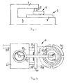
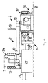
Figure 1 shows a schematic view of a machine-tool 1 intended for the machining of workpieces by means of a tool fitted in the machine. This machine incorporates afirst element 2 in the form of a spindle, and asecond element 3 in the form of a worktable, which are movable relative to one another in a conventional manner in various directions for machining of a workpiece (not depicted) which is intended to be secured to the worktable and be machined by a tool inserted in the spindle. Thefirst element 2 is supported by aspindle head 4 which is itself supported by aframe 5 which also supports thesecond element 3. To test how themachine 1 behaves during mutual displacement of thefirst element 2 and thesecond element 3, atest assembly 6 described below and designed according to the invention is clamped between thefirst element 2 and thesecond element 3. - According to
Figures 2a and2b , thetest assembly 6 incorporates aconventional measuring arm 7 of the "ball bar" type, which has one of its ends linked by anarticulation 8 to abracket 9 intended to be secured in thesecond element 2 of themachine 1, and has its other end linked via anarticulation 10 to abracket 11 intended to be fixed relative to thesecond element 3. Atelescopic element 12 links the twoarticulations articulations arm 7 and its measuring equipment can be connected by anelectrical line 13 to suitable external equipment for recording and analysis of measurement results. - The
test assembly 6 also incorporates apower unit 14 which, like the measuringarm 7, is intended to be fixed between thefirst element 2 and thesecond element 3. For this purpose there is not only abracket 15 for fixing to thefirst element 2 but also abracket 16 for fixing to thesecond element 3. Via abearing 17 thebracket 16 supports a pivotingly mountedarm 18 which has its free end connected to ayoke 19 in whichpiston rods cylinder housing 22 are fastened. Thecylinder housing 22 is provided with working medium via aline 23 and is fixed to theholder 15 which is intended to be pivotable about thefirst element 2 via abearing 24. - The
power unit 14 can be used to apply a force in either direction, parting or drawing together the twobrackets first element 2 and thesecond element 3, when thetest assembly 6 is fitted for use according toFigure 1 . The measuringarm 7 can at the same time be used to ascertain the magnitude of the resulting displacements between theelements - A test assembly according to the invention can be used with basically any kind of mechanical structure. It could be part of a machine tool (as described here) as well as of various kinds of robots or coordinate measuring machines.
-
Figures 3a and 3b show the results of two test series. The results of a first test series are depicted schematically inFigure 3a , in which themachine 1 was programmed to cause thesecond element 3 to perform a circular movement about thefirst element 2 during simultaneous application of force between theelements centre 24 in thefirst element 2, and curves a-f show the magnitude of the deflection in various positions resulting from various amounts of force. In the case of curves b, d and f (provided with arrows) the movement was in a clockwise direction, while that depicted by the other curves a, c and e was in an anticlockwise direction. The force applied was 330N on curves a and b, 660N on curves c and d and 825N on curves e and f. The feed rate was 1000 mm/min in all cases. As can be seen, the amount of displacement increases with the amount of force applied but differently in different directions of movement. -
Figure 3b shows schematically the results of a test series in somewhat different conditions from the test series inFigure 3a . In this case the feed rate was increased to 5000 mm/min. The force applied for curves a-d was the same as inFigure 3a but was increased to 990N for curves e and f. Here again the amount of deflection increases with the amount of force applied and differs in different directions, but not in the same way as inFigure 3a . - The diagrams in
Figures 3a and 3b may be said to constitute the machine's "fingerprint" in various situations and provide, inter alia, information on how its rigidity (or stiffness) varies in different directions at different amounts of load. They also provide a picture of the precision with which the machine can perform a certain type of movement under given conditions. - Another type of test result is depicted in
Figure 4 , where the change in rectilinearity S, measured in µm (micrometers), is shown as a function of the magnitude of the force applied F, indicated in N (newtons). It shows that the change is linear. - It is obvious that further types of tests may provide further types of information about the machine. It is possible, for example, in a specified mutual position between the
first element 2 and thesecond element 3, to carry out measurements both with force increase and with force decrease in order to gain an assessment of hysteresis in the measuring system. This makes it possible to find out how to compensate internal friction and elasticity in the measuring system with a view to immediately produce reliable measuring results. - For precision reasons, the
bearings - The movements described above were in a substantially horizontal plane but there is of course nothing to prevent analysis of movements in a plane with a different orientation, e. g. vertical. An improved version of the conventionally made
articulations power unit 14 with thetelescopic element 12. It is also possible at the same time to make thearticulations - Signal transmission from the measuring
arm 7 is here depicted via anelectrical line 13 but other versions are of course conceivable, e. g. using some kind of wireless transmission (such as Bluetooth or WiFi transmission) to avoid problems with electrical lines during rotary movements. - In the case of the machine tool depicted in
Figure 1 , thefirst element 2 is fixed while thesecond element 3 is movable in a plane perpendicular to the plane of the drawing. There is of course nothing to prevent thesecond element 3 being fixed instead while thefirst element 2 may be movable. A combination of such movements is also possible, depending on what is necessary and desirable in the particular case. - The
power unit 14 described above may within the scope of the invention also take a number of different forms, e. g. it is possible for thearm 18 to take the form of a cylinder housing instead. It is also possible for a single cylinder to be used instead of two, etc. - As previously indicated, the two
brackets power unit 14 to load thefirst element 2 and thesecond element 3, so said brackets have within the scope of the invention to be adapted as appropriate to the particular type of machine. - Diagrams of the type depicted in
Figures 3a, 3b and4 may be used for calculating a large number of different parameters which characterise the machine's behaviour under load. Precision in circular movement can be read off, but precision in linear movements and various types of composite movement can also be calculated. The amount of force dependency provides a good measure of the machine's quality in that little force dependency indicates good quality and good precision, whereas great force dependency indicates less good quality and inferior precision. - In addition, the measured values arising from testing a certain machine tool according to the invention may be used for imposing corrections to rectify deflection in various load situations in the control programme for the machine concerned. The machine's accuracy might thus be substantially improved. The economic gains might become significant if relatively inexpensive machines could therefore be used instead of more expensive high-precision machines. Said measured values obtained may also be used in digital Simulation of the actual machining process to provide a more realistic picture of that process.
-
Figures 5 and 6 each show a schematic representation of a measuringarm 7 of a test assembly, illustrating the working principles of a test assembly of the prior art and of a test assembly according to the invention. - The measuring
arm 7 of the assembly ofFigure 5 is fixed to amachine spindle 2 by means of afirst bracket 9 and afirst articulation 8, and to a machine table 3 by means of asecond bracket 11 and asecond articulation 10. A power unit of the assembly (not shown here) is adapted to apply a static force F between the twoarticulations arm 7 comprises atelescopic element 12, the length change dL(F) of which is then determinable. If themachine spindle 2 performs a movement around thesecond articulation 10 at the machine table 3 that would be a perfect circle when F = 0, the measurement will show that due to stiffness the movement will not be circular when F > 0. Such an assembly is known from the art and described inUS 2002/0189379 Al . -
Figure 6 illustrates the working principle of an exemplary embodiment of an assembly according to the invention. With the assembly ofFigure 6 a dynamic measurement is introduced. The depicted elements of the measuringarm 7 are the same as inFigure 5 . - The power unit (not shown) of the assembly of
Figure 6 is adapted to generate a dynamic, time varying force F(t) between the twoarticulations 8 and 10 (e. g. by means of a piezo actuator). From the perspective of the machine, this can be regarded as a force vector dependent on the relative position between the twoarticulations arm 7 is adapted to measure the varying length vector dL(F(t)) that in the same way will result in varying stiffness in different directions. - The applied force F comprises a static component F0 and a dynamic component F(t). The latter is time variant, e. g. sinusoidal or comprising a step function. The predetermined force can thus be defined as F = F0 + F(t). This means that a dynamic force F(t) is applied in combination with a static force F0 (where the static force can be F0 ≥ 0). Optionally, the dynamic component F(t) is designed so that, when observing the system from outside, it behaves as if it would have a negative damping.
- With the assembly and method according to the invention, it is possible to measure a stiffness in different directions based on the applied force vector of the dynamic force F(t) and deflection vector dL(F). This means that the output comprises the static stiffness (with a constant applied force) as well as the dynamic stiffness (with a time-varying force F(t)) and the damping.
- The static force F0 and the dynamic force can be generated by the same means or separately, e. g. the static force by means of at least one working cylinder of the power unit (as described with respect to
Figures 2a and2b ) and the dynamic force by means of a piezo actuator. - Optionally, the method comprises one or more measurement operations, each of which comprising moving the
machine spindle 9 relative to the machine table 3 in a settable pattern of movement and recording the resulting actual movement path. As described with respect toFigures 3a and 3b , this can be a rotational movement with different forces applied by the test assembly. The predetermined force F applied during each of the one or more measurement operation comprises a dynamically varying portion F(t), so that the applied force varies dynamically during each of the measurement operations. Optionally, as shown inFigures 3a and 3b for a static applied force, also the dynamically varying force can be different for each measurement operation. - Preferably, the measuring part for measuring the deflection vector dL(F) and the force-generation part can be designed to be independent components. This means that if the force-generation part is affected by friction or creates deflections in the device, the measuring part will not be affected by these defects and be able to measure the true deflections on the machine.
- Optionally, the test assembly can be used with a rotating spindle, e. g. fixed to the spindle by means of a special adaptor, as the stiffness in the spindle varies with the rotational speed. In this case, the forces are applied and the measurement is performed during the rotation of the rotating spindle.
- Optionally, the test assembly can also be used for measuring the stiffness in fixtures that are used for holding the workpiece in its place.
- Preferably, the assembly can be battery operated.
- Although the invention is illustrated above, partly with reference to some preferred embodiments, it must be understood that numerous modifications and combinations of different features of the embodiments can be made. All of these modifications lie within the scope of the appended claims.
Claims (15)
- Method for determining machine parameters of a mechanical device (1) in which a first element (2) and a second element (3) are mutually movable in settable patterns of movement, the method comprising• placing a measuring arm (7) between the first and second elements (2, 3),• displacing the first and second elements (2, 3) mutually in a predetermined intended movement path,• applying a predetermined force (F) between the first element (2) and the second element (3) substantially in the longitudinal direction of the measuring arm (7),• recording the resulting actual movement path by means of the measuring arm (7), thereby determining a difference between the intended movement path and the actual movement path, and• deriving, based on the determined difference, machine parameters indicating a condition of the mechanical device (1),characterized in that
the predetermined force (F) comprises a dynamically varying portion (F(t)). - Method according to claim 1,
characterized in that
the dynamically varying portion (F(t)) is time dependent or position dependent, particularly wherein the dynamically varying portion (F(t)) is sinusoidal, subject to an analytic function or subject to a step function. - Method according to claim 1 or claim 2,
characterized by
at least one measurement operation, particularly a plurality of subsequently performed measurement operations, each of which comprising moving the first and second elements (2, 3) mutually in a settable pattern of movement and recording the resulting actual movement path, the predetermined force (F) applied during each measurement operation comprising a dynamically varying portion (F(t)), so that the applied force varies dynamically during each measurement operation, particularly wherein the applied dynamically varying force is different for each measurement operation. - Method according to any one of the preceding claims,
characterized in that
the dynamically varying portion (F(t)) is generated at least partially by means of a piezo actuator, a hydraulic actuator, a pneumatic actuator, an electromagnetic actuator or an electric motor. - Method according to any one of the preceding claims,
characterized in that
the predetermined force (F) comprises a static portion (F0), particularly wherein• the dynamically varying portion (F(t)) and the static portion (F0) are generated by different means; and/or• the predetermined force (F) is defined as
- Method according to any one of the preceding claims,
characterized in that• the predetermined force (F) is applied in various mutual positions between the first and second elements; and/or• recording the resulting actual movement path comprises dynamically determining a current length or a length difference (dL(F)) of the measuring arm (7) while the predetermined force (F) is applied. - Method according to any one of the preceding claims,
characterized in that
the machine parameters comprise at least one of the following:• stiffness, particularly measured in at least two directions based on an applied force vector and on a deflection vector, and particularly comprising a dynamic stiffness value;• displacement in dependence of a direction of movement;• hysteresis;• rectilinearity; and/or• damping. - Method according to any one of the preceding claims,
characterized in that• the mechanical device (1) is a machine tool, wherein the first element (2) is adapted to support a machining tool, and the second element (3) is adapted to support a workpiece, or• the mechanical device (1) is a coordinate measuring machine, wherein the first element (2) is adapted to support a measuring head, and the second element (3) is adapted to support an object to be measured,particularly wherein• the second element (3) is adapted to provide a fixation for holding the workpiece or the object to be measured, respectively, in its place, particularly by means of clamping, and• the machine parameters comprise a stiffness of the fixation. - Method according to any one of the preceding claims,
characterized in that
the mechanical device (1) is a machine tool, and the method comprises a tooling simulation of a specific tooling operation of the machine tool, in the course of which• mutual movements between the first element (2) and the second element (3) are performed that are typical for the tooling operation, and• the dynamically varying portion (F(t)) is applied according to forces typically occurring during the tooling operation. - Assembly (6) for determining machine parameters of a mechanical device (1) in which a first element (2) and a second element (3) are mutually movable, particularly according to the method of any of the preceding claims, the assembly (6) comprising• a measuring arm (7) which has at its ends fastening devices (9, 11) for articulated fixing to the first element (2) and the second element (3) respectively, to make it possible to measure positional change between the first element and the second element, and• a power unit (14) that is arranged to apply a predetermined force substantially parallel with the measuring arm (7) to the first element (2) and the second element (3),characterized in that
the power unit (14) is arranged to apply a predetermined force (F) that comprises at least a dynamically varying portion (F(t)). - Assembly (6) according to claim 10,
characterized in that
the dynamically varying portion (F(t)) is time dependent or position dependent, particularly wherein the dynamically varying portion (F(t)) is sinusoidal, subject to an analytic function or subject to a step function. - Assembly (6) according to claim 10 or claim 11,
characterized in that
the power unit (14) comprises at least one piezo actuator, hydraulic actuator, pneumatic actuator, electromagnetic actuator or electric motor that is adapted to generate the dynamically varying portion (F(t)). - Assembly (6) according to any one of claims 10 to 12,
characterised in that
the power unit (14)• incorporates at least one working cylinder that is adapted to generate a static portion (F0) of the predetermined force (F); and/or• is provided with a first bracket (15) for fixing to the first element (2) and with a second bracket (16) for fixing to the second element (3), wherein the first and second brackets (15, 16) are each provided with a bearing (24, 17) allowing rotation of the power unit (14), particularly wherein the second bracket (16) is provided with devices for fixing one end to the measuring arm (7). - Assembly (6) according to any one of claims 10 to 13,
characterised in that
the first element (2) is a rotating spindle, particularly wherein the assembly (6)• comprises an adaptor for fixing the assembly (6) to the spindle, and• is adapted to measure a stiffness of the spindle, the stiffness varying with a rotational speed of the spindle. - Assembly (6) according to any one of claims 10 to 14,
characterised by
being adapted to be operated cordless and by means of a battery, the assembly (6) particularly comprising a fixedly installed accumulator battery or means for accepting an exchangeable battery.
Priority Applications (3)
| Application Number | Priority Date | Filing Date | Title |
|---|---|---|---|
| EP15155654.5A EP3059548B1 (en) | 2015-02-18 | 2015-02-18 | Method and test assembly for determining machine parameters |
| CN201610080977.8A CN105881099B (en) | 2015-02-18 | 2016-02-04 | Method for determining machine parameter and test suite |
| US15/045,905 US10675725B2 (en) | 2015-02-18 | 2016-02-17 | Method and test assembly for determining machine parameters |
Applications Claiming Priority (1)
| Application Number | Priority Date | Filing Date | Title |
|---|---|---|---|
| EP15155654.5A EP3059548B1 (en) | 2015-02-18 | 2015-02-18 | Method and test assembly for determining machine parameters |
Publications (2)
| Publication Number | Publication Date |
|---|---|
| EP3059548A1 true EP3059548A1 (en) | 2016-08-24 |
| EP3059548B1 EP3059548B1 (en) | 2017-11-22 |
Family
ID=52574046
Family Applications (1)
| Application Number | Title | Priority Date | Filing Date |
|---|---|---|---|
| EP15155654.5A Active EP3059548B1 (en) | 2015-02-18 | 2015-02-18 | Method and test assembly for determining machine parameters |
Country Status (3)
| Country | Link |
|---|---|
| US (1) | US10675725B2 (en) |
| EP (1) | EP3059548B1 (en) |
| CN (1) | CN105881099B (en) |
Cited By (1)
| Publication number | Priority date | Publication date | Assignee | Title |
|---|---|---|---|---|
| WO2020149780A1 (en) | 2019-01-18 | 2020-07-23 | Szipka Karoly | Measurement system, and a method in relation to the measurement system |
Families Citing this family (3)
| Publication number | Priority date | Publication date | Assignee | Title |
|---|---|---|---|---|
| US11782405B2 (en) | 2018-09-03 | 2023-10-10 | Hsd S.P.A. | Operating device for a machine tool |
| CN112496859A (en) * | 2020-12-07 | 2021-03-16 | 中国工程物理研究院机械制造工艺研究所 | Dynamic measurement device and method for comprehensive performance of hydrostatic guide rail |
| JP2022190856A (en) * | 2021-06-15 | 2022-12-27 | 株式会社ディスコ | Measurement tool, operation accuracy measurement system and operation accuracy measurement method |
Citations (3)
| Publication number | Priority date | Publication date | Assignee | Title |
|---|---|---|---|---|
| US5111590A (en) * | 1989-05-23 | 1992-05-12 | Park Joon Ho | Measuring method of machine tool accuracy using a computer aided kinematic transducer link and its apparatus |
| US20020189379A1 (en) | 1999-12-29 | 2002-12-19 | Sven Hjelm | Method and device for testing machine tool |
| GB2377023A (en) * | 2001-06-28 | 2002-12-31 | Daimler Chrysler Ag | Diagnosis of movement precision in a multi-axis system |
Family Cites Families (9)
| Publication number | Priority date | Publication date | Assignee | Title |
|---|---|---|---|---|
| WO1993001646A1 (en) * | 1991-07-12 | 1993-01-21 | Denne Developments Limited | Electromagnetic apparatus for producing linear motion |
| GB9401692D0 (en) * | 1994-01-28 | 1994-03-23 | Renishaw Plc | Performing measurement or calibration on positioning machines |
| US5671541A (en) * | 1995-09-01 | 1997-09-30 | Brown & Sharpe Manufacturing Company | Accuracy verification devices for coordinate measuring machines |
| US6468082B1 (en) * | 1997-09-17 | 2002-10-22 | Advanced Motion Technologies, Llc | Motion-imparting apparatus |
| US7245982B2 (en) | 2002-10-11 | 2007-07-17 | Fidia S.P.A. | System and process for measuring, compensating and testing numerically controlled machine tool heads and/or tables |
| WO2004034164A1 (en) * | 2002-10-11 | 2004-04-22 | Fidia S.P.A. | System and process for measuring, compensating and testing numerically controlled machine tool heads and/or tables |
| CN101813550A (en) * | 2009-11-05 | 2010-08-25 | 吉林大学 | Integrated dynamic testboard of parameter of bogie of railway car |
| CN103158035A (en) * | 2011-12-16 | 2013-06-19 | 贵州大学 | Static extrusion force testing device of shaft parts |
| CN103286633B (en) * | 2013-06-14 | 2015-10-14 | 沈阳飞机工业(集团)有限公司 | Five-coordinate numerally controlled machine tool pivot angle Fast measurement system and error compensating method |
-
2015
- 2015-02-18 EP EP15155654.5A patent/EP3059548B1/en active Active
-
2016
- 2016-02-04 CN CN201610080977.8A patent/CN105881099B/en active Active
- 2016-02-17 US US15/045,905 patent/US10675725B2/en active Active
Patent Citations (3)
| Publication number | Priority date | Publication date | Assignee | Title |
|---|---|---|---|---|
| US5111590A (en) * | 1989-05-23 | 1992-05-12 | Park Joon Ho | Measuring method of machine tool accuracy using a computer aided kinematic transducer link and its apparatus |
| US20020189379A1 (en) | 1999-12-29 | 2002-12-19 | Sven Hjelm | Method and device for testing machine tool |
| GB2377023A (en) * | 2001-06-28 | 2002-12-31 | Daimler Chrysler Ag | Diagnosis of movement precision in a multi-axis system |
Cited By (1)
| Publication number | Priority date | Publication date | Assignee | Title |
|---|---|---|---|---|
| WO2020149780A1 (en) | 2019-01-18 | 2020-07-23 | Szipka Karoly | Measurement system, and a method in relation to the measurement system |
Also Published As
| Publication number | Publication date |
|---|---|
| US10675725B2 (en) | 2020-06-09 |
| US20160236313A1 (en) | 2016-08-18 |
| EP3059548B1 (en) | 2017-11-22 |
| CN105881099A (en) | 2016-08-24 |
| CN105881099B (en) | 2018-10-30 |
Similar Documents
| Publication | Publication Date | Title |
|---|---|---|
| US10675725B2 (en) | Method and test assembly for determining machine parameters | |
| EP2156921B1 (en) | Device for reducing oscillations of a tool spindle | |
| EP2807447A1 (en) | Method for determining a correction value for the monitoring of a fluid bearing and machine having at least one fluid bearing | |
| KR20180116361A (en) | Automatic transformation device and conversion method of thermal displacement correction parameters of a machine tool | |
| JP2021088024A (en) | Numerical control device and control method | |
| US11400597B2 (en) | Methods for the correction of axis motions | |
| JP2019509902A (en) | Calibration apparatus and calibration method | |
| US20220362898A1 (en) | Apparatus for active contact force control in machining and handling operations | |
| CN110695725B (en) | Aviation thin-wall part tool and using method thereof | |
| KR20080088365A (en) | Detection method for a fiducial point of a workpiece on machine and machining apparatus using the same | |
| EP1247064B1 (en) | Method and device for testing machine tool | |
| JP5297749B2 (en) | Automatic dimension measuring device | |
| WO2015014398A1 (en) | Holding apparatus, counterholder arrangement and method for setting a holding apparatus | |
| KR101823052B1 (en) | Method of measuring workpiece for correction of cnc machine job | |
| Røsjordet et al. | Methods for experimentally determining stiffness of a multi-axis machining centre | |
| DE102020212982A1 (en) | Method for reducing measurement errors in a coordinate measuring machine and coordinate measuring machine | |
| Laspas | Closed force loop evaluation of machining systems | |
| Brecher et al. | Static Behavior of Machine Tools | |
| Tonoiu et al. | Equipment and procedure for experimental determination of static rigidity of engine lathes | |
| KNOBLOCH et al. | ERROR MOTION ANALYSIS OF MACHINE SPINDLE UNDER LOAD. | |
| Magoulidou et al. | Comparative study of the static andquasi-static compliance measurementprocedures on machine tools | |
| Kuric et al. | Quality of CNC machine tools and monitoring of their accuracy | |
| Michalski et al. | The impact of support points during the measurement of machine tool bodies on Coordinate Measuring Machines | |
| CN115931223A (en) | High-precision mass center measurement process method for large special-shaped structural part | |
| PL243073B1 (en) | Device for experimental determination of cutting machine tool stiffness |
Legal Events
| Date | Code | Title | Description |
|---|---|---|---|
| PUAI | Public reference made under article 153(3) epc to a published international application that has entered the european phase |
Free format text: ORIGINAL CODE: 0009012 |
|
| AK | Designated contracting states |
Kind code of ref document: A1 Designated state(s): AL AT BE BG CH CY CZ DE DK EE ES FI FR GB GR HR HU IE IS IT LI LT LU LV MC MK MT NL NO PL PT RO RS SE SI SK SM TR |
|
| AX | Request for extension of the european patent |
Extension state: BA ME |
|
| 17P | Request for examination filed |
Effective date: 20170216 |
|
| RBV | Designated contracting states (corrected) |
Designated state(s): AL AT BE BG CH CY CZ DE DK EE ES FI FR GB GR HR HU IE IS IT LI LT LU LV MC MK MT NL NO PL PT RO RS SE SI SK SM TR |
|
| GRAP | Despatch of communication of intention to grant a patent |
Free format text: ORIGINAL CODE: EPIDOSNIGR1 |
|
| RIC1 | Information provided on ipc code assigned before grant |
Ipc: B23Q 17/00 20060101ALI20170703BHEP Ipc: B23Q 17/22 20060101ALI20170703BHEP Ipc: G01B 21/04 20060101AFI20170703BHEP Ipc: G01B 7/14 20060101ALI20170703BHEP |
|
| INTG | Intention to grant announced |
Effective date: 20170718 |
|
| RIN1 | Information on inventor provided before grant (corrected) |
Inventor name: ARCHENTI, ANDREAS Inventor name: PETTERSSON, BO |
|
| GRAS | Grant fee paid |
Free format text: ORIGINAL CODE: EPIDOSNIGR3 |
|
| GRAA | (expected) grant |
Free format text: ORIGINAL CODE: 0009210 |
|
| AK | Designated contracting states |
Kind code of ref document: B1 Designated state(s): AL AT BE BG CH CY CZ DE DK EE ES FI FR GB GR HR HU IE IS IT LI LT LU LV MC MK MT NL NO PL PT RO RS SE SI SK SM TR |
|
| REG | Reference to a national code |
Ref country code: GB Ref legal event code: FG4D |
|
| REG | Reference to a national code |
Ref country code: CH Ref legal event code: EP |
|
| REG | Reference to a national code |
Ref country code: IE Ref legal event code: FG4D |
|
| REG | Reference to a national code |
Ref country code: AT Ref legal event code: REF Ref document number: 948825 Country of ref document: AT Kind code of ref document: T Effective date: 20171215 |
|
| REG | Reference to a national code |
Ref country code: DE Ref legal event code: R096 Ref document number: 602015006091 Country of ref document: DE |
|
| REG | Reference to a national code |
Ref country code: CH Ref legal event code: NV Representative=s name: KAMINSKI HARMANN PATENTANWAELTE AG, LI |
|
| REG | Reference to a national code |
Ref country code: NL Ref legal event code: FP |
|
| REG | Reference to a national code |
Ref country code: FR Ref legal event code: PLFP Year of fee payment: 4 |
|
| REG | Reference to a national code |
Ref country code: SE Ref legal event code: TRGR |
|
| REG | Reference to a national code |
Ref country code: LT Ref legal event code: MG4D |
|
| REG | Reference to a national code |
Ref country code: AT Ref legal event code: MK05 Ref document number: 948825 Country of ref document: AT Kind code of ref document: T Effective date: 20171122 |
|
| PG25 | Lapsed in a contracting state [announced via postgrant information from national office to epo] |
Ref country code: NO Free format text: LAPSE BECAUSE OF FAILURE TO SUBMIT A TRANSLATION OF THE DESCRIPTION OR TO PAY THE FEE WITHIN THE PRESCRIBED TIME-LIMIT Effective date: 20180222 Ref country code: ES Free format text: LAPSE BECAUSE OF FAILURE TO SUBMIT A TRANSLATION OF THE DESCRIPTION OR TO PAY THE FEE WITHIN THE PRESCRIBED TIME-LIMIT Effective date: 20171122 Ref country code: LT Free format text: LAPSE BECAUSE OF FAILURE TO SUBMIT A TRANSLATION OF THE DESCRIPTION OR TO PAY THE FEE WITHIN THE PRESCRIBED TIME-LIMIT Effective date: 20171122 Ref country code: FI Free format text: LAPSE BECAUSE OF FAILURE TO SUBMIT A TRANSLATION OF THE DESCRIPTION OR TO PAY THE FEE WITHIN THE PRESCRIBED TIME-LIMIT Effective date: 20171122 |
|
| PG25 | Lapsed in a contracting state [announced via postgrant information from national office to epo] |
Ref country code: RS Free format text: LAPSE BECAUSE OF FAILURE TO SUBMIT A TRANSLATION OF THE DESCRIPTION OR TO PAY THE FEE WITHIN THE PRESCRIBED TIME-LIMIT Effective date: 20171122 Ref country code: AT Free format text: LAPSE BECAUSE OF FAILURE TO SUBMIT A TRANSLATION OF THE DESCRIPTION OR TO PAY THE FEE WITHIN THE PRESCRIBED TIME-LIMIT Effective date: 20171122 Ref country code: HR Free format text: LAPSE BECAUSE OF FAILURE TO SUBMIT A TRANSLATION OF THE DESCRIPTION OR TO PAY THE FEE WITHIN THE PRESCRIBED TIME-LIMIT Effective date: 20171122 Ref country code: BG Free format text: LAPSE BECAUSE OF FAILURE TO SUBMIT A TRANSLATION OF THE DESCRIPTION OR TO PAY THE FEE WITHIN THE PRESCRIBED TIME-LIMIT Effective date: 20180222 Ref country code: LV Free format text: LAPSE BECAUSE OF FAILURE TO SUBMIT A TRANSLATION OF THE DESCRIPTION OR TO PAY THE FEE WITHIN THE PRESCRIBED TIME-LIMIT Effective date: 20171122 Ref country code: GR Free format text: LAPSE BECAUSE OF FAILURE TO SUBMIT A TRANSLATION OF THE DESCRIPTION OR TO PAY THE FEE WITHIN THE PRESCRIBED TIME-LIMIT Effective date: 20180223 |
|
| PG25 | Lapsed in a contracting state [announced via postgrant information from national office to epo] |
Ref country code: SK Free format text: LAPSE BECAUSE OF FAILURE TO SUBMIT A TRANSLATION OF THE DESCRIPTION OR TO PAY THE FEE WITHIN THE PRESCRIBED TIME-LIMIT Effective date: 20171122 Ref country code: CZ Free format text: LAPSE BECAUSE OF FAILURE TO SUBMIT A TRANSLATION OF THE DESCRIPTION OR TO PAY THE FEE WITHIN THE PRESCRIBED TIME-LIMIT Effective date: 20171122 Ref country code: DK Free format text: LAPSE BECAUSE OF FAILURE TO SUBMIT A TRANSLATION OF THE DESCRIPTION OR TO PAY THE FEE WITHIN THE PRESCRIBED TIME-LIMIT Effective date: 20171122 Ref country code: CY Free format text: LAPSE BECAUSE OF FAILURE TO SUBMIT A TRANSLATION OF THE DESCRIPTION OR TO PAY THE FEE WITHIN THE PRESCRIBED TIME-LIMIT Effective date: 20171122 Ref country code: EE Free format text: LAPSE BECAUSE OF FAILURE TO SUBMIT A TRANSLATION OF THE DESCRIPTION OR TO PAY THE FEE WITHIN THE PRESCRIBED TIME-LIMIT Effective date: 20171122 |
|
| REG | Reference to a national code |
Ref country code: DE Ref legal event code: R097 Ref document number: 602015006091 Country of ref document: DE |
|
| PG25 | Lapsed in a contracting state [announced via postgrant information from national office to epo] |
Ref country code: PL Free format text: LAPSE BECAUSE OF FAILURE TO SUBMIT A TRANSLATION OF THE DESCRIPTION OR TO PAY THE FEE WITHIN THE PRESCRIBED TIME-LIMIT Effective date: 20171122 Ref country code: RO Free format text: LAPSE BECAUSE OF FAILURE TO SUBMIT A TRANSLATION OF THE DESCRIPTION OR TO PAY THE FEE WITHIN THE PRESCRIBED TIME-LIMIT Effective date: 20171122 Ref country code: SM Free format text: LAPSE BECAUSE OF FAILURE TO SUBMIT A TRANSLATION OF THE DESCRIPTION OR TO PAY THE FEE WITHIN THE PRESCRIBED TIME-LIMIT Effective date: 20171122 Ref country code: IT Free format text: LAPSE BECAUSE OF FAILURE TO SUBMIT A TRANSLATION OF THE DESCRIPTION OR TO PAY THE FEE WITHIN THE PRESCRIBED TIME-LIMIT Effective date: 20171122 |
|
| PG25 | Lapsed in a contracting state [announced via postgrant information from national office to epo] |
Ref country code: MC Free format text: LAPSE BECAUSE OF FAILURE TO SUBMIT A TRANSLATION OF THE DESCRIPTION OR TO PAY THE FEE WITHIN THE PRESCRIBED TIME-LIMIT Effective date: 20171122 |
|
| PLBE | No opposition filed within time limit |
Free format text: ORIGINAL CODE: 0009261 |
|
| STAA | Information on the status of an ep patent application or granted ep patent |
Free format text: STATUS: NO OPPOSITION FILED WITHIN TIME LIMIT |
|
| 26N | No opposition filed |
Effective date: 20180823 |
|
| REG | Reference to a national code |
Ref country code: IE Ref legal event code: MM4A |
|
| REG | Reference to a national code |
Ref country code: BE Ref legal event code: MM Effective date: 20180228 |
|
| PG25 | Lapsed in a contracting state [announced via postgrant information from national office to epo] |
Ref country code: SI Free format text: LAPSE BECAUSE OF FAILURE TO SUBMIT A TRANSLATION OF THE DESCRIPTION OR TO PAY THE FEE WITHIN THE PRESCRIBED TIME-LIMIT Effective date: 20171122 Ref country code: LU Free format text: LAPSE BECAUSE OF NON-PAYMENT OF DUE FEES Effective date: 20180218 |
|
| PG25 | Lapsed in a contracting state [announced via postgrant information from national office to epo] |
Ref country code: IE Free format text: LAPSE BECAUSE OF NON-PAYMENT OF DUE FEES Effective date: 20180218 |
|
| PG25 | Lapsed in a contracting state [announced via postgrant information from national office to epo] |
Ref country code: BE Free format text: LAPSE BECAUSE OF NON-PAYMENT OF DUE FEES Effective date: 20180228 |
|
| PG25 | Lapsed in a contracting state [announced via postgrant information from national office to epo] |
Ref country code: MT Free format text: LAPSE BECAUSE OF NON-PAYMENT OF DUE FEES Effective date: 20180218 |
|
| PG25 | Lapsed in a contracting state [announced via postgrant information from national office to epo] |
Ref country code: TR Free format text: LAPSE BECAUSE OF FAILURE TO SUBMIT A TRANSLATION OF THE DESCRIPTION OR TO PAY THE FEE WITHIN THE PRESCRIBED TIME-LIMIT Effective date: 20171122 |
|
| PGFP | Annual fee paid to national office [announced via postgrant information from national office to epo] |
Ref country code: NL Payment date: 20200219 Year of fee payment: 6 Ref country code: SE Payment date: 20200220 Year of fee payment: 6 |
|
| PG25 | Lapsed in a contracting state [announced via postgrant information from national office to epo] |
Ref country code: PT Free format text: LAPSE BECAUSE OF FAILURE TO SUBMIT A TRANSLATION OF THE DESCRIPTION OR TO PAY THE FEE WITHIN THE PRESCRIBED TIME-LIMIT Effective date: 20171122 |
|
| PGFP | Annual fee paid to national office [announced via postgrant information from national office to epo] |
Ref country code: CH Payment date: 20200219 Year of fee payment: 6 |
|
| PG25 | Lapsed in a contracting state [announced via postgrant information from national office to epo] |
Ref country code: MK Free format text: LAPSE BECAUSE OF NON-PAYMENT OF DUE FEES Effective date: 20171122 Ref country code: HU Free format text: LAPSE BECAUSE OF FAILURE TO SUBMIT A TRANSLATION OF THE DESCRIPTION OR TO PAY THE FEE WITHIN THE PRESCRIBED TIME-LIMIT; INVALID AB INITIO Effective date: 20150218 |
|
| PG25 | Lapsed in a contracting state [announced via postgrant information from national office to epo] |
Ref country code: IS Free format text: LAPSE BECAUSE OF FAILURE TO SUBMIT A TRANSLATION OF THE DESCRIPTION OR TO PAY THE FEE WITHIN THE PRESCRIBED TIME-LIMIT Effective date: 20180322 Ref country code: AL Free format text: LAPSE BECAUSE OF FAILURE TO SUBMIT A TRANSLATION OF THE DESCRIPTION OR TO PAY THE FEE WITHIN THE PRESCRIBED TIME-LIMIT Effective date: 20171122 |
|
| REG | Reference to a national code |
Ref country code: SE Ref legal event code: EUG |
|
| PG25 | Lapsed in a contracting state [announced via postgrant information from national office to epo] |
Ref country code: LI Free format text: LAPSE BECAUSE OF NON-PAYMENT OF DUE FEES Effective date: 20210228 Ref country code: CH Free format text: LAPSE BECAUSE OF NON-PAYMENT OF DUE FEES Effective date: 20210228 |
|
| PG25 | Lapsed in a contracting state [announced via postgrant information from national office to epo] |
Ref country code: SE Free format text: LAPSE BECAUSE OF NON-PAYMENT OF DUE FEES Effective date: 20210219 |
|
| REG | Reference to a national code |
Ref country code: NL Ref legal event code: MM Effective date: 20210301 |
|
| PG25 | Lapsed in a contracting state [announced via postgrant information from national office to epo] |
Ref country code: NL Free format text: LAPSE BECAUSE OF NON-PAYMENT OF DUE FEES Effective date: 20210301 |
|
| PGFP | Annual fee paid to national office [announced via postgrant information from national office to epo] |
Ref country code: FR Payment date: 20230221 Year of fee payment: 9 |
|
| PGFP | Annual fee paid to national office [announced via postgrant information from national office to epo] |
Ref country code: GB Payment date: 20230221 Year of fee payment: 9 Ref country code: DE Payment date: 20220620 Year of fee payment: 9 |