EP3082193A1 - Difference phase slider assembly - Google Patents
Difference phase slider assembly Download PDFInfo
- Publication number
- EP3082193A1 EP3082193A1 EP16164465.3A EP16164465A EP3082193A1 EP 3082193 A1 EP3082193 A1 EP 3082193A1 EP 16164465 A EP16164465 A EP 16164465A EP 3082193 A1 EP3082193 A1 EP 3082193A1
- Authority
- EP
- European Patent Office
- Prior art keywords
- coupling device
- feed
- phase shifter
- shifter assembly
- central
- Prior art date
- Legal status (The legal status is an assumption and is not a legal conclusion. Google has not performed a legal analysis and makes no representation as to the accuracy of the status listed.)
- Granted
Links
Images


Classifications
-
- H—ELECTRICITY
- H01—ELECTRIC ELEMENTS
- H01P—WAVEGUIDES; RESONATORS, LINES, OR OTHER DEVICES OF THE WAVEGUIDE TYPE
- H01P1/00—Auxiliary devices
- H01P1/18—Phase-shifters
- H01P1/184—Strip line phase-shifters
-
- H—ELECTRICITY
- H01—ELECTRIC ELEMENTS
- H01P—WAVEGUIDES; RESONATORS, LINES, OR OTHER DEVICES OF THE WAVEGUIDE TYPE
- H01P1/00—Auxiliary devices
- H01P1/06—Movable joints, e.g. rotating joints
- H01P1/062—Movable joints, e.g. rotating joints the relative movement being a rotation
- H01P1/063—Movable joints, e.g. rotating joints the relative movement being a rotation with a limited angle of rotation
- H01P1/064—Movable joints, e.g. rotating joints the relative movement being a rotation with a limited angle of rotation the axis of rotation being perpendicular to the transmission path, e.g. hinge joint
-
- H—ELECTRICITY
- H01—ELECTRIC ELEMENTS
- H01P—WAVEGUIDES; RESONATORS, LINES, OR OTHER DEVICES OF THE WAVEGUIDE TYPE
- H01P1/00—Auxiliary devices
- H01P1/18—Phase-shifters
- H01P1/182—Waveguide phase-shifters
-
- H—ELECTRICITY
- H01—ELECTRIC ELEMENTS
- H01P—WAVEGUIDES; RESONATORS, LINES, OR OTHER DEVICES OF THE WAVEGUIDE TYPE
- H01P5/00—Coupling devices of the waveguide type
- H01P5/02—Coupling devices of the waveguide type with invariable factor of coupling
- H01P5/022—Transitions between lines of the same kind and shape, but with different dimensions
- H01P5/028—Transitions between lines of the same kind and shape, but with different dimensions between strip lines
-
- H—ELECTRICITY
- H01—ELECTRIC ELEMENTS
- H01P—WAVEGUIDES; RESONATORS, LINES, OR OTHER DEVICES OF THE WAVEGUIDE TYPE
- H01P5/00—Coupling devices of the waveguide type
- H01P5/12—Coupling devices having more than two ports
-
- H—ELECTRICITY
- H01—ELECTRIC ELEMENTS
- H01Q—ANTENNAS, i.e. RADIO AERIALS
- H01Q3/00—Arrangements for changing or varying the orientation or the shape of the directional pattern of the waves radiated from an antenna or antenna system
- H01Q3/26—Arrangements for changing or varying the orientation or the shape of the directional pattern of the waves radiated from an antenna or antenna system varying the relative phase or relative amplitude of energisation between two or more active radiating elements; varying the distribution of energy across a radiating aperture
- H01Q3/30—Arrangements for changing or varying the orientation or the shape of the directional pattern of the waves radiated from an antenna or antenna system varying the relative phase or relative amplitude of energisation between two or more active radiating elements; varying the distribution of energy across a radiating aperture varying the relative phase between the radiating elements of an array
- H01Q3/32—Arrangements for changing or varying the orientation or the shape of the directional pattern of the waves radiated from an antenna or antenna system varying the relative phase or relative amplitude of energisation between two or more active radiating elements; varying the distribution of energy across a radiating aperture varying the relative phase between the radiating elements of an array by mechanical means
Definitions
- the invention relates to a differential phase shifter assembly according to the preamble of claim 1.
- the mobile radio antennas provided for a base station usually comprise an antenna arrangement with a reflector, in front of which, in the vertical direction offset from one another, a multiplicity of radiator elements are provided and thus form an array. These can radiate and receive, for example, in one or two mutually perpendicular polarizations.
- the radiator elements can be designed to receive only in a frequency band.
- the antenna arrangement can also be designed as a multi-band antenna, for example for transmitting and receiving two mutually offset frequency bands. Also so-called. Triband antennas are basically known.
- the mobile radio network is designed in the form of a cell, wherein each cell is assigned a corresponding base station with at least one mobile radio antenna for transmission and reception.
- the antennas are designed so that they usually radiate at a certain angle relative to the horizontal with the main lobe down, whereby a certain cell size is determined. This lowering angle is also known as the downtilt angle.
- a generic difference phase shifter assembly is already out of the EP 1 208 614 B1 have become known in which in a single-column antenna array with a plurality of superimposed radiators, the downtilt angle is continuously adjustable differently.
- differential phase shifters are used which, with different settings, cause the propagation time and thus the phase shift at the two outputs of a respective phase shifter to be adjusted in different directions, as a result of which the lowering angle can be set.
- phase shift angle can be carried out manually or by means of a remotely controllable retrofit unit, as for example according to the DE 101 04 564 C1 is known.
- the generic differential phase shifter assembly includes at least two concentrically arranged stripline sections. At the opposite ends of these stripline sections are joints provided on which to different emitters of an antenna array (in particular a mobile radio antenna) extending connecting lines can be connected.
- an antenna array in particular a mobile radio antenna
- the phase shifter assembly further comprises a supply and / or Abgriffseinrichung (which is also referred to below as feed and / or Abgriffsarm or - element), which is pivotable about a central and / or Verschwenkachse, wherein the pointer-shaped feed element over the is pivotable across several concentric strip lines.
- a supply and / or Abgriffseinrichung which is also referred to below as feed and / or Abgriffsarm or - element
- feed and / or Abgriffsarm or - element which is pivotable about a central and / or Verschwenkachse, wherein the pointer-shaped feed element over the is pivotable across several concentric strip lines.
- the pointer-shaped feed and / or tap arm is capacitively coupled to the strip lines, with the interposition of a generally fixed dielectric.
- the pointer-shaped feed element is fed capacitively via a central feed line, for which purpose the central feed line (which is connected to an antenna network) has a feed line-side connected first coupling surface in the region of the central or pivot axis. Staggered in the direction of the central or pivot axis is the interposition of a dielectric or insulator belonging to the supply and / or Abgriffsarm or galvanically connected second coupling surface provided.
- the entire described functional structure is housed in two half-shell-shaped housing parts, which cause the electrical shielding of the differential phase shifter assembly thus formed.
- the individual phases with respect to the received and / or transmitted signals for example a mobile radio antenna can be adjusted very efficiently and effectively, whereby, for example, different Absenkwinkel (down-tilt angle) are adjustable, as for example in the EP 1 208 614 B1 is comprehensively described.
- a galvanically connected to the feed line first feeder line side coupling device is provided which comprises parallel to the central axis of the central feed line offset dish-shaped coupling device sections.
- a second tap arm side coupling device is also arranged in disc form, which is connected to the arm or pointer-shaped feed and / or tapping element.
- the invention provides with surprisingly simple means a further improved differential phase shifter assembly.
- the phase shifter assembly comprises an increasingly larger number of concentrically arranged strip lines
- the remaining space in the region of the central and / or pivot axis for the pointer-shaped feed element is comparatively small.
- the explained capacitive feed that is, the capacitive coupling between the first feed line side coupling surface and the pointer element side second coupling surface must be accommodated.
- a leading wave always also has a reflecting wave which leads to a certain standing wave ratio, which is also referred to briefly as VSWR (standing wave ratio).
- VSWR standing wave ratio
- a spaced apart and galvanically separate additional coupling device or disk is positioned above the actual pointer head of the pointer-shaped feed element, which is penetrated by the central or pivot axis. This is preferably separated from the electrically conductive pointer head by means of a disc-shaped interposed insulator.
- a plastic film on at least one or on both surfaces facing each other of the pointer head or the adjacent surface of the coupling disc may be sufficient.
- FIG. 1 is a schematic plan view of a representation of the phase shifter assembly according to the invention reproduced with removed housing cover or removed housing half.
- the differential phase shifter assembly comprises three part-circular strip lines 5, which are arranged concentrically to a center 7.
- the strip lines 5 are usually arranged in a common plane E.
- the strip lines need not necessarily be semi-circular but may also have a pitch of more than 180 °.
- the strip lines 5 have a length with which they enclose only a partial angle of less than 180 °.
- the aforementioned feeding and / or tapping device 13 comprises in the illustrated embodiment, a pointer or arm-shaped feed or tapping element 13a, which is also referred to below as a feed and / or Abgriffsarm 13a.
- This feed and / or tapping element 13a is of the internal Central and / or pivot axis 9 arranged over the strip lines 5 away extending to the outermost strip line and covers each with a coupling section 15 an underlying strip line coupling section 5 '( FIG. 3 ) of the respective strip line 5, wherein the coupling portion 15 of the pointer or Abgriffsarms 13 is arranged rotatable at a distance above the respective strip line 5 of time.
- the respective path length between a stripline coupling section 5 'of a stripline 5 and the respective remaining stripline end 17 is increased and reduced in relation to the opposite stripline section, whereby in opposite directions the duration of the signals is changed in a known manner.
- a down-tilt angle of connected radiators can be set differently. For this purpose, only indicated and leading to the individual radiators 1a to 1f connecting lines 2 are connected to the stripline ends 17 at 19 formed there connection points in the drawings.
- FIG. 2 Based on FIG. 2 an enlarged detail of the feeding and / or tapping device is shown, with the aforementioned feed and / or Abgriffsarm, which can be adjusted to a central axis 7 on the strip lines 5 away, usually to the stripline end 17.
- four concentric strip lines 5 are provided in the embodiments explained below, in accordance with the plan view FIG. 2 are shown only in part, with reference to FIG. 3 a cross-sectional view along the line III-III in FIG. 2 is reproduced. It is in FIG. 3 in section, the housing 18 with the two housing halves 18a and 18b visible.
- a central feed 20 with a first coupling device or coupling surface 21 is provided, which is connected via a coupling connection 22 with a central feed line 23 ( FIG. 3 ).
- first coupling surface 21 (hereinafter also referred to as the feed line side coupling surface or coupling device 21) is offset in the direction of the central or pivot axis 9 lying a pointer head 25 of the feed and / or Abgriffsarmes 13, usually with the interposition of a dielectric or Isolator 27.
- the feed line-side coupling surface 21 is preferably designed as a coupling ring 21 '( FIG. 4 ).
- the pointer or Abgriffsarm-side second coupling device or coupling surface 24 forming the pointer head 25 generally has a central recess 29, through which a pivot axis forming and the pointer or Abgriffsarm 13 supporting axle 31 is provided, which is formed while avoiding a galvanic connection of an isolator effect generating plastic ,
- the entire assembly is also usually held by a base forming insulator 33 on the inside of the housing 1 ', that is, the at least one housing half 1 mechanically and anchored.
- the axle body 31 passes through the entire feed device 20, including a bore 22c in the lower part of the housing 18, that is to say the lower housing half or shell 18b in the exemplary embodiment shown, the axle body 31 being provided with an axle body head 31a has a larger outer diameter and rests on the outside of said housing half 18b in the final assembled state, in this case so also the mentioned insulator 33 in a correspondingly formed therein bore 22a including a corresponding bore 21a in the coupling surface 21 (and the others explained below here located parts) interspersed.
- axle body has a larger outer diameter than the Achsismekopf, which can be inserted with its smaller diameter in a corresponding bore 22c in the associated housing half, until the axle body with a larger diameter at its corresponding step approach, for example on the inside of the associated housing shell rests.
- an additional coupling device 35 is provided parallel to the pointer head 25, preferably in the form of a coupling disk 35 '. This is along the central and / or pivot axis 9 offset lying to the adjacent surface of the pointer head 25 is provided to effect an additional capacitive coupling between the pointer head 25 and the coupling device 35.
- At least one insulation 39 is provided, e.g. in the form of an insulator film 39 'or in the form of an insulator film 39' is provided.
- This separating film effecting a galvanic separation can also be produced, for example, by a glued-on plastic film or by an applied plastic paint.
- the aforementioned insulation 39 and the coupling device 35 have in the illustrated embodiment, a recess or bore 39a and 35a, which is penetrated by the axle 31 (which incidentally also by a corresponding bore 22a in the illustrated embodiment, the second housing half or shell 18a permeated and held against it against axial tilting and secured).
- the aforementioned coupling device 35 can be realized, for example, in the form of the aforementioned coupling disk 35 ', which can have different sizes, for example different sizes also to the pointer head 25 located underneath.
- the coupling device 35 can be in the longitudinal and / or transverse direction, however also have in terms of the resulting in plan view réelleachir different sizes and shapes.
- the preferably disk-shaped coupling device 35 can also be implemented with different material thicknesses (i.e., with different thicknesses and heights) as required and required.
- the coupling device 35 may be realized, for example, from a plurality of letters, which are arranged one above the other or which consist of different disc parts in the circumferential direction or are composed. There are no restrictions in this regard.
- the invention also makes it possible that with comparatively small available central space in the region of the central and pivot axis, that is in the region between the central and pivot axis 9 and the closest and thus immediately adjacent innermost strip line 5, the dimensions of Pointer head 25 can be reduced even in the radial direction to the pivot axis 9, whereby the pivoting range to the left and right can even be increased.
- the mentioned additional further coupling device 35 is preferably arranged correspondingly in the form of the mentioned coupling disc 35 '.
- the additional metal-made (ie generally electrically conductive) or at least provided with a metallic outer layer coupling device 35 preferably in the form of the coupling disc 35 'so the standing wave ratio (VSWR) of the entire phase shifter is affected. This not only results in an overall improvement of the standing wave ratio but also opens up the possibility that an optimization and / or adjustment possibility exists with regard to the standing wave ratio (VSWR).
- the feeding and / or tapping device 13 as a feed and / or Abgriffsarm pair 13 'is formed.
- the design of the feed and / or tapping device 13 is such that the pointer-shaped feed or tapping device 13 is quasi fork-shaped, starting from the central or pivot axis 9, so that a first feed and / or tap arm 13a on one side extends over all strip lines 5 away to its radially outer end and a second feed and / or Abgriffsarm 13 b is guided on the opposite side over all strip lines 5 away to an outer end.
- each of the two supply or Abgriffsarme 13a, 13b, which form the supply or Abgriffsarm pair 13 ', with a common or galvanically isolated second coupling means 24a, 24b are provided, wherein the one coupling means 24a with the first feed - And / or Abgriffsarm 13 a and the further coupling device 24 b (which also to the second Coupling heard) is electrically connected to the other supply and / or Abgriffsarm 13b.
- the aforementioned two second coupling devices 24a, 24b thus each represent a pointer head 25a, 25b for the two feed and / or tapping elements 13a, 13b.
- the two feed and / or tap arm-side coupling devices 24a, 24b forming a pair can be in galvanic contact with each other or capacitively coupled to one another, with the interposition of an insulator 45 or a thin insulator layer 45, film layer 45etc.
- the basic structure does not change to the previous embodiments.
- the two feeding and / or Abgriffsarm-side coupling means 24a, 24b may be arranged on the two opposite sides of the first or feed line side coupling device 21. Die Kopeckung °. In other words, then one of the two supply and / or Abgriffsarme 13a with its associated coupling device 24b between the first feiseineitungs patenten coupling device 21 and a fixed housing usually provided and a galvanic isolation to the housing 18, 18b causing insulating base (insulator 33) arranged.
- an insulator or an insulating layer 27a etc. is provided between the second coupling device 24a, for example in the form of the pointer head 25a and the adjacent and parallel thereto extending first or feed line side coupling device 21, to allow the capacitive coupling while avoiding a galvanic contact.
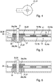
- FIG. 7 is in addition to the embodiment according to FIG. 6 shown that in this case also as a further or third coupling means 35 not only described on the basis of the previous embodiments and in FIG. 7 Also provided with the reference numeral 35a coupling device 35, for example in the form of the coupling disc 35 'but the second additional coupling device 35b is provided.
- the structure is such that on both sides adjacent to the first or supply line side coupling device 21 each have a second or dining and / or Abgriffsarm-side coupling device 24a or 24b is arranged, in addition to the lying further out following each one according to the invention provided coupling device 35a and 35b is positioned.
- FIG. 7 Alternating to the variant according to FIG. 7 would also be possible that, for example, only in FIG. 7 below provided according to the invention provided coupling device 35, for example in the form of the coupling disc 35b, so that inversely to the in FIG. 7 shown overhead further coupling device 35, for example in the form of the local coupling disk 35a can be dispensed with. It is then an embodiment more or less identical to that after FIG. 3 , only in 180 ° twisted orientation. Functionally, this results in no difference.
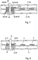
- FIG. 8 differs from the exemplary embodiment according to FIG. 3 differs in that the inventively provided third or further coupling device 35 is not adjacent to the second coupling device 24a of a feed and / or Abgiffs worn 13 but on the opposite side of the first or feeder line side coupling device 21 of the first or feed side coupling device 21 is arranged.
- the advantages of the invention can be realized.
Abstract
Eine verbesserte Differenz-Phasenschieberbaugruppe zeichnet sich unter anderem durch die folgenden Merkmale aus: - es ist zumindest eine weitere kapazitive Koppeleinrichtung (35) im Bereich der Zentral- und/oder Schwenkachse (9) vorgesehen, und - die zumindest eine weitere Koppeleinrichtung (35; 35a, 35b) a) ist neben der zweiten Koppeleinrichtung (24) so angeordnet, dass die zweite Koppeleinrichtung (24) zwischen der ersten Koppeleinrichtung (21) und der zumindest einen weiteren kapazitiven Koppeleinrichtung (35) positioniert ist, und/oder b) ist benachbart zur ersten Koppeleinrichtung (21) so angeordnet, dass die erste Koppeleinrichtung (21) zwischen der zweiten Koppeleinrichtung (24) und der zumindest einen weiteren kapazitiven Koppeleinrichtung (35) positioniert ist. An improved differential phase shifter assembly is characterized, inter alia, by the following features: - There is provided at least one further capacitive coupling device (35) in the region of the central and / or pivot axis (9), and the at least one further coupling device (35; 35a, 35b) a) is arranged next to the second coupling device (24) so that the second coupling device (24) between the first coupling device (21) and the at least one further capacitive coupling device (35) is positioned, and / or b) is arranged adjacent to the first coupling device (21) so that the first coupling device (21) is positioned between the second coupling device (24) and the at least one further capacitive coupling device (35).
Description
Die Erfindung betrifft eine Differenz-Phasenschieberbaugruppe nach dem Oberbegriff des Anspruches 1.The invention relates to a differential phase shifter assembly according to the preamble of claim 1.
Insbesondere die für eine Basisstation vorgesehenen Mobilfunkantennen umfassen üblicherweise eine Antennenanordnung mit einem Reflektor, vor welchem in Vertikalrichtung versetzt zueinander liegend eine Vielzahl von Strahlerelementen vorgesehen ist und somit ein Array bilden. Diese können beispielsweise in einer oder zwei senkrecht zueinander stehenden Polarisationen strahlen und empfangen. Die Strahlerelemente können dabei zum Empfang lediglich in einem Frequenzband ausgebildet sein. Die Antennenanordnung kann aber auch als Multiband-Antenne ausgebildet sein, beispielsweise zum Senden und Empfangen von zwei versetzt zueinander liegenden Frequenzbändern. Auch sog. Triband-Antennen sind grundsätzlich bekannt.In particular, the mobile radio antennas provided for a base station usually comprise an antenna arrangement with a reflector, in front of which, in the vertical direction offset from one another, a multiplicity of radiator elements are provided and thus form an array. These can radiate and receive, for example, in one or two mutually perpendicular polarizations. The radiator elements can be designed to receive only in a frequency band. However, the antenna arrangement can also be designed as a multi-band antenna, for example for transmitting and receiving two mutually offset frequency bands. Also so-called. Triband antennas are basically known.
Bekanntermaßen ist das Mobilfunknetz zellenförmig gestaltet, wobei jeder Zelle eine entsprechende Basisstation mit zumindest einer Mobilfunkantenne zum Senden und Empfangen zugeordnet ist. Die Antennen sind dabei so aufgebaut, dass sie in der Regel in einem bestimmten Winkel gegenüber der Horizontalen mit nach unten gerichteter Hauptkeule strahlen, wodurch eine bestimmte Zellengröße festgelegt wird. Dieser Absenkwinkel wird bekanntermaßen auch als Downtilt-Winkel bezeichnet.As is known, the mobile radio network is designed in the form of a cell, wherein each cell is assigned a corresponding base station with at least one mobile radio antenna for transmission and reception. The antennas are designed so that they usually radiate at a certain angle relative to the horizontal with the main lobe down, whereby a certain cell size is determined. This lowering angle is also known as the downtilt angle.
Eine gattungsbildende Differenz-Phasenschieberbaugruppe ist bereits aus der
Dabei kann die Ein- und Verstellung des Phasenschieberwinkels manuell oder mittels einer fernsteuerbaren Nachrüst-Einheit durchgeführt werden, wie dies beispielsweise gemäß der
Die gattungsbildende Differenz-Phasenschieberbaugruppe umfasst zumindest zwei konzentrisch angeordnete Streifenleitungsabschnitte. An den jeweils gegenüberliegenden Enden dieser Streifenleitungsabschnitte sind Verbindungsstellen vorgesehen, an denen zu verschiedenen Strahlern eines Antennenarrays (insbesondere einer Mobilfunkantenne) verlaufende Verbindungsleitungen angeschlossen werden können.The generic differential phase shifter assembly includes at least two concentrically arranged stripline sections. At the opposite ends of these stripline sections are joints provided on which to different emitters of an antenna array (in particular a mobile radio antenna) extending connecting lines can be connected.
Die Phasenschieberbaugruppe weist ferner eine Speise- und/oder Abgriffseinrichung auf (welche nachfolgend teilweise auch als Speise- und/oder Abgriffsarm oder - element bezeichnet wird), welches um eine Zentral- und/oder Verschwenkachse verschwenkbar ist, wobei das zeigerförmige Speiseelement dabei über die mehreren konzentrischen Streifenleitungen hinweg verschwenkbar ist.The phase shifter assembly further comprises a supply and / or Abgriffseinrichung (which is also referred to below as feed and / or Abgriffsarm or - element), which is pivotable about a central and / or Verschwenkachse, wherein the pointer-shaped feed element over the is pivotable across several concentric strip lines.
Der zeigerförmige Speise- und/oder Abgriffsarm ist dabei kapazitiv mit den Streifenleitungen gekoppelt, und zwar unter Zwischenschaltung eines in der Regel festen Dielektrikums.The pointer-shaped feed and / or tap arm is capacitively coupled to the strip lines, with the interposition of a generally fixed dielectric.
Über eine zentrale Speiseleitung wird das zeigerförmige Speiseelement kapazitiv gespeist, wozu die zentrale Speiseleitung (die mit einem Antennennetzwerk verbunden ist) eine speiseleitungsseitige angebundene erste Koppelfläche im Bereich der Zentral- oder Schwenkachse aufweist. In Richtung der Zentral- oder Verschwenkachse versetzt liegend ist unter Zwischenschaltung eines Dielektrikums oder Isolators die zu dem Speise- und/oder Abgriffsarm gehörende oder damit galvanisch verbundene zweite Koppelfläche vorgesehen.The pointer-shaped feed element is fed capacitively via a central feed line, for which purpose the central feed line (which is connected to an antenna network) has a feed line-side connected first coupling surface in the region of the central or pivot axis. Staggered in the direction of the central or pivot axis is the interposition of a dielectric or insulator belonging to the supply and / or Abgriffsarm or galvanically connected second coupling surface provided.
Der gesamte erläuterte funktionelle Aufbau ist in zwei halbschalenförmigen Gehäuseteilen untergebracht, die die elektrische Schirmung der so gebildeten Differenz-Phasenschieberbaugruppe bewirken.The entire described functional structure is housed in two half-shell-shaped housing parts, which cause the electrical shielding of the differential phase shifter assembly thus formed.
Mittels einer derartigen Differenz-Phasenschieberbaugruppe können sehr effizient und wirksam die einzelnen Phasen bezüglich der Empfangs- und/oder Sendesignale beispielsweise einer Mobilfunkantenne unterschiedlich eingestellt werden, wodurch beispielsweise unterschiedliche Absenkwinkel (Down-Tilt-Winkel) einstellbar sind, wie dies beispielsweise in der
Eine insoweit weitgehend vergleichbare Differenz-Phasenschieberbaugruppe ist auch der
Obgleich sich die gattungsbildende Differenz-Phasenschieberbaugruppe durchaus sehr bewährt hat, ist es Aufgabe der vorliegenden Erfindung, eine verbesserte Differenz-Phasenschieberbaugruppe zu schaffen.Although the generic differential phase shifter assembly has been very well established, it is an object of the present invention to provide an improved differential phase shifter assembly.
Eine insoweit vergleichbare Anordnung ist auch aus der
Die Aufgabe wird erfindungsgemäß entsprechend den im Anspruch 1 angegebenen Merkmalen gelöst. Vorteilhafte Ausgestaltungen der Erfindung sind in den Unteransprüchen angegeben.The object is achieved according to the features specified in claim 1. Advantageous embodiments The invention are specified in the subclaims.
Die Erfindung schafft mit verblüffend einfachen Mitteln eine nochmals verbesserte Differenz-Phasenschieberbaugruppe.The invention provides with surprisingly simple means a further improved differential phase shifter assembly.
Insbesondere dann, wenn die Phasenschieberbaugruppe eine zunehmend größere Anzahl von konzentrisch zueinander angeordneten Streifenleitungen umfasst, ist der verbleibende Bauraum im Bereich der Zentral- und/oder Verschwenkachse für das zeigerförmige Speiseelement vergleichsweise gering. In diesem geringen verbleibenden Bauraum muss die erläuterte kapazitive Einspeisung, das heißt die kapazitive Kopplung zwischen der ersten speiseleitungsseitigen Koppelfläche und der zeigerelementseitigen zweiten Koppelfläche untergebracht werden.In particular, when the phase shifter assembly comprises an increasingly larger number of concentrically arranged strip lines, the remaining space in the region of the central and / or pivot axis for the pointer-shaped feed element is comparatively small. In this small remaining space, the explained capacitive feed, that is, the capacitive coupling between the first feed line side coupling surface and the pointer element side second coupling surface must be accommodated.
Bei derartigen kapazitiven Koppeleinrichtungen zur Einspeisung oder Auskopplung eines Signals besteht bei einer vorlaufenden Welle stets auch eine reflektierende Welle, die zu einem bestimmten Stehwellenverhältnis führt, welches kurz auch als VSWR (standing wave ratio) bezeichnet wird.With such capacitive coupling devices for feeding or decoupling a signal, a leading wave always also has a reflecting wave which leads to a certain standing wave ratio, which is also referred to briefly as VSWR (standing wave ratio).
Es sind bereits die unterschiedlichsten Versuche unternommen worden, um hier zu einer gewissen Verbesserung beizutragen.There are already a variety of attempts have been made to contribute to a certain improvement here.
Um ein kleines Stehwellenverhältnis zu erzielen und damit die Speisung zu verbessern, wird nunmehr im Rahmen der Erfindung vorgeschlagen, im Bereich der Zentral- und/oder Schwenkachse des Speise- und/oder Abgriffarms oder -elementes (welches teilweise auch als zeigerförmige Speise- und/oder Abgriffseinrichtungbezeichnet wird) eine zusätzliche kapazitiv angekoppelte Koppeleinrichtung vorzusehen.In order to achieve a small Stehwellenverhältnis and thus improve the feed, is now proposed in the invention, in the region of the central and / or pivot axis of the feed and / or Abgriffarms or -elementes (which is sometimes referred to as a pointer-shaped feed and / or Abgriffseinrichtung) provide an additional capacitive coupled coupling device.
In einer besonders bevorzugten Ausführungsform ist dabei oberhalb des eigentlichen Zeigerkopfes des zeigerförmigen Speiselementes, der von der Zentral- oder Verschwenkachse durchsetzt ist, eine im Abstand dazu angeordnete und galvanisch getrennte zusätzliche Koppeleinrichtung oder -scheibe positioniert. Diese ist bevorzugt mittels eines scheibenförmigen zwischengefügten Isolators von dem elektrisch leitfähigen Zeigerkopf getrennt. Hierzu kann die Aufbringung eines Kunststofffilms auf zumindest einer oder auf beiden aufeinander zuweisenden Flächen des Zeigerkopfes bzw. der angrenzenden Fläche der Koppelscheibe ausreichend sein.In a particularly preferred embodiment, a spaced apart and galvanically separate additional coupling device or disk is positioned above the actual pointer head of the pointer-shaped feed element, which is penetrated by the central or pivot axis. This is preferably separated from the electrically conductive pointer head by means of a disc-shaped interposed insulator. For this purpose, the application of a plastic film on at least one or on both surfaces facing each other of the pointer head or the adjacent surface of the coupling disc may be sufficient.
Die Erfindung wird nachfolgend anhand von Zeichnungen näher erläutert. Dabei zeigen im Einzelnen:
- Figur 1:
- eine schematische Draufsicht einer erfindungsgemäßen Differenz-Phasenschieberbaugruppe bei abgenommenem Gehäusedeckel bzw. abgenommener Gehäusehälfte;
- Figur 2:
- eine ausschnittsweise vergrößerte Detaildarstellung des in
Figur 1 bereits gezeigten Speise- und/oder Abgriffselementes oder -Armes und ein zugehöriger Ausschnitt der zugehörigen Streifenleitungen; - Figur 3:
- eine Querschnittsdarstellung in Längsrichtung des Speise- und/oder Abgriffelementes längs der Linie III-III in
Figur 2 ; - Figur 4:
- eine vergrößerte Detaildarstellung der mit netzwerkseitigen Leitungen verbundenen Koppeleinrichtung;
- Figur 5:
- eine zu
Figur 3 abweichende Querschnittsdarstellung in Längsrichtung der Speise- und/oder Abgriffseinrichtung, die in diesem Ausführungsbeispiel abweichend zuFigur 3 zwei Speiseund/oder Abgriffselemente umfasst; - Figur 6:
- eine weitere Abwandlung gegenüber dem Ausführungsbeispiel nach
Figur 5Figur 5 - Figur 7:
- eine weitere auszugsweise Querschnittsdarstellung ähnlich dem Ausführungsbeispiel nach
Figur 5Figur 5 - Figur 8:
- ein nochmals gezeigtes abweichendes Ausführungsbeispiel ähnlich zu dem an Hand von
Figur 3 gezeigten Ausführungsbeispiel, wobei die speiseleitungsseitige Koppeleinrichtung nunmehr zwischen dem Koppelabschnitt der Speiseund/oder Abgriffseinrichtung und der zusätzlich vorgesehenen Koppeleinrichtung angeordnet ist.
- FIG. 1:
- a schematic plan view of a differential phase shifter assembly according to the invention with removed housing cover or removed housing half;
- FIG. 2:
- a detail enlarged detail of the in
FIG. 1 already shown feeding and / or Abgriffselementes or -Armes and an associated section of the associated strip lines; - FIG. 3:
- a cross-sectional view in the longitudinal direction of the feed and / or Abgriffelementes along the line III-III in
FIG. 2 ; - FIG. 4:
- an enlarged detail of the connected network side lines coupling device;
- FIG. 5:
- one too
FIG. 3 deviating cross-sectional representation in the longitudinal direction of the feed and / or tapping device, which deviates from in this embodimentFIG. 3 comprises two feeding and / or tapping elements; - FIG. 6:
- a further modification from the embodiment according to
FIG. 5 in which the two provided feed and / or tapping elements in contrast to the variant according toFIG. 5 are arranged differently in the region of the central and pivot axis; - FIG. 7:
- a further extracts cross-sectional view similar to the embodiment according to
FIG. 5 , wherein in deviation from the embodiment according toFIG. 5 a second further coupling device is provided; and - FIG. 8:
- a again shown different embodiment similar to that with reference to
FIG. 3 shown embodiment, wherein the feed line side coupling device now between the coupling portion of the Speiseund / or Tapping device and the additionally provided coupling device is arranged.
In
Daraus ist zu ersehen, dass gemäß diesem Ausführungsbeispiel die Differenz-Phasenschieberbaugruppe drei teilkreisförmige Streifenleitungen 5 umfasst, die konzentrisch zu einem Zentrum 7 angeordnet sind. Die Streifenleitungen 5 sind dabei in der Regel in einer gemeinsamen Ebene E angeordnet. Die Streifenleitungen müssen nicht zwangsläufig halbkreisförmig sein sondern können auch einen Teilkreis von mehr als 180° aufweisen. In der Regel weisen die Streifenleitungen 5 eine Länge auf, mit der sie lediglich einen Teilwinkel von weniger als 180° umschließen.It can be seen that according to this embodiment, the differential phase shifter assembly comprises three part-
Senkrecht zur Zeichenebene E und damit senkrecht zu der Ebene E, in der die Streifenleitungen 5 liegen, läuft eine Zentral- oder Schwenkachse 9, um die ein hebel-, finger-, arm- und/oder zeigerförmiges Speise- und/oder Abgriffseinrichtung 13 entsprechend der Doppelpfeildarstellung 11 verschwenkbar ist.Perpendicular to the plane E and thus perpendicular to the plane E, in which the strip lines are 5, runs a central or pivot axis 9, to which a lever, finger, arm and / or pointer-shaped feed and / or tap means 13 accordingly the
Die erwähnte Speise- und/oder Abgriffseinrichtung 13 umfasst bei dem erläuterten Ausführungsbeispiel ein zeiger- oder armförmiges Speise- oder Abgriffselement 13a, welches nachfolgend teilweise auch als Speise- und/oder Abgriffsarm 13a bezeichnet wird. Dieses Speise- und/oder Abgriffselement 13a ist dabei von der innenliegenden Zentral- und/oder Schwenkachse 9 über die Streifenleitungen 5 hinweg bis zur äußersten Streifenleitung verlaufend angeordnet und überdeckt jeweils mit einem Koppelabschnitt 15 einen darunterliegenden Streifenleitungs-Koppelabschnitt 5' (
Durch entsprechendes Verschwenken des zeigerförmigen Speise- und/oder Abgriffsarmes 13a wird die jeweilige Weglänge zwischen einem Streifenleitungs-Koppelabschnitt 5' einer Streifenleitung 5 und dem jeweils verbleibenden Streifenleitungs-Ende 17 zum einen vergrößert und bezüglich des gegenüberliegenden Streifenleitungsabschnittes verkleinert, wodurch gegensinnig die Laufzeit der Signale in bekannter Weise verändert wird. Dadurch kann beispielsweise ein Down-Tilt-Winkel von angeschlossenen Strahlern unterschiedlich eingestellt werden. Dazu werden in den Zeichnungen nur angedeutete und zu den einzelnen Strahlern 1a bis 1f führende Verbindungsleitungen 2 an den Streifenleitungsenden 17 an dort gebildeten Anschlussstellen 19 angeschlossen.By corresponding pivoting of the pointer-shaped feed and / or Abgriffsarmes 13a, the respective path length between a stripline coupling section 5 'of a
Anhand von
Die Speisung des Speise- und/oder Abgriffsarmes 13a erfolgt im Bereich der Zentral- und Schwenkachse 9.The feeding of the feed and / or Abgriffsarmes 13a takes place in the region of the central and pivot axis. 9
Dazu ist - wie insbesondere auch aus der Querschnittsdarstellung gemäß
Zu dieser ersten Koppelfläche 21 (die nachfolgend auch als speiseleitungsseitige Koppelfläche oder Koppeleinrichtung 21 bezeichnet wird) ist in Richtung der Zentral- oder Schwenkachse 9 versetzt liegend ein Zeigerkopf 25 des Speise- und/oder Abgriffsarmes 13 angeordnet, in der Regel unter Zwischenschaltung eines Dielektrikums oder Isolators 27.To this first coupling surface 21 (hereinafter also referred to as the feed line side coupling surface or coupling device 21) is offset in the direction of the central or pivot axis 9 lying a
Die speiseleitungsseitige Koppelfläche 21 ist dabei bevorzugt als Koppelring 21' ausgestaltet (
Die gesamte Anordnung ist dabei in der Regel ebenfalls durch einen eine Basis bildenden Isolator 33 auf der Innenseite l' des Gehäuses 1, das heißt der zumindest einen Gehäusehälfte 1 mechanisch gehalten und verankert. Im gezeigten Ausführungsbeispiel durchsetzt dabei der Achskörper 31 die gesamte Speiseeinrichtung 20, einschließlich einer Bohrung 22c in dem unteren Teil des Gehäuses 18, das heißt im gezeigten Ausführungsbeispiel der unteren Gehäusehälfte oder- schale 18b, wobei der Achskörper 31 mit einem Achskörperkopf 31a versehen ist, der einen größeren Außendurchmesser aufweist und an der Außenseite der erwähnten Gehäusehälfte 18b im endmontierten Zustand anliegt, in diesem Falle also auch den erwähnten Isolator 33 in einer entsprechend darin ausgebildeten Bohrung 22a einschließlich einer entsprechenden Bohrung 21a in der Koppelfläche 21 (und die weiteren nachfolgend noch erläuterten hier befindlichen Teile) durchsetzt. Die Lösung kann aber auch umgekehrt sein, derart, dass der Achskörper einen größeren Außendurchmesser aufweist als der Achskörperkopf, der mit seinem kleineren Durchmesser in eine entsprechende Bohrung 22c in der zugehörigen Gehäusehälfte eingesteckt werden kann, bis der Achskörper mit größerem Durchmesser an seinem entsprechenden Stufenansatz beispielsweise an der Innenseite der zugehörigen Gehäuseschale anliegt.The entire assembly is also usually held by a
Um im Rahmen der Erfindung trotz geringem zur Verfügung stehenden Bauraum ohne große zusätzliche technische Maßnahmen das Stehwellenverhältnis (VSWR) zu verbessern, ist nunmehr erfindungsgemäß vorgesehen, dass parallel zu dem Zeigerkopf 25 eine zusätzliche Koppeleinrichtung 35 vorgesehen ist, vorzugweise in Form einer Koppelscheibe 35'. Diese ist längs der Zentral- und/oder Schwenkachse 9 versetzt liegend zu der angrenzenden Fläche des Zeigerkopfes 25 vorgesehen, um eine zusätzliche kapazitive Kopplung zwischen dem Zeigerkopf 25 und der Koppeleinrichtung 35 zu bewirken.In order to improve the standing wave ratio (VSWR) in the context of the invention despite a small amount of available installation space without large additional technical measures, it is now provided according to the invention that an additional coupling device 35 is provided parallel to the
Als Isolator zwischen der zuoberst liegenden weiteren Koppeleinrichtung 35 vorzugsweise in Form der Koppelscheibe 35'und dem dazu versetzt liegenden Zeigerkopf 25 ist zumindest eine Isolierung 39 z.B. in Form einer Isolatorfolie 39' oder in Form eines Isolatorfilms 39' vorgesehen. Diese eine galvanische Trennung bewirkende Trennfolie kann beispielsweise auch durch einen aufgeklebten Kunststofffilm oder durch einen aufgebrachten Kunststofflack erzeugt werden.As an insulator between the uppermost further coupling device 35, preferably in the form of the coupling disk 35 'and the
Auch die erwähnte Isolierung 39 und die Koppeleinrichtung 35 weisen im gezeigten Ausführungsbeispiel eine Ausnehmung oder Bohrung 39a bzw. 35a auf, die von dem Achskörper 31 durchsetzt wird (der im Übrigen auch durch eine entsprechende Bohrung 22a im gezeigten Ausführungsbeispiel die zweite Gehäusehälfte oder -schale 18a durchsetzt und darüber gegen ein axiales Verkippen gehalten und gesichert ist).The aforementioned insulation 39 and the coupling device 35 have in the illustrated embodiment, a recess or bore 39a and 35a, which is penetrated by the axle 31 (which incidentally also by a
Die erwähnte Koppeleinrichtung 35 kann beispielsweise in Form der erwähnten Koppelscheibe 35' realisiert sein, die unterschiedliche Größen aufweisen kann, beispielsweise unterschiedliche Größen auch zu dem darunter befindlichen Zeigerkopf 25. Mit anderen Worten kann die Koppeleinrichtung 35 in Längs- und/oder in Querrichtung wie aber auch in Bezug auf die sich in Draufsicht ergebende Außenkontor unterschiedlichste Größen und Formen aufweisen. Zudem kann die vorzugsweise scheibenförmige Koppeleinrichtung 35 auch mit unterschiedlichen Materialstärken (d.h. mit unterschiedlichen Dicken und Höhen) umgesetzt sein, je nach Bedarf und Anforderung. Schließlich soll auch erwähnt werden, dass die Koppeleinrichtung 35 beispielsweise aus mehreren Schreiben realisiert sein kann, die übereinander angeordnet sind oder die in Umfangsrichtung aus verschiedenen Scheibenteilen bestehen oder zusammengesetzt sind. Beschränkungen bestehen insoweit in keiner Hinsicht.The aforementioned coupling device 35 can be realized, for example, in the form of the aforementioned coupling disk 35 ', which can have different sizes, for example different sizes also to the
Durch diese einfache Maßnahme hat sich nunmehr eine deutliche Verbesserung des Stehwellenverhältnisses realisieren lassen.By this simple measure, a clear improvement of the standing wave ratio has now been realized.
Dabei ermöglicht die Erfindung auch, dass bei vergleichsweise geringem zur Verfügung stehenden zentralen Bauraum im Bereich der Zentral- und Schwenkachse, das heißt in dem Bereich zwischen der Zentral- und Schwenkachse 9 und der am dichtesten und damit unmittelbar benachbart liegenden innersten Streifenleitung 5 die Dimensionierung des Zeigerkopfes 25 sogar in Radialrichtung zur Verschwenkachse 9 hin verringert werden kann, wodurch der Schwenkbereich nach links und rechts sogar vergrößert werden kann. Trotz verringerter Fläche des Zeigerkopfes 25 (in Draufsicht gemäß der Darstellung gemäß
Durch die zusätzliche aus Metall bestehende (also allgemein elektrisch leitfähige) oder zumindest mit einer metallischen Außenschicht versehene Koppeleinrichtung 35 vorzugsweise in Form der Koppelscheibe 35' wird also das Stehwellenverhältnis (VSWR) des gesamten Phasenschiebers beeinflusst. Dadurch ergibt sich nicht nur allgemein eine Verbesserung des Stehwellenverhältnisses sondern es wird auch die Möglichkeit eröffnet, dass bezüglich des Stehwellenverhältnisses (VSWR) eine Optimierungs- und/oder Einstellmöglichkeit besteht.The additional metal-made (ie generally electrically conductive) or at least provided with a metallic outer layer coupling device 35 preferably in the form of the coupling disc 35 'so the standing wave ratio (VSWR) of the entire phase shifter is affected. This not only results in an overall improvement of the standing wave ratio but also opens up the possibility that an optimization and / or adjustment possibility exists with regard to the standing wave ratio (VSWR).
Durch die vorliegende Erfindung lässt sich auch bei Realisierung eines Zeigerkopfes 25 mit maximal größter Außenkontur, die im Bereich der Phasenschieberdrehachse, des Zeiger- oder Abgriffsarmes und dem zuinnerst liegenden und somit kleinsten Streifenleitungsbogens durch die erläuterte Erfindung eine weitere Verbesserung des Stehwellenverhältnisses (VSWR) um bis zu 20% (und teilweise noch mehr) realisieren.By the present invention, even in the realization of a
Abweichend zu dem Ausführungsbeispiel, wie es sich insbesondere in der Querschnittsdarstellung gemäß
Bei der Variante gemäß
Dabei ist im gezeigten Ausführungsbeispiel gemäß
Dabei können die beiden, ein Paar bildenden speise- und/oder Abgriffsarm-seitigen Koppeleinrichtungen 24a, 24b galvanisch im Kontakt zueinander stehen oder kapazitiv miteinander gekoppelt sein, und zwar unter Zwischenschaltung eines Isolators 45 oder einer dünnen Isolatorschicht 45, Filmschicht 45etc. Der grundsätzliche Aufbau ändert sich dadurch nicht zu den vorausgegangenen Ausführungsbeispielen.In this case, the two feed and / or tap arm-
Anhand von
Auch in diesem Falle ist zwischen der zweiten Koppeleinrichtung 24a beispielsweise in Form des Zeigerkopfes 25a und der benachbart und parallel dazu verlaufenden ersten oder speiseleitungsseitigen Koppeleinrichtung 21 ein Isolator oder eine Isolationsschicht 27a etc. vorgesehen, um die kapazitive Kopplung unter Vermeidung einer galvanischen Kontaktierung zu ermöglichen. Ebenso ist auch eine eine galvanische Trennung bewirkende Isolationsschicht oder ein Isolator beispielsweise in Form eines Films 27b etc. zwischen der erwähnten ersten oder speiseleitungsseitigen Koppeleinrichtung 21 und der äußeren zweiten Koppeleinrichtung 24b beispielsweise in Form des Zeigerkopfes 25b vorgesehen, der in der Regel Teil des zweiten Speise- und/oder Abgriffselementes 13b ist.Also in this case, an insulator or an insulating layer 27a etc. is provided between the
Auch bei dieser Variante lassen sich die erfindungsgemäßen Vorteile durch die Realisierung der erwähnten dritten Koppeleinrichtung 35, 35' erzielen.In this variant too, the advantages according to the invention can be achieved by the realization of the mentioned third coupling device 35, 35 '.
An Hand von
Auch bei dieser Variante ist also der Aufbau derart, dass auf beiden Seiten benachbart zur ersten oder speiseleitungsseitigen Koppeleinrichtung 21 jeweils eine zweite oder speise- und/oder abgriffsarm-seitige Koppeleinrichtung 24a bzw. 24b angeordnet ist, neben der weiter außen liegend folgend jeweils eine erfindungsgemäß vorgesehene Koppeleinrichtung 35a bzw. 35b positioniert ist.Also in this variant, the structure is such that on both sides adjacent to the first or supply line
Abwechselnd zur Variante gemäß
Abschließend soll auch noch auf eine Variante gemäß Figur 8 eingegangen werden, die sich von dem Ausführungsbeispiel gemäß
Claims (16)
Applications Claiming Priority (1)
| Application Number | Priority Date | Filing Date | Title |
|---|---|---|---|
| DE102015004658.6A DE102015004658A1 (en) | 2015-04-13 | 2015-04-13 | Differential phase shifter assembly |
Publications (2)
| Publication Number | Publication Date |
|---|---|
| EP3082193A1 true EP3082193A1 (en) | 2016-10-19 |
| EP3082193B1 EP3082193B1 (en) | 2018-10-17 |
Family
ID=55701846
Family Applications (1)
| Application Number | Title | Priority Date | Filing Date |
|---|---|---|---|
| EP16164465.3A Active EP3082193B1 (en) | 2015-04-13 | 2016-04-08 | Difference phase slider assembly |
Country Status (4)
| Country | Link |
|---|---|
| US (1) | US10056661B2 (en) |
| EP (1) | EP3082193B1 (en) |
| CN (1) | CN106099262B (en) |
| DE (1) | DE102015004658A1 (en) |
Families Citing this family (7)
| Publication number | Priority date | Publication date | Assignee | Title |
|---|---|---|---|---|
| KR102443048B1 (en) * | 2017-09-27 | 2022-09-14 | 삼성전자주식회사 | Antenna apparatus including phase shifter |
| US10879978B2 (en) * | 2018-02-23 | 2020-12-29 | Amphenol Antenna Solutions, Inc. | Differential phase shifter for hybrid beamforming |
| DE102018110486A1 (en) * | 2018-05-02 | 2019-11-07 | Kathrein Se | Multiple antenna system for mobile communications |
| US11296410B2 (en) * | 2018-11-15 | 2022-04-05 | Skyworks Solutions, Inc. | Phase shifters for communication systems |
| US10763560B2 (en) * | 2019-01-18 | 2020-09-01 | Commscope Technologies Llc | Wiper support device for a phase shifter comprising a wiper support resiliently compressed between a substrate and a cover |
| DE202019101043U1 (en) * | 2019-02-22 | 2020-05-25 | Ericsson Ab | Phase shifter module arrangement for use in a mobile radio antenna |
| US11626781B2 (en) * | 2020-04-10 | 2023-04-11 | Wisconsin Alumni Research Foundation | Double layer capacitive coupler for transmitting electrical power between moving mechanical element |
Citations (9)
| Publication number | Priority date | Publication date | Assignee | Title |
|---|---|---|---|---|
| DE10104564C1 (en) | 2001-02-01 | 2002-09-19 | Kathrein Werke Kg | Control device for setting a different drop angle, in particular of mobile radio antennas belonging to a base station, and an associated antenna and method for changing a drop angle |
| EP1208614B1 (en) | 1999-08-17 | 2003-09-24 | Kathrein-Werke KG | High-frequency phase shifter unit |
| US20040246175A1 (en) * | 2001-10-22 | 2004-12-09 | Thomas Louis David | Apparatus for steering an antenna system |
| US20060164185A1 (en) * | 2003-07-14 | 2006-07-27 | Jae-Hoon Tae | Phase shifter having power dividing function |
| EP1870959B1 (en) | 2005-03-22 | 2008-08-13 | Radiacion Y Microondas, S.A. | Broadband mechanical phase shifter |
| JP2010135893A (en) | 2008-12-02 | 2010-06-17 | Sumitomo Electric Ind Ltd | Phase shifter |
| US20120256707A1 (en) * | 2011-02-21 | 2012-10-11 | Siklu Communication ltd. | Systems and methods for millimeter-wave laminate structures |
| WO2014141993A1 (en) | 2013-03-15 | 2014-09-18 | 有限会社Nazca | Phase shifter and antenna system |
| US20150028968A1 (en) * | 2013-07-26 | 2015-01-29 | Radio Frequency Systems, Inc. | Devices For Providing Phase Adjustments In Multi-Element Antenna Arrays And Related Methods |
Family Cites Families (8)
| Publication number | Priority date | Publication date | Assignee | Title |
|---|---|---|---|---|
| US7557675B2 (en) * | 2005-03-22 | 2009-07-07 | Radiacion Y Microondas, S.A. | Broad band mechanical phase shifter |
| DE102009019557A1 (en) * | 2009-04-30 | 2010-11-11 | Kathrein-Werke Kg | A method of operating a phased array antenna and a phase shifter assembly and associated phased array antenna |
| CN102308434B (en) * | 2011-07-18 | 2013-08-07 | 华为技术有限公司 | Phase shifter |
| CN102263313A (en) * | 2011-07-27 | 2011-11-30 | 华为技术有限公司 | Phase shifter and antenna system applied to same |
| JP5751210B2 (en) * | 2012-05-11 | 2015-07-22 | 日立金属株式会社 | Phase shifter |
| JP5677494B2 (en) * | 2013-03-29 | 2015-02-25 | 日本電業工作株式会社 | Phase shifter, antenna and radio apparatus |
| DE102015003357A1 (en) * | 2015-03-16 | 2016-09-22 | Kathrein-Werke Kg | High-frequency phase shifter assembly |
| CN107403981B (en) * | 2017-07-20 | 2018-08-21 | 江苏亨鑫科技有限公司 | A kind of manufacturing method of minimized wide-band slow-wave structure phase shifter |
-
2015
- 2015-04-13 DE DE102015004658.6A patent/DE102015004658A1/en not_active Withdrawn
-
2016
- 2016-04-08 EP EP16164465.3A patent/EP3082193B1/en active Active
- 2016-04-12 US US15/096,782 patent/US10056661B2/en active Active
- 2016-04-13 CN CN201610412412.5A patent/CN106099262B/en active Active
Patent Citations (9)
| Publication number | Priority date | Publication date | Assignee | Title |
|---|---|---|---|---|
| EP1208614B1 (en) | 1999-08-17 | 2003-09-24 | Kathrein-Werke KG | High-frequency phase shifter unit |
| DE10104564C1 (en) | 2001-02-01 | 2002-09-19 | Kathrein Werke Kg | Control device for setting a different drop angle, in particular of mobile radio antennas belonging to a base station, and an associated antenna and method for changing a drop angle |
| US20040246175A1 (en) * | 2001-10-22 | 2004-12-09 | Thomas Louis David | Apparatus for steering an antenna system |
| US20060164185A1 (en) * | 2003-07-14 | 2006-07-27 | Jae-Hoon Tae | Phase shifter having power dividing function |
| EP1870959B1 (en) | 2005-03-22 | 2008-08-13 | Radiacion Y Microondas, S.A. | Broadband mechanical phase shifter |
| JP2010135893A (en) | 2008-12-02 | 2010-06-17 | Sumitomo Electric Ind Ltd | Phase shifter |
| US20120256707A1 (en) * | 2011-02-21 | 2012-10-11 | Siklu Communication ltd. | Systems and methods for millimeter-wave laminate structures |
| WO2014141993A1 (en) | 2013-03-15 | 2014-09-18 | 有限会社Nazca | Phase shifter and antenna system |
| US20150028968A1 (en) * | 2013-07-26 | 2015-01-29 | Radio Frequency Systems, Inc. | Devices For Providing Phase Adjustments In Multi-Element Antenna Arrays And Related Methods |
Also Published As
| Publication number | Publication date |
|---|---|
| CN106099262B (en) | 2019-02-12 |
| CN106099262A (en) | 2016-11-09 |
| US10056661B2 (en) | 2018-08-21 |
| DE102015004658A1 (en) | 2016-10-13 |
| US20160301121A1 (en) | 2016-10-13 |
| EP3082193B1 (en) | 2018-10-17 |
Similar Documents
| Publication | Publication Date | Title |
|---|---|---|
| EP3082193B1 (en) | Difference phase slider assembly | |
| EP3329545B1 (en) | Dual-polarized antenna | |
| DE19938862C1 (en) | High frequency phase shifter assembly | |
| DE102006039279B4 (en) | Dipole radiator arrangement | |
| EP3025395B1 (en) | Wideband antenna array | |
| DE102007047741B4 (en) | Mobile-array antenna | |
| EP1095426B1 (en) | Multi-frequency band antenna | |
| EP2929589B1 (en) | Dual polarized, omnidirectional antenna | |
| EP3025394B1 (en) | Broadband omnidirectional antenna | |
| DE69839036T2 (en) | CIRCULAR POLARIZED WIDE ANGLE ANTENNA | |
| DE102007006559B3 (en) | Mobile antenna, in particular for a base station | |
| EP3178129B1 (en) | Multi-structure broadband monopole antenna for two frequency bands in the decimeter wave range separated by a frequency gap, for motor vehicles | |
| WO2006000116A1 (en) | Broadband patch antenna | |
| EP3104455B1 (en) | Dipole-shaped radiator assembly | |
| DE102014011514A1 (en) | Capacitor-lubricated housing, in particular capacitively lubricated component housing for an antenna device | |
| DE102017101677A1 (en) | Broadband omnidirectional antenna | |
| DE102015007503A1 (en) | Dipole radiator arrangement | |
| DE102018120612A1 (en) | Multiband antenna arrangement for mobile radio applications | |
| EP3096393B1 (en) | Difference phase slider assembly | |
| EP1561257A1 (en) | Connection device for the connection of at least two radiator devices of an antenna arrangement, whereby said radiator devices are arranged in an offset position in relation to each other | |
| DE69733036T2 (en) | ELECTRONIC UNIT FOR WIRELESS TRANSMISSION OF SIGNALS | |
| DE102015006622B3 (en) | Differential phase shifter assembly | |
| WO2017211451A1 (en) | Circuit board assembly for supplying signals to an emitter | |
| DE102017101676A1 (en) | Broadband dual polarized omnidirectional antenna | |
| DE10239874B3 (en) | Antenna system for several frequency ranges |
Legal Events
| Date | Code | Title | Description |
|---|---|---|---|
| PUAI | Public reference made under article 153(3) epc to a published international application that has entered the european phase |
Free format text: ORIGINAL CODE: 0009012 |
|
| AK | Designated contracting states |
Kind code of ref document: A1 Designated state(s): AL AT BE BG CH CY CZ DE DK EE ES FI FR GB GR HR HU IE IS IT LI LT LU LV MC MK MT NL NO PL PT RO RS SE SI SK SM TR |
|
| AX | Request for extension of the european patent |
Extension state: BA ME |
|
| STAA | Information on the status of an ep patent application or granted ep patent |
Free format text: STATUS: REQUEST FOR EXAMINATION WAS MADE |
|
| 17P | Request for examination filed |
Effective date: 20170404 |
|
| RBV | Designated contracting states (corrected) |
Designated state(s): AL AT BE BG CH CY CZ DE DK EE ES FI FR GB GR HR HU IE IS IT LI LT LU LV MC MK MT NL NO PL PT RO RS SE SI SK SM TR |
|
| STAA | Information on the status of an ep patent application or granted ep patent |
Free format text: STATUS: EXAMINATION IS IN PROGRESS |
|
| 17Q | First examination report despatched |
Effective date: 20170705 |
|
| GRAP | Despatch of communication of intention to grant a patent |
Free format text: ORIGINAL CODE: EPIDOSNIGR1 |
|
| STAA | Information on the status of an ep patent application or granted ep patent |
Free format text: STATUS: GRANT OF PATENT IS INTENDED |
|
| INTG | Intention to grant announced |
Effective date: 20180326 |
|
| GRAS | Grant fee paid |
Free format text: ORIGINAL CODE: EPIDOSNIGR3 |
|
| GRAJ | Information related to disapproval of communication of intention to grant by the applicant or resumption of examination proceedings by the epo deleted |
Free format text: ORIGINAL CODE: EPIDOSDIGR1 |
|
| GRAL | Information related to payment of fee for publishing/printing deleted |
Free format text: ORIGINAL CODE: EPIDOSDIGR3 |
|
| STAA | Information on the status of an ep patent application or granted ep patent |
Free format text: STATUS: EXAMINATION IS IN PROGRESS |
|
| INTC | Intention to grant announced (deleted) | ||
| GRAR | Information related to intention to grant a patent recorded |
Free format text: ORIGINAL CODE: EPIDOSNIGR71 |
|
| STAA | Information on the status of an ep patent application or granted ep patent |
Free format text: STATUS: GRANT OF PATENT IS INTENDED |
|
| GRAA | (expected) grant |
Free format text: ORIGINAL CODE: 0009210 |
|
| STAA | Information on the status of an ep patent application or granted ep patent |
Free format text: STATUS: THE PATENT HAS BEEN GRANTED |
|
| INTG | Intention to grant announced |
Effective date: 20180905 |
|
| AK | Designated contracting states |
Kind code of ref document: B1 Designated state(s): AL AT BE BG CH CY CZ DE DK EE ES FI FR GB GR HR HU IE IS IT LI LT LU LV MC MK MT NL NO PL PT RO RS SE SI SK SM TR |
|
| REG | Reference to a national code |
Ref country code: GB Ref legal event code: FG4D Free format text: NOT ENGLISH |
|
| REG | Reference to a national code |
Ref country code: CH Ref legal event code: EP |
|
| REG | Reference to a national code |
Ref country code: IE Ref legal event code: FG4D Free format text: LANGUAGE OF EP DOCUMENT: GERMAN |
|
| REG | Reference to a national code |
Ref country code: DE Ref legal event code: R096 Ref document number: 502016002207 Country of ref document: DE Ref country code: AT Ref legal event code: REF Ref document number: 1055078 Country of ref document: AT Kind code of ref document: T Effective date: 20181115 |
|
| REG | Reference to a national code |
Ref country code: DE Ref legal event code: R081 Ref document number: 502016002207 Country of ref document: DE Owner name: ERICSSON AB, SE Free format text: FORMER OWNER: KATHREIN-WERKE KG, 83022 ROSENHEIM, DE Ref country code: DE Ref legal event code: R081 Ref document number: 502016002207 Country of ref document: DE Owner name: TELEFONAKTIEBOLAGET LM ERICSSON (PUBL), SE Free format text: FORMER OWNER: KATHREIN-WERKE KG, 83022 ROSENHEIM, DE Ref country code: DE Ref legal event code: R081 Ref document number: 502016002207 Country of ref document: DE Owner name: KATHREIN SE, DE Free format text: FORMER OWNER: KATHREIN-WERKE KG, 83022 ROSENHEIM, DE |
|
| RAP2 | Party data changed (patent owner data changed or rights of a patent transferred) |
Owner name: KATHREIN SE |
|
| REG | Reference to a national code |
Ref country code: SE Ref legal event code: TRGR |
|
| REG | Reference to a national code |
Ref country code: NL Ref legal event code: MP Effective date: 20181017 |
|
| REG | Reference to a national code |
Ref country code: LT Ref legal event code: MG4D |
|
| PG25 | Lapsed in a contracting state [announced via postgrant information from national office to epo] |
Ref country code: NL Free format text: LAPSE BECAUSE OF FAILURE TO SUBMIT A TRANSLATION OF THE DESCRIPTION OR TO PAY THE FEE WITHIN THE PRESCRIBED TIME-LIMIT Effective date: 20181017 |
|
| PG25 | Lapsed in a contracting state [announced via postgrant information from national office to epo] |
Ref country code: LV Free format text: LAPSE BECAUSE OF FAILURE TO SUBMIT A TRANSLATION OF THE DESCRIPTION OR TO PAY THE FEE WITHIN THE PRESCRIBED TIME-LIMIT Effective date: 20181017 Ref country code: LT Free format text: LAPSE BECAUSE OF FAILURE TO SUBMIT A TRANSLATION OF THE DESCRIPTION OR TO PAY THE FEE WITHIN THE PRESCRIBED TIME-LIMIT Effective date: 20181017 Ref country code: PL Free format text: LAPSE BECAUSE OF FAILURE TO SUBMIT A TRANSLATION OF THE DESCRIPTION OR TO PAY THE FEE WITHIN THE PRESCRIBED TIME-LIMIT Effective date: 20181017 Ref country code: BG Free format text: LAPSE BECAUSE OF FAILURE TO SUBMIT A TRANSLATION OF THE DESCRIPTION OR TO PAY THE FEE WITHIN THE PRESCRIBED TIME-LIMIT Effective date: 20190117 Ref country code: NO Free format text: LAPSE BECAUSE OF FAILURE TO SUBMIT A TRANSLATION OF THE DESCRIPTION OR TO PAY THE FEE WITHIN THE PRESCRIBED TIME-LIMIT Effective date: 20190117 Ref country code: HR Free format text: LAPSE BECAUSE OF FAILURE TO SUBMIT A TRANSLATION OF THE DESCRIPTION OR TO PAY THE FEE WITHIN THE PRESCRIBED TIME-LIMIT Effective date: 20181017 Ref country code: IS Free format text: LAPSE BECAUSE OF FAILURE TO SUBMIT A TRANSLATION OF THE DESCRIPTION OR TO PAY THE FEE WITHIN THE PRESCRIBED TIME-LIMIT Effective date: 20190217 Ref country code: ES Free format text: LAPSE BECAUSE OF FAILURE TO SUBMIT A TRANSLATION OF THE DESCRIPTION OR TO PAY THE FEE WITHIN THE PRESCRIBED TIME-LIMIT Effective date: 20181017 |
|
| PG25 | Lapsed in a contracting state [announced via postgrant information from national office to epo] |
Ref country code: PT Free format text: LAPSE BECAUSE OF FAILURE TO SUBMIT A TRANSLATION OF THE DESCRIPTION OR TO PAY THE FEE WITHIN THE PRESCRIBED TIME-LIMIT Effective date: 20190217 Ref country code: GR Free format text: LAPSE BECAUSE OF FAILURE TO SUBMIT A TRANSLATION OF THE DESCRIPTION OR TO PAY THE FEE WITHIN THE PRESCRIBED TIME-LIMIT Effective date: 20190118 Ref country code: RS Free format text: LAPSE BECAUSE OF FAILURE TO SUBMIT A TRANSLATION OF THE DESCRIPTION OR TO PAY THE FEE WITHIN THE PRESCRIBED TIME-LIMIT Effective date: 20181017 Ref country code: AL Free format text: LAPSE BECAUSE OF FAILURE TO SUBMIT A TRANSLATION OF THE DESCRIPTION OR TO PAY THE FEE WITHIN THE PRESCRIBED TIME-LIMIT Effective date: 20181017 |
|
| REG | Reference to a national code |
Ref country code: DE Ref legal event code: R097 Ref document number: 502016002207 Country of ref document: DE |
|
| PG25 | Lapsed in a contracting state [announced via postgrant information from national office to epo] |
Ref country code: CZ Free format text: LAPSE BECAUSE OF FAILURE TO SUBMIT A TRANSLATION OF THE DESCRIPTION OR TO PAY THE FEE WITHIN THE PRESCRIBED TIME-LIMIT Effective date: 20181017 Ref country code: IT Free format text: LAPSE BECAUSE OF FAILURE TO SUBMIT A TRANSLATION OF THE DESCRIPTION OR TO PAY THE FEE WITHIN THE PRESCRIBED TIME-LIMIT Effective date: 20181017 Ref country code: DK Free format text: LAPSE BECAUSE OF FAILURE TO SUBMIT A TRANSLATION OF THE DESCRIPTION OR TO PAY THE FEE WITHIN THE PRESCRIBED TIME-LIMIT Effective date: 20181017 |
|
| PLBE | No opposition filed within time limit |
Free format text: ORIGINAL CODE: 0009261 |
|
| STAA | Information on the status of an ep patent application or granted ep patent |
Free format text: STATUS: NO OPPOSITION FILED WITHIN TIME LIMIT |
|
| PG25 | Lapsed in a contracting state [announced via postgrant information from national office to epo] |
Ref country code: SM Free format text: LAPSE BECAUSE OF FAILURE TO SUBMIT A TRANSLATION OF THE DESCRIPTION OR TO PAY THE FEE WITHIN THE PRESCRIBED TIME-LIMIT Effective date: 20181017 Ref country code: SK Free format text: LAPSE BECAUSE OF FAILURE TO SUBMIT A TRANSLATION OF THE DESCRIPTION OR TO PAY THE FEE WITHIN THE PRESCRIBED TIME-LIMIT Effective date: 20181017 Ref country code: EE Free format text: LAPSE BECAUSE OF FAILURE TO SUBMIT A TRANSLATION OF THE DESCRIPTION OR TO PAY THE FEE WITHIN THE PRESCRIBED TIME-LIMIT Effective date: 20181017 Ref country code: RO Free format text: LAPSE BECAUSE OF FAILURE TO SUBMIT A TRANSLATION OF THE DESCRIPTION OR TO PAY THE FEE WITHIN THE PRESCRIBED TIME-LIMIT Effective date: 20181017 |
|
| 26N | No opposition filed |
Effective date: 20190718 |
|
| PG25 | Lapsed in a contracting state [announced via postgrant information from national office to epo] |
Ref country code: SI Free format text: LAPSE BECAUSE OF FAILURE TO SUBMIT A TRANSLATION OF THE DESCRIPTION OR TO PAY THE FEE WITHIN THE PRESCRIBED TIME-LIMIT Effective date: 20181017 |
|
| REG | Reference to a national code |
Ref country code: CH Ref legal event code: PL |
|
| REG | Reference to a national code |
Ref country code: BE Ref legal event code: MM Effective date: 20190430 |
|
| PG25 | Lapsed in a contracting state [announced via postgrant information from national office to epo] |
Ref country code: MC Free format text: LAPSE BECAUSE OF FAILURE TO SUBMIT A TRANSLATION OF THE DESCRIPTION OR TO PAY THE FEE WITHIN THE PRESCRIBED TIME-LIMIT Effective date: 20181017 Ref country code: LU Free format text: LAPSE BECAUSE OF NON-PAYMENT OF DUE FEES Effective date: 20190408 |
|
| PG25 | Lapsed in a contracting state [announced via postgrant information from national office to epo] |
Ref country code: LI Free format text: LAPSE BECAUSE OF NON-PAYMENT OF DUE FEES Effective date: 20190430 Ref country code: CH Free format text: LAPSE BECAUSE OF NON-PAYMENT OF DUE FEES Effective date: 20190430 |
|
| PG25 | Lapsed in a contracting state [announced via postgrant information from national office to epo] |
Ref country code: FR Free format text: LAPSE BECAUSE OF NON-PAYMENT OF DUE FEES Effective date: 20190430 Ref country code: BE Free format text: LAPSE BECAUSE OF NON-PAYMENT OF DUE FEES Effective date: 20190430 |
|
| REG | Reference to a national code |
Ref country code: DE Ref legal event code: R082 Ref document number: 502016002207 Country of ref document: DE Representative=s name: FLACH BAUER STAHL PATENTANWAELTE PARTNERSCHAFT, DE Ref country code: DE Ref legal event code: R081 Ref document number: 502016002207 Country of ref document: DE Owner name: ERICSSON AB, SE Free format text: FORMER OWNER: KATHREIN SE, 83022 ROSENHEIM, DE Ref country code: DE Ref legal event code: R081 Ref document number: 502016002207 Country of ref document: DE Owner name: TELEFONAKTIEBOLAGET LM ERICSSON (PUBL), SE Free format text: FORMER OWNER: KATHREIN SE, 83022 ROSENHEIM, DE |
|
| PG25 | Lapsed in a contracting state [announced via postgrant information from national office to epo] |
Ref country code: TR Free format text: LAPSE BECAUSE OF FAILURE TO SUBMIT A TRANSLATION OF THE DESCRIPTION OR TO PAY THE FEE WITHIN THE PRESCRIBED TIME-LIMIT Effective date: 20181017 |
|
| PG25 | Lapsed in a contracting state [announced via postgrant information from national office to epo] |
Ref country code: IE Free format text: LAPSE BECAUSE OF NON-PAYMENT OF DUE FEES Effective date: 20190408 |
|
| REG | Reference to a national code |
Ref country code: DE Ref legal event code: R082 Ref document number: 502016002207 Country of ref document: DE Representative=s name: FLACH BAUER STAHL PATENTANWAELTE PARTNERSCHAFT, DE Ref country code: DE Ref legal event code: R081 Ref document number: 502016002207 Country of ref document: DE Owner name: TELEFONAKTIEBOLAGET LM ERICSSON (PUBL), SE Free format text: FORMER OWNER: ERICSSON AB, STOCKHOLM, SE |
|
| GBPC | Gb: european patent ceased through non-payment of renewal fee |
Effective date: 20200408 |
|
| PG25 | Lapsed in a contracting state [announced via postgrant information from national office to epo] |
Ref country code: GB Free format text: LAPSE BECAUSE OF NON-PAYMENT OF DUE FEES Effective date: 20200408 |
|
| PG25 | Lapsed in a contracting state [announced via postgrant information from national office to epo] |
Ref country code: CY Free format text: LAPSE BECAUSE OF FAILURE TO SUBMIT A TRANSLATION OF THE DESCRIPTION OR TO PAY THE FEE WITHIN THE PRESCRIBED TIME-LIMIT Effective date: 20181017 |
|
| REG | Reference to a national code |
Ref country code: FI Ref legal event code: PCE Owner name: TELEFONAKTIEBOLAGET LM ERICSSON (PUBL) |
|
| PG25 | Lapsed in a contracting state [announced via postgrant information from national office to epo] |
Ref country code: HU Free format text: LAPSE BECAUSE OF FAILURE TO SUBMIT A TRANSLATION OF THE DESCRIPTION OR TO PAY THE FEE WITHIN THE PRESCRIBED TIME-LIMIT; INVALID AB INITIO Effective date: 20160408 Ref country code: MT Free format text: LAPSE BECAUSE OF FAILURE TO SUBMIT A TRANSLATION OF THE DESCRIPTION OR TO PAY THE FEE WITHIN THE PRESCRIBED TIME-LIMIT Effective date: 20181017 |
|
| PGFP | Annual fee paid to national office [announced via postgrant information from national office to epo] |
Ref country code: FI Payment date: 20210428 Year of fee payment: 6 |
|
| PGFP | Annual fee paid to national office [announced via postgrant information from national office to epo] |
Ref country code: SE Payment date: 20210428 Year of fee payment: 6 |
|
| REG | Reference to a national code |
Ref country code: AT Ref legal event code: MM01 Ref document number: 1055078 Country of ref document: AT Kind code of ref document: T Effective date: 20210408 |
|
| PG25 | Lapsed in a contracting state [announced via postgrant information from national office to epo] |
Ref country code: MK Free format text: LAPSE BECAUSE OF FAILURE TO SUBMIT A TRANSLATION OF THE DESCRIPTION OR TO PAY THE FEE WITHIN THE PRESCRIBED TIME-LIMIT Effective date: 20181017 |
|
| PG25 | Lapsed in a contracting state [announced via postgrant information from national office to epo] |
Ref country code: AT Free format text: LAPSE BECAUSE OF NON-PAYMENT OF DUE FEES Effective date: 20210408 |
|
| REG | Reference to a national code |
Ref country code: SE Ref legal event code: EUG |
|
| PG25 | Lapsed in a contracting state [announced via postgrant information from national office to epo] |
Ref country code: SE Free format text: LAPSE BECAUSE OF NON-PAYMENT OF DUE FEES Effective date: 20220409 Ref country code: FI Free format text: LAPSE BECAUSE OF NON-PAYMENT OF DUE FEES Effective date: 20220408 |
|
| PGFP | Annual fee paid to national office [announced via postgrant information from national office to epo] |
Ref country code: DE Payment date: 20230427 Year of fee payment: 8 |