EP3092977A1 - Planar bone replacement material and method for producing a porous body - Google Patents
Planar bone replacement material and method for producing a porous body Download PDFInfo
- Publication number
- EP3092977A1 EP3092977A1 EP16167165.6A EP16167165A EP3092977A1 EP 3092977 A1 EP3092977 A1 EP 3092977A1 EP 16167165 A EP16167165 A EP 16167165A EP 3092977 A1 EP3092977 A1 EP 3092977A1
- Authority
- EP
- European Patent Office
- Prior art keywords
- plates
- pins
- plate
- mushrooms
- bone
- Prior art date
- Legal status (The legal status is an assumption and is not a legal conclusion. Google has not performed a legal analysis and makes no representation as to the accuracy of the status listed.)
- Granted
Links
Images


Classifications
-
- A—HUMAN NECESSITIES
- A61—MEDICAL OR VETERINARY SCIENCE; HYGIENE
- A61F—FILTERS IMPLANTABLE INTO BLOOD VESSELS; PROSTHESES; DEVICES PROVIDING PATENCY TO, OR PREVENTING COLLAPSING OF, TUBULAR STRUCTURES OF THE BODY, e.g. STENTS; ORTHOPAEDIC, NURSING OR CONTRACEPTIVE DEVICES; FOMENTATION; TREATMENT OR PROTECTION OF EYES OR EARS; BANDAGES, DRESSINGS OR ABSORBENT PADS; FIRST-AID KITS
- A61F2/00—Filters implantable into blood vessels; Prostheses, i.e. artificial substitutes or replacements for parts of the body; Appliances for connecting them with the body; Devices providing patency to, or preventing collapsing of, tubular structures of the body, e.g. stents
- A61F2/02—Prostheses implantable into the body
- A61F2/30—Joints
- A61F2/32—Joints for the hip
- A61F2/34—Acetabular cups
-
- A—HUMAN NECESSITIES
- A61—MEDICAL OR VETERINARY SCIENCE; HYGIENE
- A61F—FILTERS IMPLANTABLE INTO BLOOD VESSELS; PROSTHESES; DEVICES PROVIDING PATENCY TO, OR PREVENTING COLLAPSING OF, TUBULAR STRUCTURES OF THE BODY, e.g. STENTS; ORTHOPAEDIC, NURSING OR CONTRACEPTIVE DEVICES; FOMENTATION; TREATMENT OR PROTECTION OF EYES OR EARS; BANDAGES, DRESSINGS OR ABSORBENT PADS; FIRST-AID KITS
- A61F2/00—Filters implantable into blood vessels; Prostheses, i.e. artificial substitutes or replacements for parts of the body; Appliances for connecting them with the body; Devices providing patency to, or preventing collapsing of, tubular structures of the body, e.g. stents
- A61F2/02—Prostheses implantable into the body
- A61F2/28—Bones
-
- A—HUMAN NECESSITIES
- A61—MEDICAL OR VETERINARY SCIENCE; HYGIENE
- A61P—SPECIFIC THERAPEUTIC ACTIVITY OF CHEMICAL COMPOUNDS OR MEDICINAL PREPARATIONS
- A61P19/00—Drugs for skeletal disorders
-
- A—HUMAN NECESSITIES
- A61—MEDICAL OR VETERINARY SCIENCE; HYGIENE
- A61F—FILTERS IMPLANTABLE INTO BLOOD VESSELS; PROSTHESES; DEVICES PROVIDING PATENCY TO, OR PREVENTING COLLAPSING OF, TUBULAR STRUCTURES OF THE BODY, e.g. STENTS; ORTHOPAEDIC, NURSING OR CONTRACEPTIVE DEVICES; FOMENTATION; TREATMENT OR PROTECTION OF EYES OR EARS; BANDAGES, DRESSINGS OR ABSORBENT PADS; FIRST-AID KITS
- A61F2/00—Filters implantable into blood vessels; Prostheses, i.e. artificial substitutes or replacements for parts of the body; Appliances for connecting them with the body; Devices providing patency to, or preventing collapsing of, tubular structures of the body, e.g. stents
- A61F2/02—Prostheses implantable into the body
- A61F2/28—Bones
- A61F2002/2835—Bone graft implants for filling a bony defect or an endoprosthesis cavity, e.g. by synthetic material or biological material
-
- A—HUMAN NECESSITIES
- A61—MEDICAL OR VETERINARY SCIENCE; HYGIENE
- A61F—FILTERS IMPLANTABLE INTO BLOOD VESSELS; PROSTHESES; DEVICES PROVIDING PATENCY TO, OR PREVENTING COLLAPSING OF, TUBULAR STRUCTURES OF THE BODY, e.g. STENTS; ORTHOPAEDIC, NURSING OR CONTRACEPTIVE DEVICES; FOMENTATION; TREATMENT OR PROTECTION OF EYES OR EARS; BANDAGES, DRESSINGS OR ABSORBENT PADS; FIRST-AID KITS
- A61F2/00—Filters implantable into blood vessels; Prostheses, i.e. artificial substitutes or replacements for parts of the body; Appliances for connecting them with the body; Devices providing patency to, or preventing collapsing of, tubular structures of the body, e.g. stents
- A61F2/02—Prostheses implantable into the body
- A61F2/30—Joints
- A61F2002/30001—Additional features of subject-matter classified in A61F2/28, A61F2/30 and subgroups thereof
- A61F2002/30003—Material related properties of the prosthesis or of a coating on the prosthesis
- A61F2002/3006—Properties of materials and coating materials
-
- A—HUMAN NECESSITIES
- A61—MEDICAL OR VETERINARY SCIENCE; HYGIENE
- A61F—FILTERS IMPLANTABLE INTO BLOOD VESSELS; PROSTHESES; DEVICES PROVIDING PATENCY TO, OR PREVENTING COLLAPSING OF, TUBULAR STRUCTURES OF THE BODY, e.g. STENTS; ORTHOPAEDIC, NURSING OR CONTRACEPTIVE DEVICES; FOMENTATION; TREATMENT OR PROTECTION OF EYES OR EARS; BANDAGES, DRESSINGS OR ABSORBENT PADS; FIRST-AID KITS
- A61F2/00—Filters implantable into blood vessels; Prostheses, i.e. artificial substitutes or replacements for parts of the body; Appliances for connecting them with the body; Devices providing patency to, or preventing collapsing of, tubular structures of the body, e.g. stents
- A61F2/02—Prostheses implantable into the body
- A61F2/30—Joints
- A61F2002/30001—Additional features of subject-matter classified in A61F2/28, A61F2/30 and subgroups thereof
- A61F2002/30108—Shapes
- A61F2002/30199—Three-dimensional shapes
- A61F2002/30299—Three-dimensional shapes umbrella-shaped or mushroom-shaped
-
- A—HUMAN NECESSITIES
- A61—MEDICAL OR VETERINARY SCIENCE; HYGIENE
- A61F—FILTERS IMPLANTABLE INTO BLOOD VESSELS; PROSTHESES; DEVICES PROVIDING PATENCY TO, OR PREVENTING COLLAPSING OF, TUBULAR STRUCTURES OF THE BODY, e.g. STENTS; ORTHOPAEDIC, NURSING OR CONTRACEPTIVE DEVICES; FOMENTATION; TREATMENT OR PROTECTION OF EYES OR EARS; BANDAGES, DRESSINGS OR ABSORBENT PADS; FIRST-AID KITS
- A61F2/00—Filters implantable into blood vessels; Prostheses, i.e. artificial substitutes or replacements for parts of the body; Appliances for connecting them with the body; Devices providing patency to, or preventing collapsing of, tubular structures of the body, e.g. stents
- A61F2/02—Prostheses implantable into the body
- A61F2/30—Joints
- A61F2002/30001—Additional features of subject-matter classified in A61F2/28, A61F2/30 and subgroups thereof
- A61F2002/30316—The prosthesis having different structural features at different locations within the same prosthesis; Connections between prosthetic parts; Special structural features of bone or joint prostheses not otherwise provided for
- A61F2002/30329—Connections or couplings between prosthetic parts, e.g. between modular parts; Connecting elements
- A61F2002/30467—Connections or couplings between prosthetic parts, e.g. between modular parts; Connecting elements using hook and loop-type fasteners
-
- A—HUMAN NECESSITIES
- A61—MEDICAL OR VETERINARY SCIENCE; HYGIENE
- A61F—FILTERS IMPLANTABLE INTO BLOOD VESSELS; PROSTHESES; DEVICES PROVIDING PATENCY TO, OR PREVENTING COLLAPSING OF, TUBULAR STRUCTURES OF THE BODY, e.g. STENTS; ORTHOPAEDIC, NURSING OR CONTRACEPTIVE DEVICES; FOMENTATION; TREATMENT OR PROTECTION OF EYES OR EARS; BANDAGES, DRESSINGS OR ABSORBENT PADS; FIRST-AID KITS
- A61F2/00—Filters implantable into blood vessels; Prostheses, i.e. artificial substitutes or replacements for parts of the body; Appliances for connecting them with the body; Devices providing patency to, or preventing collapsing of, tubular structures of the body, e.g. stents
- A61F2/02—Prostheses implantable into the body
- A61F2/30—Joints
- A61F2002/30001—Additional features of subject-matter classified in A61F2/28, A61F2/30 and subgroups thereof
- A61F2002/30316—The prosthesis having different structural features at different locations within the same prosthesis; Connections between prosthetic parts; Special structural features of bone or joint prostheses not otherwise provided for
- A61F2002/30329—Connections or couplings between prosthetic parts, e.g. between modular parts; Connecting elements
- A61F2002/30476—Connections or couplings between prosthetic parts, e.g. between modular parts; Connecting elements locked by an additional locking mechanism
- A61F2002/30487—Circumferential cooperating grooves and beads on cooperating lateral surfaces of a mainly longitudinal connection
-
- A—HUMAN NECESSITIES
- A61—MEDICAL OR VETERINARY SCIENCE; HYGIENE
- A61F—FILTERS IMPLANTABLE INTO BLOOD VESSELS; PROSTHESES; DEVICES PROVIDING PATENCY TO, OR PREVENTING COLLAPSING OF, TUBULAR STRUCTURES OF THE BODY, e.g. STENTS; ORTHOPAEDIC, NURSING OR CONTRACEPTIVE DEVICES; FOMENTATION; TREATMENT OR PROTECTION OF EYES OR EARS; BANDAGES, DRESSINGS OR ABSORBENT PADS; FIRST-AID KITS
- A61F2/00—Filters implantable into blood vessels; Prostheses, i.e. artificial substitutes or replacements for parts of the body; Appliances for connecting them with the body; Devices providing patency to, or preventing collapsing of, tubular structures of the body, e.g. stents
- A61F2/02—Prostheses implantable into the body
- A61F2/30—Joints
- A61F2002/30001—Additional features of subject-matter classified in A61F2/28, A61F2/30 and subgroups thereof
- A61F2002/30316—The prosthesis having different structural features at different locations within the same prosthesis; Connections between prosthetic parts; Special structural features of bone or joint prostheses not otherwise provided for
- A61F2002/30329—Connections or couplings between prosthetic parts, e.g. between modular parts; Connecting elements
- A61F2002/30476—Connections or couplings between prosthetic parts, e.g. between modular parts; Connecting elements locked by an additional locking mechanism
- A61F2002/305—Snap connection
-
- A—HUMAN NECESSITIES
- A61—MEDICAL OR VETERINARY SCIENCE; HYGIENE
- A61F—FILTERS IMPLANTABLE INTO BLOOD VESSELS; PROSTHESES; DEVICES PROVIDING PATENCY TO, OR PREVENTING COLLAPSING OF, TUBULAR STRUCTURES OF THE BODY, e.g. STENTS; ORTHOPAEDIC, NURSING OR CONTRACEPTIVE DEVICES; FOMENTATION; TREATMENT OR PROTECTION OF EYES OR EARS; BANDAGES, DRESSINGS OR ABSORBENT PADS; FIRST-AID KITS
- A61F2/00—Filters implantable into blood vessels; Prostheses, i.e. artificial substitutes or replacements for parts of the body; Appliances for connecting them with the body; Devices providing patency to, or preventing collapsing of, tubular structures of the body, e.g. stents
- A61F2/02—Prostheses implantable into the body
- A61F2/30—Joints
- A61F2002/30001—Additional features of subject-matter classified in A61F2/28, A61F2/30 and subgroups thereof
- A61F2002/30667—Features concerning an interaction with the environment or a particular use of the prosthesis
- A61F2002/30677—Means for introducing or releasing pharmaceutical products, e.g. antibiotics, into the body
-
- A—HUMAN NECESSITIES
- A61—MEDICAL OR VETERINARY SCIENCE; HYGIENE
- A61F—FILTERS IMPLANTABLE INTO BLOOD VESSELS; PROSTHESES; DEVICES PROVIDING PATENCY TO, OR PREVENTING COLLAPSING OF, TUBULAR STRUCTURES OF THE BODY, e.g. STENTS; ORTHOPAEDIC, NURSING OR CONTRACEPTIVE DEVICES; FOMENTATION; TREATMENT OR PROTECTION OF EYES OR EARS; BANDAGES, DRESSINGS OR ABSORBENT PADS; FIRST-AID KITS
- A61F2/00—Filters implantable into blood vessels; Prostheses, i.e. artificial substitutes or replacements for parts of the body; Appliances for connecting them with the body; Devices providing patency to, or preventing collapsing of, tubular structures of the body, e.g. stents
- A61F2/02—Prostheses implantable into the body
- A61F2/30—Joints
- A61F2002/30001—Additional features of subject-matter classified in A61F2/28, A61F2/30 and subgroups thereof
- A61F2002/30667—Features concerning an interaction with the environment or a particular use of the prosthesis
- A61F2002/307—Prostheses for animals
-
- A—HUMAN NECESSITIES
- A61—MEDICAL OR VETERINARY SCIENCE; HYGIENE
- A61F—FILTERS IMPLANTABLE INTO BLOOD VESSELS; PROSTHESES; DEVICES PROVIDING PATENCY TO, OR PREVENTING COLLAPSING OF, TUBULAR STRUCTURES OF THE BODY, e.g. STENTS; ORTHOPAEDIC, NURSING OR CONTRACEPTIVE DEVICES; FOMENTATION; TREATMENT OR PROTECTION OF EYES OR EARS; BANDAGES, DRESSINGS OR ABSORBENT PADS; FIRST-AID KITS
- A61F2/00—Filters implantable into blood vessels; Prostheses, i.e. artificial substitutes or replacements for parts of the body; Appliances for connecting them with the body; Devices providing patency to, or preventing collapsing of, tubular structures of the body, e.g. stents
- A61F2/02—Prostheses implantable into the body
- A61F2/30—Joints
- A61F2/30767—Special external or bone-contacting surface, e.g. coating for improving bone ingrowth
- A61F2/30771—Special external or bone-contacting surface, e.g. coating for improving bone ingrowth applied in original prostheses, e.g. holes or grooves
- A61F2002/30772—Apertures or holes, e.g. of circular cross section
- A61F2002/30784—Plurality of holes
- A61F2002/30785—Plurality of holes parallel
-
- A—HUMAN NECESSITIES
- A61—MEDICAL OR VETERINARY SCIENCE; HYGIENE
- A61F—FILTERS IMPLANTABLE INTO BLOOD VESSELS; PROSTHESES; DEVICES PROVIDING PATENCY TO, OR PREVENTING COLLAPSING OF, TUBULAR STRUCTURES OF THE BODY, e.g. STENTS; ORTHOPAEDIC, NURSING OR CONTRACEPTIVE DEVICES; FOMENTATION; TREATMENT OR PROTECTION OF EYES OR EARS; BANDAGES, DRESSINGS OR ABSORBENT PADS; FIRST-AID KITS
- A61F2/00—Filters implantable into blood vessels; Prostheses, i.e. artificial substitutes or replacements for parts of the body; Appliances for connecting them with the body; Devices providing patency to, or preventing collapsing of, tubular structures of the body, e.g. stents
- A61F2/02—Prostheses implantable into the body
- A61F2/30—Joints
- A61F2/30767—Special external or bone-contacting surface, e.g. coating for improving bone ingrowth
- A61F2/30771—Special external or bone-contacting surface, e.g. coating for improving bone ingrowth applied in original prostheses, e.g. holes or grooves
- A61F2002/30841—Sharp anchoring protrusions for impaction into the bone, e.g. sharp pins, spikes
-
- A—HUMAN NECESSITIES
- A61—MEDICAL OR VETERINARY SCIENCE; HYGIENE
- A61F—FILTERS IMPLANTABLE INTO BLOOD VESSELS; PROSTHESES; DEVICES PROVIDING PATENCY TO, OR PREVENTING COLLAPSING OF, TUBULAR STRUCTURES OF THE BODY, e.g. STENTS; ORTHOPAEDIC, NURSING OR CONTRACEPTIVE DEVICES; FOMENTATION; TREATMENT OR PROTECTION OF EYES OR EARS; BANDAGES, DRESSINGS OR ABSORBENT PADS; FIRST-AID KITS
- A61F2/00—Filters implantable into blood vessels; Prostheses, i.e. artificial substitutes or replacements for parts of the body; Appliances for connecting them with the body; Devices providing patency to, or preventing collapsing of, tubular structures of the body, e.g. stents
- A61F2/02—Prostheses implantable into the body
- A61F2/30—Joints
- A61F2/3094—Designing or manufacturing processes
- A61F2002/30971—Laminates, i.e. layered products
- A61F2002/30973—Two joined adjacent layers having complementary interlocking protrusions and recesses
-
- A—HUMAN NECESSITIES
- A61—MEDICAL OR VETERINARY SCIENCE; HYGIENE
- A61F—FILTERS IMPLANTABLE INTO BLOOD VESSELS; PROSTHESES; DEVICES PROVIDING PATENCY TO, OR PREVENTING COLLAPSING OF, TUBULAR STRUCTURES OF THE BODY, e.g. STENTS; ORTHOPAEDIC, NURSING OR CONTRACEPTIVE DEVICES; FOMENTATION; TREATMENT OR PROTECTION OF EYES OR EARS; BANDAGES, DRESSINGS OR ABSORBENT PADS; FIRST-AID KITS
- A61F2240/00—Manufacturing or designing of prostheses classified in groups A61F2/00 - A61F2/26 or A61F2/82 or A61F9/00 or A61F11/00 or subgroups thereof
- A61F2240/001—Designing or manufacturing processes
- A61F2240/002—Designing or making customized prostheses
-
- A—HUMAN NECESSITIES
- A61—MEDICAL OR VETERINARY SCIENCE; HYGIENE
- A61F—FILTERS IMPLANTABLE INTO BLOOD VESSELS; PROSTHESES; DEVICES PROVIDING PATENCY TO, OR PREVENTING COLLAPSING OF, TUBULAR STRUCTURES OF THE BODY, e.g. STENTS; ORTHOPAEDIC, NURSING OR CONTRACEPTIVE DEVICES; FOMENTATION; TREATMENT OR PROTECTION OF EYES OR EARS; BANDAGES, DRESSINGS OR ABSORBENT PADS; FIRST-AID KITS
- A61F2310/00—Prostheses classified in A61F2/28 or A61F2/30 - A61F2/44 being constructed from or coated with a particular material
- A61F2310/00005—The prosthesis being constructed from a particular material
- A61F2310/00011—Metals or alloys
Definitions
- the invention relates to an alloplastic bone substitute material.
- the invention also relates to a method for producing a porous body from an alloplastic bone substitute material.
- the invention thus relates to an alloplastic bone substitute material intended for filling and stabilizing bone cavities. Further, a method for producing a free-form porous body is proposed.
- Bone replacement materials have long been known and are extensively used clinically ( JM Rueger: Bone Substitute, Orthopedist 27 (1998) 72-79 .).
- the bone substitutes used to date are generally stable in volume but not dimensionally stable.
- An exception is a bone substitute material, sold under the name "Trabecular metal TM" by the company Zimmer and the example of the WO 2013/074909 A1 is known.
- This material has a porous structure modeled on the structure of human cancellous bone (sponge tissue).
- This material is made of tantalum and is commercially available in defined shapes and sizes. The material can not be changed in shape and size in the OR. It can not be edited with conventional tools in the OR. The respective anatomical situation of the patient can therefore be considered only conditionally.
- the medical practitioner can only try to adapt the implant site to the given geometry or to use a near-fitting implant and close the existing gaps with allogenic bone or other volume fillers.
- a bone replacement material for augmentation is to be developed, which is used for filling and bridging bone defects is suitable and can be shaped for this purpose.
- the bone substitute material is intended to form a dimensionally stable porous body after molding without the need for chemical curing reactions such as free-radical polymerizations.
- the bone substitute material should have an open porosity after molding and be mechanically stable. The porosity and size of the pores should be sufficient and suitable so that human bone of a patient who is treated with the bone substitute material, can grow into the pores of the bone substitute material. It is also desirable that the bone substitute material is as much as possible in the molded state.
- the bone replacement material must be biocompatible for use in a patient's body.
- a flat alloplastic bone substitute material comprising at least one plate, preferably comprising a plurality of plates for augmenting bone defects, wherein the bone substitute material consists of a biocompatible plastic, a biocompatible metal and / or a biocompatible metal alloy, wherein the at least one plate a sheet comprising a plurality of pins extending out of the sheet of the at least one sheet, the pins each having at least one connecting element, the pins being elastically deformable and being so close to each other that by pressing the surfaces of a plurality of sheets together the connecting elements of different plates interlock and / or snap together and the interlocked and / or notched plates an open-pore body of interlocked and / or ridden plates form.
- Biocompatible metals or biocompatible metal alloys are preferred according to the invention in order to produce the plates of the bone substitute material therefrom.
- connection elements of the pins of the plates When hooked, projections of the connecting elements of the pins of the plates engage in projections, gripping surfaces or undercuts of connecting elements on pins of adjacent plates, so that subsequently the pins can still be moved against each other by a further compression of the plates but can no longer be separated from one another.
- latching the connecting elements of the pins of the plates engage in such manner in connecting elements of Pins of adjacent plates that the plates can not be separated from each other but also can not be moved towards each other by further compression of the plates.
- the connecting elements can therefore be formed by hooks, grooves, undercuts, detents and / or counter-detents or by hooks, grooves, undercuts and / or latching elements.
- the at least one plate and the volume body formed from a plurality of plates are preferably osteoconductive according to the invention.
- the bone substitute material preferably comprises a plurality of plates which can be joined together. More preferably, the bone substitute material comprises a plurality of differently shaped plates that can be joined together. The choice of the shape of the plates depends on the treatment situation.
- planar is understood to mean planar bodies and bodies derived from planar bodies, which are formed in each case from a closed or preferably from a perforated plate-like basic body. Perforated fabrics are preferred because of these perforations or the pores formed by the perforation bone tissue can grow into the surface. It is particularly advantageous and preferred according to the invention if, next to each pin, a perforation or a pore is arranged in the plate. Then, after the hooking and / or latching of a plurality of plates, that is to say of a plurality of planar augmentation materials, an openly porous body is formed which, given a suitable choice of material, such as, for example, tantalum, is osteoconductive.
- a suitable choice of material such as, for example, tantalum
- the connecting elements are mushrooms, hooks, undercuts and / or latching elements, preferably mushrooms, hooks, undercuts, detents and / or counter-detents.
- the distance between the connecting elements and the sheet of the at least one plate is between 0.3 mm and 2 mm, preferably between 0.5 mm and 1 mm.
- the resulting volume body of the bone substitute material is osteoconductive.
- the pins of the at least one plate extend perpendicularly or at an angle between 60 ° and 90 °, preferably at an angle between 80 ° and 90 °, out of the sheet of the at least one plate.
- the connecting elements are formed on the lateral surface of the pins.
- Preferred bone replacement materials may provide that plates pressed into each other irreversibly catch and / or snap together.
- the at least one plate without the protruding pins has a thickness of at most 1.5 mm, preferably has a thickness of between 0.25 mm and 1.5 mm, particularly preferably a thickness between 0, 5 mm and 1 mm.
- the thickness of the at least one plate may also be referred to as the thickness of the plate and is the dimension of the plate without the pins disposed perpendicular to the sheet of the plate. This ensures that the plates can be sufficiently bent or deformed to be adapted to the treatment situation.
- the at least one plate is produced by a generative 3D printing method.
- the plates and thus the bone substitute material can be produced inexpensively.
- At least one of the at least one connecting elements per pin is formed blunt-cone-shaped, wherein the longitudinal axes of the pins form the longitudinal axes of the cones and wherein the sheath of the cone after facing away from the sheet of the at least one plate outside is directed.
- a particularly stable connectivity of the at least one plate is achieved via the connecting elements shaped as truncated cones.
- this shaping prevents implantation of the bone substitute material that surrounding soft and bone tissue is injured.
- At least one of the at least one connecting elements per pin is designed as a hook and / or as a mushroom head.
- the hooks and / or the mushroom heads provide a stable and permanent connection between the plates.
- the connecting elements are shaped as mushroom heads, they may for example have a collar formed on the mushroom head edge in the direction of the sheet, so that in this undercut hook-shaped connecting elements can engage from other plates, whereby an irreversible, non-releasable entanglement or detent between the plates arises.
- at least one plate contains different connecting elements or has different pins with different connecting elements.
- a plate can simultaneously have hooks and mushroom heads as connecting elements both on the same pin and on different pins.
- the connecting elements are designed as mushroom heads.
- the mushroom heads are designed so that the mushroom heads have a conical undercut on the surface of the at least one plate facing side.
- hook-shaped latching elements can be hooked irreversibly and permanently with these mushroom heads.
- With a suitable mating shape of the undercuts to the mushroom heads also a further propulsion of the mushroom heads can be prevented, so that the mushroom heads rest with the undercuts.
- Particularly preferred bone substitute materials may also provide that the pins between the sheet of a plate and at least one of the at least one connecting elements contain a circumferential groove as an additional connecting element, in which fasteners of other plates hook or engage, preferably engage such that no further movement of the connecting elements along the pins is possible.
- At least two connecting elements are arranged one behind the other on the lateral surface of the pins, more preferably at least three connecting elements are arranged one behind the other on the lateral surface of the pins.
- the at least one plate in the form of a square, a rectangle, a trapezoid, a parallelogram and / or in the form of a polygon is formed.
- the body can be particularly well adapted to the bone to be filled or treated from the bone substitute material.
- the pores are rounded, in particular have no sharp-edged contours, preferably the pores in the sheet of the plate has a free cross section between 0.25 mm and 1 mm, more preferably between 0.3 mm and 0.9 mm.
- the sheet of the at least one plate through pores are included, wherein the depth of the pores perpendicular to the sheet of the at least one plate is at least 0.25 mm, preferably at least 0.4 mm.
- the plates reproduce a cancellous tissue that corresponds to a normal bone structure and can grow well with it.
- the at least one plate made of biocompatible plastic, stainless steel, titanium, a titanium alloy, tantalum, a tantalum alloy or composites of these materials is formed.
- Metal or metal alloy plates can be produced according to the invention preferably by selective laser sintering or also by melting with electron beams, preferably with a 3D printing process.
- the biocompatible plastic can be biodegradable.
- polylactides, polyglycolides, polycaprolactones and polyesters can be used, which are formed from different ⁇ -hydroxycarboxylic acids.
- Non-biodegradable plastics include polyamides, polyimides, polyether ketone and polysulfone Consideration. Sheets of these non-biodegradable and biodegradable plastics can be produced by selective laser sintering.
- adjacent pins which are arranged on the same side of a first plate of the at least one plate, such a distance from one another, that after an elastic deformation due to entanglement and / or latching with a connecting element a second plate of at least one plate allow the pins of the first plate at least two entanglements and / or notches with at least two further connecting elements of the second plate, preferably at least three entanglements and / or notches with three other connecting elements of the second plate allow.
- a particularly stable body can be formed from the bone substitute material.
- the plate or at least one of the plates has pins on one side only and is to be fastened flat on the other side to a bone, preferably provided for this sharp points that can be pressed into the bone, or in the fabric of the at least one plate eyelets or holes are provided, through which the at least one plate can be screwed onto a bone or otherwise secured.
- Such a plate can be used for direct surface attachment to the bone. With the eyelets or holes, it is possible to screw the bone substitute material or the plate on the bone tissue and apply as many other plates of bone replacement material on this plate and then to hook and / or to rest. As a result, complex three-dimensional structures, as occur, for example, in pan roof defects, fill up with a load. Acetabular cups can also be anchored to these structures without cement or with bone cement.
- both sides of the at least one plate have pins, sharp tips may be provided for attachment to the bone surface, the tips should for this project beyond the pins with the connecting elements.
- the sheet-like bone substitute material can be anchored by breaking the sharp points into the bone tissue. Based on this building then any layers or plates of bone replacement material can be applied and hooked.
- the at least one plate or at least one of the at least one plates has pins on both sides.
- the at least one plate with inorganic or organic particulate bone substitute material and / or autologous or allogenic cancellous bone are mixed.
- the at least one plate is coated with one or more active pharmaceutical ingredients from the groups of antibiotics, bisphosphonates, steroids, non-steroidal anti-inflammatory drugs, growth factors and cytostatics.
- a pharmacological effect of the bone substitute material is achieved, which contributes to the healing of the patient treated with the bone replacement material.
- Gentamicin, tobramycin, amikacin, vancomycin, teicoplanin, clindamycin and daptomycin are particularly preferred from the group of antibiotics.
- the at least one plate or at least one of them is designed as a hemispherical shell or curved surface or as a bow or as a trough.
- the plates can already be adapted to special treatment situations and are therefore particularly well suited for the formation of curved structures.
- the pores of the open-pored body formed from a plurality of plates are interconnecting and osteoconductive, wherein preferably the pores have a free cross-section between 0.1 mm and 1 mm, particularly preferably between 0.25 mm and 0, 9 mm.
- the at least one plate in the fabric is plastically or elastically deformable.
- the at least one plate can be adapted particularly easily to different treatment situations.
- the pins are arranged with connecting elements in rows of three or more pins and that between each three or more rows remains a strip of unoccupied surface of the at least one plate or that a grouped or nest-shaped arrangement provided by pins with connecting elements.
- the bone substitute material additionally comprises at least one particle in addition to the at least one plate, wherein the at least one particle has a core and at least six pins extending from the core, the pins each having at least one connecting element have, which is formed analogously to the connecting elements of the at least one plate, so that the at least one plate with the at least one particle by pressing together the connecting elements of the at least one plate and the at least one particle interlock with each other and / or snap and hooked together and / or latched plate (s) and particles form an open-pore body of interlocked and / or latched plate (s) and particles (s).
- the objects underlying the present invention are also achieved by a method for shaping a body from a flat plate alloplastic bone substitute material according to the invention with a plurality of plates, in which several plates are pressed against each other, wherein the plates interlock with each other and / or rest and form an open-pored body.
- the pins are brought into contact with the connecting elements of at least two plates and that subsequently by pressing the plates against each other, the pins are hooked and / or locked with the connecting elements.
- the method may also provide for at least one of the plates to be connected to a porous bulk of a second bone substitute material by snapping and / or interlocking the connecting elements with the pores of the second bone substitute material, and / or at least one of the plates having a particulate third bone substitute material comprising a plurality of pins with connecting elements extending from a core of the particles, wherein preferably the pins and the connecting elements of the particles of the third bone substitute material, the characteristics of the pins and connecting elements of the at least one plate of the Having bone replacement material according to the invention.
- the porous bulk body of the second bone substitute material may be, for example, a Trabecular metal TM from Zimmer.
- planar alloplastic bone replacement material according to the invention as implant material in trauma surgery, orthopedics or in veterinary medicine.
- the invention is based on the surprising finding that mechanically latching or catching plates can be used as alloplastic bone substitute material.
- the plates can be arranged in layers or only partially overlapping, wherein the thus formed porous solid is solid after formation of the desired three-dimensional structure without chemical curing reactions, such as radical polymerizations, are necessary.
- the plates are preferably flexible to a limited extent and can thus be in a suitable shape be brought together and rest by pressure with each other while being connected. As the molded panels snap together and / or hook together, the panels stabilize with each other so that the resulting three-dimensional bulk body of bone replacement material is strong and dimensionally stable.
- the plates are connected by pressing together from different directions with sufficient force, it can be ensured that so many entanglements and notches done that the produced open-pore volume body is dimensionally stable and mechanically strong.
- a porous bone substitute material is formed, which is mechanically stable enough for medical use.
- the bone can grow into the pores of the pressure-bonded bone substitute material and thus permanently bond to the bone substitute material.
- the flat bone substitute material according to the invention can be applied in layers to variously shaped surfaces and, by simple compression by hand or with the aid of a plunger, to form a porous, but homogeneous body with entanglement and / or latching of the individual layers of the planar surface Augmentation material or bone replacement material can be cured.
- an advantage over the previous bone substitute material "Trabecular Metal TM" is achieved, the shape and size of which can not be determined freely by the medical user. It is thus possible to fill or bridge bone defects of any shape with an in situ hardening or solidifying augmentation material, without the need for chemical reactions, for example free-radical polymerizations. Curing of the bone substitute material according to the invention is possible by simply compressing over the surfaces of adjacent plates. A load-bearing augmentation is possible with the planar augmentation material according to the invention.
- Such systems or such functional principles can be used for bone replacement materials or can be transferred to bone replacement materials. It is advantageous for the bone substitute materials that such compounds do not close tightly, but gaps remain as open-pore structure.
- the interconnecting pores forming in the volume body can grow together with the bone and thus create a stable connection between the bone and the bone substitute material. For this purpose, it must be ensured that the pores in the bone substitute material have a sufficient free cross-section.
- the pores are said to be osteoconductive when the bone can grow into the pores and thus bond to the body formed from the bone replacement material.
- An exemplary embodiment of the present invention which is particularly preferred according to the invention is a planar augmentation material in which three or more elastically deformable pins are arranged on at least one surface of a sheet formed from biocompatible metal or metal alloys and have at least one latching element at each pin end the at least three or more pins are so close to each other that upon contact of the pins of at least two fabrics they interlock under pressure and / or rest and thus form a composite of the planar augmentation materials.
- the structure of the plates is designed in such a way and that by pressing together the plates contacting plates irreversibly snap or hook together and form an open-pore body of interlocked or latched plates.
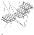
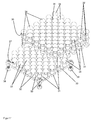
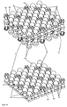
- FIGS. 1 to 7 show a first embodiment of the present invention
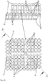
- FIG. 1 a schematic perspective view of five partially connected to each other to an open-pore body or solid plates of a bone substitute material according to the invention
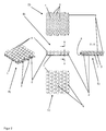
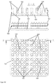
- FIG. 2 shows five schematic views of the two lower plates (base plates) after FIG. 1 , A) as a perspective view, B) as a side view, C) as a top view, D) as a view of the underside and E) as a cross-sectional view along the section AA according to FIG. 2 B)
- FIG. 3 three schematic views of three upper plates (mounting plates) after FIG. 1 , A) as a perspective view, B) as a side view and C) as a top view
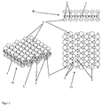
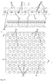
- FIG. 4 shows a schematic perspective view of three differently deeply interlocked plates of the bone substitute material according to the invention to form an open-pore volume body according to the FIGS. 1 to 3 ,
- the plates are made of an elastic biocompatible plastic or stainless steel, titanium, a titanium alloy, tantalum, a tantalum alloy can also be made of composites of these materials.
- the plates are produced using a CAM (Computer Aided Manufacturing) method or a 3D printing method, for example selective SLM (Selective Laser Melting).
- CAM Computer Aided Manufacturing
- SLM Selective Laser Melting
- Other rapid prototyping methods or computer-aided generative manufacturing methods can also be used to manufacture the plates, such as Fused Layer Modeling / Manufacturing (FLM), Fused Deposition Modeling (FDM), Laminated Object Modeling (LOM) of plastic films, Layer Laminated Manufacturing (FLM).
- FLM Fused Layer Modeling / Manufacturing
- FDM Fused Deposition Modeling
- LOM Laminated Object Modeling
- LLM low-density plastic films
- EBM electron beam melting
- MLM multi-jet modeling
- SLS selective laser sintering
- STL or SLA stereolithography
- DLP Digital Light Processing
- the plates each have a plate-shaped sheet 1, which carries the entire plates and connects to each other.
- the sheet 1 is flexible and elastically deformable, so that other surfaces can be formed as planes with the sheet 1.
- a plurality of pins 2 extend in each plate, which protrude perpendicularly from the plane of the sheet 1.
- a plurality of through recesses 3 are arranged between the pins 2, which, when the plates are connected to each other into a solid, cause an open porosity of the solid in a direction perpendicular to the sheets 1.
- FIGS. 1 to 7 For example, two different types of plates are shown, namely, base plates that have a flat underside, and in which the pins 2 extend only on one side of the sheet 1 from the sheet 1 extend, and secondly building boards, in which the pins 2 extend from both sides of the sheet 1 from.
- the base plates are in FIG. 1 below, in FIG. 2 , in FIG. 4 down and in FIG. 5 shown below.
- the mounting plates are in FIG. 1 on top, in FIG. 3 , in FIG. 4 on top, in FIG. 5 on top and the FIGS. 6 and 7 shown.
- the base plates can be attached over a large area adjacent to the bone to be treated. However, the mounting plates can also be mounted on the bone to be treated, albeit with a smaller contact surface, so that theoretically can be dispensed with the base plates.
- mushrooms 4 are provided as connecting elements 4 at the opposite ends of the sheets 1 of the pins.
- the mushrooms 4 are rounded outward (away from the sheet 1) and form spherical sections. But there are also other rounding, such as elliptical sections possible.
- the mushrooms 4 On the side facing the fabric 1, the mushrooms 4 form a flat gripping surface 6, which are suitable for hooking with other mushrooms 4 engaging plates or with the recesses 3 engaging plates.
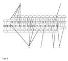
- FIG. 5 1 shows a schematic side view of two plates of the bone substitute material according to the invention, which are hooked to one another only via the mushrooms 4,
- FIG. 6 a schematic side view of two on the mushrooms 4 and the recesses 3 of the sheet 1 with each other latched plates of the bone replacement material according to the invention and
- FIG. 7 a schematic cross-sectional view of the two on the mushrooms 4 and on the recesses 3 of the sheet 1 with each other latched plates, as in FIG. 6 shown.
- the plates are preferably adjacent to one another but not hooked or latched, so that the mushrooms 4 of the pins 2 of adjacent plates do not mesh with one another.
- the plates may be wetted with a liquid.
- the liquid preferably contains at least one pharmaceutically active substance which is suitable for controlling the infection or for stimulating bone growth.
- the plates may be coated with such a pharmaceutically active substance.
- the bone substitute material can be formed by pressing the plates into each other across their surfaces. As a result, the plates interlock or snap together and the bone substitute material is solidified in the desired shape.
- the plates can also be deformed by elastic deformation of the fabric 1 and adapted to the treatment situation. After hooking or catching with at least one other (usually then also deformed) plate, the two so interconnected plates stabilize each other, so that the selected shape is solidified.
- the plates connect to each other in such a way that free spaces between the interconnected plates in the region of the pins 2 and the mushrooms 4 remain, so that the volume formed from the plates is also porous in the directions parallel to the plane of the plates.
- the plates have a cross section or a thickness of about 5 mm, so that the remaining pores have a free cross section in the range of about 0.5 mm. This cross section is sufficient so that bone material can form or grow in the pores.
- the solid with its open pores can therefore be called osteoconductive.
- the formed from the plates volume is therefore well suited as a bone substitute material.
- the plates should be pressed tightly together so that the solid is dimensionally stable.
- the plates may in a first step get caught with each other by the mushrooms 4 elastically deforming the pins 2 of connected plates and by the elastic restoring force of the pins 2 the mushrooms 4 limit the movement of adjacent plates away from the sheet 1 (see FIG. 5 ).
- the plates can, by further pressing of the plates in a second stage with each other snap together by the mushrooms 4 are pushed through the recesses 3 of the sheet 1. This can lead to jamming of the mushrooms 4 with the recesses 3, which prevents movement of the mushrooms 4 against the adjacent plate and thus the two plates locked together.
- the edges of the mushrooms 4 plastically deform the pins 2 or the recesses 3 or the mushrooms 4 or, secondly, the edges of the recesses 3, the mushrooms 4 of adjacent plates to a small extent, thereby locking the plates together.
- Two plates can also be connected to each other by the plates are hooked together in some areas on the mushrooms 4 and in other areas on the mushrooms 4 and recesses 3 with each other be rested.
- the dimensions of the mushrooms 4, the depth of the recesses 3 (or the thickness of the sheet 1) and the length of the pins 2 between the sheet 1 and the mushrooms 4 are preferably matched to one another such that, when the plates get caught, the sheets of the sheet 1 facing away from surfaces of the mushrooms 4 on the surface of the sheet 1 of adjacent plates and rest on a rest of the plates facing away from the fabric 1 surfaces of the mushrooms 4 on the gripping surface 6 of the mushrooms 4 of the adjacent plate. This ensures that the plates are neither against each other during hooking or snapping without deformation.
- the recesses 3 each have six slots which are distributed over the circumference of the recesses 3.
- the width of the slits should be sufficient for them to be osteoconductive.
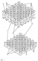
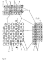
- FIG. 8 Fig. 4 shows four schematic views of interconnected plates of a second alternative bone substitute material in A) a perspective view, B) a side view, C) a top view, and D) a cross-sectional view along the section CC FIG. 8C) ,
- the plates are made of stainless steel, titanium, a titanium alloy, tantalum, a tantalum alloy but can also be made of an elastic biocompatible plastic or a composite of metallic materials.
- the plates are produced by a CAM method or a 3D printing method, for example with selective electron beam melting (EBM). Other rapid prototyping methods or computer-aided generative manufacturing methods can also be used for the production of the plates.
- the plates each have a plate-shaped sheet 11 which carries the entire plates and connects to each other.
- the sheet 11 is flexible and elastically deformable, so that other surfaces can be formed as planes with the sheet 11.
- each plate has a plurality of pins 12 extending perpendicularly from the plane of the sheets 11.
- a plurality of through recesses 13 are arranged between the pins 12, which when the plates are joined together to form a solid, an open porosity of the bulk body in a direction perpendicular to the sheets 11 can be achieved, if the adjacent plates do not abut and thereby cover the recesses 13.
- FIG. 8 only one of the two types of plates is shown, namely mounting plates, in which the pins 12 extend from both sides of the sheet 11 from. It may also be provided base plates, in which a flat bottom is provided and in which the pins 12 extend only on one side of the sheet 11 of the sheet 11 from. Such base plates can be attached over a large area adjacent to the bone to be treated. However, the mounting plates shown can also be attached to the bone to be treated, albeit with a smaller contact surface, so that can be dispensed with the base plates.
- mushrooms 14 are provided as connecting elements 14 at the flat surfaces 11 of the opposite ends of the pins 12 and in the middle between the ends of the pins 12 and the sheets 11.
- the mushrooms 14 are rounded outward (away from the sheet 11) and form spherical sections. But there are also other rounding, such as elliptical sections possible.
- the mushrooms 14 form a flat gripping surface 16 suitable for hooking with other mushrooms 14 of engaging plates or with the recesses 13 engaging plates.
- the plates abut one another but are not hooked or latched with one another (ie not as in FIG FIG. 8 shown), so that the mushrooms 14 of the pins 12 of adjacent plates do not mesh yet.
- the plates may be wetted with a liquid.
- the liquid preferably contains at least one pharmaceutically active substance which is suitable for controlling the infection or for stimulating bone growth.
- the plates may be coated with such a pharmaceutically active substance.
- the bone substitute material can be formed by pressing the plates into each other across their surfaces. As a result, the plates snag or snap together and the bone substitute material is in the desired shape solidified.
- the plates can also be deformed by elastic deformation of the fabric 11 and adapted to the treatment situation. After hooking or catching with at least one other (usually then also deformed) plate, the two plates so interconnected stabilize each other, so that the selected shape is solidified.
- the plates are mutually connected in such a way that free spaces remain between the interconnected plates in the region of the pins 12 and the mushrooms 14, so that the volume formed by the plates is open-pored in the directions parallel to the plane of the plates.
- the plates have a cross-section or a thickness of about 9 mm, so that the remaining pores have a free cross-section in the range of about 0.5 mm. This cross section is sufficient so that bone material can form or grow in the pores.
- the solid with its open pores can therefore be called osteoconductive.
- the formed from the plates volume is therefore well suited as a bone substitute material.
- the plates should be pressed tightly together so that the solid is dimensionally stable.
- the plates may catch each other in a first step as the mushrooms 14 elastically deform the pins 12 of connected plates and, by the elastic restoring force of the pins 12, the mushrooms 14 limit the movement of adjacent plates away from the sheet 11.
- the plates can snap together by pushing the outer mushrooms 14 through the recesses 13 of the sheets 11, as in FIG FIG. 8 shown. This can lead to jamming of the outer mushroom 14 with the recesses 13, which prevents movement of the mushroom 14 against the adjacent plate and thus the two plates locked together.
- the edges of the mushrooms 14 plastically deform the pins 12 or the recesses 13 or the mushrooms 14 or, secondly, the edges of the recesses 13, the mushrooms 14 of adjacent plates to a small extent and thereby latching the plates together.
- a first entanglement also takes place when the outer mushrooms 14 of adjacent plates interlock.
- Two plates can also be connected to each other by the plates are hooked together in some areas on the mushrooms 14 and locked in other areas on the mushrooms 14 and recesses 13 with each other.
- the gripping surfaces 16 or the opposite cap tops of the mushrooms 14 not completely shoot the recesses 13 and thus the recesses 13 are easily deformed by the mushrooms 14, the recesses 13 may have a plurality of slots (not shown) which distributed over the circumference of the recesses 13 are.
- the width of the slits should be sufficient for them to be osteoconductive.
- FIG. 8 So it differs from the after the FIGS. 1 to 7 especially in that the pins 12 have two mushrooms 14 spaced apart from each other. In addition, the recesses 13 have no additional slots.
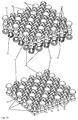
- FIG. 9 Figure 4 shows four schematic views of interconnected plates of a third alternative bone substitute material. It shows FIG. 9A) a perspective view, FIG. 9B) a side view, FIG. 9C) a top view on the top and FIG. 9D) a cross-sectional view along the section BB after FIG. 9C) ,
- the plates are made of titanium or a titanium alloy, tantalum or a tantalum alloy but can also be made of stainless steel, an elastic biocompatible plastic or a composite of such materials.
- the plates are produced by a CAM method or a 3D printing method, for example with selective electron beam melting (EBM).
- EBM selective electron beam melting
- Other rapid prototyping methods or computer-aided generative manufacturing methods can also be used for the production of the plates.
- the plates each have a plate-shaped sheet 21 which carries and connects the entire plates.
- the sheet 21 is flexible and elastically deformable, so that other surfaces than planes with the fabric 21 can be formed.
- each plate has a plurality of pins 22 extending perpendicularly from the plane of the sheets 21.
- the pins 22 there are disposed between the pins 22 a plurality of through recesses 23 which, when the plates are joined together to form a solid, can cause an open porosity of the solid in a direction perpendicular to the sheets 21, if not the adjacent sheets abut and thereby cover the recesses 23.
- FIG. 9 Only one of the two types of plates is shown, namely mounting plates, in which the pins 22 extend from both sides of the sheet 21 from.
- Base plates may also be provided in which a flat underside is provided and in which the pins 22 extend from the sheet 21 only on one side of the sheet 21.
- Such base plates can be attached over a large area adjacent to the bone to be treated.
- the mounting plates shown can also be attached to the bone to be treated, albeit with a smaller contact surface, so that can be dispensed with the base plates.
- mushrooms 24 are provided as connecting elements 24 at the opposite ends of the sheets 21 of the pins.
- the mushrooms 24 are rounded outwards (away from the sheet 21) and form spherical sections. But there are also other rounding, such as elliptical sections possible.
- the mushrooms 24 form a flat gripping surface 26 suitable for hooking or snapping with other mushrooms 24 engaging plates or plates engaging with the recesses 23.
- the plates abut one another but are not hooked or latched with one another (ie not as in FIG FIG. 9 shown), so that the mushrooms 24 of the pins 22 adjacent plates do not yet interlock.
- the plates may be wetted with a liquid.
- the liquid is preferably at least one pharmaceutically effective Contain substance that is suitable for controlling the infection or to stimulate bone growth.
- the plates may be coated with such a pharmaceutically active substance.
- the bone substitute material can be formed by pressing the plates into each other across their surfaces. As a result, the plates interlock or snap together and the bone substitute material is solidified in the desired shape.
- the plates can also be deformed by elastic deformation of the fabric 21 and adapted to the treatment situation. After hooking or catching with at least one other (usually then also deformed) plate, the two so interconnected plates stabilize each other, so that the selected shape is solidified.
- the plates connect to each other in such a way that free spaces between the interconnected plates in the region of the pins 22 and the mushrooms 24 remain, so that the volume formed from the plates is open-pored in the directions parallel to the plane of the plates.
- the plates have a cross section or a thickness of about 3 mm, so that the remaining pores have a free cross section in the range of about 0.3 mm. This cross section is sufficient so that bone material can form or grow in the pores.
- the solid with its open pores can therefore be called osteoconductive.
- the formed from the plates volume is therefore well suited as a bone substitute material.
- the plates should be pressed tightly together so that the solid is dimensionally stable.
- the plates may catch in a first step with each other by the mushrooms 24 elastically deforming the pins 22 of connected plates, and by the elastic restoring force of the pins 22 the mushrooms 24 limit the movement of adjacent plates away from the sheet 21.
- the plates can be snapped or latched by forcing the mushrooms 24 through the recesses 23 of the sheets 21, as in FIG FIG. 9 shown. This can lead to jamming of the mushrooms 24 with the recesses 23, which prevents movement of the mushrooms 24 against the adjacent plate and thus the two plates locked together.
- the edges of the mushrooms 24, the pins 22 or the recesses 23 or the mushrooms 24 or, secondly, the edges of the Recesses 23 plastically deform the mushrooms 24 adjacent plates to a small extent, thereby locking the plates together.
- Two plates can also be connected to each other by the plates are hooked together in some areas on the mushrooms 24 and locked in other areas on the mushrooms 24 and recesses 23 with each other.
- the dimensions of the mushrooms 24, the depth of the recesses 23 (or the thickness of the sheet 21) and the length of the pins 22 between the sheet 21 and the mushrooms 24 are matched to one another such that, when the sheets are joined, the sheets of the sheet 21 tillwandten surfaces of the mushrooms 24 abut against the surface of the sheet 21 of adjacent plates and / or abut the plates connecting the plates facing away from the fabric 21 surfaces of the mushrooms 24 on the gripping surface 26 of the mushrooms 24 of the adjacent plate. This ensures that the joined plates are not mutually movable without deformation.
- the gripping surfaces 26 or the opposite cap tops of the mushrooms 24 not completely shoot the recesses 23 and thus the recesses 23 are easily deformed by the mushrooms 24, the recesses 23 may have a plurality of slots (not shown), which distributed over the circumference of the recesses 23 are.
- the width of the slits should be sufficient for them to be osteoconductive.
- FIG. 9 So it differs from the after the FIGS. 1 to 7 especially in that the pins 22 and the recesses 23 have a slightly greater distance from each other. In addition, the recesses 23 have no additional slots.
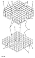
- FIG. 10 shows three schematic views of two interconnected plates of a fourth alternative bone substitute material, A) perspective view, B) top view, C) cross-sectional view along the section AA after FIG. 10B) , and the FIGS. 11 to 13 further variants of the fourth alternative bone replacement material.
- the plates are made of a biocompatible metal such as stainless steel, titanium or a titanium alloy, tantalum or a tantalum alloy but can also be made of elastic biocompatible plastic or a composite of such materials.
- the plates are with a CAM method or a 3D printing process produced, for example, with selective electron beam melting (EBM).
- EBM selective electron beam melting
- Other rapid prototyping methods or computer-aided generative manufacturing methods can also be used for the production of the plates.
- the plates each have a plate-shaped sheet 31 which carries and connects the entire plates.
- the sheet 31 is flexible and elastically deformable, so that other surfaces can be formed as planes with the sheet 31.
- each plate has a plurality of pins 32 extending perpendicularly from the plane of the sheets 31.
- In the sheet 31 there are disposed between the pins 32 a plurality of through recesses 33 which, when the plates are joined together to form a solid, can cause an open porosity of the solid in a direction perpendicular to the sheets 31, if not the adjacent plates abut and thereby cover the recesses 33.
- FIGS. 10 to 13 two different types of plates are shown, namely, base plates having a flat bottom surface and in which the pins 32 extend from the sheet 31 only on one side of the sheets 31, and secondly, mounting plates where the pins 32 are from both sides of the sheet 31 extend from.
- the base plates are in FIG. 10 below or below, in FIG. 11 below, in FIG. 12 up and in FIG. 13A) down and in FIG. 13B) to D) shown.
- the mounting plates are in FIG. 10 on top, in FIG. 11 on top, in FIG. 12 down and in FIG. 13A) shown on top of.
- the base plates can be attached over a large area adjacent to the bone to be treated. However, the mounting plates can also be mounted on the bone to be treated, albeit with a smaller contact surface, so that can be dispensed with the base plates.
- mushrooms 34 are provided as connecting elements 34 at the sheet 31 opposite ends of the pins.
- the mushrooms 34 are rounded outward (away from the sheet 31) and form ball sections. But there are also other rounding, such as elliptical sections possible.
- the Snagging or snapping with other mushrooms 34 engaging plates or with the recesses 33 engaging plates are suitable.
- the pins 32 are also provided adjacent to the gripping surfaces 36 grooves 37 as connecting elements 37, in which the mushrooms 34 adjacent plates can engage or engage.
- the grooves 37 in contrast to the grooves 37 shown, but preferred according to the invention, be formed as a negative of the shape of the curvature of the mushrooms 34 so that the mushrooms 34 fit well in the grooves 37.
- FIG. 11 shows a schematic perspective view of two interconnected via the connecting elements 34 plates of the fourth inventive bone replacement material according to the type FIG. 10 .
- FIG. 12 a schematic perspective view of two non-interconnected plates of the fourth inventive bone replacement material according to the type Figures 10 and 11 and FIG. 13 four schematic views of the fourth alternative bone substitute material in a design with defects in the pins 32
- the plates abut one another but are not hooked or latched with one another (ie not as in FIG FIG. 10A) or 11 or 13A ), so that the mushrooms 34 of the pins 32 of adjacent plates do not mesh with each other yet.
- the plates may be wetted with a liquid.
- the liquid preferably contains at least one pharmaceutically active substance which is suitable for controlling the infection or for stimulating bone growth.
- the plates may be coated with such a pharmaceutically active substance.
- the bone substitute material can be formed by pressing the plates into each other across their surfaces. As a result, the plates interlock or snap together and the bone substitute material is solidified in the desired shape. Previously, the plates can also be deformed by elastic deformation of the sheet 31 and adapted to the treatment situation.
- the two so interconnected plates stabilize each other, so that the selected shape is solidified.
- the plates are mutually connected in such a way that free spaces remain between the interconnected plates in the area of the pins 32, the mushrooms 34 and the grooves 37, so that the volume formed from the plates openly pores in the directions parallel to the plane of the plates is.
- the plates have a cross section or a thickness of about 6 mm, so that the remaining pores have a free cross section in the range of about 0.6 mm. This cross section is sufficient so that bone material can form or grow in the pores.
- the solid with its open pores can therefore be called osteoconductive.
- the formed from the plates volume is therefore well suited as a bone substitute material.
- the plates should be pressed tightly together so that the solid is dimensionally stable.
- the plates can engage in a first stage with each other by the mushrooms 34 elastically deform the pins 32 connected plates and press the mushrooms 34 or the edges of the mushrooms 34 in the grooves 37 by the elastic restoring force of the pins 32 and thereby the movement of adjacent Delimiting plates away from the sheet 31 (see Figures 10 . 11 and 13A ).
- the plates can snap together by further pressing the plates together in a second stage by pushing the mushrooms 34 through the recesses 33 of the sheets 31 (not shown). This can lead to jamming of the mushrooms 34 with the recesses 33, which prevents movement of the mushrooms 34 against the adjacent plate and thus the two plates locked together.
- the edges of the mushrooms 34 plastically deform the pins 32, the grooves 37 or the recesses 33 or the mushrooms 34 or, secondly, the edges of the recesses 33 the mushrooms 34 of adjacent plates and thereby latching the plates with each other.
- Two plates can also be connected to each other by the plates in some areas on the mushrooms 34 and grooves 37 are snapped together and locked in other areas on the mushrooms 34 and recesses 33 with each other.
- the dimensions of the mushrooms 34, the depth of the Recesses 33 (or the thickness of the sheet 31), the shape of the grooves 37 and the length of the pins 32 between the sheet 31 and the mushrooms 34 are coordinated so that when connecting the plates facing away from the fabric 31 surfaces of the mushrooms 34th abutting the surface of the sheet 31 of adjacent plates and / or in connecting the plates facing away from the fabric 31 surfaces of the mushrooms 34 on the gripping surface 36 of the mushrooms 34 and preferably along at least one line or more preferably flat on the grooves 37 of the pins 32 abut the adjacent plate. This ensures that the joined plates are not mutually movable without deformation.
- the grooves 37 also prevent the gripping surfaces 36 or the opposite cap tops of the mushrooms 34 completely covering the recesses 33.
- the recesses 33 are easily deformed by the mushrooms 34, the recesses 33 may have a plurality of slots (not shown), which are distributed over the circumference of the recesses 33.
- the width of the slits should be sufficient for them to be osteoconductive.
- the fourth embodiment according to the FIGS. 10 to 13 So it differs from the after the FIGS. 1 to 7 especially because the pins 32 are thicker and have grooves 37 as additional connecting elements. In addition, the recesses 33 have no additional slots.
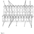
- FIG. 14 shows a schematic perspective view of two interconnected via the connecting plates plates of a fifth inventive bone substitute material.
- FIG. 15 Figure 3 shows three schematic views of the two interconnected plates of the fifth alternative bone substitute material FIG. 14 , in fact FIG. 15A) a top view, FIG. 15B) a side view and FIG. 15C) a cross-sectional view along the section BB after FIG. 15A) ,
- the plates are made of a biocompatible metal, in particular of stainless steel, titanium or a titanium alloy, tantalum or a tantalum alloy but can also be made of an elastic biocompatible plastic or a composite of such materials.
- the plates are produced by a CAM method or a 3D printing method, for example with selective electron beam melting (EBM).
- EBM selective electron beam melting
- Other rapid prototyping methods or computer-aided generative manufacturing methods can also be used for the production of the plates.
- the plates each have a plate-shaped sheet 41 which carries and connects the entire plates.
- the sheet 41 is flexible and elastically deformable, so that surfaces other than planes can be formed with the sheet 41.
- each plate has a plurality of pins 42 extending perpendicularly from the plane of the sheets 41.
- FIG. 14 and 15 two different types of plates are shown, namely, base plates that have a flat bottom surface and in which the pins 42 extend from the sheet 41 only on one side of the sheets 41, and secondly, mounting plates in which the pins 42 extend from both sides of the fabric 41 extend from.
- the base plates are in FIG. 14 below or below, in FIG. 15A) below (in the picture plane), in FIG. 15B) down and in FIG. 15C) shown on the right.
- the mounting plates are in FIG. 14 , in FIG. 15A) above (from the image plane), in FIG. 15B) up and in FIG. 15C) shown on the left.
- the base plates can be attached over a large area adjacent to the bone to be treated.
- the mounting plates can also be mounted on the bone to be treated, albeit with a smaller contact surface, so that can be dispensed with the base plates.
- mushrooms 44 or groups of four hooks 45 are provided as connecting elements 44, 45 at the flat surfaces 41 opposite ends of the pins.
- the mushrooms 44 are rounded outward (away from the sheet 41) and form ball sections. But there are also other rounding, such as elliptical sections possible.
- the hooks 45 are rounded in the same way to the outside.
- On the side facing the fabric 41 towards the mushrooms 44 form a flat gripping surface 46, which for hooking or snapping with other mushrooms 44 and hook 45th engaging plates or with the recesses 43 engaging plates are suitable.
- the hooks 45 on the side facing the fabric 41 form undercuts which are suitable for hooking or catching with other mushrooms 44 and hooks 45 of engaging plates or with the recesses 43 of engaging plates.
- the pins 42 are also provided adjacent to the gripping surfaces 46 and adjacent to the hooks 45 grooves 47 as connecting elements 47, in which the mushrooms 44 and hooks 45 adjacent plates can engage or engage.
- the grooves 47 in contrast to the grooves 47 shown, but preferred according to the invention, be formed as a negative of the shape of the curvature of the mushroom 44 and the hook 45 so that the mushrooms 44 and hooks 45 fit well into the grooves 47.
- only hooks 45 are provided as connecting elements 45 on the base plate and provided on the mounting plate exclusively mushrooms 44 as connecting elements 44. This can also be reversed and the hooks 45 and mushrooms 44 can also be mixed.
- the plates abut one another but are not hooked or latched with one another (ie not as in FIG FIG. 14 or 15 shown), so that therefore the mushrooms 44 and hooks 45 of the pins 42 of adjacent plates do not interlock yet.
- the plates may be wetted with a liquid.
- the liquid preferably contains at least one pharmaceutically active substance which is suitable for controlling the infection or for stimulating bone growth.
- the plates may be coated with such a pharmaceutically active substance.
- the bone substitute material can be formed by pressing the plates into each other across their surfaces. As a result, the plates interlock or snap together and the bone substitute material is solidified in the desired shape.
- the plates can also be deformed by elastic deformation of the fabrics 41 and adapted to the treatment situation. After hooking or catching with at least one other (usually then also deformed) plate, the two plates so interconnected stabilize each other, so that the selected shape is solidified.
- the plates connect to each other in such a way that free spaces between the interconnected plates in the region of the pins 42, the mushrooms 44, the hook 45 and the grooves 47 remain so that the volume formed from the plates in the directions parallel to Level of the plates is porous.
- the plates have a cross-section or a thickness of about 7 mm, so that the remaining pores have a free cross-section in the range of about 0.7 mm. This cross section is sufficient so that bone material can form or grow in the pores.
- the solid with its open pores can therefore be called osteoconductive.
- the formed from the plates volume is therefore well suited as a bone substitute material.
- the plates should be pressed tightly together so that the solid is dimensionally stable.
- the plates can thereby snap together in a first stage by the mushrooms 44 and hooks 45 elastically deforming the pins 42 of connected plates and by the elastic restoring force of the pins 42 the mushrooms 44 and hooks 45 and the edges of the mushrooms 44 and tips of the hooks 45 in the grooves 47 and thereby limit the movement of adjacent plates of the fabric 41 away (see Figures 14 and 15 ).
- the plates can snap together by further pushing the plates together in a second stage by pushing the mushrooms 44 and hooks 45 through the recesses 43 of the sheets 41 (not shown).
- Two plates can also be connected to each other by the plates in some areas on the mushrooms 44, hooks 45 and grooves 47 are locked together and locked in other areas on the mushrooms 44 and hooks 45 with the recesses 43.
- the dimensions of the mushrooms 44, the hook 45, the depth of the recesses 43 (or the thickness of the sheet 41), the shape of the grooves 47 and the length of the pins 42 between the fabric 41 and the mushrooms 44 or hooks 45 are matched to one another in such a way that, when the sheets are joined, the surfaces of the mushrooms 44 and hooks 45 facing away from the fabric 41 rest against the surface of the sheets 41 of adjacent sheets and / or when the sheets are joined the surfaces of the mushrooms 44 and hooks 45 facing away from the fabric 41 against the gripping surface 46 of the mushrooms 44 and preferably along at least one line or more preferably flatly against the grooves 47 of the pins 42 of the adjacent plate. This ensures that the joined plates are not mutually movable without deformation.
- the grooves 47 also prevent the gripping surfaces 46 or the opposite cap tops of the mushrooms 44 or the hooks 45 from completely covering the recesses 43.
- the recesses 43 are easily deformed by the mushrooms 44 and hook 45, the recesses 43 may have a plurality of slots (not shown), which are distributed over the circumference of the recesses 43. The width of the slits should be sufficient for them to be osteoconductive.
- the fifth embodiment according to Figures 14 and 15 So it differs from the after the FIGS. 1 to 7 especially in that the pins 42 are thicker and have grooves 47 and in that hooks 45 are provided as connecting elements 45. In addition, the recesses 43 have no additional slots.
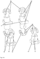
- FIG. 16 shows a schematic perspective view of two interlocked plates of a sixth inventive bone replacement material
- FIG. 17 a schematic perspective view of two non-interlocked plates of the sixth bone replacement material according to the invention
- FIG. 18 shows a schematic side view of interlocked plates of the sixth bone replacement material according to the invention FIG. 16
- FIG. 19 a schematic perspective detail view of two hooks hooked together (left) two hooks not hooked together (right) of the sixth bone replacement material according to the invention FIGS. 16 to 18 ,
- the plates consist of a biocompatible material, in particular of stainless steel, titanium or a titanium alloy, tantalum or a tantalum alloy or of an elastic biocompatible plastic. You can also choose from one Made of composite materials such.
- the plates are produced by a CAM method or a 3D printing method. The rapid prototyping methods or computer-assisted generative production methods mentioned in relation to the other exemplary embodiments can be used to produce the plates.
- the plates each have a plate-shaped sheet 51 which carries and connects the entire plates.
- the sheet 51 is flexible and elastically deformable, so that other surfaces than planes can be formed with the sheet 51.
- each plate has a plurality of pins 52 extending perpendicularly from the plane of the sheets 51.
- the pins 52 there are arranged between the pins 52 a plurality of through recesses 53 which, when the plates are joined together to form a solid, cause an open porosity of the solid in a direction perpendicular to the sheets 51.
- FIGS. 16 to 18 For example, two different types of plates are shown, namely, base plates having a flat bottom surface and with the pins 52 extending from the sheet 51 only on one side of the sheets 51, and secondly, mounting plates having the pins 52 from both sides of the sheet 51 extend from.
- the base plates are in FIG. 16 below or below, in FIG. 17 and 18 shown below.
- the mounting plates are in FIG. 16 on top and in the Figures 17 and 18 shown on top of.
- the base plates can be attached over a large area adjacent to the bone to be treated. However, the mounting plates can also be mounted on the bone to be treated, albeit with a smaller contact surface, so that can be dispensed with the base plates.
- hooks 55 are provided as connecting elements 55 at the opposite ends of the sheets 51.
- the hooks 55 are rounded outwardly (away from the sheet 51) and form parts of spherical surfaces. But there are also other rounding, such as elliptical sections possible.
- the hooks 55 form on the side facing the fabric 51 Undercuts that are suitable for hooking or snapping with other hooks 55 engaging plates or with the recesses 53 engaging plates.
- the pins 52 are formed in the area adjacent to the hooks 55 and the undercuts of the hooks 55 thinner or with a smaller cross-section. In the thinner areas, the hooks 55 adjacent plates can easily engage or snap.
- the plates abut one another but are not hooked or latched with one another (ie not as in FIG FIG. 16 or 18 shown), so that the hook 55 of the pins 52 adjacent plates do not yet interlock.
- the plates may be wetted with a liquid.
- the liquid preferably contains at least one pharmaceutically active substance which is suitable for controlling the infection or for stimulating bone growth.
- the plates may be coated with such a pharmaceutically active substance.
- the bone substitute material can be formed by pressing the plates into each other across their surfaces. As a result, the plates interlock or snap together and the bone substitute material is solidified in the desired shape.
- the plates can also be deformed by elastic deformation of the fabric 51 and adapted to the treatment situation. After hooking or catching with at least one other (usually then also deformed) plate, the two plates so interconnected stabilize each other, so that the selected shape is solidified. The hooking is in FIG. 19 shown in detail.
- the plates connect to each other in such a way that free spaces between the interconnected plates in the region of the pins 52 and the hook 55 remain so that the volume formed from the plates is open-pore in the directions parallel to the plane of the plates.
- the plates have a cross section or a thickness of about 5 mm, so that the remaining pores have a free cross section in the range of about 0.5 mm. This cross section is sufficient so that bone material can form or grow in the pores.
- the solid with its open pores can therefore be called osteoconductive.
- the formed from the plates volume is therefore well suited as a bone substitute material.
- the plates should be pressed tightly together so that the solid is dimensionally stable.
- the plates can snap together in a first stage by the hooks 55 elastically deforming the pins 52 of connected plates and pressing the hooks 55 and tips of the hooks 55 into each other by the elastic restoring force of the pins 52 and thereby the movement of adjacent plates from the sheet Limit 51 away (see Figures 16 . 18 and 19 ).
- the plates can snap together by further pressing the plates together in a second stage by pushing the hooks 55 through the recesses 53 of the sheets 51 (not shown). This can lead to a jamming of the hook 55 with the recesses 53, which prevents movement of the hook 55 against the adjacent plate and thus the two plates locked together.
- Two plates can also be interconnected by the plates are snapped together in some areas on the hooks 55 and snapped in other areas on the hooks 55 with the recesses 53.
- the dimensions of the hooks 55, the depth of the recesses 53 (or the thickness of the sheet 51) and the length of the pins 52 between the sheet 51 and the hook 55 are coordinated so that when connecting the plates of the sheet 51st facing away from the hooks 55 abut the surface of the sheet 51 of adjacent plates and / or in a connection of the plates abut the side facing away from the sheet 51 sides of the hooks 55 in the undercuts of the hook 55. This ensures that the joined plates are not mutually movable without deformation.
- the shape of the hooks 55 prevents them from completely covering the recesses 53.
- the recesses 53 are easily deformed by the hooks 55, the recesses 53 may have a plurality of slots (not shown), which are distributed over the circumference of the recesses 53.
- the sixth embodiment according to the FIGS. 16 to 19 differs from the after the FIGS. 1 to 7 above all, in that the pins 52 are thicker in regions and, in particular, in that hooks 55 are provided as connecting elements 55. In addition, the recesses 53 have no additional slots.
- FIG. 20 shows a schematic perspective view of two non-interlocked plates of a seventh bone replacement material according to the invention and FIG. 21 three schematic views of two interconnected plates of the seventh alternative bone substitute material A) as a top view, B) as a side view and C) as a cross-sectional view along the section BB after FIG. 21A) ,
- the plates are made of a biocompatible metal, in particular of stainless steel, titanium or a titanium alloy, tantalum or a tantalum alloy but can also be made of an elastic biocompatible plastic or a composite of such materials.
- the plates are produced by a CAM method or a 3D printing method, for example with selective electron beam melting (EBM).
- EBM selective electron beam melting
- Other rapid prototyping methods or computer-aided generative manufacturing methods can also be used for the production of the plates.
- the plates each have a plate-shaped sheet 61 which carries and connects the entire plates.
- the sheet 61 is flexible and elastically deformable, so that surfaces other than planes can be formed with the sheet 61.
- each plate has a plurality of pins 62 extending perpendicularly from the plane of the sheets 61.
- Disposed within the sheet 61 are a plurality of through recesses 63 between the pins 62 which, when joined together to form a solid, may cause an open porosity of the solid in a direction perpendicular to the sheets 61, if not the adjacent sheets abut and thereby cover the recesses 63.
- FIG. 20 and 21 For example, two different types of plates are shown, namely, base plates that have a flat bottom surface and in which the pins 62 extend only on one side of the sheets 61 of the sheet 61, and secondly mounting plates, in which the pins 62 extend from both sides of the sheet 61 from.
- the base plates are in FIG. 20 below, in FIG. 21A) below (in the picture plane), in FIG. 21B) down and in Figure 21C) shown on the right.
- the mounting plates are in FIG. 20 up and in FIG. 21 on top, so in FIG. 21A) above (from the image plane), in FIG. 21B) up and in Figure 21C) shown on the left.
- the base plates can be attached over a large area adjacent to the bone to be treated.
- the mounting plates can also be mounted on the bone to be treated, albeit with a smaller contact surface, so that can be dispensed with the base plates.
- mushrooms 64 or groups of four hooks 65 are provided as connecting elements 64, 65 at the opposite ends of the sheets 61 of the pins.
- the mushrooms 64 are rounded outwardly (away from the sheet 61) and form ball sections. But there are also other rounding, such as elliptical sections possible.
- the hooks 65 are rounded in the same way to the outside.
- the mushrooms 64 form a flat gripping surface 66 suitable for hooking or snapping with other mushrooms 64 and hooks 65 engaging plates or with the recesses 63 engaging plates. Accordingly, the hooks 65 on the side facing the fabric 61 undercut, which are suitable for snagging or latching with other mushrooms 64 and hooks 65 engaging plates or with the recesses 63 engaging plates.
- the pins 62 are also adjacent to the gripping surfaces 66 and adjacent to the hooks 65 grooves 67 as connecting elements 67, into which the mushrooms 64 and hooks 65 adjacent plates can engage or engage.
- the grooves 67 may be formed as a negative of the shape of the curvature of the mushrooms 64 or of the hooks 65, so that the mushrooms 64 and hooks 65 fit well into the grooves 67.
- mushrooms 64 and hooks 65 are mixedly provided on the plates as connecting members 64, 65, wherein two of eleven connecting members 64, 65 are hooks 65 and the remainder are mushrooms 64 may also be reversed and the hooks 65 and mushrooms 64 may also be in a different mixing ratio.
- the plates abut one another but are not hooked or latched with one another (ie not as in FIG FIG. 21 ), so that the mushrooms 64 and hooks 65 of the pins 62 of adjacent plates do not mesh with each other yet.
- the plates may be wetted with a liquid.
- the liquid preferably contains at least one pharmaceutically active substance which is suitable for controlling the infection or for stimulating bone growth.
- the plates may be coated with such a pharmaceutically active substance.
- the bone substitute material can be formed by pressing the plates into each other across their surfaces. As a result, the plates interlock or snap together and the bone substitute material is solidified in the desired shape.
- the plates can also be deformed by elastic deformation of the fabric 61 and adapted to the treatment situation. After hooking or catching with at least one other (usually then also deformed) plate, the two so interconnected plates stabilize each other, so that the selected shape is solidified.
- the plates are mutually connected in such a way that free spaces remain between the interconnected plates in the area of the pins 62, the mushrooms 64, the hooks 65 and the grooves 67, so that the formed of the plates volume body in the directions parallel to Level of the plates is porous.
- the plates have a cross section or thickness of about 9 mm, so that the remaining pores have a free cross section in the range of about 0.9 mm. This cross section is sufficient so that bone material can form or grow in the pores.
- the solid with its open pores can therefore be called osteoconductive.
- the formed from the plates volume is therefore well suited as a bone substitute material.
- the plates should be pressed tightly together so that the solid is dimensionally stable.
- the plates can in a first step with each other by the mushrooms 64 and hooks 65 elastically deform the pins 62 connected plates and by the elastic restoring force of the pins 62, the mushrooms 64 and Hook 65 or the edges of the mushrooms 64 and tips of the hooks 65 press into the grooves 67 and thereby limit the movement of adjacent plates away from the sheet 61 (see FIG. 21 ).
- the plates can snap together by further pressing the plates together in a second stage by pushing the mushrooms 64 and hooks 65 through the recesses 63 of the sheets 61 (not shown).
- Two plates can be further interconnected by the plates in some areas on the mushrooms 64, hook 65 and grooves 67 are locked together and locked in other areas on the mushrooms 64 and / or hooks 65 with the recesses 63.
- the dimensions of the mushrooms 64, the hook 65, the depth of the recesses 63 (or the thickness of the sheet 61), the shape of the grooves 67, and the length of the pins 62 between the sheet 61 and the mushrooms 64 or hooks 65 are so superimposed that the surfaces of the mushrooms 64 and hooks 65 facing away from the fabric 61 abut against the surface of the sheets 61 of adjacent plates and / or when connecting the plates, the surfaces of the mushrooms 64 and hooks facing away from the fabric 61 65 on the gripping surface 66 of the mushrooms 64 and preferably along at least one line or more preferably lie flat against the grooves 67 of the pins 62 of the adjacent plate. This ensures that the joined plates are not mutually movable without deformation.
- the grooves 67 also prevent the gripping surfaces 66 or the opposite cap tops of the mushrooms 64 or hooks 65 from completely covering the recesses 63.
- the recesses 63 are easily deformed by the mushrooms 64 and hooks 65, the recesses 63 may have a plurality of slots (not shown), which are distributed over the circumference of the recesses 63.
- the width of the slits should be sufficient for them to be osteoconductive.
- the fifth embodiment according to Figures 20 and 21 So it differs from the after the FIGS. 1 to 7 especially in that the pins 62 are thicker and have grooves 67 and in that hooks 65 are provided as connecting elements 65. In addition, the recesses 63 have no additional slots.
- FIG. 22 shows a schematic perspective view of two non-interlocked plates of an eighth bone replacement material according to the invention and FIG. 23 three schematic views of two interconnected plates of the eighth alternative bone substitute material, FIG. 23A) a top view, FIG. 23B) a side view and FIG. 23C) a cross-sectional view along the section CC after FIG. 23A) ,
- FIG. 24 shows a schematic perspective view of two non-interlocked plates of a modification of the eighth bone replacement material according to the invention and FIG. 25 three schematic views of two interconnected plates of the modification of the eighth alternative bone substitute material, FIG. 25A) a top view, FIG. 25B) a side view and FIG. 25C) a cross-sectional view along the section CC after FIG. 23A) ,
- the plates are made of a titanium or a titanium alloy, tantalum or a tantalum alloy can also be made of another elastic biocompatible material.
- the plates are produced by a CAM method or a 3D printing method, for example with selective electron beam melting (EBM). Other rapid prototyping methods or computer-aided generative manufacturing methods can also be used for the production of the plates.
- the plates each have a plate-shaped sheet 71 which carries and connects the entire plates.
- the sheet 71 is flexible and elastically deformable, so that other surfaces than planes can be formed with the sheet 71.
- each plate has a plurality of pins 72 extending perpendicularly from the plane of the sheets 71.
- a plurality of through recesses 73 are arranged between the pins 72, which, when the plates are connected together to form a solid, an open Porosity of the volume body in a direction perpendicular to the sheets 71 can cause, if not abut the adjacent plates and thereby cover the recesses 73.
- FIGS. 22 to 25 For example, two different types of plates are shown, namely, base plates having a flat bottom surface and with the pins 72 extending from the sheet 71 on only one side of the sheets 71, and secondly, mounting plates having the pins 72 from both sides of the sheet 71 extend from.
- the base plates are in FIG. 22 below, in FIG. 23A) below (in the picture plane), in FIG. 23B) down and in FIG. 23C) shown on the right as well as in FIG. 24 below, in FIG. 25A) below (in the picture plane), in FIG. 25B) down and in FIG. 25C) shown on the right.
- the mounting plates are in FIG. 22 and 24 up and in FIG. 23 on top, so in FIG.
- the base plates can be attached over a large area adjacent to the bone to be treated.
- the mounting plates can also be mounted on the bone to be treated, albeit with a smaller contact surface, so that can be dispensed with the base plates.
- mushrooms 74 or groups of four hooks 75 are provided as connecting elements 74, 75 at the opposite ends of the sheets 71 of the pins.
- the mushrooms 74 are rounded outwards (away from the sheet 71) and form spherical sections. But there are also other rounding, such as elliptical sections possible.
- the hooks 75 are rounded in the same way to the outside.
- the mushrooms 74 On the side facing the sheet 71, the mushrooms 74 have undercuts 76 which are suitable for hooking or snapping with hooks 75 of engaging plates.
- the hooks 75 on the side facing the sheet 71 form undercuts which are suitable for hooking or latching with other mushrooms 74 and hooks 75 of engaging plates or with the recesses 73 of engaging plates.
- pins 72 are also provided adjacent to the undercuts 76 and adjacent to the hooks 75 grooves 77 as connecting elements 77, in which engage and engage the mushrooms 74 and hooks 75 adjacent plates can.
- the edges 71 of the grooves 77 facing the sheet 71 are formed rounded, so that the mushrooms 74 and hooks 75 fit well into the grooves 77 or slide.
- mushrooms 74 and hooks 75 are mixedly provided on the plates as connecting members 74, 75.
- the variant of the Figures 22 and 23 are two of eleven fasteners 74, 75 hooks 75 and the rest mushrooms 74.
- Eight of eleven fasteners 74, 75 are hooks 75 and the remainder are mushrooms 74. This may be the other way around, and hooks 75 and mushrooms 74 may also be in a different mix ratio.
- the plates abut each other but not hooked together or latched (ie not as in the FIG. 23 and 25 ), so that the mushrooms 74 and hooks 75 of the pins 72 of adjacent plates do not mesh with each other yet.
- the plates may be wetted with a liquid.
- the liquid preferably contains at least one pharmaceutically active substance which is suitable for controlling the infection or for stimulating bone growth.
- the plates may be coated with such a pharmaceutically active substance.
- the bone substitute material can be formed by pressing the plates into each other across their surfaces. As a result, the plates interlock or snap together and the bone substitute material is solidified in the desired shape.
- the plates can also be deformed by elastic deformation of the fabric 71 and adapted to the treatment situation. After hooking or catching with at least one other (usually then also deformed) plate, the two so interconnected plates stabilize each other, so that the selected shape is solidified.
- the plates connect to each other in such a way that free spaces between the interconnected plates in the region of the pins 72, the mushroom 74, the hook 75 and the grooves 77 remain so that the volume formed from the plates in the directions parallel to Level of the plates is porous.
- the plates have a cross section or a thickness between 5 mm and 10 mm, so that the remaining pores have a free cross section in the area between about 0.5 mm and 1 mm. This cross section is sufficient so that bone material can form or grow in the pores.
- the solid with its open pores can therefore be called osteoconductive.
- the formed from the plates volume is therefore well suited as a bone substitute material.
- the plates should be pressed tightly together so that the solid is dimensionally stable.
- the plates can thereby snap together in a first stage by the mushrooms 74 and hooks 75 elastically deforming the pins 72 of connected plates and by the elastic restoring force of the pins 72 the mushrooms 74 and hooks 75 or the edges of the mushrooms 74 and tips of the hooks 75 in the grooves 77 and thereby limit the movement of adjacent plates away from the sheet 71 (see Figures 23 and 25 ).
- the plates can snap together by further interlocking of the plates in a second stage by pushing the mushrooms 74 and hooks 75 through the recesses 73 of the sheets 71 (not shown).
- Two plates can be further interconnected by the plates in some areas on the mushrooms 74, hook 75 and grooves 77 are locked together and locked in other areas on the mushrooms 74 and / or hook 75 with the recesses 73.
- the dimensions of the mushrooms 74, the hook 75, the depth of the recesses 73 (or the thickness of the sheet 71), the shape of the grooves 77, and the length of the pins 72 between the sheet 71 and the mushrooms 74 or hooks 75 are so superimposed that the surfaces of the mushrooms 74 and hooks 75 facing away from the fabric 71 abut against the surface of the sheets 71 of adjacent sheets and / or when joining the sheets, the surfaces of the mushrooms 74 and 74 facing away from the fabric 71 Hook 75 in the undercuts 76 of the mushrooms 74 and preferably along at least one line to the grooves 77 of the pins 72 of the adjacent plate. This ensures that the joined plates are not mutually movable without deformation.
- the grooves 77 also prevent the gripping surfaces 76 or the opposing cap tops of the mushrooms 74 or the hooks 75 from completely covering the recesses 73.
- the recesses 73 may have a plurality of slots (not shown) distributed about the circumference of the recesses 73. The width of the slits should be sufficient for them to be osteoconductive.
- the eighth embodiment according to FIGS. 22 to 25 So it differs from the after the Figures 20 and 21 in that the mushrooms 74 have undercuts 76 in which the hooks 75 of adjacent plates can engage.
- FIG. 26 shows a schematic perspective view of three and six pairs of interconnected plates of the eighth alternative bone substitute material and three particles of a bone substitute material, wherein the plates can be connected to the particles.
- the particles are composed of a core located in the geometric center of the particle and twenty pins 82 extending radially away from the core in different directions.
- At the ends of the pins 82 are either mushrooms 84 or a group of four hooks 85 as connecting elements 84, 85 arranged on the otherwise cylindrical pins 82.
- the mushrooms 84 and hooks 85 correspond to the mushrooms 74 and hooks 75 of the plates and are similarly sized.
- the mushrooms 84 and the hooks 85 are accordingly spherically rounded outwardly (away from the core). There are also other rounding, such as elliptical sections possible.
- the mushrooms At the core-oriented side, the mushrooms have 84 undercuts. Likewise, the hooks 85 have undercuts.
- the undercuts of the mushrooms 84 and undercuts of the hooks 85 are suitable for hooking and / or snapping with other mushrooms 84 and hooks 85 of engaging particles or for snagging and / or snapping with the mushrooms 74 and hooks 75 engaging plates.
- the pins 72 and connecting elements 74, 75 of the plates are matched to the pins 82 and connecting elements 84, 85 of the particles, so that a uniform stability can be achieved.
- the materials from which the particles are made may be the same as those of the plates, and the same manufacturing methods may be used.
- the plates may be connected to the bone of a patient via fasteners (not shown) in the form of points or screws. Subsequently, further plates of the bone substitute material according to the invention or the particles can be attached to the plates.
- the particles and the plates combine with each other in such a way that free spaces remain between the interconnected particles and plates, so that the voluminous body formed and solidified from the particles and plates is open-pore.
- the free cross-sections of the open-pore structure must still be sufficient so that bone material can form or grow in the pores.
- the body formed by the plates and particles with its open pores can therefore be called osteoconductive.
- the surface of the particles may also be coated with a substance that promotes bone growth. The formed from the particles and plates solid is therefore well suited as a bone substitute material.
- FIGS. 27 to 30 show plates of a ninth alternative bone replacement material according to the invention, which is particularly preferred according to the invention. It shows FIG. 27 a schematic perspective view of two plates latched together, FIG. 28 a schematic perspective view of the two non-latched plates after FIG. 27 .
- FIG. 29 two schematic views of the two interlocked plates after FIG. 27 in a top view ( FIG. 29 below) and in a side view ( FIG. 29 above) and FIG. 30 a schematic cross-sectional view of the section AA according to FIG. 29 below the plates latched to each other after the Figures 27 and 29 ,
- the plates are made of a titanium or a titanium alloy, tantalum or a tantalum alloy can also be made of another elastic biocompatible material.
- the plates are produced by a CAM method or a 3D printing method, for example with selective electron beam melting (EBM). Other rapid prototyping methods or computer-aided generative manufacturing methods can also be used for the production of the plates.
- the plates each have a plate-shaped sheet 91 which carries and connects the entire plates.
- the sheet 91 is flexible and elastically deformable, so that other surfaces than planes can be formed with the sheet 91.
- each plate has a plurality of pins 92 extending perpendicularly from the plane of the sheets 91.
- FIGS. 27 to 30 For example, two different types of plates are shown, namely, base plates having a flat bottom surface and with the pins 92 extending from the sheet 91 on only one side of the sheets 91, and secondly, mounting plates having the pins 92 from both sides of the sheet 91 extend from.
- the base plates are in FIG. 27 below or below, in FIG. 28 and in the side view FIG. 29 below, in the supervision after FIG. 29 below (in the picture plane) and in FIG. 30 shown lower left.
- the mounting plates are in FIG. 27 on top, in FIG. 28 and in the side view FIG. 29 above, in the supervision to FIG. 29 above (from the picture plane) and in FIG. 30 shown on the top right.
- the base plates can be attached over a large area adjacent to the bone to be treated. However, the mounting plates can also be mounted on the bone to be treated, albeit with a smaller contact surface, so that can be dispensed with the base plates.
- mushrooms 94 are provided as connecting elements 94 at the sheet 91 opposite ends of the pins.
- the mushrooms 94 are rounded outwards (away from the sheet 91) and form spherical sections. But there are also other rounding, such as elliptical sections possible.
- the mushrooms 94 form a flat gripping surface 96 suitable for hooking or snapping with other mushrooms 94 of engaging plates or with the recesses 93 of engaging plates.
- the pins 92 are also provided adjacent to the mushrooms 94 and the gripping surfaces 96 grooves 97 as connecting elements 97, in which the mushrooms 94 adjacent plates can engage or engage.
- the edges 91 of the grooves 97 facing the fabric 91 are formed rounded so that the mushrooms 94 fit well into the grooves 97 or slide.
- the shape of the grooves 97 corresponds to a negative of the shape of the surface of the mushrooms 94, so that they can rest along a line in one of the grooves 97.
- the mushrooms 94 thus form locking means 94 and the grooves 97 the matching counter-locking means 97. Further insertion of the plate is prevented by this structure.
- the pins 92 with the mushrooms 94 are arranged in groups or islands of respectively sixteen pins 92 and mushrooms 94.
- the pins 92 arranged at the edge of the groups or islands can bend more easily outwards when the mushrooms 94 of another plate are pressed open.
- the plates are easier to connect to one another, since the elastic deformations of the pins 92 do not interfere with one another when the mushrooms 94 snap into the grooves 97.
- mushrooms 94 and grooves 97 are provided as connecting members 94, 97 on the plates.
- hooks could also be provided as connecting elements on the pins 92.
- the plates abut each other but not hooked together or latched (ie not as in the FIG. 27 . 29 and 30 shown), so that the mushrooms 94 of the pins 92 of adjacent plates do not mesh yet.
- the plates may be wetted with a liquid.
- the liquid preferably contains at least one pharmaceutically active substance which is suitable for controlling the infection or for stimulating bone growth.
- the plates may be coated with such a pharmaceutically active substance.
- the bone substitute material can be formed by pressing the plates into each other across their surfaces. As a result, the plates interlock or snap together and the bone substitute material is solidified in the desired shape.
- the plates can also by elastic deformation of the Fabrics 91 deformed and adapted to the treatment situation. After hooking or catching with at least one other (usually then also deformed) plate, the two plates so interconnected stabilize each other, so that the selected shape is solidified.
- the plates are mutually connected in such a way that free spaces remain between the interconnected plates in the region of the pins 92, the mushrooms 94 and the grooves 97, so that the volume formed from the plates openly pores in the directions parallel to the plane of the plates is.
- the plates have a cross section or a thickness between 5 mm and 10 mm, so that the remaining pores have a free cross section in the range between about 0.5 mm and 1 mm. This cross section is sufficient so that bone material can form or grow in the pores.
- the solid with its open pores can therefore be called osteoconductive.
- the formed from the plates volume is therefore well suited as a bone substitute material.
- the plates should be pressed tightly together so that the solid is dimensionally stable.
- the plates may snap together as the mushrooms 94 elastically deform the pins 92 of connected plates and, by the resilient restoring force of the pins 92, press the mushrooms 94 or the edges of the mushrooms 94 into the grooves 97, thereby moving adjacent plates from the sheet Limit 91 away (see Figures 27 . 29 and 30 ).
- By the adapted shape of the grooves 97 to the mushrooms 94 further movement of the mushrooms 94 is blocked, especially when a large number of mushrooms 94 is engaged in a large number of grooves 97.
- the dimensions of the mushrooms 94, the thickness of the sheet 91, the shape of the grooves 97 and the length of the pins 92 between the sheet 91 and the mushrooms 94 are coordinated so that when connecting the plates the surfaces facing away from the sheet 91 surfaces the mushrooms 94 and hooks 95 abut the surface of the grooves 97 of adjacent plates and / or, when the plates are joined, the gripping surfaces 96 of the mushrooms 94 abut the gripping surfaces 96 of the mushrooms 94 of the adjacent plate. This ensures that the joined plates are not movable against each other without great force.
- the grooves 97 also prevent the gripping surfaces 96 or the opposite cap tops of the mushrooms 94 completely covering the recesses 93.
- the recesses 93 may have a plurality of slots (not shown) which are distributed over the circumference of the recesses 93.
- the ninth embodiment according to the FIGS. 27 to 30 So it differs from the after the FIGS. 1 to 7 primarily because the mushrooms 94 have matching grooves 97 as additional connecting elements into which the mushrooms 94 of adjacent plates can snap, and in that the pins 92 are thicker. In addition, the recesses 93 have no additional slots.
- FIG. 31 shows a schematic perspective view of a plurality of plates of a tenth and eleventh bone replacement material according to the invention, which are partially interlocked via their connecting elements 104, 114 with each other.
- FIG. 33 and 36 show plates of a tenth alternative bone replacement material according to the invention, which is particularly preferred according to the invention. It shows FIG. 33 three schematic views of a plate of the tenth alternative bone substitute material, and that FIG. 33 Below a top view, FIG. 33 Middle a side view and FIG. 33 Above a cross-sectional view along the section BB after FIG. 33 Below.
- FIG. 36 shows two schematic views of two interconnected plates of the tenth alternative bone substitute material in FIG. 36 Below is a top view on the top and FIG. 36 Above a cross-sectional view along the section EE after FIG. 36 Below.
- FIG. 34 and 37 show plates of an eleventh alternative bone replacement material according to the invention, which is particularly preferred according to the invention. It shows FIG. 34 three schematic views of a plate of the tenth alternative bone substitute material, and that FIG. 34 Below a top view, FIG. 34 Middle a side view and FIG. 34 Above a cross-sectional view along the section CC after FIG. 34 Below.
- FIG. 37 shows two schematic views of two interconnected plates of the eleventh alternative bone substitute material in FIG. 37 Below is a top view on the top and FIG. 37 Above a cross-sectional view along the section FF to FIG. 37 Below.
- FIG. 32 and 35 show plates of a twelfth alternative bone replacement material according to the invention, which is also particularly preferred according to the invention. It shows FIG. 32 three schematic views of a plate of the twelfth alternative bone substitute material, and that FIG. 32 Below a top view, FIG. 32 Middle a side view and FIG. 32 Above a cross-sectional view along the section AA after FIG. 32 Below.
- FIG. 35 shows two schematic views of two interconnected plates of the tenth alternative bone substitute material in FIG. 35 Below is a top view on the top and FIG. 35 Above a cross-sectional view along the section DD after FIG. 35 Below.
- the plates are made of a titanium or a titanium alloy, tantalum or a tantalum alloy can also be made of another elastic biocompatible material.
- the plates are produced by a CAM method or a 3D printing method, for example with selective electron beam melting (EBM). Other rapid prototyping methods or computer-aided generative manufacturing methods can also be used for the production of the plates.
- the plates each have a plate-shaped sheet 101, 111, 121 which carries and connects the entire plates.
- the fabric 101, 111, 121 is flexible and elastically deformable, so that other surfaces than planes with the fabric 101, 111, 121 can be formed.
- each plate has a plurality of pins 102, 112, 122 projecting perpendicularly from the plane of the sheets 101, 111, 121.
- a plurality of through recesses 103, 113, 123 are arranged between the pins 102, 112, 122, which, when the plates are joined together to form a solid, have an open porosity of the solid in a direction perpendicular can cause to the sheets 101, 111, 121, if not abut the adjacent plates and thereby the recesses 103, 113, 123 cover.
- FIGS. 31 to 37 For example, in the tenth, eleventh, and twelfth embodiments, two different types of disks are shown, namely, first Base plates having a flat bottom surface and in which the pins 102, 112, 122 extend from the sheet 101, 111, 121 on only one side of the sheets 101, 111, 121, and secondly, mounting plates in which the pins 102 , 112, 122 extend from both sides of the sheet 101, 111, 121.
- the base plates are in FIG. 31 bottom left, in the Figures 32 . 33 and 34 as well as in the Figures 35 . 36 and 37 each shown as the lower of the two plates.
- the mounting plates are in FIG. 31 right above and in the Figures 35 . 36 .
- the base plates can be attached over a large area adjacent to the bone to be treated.
- the mounting plates can also be mounted on the bone to be treated, albeit with a smaller contact surface, so that can be dispensed with the base plates.
- the mushrooms 104, 124 form ball portions at the tips of the pins 102, 122, whereas in the eleventh embodiment, the mushrooms 114 are made slightly sharper at the tips of the pins 112. But there are also other rounding, such as elliptical sections possible.
- the mushrooms 104, 114, 124 which are arranged below the mushrooms 104, 114, 124 at the tip of the pins 102, 112, 122, that is, on the pins 102, 112, 122 between the sheet 101, 111, 121 and the mushrooms 104, 114, 124 which are arranged on the side facing away from the sheet 101, 111, 121 side of the pins 102, 112, 122, have the shape of a truncated cone or are blunt-conical.
- the mushrooms 104, 114, 124 form a flat gripping surface 106, 116, 126, which engage with other mushrooms 104, 114, 124 engaging plates or with the recesses 103, 113, 123 of engaging plates are suitable.
- the pins 112 and mushrooms 114 of the eleventh embodiment ( Figures 31 . 34 and 37 ) have a slightly smaller diameter than those of the tenth and twelfth embodiments, with the gripping surfaces 116 of the eleventh embodiment being slightly deeper or larger than the gripping surfaces 106, 126 of the tenth and twelfth embodiments.
- the pins 102, 112, 122 are also adjacent to the mushrooms 104, 114, 124 and the gripping surfaces 106, 116, 126 grooves 107, 117, 127 provided as connecting elements 107, 117, 127, in which the mushrooms 104, 114, 124 adjacent plates can engage or engage.
- the shape of the grooves 107, 117, 127 corresponds approximately to a negative of the shape of the surface of the mushrooms 104, 114, 124, so that they can rest along a line in one of the grooves 107, 117, 127.
- the mushrooms 104, 114, 124 thus form latching means 104, 114, 124 and the grooves 107, 117, 127 the matching counter-latching means 107, 117, 127. Further insertion of the plates is in the tenth, eleventh and twelfth embodiment possible by the pins 102, 112, 122 with the mushrooms 104, 114, 124 are pressed into or through the recesses 103, 113, 123.
- the pins 122 with the mushrooms 124 are arranged in groups of islands of forty-six pins 122, respectively.
- the pins 122 arranged at the edge of the groups or islands can more easily bend outwardly when the mushrooms 124 of another plate are pressed open.
- the plates are easier to connect to each other, since the elastic deformations of the pins 122 do not interfere with each other when engaging the mushrooms 124 in the grooves 127.
- the plates abut one another but are not hooked or latched with one another, so that the mushrooms 104, 114, 124 of the pins 102, 112, 122 of adjacent plates do not mesh with one another.
- the plates may be wetted with a liquid.
- the liquid preferably contains at least one pharmaceutically active substance which is suitable for controlling the infection or for stimulating bone growth.
- the plates may be coated with such a pharmaceutically active substance.
- the bone substitute material can be formed by pressing the plates into each other across their surfaces. As a result, the plates interlock or snap together and the bone substitute material is solidified in the desired shape.
- the plates can also by elastic deformation of the Fabrics 101, 111, 121 deformed and adapted to the treatment situation. After hooking or catching with at least one other (usually then also deformed) plate, the two plates so interconnected stabilize each other, so that the selected shape is solidified.
- the plates connect to each other in such a way that free spaces between the interconnected plates in the region of the pins 102, 112, 122, the mushrooms 104, 114, 124 and the grooves 107, 117, 127 remain, so that from the Plate shaped volume body is open-pored in the directions parallel to the plane of the plates.
- the plates have a cross section or a thickness between 5 mm and 10 mm, so that the remaining pores have a free cross section in the range between about 0.5 mm and 1 mm. This cross section is sufficient so that bone material can form or grow in the pores.
- the solid with its open pores can therefore be called osteoconductive.
- the formed from the plates volume is therefore well suited as a bone substitute material.
- the pins 102, 112, 122 are thinnest between the mushrooms 104, 114, 124 and the sheets 101, 111, 121, so that the pins 102, 112, 122 are the lightest in the area of connection to the sheets 101, 111, 121 can be bent, or there are the most mobile to the locking process or the hooking of the mushrooms 104, 114, 124 with the grooves 107, 117, 127 between the mushrooms 104, 114, 124 to allow.
- the plates should be pressed tightly together so that the solid is dimensionally stable.
- the plates can thereby hook in a first step by the mushrooms 104, 114, 124 elastically deforming the pins 102, 112, 122 of connected plates and by the elastic restoring force of the pins 102, 112, 122 the mushrooms 104, 114, 124 or the edges of the mushrooms 104, 114, 124 press into the grooves 107, 117, 127 and thereby limit the movement of adjacent plates of the sheet 101, 111, 121 away (see FIGS. 35 to 37 ).
- the plates can snap together by further pressing of the plates in a second step by pushing the mushrooms 104, 114, 124 through the recesses 103, 113, 123 of the sheets 101, 111, 121 (not shown). This can lead to a jamming of the mushrooms 104, 114, 124 with the recesses 103, 113, 123, the movement of the mushrooms 104, 114, 124 prevented against the adjacent plate and thus the two plates locked together.
- a first entanglement also takes place already when the outer mushrooms 104, 114, 124 mesh with one another at the tips of the pins 102, 112, 122 of adjacent plates.
- Two plates can also be connected to each other by the plates are hooked together in some areas on the mushrooms 104, 114, 124 and locked in other areas on the mushrooms 104, 114, 124 and recesses 103, 113, 123 with each other.
- the dimensions of the mushrooms 104, 114, 124, the depth of the recesses 103, 113, 123 (or the thickness of the sheets 101, 111, 121) and the length of the pins 102, 112, 122 between the sheet 101, 111, are preferred.
- the tenth, eleventh and twelfth embodiment of the FIGS. 31 to 37 So it differs from the after the FIGS. 1 to 7 above all, that by the plurality of superposed mushrooms 104, 114, 124 they can interlock with each other in different positions, so that a bone substitute material made therefrom can be formed particularly accurately and with slight variations in thickness.
- more and more mushrooms 104, 114, 124 engage in the grooves 107, 117, 127 of adjacent plates, so that an increasingly stable bond is created.
Abstract
Die Erfindung betrifft ein flächiges alloplastisches Knochenersatzmaterial aufweisend zumindest eine Platte, bevorzugt aufweisend mehrere Platten, zur Augmentation von Knochendefekten, wobei das Knochenersatzmaterial aus einem biokompatiblen Kunststoff, einem biokompatiblen Metall und/oder einer biokompatiblen Metalllegierung besteht, wobei die zumindest eine Platte ein Flächengebilde (1) aufweist und eine Mehrzahl von sich aus dem Flächengebilde (1) der zumindest einen Platte heraus erstreckende Stifte (2) aufweist, wobei die Stifte (2) jeweils mindestens ein Verbindungselement (4) aufweisen, wobei die Stifte (2) elastisch verformbar sind und derart dicht zueinander angeordnet sind, so dass durch Aufeinanderpressen der Flächen mehrerer Platten die Verbindungselemente (4) verschiedener Platten miteinander verhaken und/oder rasten und die miteinander verhakten und/oder gerasteten Platten einen offenporigen Körper aus miteinander verhakten und/oder gerasteten Platten bilden. Die Erfindung betrifft auch ein Verfahren zum Formen eines Körpers aus einem solchen flächigen alloplastischen Knochenersatzmaterial, bei dem mehrere Platten gegeneinander gedrückt werden, wobei die Platten miteinander verhaken und/oder rasten und einen offenporigen Körper ausbilden.The invention relates to a planar alloplastic bone substitute material comprising at least one plate, preferably comprising a plurality of plates, for augmenting bone defects, wherein the bone substitute material consists of a biocompatible plastic, a biocompatible metal and / or a biocompatible metal alloy, wherein the at least one plate is a sheet (1 ) and a plurality of pins (2) extending out of the sheet (1) of the at least one plate, the pins (2) each having at least one connecting element (4), the pins (2) being elastically deformable and are arranged so close to each other, so that by pressing together the surfaces of a plurality of plates, the connecting elements (4) of different plates interlock with each other and / or rest and the interlocked and / or notched plates an open-pore body of interlocked and / or ridden plates form. The invention also relates to a method for forming a body from such a flat alloplastic bone substitute material, wherein a plurality of plates are pressed against each other, wherein the plates interlock and / or rest with each other and form an open-pored body.
Description
Die Erfindung betrifft ein alloplastisches Knochenersatzmaterial. Die Erfindung betrifft auch ein Verfahren zur Herstellung eines porösen Körpers aus einem alloplastischen Knochenersatzmaterial.The invention relates to an alloplastic bone substitute material. The invention also relates to a method for producing a porous body from an alloplastic bone substitute material.
Gegenstand der Erfindung ist somit ein alloplastisches Knochenersatzmaterial, das zum Auffüllen und Stabilisieren von Knochenkavitäten bestimmt ist. Ferner wird ein Verfahren zur Herstellung eines frei geformten porösen Körpers vorgeschlagen.The invention thus relates to an alloplastic bone substitute material intended for filling and stabilizing bone cavities. Further, a method for producing a free-form porous body is proposed.
Knochenersatzmaterialien sind seit langem bekannt und werden umfangreich klinisch genutzt (
Besonders bei der Rekonstruktion von Pfannendachdefekten im Rahmen von septischen Revisionen von infizierten Hüftgelenksprothesen ist es extrem problematisch, die fehlende Knochensubstanz mechanisch stabil zu ersetzen und zu überbrücken, so dass sogenannte Revisions-Acetabulum-Cups implantiert werden können.Particularly in the reconstruction of acetabulum defects in the context of septic revisions of infected hip joint prostheses, it is extremely problematic to replace the missing bone substance mechanically stable and bridged, so that so-called revision acetabular cups can be implanted.
Die Aufgabe der Erfindung besteht also darin, die Nachteile des Stands der Technik zu überwinden. Insbesondere soll ein Knochenersatzmaterial zur Augmentation entwickelt werden, das zur Auffüllung und Überbrückung von Knochendefekten geeignet ist und zu diesem Zweck geformt werden kann. Das Knochenersatzmaterial soll nach dem Ausformen einen formstabilen porösen Körper bilden, ohne dass chemische Aushärtungsreaktionen, wie beispielsweise radikalische Polymerisationen, notwendig sind. Das Knochenersatzmaterial soll nach der Formung eine offene Porosität besitzen und mechanisch stabil sein. Die Porosität und die Größe der Poren sollen dabei dazu ausreichen und dazu geeignet sein, dass menschlicher Knochen eines Patienten, der mit dem Knochenersatzmaterial behandelt wird, in die Poren des Knochenersatzmaterials einwachsen kann. Es wird ferner angestrebt, dass das Knochenersatzmaterial im geformten Zustand möglichst lastragend ist. Weiterhin muss das Knochenersatzmaterial biokompatibel sein, damit es im Körper eines Patienten eingesetzt werden kann.The object of the invention is therefore to overcome the disadvantages of the prior art. In particular, a bone replacement material for augmentation is to be developed, which is used for filling and bridging bone defects is suitable and can be shaped for this purpose. The bone substitute material is intended to form a dimensionally stable porous body after molding without the need for chemical curing reactions such as free-radical polymerizations. The bone substitute material should have an open porosity after molding and be mechanically stable. The porosity and size of the pores should be sufficient and suitable so that human bone of a patient who is treated with the bone substitute material, can grow into the pores of the bone substitute material. It is also desirable that the bone substitute material is as much as possible in the molded state. Furthermore, the bone replacement material must be biocompatible for use in a patient's body.
Die Aufgaben der Erfindung werden gelöst durch ein flächiges alloplastisches Knochenersatzmaterial aufweisend zumindest eine Platte, bevorzugt aufweisend mehrere Platten, zur Augmentation von Knochendefekten, wobei das Knochenersatzmaterial aus einem biokompatiblen Kunststoff, einem biokompatiblen Metall und/oder einer biokompatiblen Metalllegierung besteht, wobei die zumindest eine Platte ein Flächengebilde aufweist und eine Mehrzahl von sich aus dem Flächengebilde der zumindest einen Platte heraus erstreckende Stifte aufweist, wobei die Stifte jeweils mindestens ein Verbindungselement aufweisen, wobei die Stifte elastisch verformbar sind und derart dicht zueinander angeordnet sind, so dass durch Aufeinanderpressen der Flächen mehrerer Platten die Verbindungselemente verschiedener Platten miteinander verhaken und/oder rasten und die miteinander verhakten und/oder gerasteten Platten einen offenporigen Körper aus miteinander verhakten und/oder gerasteten Platten bilden.The objects of the invention are achieved by a flat alloplastic bone substitute material comprising at least one plate, preferably comprising a plurality of plates for augmenting bone defects, wherein the bone substitute material consists of a biocompatible plastic, a biocompatible metal and / or a biocompatible metal alloy, wherein the at least one plate a sheet comprising a plurality of pins extending out of the sheet of the at least one sheet, the pins each having at least one connecting element, the pins being elastically deformable and being so close to each other that by pressing the surfaces of a plurality of sheets together the connecting elements of different plates interlock and / or snap together and the interlocked and / or notched plates an open-pore body of interlocked and / or ridden plates form.
Biokompatible Metalle oder biokompatible Metalllegierungen werden erfindungsgemäß bevorzugt, um daraus die Platten des Knochenersatzmaterials herzustellen.Biocompatible metals or biocompatible metal alloys are preferred according to the invention in order to produce the plates of the bone substitute material therefrom.
Bei einem Verhaken greifen Vorsprünge der Verbindungselemente der Stifte der Platten in Vorsprünge, Greifflächen oder Hinterschnitte von Verbindungselementen an Stiften benachbarter Platten, so dass anschließend die Stifte noch durch ein weiteres Zusammendrücken der Platten gegeneinander beweglich sind aber nicht mehr voneinander getrennt werden können. Bei einem Rasten greifen die Verbindungselemente der Stifte der Platten derart in Verbindungselemente von Stiften benachbarter Platten, dass die Platten nicht mehr voneinander getrennt werden können aber auch nicht mehr durch weiteres Zusammendrücken der Platten aufeinander zu bewegt werden können. Die Verbindungselemente können also durch Haken, Nuten, Hinterschnitte, Rastungen und/oder Gegenrastungen beziehungsweise durch Haken, Nuten, Hinterschnitte und/oder Rastelemente gebildet werden.When hooked, projections of the connecting elements of the pins of the plates engage in projections, gripping surfaces or undercuts of connecting elements on pins of adjacent plates, so that subsequently the pins can still be moved against each other by a further compression of the plates but can no longer be separated from one another. When latching, the connecting elements of the pins of the plates engage in such manner in connecting elements of Pins of adjacent plates that the plates can not be separated from each other but also can not be moved towards each other by further compression of the plates. The connecting elements can therefore be formed by hooks, grooves, undercuts, detents and / or counter-detents or by hooks, grooves, undercuts and / or latching elements.
Die zumindest eine Platte und der aus mehreren Platten gebildete Volumenkörper sind erfindungsgemäß bevorzugt osteokonduktiv.The at least one plate and the volume body formed from a plurality of plates are preferably osteoconductive according to the invention.
Theoretisch kann eine einzelne Platte ausreichen, die beispielsweise einfach oder mehrfach gefaltet werden kann, um den gewünschten Volumen körper herzustellen. Erfindungsgemäß bevorzugt umfasst das Knochenersatzmaterial aber mehrere Platten, die aneinander gefügt werden können. Besonders bevorzugt umfasst das Knochenersatzmaterial mehrere unterschiedlich geformte Platten, die aneinander gefügt werden können. Die Auswahl der Form der Platten richtet sich dabei nach der Behandlungssituation.Theoretically, a single plate may suffice, for example, folded one or more times to make the desired volume of body. According to the invention, however, the bone substitute material preferably comprises a plurality of plates which can be joined together. More preferably, the bone substitute material comprises a plurality of differently shaped plates that can be joined together. The choice of the shape of the plates depends on the treatment situation.
Unter dem Begriff "flächig" werden plane Körper und von planen Körpern abgeleitete Körper verstanden, die aus jeweils einem geschlossenen oder bevorzugt aus einem perforierten plattenartigen Grundkörper gebildet sind. Perforierte Flächengebilde sind dabei bevorzugt, weil durch diese Perforationen beziehungsweise die durch die Perforation gebildeten Poren Knochengewebe in die Fläche einwachsen kann. Ganz besonders vorteilhaft und erfindungsgemäße bevorzugt ist es, wenn neben jedem Stift eine Perforation beziehungsweise eine Pore in der Platte angeordnet ist. Dann bildet sich nach der Verhakung und/oder der Rastung von mehreren Platten, das heißt von mehreren flächigen Augmentationsmaterialien ein offen poröser Körper, der bei geeigneter Materialwahl, wie zum Beispiel von Tantal, osteokonduktiv ist.The term "planar" is understood to mean planar bodies and bodies derived from planar bodies, which are formed in each case from a closed or preferably from a perforated plate-like basic body. Perforated fabrics are preferred because of these perforations or the pores formed by the perforation bone tissue can grow into the surface. It is particularly advantageous and preferred according to the invention if, next to each pin, a perforation or a pore is arranged in the plate. Then, after the hooking and / or latching of a plurality of plates, that is to say of a plurality of planar augmentation materials, an openly porous body is formed which, given a suitable choice of material, such as, for example, tantalum, is osteoconductive.
Bei Druckeinwirkung auf die miteinander in Berührung stehenden Platten des Knochenersatzmaterials bilden diese erfindungsgemäß einen mechanisch stabilen Verbund aus.When pressure is applied to the plates of the bone substitute material which are in contact with one another, they form a mechanically stable composite according to the invention.
Bei erfindungsgemäßen Knochenersatzmaterialien kann vorgesehen sein, dass die Verbindungselemente Pilze, Haken, Hinterschnitte und/oder Rastelemente sind, vorzugsweise Pilze, Haken, Hinterschnitte, Rastungen und/oder Gegenrastungen sind.In bone replacement materials according to the invention it can be provided that the connecting elements are mushrooms, hooks, undercuts and / or latching elements, preferably mushrooms, hooks, undercuts, detents and / or counter-detents.
Diese Verbindungselemente sind besonders gut zur gegenseitigen Rastung beziehungsweise Verhakung geeignet. Textile Verbindungen, wie beispielsweise Klettverbindungen mit leicht verformbaren Fasern, sind dagegen erfindungsgemäß ungeeignet, da damit keine formstabilen und druckstabilen Körper aufbaubar sind.These fasteners are particularly well suited for mutual latching or entanglement. Textile compounds, such as Velcro with easily deformable fibers, however, are in accordance with the invention unsuitable because it is not a dimensionally stable and pressure-resistant body can be built.
Es kann auch vorgesehen sein, dass der Abstand zwischen den Verbindungselementen und dem Flächengebilde der zumindest einen Platte zwischen 0,3 mm und 2 mm beträgt, bevorzugt zwischen 0,5 mm und 1 mm beträgt.It can also be provided that the distance between the connecting elements and the sheet of the at least one plate is between 0.3 mm and 2 mm, preferably between 0.5 mm and 1 mm.
Hierdurch kann sichergestellt werden, dass die zwischen den verhakten oder gerasteten Verbindungselementen frei bleibenden Poren einen ausreichenden Durchmesser für eine offenporige Struktur aufweisen. Es kann dadurch also erreicht werden, dass der entstehende Volumenkörper aus dem Knochenersatzmaterial osteokonduktiv ist.In this way it can be ensured that the pores remaining free between the hooked or latched connection elements have a sufficient diameter for an open-pored structure. It can thus be achieved that the resulting volume body of the bone substitute material is osteoconductive.
Ferner kann vorgesehen sein, dass die Stifte der zumindest einen Platte sich senkrecht oder mit einem Winkel zwischen 60° und 90°, bevorzugt mit einem Winkel zwischen 80° und 90°, aus dem Flächengebilde der zumindest einen Platte erstrecken.It can further be provided that the pins of the at least one plate extend perpendicularly or at an angle between 60 ° and 90 °, preferably at an angle between 80 ° and 90 °, out of the sheet of the at least one plate.
Hierdurch wird erreicht, dass sich die Platten später besonders leicht miteinander verbinden lassen. Zudem wird so eine gleichmäßige Belastbarkeit des Knochenersatzmaterials erreicht.This ensures that the plates can be connected to each other very easily later. In addition, a uniform load capacity of the bone substitute material is achieved.
Es wird auch vorgeschlagen, dass die Verbindungselemente an der Mantelfläche der Stifte ausgebildet sind.It is also proposed that the connecting elements are formed on the lateral surface of the pins.
Damit kann eine stabile Verbindung der Stifte und damit der Platten untereinander erreicht werden.Thus, a stable connection of the pins and thus the plates with each other can be achieved.
Bevorzugte Knochenersatzmaterialien können vorsehen, dass ineinander gepresste Platten irreversibel miteinander verhaken und/oder rasten.Preferred bone replacement materials may provide that plates pressed into each other irreversibly catch and / or snap together.
Hierdurch wird sichergestellt, dass sich keine Partikel des fertig geformten Knochenersatzmaterials von dem gebildeten Körper lösen. Dadurch werden Irritationen des behandelten Körpers an der behandelten Stelle verhindert.This ensures that no particles of the finished shaped bone substitute material detach from the body formed. This prevents irritation of the treated body at the treated site.
Mit einer Weiterbildung der vorliegenden Erfindung wird vorgeschlagen, dass die zumindest eine Platte ohne die hervorragenden Stifte eine Stärke von höchstens 1,5 mm aufweist, bevorzugt einen Stärke zwischen 0,25 mm und 1,5 mm aufweist, besonders bevorzugt einen Stärke zwischen 0,5 mm und 1 mm aufweist.In a development of the present invention, it is proposed that the at least one plate without the protruding pins has a thickness of at most 1.5 mm, preferably has a thickness of between 0.25 mm and 1.5 mm, particularly preferably a thickness between 0, 5 mm and 1 mm.
Die Stärke der zumindest einen Platte kann auch als die Dicke der Platte bezeichnet werden und ist die Abmessung der Platte ohne die Stifte, die senkrecht zur dem Flächengebilde der Platte angeordnet ist. Damit wird erreicht, dass die Platten ausreichend stark gebogen beziehungsweise verformt werden können, um an die Behandlungssituation angepasst zu werden.The thickness of the at least one plate may also be referred to as the thickness of the plate and is the dimension of the plate without the pins disposed perpendicular to the sheet of the plate. This ensures that the plates can be sufficiently bent or deformed to be adapted to the treatment situation.
Es kann des Weiteren vorgesehen sein, dass die zumindest eine Platte mit einem generativen 3D-Druckverfahren hergestellt wird.It can further be provided that the at least one plate is produced by a generative 3D printing method.
Hierdurch lassen sich die Platten und damit das Knochenersatzmaterial kostengünstig herstellen.As a result, the plates and thus the bone substitute material can be produced inexpensively.
Gemäß einer bevorzugten Ausführungsform kann vorgesehen sein, dass zumindest eines der zumindest einen Verbindungselemente pro Stift stumpf-kegelförmig ausgebildet ist, wobei die Längsachsen der Stifte die Längsachsen der Kegel bilden und wobei der Mantel der Kegel nach der zu dem Flächengebilde der zumindest einen Platte abgewandten Außenseite gerichtet ist.According to a preferred embodiment it can be provided that at least one of the at least one connecting elements per pin is formed blunt-cone-shaped, wherein the longitudinal axes of the pins form the longitudinal axes of the cones and wherein the sheath of the cone after facing away from the sheet of the at least one plate outside is directed.
Hierdurch wird eine besonders stabile Verbindbarkeit der zumindest einen Platte über die als Kegelstümpfe geformten Verbindungselemente erreicht. Zudem wird durch diese Formgebung nach der Implantation des Knochenersatzmaterials verhindert, dass umgebendes Weich- und Knochengewebe verletzt wird.As a result, a particularly stable connectivity of the at least one plate is achieved via the connecting elements shaped as truncated cones. In addition, this shaping prevents implantation of the bone substitute material that surrounding soft and bone tissue is injured.
Es kann ferner vorgesehen sein, dass zumindest eines der zumindest einen Verbindungselemente pro Stift als Haken und/oder als Pilzkopf ausgebildet ist.It can further be provided that at least one of the at least one connecting elements per pin is designed as a hook and / or as a mushroom head.
Die Haken und/oder die Pilzköpfe sorgen für eine stabile und unlösbare Verbindung der Platten untereinander. Wenn die Verbindungselemente als Pilzköpfe geformt sind, können diese zum Beispiel einen in Richtung des Flächengebildes ausgebildeten Kragen am Pilzkopfrand besitzen, so dass in diesem so erzeugten Hinterschnitt hakenförmige Verbindungselemente von anderen Platten eingreifen können, wodurch eine irreversible, nicht lösbare Verhakung oder Rastung zwischen den Platten entsteht. Es ist auch möglich und erfindungsgemäß bevorzugt, dass zumindest eine Platte verschiedene Verbindungselemente enthält oder verschiedene Stifte mit unterschiedlichen Verbindungselementen aufweist. So kann eine Platte zum Beispiel Haken und Pilzköpfe als Verbindungselemente gleichzeitig besitzen sowohl am gleichen Stift als auch an unterschiedlichen Stiften.The hooks and / or the mushroom heads provide a stable and permanent connection between the plates. If the connecting elements are shaped as mushroom heads, they may for example have a collar formed on the mushroom head edge in the direction of the sheet, so that in this undercut hook-shaped connecting elements can engage from other plates, whereby an irreversible, non-releasable entanglement or detent between the plates arises. It is also possible and preferred according to the invention that at least one plate contains different connecting elements or has different pins with different connecting elements. For example, a plate can simultaneously have hooks and mushroom heads as connecting elements both on the same pin and on different pins.
In einer bevorzugten Ausführungsform sind die Verbindungselemente als Pilzköpfe ausgebildet. In einer besonders bevorzugten Ausführungsform sind die Pilzköpfe so gestaltet, dass die Pilzköpfe an der der Oberfläche der zumindest einen Platte zugewandten Seite einen kegelförmigen Hinterschnitt aufweisen. Dadurch können hakenförmige Rastelemente mit diesen Pilzköpfen irreversibel und unlösbar verhakt werden. Bei geeigneter zueinander passender Form der Hinterschnitte zu den Pilzköpfen kann auch ein weiteres Vortreiben der Pilzköpfe verhindert werden, so dass die Pilzköpfe mit den Hinterschnitten rasten.In a preferred embodiment, the connecting elements are designed as mushroom heads. In a particularly preferred embodiment, the mushroom heads are designed so that the mushroom heads have a conical undercut on the surface of the at least one plate facing side. As a result, hook-shaped latching elements can be hooked irreversibly and permanently with these mushroom heads. With a suitable mating shape of the undercuts to the mushroom heads also a further propulsion of the mushroom heads can be prevented, so that the mushroom heads rest with the undercuts.
Besonders bevorzugte Knochenersatzmaterialien können auch vorsehen, dass die Stifte zwischen dem Flächengebilde einer Platte und zumindest einem der zumindest einen Verbindungselemente eine umlaufende Nut als zusätzliches Verbindungselement enthalten, in welche Verbindungselemente anderer Platten einhaken oder einrasten können, bevorzugt derart einrasten, dass keine weitere Bewegung der Verbindungselemente entlang der Stifte möglich ist.Particularly preferred bone substitute materials may also provide that the pins between the sheet of a plate and at least one of the at least one connecting elements contain a circumferential groove as an additional connecting element, in which fasteners of other plates hook or engage, preferably engage such that no further movement of the connecting elements along the pins is possible.
Auch hierdurch wird eine besonders stabile Verbindung von Platten untereinander ermöglicht. Vorteilhaft ist dabei ferner, dass dadurch definierte und freibleibende Hohlräume als offene Poren nach der Rastung der Platten in dem so aus dem Knochenersatzmaterial geformten Körper erreicht werden. Es wird nämlich ein weiteres verschließen der offenporigen Struktur durch ein weiteres vorantreiben der Stifte zwischen den Stiften einer angefügten Platte verhindert und so die Poren offen gehalten.This also allows a particularly stable connection of plates with each other. It is also advantageous that thereby defined and remaining free cavities are achieved as open pores after the latching of the plates in the body thus formed from the bone substitute material. Namely, it prevents further occlusion of the open-pored structure by further advancing the pins between the pins of an attached plate, thus keeping the pores open.
Mit einer Weiterbildung der vorliegenden Erfindung wird vorgeschlagen, dass zumindest zwei Verbindungselemente hintereinander auf der Mantelfläche der Stifte angeordnet sind, besonders bevorzugt zumindest drei Verbindungselemente hintereinander auf der Mantelfläche der Stifte angeordnet sind.With a development of the present invention, it is proposed that at least two connecting elements are arranged one behind the other on the lateral surface of the pins, more preferably at least three connecting elements are arranged one behind the other on the lateral surface of the pins.
Hierdurch wird es möglich, Platten mit unterschiedlichen Abständen zueinander zu verhaken und/oder zu rasten. Dadurch wird eine höhere Flexibilität beim Formen des Knochenersatzmaterials erreicht.This makes it possible to catch plates with different distances to each other and / or to rest. This achieves greater flexibility in shaping the bone substitute material.
Es kann auch vorgesehen sein, dass die zumindest eine Platte in Form eines Quadrats, eines Rechtecks, eines Trapezes, eines Parallelogramms und/oder in Form eines Vielecks ausgebildet ist.It can also be provided that the at least one plate in the form of a square, a rectangle, a trapezoid, a parallelogram and / or in the form of a polygon is formed.
Durch diese Formen können die Körper besonders gut an die zu füllenden beziehungsweise zu behandelnden Knochen aus dem Knochenersatzmaterial angepasst werden.Through these forms, the body can be particularly well adapted to the bone to be filled or treated from the bone substitute material.
Des Weiteren kann vorgesehen sein, dass in dem Flächengebilde der zumindest einen Platte durchgehende Poren enthalten sind, wobei die Poren abgerundet sind, insbesondere keine scharfkantigen Konturen aufweisen, wobei vorzugsweise die Poren in dem Flächengebilde der Platte einen freien Querschnitt zwischen 0,25 mm und 1 mm aufweisen, besonders bevorzugt zwischen 0,3 mm und 0,9 mm.Furthermore, it can be provided that in the sheet of the at least one plate through pores are contained, the pores are rounded, in particular have no sharp-edged contours, preferably the pores in the sheet of the plate has a free cross section between 0.25 mm and 1 mm, more preferably between 0.3 mm and 0.9 mm.
Hierdurch wird sichergestellt, dass die Poren sich in jeder Richtung in den gebildeten Volumenkörper erstrecken, so dass das Knochenwachstum insbesondere in das Flächengebilde der zumindest einen Platte hinein erfolgen kann.This ensures that the pores extend in each direction in the formed volume body, so that the bone growth can take place in particular in the sheet of the at least one plate inside.
Ebenso kann vorgesehen sein, dass in dem Flächengebilde der zumindest einen Platte durchgehende Poren enthalten sind, wobei die Tiefe der Poren senkrecht zu dem Flächengebilde der zumindest einen Platte zumindest 0,25 mm beträgt, bevorzugt zumindest 0,4 mm beträgt.It can also be provided that in the sheet of the at least one plate through pores are included, wherein the depth of the pores perpendicular to the sheet of the at least one plate is at least 0.25 mm, preferably at least 0.4 mm.
Hierdurch kann sichergestellt werden, dass die Poren stabil und gleichförmig vom Knochen umschlossen werden. Die Platten bilden so ein spongiöses Geweben nach, dass einer normalen Knochenstruktur entspricht und mit dieser gut verwachsen kann.This can ensure that the pores are stably and uniformly enclosed by the bone. The plates reproduce a cancellous tissue that corresponds to a normal bone structure and can grow well with it.
Ferner kann vorgesehen sein, dass die zumindest eine Platte aus biokompatiblem Kunststoff, Edelstahl, Titan, einer Titanlegierung, Tantal, einer Tantallegierung oder aus Kompositen dieser Materialien gebildet ist.Furthermore, it can be provided that the at least one plate made of biocompatible plastic, stainless steel, titanium, a titanium alloy, tantalum, a tantalum alloy or composites of these materials is formed.
Diese Materialien sind für medizinische Zwecke besonders gut einsetzbar und mit diesen Materialien lassen sich auch die geeigneten elastischen Eigenschaften für die Stifte einstellen. Aus Metall oder Metalllegierungen bestehende Platten können erfindungsgemäß bevorzugt durch selektives Lasersintern oder auch durch Schmelzen mit Elektronenstrahlen hergestellt werden, bevorzugt mit einem 3D-Druckverfahren.These materials are particularly useful for medical purposes, and these materials can also be used to adjust the proper elastic properties for the pens. Metal or metal alloy plates can be produced according to the invention preferably by selective laser sintering or also by melting with electron beams, preferably with a 3D printing process.
Der biokompatible Kunststoff kann biodegradierbar sein. Dazu können Polylactide, Polylglycolide, Polycaprolactone und Polyester verwendet werden, die aus unterschiedlichen α-Hydroxycarbonsäuren gebildet sind. Als nicht biodegradierbare Kunststoffe kommen Polyamide, Polyimide, Polyetherketon und Polysulfon in Betracht. Platten aus diesen nicht biodegradierbaren und biodegradierbaren Kunststoffen können durch selektives Lasersintern hergestellt werden.The biocompatible plastic can be biodegradable. For this purpose, polylactides, polyglycolides, polycaprolactones and polyesters can be used, which are formed from different α-hydroxycarboxylic acids. Non-biodegradable plastics include polyamides, polyimides, polyether ketone and polysulfone Consideration. Sheets of these non-biodegradable and biodegradable plastics can be produced by selective laser sintering.
Gemäß einer Weiterbildung der vorliegenden Erfindung kann vorgesehen sein, dass benachbarte Stifte, die auf der gleichen Seite einer ersten Platte der zumindest einen Platte angeordnet sind, einen derartigen Abstand zueinander aufweisen, dass nach einer elastischer Deformation aufgrund einer Verhakung und/oder Rastung mit einem Verbindungselement einer zweiten Platte der zumindest einen Platte die Stifte der erste Platte mindestens zwei Verhakungen und/oder Rastungen mit zumindest zwei weiteren Verbindungselementen der zweiten Platte ermöglichen, bevorzugt mindestens drei Verhakungen und/oder Rastungen mit drei weiteren Verbindungselementen der zweiten Platte ermöglichen.According to one embodiment of the present invention can be provided that adjacent pins, which are arranged on the same side of a first plate of the at least one plate, such a distance from one another, that after an elastic deformation due to entanglement and / or latching with a connecting element a second plate of at least one plate allow the pins of the first plate at least two entanglements and / or notches with at least two further connecting elements of the second plate, preferably at least three entanglements and / or notches with three other connecting elements of the second plate allow.
Durch eine mehrfache Verhakungen und/oder Rastung der Platten kann ein besonders stabiler Körper aus dem Knochenersatzmaterial geformt werden.By a multiple entanglements and / or latching of the plates, a particularly stable body can be formed from the bone substitute material.
Bevorzugt kann ferner vorgesehen sein, dass die Platte oder wenigstens eine der Platten nur auf einer Seite Stifte aufweist und auf der anderen Seite flächig an einem Knochen zu befestigen ist, wobei vorzugsweise hierzu scharfe Spitzen vorgesehen sind, die in den Knochen eingedrückt werden können, oder in dem Flächengebilde der zumindest einen Platte Ösen oder Bohrungen vorgesehen sind, durch die die zumindest eine Platte auf einen Knochen geschraubt oder anders befestigt werden kann.Preferably, it may further be provided that the plate or at least one of the plates has pins on one side only and is to be fastened flat on the other side to a bone, preferably provided for this sharp points that can be pressed into the bone, or in the fabric of the at least one plate eyelets or holes are provided, through which the at least one plate can be screwed onto a bone or otherwise secured.
Eine solche Platte kann zur unmittelbaren flächigen Befestigung am Knochen verwendet werden. Mit den Ösen oder Bohrungen ist es möglich, das Knochenersatzmaterial beziehungsweise die Platte am Knochengewebe anzuschrauben und auf diese Platte beliebig viele weitere Platten des Knochenersatzmaterials aufzubringen und anschließend zu verhaken und/oder zu rasten. Dadurch lassen sich komplexe dreidimensionale Strukturen, wie sie zum Beispiel bei Pfannendachdefekten auftreten, lastragend auffüllen. Auf diese Strukturen können auch Acetabulum-Cups zementfrei oder mit Knochenzement verankert werden.Such a plate can be used for direct surface attachment to the bone. With the eyelets or holes, it is possible to screw the bone substitute material or the plate on the bone tissue and apply as many other plates of bone replacement material on this plate and then to hook and / or to rest. As a result, complex three-dimensional structures, as occur, for example, in pan roof defects, fill up with a load. Acetabular cups can also be anchored to these structures without cement or with bone cement.
Auch wenn beide Seiten der zumindest einen Platte Stifte aufweisen, können scharfe Spitzen zur Befestigung an der Knochenoberfläche vorgesehen sein, die Spitzen sollten hierzu die Stifte mit den Verbindungselementen überragen.Although both sides of the at least one plate have pins, sharp tips may be provided for attachment to the bone surface, the tips should for this project beyond the pins with the connecting elements.
Bei Ausführungsformen mit scharfen Spitzen kann das flächige Knochenersatzmaterial durch Einschlagen der scharfen Spitzen in das Knochengewebe verankert werden. Auf diesem aufbauend können dann beliebige Schichten beziehungsweise Platten des Knochenersatzmaterials aufgebracht und verhakt werden.In embodiments with sharp tips, the sheet-like bone substitute material can be anchored by breaking the sharp points into the bone tissue. Based on this building then any layers or plates of bone replacement material can be applied and hooked.
Es kann auch vorgesehen sein, dass die zumindest eine Platte oder wenigstens eine der zumindest einen Platten auf beiden Seiten Stifte aufweist.It can also be provided that the at least one plate or at least one of the at least one plates has pins on both sides.
Mit derartigen Platten kann ein schichtweiser Aufbau des Volumenkörpers aus Knochenersatzmaterial erfolgen.With such plates, a layered structure of the solid body of bone substitute material can be made.
Es wird des Weiteren vorgeschlagen, dass die zumindest eine Platte mit anorganischem oder organischem partikulärem Knochenersatzmaterial und/oder autologer oder auch allogener Spongiosa vermischt sind.It is further proposed that the at least one plate with inorganic or organic particulate bone substitute material and / or autologous or allogenic cancellous bone are mixed.
Hiermit kann die Knochenheilung und die Verbindung des Knochenersatzmaterials mit dem Knochen beschleunigt werden.This can accelerate bone healing and the bonding of the bone replacement material to the bone.
Bevorzugt kann auch vorgesehen sein, dass die zumindest eine Platte mit einem oder mehreren pharmazeutischen Wirkstoffen aus den Gruppen der Antibiotika, der Bisphosphonate, der Steroide, der nichtsteroidalen Entzündungshemmer, der Wachstumsfaktoren und der Cytostatika beschichtet sind.Preferably, it can also be provided that the at least one plate is coated with one or more active pharmaceutical ingredients from the groups of antibiotics, bisphosphonates, steroids, non-steroidal anti-inflammatory drugs, growth factors and cytostatics.
Hiermit wird eine pharmakologische Wirkung des Knochenersatzwerkstoffs erreicht, die zur Heilung des mit dem Knochenersatzmaterial behandelten Patienten beiträgt. Aus der Gruppe der Antibiotika sind besonders Gentamicin, Tobramycin, Amikacin, Vancomycin, Teicoplanin, Clindamycin und Daptomycin bevorzugt.Hereby, a pharmacological effect of the bone substitute material is achieved, which contributes to the healing of the patient treated with the bone replacement material. Gentamicin, tobramycin, amikacin, vancomycin, teicoplanin, clindamycin and daptomycin are particularly preferred from the group of antibiotics.
Gemäß einer weiteren Ausführung kann vorgesehen sein, dass die zumindest eine Platte oder wenigstens eine davon als halbkugelförmige Schale oder gewölbte Fläche oder als Bogen oder als Wanne ausgebildet ist.According to a further embodiment it can be provided that the at least one plate or at least one of them is designed as a hemispherical shell or curved surface or as a bow or as a trough.
Hierdurch können die Platten bereits an spezielle Behandlungssituationen angepasst sein und eignen sich so besonders gut zur Ausbildung von gewölbten Strukturen.As a result, the plates can already be adapted to special treatment situations and are therefore particularly well suited for the formation of curved structures.
Des Weiteren wird mit der Erfindung vorgeschlagen, dass die Poren des aus mehreren Platten gebildeten offenporigen Körpers interkonnektierend und osteokonduktiv sind, wobei vorzugsweise die Poren einen freien Querschnitt zwischen 0,1 mm und 1 mm aufweisen, besonders bevorzugt zwischen 0,25 mm und 0,9 mm.Furthermore, it is proposed with the invention that the pores of the open-pored body formed from a plurality of plates are interconnecting and osteoconductive, wherein preferably the pores have a free cross-section between 0.1 mm and 1 mm, particularly preferably between 0.25 mm and 0, 9 mm.
Hiermit wird sichergestellt, dass der Knochen gut mit den Poren des aus dem Knochenersatzmaterial gebildeten Körpers verwachsen kann.This ensures that the bone can grow together well with the pores of the body formed from the bone substitute material.
Es kann auch vorgesehen sein, dass die zumindest eine Platte in dem Flächengebilde plastisch oder elastisch verformbar ist.It can also be provided that the at least one plate in the fabric is plastically or elastically deformable.
Dadurch kann die zumindest eine Platte besonders leicht an verschiedene Behandlungssituationen angepasst werden.As a result, the at least one plate can be adapted particularly easily to different treatment situations.
Mit einer Weiterbildung der vorliegenden Erfindung wird vorgeschlagen, dass die Stifte mit Verbindungselementen in Reihen von jeweils drei oder mehreren Stiften angeordnet sind und dass zwischen diesen jeweils drei oder mehrere Reihen ein Streifen von unbesetzter Oberfläche der zumindest einen Platte verbleibt oder dass eine gruppierte oder nestförmige Anordnung von Stiften mit Verbindungselementen vorgesehen ist.With a development of the present invention, it is proposed that the pins are arranged with connecting elements in rows of three or more pins and that between each three or more rows remains a strip of unoccupied surface of the at least one plate or that a grouped or nest-shaped arrangement provided by pins with connecting elements.
Hierdurch wird Raum für die Verformung der Stifte mit den Verbindungselementen bei der Verhakung und/oder Rastung gegeben.As a result, space for the deformation of the pins with the connecting elements in the entanglement and / or detent is given.
Gemäß einer bevorzugten Weiterbildung der vorliegenden Erfindung kann auch vorgesehen sein, dass das Knochenersatzmaterial neben der zumindest einen Platte zusätzlich zumindest einen Partikel aufweist, wobei der zumindest eine Partikel einen Kern und mindestens sechs sich vom Kern erstreckende Stifte aufweist, wobei die Stifte jeweils mindestens ein Verbindungselement aufweisen, das analog der Verbindungselemente der zumindest einen Platten ausgebildet ist, so dass die zumindest eine Platte mit dem zumindest einen Partikel durch Aufeinanderpressen die Verbindungselemente der zumindest einen Platte und des zumindest einen Partikels miteinander verhaken und/oder rasten und die miteinander verhakten und/oder gerasteten Platte(n) und Partikel einen offenporigen Körper aus miteinander verhakten und/oder gerasteten Platte(n) und Partikel(n) bilden.According to a preferred development of the present invention, it may also be provided that the bone substitute material additionally comprises at least one particle in addition to the at least one plate, wherein the at least one particle has a core and at least six pins extending from the core, the pins each having at least one connecting element have, which is formed analogously to the connecting elements of the at least one plate, so that the at least one plate with the at least one particle by pressing together the connecting elements of the at least one plate and the at least one particle interlock with each other and / or snap and hooked together and / or latched plate (s) and particles form an open-pore body of interlocked and / or latched plate (s) and particles (s).
Dadurch wird ein noch variabler nutzbares Knochenersatzmaterial erzielt, das sowohl frei geformt, als auch zur Überbrückung von Spalten und Kavitäten genutzt werden kann.As a result, a still variable usable bone substitute material is achieved, which can be both freely shaped, as well as used to bridge gaps and cavities.
Die der vorliegenden Erfindung zugrundeliegenden Aufgaben werden auch gelöst durch ein Verfahren zum Formen eines Körpers aus einem erfindungsgemäßen flächigen alloplastischen Knochenersatzmaterial mit mehreren Platten, bei dem mehrere Platten gegeneinander gedrückt werden, wobei die Platten miteinander verhaken und/oder rasten und einen offenporigen Körper ausbilden.The objects underlying the present invention are also achieved by a method for shaping a body from a flat plate alloplastic bone substitute material according to the invention with a plurality of plates, in which several plates are pressed against each other, wherein the plates interlock with each other and / or rest and form an open-pored body.
Bei diesem Verfahren kann auch vorgesehen sein, dass die Stifte mit den Verbindungselementen von mindestens zwei Platten in Kontakt miteinander gebracht werden und dass anschließend durch Druck der Platten gegeneinander die Stifte mit den Verbindungselementen miteinander verhakt und/oder gerastet werden.In this method, it can also be provided that the pins are brought into contact with the connecting elements of at least two plates and that subsequently by pressing the plates against each other, the pins are hooked and / or locked with the connecting elements.
Bei dem Verfahren kann auch vorgesehen sein, dass zumindest eine der Platten mit einem porösen Volumenkörper eines zweiten Knochenersatzmaterials verbunden werden, indem die Verbindungselemente mit den Poren des zweiten Knochenersatzmaterials rasten und/oder verhaken, und/oder zumindest eine der Platten mit einem partikulären dritten Knochenersatzmaterial aufweisend mehrere Partikel verbunden werden, wobei die Partikel des dritten Knochenersatzmaterials eine Mehrzahl von sich von einem Kern der Partikel erstreckenden Stiften mit Verbindungelementen aufweist, wobei bevorzugt die Stifte und die Verbindungselemente der Partikel des dritten Knochenersatzmaterials die Merkmale der Stifte und Verbindungselemente der zumindest einen Platte des erfindungsgemäßen Knochenersatzmaterials aufweisen.The method may also provide for at least one of the plates to be connected to a porous bulk of a second bone substitute material by snapping and / or interlocking the connecting elements with the pores of the second bone substitute material, and / or at least one of the plates having a particulate third bone substitute material comprising a plurality of pins with connecting elements extending from a core of the particles, wherein preferably the pins and the connecting elements of the particles of the third bone substitute material, the characteristics of the pins and connecting elements of the at least one plate of the Having bone replacement material according to the invention.
Der poröse Volumenkörper des zweiten Knochenersatzmaterials kann beispielsweise ein Trabecular metal™ von der Firma Zimmer sein.The porous bulk body of the second bone substitute material may be, for example, a Trabecular metal ™ from Zimmer.
Die der zugrundeliegenden Aufgaben werden auch gelöst durch die Verwendung des erfindungsgemäßen flächigen alloplastischen Knochenersatzmaterials als Implantatmaterial in der Unfallchirurgie, Orthopädie oder in der Veterinärmedizin.The underlying tasks are also solved by the use of the planar alloplastic bone replacement material according to the invention as implant material in trauma surgery, orthopedics or in veterinary medicine.
Bei Druckeinwirkung auf die miteinander in Berührung stehenden Platten des Knochenersatzmaterials bilden diese erfindungsgemäß einen mechanisch stabilen Verbund aus.When pressure is applied to the plates of the bone substitute material which are in contact with one another, they form a mechanically stable composite according to the invention.
Der Erfindung liegt die überraschende Erkenntnis zugrunde, dass mechanisch rastende beziehungsweise verhakende Platten als alloplastisches Knochenersatzmaterial verwenden werden können. Dabei können die Platten schichtweise oder auch nur teilweise überlappend angeordnet werden, wobei der so geformte poröse Volumenkörper nach Ausbildung der gewünschten dreidimensionalen Struktur fest ist, ohne dass chemische Aushärtungsreaktionen, wie beispielsweise radikalische Polymerisationen, notwendig sind. Die Platten sind bevorzugt in begrenztem Umfang flexibel und können so in eine passende Form gebracht werden und durch Druck miteinander rasten und dabei miteinander verbunden werden. Wenn die geformten Platten miteinander rasten und/oder verhaken stabilisieren sich die Platten untereinander, so dass der entstehende dreidimensionale Volumenkörper aus dem Knochenersatzmaterial fest und formstabil ist. Indem die Platten durch Aneinanderdrücken aus verschiedenen Richtungen mit ausreichender Kraft miteinander verbunden werden, kann sichergestellt werden, dass derart viele Verhakungen und Rastungen erfolgen, dass der erzeugte offenporige Volumenkörper Formstabil und mechanisch belastbar ist. Durch eine geeignete Form und Größe der Platten wird so ein poröses Knochenersatzmaterial gebildet, das für die medizinische Anwendung mechanisch stabil genug ist. Der Knochen kann in die Poren des durch Druck verbundenen Knochenersatzmaterials einwachsen und sich so mit dem Knochenersatzmaterial dauerhaft verbinden.The invention is based on the surprising finding that mechanically latching or catching plates can be used as alloplastic bone substitute material. In this case, the plates can be arranged in layers or only partially overlapping, wherein the thus formed porous solid is solid after formation of the desired three-dimensional structure without chemical curing reactions, such as radical polymerizations, are necessary. The plates are preferably flexible to a limited extent and can thus be in a suitable shape be brought together and rest by pressure with each other while being connected. As the molded panels snap together and / or hook together, the panels stabilize with each other so that the resulting three-dimensional bulk body of bone replacement material is strong and dimensionally stable. By the plates are connected by pressing together from different directions with sufficient force, it can be ensured that so many entanglements and notches done that the produced open-pore volume body is dimensionally stable and mechanically strong. By a suitable shape and size of the plates so a porous bone substitute material is formed, which is mechanically stable enough for medical use. The bone can grow into the pores of the pressure-bonded bone substitute material and thus permanently bond to the bone substitute material.
Überraschend wurde gefunden, dass das erfindungsgemäße flächige Knochenersatzmaterial in Form von Platten an verschiedenartig geformte Oberflächen schichtweise angelegt werden kann und durch einfaches Komprimieren per Hand oder mit Hilfe eines Stößels zu einem porösen, aber homogenen Körper unter Verhakung und/oder Rastung der einzelnen Schichten des flächigen Augmentationsmaterials beziehungsweise Knochenersatzmaterials ausgehärtet werden kann. Damit wird ein Vorteil gegenüber dem bisherigen Knochenersatzmaterial "Trabecular Metal™" erreicht, dessen Form und Größe nicht frei vom medizinischen Anwender bestimmt werden kann. Es ist damit möglich, beliebig geformte Knochendefekte mit einem in situ aushärtenden beziehungsweise festwerdenden Augmentationsmaterial aufzufüllen oder zu überbrücken, ohne dass chemische Reaktionen, wie zum Beispiel radikalische Polymerisationen, notwendig sind. Eine Aushärtung des erfindungsgemäßen Knochenersatzmaterials ist durch einfaches Komprimieren von über die Flächen aneinander liegender Platten möglich. Eine lasttragende Augmentation ist mit dem erfindungsgemäßen flächigen Augmentationsmaterial möglich.Surprisingly, it has been found that the flat bone substitute material according to the invention can be applied in layers to variously shaped surfaces and, by simple compression by hand or with the aid of a plunger, to form a porous, but homogeneous body with entanglement and / or latching of the individual layers of the planar surface Augmentation material or bone replacement material can be cured. Thus, an advantage over the previous bone substitute material "Trabecular Metal ™" is achieved, the shape and size of which can not be determined freely by the medical user. It is thus possible to fill or bridge bone defects of any shape with an in situ hardening or solidifying augmentation material, without the need for chemical reactions, for example free-radical polymerizations. Curing of the bone substitute material according to the invention is possible by simply compressing over the surfaces of adjacent plates. A load-bearing augmentation is possible with the planar augmentation material according to the invention.
Mechanisch verhakende Systeme nach dem Bauprinzip von Kletten sind seit mehreren Jahrzehnten bekannt. Erstmalig wurde das Prinzip des Klettverschlusses von de Mestral in
Eine interessante Weiterentwicklung erfolgte später, bei der reversibel verklettende Stahlbandsysteme für mechanisch hochbelastbare Anwendungen und für Anwendungen bei hohen Temperaturen entwickelt wurden (
Es wurde im Rahmen der vorliegenden Erfindung überraschend gefunden, dass solche Systeme beziehungsweise derartige Funktionsprinzipien für Knochenersatzmaterialien einsetzbar beziehungsweise auf Knochenersatzmaterialien übertragbar sind. Dabei ist es für die Knochenersatzmaterialien von Vorteil, dass derartige Verbindungen nicht dicht abschließen, sondern Zwischenräume als offenporige Struktur verbleiben. Die sich dadurch im Volumenkörper bildenden interkonnektierenden Poren können mit dem Knochen verwachsen und damit eine stabile Verbindung zwischen dem Knochen und dem Knochenersatzmaterial erzeugen. Hierzu muss sichergestellt werden, dass die Poren in dem Knochenersatzmaterial einen ausreichenden freien Querschnitt aufweisen. Die Poren werden als osteokonduktiv bezeichnet, wenn der Knochen in die Poren einwachsen kann und sich somit mit dem aus dem Knochenersatzmaterial gebildeten Körper verbindet.It has surprisingly been found in the context of the present invention that such systems or such functional principles can be used for bone replacement materials or can be transferred to bone replacement materials. It is advantageous for the bone substitute materials that such compounds do not close tightly, but gaps remain as open-pore structure. The interconnecting pores forming in the volume body can grow together with the bone and thus create a stable connection between the bone and the bone substitute material. For this purpose, it must be ensured that the pores in the bone substitute material have a sufficient free cross-section. The pores are said to be osteoconductive when the bone can grow into the pores and thus bond to the body formed from the bone replacement material.
Ein beispielhaftes und erfindungsgemäß besonders bevorzugtes Ausführungsbeispiel der vorliegenden Erfindung ist ein flächiges Augmentationsmaterial, bei dem auf mindestens einer Oberfläche eines aus biokompatiblen Metall oder Metalllegierungen gebildeten Flächengebildes drei oder mehrere elastisch-verformbare Stifte angeordnet sind, die an einem Stiftende jeweils mindestens ein Rastelement besitzen und wobei die mindestens drei oder mehreren Stifte so dicht beieinander stehen, dass bei Kontakt der Stifte von mindestens zwei Flächengebilden diese unter Druckeinwirkung miteinander verhaken und/oder rasten und so einen Verbund der flächigen Augmentationsmaterialien ausbilden.An exemplary embodiment of the present invention which is particularly preferred according to the invention is a planar augmentation material in which three or more elastically deformable pins are arranged on at least one surface of a sheet formed from biocompatible metal or metal alloys and have at least one latching element at each pin end the at least three or more pins are so close to each other that upon contact of the pins of at least two fabrics they interlock under pressure and / or rest and thus form a composite of the planar augmentation materials.
Der Aufbau der Platten wird dabei derart gestaltet und dass durch Zusammenpressen der Platten sich kontaktierende Platten irreversibel miteinander rasten oder verhaken und einen offenporigen Körper aus miteinander verhakten oder gerasteten Platten bilden.The structure of the plates is designed in such a way and that by pressing together the plates contacting plates irreversibly snap or hook together and form an open-pore body of interlocked or latched plates.
Im Folgenden werden weitere Ausführungsbeispiele der Erfindung anhand von siebenunddreißig schematisch dargestellten Figuren erläutert, ohne jedoch dabei die Erfindung zu beschränken. Dabei zeigt:
-
Figur 1 : eine schematische perspektivische Ansicht auf fünf teilweise unter einander verbundene Platten eines erfindungsgemäßen Knochenersatzmaterials; -
Figur 2 : fünf schematische Ansichten der beiden unterenPlatten nach Figur 1 , A) perspektivische Ansicht, B) Seitenansicht, C) Aufsicht auf die Oberseite, D) Sicht auf die Unterseite, E) Querschnittansicht entlang des Schnitts A-A nachFigur 2 B) ; -
Figur 3 : drei schematische Ansichten der drei oberenPlatten nach Figur 1 , A) perspektivische Ansicht, B) Seitenansicht, C) Aufsicht auf die Oberseite; -
Figur 4 : eine schematische perspektivische Ansicht auf drei unterschiedlich tief ineinander verhakte Platten des erfindungsgemäßen Knochenersatzmaterials nachden Figuren 1 ;bis 3 -
Figur 5 : eine schematische Seitenansicht auf zwei über die Verbindungselemente miteinander verhakte Platten des erfindungsgemäßen Knochenersatzmaterials nachden Figuren 1 ;bis 4 -
Figur 6 : eine schematische Seitenansicht auf zwei über die Verbindungselemente und über das Flächengebilde miteinander verhakte Platten des erfindungsgemäßen Knochenersatzmaterials nachden Figuren 1 bis 5 ; -
Figur 7 : eine schematische Querschnittansicht der zwei über die Verbindungselemente und über das Flächengebilde miteinander verhaktenPlatten nach Figur 6 ; -
Figur 8 : vier schematische Ansichten von miteinander verbundenen Platten eines zweiten alternativen Knochenersatzmaterials, A) perspektivische Ansicht, B) Seitenansicht, C) Aufsicht auf die Oberseite, D) Querschnittansicht entlang des Schnitts C-C nachFigur 8 C) ; -
Figur 9 : vier schematische Ansichten von miteinander verbundenen Platten eines dritten alternativen Knochenersatzmaterials, A) perspektivische Ansicht, B) Seitenansicht, C) Aufsicht auf die Oberseite, D) Querschnittansicht entlang des Schnitts B-B nachFigur 9 C) ; -
Figur 10 : drei schematische Ansichten von zwei miteinander verbundenen Platten eines vierten alternativen Knochenersatzmaterials, A) perspektivische Ansicht, B) Aufsicht auf die Oberseite, C) Querschnittansicht entlang des Schnitts A-A nachFigur 10 B) ; -
Figur 11 : eine schematische perspektivische Ansicht auf zwei über die Verbindungselemente miteinander verbundene Platten des vierten erfindungsgemäßen Knochenersatzmaterials nachArt der Figur 10 ; -
Figur 12 : eine schematische perspektivische Ansicht auf zwei nicht miteinander verbundene Platten des vierten erfindungsgemäßen Knochenersatzmaterials nach Art derFiguren 10 und 11 ; -
Figur 13 : vier schematische Ansichten des vierten alternativen Knochenersatzmaterials in einer Ausführung mit Fehlstellen A) perspektivische Ansicht von zwei über die Verbindungselemente miteinander verbundenen Platten, B) Seitenansicht einer Grundplatte, C) Aufsicht auf die Oberseite der Grundplatte nachFigur 13 B), D) Querschnittansicht entlang des Schnitts A-A nachFigur 13 C) ; -
Figur 14 : eine schematische perspektivische Ansicht auf zwei über die Verbindungselemente miteinander verbundene Platten eines fünften erfindungsgemäßen Knochenersatzmaterials; -
Figur 15 : drei schematische Ansichten der zwei miteinander verbundenen Platten des fünften alternativen Knochenersatzmaterials nachFigur 14 , A) Aufsicht auf die Oberseite, B) Seitenansicht, C) Querschnittansicht entlang des Schnitts B-B nachFigur 15 A) ; -
Figur 16 : eine schematische perspektivische Ansicht auf zwei über die Verbindungselemente miteinander verhakte Platten eines sechsten erfindungsgemäßen Knochenersatzmaterials; -
Figur 17 : eine schematische perspektivische Ansicht auf zwei nicht miteinander verhakte Platten des sechsten erfindungsgemäßen Knochenersatzmaterials nachFigur 16 ; -
Figur 18 : eine schematische Seitenansicht auf miteinander verhakte Platten des sechsten erfindungsgemäßen Knochenersatzmaterials nachFigur 16 ; -
Figur 19 : eine schematische perspektivische Detailansicht auf zwei miteinander verhakte Haken (links) zwei nicht miteinander verhakte Haken (rechts) des sechsten erfindungsgemäßen Knochenersatzmaterials nachden Figuren 16 bis 18 ; -
Figur 20 : eine schematische perspektivische Ansicht auf zwei nicht miteinander verhakte Platten eines siebten erfindungsgemäßen Knochenersatzmaterials; -
Figur 21 : drei schematische Ansichten von zwei miteinander verbundenen Platten des siebten alternativen Knochenersatzmaterials A) Aufsicht auf die Oberseite, B) Seitenansicht, C) Querschnittansicht entlang des Schnitts B-B nachFigur 21 A) ; -
Figur 22 : eine schematische perspektivische Ansicht auf zwei nicht miteinander verhakte Platten eines achten erfindungsgemäßen Knochenersatzmaterials; -
Figur 23 : drei schematische Ansichten von zwei miteinander verbundenen Platten des achten alternativen Knochenersatzmaterials A) Aufsicht auf die Oberseite, B) Seitenansicht, C) Querschnittansicht entlang des Schnitts C-C nachFigur 23 A) ; -
Figur 24 : eine schematische perspektivische Ansicht auf zwei nicht miteinander verhakte Platten einer Modifikation des achten erfindungsgemäßen Knochenersatzmaterials; -
Figur 25 : drei schematische Ansichten von zwei miteinander verbundenen Platten der Modifikation des achten alternativen Knochenersatzmaterials A) Aufsicht auf die Oberseite, B) Seitenansicht, C) Querschnittansicht entlang des Schnitts C-C nachFigur 23 A) ; -
Figur 26 : eine schematische perspektivische Ansicht dreier und sechs paarweise miteinander verbundener Platten des achten alternativen Knochenersatzmaterials und von drei Partikeln eines Knochenersatzmaterials, wobei die Platten mit den Partikeln verbunden werden können; -
Figur 27 : eine schematische perspektivische Ansicht auf zwei miteinander gerastete Platten eines neunten erfindungsgemäßen Knochenersatzmaterials; -
Figur 28 : eine schematische perspektivische Ansicht auf die zwei nicht miteinander gerasteten Platten des neunten erfindungsgemäßen Knochenersatzmaterials nachFigur 27 ; -
Figur 29 : zwei schematische Ansichten der zwei miteinander gerasteten Platten des neunten alternativen Knochenersatzmaterials nachFigur 27 in einer Aufsicht auf die Oberseite (Figur 29 unten) und in einer Seitenansicht (Figur 29 oben); -
Figur 30 : eine schematische Querschnittansicht des Schnitts A-A gemäßFigur 29 unten der mit einander gerasteten Platten nach denFiguren 27 und29 ; -
Figur 31 : eine schematische perspektivische Ansicht auf mehrere Platten eines zehnten und elften erfindungsgemäßen Knochenersatzmaterials, die teilweise über ihre Verbindungselemente miteinander verhakt sind; -
Figur 32 : drei schematische Ansichten von einer Platte eines zwölften alternativen Knochenersatzmaterials, Unten: Aufsicht auf die Oberseite, Mitte: Seitenansicht, Oben: Querschnittansicht entlang des Schnitts A-A nachFigur 32 Unten; -
Figur 33 : drei schematische Ansichten von einer Platte des zehnten alternativen Knochenersatzmaterials, Unten: Aufsicht auf die Oberseite, Mitte: Seitenansicht, Oben: Querschnittansicht entlang des Schnitts B-B nachFigur 33 Unten; -
Figur 34 : drei schematische Ansichten von einer Platte des elften alternativen Knochenersatzmaterials, Unten: Aufsicht auf die Oberseite, Mitte: Seitenansicht, Oben: Querschnittansicht entlang des Schnitts C-C nachFigur 34 Unten; -
Figur 35 : zwei schematische Ansichten von zwei miteinander verbundenen Platten des zwölften alternativen Knochenersatzmaterials nachFigur 32 , Unten: Aufsicht auf die Oberseite, Oben: Querschnittansicht entlang des Schnitts D-D nachFigur 35 Unten; -
Figur 36 : zwei schematische Ansichten von zwei miteinander verbundenen Platten des zehnten alternativen Knochenersatzmaterials nachFigur 33 , Unten: Aufsicht auf die Oberseite, Oben: Querschnittansicht entlang des Schnitts E-E nachFigur 36 Unten; und -
Figur 37 : zwei schematische Ansichten von zwei miteinander verbundenen Platten des elften alternativen Knochenersatzmaterials nachFigur 34 , Unten: Aufsicht auf die Oberseite, Oben: Querschnittansicht entlang des Schnitts F-F nachFigur 37 Unten.
-
FIG. 1 a schematic perspective view of five partially interconnected plates of a bone replacement material according to the invention; -
FIG. 2 : five schematic views of the two lower plates afterFIG. 1 , A) perspective view, B) side view, C) top view, D) bottom view, E) cross-sectional view along section AAFIG. 2 B) ; -
FIG. 3 : three schematic views of the three upper plates behindFIG. 1 , A) perspective view, B) side view, C) top view; -
FIG. 4 FIG. 2: shows a schematic perspective view of three plates of differently interlocked plates of the bone substitute material according to the inventionFIGS. 1 to 3 ; -
FIG. 5 FIG. 2 is a schematic side view of two plates of the bone substitute material according to the invention which are hooked to one another via the connecting elements. FIGFIGS. 1 to 4 ; -
FIG. 6 FIG. 2 is a schematic side view of two plates of the bone substitute material according to the invention which are hooked to one another via the connecting elements and via the flat structureFIGS. 1 to 5 ; -
FIG. 7 : A schematic cross-sectional view of the two interconnected via the connecting elements and the sheet together platesFIG. 6 ; -
FIG. 8 Four schematic views of interconnected plates of a second alternative bone substitute material, A) perspective view, B) side view, C) top view, D) cross-sectional view along the section CC afterFIG. 8C) ; -
FIG. 9 Four schematic views of interconnected plates of a third alternative bone substitute material, A) perspective view, B) side view, C) top view, D) cross-sectional view along the section BB afterFIG. 9C) ; -
FIG. 10 Three schematic views of two interconnected plates of a fourth alternative bone substitute material, A) perspective view, B) top view, C) cross-sectional view along the section AA afterFIG. 10B) ; -
FIG. 11 a schematic perspective view of two interconnected via the connecting plates plates of the fourth inventive bone replacement material according to the typeFIG. 10 ; -
FIG. 12 FIG. 2 is a schematic perspective view of two non-interconnected plates of the fourth bone replacement material according to the invention. FIGFigures 10 and11 ; -
FIG. 13 : four schematic views of the fourth alternative bone substitute material in a version with flaws A) perspective view of two interconnected via the fasteners plates, B) side view of a base plate, C) top view of the base plate afterFigure 13 B), D) Cross-sectional view along the section AA afterFIG. 13C) ; -
FIG. 14 a schematic perspective view of two interconnected via the connecting plates plates of a fifth inventive bone replacement material; -
FIG. 15 Three schematic views of the two interconnected plates of the fifth alternative bone substitute material according toFIG. 14 , A) top view, B) side view, C) cross-sectional view along the section BB toFIG. 15A) ; -
FIG. 16 a schematic perspective view of two interconnected via the connecting elements plates of a sixth bone replacement material according to the invention; -
FIG. 17 : A schematic perspective view of two non-interlocked plates of the sixth bone replacement material according to the inventionFIG. 16 ; -
FIG. 18 FIG. 2 is a schematic side view of interconnected plates of the sixth bone replacement material according to the invention. FIGFIG. 16 ; -
FIG. 19 FIG. 2: a schematic perspective detailed view of two hooks hooked together (left) two hooks (not shown) of the sixth bone replacement material according to the invention hooked together (right). FIGFIGS. 16 to 18 ; -
FIG. 20 a schematic perspective view of two non-interlocked plates of a seventh bone replacement material according to the invention; -
FIG. 21 Three schematic views of two interconnected plates of the seventh alternative bone substitute material A) top view, B) side view, C) cross-sectional view along the section BB afterFIG. 21A) ; -
FIG. 22 a schematic perspective view of two non-interlocked plates of an eighth inventive bone replacement material; -
FIG. 23 : three schematic views of two interconnected plates of the eighth alternative bone substitute material A) top view, B) side view, C) cross-sectional view along the section CC afterFIG. 23A) ; -
FIG. 24 a schematic perspective view of two non-interlocked plates of a modification of the eighth bone replacement material according to the invention; -
FIG. 25 Three schematic views of two interconnected plates of the modification of the eighth alternative bone substitute material A) Top view, B) Side view, C) Cross-sectional view along section CC according to FIGFIG. 23A) ; -
FIG. 26 3 is a schematic perspective view of three and six pairs of plates of the eighth alternative bone substitute material and three particles of a bone substitute material, which plates can be joined to the particles; -
FIG. 27 a schematic perspective view of two interlocked plates of a ninth bone replacement material according to the invention; -
FIG. 28 : A schematic perspective view of the two non-latched plates of the ninth bone replacement material according to the inventionFIG. 27 ; -
FIG. 29 Two schematic views of the two interlocked plates of the ninth alternative bone substitute materialFIG. 27 in a top view (FIG. 29 below) and in a side view (FIG. 29 above); -
FIG. 30 a schematic cross-sectional view of the section AA according toFIG. 29 below the plates latched to each other after theFigures 27 and29 ; -
FIG. 31 a schematic perspective view of a plurality of plates of a tenth and eleventh bone replacement material according to the invention, which are partially hooked together via their connecting elements; -
FIG. 32 : three schematic views of a plate of a twelfth alternative bone substitute material, below: top view, middle: side view, top: cross-sectional view along the section AA afterFIG. 32 Below; -
FIG. 33 : three schematic views of a plate of the tenth alternative bone substitute material, bottom: top view, middle: side view, top: cross-sectional view along the section BB afterFIG. 33 Below; -
FIG. 34 : three schematic views of a plate of the eleventh alternative bone substitute material, bottom: top view, middle: side view, top: cross-sectional view along the section CC afterFIG. 34 Below; -
FIG. 35 Two schematic views of two interconnected plates of the twelfth alternative bone substitute material according toFIG. 32 , Bottom: Top view, Top: Cross-sectional view along the DD sectionFIG. 35 Below; -
FIG. 36 Two schematic views of two interconnected plates of the tenth alternative bone replacement material afterFIG. 33 , Bottom: Top view, Top: Cross-sectional view along EE sectionFIG. 36 Below; and -
FIG. 37 Two schematic views of two interconnected plates of the eleventh alternative bone replacement material afterFIG. 34 , Bottom: Top view, Top: Cross-sectional view along the section FF toFIG. 37 Below.
Die
Die Platten bestehen aus einem elastischen biokompatiblen Kunststoff oder aus Edelstahl, Titan, einer Titanlegierung, Tantal, einer Tantallegierung können aber auch aus Kompositen dieser Materialien gefertigt sein. Die Platten werden mit einem CAM-Verfahren (CAM - Computer-Aided Manufacturing, Deutsch: rechnerunterstützte Fertigung) beziehungsweise einem 3D-Druckverfahren hergestellt, beispielsweise mit selektivem Laserschmelzen SLM (Selective Laser Melting). Andere Rapid-Prototyping-Verfahren beziehungsweise computergestützte generative Herstellungsverfahren können auch zur Herstellung der Platten verwendet werden, wie beispielsweise Fused Layer Modeling/Manufacturing (FLM), Fused Deposition Modeling (FDM), Laminated Object Modelling (LOM) von Kunststofffolien, Layer Laminated Manufacturing (LLM) von Kunststofffolien, Elektronenstrahlschmelzen (EBM) von Kunststoffen oder Metallen, Multi Jet Modeling (MJM) von Kunststoffen, Selektives Lasersintern (SLS) von Kunststoffen oder Metallen, Stereolithografie (STL oder SLA) von Kunststoffen, Schleif- oder Mehr-Achs-Fräsverfahren oder Digital Light Processing (DLP) von photopolymerisierbaren flüssigen Kunststoffen.The plates are made of an elastic biocompatible plastic or stainless steel, titanium, a titanium alloy, tantalum, a tantalum alloy can also be made of composites of these materials. The plates are produced using a CAM (Computer Aided Manufacturing) method or a 3D printing method, for example selective SLM (Selective Laser Melting). Other rapid prototyping methods or computer-aided generative manufacturing methods can also be used to manufacture the plates, such as Fused Layer Modeling / Manufacturing (FLM), Fused Deposition Modeling (FDM), Laminated Object Modeling (LOM) of plastic films, Layer Laminated Manufacturing (FLM). LLM) of plastic films, electron beam melting (EBM) of plastics or metals, multi-jet modeling (MJM) of plastics, selective laser sintering (SLS) of plastics or metals, stereolithography (STL or SLA) of plastics, grinding or multi-axis milling or Digital Light Processing (DLP) of photopolymerizable liquid plastics.
Die Platten weisen jeweils ein plattenförmiges Flächengebilde 1 auf, das die gesamten Platten trägt und in sich verbindet. Das Flächengebilde 1 ist flexibel und elastisch verformbar, so dass auch andere Flächen als Ebenen mit dem Flächengebilde 1 geformt werden können. Von dem Flächengebilde 1 erstrecken sich bei jeder Platte eine Vielzahl von Stiften 2 weg, die senkrecht von der Ebene der Flächengebilde 1 abstehen. In dem Flächengebilde 1 sind zwischen den Stiften 2 eine Vielzahl von durchgehenden Ausnehmungen 3 angeordnet, die, wenn die Platten miteinander zu einem Volumenkörper verbunden sind, eine offene Porosität des Volumenkörpers in einer Richtung senkrecht zu den Flächengebilden 1 bewirken.The plates each have a plate-shaped
In den
An den ansonsten zylindrischen Stiften 2 sind an dem den Flächengebilden 1 gegenüberliegenden Enden der Stifte 2 Pilze 4 als Verbindungselemente 4 vorgesehen. Die Pilze 4 sind nach außen (von dem Flächengebilde 1 weg) abgerundet und bilden Kugelabschnitte. Es sind aber auch andere Abrundungen, wie beispielsweise Ellipsenabschnitte möglich. An der zum Flächengebilde 1 hin ausgerichteten Seite bilden die Pilze 4 eine ebene Greiffläche 6, die zum Verhaken mit anderen Pilzen 4 eingreifender Platten oder mit den Ausnehmungen 3 eingreifender Platten geeignet sind.At the otherwise
Um ein erfindungsgemäßes Knochenersatzmaterial zu bilden, liegen die Platten bevorzugt aneinander anliegend aber nicht miteinander verhakt oder gerastet vor, so dass also die Pilze 4 der Stifte 2 benachbarter Platten noch nicht ineinander greifen. Zudem können die Platten mit einer Flüssigkeit benetzt vorliegen. In der Flüssigkeit ist bevorzugt zumindest eine pharmazeutisch wirksame Substanz enthalten, die zur Bekämpfung der Infektion oder zum Anregen des Knochenwachstums geeignet ist. Alternativ oder zusätzlich können die Platten mit einer solchen pharmazeutisch wirksamen Substanz beschichtet sein.In order to form a bone substitute material according to the invention, the plates are preferably adjacent to one another but not hooked or latched, so that the
Das Knochenersatzmaterial kann geformt werden, indem die Platten über ihre Flächen ineinander gedrückt werden. Dadurch verhaken oder rasten die Platten miteinander und das Knochenersatzmaterial wird in der gewünschten Form verfestigt. Zuvor können die Platten auch durch elastische Verformung der Flächengebilde 1 verformt und an die Behandlungssituation angepasst werden. Nach dem Verhaken oder Rasten mit zumindest einer weiteren (meist dann ebenfalls verformten) Platte stabilisieren sich die beiden so miteinander verbundenen Platten gegenseitig, so dass die gewählte Form verfestigt ist.The bone substitute material can be formed by pressing the plates into each other across their surfaces. As a result, the plates interlock or snap together and the bone substitute material is solidified in the desired shape. Previously, the plates can also be deformed by elastic deformation of the
Die Platten verbinden sich dabei untereinander in der Art, dass freie Zwischenräume zwischen den miteinander verbundenen Platten im Bereich der Stifte 2 und der Pilze 4 verbleiben, so dass der aus den Platten geformte Volumenköper auch in den Richtungen parallel zur Ebene der Platten offenporig ist. Die Platten haben einen Querschnitt beziehungsweise eine Dicke von etwa 5 mm, so dass die verbleibenden Poren einen freien Querschnitt im Bereich von etwa 0,5 mm aufweisen. Dieser Querschnitt reicht aus, damit sich in den Poren Knochenmaterial ausbilden beziehungsweise einwachsen kann. Der Volumenkörper mit seinen offenen Poren kann also als osteokonduktiv bezeichnet werden. Der aus den Platten geformte Volumenkörper ist daher als Knochenersatzmaterial gut geeignet.The plates connect to each other in such a way that free spaces between the interconnected plates in the region of the
Die Platten sollten fest ineinander gedrückt werden, so dass der Volumenkörper formstabil ist. Die Platten können dabei in einer ersten Stufe mit einander verhaken, indem die Pilze 4 die Stifte 2 verbundener Platten elastisch verformen und durch die elastische Rückstellkraft der Stifte 2 die Pilze 4 die Bewegung benachbarter Platten von dem Flächengebilde 1 weg begrenzen (siehe
Damit die Greifflächen 6 oder die gegenüberliegenden Kappenoberseiten der Pilze 4 die Ausnehmungen 3 nicht komplett verschießen und damit die Ausnehmungen 3 von den Pilzen 4 leichter verformbar sind, weisen die Ausnehmungen 3 jeweils sechs Schlitze auf, die über den Umfang der Ausnehmungen 3 verteilte sind. Die Breite der Schlitze sollte dazu ausreichen, dass sie osteokonduktiv wirken können.So that the
Die Platten bestehen aus Edelstahl, Titan, einer Titanlegierung, Tantal, einer Tantallegierung können aber auch aus einem elastischen biokompatiblen Kunststoff oder aus einem Komposit der metallischen Materialien gefertigt sein. Die Platten werden mit einem CAM-Verfahren beziehungsweise einem 3D-Druckverfahren hergestellt, beispielsweise mit selektivem Elektronenstrahlschmelzen (EBM). Andere Rapid-Prototyping-Verfahren beziehungsweise computergestützte generative Herstellungsverfahren können auch zur Herstellung der Platten verwendet werden.The plates are made of stainless steel, titanium, a titanium alloy, tantalum, a tantalum alloy but can also be made of an elastic biocompatible plastic or a composite of metallic materials. The plates are produced by a CAM method or a 3D printing method, for example with selective electron beam melting (EBM). Other rapid prototyping methods or computer-aided generative manufacturing methods can also be used for the production of the plates.
Die Platten weisen jeweils ein plattenförmiges Flächengebilde 11 auf, das die gesamten Platten trägt und in sich verbindet. Das Flächengebilde 11 ist flexibel und elastisch verformbar, so dass auch andere Flächen als Ebenen mit dem Flächengebilde 11 geformt werden können. Von dem Flächengebilde 11 erstrecken sich bei jeder Platte eine Vielzahl von Stiften 12 weg, die senkrecht von der Ebene der Flächengebilde 11 abstehen. In dem Flächengebilde 11 sind zwischen den Stiften 12 eine Vielzahl von durchgehenden Ausnehmungen 13 angeordnet, die, wenn die Platten miteinander zu einem Volumenkörper verbunden sind, eine offene Porosität des Volumenkörpers in einer Richtung senkrecht zu den Flächengebilden 11 bewirken können, wenn nicht die benachbarten Platten anliegen und dadurch die Ausnehmungen 13 abdecken.The plates each have a plate-shaped
In
An den ansonsten zylindrischen Stiften 12 sind an dem den Flächengebilden 11 gegenüberliegenden Enden der Stifte 12 und in der Mitte zwischen den Enden der Stifte 12 und den Flächengebilden 11 Pilze 14 als Verbindungselemente 14 vorgesehen. Die Pilze 14 sind nach außen (von dem Flächengebilde 11 weg) abgerundet und bilden Kugelabschnitte. Es sind aber auch andere Abrundungen, wie beispielsweise Ellipsenabschnitte möglich. An der zum Flächengebilde 11 hin ausgerichteten Seite bilden die Pilze 14 eine ebene Greiffläche 16, die zum Verhaken mit anderen Pilzen 14 eingreifender Platten oder mit den Ausnehmungen 13 eingreifender Platten geeignet sind.On the otherwise
Um ein erfindungsgemäßes Knochenersatzmaterial zu bilden, liegen die Platten aneinander anliegend aber nicht miteinander verhakt oder gerastet vor (also nicht so wie in
Das Knochenersatzmaterial kann geformt werden, indem die Platten über ihre Flächen ineinander gedrückt werden. Dadurch verhaken oder rasten die Platten miteinander und das Knochenersatzmaterial wird in der gewünschten Form verfestigt. Zuvor können die Platten auch durch elastische Verformung der Flächengebilde 11 verformt und an die Behandlungssituation angepasst werden. Nach dem Verhaken oder Rasten mit zumindest einer weiteren (meist dann ebenfalls verformten) Platte stabilisieren sich die beiden so miteinander verbundenen Platten gegenseitig, so dass die gewählte Form verfestigt ist.The bone substitute material can be formed by pressing the plates into each other across their surfaces. As a result, the plates snag or snap together and the bone substitute material is in the desired shape solidified. Previously, the plates can also be deformed by elastic deformation of the
Die Platten verbinden sich dabei untereinander in der Art, dass freie Zwischenräume zwischen den miteinander verbundenen Platten im Bereich der Stifte 12 und der Pilze 14 verbleiben, so dass der aus den Platten geformte Volumenköper in den Richtungen parallel zur Ebene der Platten offenporig ist. Die Platten haben einen Querschnitt beziehungsweise eine Dicke von etwa 9 mm, so dass die verbleibenden Poren einen freien Querschnitt im Bereich von etwa 0,5 mm aufweisen. Dieser Querschnitt reicht aus, damit sich in den Poren Knochenmaterial ausbilden beziehungsweise einwachsen kann. Der Volumenkörper mit seinen offenen Poren kann also als osteokonduktiv bezeichnet werden. Der aus den Platten geformte Volumenkörper ist daher als Knochenersatzmaterial gut geeignet.The plates are mutually connected in such a way that free spaces remain between the interconnected plates in the region of the
Die Platten sollten fest ineinander gedrückt werden, so dass der Volumenkörper formstabil ist. Die Platten können dabei in einer ersten Stufe mit einander verhaken, indem die Pilze 14 die Stifte 12 verbundener Platten elastisch verformen und durch die elastische Rückstellkraft der Stifte 12 die Pilze 14 die Bewegung benachbarter Platten von dem Flächengebilde 11 weg begrenzen. Die Platten können durch weiteres ineinander drücken der Platten in einer zweiten Stufe mit einander rasten, indem die äußeren Pilze 14 durch die Ausnehmungen 13 der Flächengebilde 11 hindurchgedrückt werden, wie in
Damit die Greifflächen 16 oder die gegenüberliegende Kappenoberseiten der Pilze 14 die Ausnehmungen 13 nicht komplett verschießen und damit die Ausnehmungen 13 von den Pilzen 14 leichter verformbar sind, können die Ausnehmungen 13 mehrere Schlitze aufweisen (nicht gezeigt), die über den Umfang der Ausnehmungen 13 verteilte sind. Die Breite der Schlitze sollte dazu ausreichen, dass sie osteokonduktiv wirken können.Thus, the gripping
Die Ausführungsform nach
Die Platten bestehen aus Titan oder einer Titanlegierung, Tantal oder einer Tantallegierung können aber auch aus Edelstahl, einem elastischen biokompatiblen Kunststoff oder aus einem Komposit solcher Materialien gefertigt sein. Die Platten werden mit einem CAM-Verfahren beziehungsweise einem 3D-Druckverfahren hergestellt, beispielsweise mit selektivem Elektronenstrahlschmelzen (EBM). Andere Rapid-Prototyping-Verfahren beziehungsweise computergestützte generative Herstellungsverfahren können auch zur Herstellung der Platten verwendet werden.The plates are made of titanium or a titanium alloy, tantalum or a tantalum alloy but can also be made of stainless steel, an elastic biocompatible plastic or a composite of such materials. The plates are produced by a CAM method or a 3D printing method, for example with selective electron beam melting (EBM). Other rapid prototyping methods or computer-aided generative manufacturing methods can also be used for the production of the plates.
Die Platten weisen jeweils ein plattenförmiges Flächengebilde 21 auf, das die gesamten Platten trägt und in sich verbindet. Das Flächengebilde 21 ist flexibel und elastisch verformbar, so dass auch andere Flächen als Ebenen mit dem Flächengebilde 21 geformt werden können. Von dem Flächengebilde 21 erstrecken sich bei jeder Platte eine Vielzahl von Stiften 22 weg, die senkrecht von der Ebene der Flächengebilde 21 abstehen. In dem Flächengebilde 21 sind zwischen den Stiften 22 eine Vielzahl von durchgehenden Ausnehmungen 23 angeordnet, die, wenn die Platten miteinander zu einem Volumenkörper verbunden sind, eine offene Porosität des Volumenkörpers in einer Richtung senkrecht zu den Flächengebilden 21 bewirken können, wenn nicht die benachbarten Platten anliegen und dadurch die Ausnehmungen 23 abdecken.The plates each have a plate-shaped
In
An den ansonsten zylindrischen Stiften 22 sind an dem den Flächengebilden 21 gegenüberliegenden Enden der Stifte 22 Pilze 24 als Verbindungselemente 24 vorgesehen. Die Pilze 24 sind nach außen (von dem Flächengebilde 21 weg) abgerundet und bilden Kugelabschnitte. Es sind aber auch andere Abrundungen, wie beispielsweise Ellipsenabschnitte möglich. An der zum Flächengebilde 21 hin ausgerichteten Seite bilden die Pilze 24 eine ebene Greiffläche 26, die zum Verhaken oder Rasten mit anderen Pilzen 24 eingreifender Platten oder mit den Ausnehmungen 23 eingreifender Platten geeignet sind.At the otherwise
Um ein erfindungsgemäßes Knochenersatzmaterial zu bilden, liegen die Platten aneinander anliegend aber nicht miteinander verhakt oder gerastet vor (also nicht so wie in
Das Knochenersatzmaterial kann geformt werden, indem die Platten über ihre Flächen ineinander gedrückt werden. Dadurch verhaken oder rasten die Platten miteinander und das Knochenersatzmaterial wird in der gewünschten Form verfestigt. Zuvor können die Platten auch durch elastische Verformung der Flächengebilde 21 verformt und an die Behandlungssituation angepasst werden. Nach dem Verhaken oder Rasten mit zumindest einer weiteren (meist dann ebenfalls verformten) Platte stabilisieren sich die beiden so miteinander verbundenen Platten gegenseitig, so dass die gewählte Form verfestigt ist.The bone substitute material can be formed by pressing the plates into each other across their surfaces. As a result, the plates interlock or snap together and the bone substitute material is solidified in the desired shape. Previously, the plates can also be deformed by elastic deformation of the
Die Platten verbinden sich dabei untereinander in der Art, dass freie Zwischenräume zwischen den miteinander verbundenen Platten im Bereich der Stifte 22 und der Pilze 24 verbleiben, so dass der aus den Platten geformte Volumenköper in den Richtungen parallel zur Ebene der Platten offenporig ist. Die Platten haben einen Querschnitt beziehungsweise eine Dicke von etwa 3 mm, so dass die verbleibenden Poren einen freien Querschnitt im Bereich von etwa 0,3 mm aufweisen. Dieser Querschnitt reicht aus, damit sich in den Poren Knochenmaterial ausbilden beziehungsweise einwachsen kann. Der Volumenkörper mit seinen offenen Poren kann also als osteokonduktiv bezeichnet werden. Der aus den Platten geformte Volumenkörper ist daher als Knochenersatzmaterial gut geeignet.The plates connect to each other in such a way that free spaces between the interconnected plates in the region of the
Die Platten sollten fest ineinander gedrückt werden, so dass der Volumenkörper formstabil ist. Die Platten können dabei in einer ersten Stufe mit einander verhaken, indem die Pilze 24 die Stifte 22 verbundener Platten elastisch verformen und durch die elastische Rückstellkraft der Stifte 22 die Pilze 24 die Bewegung benachbarter Platten von dem Flächengebilde 21 weg begrenzen. Die Platten können durch weiteres ineinander drücken der Platten in einer zweiten Stufe mit einander verhaken oder rasten, indem die Pilze 24 durch die Ausnehmungen 23 der Flächengebilde 21 hindurchgedrückt werden, wie in
Zwei Platten können ferner miteinander verbunden werden, indem die Platten an manchen Bereichen über die Pilze 24 miteinander verhakt werden und in anderen Bereichen über die Pilze 24 und Ausnehmungen 23 miteinander gerastet werden. Bevorzugt werden die Abmessungen der Pilze 24, die Tiefe der Ausnehmungen 23 (beziehungsweise die Dicke des Flächengebildes 21) und die Länge der Stifte 22 zwischen dem Flächengebilde 21 und den Pilzen 24 so aufeinander abgestimmt, dass bei einem Verbinden der Platten die von dem Flächengebilde 21 abgewandten Oberflächen der Pilze 24 an der Oberfläche der Flächengebilde 21 benachbarter Platten anliegen und/oder bei einem Verbinden der Platten die von dem Flächengebilde 21 abgewandten Oberflächen der Pilze 24 an der Greiffläche 26 der Pilze 24 der benachbarten Platte anliegen. Hierdurch wird erreicht, dass die verbundenen Platten nicht ohne Verformung gegeneinander beweglich sind.Two plates can also be connected to each other by the plates are hooked together in some areas on the
Damit die Greifflächen 26 oder die gegenüberliegende Kappenoberseiten der Pilze 24 die Ausnehmungen 23 nicht komplett verschießen und damit die Ausnehmungen 23 von den Pilzen 24 leichter verformbar sind, können die Ausnehmungen 23 mehrere Schlitze aufweisen (nicht gezeigt), die über den Umfang der Ausnehmungen 23 verteilte sind. Die Breite der Schlitze sollte dazu ausreichen, dass sie osteokonduktiv wirken können.Thus, the gripping
Die Ausführungsform nach
Die Platten bestehen aus einem biokompatiblen Metall, wie Edelstahl, Titan oder einer Titanlegierung, Tantal oder einer Tantallegierung können aber auch aus elastischem biokompatiblem Kunststoff oder aus einem Komposit solcher Materialien gefertigt sein. Die Platten werden mit einem CAM-Verfahren beziehungsweise einem 3D-Druckverfahren hergestellt, beispielsweise mit selektivem Elektronenstrahlschmelzen (EBM). Andere Rapid-Prototyping-Verfahren beziehungsweise computergestützte generative Herstellungsverfahren können auch zur Herstellung der Platten verwendet werden.The plates are made of a biocompatible metal such as stainless steel, titanium or a titanium alloy, tantalum or a tantalum alloy but can also be made of elastic biocompatible plastic or a composite of such materials. The plates are with a CAM method or a 3D printing process produced, for example, with selective electron beam melting (EBM). Other rapid prototyping methods or computer-aided generative manufacturing methods can also be used for the production of the plates.
Die Platten weisen jeweils ein plattenförmiges Flächengebilde 31 auf, das die gesamten Platten trägt und in sich verbindet. Das Flächengebilde 31 ist flexibel und elastisch verformbar, so dass auch andere Flächen als Ebenen mit dem Flächengebilde 31 geformt werden können. Von dem Flächengebilde 31 erstrecken sich bei jeder Platte eine Vielzahl von Stiften 32 weg, die senkrecht von der Ebene der Flächengebilde 31 abstehen. In dem Flächengebilde 31 sind zwischen den Stiften 32 eine Vielzahl von durchgehenden Ausnehmungen 33 angeordnet, die, wenn die Platten miteinander zu einem Volumenkörper verbunden sind, eine offene Porosität des Volumenkörpers in einer Richtung senkrecht zu den Flächengebilden 31 bewirken können, wenn nicht die benachbarten Platten anliegen und dadurch die Ausnehmungen 33 abdecken.The plates each have a plate-shaped
In den
An den ansonsten zylindrischen Stiften 32 sind an dem den Flächengebilden 31 gegenüberliegenden Enden der Stifte 32 Pilze 34 als Verbindungselemente 34 vorgesehen. Die Pilze 34 sind nach außen (von dem Flächengebilde 31 weg) abgerundet und bilden Kugelabschnitte. Es sind aber auch andere Abrundungen, wie beispielsweise Ellipsenabschnitte möglich. An der zum Flächengebilde 31 hin ausgerichteten Seite bilden die Pilze 34 eine ebene Greiffläche 36, die zum Verhaken oder Rasten mit anderen Pilzen 34 eingreifender Platten oder mit den Ausnehmungen 33 eingreifender Platten geeignet sind.On the otherwise
In den Stiften 32 sind zudem angrenzend zu den Greifflächen 36 Nuten 37 als Verbindungselemente 37 vorgesehen, in die die Pilze 34 benachbarter Platten eingreifen beziehungsweise einrasten können. Hierzu können die Nuten 37 im Gegensatz zu den gezeigten Nuten 37, aber erfindungsgemäß bevorzugt, als Negativ der Form der Wölbung der Pilze 34 geformt sein, damit die Pilze 34 gut in die Nuten 37 passen.In the
Um ein erfindungsgemäßes Knochenersatzmaterial zu bilden, liegen die Platten aneinander anliegend aber nicht miteinander verhakt oder gerastet vor (also nicht so wie in
Das Knochenersatzmaterial kann geformt werden, indem die Platten über ihre Flächen ineinander gedrückt werden. Dadurch verhaken oder rasten die Platten miteinander und das Knochenersatzmaterial wird in der gewünschten Form verfestigt. Zuvor können die Platten auch durch elastische Verformung der Flächengebilde 31 verformt und an die Behandlungssituation angepasst werden.The bone substitute material can be formed by pressing the plates into each other across their surfaces. As a result, the plates interlock or snap together and the bone substitute material is solidified in the desired shape. Previously, the plates can also be deformed by elastic deformation of the
Nach dem Verhaken oder Rasten mit zumindest einer weiteren (meist dann ebenfalls verformten) Platte stabilisieren sich die beiden so miteinander verbundenen Platten gegenseitig, so dass die gewählte Form verfestigt ist.After hooking or catching with at least one other (usually then also deformed) plate, the two so interconnected plates stabilize each other, so that the selected shape is solidified.
Die Platten verbinden sich dabei untereinander in der Art, dass freie Zwischenräume zwischen den miteinander verbundenen Platten im Bereich der Stifte 32, der Pilze 34 und der Nuten 37 verbleiben, so dass der aus den Platten geformte Volumenköper in den Richtungen parallel zur Ebene der Platten offenporig ist. Die Platten haben einen Querschnitt beziehungsweise eine Dicke von etwa 6 mm, so dass die verbleibenden Poren einen freien Querschnitt im Bereich von etwa 0,6 mm aufweisen. Dieser Querschnitt reicht aus, damit sich in den Poren Knochenmaterial ausbilden beziehungsweise einwachsen kann. Der Volumenkörper mit seinen offenen Poren kann also als osteokonduktiv bezeichnet werden. Der aus den Platten geformte Volumenkörper ist daher als Knochenersatzmaterial gut geeignet.The plates are mutually connected in such a way that free spaces remain between the interconnected plates in the area of the
Die Platten sollten fest ineinander gedrückt werden, so dass der Volumenkörper formstabil ist. Die Platten können dabei in einer ersten Stufe mit einander rasten, indem die Pilze 34 die Stifte 32 verbundener Platten elastisch verformen und durch die elastische Rückstellkraft der Stifte 32 die Pilze 34 beziehungsweise die Ränder der Pilze 34 in die Nuten 37 drücken und dadurch die Bewegung benachbarter Platten von dem Flächengebilde 31 weg begrenzen (siehe
Zwei Platten können ferner miteinander verbunden werden, indem die Platten an manchen Bereichen über die Pilze 34 und Nuten 37 miteinander gerastet werden und in anderen Bereichen über die Pilze 34 und Ausnehmungen 33 miteinander gerastet werden. Bevorzugt werden die Abmessungen der Pilze 34, die Tiefe der Ausnehmungen 33 (beziehungsweise die Dicke des Flächengebildes 31), die Form der Nuten 37 und die Länge der Stifte 32 zwischen dem Flächengebilde 31 und den Pilzen 34 so aufeinander abgestimmt, dass bei einem Verbinden der Platten die von dem Flächengebilde 31 abgewandten Oberflächen der Pilze 34 an der Oberfläche der Flächengebilde 31 benachbarter Platten anliegen und/oder bei einem Verbinden der Platten die von dem Flächengebilde 31 abgewandten Oberflächen der Pilze 34 an der Greiffläche 36 der Pilze 34 und bevorzugt entlang zumindest einer Linie oder besonders bevorzugt flächig an den Nuten 37 der Stifte 32 der benachbarten Platte anliegen. Hierdurch wird erreicht, dass die verbundenen Platten nicht ohne Verformung gegeneinander beweglich sind.Two plates can also be connected to each other by the plates in some areas on the
Die Nuten 37 verhindern auch, dass die Greifflächen 36 oder die gegenüberliegende Kappenoberseiten der Pilze 34 die Ausnehmungen 33 komplett abdecken. Damit die Ausnehmungen 33 von den Pilzen 34 leichter verformbar sind, können die Ausnehmungen 33 mehrere Schlitze aufweisen (nicht gezeigt), die über den Umfang der Ausnehmungen 33 verteilte sind. Die Breite der Schlitze sollte dazu ausreichen, dass sie osteokonduktiv wirken können.The
Die vierte Ausführungsform nach den
Die Platten bestehen aus einem biokompatiblen Metall, insbesondere aus Edelstahl, Titan oder einer Titanlegierung, Tantal oder einer Tantallegierung können aber auch aus einem elastischen biokompatiblen Kunststoff oder aus einem Komposit solcher Materialien gefertigt sein. Die Platten werden mit einem CAM-Verfahren beziehungsweise einem 3D-Druckverfahren hergestellt, beispielsweise mit selektivem Elektronenstrahlschmelzen (EBM). Andere Rapid-Prototyping-Verfahren beziehungsweise computergestützte generative Herstellungsverfahren können auch zur Herstellung der Platten verwendet werden.The plates are made of a biocompatible metal, in particular of stainless steel, titanium or a titanium alloy, tantalum or a tantalum alloy but can also be made of an elastic biocompatible plastic or a composite of such materials. The plates are produced by a CAM method or a 3D printing method, for example with selective electron beam melting (EBM). Other rapid prototyping methods or computer-aided generative manufacturing methods can also be used for the production of the plates.
Die Platten weisen jeweils ein plattenförmiges Flächengebilde 41 auf, das die gesamten Platten trägt und in sich verbindet. Das Flächengebilde 41 ist flexibel und elastisch verformbar, so dass auch andere Flächen als Ebenen mit dem Flächengebilde 41 geformt werden können. Von dem Flächengebilde 41 erstrecken sich bei jeder Platte eine Vielzahl von Stiften 42 weg, die senkrecht von der Ebene der Flächengebilde 41 abstehen. In dem Flächengebilde 41 sind zwischen den Stiften 42 eine Vielzahl von durchgehenden Ausnehmungen 43 angeordnet, die, wenn die Platten miteinander zu einem Volumenkörper verbunden sind, eine offene Porosität des Volumenkörpers in einer Richtung senkrecht zu den Flächengebilden 41 bewirken können, wenn nicht die benachbarten Platten anliegen und dadurch die Ausnehmungen 43 abdecken.The plates each have a plate-shaped
In den
An den ansonsten zylindrischen Stiften 42 sind an dem den Flächengebilden 41 gegenüberliegenden Enden der Stifte 42 Pilze 44 oder Gruppen von jeweils vier Haken 45 als Verbindungselemente 44, 45 vorgesehen. Die Pilze 44 sind nach außen (von dem Flächengebilde 41 weg) abgerundet und bilden Kugelabschnitte. Es sind aber auch andere Abrundungen, wie beispielsweise Ellipsenabschnitte möglich. Die Haken 45 sind in gleicher Weise nach außen abgerundet. An der zum Flächengebilde 41 hin ausgerichteten Seite bilden die Pilze 44 eine ebene Greiffläche 46, die zum Verhaken oder Rasten mit anderen Pilzen 44 und Haken 45 eingreifender Platten oder mit den Ausnehmungen 43 eingreifender Platten geeignet sind. Dementsprechend bilden die Haken 45 an der zum Flächengebilde 41 hin ausgerichteten Seite Hinterschnitte, die zum Verhaken oder Rasten mit anderen Pilzen 44 und Haken 45 eingreifender Platten oder mit den Ausnehmungen 43 eingreifender Platten geeignet sind.On the otherwise
In den Stiften 42 sind zudem angrenzend zu den Greifflächen 46 und angrenzend zu den Haken 45 Nuten 47 als Verbindungselemente 47 vorgesehen, in die die Pilze 44 und Haken 45 benachbarter Platten eingreifen beziehungsweise einrasten können. Hierzu können die Nuten 47 im Gegensatz zu den gezeigten Nuten 47, aber erfindungsgemäß bevorzugt, als Negativ der Form der Wölbung der Pilze 44 beziehungsweise der Haken 45 geformt sein, damit die Pilze 44 und Haken 45 gut in die Nuten 47 passen.In the
Bei der vorliegenden fünften Ausführungsform sind an der Grundplatte ausschließlich Haken 45 als Verbindungselemente 45 vorgesehen und an der Aufbauplatte ausschließlich Pilze 44 als Verbindungselemente 44 vorgesehen. Das kann auch umgekehrt sein und die Haken 45 und Pilze 44 können auch gemischt vorliegen.In the present fifth embodiment, only hooks 45 are provided as connecting
Um ein erfindungsgemäßes Knochenersatzmaterial zu bilden, liegen die Platten aneinander anliegend aber nicht miteinander verhakt oder gerastet vor (also nicht so wie in
Das Knochenersatzmaterial kann geformt werden, indem die Platten über ihre Flächen ineinander gedrückt werden. Dadurch verhaken oder rasten die Platten miteinander und das Knochenersatzmaterial wird in der gewünschten Form verfestigt. Zuvor können die Platten auch durch elastische Verformung der Flächengebilde 41 verformt und an die Behandlungssituation angepasst werden. Nach dem Verhaken oder Rasten mit zumindest einer weiteren (meist dann ebenfalls verformten) Platte stabilisieren sich die beiden so miteinander verbundenen Platten gegenseitig, so dass die gewählte Form verfestigt ist.The bone substitute material can be formed by pressing the plates into each other across their surfaces. As a result, the plates interlock or snap together and the bone substitute material is solidified in the desired shape. Previously, the plates can also be deformed by elastic deformation of the
Die Platten verbinden sich dabei untereinander in der Art, dass freie Zwischenräume zwischen den miteinander verbundenen Platten im Bereich der Stifte 42, der Pilze 44, der Haken 45 und der Nuten 47 verbleiben, so dass der aus den Platten geformte Volumenköper in den Richtungen parallel zur Ebene der Platten offenporig ist. Die Platten haben einen Querschnitt beziehungsweise eine Dicke von etwa 7 mm, so dass die verbleibenden Poren einen freien Querschnitt im Bereich von etwa 0,7 mm aufweisen. Dieser Querschnitt reicht aus, damit sich in den Poren Knochenmaterial ausbilden beziehungsweise einwachsen kann. Der Volumenkörper mit seinen offenen Poren kann also als osteokonduktiv bezeichnet werden. Der aus den Platten geformte Volumenkörper ist daher als Knochenersatzmaterial gut geeignet.The plates connect to each other in such a way that free spaces between the interconnected plates in the region of the
Die Platten sollten fest ineinander gedrückt werden, so dass der Volumenkörper formstabil ist. Die Platten können dabei in einer ersten Stufe mit einander rasten, indem die Pilze 44 und Haken 45 die Stifte 42 verbundener Platten elastisch verformen und durch die elastische Rückstellkraft der Stifte 42 die Pilze 44 und Haken 45 beziehungsweise die Ränder der Pilze 44 und Spitzen der Haken 45 in die Nuten 47 drücken und dadurch die Bewegung benachbarter Platten von dem Flächengebilde 41 weg begrenzen (siehe
Zwei Platten können ferner miteinander verbunden werden, indem die Platten an manchen Bereichen über die Pilze 44, Haken 45 und Nuten 47 miteinander gerastet werden und in anderen Bereichen über die Pilze 44 und Haken 45 mit den Ausnehmungen 43 gerastet werden. Bevorzugt werden die Abmessungen der Pilze 44, der Haken 45, die Tiefe der Ausnehmungen 43 (beziehungsweise die Dicke des Flächengebildes 41), die Form der Nuten 47 und die Länge der Stifte 42 zwischen dem Flächengebilde 41 und den Pilzen 44 oder Haken 45 so aufeinander abgestimmt, dass bei einem Verbinden der Platten die von dem Flächengebilde 41 abgewandten Oberflächen der Pilze 44 und Haken 45 an der Oberfläche der Flächengebilde 41 benachbarter Platten anliegen und/oder bei einem Verbinden der Platten die von dem Flächengebilde 41 abgewandten Oberflächen der Pilze 44 und Haken 45 an der Greiffläche 46 der Pilze 44 und bevorzugt entlang zumindest einer Linie oder besonders bevorzugt flächig an den Nuten 47 der Stifte 42 der benachbarten Platte anliegen. Hierdurch wird erreicht, dass die verbundenen Platten nicht ohne Verformung gegeneinander beweglich sind.Two plates can also be connected to each other by the plates in some areas on the
Die Nuten 47 verhindern auch, dass die Greifflächen 46 oder die gegenüberliegende Kappenoberseiten der Pilze 44 oder die Haken 45 die Ausnehmungen 43 komplett abdecken. Damit die Ausnehmungen 43 von den Pilzen 44 und Haken 45 leichter verformbar sind, können die Ausnehmungen 43 mehrere Schlitze aufweisen (nicht gezeigt), die über den Umfang der Ausnehmungen 43 verteilte sind. Die Breite der Schlitze sollte dazu ausreichen, dass sie osteokonduktiv wirken können.The
Die fünfte Ausführungsform nach den
Die Platten bestehen aus einem biokompatiblen Material, insbesondere aus Edelstahl, Titan oder einer Titanlegierung, Tantal oder einer Tantallegierung oder aus einem elastischen biokompatiblen Kunststoff. Sie können aber auch aus einem Komposit solcher Materialien gefertigt sein. Die Platten werden mit einem CAM-Verfahren beziehungsweise einem 3D-Druckverfahren hergestellt. Die zu den anderen Ausführungsbeispielen genannten Rapid-Prototyping-Verfahren beziehungsweise computergestützten generativen Herstellungsverfahren können zur Herstellung der Platten verwendet werden.The plates consist of a biocompatible material, in particular of stainless steel, titanium or a titanium alloy, tantalum or a tantalum alloy or of an elastic biocompatible plastic. You can also choose from one Made of composite materials such. The plates are produced by a CAM method or a 3D printing method. The rapid prototyping methods or computer-assisted generative production methods mentioned in relation to the other exemplary embodiments can be used to produce the plates.
Die Platten weisen jeweils ein plattenförmiges Flächengebilde 51 auf, das die gesamten Platten trägt und in sich verbindet. Das Flächengebilde 51 ist flexibel und elastisch verformbar, so dass auch andere Flächen als Ebenen mit dem Flächengebilde 51 geformt werden können. Von dem Flächengebilde 51 erstrecken sich bei jeder Platte eine Vielzahl von Stiften 52 weg, die senkrecht von der Ebene der Flächengebilde 51 abstehen. In dem Flächengebilde 51 sind zwischen den Stiften 52 eine Vielzahl von durchgehenden Ausnehmungen 53 angeordnet, die, wenn die Platten miteinander zu einem Volumenkörper verbunden sind, eine offene Porosität des Volumenkörpers in einer Richtung senkrecht zu den Flächengebilden 51 bewirken.The plates each have a plate-shaped
In den
An den ansonsten zylindrischen Stiften 52 sind an dem den Flächengebilden 51 gegenüberliegenden Enden der Stifte 52 Gruppen von jeweils vier Haken 55 als Verbindungselemente 55 vorgesehen. Die Haken 55 sind nach außen (von dem Flächengebilde 51 weg) abgerundet und bilden Teile von Kugeloberflächen. Es sind aber auch andere Abrundungen, wie beispielsweise Ellipsenabschnitte möglich. An der zum Flächengebilde 51 hin ausgerichteten Seite bilden die Haken 55 Hinterschnitte, die zum Verhaken oder Rasten mit anderen Haken 55 eingreifender Platten oder mit den Ausnehmungen 53 eingreifender Platten geeignet sind.On the otherwise
Die Stifte 52 sind im Bereich angrenzend zu den Haken 55 beziehungsweise den Hinterschnitten der Haken 55 dünner beziehungsweise mit einem geringeren Querschnitt ausgeformt. In die dünneren Bereiche können die Haken 55 benachbarter Platten leichter eingreifen beziehungsweise einrasten.The
Bei der vorliegenden sechsten Ausführungsform sind ausschließlich Haken 55 als Verbindungselemente 55 vorgesehen. Um ein erfindungsgemäßes Knochenersatzmaterial zu bilden, liegen die Platten aneinander anliegend aber nicht miteinander verhakt oder gerastet vor (also nicht so wie in
Das Knochenersatzmaterial kann geformt werden, indem die Platten über ihre Flächen ineinander gedrückt werden. Dadurch verhaken oder rasten die Platten miteinander und das Knochenersatzmaterial wird in der gewünschten Form verfestigt. Zuvor können die Platten auch durch elastische Verformung der Flächengebilde 51 verformt und an die Behandlungssituation angepasst werden. Nach dem Verhaken oder Rasten mit zumindest einer weiteren (meist dann ebenfalls verformten) Platte stabilisieren sich die beiden so miteinander verbundenen Platten gegenseitig, so dass die gewählte Form verfestigt ist. Das Verhaken ist in
Die Platten verbinden sich dabei untereinander in der Art, dass freie Zwischenräume zwischen den miteinander verbundenen Platten im Bereich der Stifte 52 und der Haken 55 verbleiben, so dass der aus den Platten geformte Volumenköper in den Richtungen parallel zur Ebene der Platten offenporig ist. Die Platten haben einen Querschnitt beziehungsweise eine Dicke von etwa 5 mm, so dass die verbleibenden Poren einen freien Querschnitt im Bereich von etwa 0,5 mm aufweisen. Dieser Querschnitt reicht aus, damit sich in den Poren Knochenmaterial ausbilden beziehungsweise einwachsen kann. Der Volumenkörper mit seinen offenen Poren kann also als osteokonduktiv bezeichnet werden. Der aus den Platten geformte Volumenkörper ist daher als Knochenersatzmaterial gut geeignet.The plates connect to each other in such a way that free spaces between the interconnected plates in the region of the
Die Platten sollten fest ineinander gedrückt werden, so dass der Volumenkörper formstabil ist. Die Platten können dabei in einer ersten Stufe mit einander rasten, indem die Haken 55 die Stifte 52 verbundener Platten elastisch verformen und durch die elastische Rückstellkraft der Stifte 52 die Haken 55 beziehungsweise Spitzen der Haken 55 ineinander drücken und dadurch die Bewegung benachbarter Platten von dem Flächengebilde 51 weg begrenzen (siehe
Zwei Platten können ferner miteinander verbunden werden, indem die Platten an manchen Bereichen über die Haken 55 miteinander gerastet werden und in anderen Bereichen über die Haken 55 mit den Ausnehmungen 53 gerastet werden. Bevorzugt werden die Abmessungen der Haken 55, die Tiefe der Ausnehmungen 53 (beziehungsweise die Dicke des Flächengebildes 51) und die Länge der Stifte 52 zwischen dem Flächengebilde 51 und den Haken 55 so aufeinander abgestimmt, dass bei einem Verbinden der Platten die von dem Flächengebilde 51 abgewandten Seiten der Haken 55 an der Oberfläche der Flächengebilde 51 benachbarter Platten anliegen und/oder bei einem Verbinden der Platten die von dem Flächengebilde 51 abgewandten Seiten der Haken 55 in den Hinterschnitten der Haken 55 anliegen. Hierdurch wird erreicht, dass die verbundenen Platten nicht ohne Verformung gegeneinander beweglich sind.Two plates can also be interconnected by the plates are snapped together in some areas on the
Die Form der Haken 55 verhindert, dass diese die Ausnehmungen 53 vollständig abdecken. Damit die Ausnehmungen 53 von den Haken 55 leichter verformbar sind, können die Ausnehmungen 53 mehrere Schlitze aufweisen (nicht gezeigt), die über den Umfang der Ausnehmungen 53 verteilte sind.The shape of the
Die sechste Ausführungsform nach den
Die Platten bestehen aus einem biokompatiblen Metall, insbesondere aus Edelstahl, Titan oder einer Titanlegierung, Tantal oder einer Tantallegierung können aber auch aus einem elastischen biokompatiblen Kunststoff oder aus einem Komposit solcher Materialien gefertigt sein. Die Platten werden mit einem CAM-Verfahren beziehungsweise einem 3D-Druckverfahren hergestellt, beispielsweise mit selektivem Elektronenstrahlschmelzen (EBM). Andere Rapid-Prototyping-Verfahren beziehungsweise computergestützte generative Herstellungsverfahren können auch zur Herstellung der Platten verwendet werden.The plates are made of a biocompatible metal, in particular of stainless steel, titanium or a titanium alloy, tantalum or a tantalum alloy but can also be made of an elastic biocompatible plastic or a composite of such materials. The plates are produced by a CAM method or a 3D printing method, for example with selective electron beam melting (EBM). Other rapid prototyping methods or computer-aided generative manufacturing methods can also be used for the production of the plates.
Die Platten weisen jeweils ein plattenförmiges Flächengebilde 61 auf, das die gesamten Platten trägt und in sich verbindet. Das Flächengebilde 61 ist flexibel und elastisch verformbar, so dass auch andere Flächen als Ebenen mit dem Flächengebilde 61 geformt werden können. Von dem Flächengebilde 61 erstrecken sich bei jeder Platte eine Vielzahl von Stiften 62 weg, die senkrecht von der Ebene der Flächengebilde 61 abstehen. In dem Flächengebilde 61 sind zwischen den Stiften 62 eine Vielzahl von durchgehenden Ausnehmungen 63 angeordnet, die, wenn die Platten miteinander zu einem Volumenkörper verbunden sind, eine offene Porosität des Volumenkörpers in einer Richtung senkrecht zu den Flächengebilden 61 bewirken können, wenn nicht die benachbarten Platten anliegen und dadurch die Ausnehmungen 63 abdecken.The plates each have a plate-shaped
In den
An den ansonsten zylindrischen Stiften 62 sind an dem den Flächengebilden 61 gegenüberliegenden Enden der Stifte 62 Pilze 64 oder Gruppen von jeweils vier Haken 65 als Verbindungselemente 64, 65 vorgesehen. Die Pilze 64 sind nach außen (von dem Flächengebilde 61 weg) abgerundet und bilden Kugelabschnitte. Es sind aber auch andere Abrundungen, wie beispielsweise Ellipsenabschnitte möglich. Die Haken 65 sind in gleicher Weise nach außen abgerundet. An der zum Flächengebilde 61 hin ausgerichteten Seite bilden die Pilze 64 eine ebene Greiffläche 66, die zum Verhaken oder Rasten mit anderen Pilzen 64 und Haken 65 eingreifender Platten oder mit den Ausnehmungen 63 eingreifender Platten geeignet sind. Dementsprechend bilden die Haken 65 an der zum Flächengebilde 61 hin ausgerichteten Seite Hinterschnitte, die zum Verhaken oder Rasten mit anderen Pilzen 64 und Haken 65 eingreifender Platten oder mit den Ausnehmungen 63 eingreifender Platten geeignet sind.At the otherwise
In den Stiften 62 sind zudem angrenzend zu den Greifflächen 66 und angrenzend zu den Haken 65 Nuten 67 als Verbindungselemente 67 vorgesehen, in die die Pilze 64 und Haken 65 benachbarter Platten eingreifen beziehungsweise einrasten können. Hierzu können die Nuten 67 im Gegensatz zu den gezeigten Nuten 67, aber erfindungsgemäß bevorzugt, als Negativ der Form der Wölbung der Pilze 64 beziehungsweise der Haken 65 geformt sein, damit die Pilze 64 und Haken 65 gut in die Nuten 67 passen.In the
Bei der vorliegenden siebten Ausführungsform sind an der an den Platten Pilze 64 und Haken 65 gemischt als Verbindungselemente 64, 65 vorgesehen, wobei zwei von elf Verbindungselementen 64, 65 Haken 65 sind und der Rest Pilze 64. Das kann auch umgekehrt sein und die Haken 65 und Pilze 64 können auch in einem anderen Mischungsverhältnis vorliegen.In the present seventh embodiment,
Um ein erfindungsgemäßes Knochenersatzmaterial zu bilden, liegen die Platten aneinander anliegend aber nicht miteinander verhakt oder gerastet vor (also nicht so wie in
Das Knochenersatzmaterial kann geformt werden, indem die Platten über ihre Flächen ineinander gedrückt werden. Dadurch verhaken oder rasten die Platten miteinander und das Knochenersatzmaterial wird in der gewünschten Form verfestigt. Zuvor können die Platten auch durch elastische Verformung der Flächengebilde 61 verformt und an die Behandlungssituation angepasst werden. Nach dem Verhaken oder Rasten mit zumindest einer weiteren (meist dann ebenfalls verformten) Platte stabilisieren sich die beiden so miteinander verbundenen Platten gegenseitig, so dass die gewählte Form verfestigt ist.The bone substitute material can be formed by pressing the plates into each other across their surfaces. As a result, the plates interlock or snap together and the bone substitute material is solidified in the desired shape. Previously, the plates can also be deformed by elastic deformation of the
Die Platten verbinden sich dabei untereinander in der Art, dass freie Zwischenräume zwischen den miteinander verbundenen Platten im Bereich der Stifte 62, der Pilze 64, der Haken 65 und der Nuten 67 verbleiben, so dass der aus den Platten geformte Volumenköper in den Richtungen parallel zur Ebene der Platten offenporig ist. Die Platten haben einen Querschnitt beziehungsweise eine Dicke von etwa 9 mm, so dass die verbleibenden Poren einen freien Querschnitt im Bereich von etwa 0,9 mm aufweisen. Dieser Querschnitt reicht aus, damit sich in den Poren Knochenmaterial ausbilden beziehungsweise einwachsen kann. Der Volumenkörper mit seinen offenen Poren kann also als osteokonduktiv bezeichnet werden. Der aus den Platten geformte Volumenkörper ist daher als Knochenersatzmaterial gut geeignet.The plates are mutually connected in such a way that free spaces remain between the interconnected plates in the area of the
Die Platten sollten fest ineinander gedrückt werden, so dass der Volumenkörper formstabil ist. Die Platten können dabei in einer ersten Stufe mit einander rasten, indem die Pilze 64 und Haken 65 die Stifte 62 verbundener Platten elastisch verformen und durch die elastische Rückstellkraft der Stifte 62 die Pilze 64 und Haken 65 beziehungsweise die Ränder der Pilze 64 und Spitzen der Haken 65 in die Nuten 67 drücken und dadurch die Bewegung benachbarter Platten von dem Flächengebilde 61 weg begrenzen (siehe
Zwei Platten können ferner miteinander verbunden werden, indem die Platten an manchen Bereichen über die Pilze 64, Haken 65 und Nuten 67 miteinander gerastet werden und in anderen Bereichen über die Pilze 64 und/oder Haken 65 mit den Ausnehmungen 63 gerastet werden. Bevorzugt werden die Abmessungen der Pilze 64, der Haken 65, die Tiefe der Ausnehmungen 63 (beziehungsweise die Dicke des Flächengebildes 61), die Form der Nuten 67 und die Länge der Stifte 62 zwischen dem Flächengebilde 61 und den Pilzen 64 oder Haken 65 so aufeinander abgestimmt, dass bei einem Verbinden der Platten die von dem Flächengebilde 61 abgewandten Oberflächen der Pilze 64 und Haken 65 an der Oberfläche der Flächengebilde 61 benachbarter Platten anliegen und/oder bei einem Verbinden der Platten die von dem Flächengebilde 61 abgewandten Oberflächen der Pilze 64 und Haken 65 an der Greiffläche 66 der Pilze 64 und bevorzugt entlang zumindest einer Linie oder besonders bevorzugt flächig an den Nuten 67 der Stifte 62 der benachbarten Platte anliegen. Hierdurch wird erreicht, dass die verbundenen Platten nicht ohne Verformung gegeneinander beweglich sind.Two plates can be further interconnected by the plates in some areas on the
Die Nuten 67 verhindern auch, dass die Greifflächen 66 oder die gegenüberliegende Kappenoberseiten der Pilze 64 oder die Haken 65 die Ausnehmungen 63 komplett abdecken. Damit die Ausnehmungen 63 von den Pilzen 64 und Haken 65 leichter verformbar sind, können die Ausnehmungen 63 mehrere Schlitze aufweisen (nicht gezeigt), die über den Umfang der Ausnehmungen 63 verteilte sind. Die Breite der Schlitze sollte dazu ausreichen, dass sie osteokonduktiv wirken können.The
Die fünfte Ausführungsform nach den
Die Platten bestehen aus einem Titan oder einer Titanlegierung, Tantal oder einer Tantallegierung können aber auch aus einem anderen elastischen biokompatiblen Material gefertigt sein. Die Platten werden mit einem CAM-Verfahren beziehungsweise einem 3D-Druckverfahren hergestellt, beispielsweise mit selektivem Elektronenstrahlschmelzen (EBM). Andere Rapid-Prototyping-Verfahren beziehungsweise computergestützte generative Herstellungsverfahren können auch zur Herstellung der Platten verwendet werden.The plates are made of a titanium or a titanium alloy, tantalum or a tantalum alloy can also be made of another elastic biocompatible material. The plates are produced by a CAM method or a 3D printing method, for example with selective electron beam melting (EBM). Other rapid prototyping methods or computer-aided generative manufacturing methods can also be used for the production of the plates.
Die Platten weisen jeweils ein plattenförmiges Flächengebilde 71 auf, das die gesamten Platten trägt und in sich verbindet. Das Flächengebilde 71 ist flexibel und elastisch verformbar, so dass auch andere Flächen als Ebenen mit dem Flächengebilde 71 geformt werden können. Von dem Flächengebilde 71 erstrecken sich bei jeder Platte eine Vielzahl von Stiften 72 weg, die senkrecht von der Ebene der Flächengebilde 71 abstehen. In dem Flächengebilde 71 sind zwischen den Stiften 72 eine Vielzahl von durchgehenden Ausnehmungen 73 angeordnet, die, wenn die Platten miteinander zu einem Volumenkörper verbunden sind, eine offene Porosität des Volumenkörpers in einer Richtung senkrecht zu den Flächengebilden 71 bewirken können, wenn nicht die benachbarten Platten anliegen und dadurch die Ausnehmungen 73 abdecken.The plates each have a plate-shaped
In den
An den ansonsten zylindrischen Stiften 72 sind an dem den Flächengebilden 71 gegenüberliegenden Enden der Stifte 72 Pilze 74 oder Gruppen von jeweils vier Haken 75 als Verbindungselemente 74, 75 vorgesehen. Die Pilze 74 sind nach außen (von dem Flächengebilde 71 weg) abgerundet und bilden Kugelabschnitte. Es sind aber auch andere Abrundungen, wie beispielsweise Ellipsenabschnitte möglich. Die Haken 75 sind in gleicher Weise nach außen abgerundet. An der zum Flächengebilde 71 hin ausgerichteten Seite weisen die Pilze 74 Hinterschnitte 76 auf, der zum Verhaken oder Rasten mit Haken 75 eingreifender Platten geeignet sind. Dementsprechend bilden die Haken 75 an der zum Flächengebilde 71 hin ausgerichteten Seite Hinterschnitte, die zum Verhaken oder Rasten mit anderen Pilzen 74 und Haken 75 eingreifender Platten oder mit den Ausnehmungen 73 eingreifender Platten geeignet sind.At the otherwise
In den Stiften 72 sind zudem angrenzend zu den Hinterschnitten 76 und angrenzend zu den Haken 75 Nuten 77 als Verbindungselemente 77 vorgesehen, in die die Pilze 74 und Haken 75 benachbarter Platten eingreifen beziehungsweise einrasten können. Hierzu sind die dem Flächengebilde 71 zugewandten Kanten der Nuten 77 abgerundet geformt, damit die Pilze 74 und Haken 75 gut in die Nuten 77 passen beziehungsweise gleiten.In the
Bei der vorliegenden achten Ausführungsform sind an der an den Platten Pilze 74 und Haken 75 gemischt als Verbindungselemente 74, 75 vorgesehen. Bei der Variante nach den
Um ein erfindungsgemäßes Knochenersatzmaterial zu bilden, liegen die Platten aneinander anliegend aber nicht miteinander verhakt oder gerastet vor (also nicht so wie in den
Das Knochenersatzmaterial kann geformt werden, indem die Platten über ihre Flächen ineinander gedrückt werden. Dadurch verhaken oder rasten die Platten miteinander und das Knochenersatzmaterial wird in der gewünschten Form verfestigt. Zuvor können die Platten auch durch elastische Verformung der Flächengebilde 71 verformt und an die Behandlungssituation angepasst werden. Nach dem Verhaken oder Rasten mit zumindest einer weiteren (meist dann ebenfalls verformten) Platte stabilisieren sich die beiden so miteinander verbundenen Platten gegenseitig, so dass die gewählte Form verfestigt ist.The bone substitute material can be formed by pressing the plates into each other across their surfaces. As a result, the plates interlock or snap together and the bone substitute material is solidified in the desired shape. Previously, the plates can also be deformed by elastic deformation of the
Die Platten verbinden sich dabei untereinander in der Art, dass freie Zwischenräume zwischen den miteinander verbundenen Platten im Bereich der Stifte 72, der Pilze 74, der Haken 75 und der Nuten 77 verbleiben, so dass der aus den Platten geformte Volumenköper in den Richtungen parallel zur Ebene der Platten offenporig ist. Die Platten haben einen Querschnitt beziehungsweise eine Dicke zwischen 5 mm und 10 mm, so dass die verbleibenden Poren einen freien Querschnitt im Bereich zwischen etwa 0,5 mm und 1 mm aufweisen. Dieser Querschnitt reicht aus, damit sich in den Poren Knochenmaterial ausbilden beziehungsweise einwachsen kann. Der Volumenkörper mit seinen offenen Poren kann also als osteokonduktiv bezeichnet werden. Der aus den Platten geformte Volumenkörper ist daher als Knochenersatzmaterial gut geeignet.The plates connect to each other in such a way that free spaces between the interconnected plates in the region of the
Die Platten sollten fest ineinander gedrückt werden, so dass der Volumenkörper formstabil ist. Die Platten können dabei in einer ersten Stufe mit einander rasten, indem die Pilze 74 und Haken 75 die Stifte 72 verbundener Platten elastisch verformen und durch die elastische Rückstellkraft der Stifte 72 die Pilze 74 und Haken 75 beziehungsweise die Ränder der Pilze 74 und Spitzen der Haken 75 in die Nuten 77 drücken und dadurch die Bewegung benachbarter Platten von dem Flächengebilde 71 weg begrenzen (siehe
Zwei Platten können ferner miteinander verbunden werden, indem die Platten an manchen Bereichen über die Pilze 74, Haken 75 und Nuten 77 miteinander gerastet werden und in anderen Bereichen über die Pilze 74 und/oder Haken 75 mit den Ausnehmungen 73 gerastet werden. Bevorzugt werden die Abmessungen der Pilze 74, der Haken 75, die Tiefe der Ausnehmungen 73 (beziehungsweise die Dicke des Flächengebildes 71), die Form der Nuten 77 und die Länge der Stifte 72 zwischen dem Flächengebilde 71 und den Pilzen 74 oder Haken 75 so aufeinander abgestimmt, dass bei einem Verbinden der Platten die von dem Flächengebilde 71 abgewandten Oberflächen der Pilze 74 und Haken 75 an der Oberfläche der Flächengebilde 71 benachbarter Platten anliegen und/oder bei einem Verbinden der Platten die von dem Flächengebilde 71 abgewandten Oberflächen der Pilze 74 und Haken 75 in die Hinterschnitten 76 der Pilze 74 und bevorzugt entlang zumindest einer Linie an den Nuten 77 der Stifte 72 der benachbarten Platte anliegen. Hierdurch wird erreicht, dass die verbundenen Platten nicht ohne Verformung gegeneinander beweglich sind.Two plates can be further interconnected by the plates in some areas on the
Die Nuten 77 verhindern auch, dass die Greifflächen 76 oder die gegenüberliegende Kappenoberseiten der Pilze 74 oder die Haken 75 die Ausnehmungen 73 komplett abdecken. Damit die Ausnehmungen 73 von den Pilzen 74 und Haken 75 leichter verformbar sind, können die Ausnehmungen 73 mehrere Schlitze aufweisen (nicht gezeigt), die über den Umfang der Ausnehmungen 73 verteilte sind. Die Breite der Schlitze sollte dazu ausreichen, dass sie osteokonduktiv wirken können.The
Die achte Ausführungsform nach den
Die Partikel sind aufgebaut aus einem Kern, der in dem geometrischen Zentrum des Partikels angeordnet ist, sowie zwanzig Stiften 82, die sich in verschiedene Richtungen radial vom Kern weg erstrecken. An den Enden der Stifte 82 sind entweder Pilze 84 oder eine Gruppe von jeweils vier Haken 85 als Verbindungselemente 84, 85 an den ansonsten zylindrischen Stiften 82 angeordnet. Die Pilze 84 und Haken 85 entsprechen den Pilzen 74 und Haken 75 der Platten und sind ähnlich dimensioniert. Die Pilze 84 und die Haken 85 sind dementsprechend nach außen (vom Kern weg) kugelförmig abgerundet geformt. Es sind auch andere Abrundungen, wie beispielsweise Ellipsenabschnitte möglich. An der zum Kern hin ausgerichteten Seite haben die Pilze 84 Hinterschnitte. Ebenso weisen die Haken 85 Hinterschnitte auf. Die Hinterschnitte der Pilze 84 und die Hinterschnitte der Haken 85 sind zum Verhaken und/oder Rasten mit anderen Pilzen 84 und Haken 85 eingreifender Partikel oder zum Verhaken und/oder Rasten mit den Pilzen 74 und Haken 75 eingreifender Platten geeignet.The particles are composed of a core located in the geometric center of the particle and twenty
Bevorzugt werden die Stifte 72 und Verbindungselemente 74, 75 der Platten auf die Stifte 82 und Verbindungselemente 84, 85 der Partikel abgestimmt, damit eine gleichmäßige Stabilität erreicht werden kann. Die Materialien, aus denen die Partikel hergestellt werden, können die gleichen sein, wie die der Platten, ebenso können die gleichen Herstellungsverfahren verwendet werden.Preferably, the
Die Platten können über Befestigungsmittel (nicht gezeigt) in Form von Spitzen oder Schrauben mit dem Knochen eines Patienten verbunden werden. Anschließend können weitere Platten des erfindungsgemäßen Knochenersatzmaterials oder die Partikel auf den Platten befestigt werden. Die Partikel und die Platten verbinden sich dabei untereinander in der Art, dass freie Zwischenräume zwischen den miteinander verbundenen Partikeln und Platten verbleiben, so dass der aus den Partikeln und Platten geformte und verfestigte Volumenköper offenporig ist. Die freien Querschnitte der offenporigen Struktur muss noch ausreichen, damit sich in den Poren Knochenmaterial ausbilden beziehungsweise einwachsen kann. Der aus den Platten und Partikeln geformte Körper mit seinen offenen Poren kann also als osteokonduktiv bezeichnet werden. Zur Förderung der Osteokonduktivität kann auch die Oberfläche der Partikel mit einer das Knochenwachstum fördernden Substanz beschichtet sein. Der aus den Partikeln und Platten geformte Volumenkörper ist daher als Knochenersatzmaterial gut geeignet.The plates may be connected to the bone of a patient via fasteners (not shown) in the form of points or screws. Subsequently, further plates of the bone substitute material according to the invention or the particles can be attached to the plates. The particles and the plates combine with each other in such a way that free spaces remain between the interconnected particles and plates, so that the voluminous body formed and solidified from the particles and plates is open-pore. The free cross-sections of the open-pore structure must still be sufficient so that bone material can form or grow in the pores. The body formed by the plates and particles with its open pores can therefore be called osteoconductive. To promote osteoconductivity, the surface of the particles may also be coated with a substance that promotes bone growth. The formed from the particles and plates solid is therefore well suited as a bone substitute material.
Die
Die Platten bestehen aus einem Titan oder einer Titanlegierung, Tantal oder einer Tantallegierung können aber auch aus einem anderen elastischen biokompatiblen Material gefertigt sein. Die Platten werden mit einem CAM-Verfahren beziehungsweise einem 3D-Druckverfahren hergestellt, beispielsweise mit selektivem Elektronenstrahlschmelzen (EBM). Andere Rapid-Prototyping-Verfahren beziehungsweise computergestützte generative Herstellungsverfahren können auch zur Herstellung der Platten verwendet werden.The plates are made of a titanium or a titanium alloy, tantalum or a tantalum alloy can also be made of another elastic biocompatible material. The plates are produced by a CAM method or a 3D printing method, for example with selective electron beam melting (EBM). Other rapid prototyping methods or computer-aided generative manufacturing methods can also be used for the production of the plates.
Die Platten weisen jeweils ein plattenförmiges Flächengebilde 91 auf, das die gesamten Platten trägt und in sich verbindet. Das Flächengebilde 91 ist flexibel und elastisch verformbar, so dass auch andere Flächen als Ebenen mit dem Flächengebilde 91 geformt werden können. Von dem Flächengebilde 91 erstrecken sich bei jeder Platte eine Vielzahl von Stiften 92 weg, die senkrecht von der Ebene der Flächengebilde 91 abstehen. In dem Flächengebilde 91 sind zwischen den Stiften 92 eine Vielzahl von durchgehenden Ausnehmungen 93 angeordnet, die, wenn die Platten miteinander zu einem Volumenkörper verbunden sind, eine offene Porosität des Volumenkörpers in einer Richtung senkrecht zu den Flächengebilden 91 bewirken können, wenn nicht die benachbarten Platten anliegen und dadurch die Ausnehmungen 93 abdecken.The plates each have a plate-shaped
In den
An den ansonsten zylindrischen Stiften 92 sind an dem den Flächengebilden 91 gegenüberliegenden Enden der Stifte 92 Pilze 94 als Verbindungselemente 94 vorgesehen. Die Pilze 94 sind nach außen (von dem Flächengebilde 91 weg) abgerundet und bilden Kugelabschnitte. Es sind aber auch andere Abrundungen, wie beispielsweise Ellipsenabschnitte möglich. An der zum Flächengebilde 91 hin ausgerichteten Seite bilden die Pilze 94 eine ebene Greiffläche 96, die zum Verhaken oder Rasten mit anderen Pilzen 94 eingreifender Platten oder mit den Ausnehmungen 93 eingreifender Platten geeignet sind.On the otherwise
In den Stiften 92 sind zudem angrenzend zu den Pilzen 94 beziehungsweise den Greifflächen 96 Nuten 97 als Verbindungselemente 97 vorgesehen, in die die Pilze 94 benachbarter Platten eingreifen beziehungsweise einrasten können. Hierzu sind die dem Flächengebilde 91 zugewandten Kanten der Nuten 97 abgerundet geformt, damit die Pilze 94 gut in die Nuten 97 passen beziehungsweise gleiten. Die Form der Nuten 97 entspricht einem Negativ der Form der Oberfläche der Pilze 94, so dass sich diese entlang einer Linie in einer der Nuten 97 anlegen können. Die Pilze 94 bilden so Rastmittel 94 und die Nuten 97 die passenden Gegenrastmittel 97. Ein weiteres Einschieben der Platte wird durch diesen Aufbau verhindert.In the
Die Stifte 92 mit den Pilzen 94 sind in Gruppen beziehungsweise Inseln von jeweils sechzehn Stiften 92 beziehungsweise Pilzen 94 angeordnet. Dadurch können sich die am Rand der Gruppen beziehungsweise Inseln angeordneten Stifte 92 leichter nach außen verbiegen, wenn die Pilze 94 einer anderen Platte aufgedrückt werden. Dadurch sind die Platten leichter miteinander verbindbar, da sich die elastischen Verformungen der Stifte 92 beim Einrasten der Pilze 94 in die Nuten 97 nicht gegenseitig behindern.The
Bei der vorliegenden neunten Ausführungsform sind an der an den Platten ausschließlich Pilze 94 und Nuten 97 als Verbindungselemente 94, 97 vorgesehen. Alternativ oder zusätzlich könnten auch Haken (nicht gezeigt) als Verbindungselemente an den Stiften 92 vorgesehen sein.In the present ninth embodiment,
Um ein erfindungsgemäßes Knochenersatzmaterial zu bilden, liegen die Platten aneinander anliegend aber nicht miteinander verhakt oder gerastet vor (also nicht so wie in den
Das Knochenersatzmaterial kann geformt werden, indem die Platten über ihre Flächen ineinander gedrückt werden. Dadurch verhaken oder rasten die Platten miteinander und das Knochenersatzmaterial wird in der gewünschten Form verfestigt. Zuvor können die Platten auch durch elastische Verformung der Flächengebilde 91 verformt und an die Behandlungssituation angepasst werden. Nach dem Verhaken oder Rasten mit zumindest einer weiteren (meist dann ebenfalls verformten) Platte stabilisieren sich die beiden so miteinander verbundenen Platten gegenseitig, so dass die gewählte Form verfestigt ist.The bone substitute material can be formed by pressing the plates into each other across their surfaces. As a result, the plates interlock or snap together and the bone substitute material is solidified in the desired shape. Previously, the plates can also by elastic deformation of the
Die Platten verbinden sich dabei untereinander in der Art, dass freie Zwischenräume zwischen den miteinander verbundenen Platten im Bereich der Stifte 92, der Pilze 94 und der Nuten 97 verbleiben, so dass der aus den Platten geformte Volumenköper in den Richtungen parallel zur Ebene der Platten offenporig ist. Die Platten haben einen Querschnitt beziehungsweise eine Dicke zwischen 5 mm und 10 mm, so dass die verbleibenden Poren einen freien Querschnitt im Bereich zwischen etwa 0,5 mm und 1 mm aufweisen. Dieser Querschnitt reicht aus, damit sich in den Poren Knochenmaterial ausbilden beziehungsweise einwachsen kann. Der Volumenkörper mit seinen offenen Poren kann also als osteokonduktiv bezeichnet werden. Der aus den Platten geformte Volumenkörper ist daher als Knochenersatzmaterial gut geeignet.The plates are mutually connected in such a way that free spaces remain between the interconnected plates in the region of the
Die Platten sollten fest ineinander gedrückt werden, so dass der Volumenkörper formstabil ist. Die Platten können dabei mit einander rasten, indem die Pilze 94 die Stifte 92 verbundener Platten elastisch verformen und durch die elastische Rückstellkraft der Stifte 92 die Pilze 94 beziehungsweise die Ränder der Pilze 94 in die Nuten 97 drücken und dadurch die Bewegung benachbarter Platten von dem Flächengebilde 91 weg begrenzen (siehe
Bevorzugt werden die Abmessungen der Pilze 94, die Dicke des Flächengebildes 91, die Form der Nuten 97 und die Länge der Stifte 92 zwischen dem Flächengebilde 91 und den Pilzen 94 so aufeinander abgestimmt, dass bei einem Verbinden der Platten die von dem Flächengebilde 91 abgewandten Oberflächen der Pilze 94 und Haken 95 an der Oberfläche der Nuten 97 benachbarter Platten anliegen und/oder bei einem Verbinden der Platten die Greifflächen 96 der Pilze 94 in die Greifflächen 96 der Pilze 94 der benachbarten Platte anliegen. Hierdurch wird erreicht, dass die verbundenen Platten nicht ohne große Krafteinwirkung gegeneinander beweglich sind.Preferably, the dimensions of the
Die Nuten 97 verhindern auch, dass die Greifflächen 96 oder die gegenüberliegende Kappenoberseiten der Pilze 94 die Ausnehmungen 93 komplett abdecken. Damit die Ausnehmungen 93 noch schlechter von den Pilzen 94 abgedeckt werden können, können die Ausnehmungen 93 mehrere Schlitze aufweisen (nicht gezeigt), die über den Umfang der Ausnehmungen 93 verteilte sind.The
Die neunte Ausführungsform nach den
Die
Die
Die
Diese drei Ausführungsformen zehn, elf und zwölf ähneln sich untereinander sehr stark und können daher im Folgenden gemeinsam beschrieben werden.These three embodiments ten, eleven and twelve are very similar to one another and can therefore be described together below.
Die Platten bestehen aus einem Titan oder einer Titanlegierung, Tantal oder einer Tantallegierung können aber auch aus einem anderen elastischen biokompatiblen Material gefertigt sein. Die Platten werden mit einem CAM-Verfahren beziehungsweise einem 3D-Druckverfahren hergestellt, beispielsweise mit selektivem Elektronenstrahlschmelzen (EBM). Andere Rapid-Prototyping-Verfahren beziehungsweise computergestützte generative Herstellungsverfahren können auch zur Herstellung der Platten verwendet werden.The plates are made of a titanium or a titanium alloy, tantalum or a tantalum alloy can also be made of another elastic biocompatible material. The plates are produced by a CAM method or a 3D printing method, for example with selective electron beam melting (EBM). Other rapid prototyping methods or computer-aided generative manufacturing methods can also be used for the production of the plates.
Die Platten weisen jeweils ein plattenförmiges Flächengebilde 101, 111, 121 auf, das die gesamten Platten trägt und in sich verbindet. Das Flächengebilde 101, 111, 121 ist flexibel und elastisch verformbar, so dass auch andere Flächen als Ebenen mit dem Flächengebilde 101, 111, 121 geformt werden können. Von dem Flächengebilde 101, 111, 121 erstrecken sich bei jeder Platte eine Vielzahl von Stiften 102, 112, 122 weg, die senkrecht von der Ebene der Flächengebilde 101, 111, 121 abstehen. In dem Flächengebilde 101, 111, 121 sind zwischen den Stiften 102, 112, 122 eine Vielzahl von durchgehenden Ausnehmungen 103, 113, 123 angeordnet, die, wenn die Platten miteinander zu einem Volumenkörper verbunden sind, eine offene Porosität des Volumenkörpers in einer Richtung senkrecht zu den Flächengebilden 101, 111, 121 bewirken können, wenn nicht die benachbarten Platten anliegen und dadurch die Ausnehmungen 103, 113, 123 abdecken.The plates each have a plate-shaped
In den
An den ansonsten zylindrischen Stiften 102, 112, 122 sind an dem den Flächengebilden 101, 111, 121 gegenüberliegenden Enden der Stifte 102, 112, 122 jeweils vier übereinander angeordnete Pilze 104, 114, 124 als Verbindungselemente 104, 114, 124 vorgesehen. Die Pilze 104, 114, 124 an den Spitzen der Stifte 102, 112, 122 sind nach außen (von dem Flächengebilde 101, 111, 121 weg) abgerundet. Bei der zehnten Ausführungsform (
In den Stiften 102, 112, 122 sind zudem angrenzend zu den Pilzen 104, 114, 124 beziehungsweise den Greifflächen 106, 116, 126 Nuten 107, 117, 127 als Verbindungselemente 107, 117, 127 vorgesehen, in die die Pilze 104, 114, 124 benachbarter Platten eingreifen beziehungsweise einrasten können. Die Form der Nuten 107, 117, 127 entspricht in etwa einem Negativ der Form der Oberfläche der Pilze 104, 114, 124, so dass sich diese entlang einer Linie in einer der Nuten 107, 117, 127 anlegen können. Die Pilze 104, 114, 124 bilden so Rastmittel 104, 114, 124 und die Nuten 107, 117, 127 die passenden Gegenrastmittel 107, 117, 127. Ein weiteres Einschieben der Platten ist bei der der zehnten, elften und zwölften Ausführungsform möglich, indem die Stifte 102, 112, 122 mit den Pilzen 104, 114, 124 in die beziehungsweise durch die Ausnehmungen 103, 113, 123 gedrückt werden.In the
Bei der zwölften Ausführungsform sind die Stifte 122 mit den Pilzen 124 sind in Gruppen beziehungsweise Inseln von jeweils sechsundvierzig Stiften 122 angeordnet. Dadurch können sich die am Rand der Gruppen beziehungsweise Inseln angeordneten Stifte 122 leichter nach außen verbiegen, wenn die Pilze 124 einer anderen Platte aufgedrückt werden. Dadurch sind die Platten leichter miteinander verbindbar, da sich die elastischen Verformungen der Stifte 122 beim Einrasten der Pilze 124 in die Nuten 127 nicht gegenseitig behindern.In the twelfth embodiment, the
Um ein erfindungsgemäßes Knochenersatzmaterial zu bilden, liegen die Platten aneinander anliegend aber nicht miteinander verhakt oder gerastet vor, so dass also die Pilze 104, 114, 124 der Stifte 102, 112, 122 benachbarter Platten noch nicht ineinander greifen. Zudem können die Platten mit einer Flüssigkeit benetzt vorliegen. In der Flüssigkeit ist bevorzugt zumindest eine pharmazeutisch wirksame Substanz enthalten, die zur Bekämpfung der Infektion oder zum Anregen des Knochenwachstums geeignet ist. Alternativ oder zusätzlich können die Platten mit einer solchen pharmazeutisch wirksamen Substanz beschichtet sein.In order to form a bone substitute material according to the invention, the plates abut one another but are not hooked or latched with one another, so that the
Das Knochenersatzmaterial kann geformt werden, indem die Platten über ihre Flächen ineinander gedrückt werden. Dadurch verhaken oder rasten die Platten miteinander und das Knochenersatzmaterial wird in der gewünschten Form verfestigt. Zuvor können die Platten auch durch elastische Verformung der Flächengebilde 101, 111, 121 verformt und an die Behandlungssituation angepasst werden. Nach dem Verhaken oder Rasten mit zumindest einer weiteren (meist dann ebenfalls verformten) Platte stabilisieren sich die beiden so miteinander verbundenen Platten gegenseitig, so dass die gewählte Form verfestigt ist.The bone substitute material can be formed by pressing the plates into each other across their surfaces. As a result, the plates interlock or snap together and the bone substitute material is solidified in the desired shape. Previously, the plates can also by elastic deformation of the
Die Platten verbinden sich dabei untereinander in der Art, dass freie Zwischenräume zwischen den miteinander verbundenen Platten im Bereich der Stifte 102, 112, 122, der Pilze 104, 114, 124 und der Nuten 107, 117, 127 verbleiben, so dass der aus den Platten geformte Volumenköper in den Richtungen parallel zur Ebene der Platten offenporig ist. Die Platten haben einen Querschnitt beziehungsweise eine Dicke zwischen 5 mm und 10 mm, so dass die verbleibenden Poren einen freien Querschnitt im Bereich zwischen etwa 0,5 mm und 1 mm aufweisen. Dieser Querschnitt reicht aus, damit sich in den Poren Knochenmaterial ausbilden beziehungsweise einwachsen kann. Der Volumenkörper mit seinen offenen Poren kann also als osteokonduktiv bezeichnet werden. Der aus den Platten geformte Volumenkörper ist daher als Knochenersatzmaterial gut geeignet.The plates connect to each other in such a way that free spaces between the interconnected plates in the region of the
Die Stifte 102, 112, 122 sind zwischen den Pilzen 104, 114, 124 und den Flächengebilden 101, 111, 121 am dünnsten, so dass die Stifte 102, 112, 122 im Bereich der Verbindung zu den Flächengebilden 101, 111, 121 an leichtesten umgebogen werden können, beziehungsweise dort am beweglichsten sind, um den Rastvorgang oder das Verhaken der Pilze 104, 114, 124 mit den Nuten 107, 117, 127 zwischen den Pilzen 104, 114, 124 zu ermöglichen.The
Die Platten sollten fest ineinander gedrückt werden, so dass der Volumenkörper formstabil ist. Die Platten können dabei in einer ersten Stufe mit einander verhaken, indem die Pilze 104, 114, 124 die Stifte 102, 112, 122 verbundener Platten elastisch verformen und durch die elastische Rückstellkraft der Stifte 102, 112, 122 die Pilze 104, 114, 124 beziehungsweise die Ränder der Pilze 104, 114, 124 in die Nuten 107, 117, 127 drücken und dadurch die Bewegung benachbarter Platten von dem Flächengebilde 101, 111, 121 weg begrenzen (siehe
Eine erste Verhakung findet auch bereits dann statt, wenn die äußeren Pilze 104, 114, 124 an den Spitzen der Stifte 102, 112, 122 benachbarter Platten ineinander greifen. Zwei Platten können ferner miteinander verbunden werden, indem die Platten an manchen Bereichen über die Pilze 104, 114, 124 miteinander verhakt werden und in anderen Bereichen über die Pilze 104, 114, 124 und Ausnehmungen 103, 113, 123 miteinander gerastet werden. Bevorzugt werden die Abmessungen der Pilze 104, 114, 124, die Tiefe der Ausnehmungen 103, 113, 123 (beziehungsweise die Dicke der Flächengebilde 101, 111, 121) und die Länge der Stifte 102, 112, 122 zwischen dem Flächengebilde 101, 111, 121 und den Pilzen 104, 114, 124 und zwischen den inneren und äußeren Pilzen 104, 114, 124 so aufeinander abgestimmt, dass bei einem Verbinden der Platten die von dem Flächengebilde 101, 111, 121 abgewandten Oberflächen der Pilze 104, 114, 124 an der Oberfläche der Flächengebilde 101, 111, 121 benachbarter Platten anliegen und/oder bei einem Verbinden der Platten die von dem Flächengebilde 101, 111, 121 abgewandten Oberflächen der Pilze 104, 114, 124 an der Greiffläche 106, 116, 126 der Pilze 104, 114, 124 der benachbarten Platte anliegen. Hierdurch wird erreicht, dass die verbundenen Platten nicht ohne Verformung gegeneinander beweglich sind.A first entanglement also takes place already when the
Die zehnte, elfte und zwölfte Ausführungsform nach den
Die in der voranstehenden Beschreibung, sowie den Ansprüchen, Figuren und Ausführungsbeispielen offenbarten Merkmale der Erfindung können sowohl einzeln, als auch in jeder beliebigen Kombination für die Verwirklichung der Erfindung in ihren verschiedenen Ausführungsformen wesentlich sein.The features of the invention disclosed in the preceding description as well as the claims, figures and exemplary embodiments can be described individually, as well as in any combination essential for the realization of the invention in its various embodiments.
- 1, 11, 21, 31, 41, 51, 61, 71, 91, 101, 111, 1211, 11, 21, 31, 41, 51, 61, 71, 91, 101, 111, 121
- Flächengebildesheet
- 2, 12, 22, 32, 42, 52, 62, 72, 92, 102, 112, 1222, 12, 22, 32, 42, 52, 62, 72, 92, 102, 112, 122
- Stiftpen
- 3, 13, 23, 33, 43, 53, 63, 73, 93, 103, 112, 1233, 13, 23, 33, 43, 53, 63, 73, 93, 103, 112, 123
- Ausnehmungrecess
- 4, 14, 24, 34, 44, 64, 74, 94, 104, 114, 1244, 14, 24, 34, 44, 64, 74, 94, 104, 114, 124
- Pilz / VerbindungselementMushroom / connecting element
- 6, 16, 26, 36, 46, 66, 96, 106, 116, 1266, 16, 26, 36, 46, 66, 96, 106, 116, 126
- Greifflächegripping surface
- 37, 47, 67, 77, 97, 107, 117, 12737, 47, 67, 77, 97, 107, 117, 127
- Nut / VerbindungselementGroove / connecting element
- 3838
- Schraube / BefestigungsmittelScrew / fastener
- 3939
- Spitze / BefestigungsmittelTip / fastener
- 45, 55, 65, 7545, 55, 65, 75
- Haken / VerbindungselementHook / connecting element
- 7676
- Hinterschnittundercut
- 8282
- Stiftpen
- 8484
- Pilz / VerbindungselementMushroom / connecting element
- 8585
- Haken / VerbindungselementHook / connecting element
Claims (15)
die Verbindungselemente (4, 14, 24, 34, 37, 44, 45, 47, 55, 64, 65, 67, 74, 75, 76, 77, 94, 97, 104, 107, 114, 117, 124, 127) an der Mantelfläche der Stifte (2, 12, 22, 32, 42, 52, 62, 72, 92, 102, 112, 122) ausgebildet sind.Bone replacement material according to one of the preceding claims, characterized in that
the connecting elements (4, 14, 24, 34, 37, 44, 45, 47, 55, 64, 65, 67, 74, 75, 76, 77, 94, 97, 104, 107, 114, 117, 124, 127 ) are formed on the lateral surface of the pins (2, 12, 22, 32, 42, 52, 62, 72, 92, 102, 112, 122).
zumindest eines der zumindest einen Verbindungselemente (4, 14, 24, 34, 37, 44, 45, 47, 55, 64, 65, 67, 74, 75, 76, 77, 94, 97, 104, 107, 114, 117, 124, 127) pro Stift stumpf-kegelförmig ausgebildet ist, wobei die Längsachsen der Stifte (2, 12, 22, 32, 42, 52, 62, 72, 92, 102, 112, 122) die Längsachsen der Kegel bilden und wobei der Mantel der Kegel nach der zu dem Flächengebilde (1, 11, 21, 31, 41, 51, 61, 71, 91, 101, 111, 121) der zumindest einen Platte abgewandten Außenseite gerichtet ist.Bone replacement material according to one of the preceding claims, characterized in that
at least one of the at least one connecting elements (4, 14, 24, 34, 37, 44, 45, 47, 55, 64, 65, 67, 74, 75, 76, 77, 94, 97, 104, 107, 114, 117 , 124, 127) is formed butt-cone-shaped per pin, wherein the longitudinal axes of the pins (2, 12, 22, 32, 42, 52, 62, 72, 92, 102, 112, 122) form the longitudinal axes of the cone and wherein the jacket of the cones is directed towards the outside facing away from the sheet (1, 11, 21, 31, 41, 51, 61, 71, 91, 101, 111, 121) of the at least one plate.
die Stifte (2, 12, 22, 32, 42, 52, 62, 72, 92, 102, 112, 122) zwischen dem Flächengebilde (1, 11, 21, 31, 41, 51, 61, 71, 91, 101, 111, 121) einer Platte und zumindest einem der zumindest einen Verbindungselemente (4, 14, 24, 34, 44, 45, 55, 64, 65, 74, 75, 94, 97, 104, 107, 114, 117, 124, 127) eine umlaufende Nut (37, 47, 67, 77, 97, 107, 117, 127) als zusätzliches Verbindungselement (37, 47, 67, 77, 97, 107, 117, 127) enthalten, in welche Verbindungselemente (4, 14, 24, 34, 44, 45, 55, 64, 65, 74, 75, 94, 104, 114, 124) anderer Platten einhaken oder einrasten können, bevorzugt derart einrasten, dass keine weitere Bewegung der Verbindungselemente (4, 14, 24, 34, 37, 44, 45, 47, 55, 64, 65, 67, 74, 75, 76, 77, 94, 97, 104, 107, 114, 117, 124, 127) entlang der Stifte (2, 12, 22, 32, 42, 52, 62, 72, 92, 102, 112, 122) möglich ist.Bone replacement material according to one of the preceding claims, characterized in that
the pins (2, 12, 22, 32, 42, 52, 62, 72, 92, 102, 112, 122) between the sheet (1, 11, 21, 31, 41, 51, 61, 71, 91, 101 , 111, 121) of a plate and at least one of the at least one connecting elements (4, 14, 24, 34, 44, 45, 55, 64, 65, 74, 75, 94, 97, 104, 107, 114, 117, 124 , 127) comprise a circumferential groove (37, 47, 67, 77, 97, 107, 117, 127) as an additional connecting element (37, 47, 67, 77, 97, 107, 117, 127) into which connecting elements (4 , 14, 24, 34, 44, 45, 55, 64, 65, 74, 75, 94, 104, 114, 124) of other plates can engage or snap in, preferably engage such that no further movement of the connecting elements (4, 14 , 24, 34, 37, 44, 45, 47, 55, 64, 65, 67, 74, 75, 76, 77, 94, 97, 104, 107, 114, 117, 124, 127) along the pins (2 , 12, 22, 32, 42, 52, 62, 72, 92, 102, 112, 122) is possible.
zumindest zwei Verbindungselemente (4, 14, 24, 34, 37, 44, 45, 47, 55, 64, 65, 67, 74, 75, 76, 77, 94, 97, 104, 107, 114, 117, 124, 127) hintereinander auf der Mantelfläche der Stifte (2, 12, 22, 32, 42, 52, 62, 72, 92, 102, 112, 122) angeordnet sind, besonders bevorzugt zumindest drei Verbindungselemente (4, 14, 24, 34, 37, 44, 45, 47, 55, 64, 65, 67, 74, 75, 76, 77, 94, 97, 104, 107, 114, 117, 124, 127) hintereinander auf der Mantelfläche der Stifte (2, 12, 22, 32, 42, 52, 62, 72, 92, 102, 112, 122) angeordnet sind.Bone replacement material according to one of the preceding claims, characterized in that
at least two connecting elements (4, 14, 24, 34, 37, 44, 45, 47, 55, 64, 65, 67, 74, 75, 76, 77, 94, 97, 104, 107, 114, 117, 124, 127) successively on the lateral surface of the pins (2, 12, 22, 32, 42, 52, 62, 72, 92, 102, 112, 122), particularly preferably at least three connecting elements (4, 14, 24, 34, 37, 44, 45, 47, 55, 64, 65, 67, 74, 75, 76, 77, 94, 97, 104, 107 , 114, 117, 124, 127) are arranged behind one another on the lateral surface of the pins (2, 12, 22, 32, 42, 52, 62, 72, 92, 102, 112, 122).
in dem Flächengebilde (1, 11, 21, 31, 41, 51, 61, 71, 91, 101, 111, 121) der zumindest einen Platte durchgehende Poren (3, 13, 23, 33, 43, 53, 63, 73, 93, 103, 113, 123) enthalten sind, wobei die Tiefe der Poren (3, 13, 23, 33, 43, 53, 63, 73, 93, 103, 113, 123) senkrecht zu dem Flächengebilde (1, 11, 21, 31, 41, 51, 61, 71, 91, 101, 111, 121) der zumindest einen Platte zumindest 0,25 mm beträgt, bevorzugt zumindest 0,4 mm beträgt.Bone replacement material according to one of the preceding claims, characterized in that
in the sheet (1, 11, 21, 31, 41, 51, 61, 71, 91, 101, 111, 121) of the at least one plate continuous pores (3, 13, 23, 33, 43, 53, 63, 73 , 93, 103, 113, 123), the depth of the pores (3, 13, 23, 33, 43, 53, 63, 73, 93, 103, 113, 123) being perpendicular to the sheet (1, 11 , 21, 31, 41, 51, 61, 71, 91, 101, 111, 121) of the at least one plate is at least 0.25 mm, preferably at least 0.4 mm.
benachbarte Stifte (2, 12, 22, 32, 42, 52, 62, 72, 92, 102, 112, 122), die auf der gleichen Seite einer ersten Platte der zumindest einen Platte angeordnet sind, einen derartigen Abstand zueinander aufweisen, dass nach einer elastischer Deformation aufgrund einer Verhakung und/oder Rastung mit einem Verbindungselement (4, 14, 24, 34, 37, 44, 45, 47, 55, 64, 65, 67, 74, 75, 76, 77, 94, 97, 104, 107, 114, 117, 124, 127) einer zweiten Platte der zumindest einen Platte die Stifte (2, 12, 22, 32, 42, 52, 62, 72, 92, 102, 112, 122) der erste Platte mindestens zwei Verhakungen und/oder Rastungen mit zumindest zwei weiteren Verbindungselementen (4, 14, 24, 34, 37, 44, 45, 47, 55, 64, 65, 67, 74, 75, 76, 77, 94, 97, 104, 107, 114, 117, 124, 127) der zweiten Platte ermöglichen, bevorzugt mindestens drei Verhakungen und/oder Rastungen mit drei weiteren Verbindungselementen (4, 14, 24, 34, 37, 44, 45, 47, 55, 64, 65, 67, 74, 75, 76, 77, 94, 97, 104, 107, 114, 117, 124, 127) der zweiten Platte ermöglichen.Bone replacement material according to one of the preceding claims, characterized in that
adjacent pins (2, 12, 22, 32, 42, 52, 62, 72, 92, 102, 112, 122) disposed on the same side of a first plate of the at least one plate are spaced from each other such that after an elastic deformation due to entanglement and / or latching with a connecting element (4, 14, 24, 34, 37, 44, 45, 47, 55, 64, 65, 67, 74, 75, 76, 77, 94, 97 , 104, 107, 114, 117, 124, 127) of a second plate of the at least one plate, the pins (2, 12, 22, 32, 42, 52, 62, 72, 92, 102, 112, 122) of the first plate at least two entanglements and / or detents with at least two further connecting elements (4, 14, 24, 34, 37, 44, 45, 47, 55, 64, 65, 67, 74, 75, 76, 77, 94, 97, 104 , 107, 114, 117, 124, 127) of the second plate, preferably at least three entanglements and / or detents with three further connecting elements (4, 14, 24, 34, 37, 44, 45, 47, 55, 64, 65 , 67, 74, 75, 76, 77, 94, 97, 104, 107, 114, 117, 124, 127) of the second plate öglichen.
die Platte oder wenigstens eine der Platten nur auf einer Seite Stifte (2, 12, 22, 32, 42, 52, 62, 72, 92, 102, 112, 122) aufweist und auf der anderen Seite flächig an einem Knochen zu befestigen ist, wobei vorzugsweise hierzu scharfe Spitzen (39) vorgesehen sind, die in den Knochen eingedrückt werden können, oder in dem Flächengebilde (1, 11, 21, 31, 41, 51, 61, 71, 91, 101, 111, 121) der zumindest einen Platte Ösen oder Bohrungen vorgesehen sind, durch die die zumindest eine Platte auf einen Knochen geschraubt oder anders befestigt werden kann.Bone replacement material according to one of the preceding claims, characterized in that
the plate or at least one of the plates only on one side pins (2, 12, 22, 32, 42, 52, 62, 72, 92, 102, 112, 122) and on the other side is to attach flat to a bone , Wherein preferably sharp points (39) are provided, which can be pressed into the bone, or in the sheet (1, 11, 21, 31, 41, 51, 61, 71, 91, 101, 111, 121) of at least one plate eyelets or holes are provided, through which the at least one plate can be screwed onto a bone or otherwise secured.
die zumindest eine Platte oder wenigstens eine der zumindest einen Platten auf beiden Seite Stifte (2, 12, 22, 32, 42, 52, 62, 72, 92, 102, 112, 122) aufweist.Bone replacement material according to one of the preceding claims, characterized in that
the at least one plate or at least one of the at least one plate on both side pins (2, 12, 22, 32, 42, 52, 62, 72, 92, 102, 112, 122).
die Poren (3, 13, 23, 33, 43, 53, 63, 73, 93, 103, 113, 123) des aus mehreren Platten gebildeten offenporigen Körpers interkonnektierend und osteokonduktiv sind, wobei vorzugsweise die Poren (3, 13, 23, 33, 43, 53, 63, 73, 93, 103, 113, 123) einen freien Querschnitt zwischen 0,1 mm und 1 mm aufweisen, besonders bevorzugt zwischen 0,25 mm und 0,9 mm.Bone replacement material according to one of the preceding claims, characterized in that
the pores (3, 13, 23, 33, 43, 53, 63, 73, 93, 103, 113, 123) of the open-pored body formed from a plurality of plates are interconnecting and osteoconductive, wherein preferably the pores (3, 13, 23, 33, 43, 53, 63, 73, 93, 103, 113, 123) have a free cross section between 0.1 mm and 1 mm, more preferably between 0.25 mm and 0.9 mm.
die Stifte (2, 12, 22, 32, 42, 52, 62, 72, 92, 102, 112, 122) mit Verbindungselementen (4, 14, 24, 34, 37, 44, 45, 47, 55, 64, 65, 67, 74, 75, 76, 77, 94, 97, 104, 107, 114, 117, 124, 127) in Reihen von jeweils drei oder mehreren Stiften (2, 12, 22, 32, 42, 52, 62, 72, 92, 102, 112, 122) angeordnet sind und dass zwischen diesen jeweils drei oder mehrere Reihen ein Streifen von unbesetzter Oberfläche der zumindest einen Platte verbleibt oder dass eine gruppierte oder nestförmige Anordnung von Stiften (2, 12, 22, 32, 42, 52, 62, 72, 92, 102, 112, 122) mit Verbindungselementen (4, 14, 24, 34, 37, 44, 45, 47, 55, 64, 65, 67, 74, 75, 76, 77, 94, 97, 104, 107, 114, 117, 124, 127) vorgesehen ist.Bone replacement material according to one of the preceding claims, characterized in that
the pins (2, 12, 22, 32, 42, 52, 62, 72, 92, 102, 112, 122) are provided with connecting elements (4, 14, 24, 34, 37, 44, 45, 47, 55, 64, 65, 67, 74, 75, 76, 77, 94, 97, 104, 107, 114, 117, 124, 127) in rows of three or more pins (2, 12, 22, 32, 42, 52, 62) , 72, 92, 102, 112, 122) are arranged and that a strip of unoccupied surface of the at least one plate remains between each of these three or more rows or that a grouped or nest-shaped arrangement of pins (2, 12, 22, 32, 42, 52, 62, 72, 92, 102, 112, 122) with connecting elements (4, 14, 24, 34, 37, 44, 45, 47, 55, 64, 65, 67, 74, 75, 76, 77, 94, 97, 104, 107, 114, 117, 124, 127).
das Knochenersatzmaterial neben der zumindest einen Platte zusätzlich zumindest einen Partikel aufweist, wobei der zumindest eine Partikel einen Kern und mindestens sechs sich vom Kern erstreckende Stifte (82) aufweist, wobei die Stifte (82) jeweils mindestens ein Verbindungselement (84, 85) aufweisen, das analog der Verbindungselemente (4, 14, 24, 34, 37, 44, 45, 47, 55, 64, 65, 67, 74, 75, 76, 77, 94, 97, 104, 107, 114, 117, 124, 127) der zumindest einen Platten ausgebildet ist, so dass die zumindest eine Platte mit dem zumindest einen Partikel durch Aufeinanderpressen die Verbindungselemente (4, 14, 24, 34, 37, 44, 45, 47, 55, 64, 65, 67, 74, 75, 76, 77, 84, 85, 94, 97, 104, 107, 114, 117, 124, 127) der zumindest einen Platte und des zumindest einen Partikels miteinander verhaken und/oder rasten und die miteinander verhakten und/oder gerasteten Platte(n) und Partikel einen offenporigen Körper aus miteinander verhakten und/oder gerasteten Platte(n) und Partikel(n) bilden.Bone replacement material according to one of the preceding claims, characterized in that
the bone substitute material additionally comprises at least one particle in addition to the at least one plate, the at least one particle having a core and at least six pins (82) extending from the core, the pins (82) each having at least one connecting element (84, 85), analogously to the connecting elements (4, 14, 24, 34, 37, 44, 45, 47, 55, 64, 65, 67, 74, 75, 76, 77, 94, 97, 104, 107, 114, 117, 124 , 127) of the at least one plate is formed, so that the at least one plate with the at least one particle by pressing together the connecting elements (4, 14, 24, 34, 37, 44, 45, 47, 55, 64, 65, 67, 74, 75, 76, 77, 84, 85, 94, 97, 104, 107, 114, 117, 124, 127) of the at least one plate and the at least one particle interlock and / or snap together and which interlock and / or latched plate (s) and particles form an open-pore body of interlocked and / or latched plate (s) and particles (s).
zumindest eine der Platten mit einem porösen Volumenkörper eines zweiten Knochenersatzmaterials verbunden werden, indem die Verbindungselemente (4, 14, 24, 34, 37, 44, 45, 47, 55, 64, 65, 67, 74, 75, 76, 77, 94, 97, 104, 107, 114, 117, 124, 127) mit den Poren des zweiten Knochenersatzmaterials rasten und/oder verhaken, und/oder zumindest eine der Platten mit einem partikulären dritten Knochenersatzmaterial aufweisend mehrere Partikel verbunden werden, wobei die Partikel des dritten Knochenersatzmaterials eine Mehrzahl von sich von einem Kern der Partikel erstreckenden Stiften (82) mit Verbindungelementen (84, 85) aufweist, wobei bevorzugt die Stifte (82) und die Verbindungselemente (84, 85) der Partikel des dritten Knochenersatzmaterials die Merkmale der Stifte (2, 12, 22, 32, 42, 52, 62, 72, 92, 102, 112, 122) und Verbindungselemente (4, 14, 24, 34, 37, 44, 45, 47, 55, 64, 65, 67, 74, 75, 76, 77, 94, 97, 104, 107, 114, 117, 124, 127) der zumindest einen Platte des Knochenersatzmaterials nach einem der Ansprüche 1 bis 13 aufweisen.A method according to claim 14, characterized in that
at least one of the plates is connected to a porous bulk body of a second bone substitute material by the connecting elements (4, 14, 24, 34, 37, 44, 45, 47, 55, 64, 65, 67, 74, 75, 76, 77, 94, 97, 104, 107, 114, 117, 124, 127) engage and / or interlock with the pores of the second bone substitute material, and / or at least one of the plates is connected to a particulate third bone substitute material comprising a plurality of particles, wherein the particles of the third bone replacement material a plurality of pins (82) having connecting elements (84, 85) extending from a core of the particles, preferably the pins (82) and the connecting elements (84, 85) of the particles of the third bone substitute material having the characteristics of the pins (2, 12, 22, 32, 42, 52, 62, 72, 92, 102, 112, 122) and connecting elements (4, 14, 24, 34, 37, 44, 45, 47, 55, 64, 65, 67, 74 , 75, 76, 77, 94, 97, 104, 107, 114, 117, 124, 127) of the at least one plate of the bone substitute material according to any one of claims 1 to 13.
Applications Claiming Priority (1)
| Application Number | Priority Date | Filing Date | Title |
|---|---|---|---|
| DE102015107599.7A DE102015107599A1 (en) | 2015-05-13 | 2015-05-13 | Flat bone substitute material and method of making a porous body |
Publications (2)
| Publication Number | Publication Date |
|---|---|
| EP3092977A1 true EP3092977A1 (en) | 2016-11-16 |
| EP3092977B1 EP3092977B1 (en) | 2019-09-11 |
Family
ID=55913469
Family Applications (1)
| Application Number | Title | Priority Date | Filing Date |
|---|---|---|---|
| EP16167165.6A Active EP3092977B1 (en) | 2015-05-13 | 2016-04-26 | Planar bone replacement material and method for producing a porous body |
Country Status (7)
| Country | Link |
|---|---|
| US (1) | US9861483B2 (en) |
| EP (1) | EP3092977B1 (en) |
| JP (1) | JP6224766B2 (en) |
| CN (1) | CN106137463B (en) |
| AU (1) | AU2016202848B2 (en) |
| CA (1) | CA2928066C (en) |
| DE (1) | DE102015107599A1 (en) |
Families Citing this family (4)
| Publication number | Priority date | Publication date | Assignee | Title |
|---|---|---|---|---|
| US11666446B2 (en) * | 2017-07-21 | 2023-06-06 | Warsaw Orthopedic, Inc. | Bone implant for enclosing bone material |
| TWI715969B (en) * | 2019-04-23 | 2021-01-11 | 歐耿良 | Combined Bugu Tablet and Bugu Tablet Unit |
| CN111166532B (en) * | 2019-12-30 | 2022-03-01 | 武汉联影智融医疗科技有限公司 | Artificial joint and preparation method thereof |
| CN111281610B (en) * | 2019-12-30 | 2023-08-18 | 雅博尼西医疗科技(苏州)有限公司 | Porous structure and connection structure of substrate |
Citations (15)
| Publication number | Priority date | Publication date | Assignee | Title |
|---|---|---|---|---|
| CH295638A (en) | 1951-10-22 | 1954-01-15 | Velcro Sa Soulie | Hanging device. |
| DE1625396A1 (en) | 1966-07-07 | 1970-06-25 | Minnesota Mining & Mfg | Fasteners |
| DE1610318A1 (en) | 1966-01-04 | 1970-10-22 | American Velco Inc | Separable closure |
| US4290174A (en) | 1976-08-13 | 1981-09-22 | Minnesota Mining And Manufacturing Company | Separable fastener and article for making same |
| US5077870A (en) | 1990-09-21 | 1992-01-07 | Minnesota Mining And Manufacturing Company | Mushroom-type hook strip for a mechanical fastener |
| US20030055511A1 (en) * | 2000-03-03 | 2003-03-20 | Schryver Jeffrey E. | Shaped particle comprised of bone material and method of making the particle |
| DE102004048464A1 (en) | 2004-10-05 | 2006-04-13 | Reinz-Dichtungs-Gmbh | Multi-purpose holder with metal base plate has several projections formed by cutting in several hooked shapes which are then bent round |
| DE102006015100A1 (en) | 2006-03-31 | 2007-10-11 | Reinz-Dichtungs-Gmbh | Metal hook and loop fastener cut from sheet steel with hook cut from plate and folded at right angles to base |
| DE102006015148A1 (en) | 2006-03-31 | 2007-10-11 | Reinz-Dichtungs-Gmbh | mounting device |
| DE102006015145A1 (en) | 2006-03-31 | 2007-10-11 | Reinz-Dichtungs-Gmbh | Production of a holder for fixing components and devices e.g. in the building industry comprises cutting blank molds of fixing elements leaving a connecting edge for each mold in the surface of a base plate and further processing |
| WO2013074909A1 (en) | 2011-11-18 | 2013-05-23 | Zimmer, Inc. | Porous metal device for regenerating soft tissue-to-bone interface |
| FR2990860A1 (en) * | 2012-05-23 | 2013-11-29 | 3Dceram | Ceramic or ceramic containing part i.e. osseous implant, for replacing osseous defects of human body, has plates comprising openings that create three-dimensional porosity structure, and two close plates that are separated by discrete studs |
| WO2014006519A1 (en) * | 2012-07-04 | 2014-01-09 | Celoplas - Plásticos Para A Industria S.A. | 3d porous moulded-multilayer product and production method thereof |
| EP2832320A1 (en) * | 2013-07-30 | 2015-02-04 | Aesculap Ag | Bone implant with docking sites |
| DE102015110202B3 (en) * | 2015-06-25 | 2016-06-09 | Heraeus Medical Gmbh | Kit for constructing a cage for spinal fusion and method therefor and corresponding cage and its use |
Family Cites Families (9)
| Publication number | Priority date | Publication date | Assignee | Title |
|---|---|---|---|---|
| DE19543530C1 (en) * | 1995-11-22 | 1997-05-07 | Eska Implants Gmbh & Co | Bone replacement implant |
| US6251143B1 (en) * | 1999-06-04 | 2001-06-26 | Depuy Orthopaedics, Inc. | Cartilage repair unit |
| DE10006822A1 (en) * | 2000-02-08 | 2001-08-23 | Michael Sittinger | Artificial bone chips, processes for their production and their use |
| JP2003525696A (en) * | 2000-03-03 | 2003-09-02 | スミス アンド ネフュー インコーポレーテッド | Shaped particles and compositions for bone defects and methods of making the particles |
| US6974480B2 (en) * | 2001-05-03 | 2005-12-13 | Synthes (Usa) | Intervertebral implant for transforaminal posterior lumbar interbody fusion procedure |
| EP1648348B1 (en) * | 2003-07-24 | 2015-06-17 | Tecomet Inc. | Assembled non-random foams |
| US20070179607A1 (en) * | 2006-01-31 | 2007-08-02 | Zimmer Technology, Inc. | Cartilage resurfacing implant |
| DE102013004574A1 (en) * | 2013-03-11 | 2014-09-11 | Johnson & Johnson Medical Gmbh | Surgical implant |
| DE102013014295A1 (en) * | 2013-08-22 | 2015-02-26 | Johnson & Johnson Medical Gmbh | Surgical implant |
-
2015
- 2015-05-13 DE DE102015107599.7A patent/DE102015107599A1/en active Pending
-
2016
- 2016-04-25 CA CA2928066A patent/CA2928066C/en not_active Expired - Fee Related
- 2016-04-26 EP EP16167165.6A patent/EP3092977B1/en active Active
- 2016-05-02 US US15/144,192 patent/US9861483B2/en active Active
- 2016-05-04 AU AU2016202848A patent/AU2016202848B2/en not_active Ceased
- 2016-05-09 JP JP2016093864A patent/JP6224766B2/en active Active
- 2016-05-13 CN CN201610319108.6A patent/CN106137463B/en active Active
Patent Citations (15)
| Publication number | Priority date | Publication date | Assignee | Title |
|---|---|---|---|---|
| CH295638A (en) | 1951-10-22 | 1954-01-15 | Velcro Sa Soulie | Hanging device. |
| DE1610318A1 (en) | 1966-01-04 | 1970-10-22 | American Velco Inc | Separable closure |
| DE1625396A1 (en) | 1966-07-07 | 1970-06-25 | Minnesota Mining & Mfg | Fasteners |
| US4290174A (en) | 1976-08-13 | 1981-09-22 | Minnesota Mining And Manufacturing Company | Separable fastener and article for making same |
| US5077870A (en) | 1990-09-21 | 1992-01-07 | Minnesota Mining And Manufacturing Company | Mushroom-type hook strip for a mechanical fastener |
| US20030055511A1 (en) * | 2000-03-03 | 2003-03-20 | Schryver Jeffrey E. | Shaped particle comprised of bone material and method of making the particle |
| DE102004048464A1 (en) | 2004-10-05 | 2006-04-13 | Reinz-Dichtungs-Gmbh | Multi-purpose holder with metal base plate has several projections formed by cutting in several hooked shapes which are then bent round |
| DE102006015100A1 (en) | 2006-03-31 | 2007-10-11 | Reinz-Dichtungs-Gmbh | Metal hook and loop fastener cut from sheet steel with hook cut from plate and folded at right angles to base |
| DE102006015148A1 (en) | 2006-03-31 | 2007-10-11 | Reinz-Dichtungs-Gmbh | mounting device |
| DE102006015145A1 (en) | 2006-03-31 | 2007-10-11 | Reinz-Dichtungs-Gmbh | Production of a holder for fixing components and devices e.g. in the building industry comprises cutting blank molds of fixing elements leaving a connecting edge for each mold in the surface of a base plate and further processing |
| WO2013074909A1 (en) | 2011-11-18 | 2013-05-23 | Zimmer, Inc. | Porous metal device for regenerating soft tissue-to-bone interface |
| FR2990860A1 (en) * | 2012-05-23 | 2013-11-29 | 3Dceram | Ceramic or ceramic containing part i.e. osseous implant, for replacing osseous defects of human body, has plates comprising openings that create three-dimensional porosity structure, and two close plates that are separated by discrete studs |
| WO2014006519A1 (en) * | 2012-07-04 | 2014-01-09 | Celoplas - Plásticos Para A Industria S.A. | 3d porous moulded-multilayer product and production method thereof |
| EP2832320A1 (en) * | 2013-07-30 | 2015-02-04 | Aesculap Ag | Bone implant with docking sites |
| DE102015110202B3 (en) * | 2015-06-25 | 2016-06-09 | Heraeus Medical Gmbh | Kit for constructing a cage for spinal fusion and method therefor and corresponding cage and its use |
Non-Patent Citations (1)
| Title |
|---|
| J. M. RUEGER: "Knochenersatzmittel", ORTHOPÄDE, vol. 27, 1998, pages 72 - 79 |
Also Published As
| Publication number | Publication date |
|---|---|
| JP2016209591A (en) | 2016-12-15 |
| EP3092977B1 (en) | 2019-09-11 |
| AU2016202848A1 (en) | 2016-12-01 |
| CN106137463A (en) | 2016-11-23 |
| CA2928066A1 (en) | 2016-11-13 |
| CN106137463B (en) | 2019-07-09 |
| CA2928066C (en) | 2018-09-11 |
| JP6224766B2 (en) | 2017-11-01 |
| AU2016202848B2 (en) | 2017-05-18 |
| US20160331540A1 (en) | 2016-11-17 |
| US9861483B2 (en) | 2018-01-09 |
| DE102015107599A1 (en) | 2016-11-17 |
Similar Documents
| Publication | Publication Date | Title |
|---|---|---|
| DE102015110202B3 (en) | Kit for constructing a cage for spinal fusion and method therefor and corresponding cage and its use | |
| EP3092976B1 (en) | Particulate alloplastic bone replacement material and method for producing a free-formed porous body | |
| EP3389567B1 (en) | Medical product and medical kit for use in the treatment, in particular for use in the filling and / or closure, of a bone cavity | |
| EP3092977B1 (en) | Planar bone replacement material and method for producing a porous body | |
| EP0245846B1 (en) | Prosthetic device and process for its manufacture | |
| DE4208247C1 (en) | Bone replacement implant | |
| DE102009014184A1 (en) | Implant for fusion of spinal segments | |
| DE2502884C2 (en) | ||
| DE2824118A1 (en) | DENTAL IMPLANT | |
| DE4038929A1 (en) | IMPLANT WITH VARIABLE ELASTICITY MODULE | |
| EP2526900B1 (en) | Mould for producing a femur component of a knee joint spacer | |
| WO2008061759A1 (en) | Component made of braided elements | |
| DE10120330A1 (en) | Casting model, for a joint prosthesis implant, uses a lost mold method to give the casting a macro-pore surface structure with interconnecting zones for the bone to fuse to it without bonding cement | |
| EP2832320B1 (en) | Bone implant with docking sites | |
| DE102011050183A1 (en) | Bone implant e.g. acetabular graft of hip joint implant, has fine structure formed by number of surface elements that define coarse structure | |
| EP0554301B1 (en) | Implant and process for producing the same | |
| EP3651686B1 (en) | Bone implant for use as a gap filler in the correction of a malposition of bone in the domain of dysgnathia and production method | |
| AT516116A1 (en) | Method for producing a multilayer film | |
| DE202011050057U1 (en) | Surface profiled grid body | |
| DE2905647A1 (en) | Bone-implant anchoring element - based on metal core and plastic coating contg. embedded calcium phosphate | |
| DE4227002A1 (en) | Hip joint socket - has sintered metallic mantle bonded to plastic socket body for implantation | |
| EP4197494A1 (en) | Augmentation device, composite and method for making a composite | |
| EP4162903B1 (en) | Expandable intervertebral implant | |
| WO2020200539A1 (en) | Implant made of carrier material interspersed with biologically active donor material, and method for producing such an implant |
Legal Events
| Date | Code | Title | Description |
|---|---|---|---|
| PUAI | Public reference made under article 153(3) epc to a published international application that has entered the european phase |
Free format text: ORIGINAL CODE: 0009012 |
|
| 17P | Request for examination filed |
Effective date: 20160426 |
|
| AK | Designated contracting states |
Kind code of ref document: A1 Designated state(s): AL AT BE BG CH CY CZ DE DK EE ES FI FR GB GR HR HU IE IS IT LI LT LU LV MC MK MT NL NO PL PT RO RS SE SI SK SM TR |
|
| AX | Request for extension of the european patent |
Extension state: BA ME |
|
| STAA | Information on the status of an ep patent application or granted ep patent |
Free format text: STATUS: EXAMINATION IS IN PROGRESS |
|
| 17Q | First examination report despatched |
Effective date: 20181128 |
|
| GRAP | Despatch of communication of intention to grant a patent |
Free format text: ORIGINAL CODE: EPIDOSNIGR1 |
|
| STAA | Information on the status of an ep patent application or granted ep patent |
Free format text: STATUS: GRANT OF PATENT IS INTENDED |
|
| RIC1 | Information provided on ipc code assigned before grant |
Ipc: A61F 2/30 20060101ALN20190509BHEP Ipc: A61F 2/28 20060101AFI20190509BHEP |
|
| INTG | Intention to grant announced |
Effective date: 20190607 |
|
| GRAS | Grant fee paid |
Free format text: ORIGINAL CODE: EPIDOSNIGR3 |
|
| GRAA | (expected) grant |
Free format text: ORIGINAL CODE: 0009210 |
|
| STAA | Information on the status of an ep patent application or granted ep patent |
Free format text: STATUS: THE PATENT HAS BEEN GRANTED |
|
| AK | Designated contracting states |
Kind code of ref document: B1 Designated state(s): AL AT BE BG CH CY CZ DE DK EE ES FI FR GB GR HR HU IE IS IT LI LT LU LV MC MK MT NL NO PL PT RO RS SE SI SK SM TR |
|
| REG | Reference to a national code |
Ref country code: GB Ref legal event code: FG4D Free format text: NOT ENGLISH |
|
| REG | Reference to a national code |
Ref country code: CH Ref legal event code: EP |
|
| REG | Reference to a national code |
Ref country code: AT Ref legal event code: REF Ref document number: 1177509 Country of ref document: AT Kind code of ref document: T Effective date: 20190915 |
|
| REG | Reference to a national code |
Ref country code: DE Ref legal event code: R096 Ref document number: 502016006513 Country of ref document: DE Ref country code: IE Ref legal event code: FG4D Free format text: LANGUAGE OF EP DOCUMENT: GERMAN |
|
| REG | Reference to a national code |
Ref country code: NL Ref legal event code: MP Effective date: 20190911 |
|
| REG | Reference to a national code |
Ref country code: LT Ref legal event code: MG4D |
|
| PG25 | Lapsed in a contracting state [announced via postgrant information from national office to epo] |
Ref country code: NO Free format text: LAPSE BECAUSE OF FAILURE TO SUBMIT A TRANSLATION OF THE DESCRIPTION OR TO PAY THE FEE WITHIN THE PRESCRIBED TIME-LIMIT Effective date: 20191211 Ref country code: BG Free format text: LAPSE BECAUSE OF FAILURE TO SUBMIT A TRANSLATION OF THE DESCRIPTION OR TO PAY THE FEE WITHIN THE PRESCRIBED TIME-LIMIT Effective date: 20191211 Ref country code: SE Free format text: LAPSE BECAUSE OF FAILURE TO SUBMIT A TRANSLATION OF THE DESCRIPTION OR TO PAY THE FEE WITHIN THE PRESCRIBED TIME-LIMIT Effective date: 20190911 Ref country code: HR Free format text: LAPSE BECAUSE OF FAILURE TO SUBMIT A TRANSLATION OF THE DESCRIPTION OR TO PAY THE FEE WITHIN THE PRESCRIBED TIME-LIMIT Effective date: 20190911 Ref country code: LT Free format text: LAPSE BECAUSE OF FAILURE TO SUBMIT A TRANSLATION OF THE DESCRIPTION OR TO PAY THE FEE WITHIN THE PRESCRIBED TIME-LIMIT Effective date: 20190911 Ref country code: FI Free format text: LAPSE BECAUSE OF FAILURE TO SUBMIT A TRANSLATION OF THE DESCRIPTION OR TO PAY THE FEE WITHIN THE PRESCRIBED TIME-LIMIT Effective date: 20190911 |
|
| PG25 | Lapsed in a contracting state [announced via postgrant information from national office to epo] |
Ref country code: ES Free format text: LAPSE BECAUSE OF FAILURE TO SUBMIT A TRANSLATION OF THE DESCRIPTION OR TO PAY THE FEE WITHIN THE PRESCRIBED TIME-LIMIT Effective date: 20190911 Ref country code: AL Free format text: LAPSE BECAUSE OF FAILURE TO SUBMIT A TRANSLATION OF THE DESCRIPTION OR TO PAY THE FEE WITHIN THE PRESCRIBED TIME-LIMIT Effective date: 20190911 Ref country code: GR Free format text: LAPSE BECAUSE OF FAILURE TO SUBMIT A TRANSLATION OF THE DESCRIPTION OR TO PAY THE FEE WITHIN THE PRESCRIBED TIME-LIMIT Effective date: 20191212 Ref country code: RS Free format text: LAPSE BECAUSE OF FAILURE TO SUBMIT A TRANSLATION OF THE DESCRIPTION OR TO PAY THE FEE WITHIN THE PRESCRIBED TIME-LIMIT Effective date: 20190911 Ref country code: LV Free format text: LAPSE BECAUSE OF FAILURE TO SUBMIT A TRANSLATION OF THE DESCRIPTION OR TO PAY THE FEE WITHIN THE PRESCRIBED TIME-LIMIT Effective date: 20190911 |
|
| PG25 | Lapsed in a contracting state [announced via postgrant information from national office to epo] |
Ref country code: PT Free format text: LAPSE BECAUSE OF FAILURE TO SUBMIT A TRANSLATION OF THE DESCRIPTION OR TO PAY THE FEE WITHIN THE PRESCRIBED TIME-LIMIT Effective date: 20200113 Ref country code: RO Free format text: LAPSE BECAUSE OF FAILURE TO SUBMIT A TRANSLATION OF THE DESCRIPTION OR TO PAY THE FEE WITHIN THE PRESCRIBED TIME-LIMIT Effective date: 20190911 Ref country code: IT Free format text: LAPSE BECAUSE OF FAILURE TO SUBMIT A TRANSLATION OF THE DESCRIPTION OR TO PAY THE FEE WITHIN THE PRESCRIBED TIME-LIMIT Effective date: 20190911 Ref country code: EE Free format text: LAPSE BECAUSE OF FAILURE TO SUBMIT A TRANSLATION OF THE DESCRIPTION OR TO PAY THE FEE WITHIN THE PRESCRIBED TIME-LIMIT Effective date: 20190911 Ref country code: PL Free format text: LAPSE BECAUSE OF FAILURE TO SUBMIT A TRANSLATION OF THE DESCRIPTION OR TO PAY THE FEE WITHIN THE PRESCRIBED TIME-LIMIT Effective date: 20190911 Ref country code: NL Free format text: LAPSE BECAUSE OF FAILURE TO SUBMIT A TRANSLATION OF THE DESCRIPTION OR TO PAY THE FEE WITHIN THE PRESCRIBED TIME-LIMIT Effective date: 20190911 |
|
| PG25 | Lapsed in a contracting state [announced via postgrant information from national office to epo] |
Ref country code: IS Free format text: LAPSE BECAUSE OF FAILURE TO SUBMIT A TRANSLATION OF THE DESCRIPTION OR TO PAY THE FEE WITHIN THE PRESCRIBED TIME-LIMIT Effective date: 20200224 Ref country code: SK Free format text: LAPSE BECAUSE OF FAILURE TO SUBMIT A TRANSLATION OF THE DESCRIPTION OR TO PAY THE FEE WITHIN THE PRESCRIBED TIME-LIMIT Effective date: 20190911 Ref country code: SM Free format text: LAPSE BECAUSE OF FAILURE TO SUBMIT A TRANSLATION OF THE DESCRIPTION OR TO PAY THE FEE WITHIN THE PRESCRIBED TIME-LIMIT Effective date: 20190911 Ref country code: CZ Free format text: LAPSE BECAUSE OF FAILURE TO SUBMIT A TRANSLATION OF THE DESCRIPTION OR TO PAY THE FEE WITHIN THE PRESCRIBED TIME-LIMIT Effective date: 20190911 |
|
| REG | Reference to a national code |
Ref country code: DE Ref legal event code: R097 Ref document number: 502016006513 Country of ref document: DE |
|
| PLBE | No opposition filed within time limit |
Free format text: ORIGINAL CODE: 0009261 |
|
| STAA | Information on the status of an ep patent application or granted ep patent |
Free format text: STATUS: NO OPPOSITION FILED WITHIN TIME LIMIT |
|
| PG2D | Information on lapse in contracting state deleted |
Ref country code: IS |
|
| PG25 | Lapsed in a contracting state [announced via postgrant information from national office to epo] |
Ref country code: DK Free format text: LAPSE BECAUSE OF FAILURE TO SUBMIT A TRANSLATION OF THE DESCRIPTION OR TO PAY THE FEE WITHIN THE PRESCRIBED TIME-LIMIT Effective date: 20190911 Ref country code: IS Free format text: LAPSE BECAUSE OF FAILURE TO SUBMIT A TRANSLATION OF THE DESCRIPTION OR TO PAY THE FEE WITHIN THE PRESCRIBED TIME-LIMIT Effective date: 20200112 |
|
| 26N | No opposition filed |
Effective date: 20200615 |
|
| PG25 | Lapsed in a contracting state [announced via postgrant information from national office to epo] |
Ref country code: SI Free format text: LAPSE BECAUSE OF FAILURE TO SUBMIT A TRANSLATION OF THE DESCRIPTION OR TO PAY THE FEE WITHIN THE PRESCRIBED TIME-LIMIT Effective date: 20190911 |
|
| PG25 | Lapsed in a contracting state [announced via postgrant information from national office to epo] |
Ref country code: MC Free format text: LAPSE BECAUSE OF FAILURE TO SUBMIT A TRANSLATION OF THE DESCRIPTION OR TO PAY THE FEE WITHIN THE PRESCRIBED TIME-LIMIT Effective date: 20190911 |
|
| REG | Reference to a national code |
Ref country code: CH Ref legal event code: PL |
|
| PG25 | Lapsed in a contracting state [announced via postgrant information from national office to epo] |
Ref country code: LI Free format text: LAPSE BECAUSE OF NON-PAYMENT OF DUE FEES Effective date: 20200430 Ref country code: CH Free format text: LAPSE BECAUSE OF NON-PAYMENT OF DUE FEES Effective date: 20200430 Ref country code: LU Free format text: LAPSE BECAUSE OF NON-PAYMENT OF DUE FEES Effective date: 20200426 |
|
| REG | Reference to a national code |
Ref country code: BE Ref legal event code: MM Effective date: 20200430 |
|
| PG25 | Lapsed in a contracting state [announced via postgrant information from national office to epo] |
Ref country code: BE Free format text: LAPSE BECAUSE OF NON-PAYMENT OF DUE FEES Effective date: 20200430 |
|
| PG25 | Lapsed in a contracting state [announced via postgrant information from national office to epo] |
Ref country code: IE Free format text: LAPSE BECAUSE OF NON-PAYMENT OF DUE FEES Effective date: 20200426 |
|
| PG25 | Lapsed in a contracting state [announced via postgrant information from national office to epo] |
Ref country code: TR Free format text: LAPSE BECAUSE OF FAILURE TO SUBMIT A TRANSLATION OF THE DESCRIPTION OR TO PAY THE FEE WITHIN THE PRESCRIBED TIME-LIMIT Effective date: 20190911 Ref country code: MT Free format text: LAPSE BECAUSE OF FAILURE TO SUBMIT A TRANSLATION OF THE DESCRIPTION OR TO PAY THE FEE WITHIN THE PRESCRIBED TIME-LIMIT Effective date: 20190911 Ref country code: CY Free format text: LAPSE BECAUSE OF FAILURE TO SUBMIT A TRANSLATION OF THE DESCRIPTION OR TO PAY THE FEE WITHIN THE PRESCRIBED TIME-LIMIT Effective date: 20190911 |
|
| REG | Reference to a national code |
Ref country code: AT Ref legal event code: MM01 Ref document number: 1177509 Country of ref document: AT Kind code of ref document: T Effective date: 20210426 |
|
| PG25 | Lapsed in a contracting state [announced via postgrant information from national office to epo] |
Ref country code: MK Free format text: LAPSE BECAUSE OF FAILURE TO SUBMIT A TRANSLATION OF THE DESCRIPTION OR TO PAY THE FEE WITHIN THE PRESCRIBED TIME-LIMIT Effective date: 20190911 |
|
| PG25 | Lapsed in a contracting state [announced via postgrant information from national office to epo] |
Ref country code: AT Free format text: LAPSE BECAUSE OF NON-PAYMENT OF DUE FEES Effective date: 20210426 |
|
| P01 | Opt-out of the competence of the unified patent court (upc) registered |
Effective date: 20230527 |
|
| PGFP | Annual fee paid to national office [announced via postgrant information from national office to epo] |
Ref country code: FR Payment date: 20230424 Year of fee payment: 8 Ref country code: DE Payment date: 20230420 Year of fee payment: 8 |
|
| PGFP | Annual fee paid to national office [announced via postgrant information from national office to epo] |
Ref country code: GB Payment date: 20230419 Year of fee payment: 8 |