EP3104185A1 - Storage device state detection method - Google Patents
Storage device state detection method Download PDFInfo
- Publication number
- EP3104185A1 EP3104185A1 EP16180538.7A EP16180538A EP3104185A1 EP 3104185 A1 EP3104185 A1 EP 3104185A1 EP 16180538 A EP16180538 A EP 16180538A EP 3104185 A1 EP3104185 A1 EP 3104185A1
- Authority
- EP
- European Patent Office
- Prior art keywords
- storage device
- internal
- measured
- frequency
- soh
- Prior art date
- Legal status (The legal status is an assumption and is not a legal conclusion. Google has not performed a legal analysis and makes no representation as to the accuracy of the status listed.)
- Granted
Links
Images


Classifications
-
- G—PHYSICS
- G01—MEASURING; TESTING
- G01R—MEASURING ELECTRIC VARIABLES; MEASURING MAGNETIC VARIABLES
- G01R31/00—Arrangements for testing electric properties; Arrangements for locating electric faults; Arrangements for electrical testing characterised by what is being tested not provided for elsewhere
- G01R31/36—Arrangements for testing, measuring or monitoring the electrical condition of accumulators or electric batteries, e.g. capacity or state of charge [SoC]
- G01R31/374—Arrangements for testing, measuring or monitoring the electrical condition of accumulators or electric batteries, e.g. capacity or state of charge [SoC] with means for correcting the measurement for temperature or ageing
-
- G—PHYSICS
- G01—MEASURING; TESTING
- G01R—MEASURING ELECTRIC VARIABLES; MEASURING MAGNETIC VARIABLES
- G01R31/00—Arrangements for testing electric properties; Arrangements for locating electric faults; Arrangements for electrical testing characterised by what is being tested not provided for elsewhere
- G01R31/36—Arrangements for testing, measuring or monitoring the electrical condition of accumulators or electric batteries, e.g. capacity or state of charge [SoC]
- G01R31/382—Arrangements for monitoring battery or accumulator variables, e.g. SoC
-
- G—PHYSICS
- G01—MEASURING; TESTING
- G01R—MEASURING ELECTRIC VARIABLES; MEASURING MAGNETIC VARIABLES
- G01R31/00—Arrangements for testing electric properties; Arrangements for locating electric faults; Arrangements for electrical testing characterised by what is being tested not provided for elsewhere
- G01R31/36—Arrangements for testing, measuring or monitoring the electrical condition of accumulators or electric batteries, e.g. capacity or state of charge [SoC]
- G01R31/389—Measuring internal impedance, internal conductance or related variables
-
- G—PHYSICS
- G01—MEASURING; TESTING
- G01R—MEASURING ELECTRIC VARIABLES; MEASURING MAGNETIC VARIABLES
- G01R31/00—Arrangements for testing electric properties; Arrangements for locating electric faults; Arrangements for electrical testing characterised by what is being tested not provided for elsewhere
- G01R31/36—Arrangements for testing, measuring or monitoring the electrical condition of accumulators or electric batteries, e.g. capacity or state of charge [SoC]
- G01R31/392—Determining battery ageing or deterioration, e.g. state of health
-
- H—ELECTRICITY
- H01—ELECTRIC ELEMENTS
- H01M—PROCESSES OR MEANS, e.g. BATTERIES, FOR THE DIRECT CONVERSION OF CHEMICAL ENERGY INTO ELECTRICAL ENERGY
- H01M10/00—Secondary cells; Manufacture thereof
- H01M10/42—Methods or arrangements for servicing or maintenance of secondary cells or secondary half-cells
- H01M10/48—Accumulators combined with arrangements for measuring, testing or indicating the condition of cells, e.g. the level or density of the electrolyte
- H01M10/486—Accumulators combined with arrangements for measuring, testing or indicating the condition of cells, e.g. the level or density of the electrolyte for measuring temperature
-
- G—PHYSICS
- G01—MEASURING; TESTING
- G01R—MEASURING ELECTRIC VARIABLES; MEASURING MAGNETIC VARIABLES
- G01R31/00—Arrangements for testing electric properties; Arrangements for locating electric faults; Arrangements for electrical testing characterised by what is being tested not provided for elsewhere
- G01R31/36—Arrangements for testing, measuring or monitoring the electrical condition of accumulators or electric batteries, e.g. capacity or state of charge [SoC]
- G01R31/382—Arrangements for monitoring battery or accumulator variables, e.g. SoC
- G01R31/3842—Arrangements for monitoring battery or accumulator variables, e.g. SoC combining voltage and current measurements
-
- Y—GENERAL TAGGING OF NEW TECHNOLOGICAL DEVELOPMENTS; GENERAL TAGGING OF CROSS-SECTIONAL TECHNOLOGIES SPANNING OVER SEVERAL SECTIONS OF THE IPC; TECHNICAL SUBJECTS COVERED BY FORMER USPC CROSS-REFERENCE ART COLLECTIONS [XRACs] AND DIGESTS
- Y02—TECHNOLOGIES OR APPLICATIONS FOR MITIGATION OR ADAPTATION AGAINST CLIMATE CHANGE
- Y02E—REDUCTION OF GREENHOUSE GAS [GHG] EMISSIONS, RELATED TO ENERGY GENERATION, TRANSMISSION OR DISTRIBUTION
- Y02E60/00—Enabling technologies; Technologies with a potential or indirect contribution to GHG emissions mitigation
- Y02E60/10—Energy storage using batteries
Definitions
- the present invention relates to a method of detecting states of a storage device, and more particularly to a storage device state detection method of detecting the state of health and state of charge of a storage device.
- Storage devices such as lithium-ion secondary batteries and electric double-layer capacitors are used in various applications; for example, they are widely used in battery packs in mobile telephones, batteries in PCs, and batteries in automobiles.
- states of a storage device such as, for example, the state of health (called SOH; State of Health) and the state of charge (called SOC; State of Charge).
- SOH State of Health
- SOC State of Charge
- detection of states of a storage device in an energy-saving automobile, which performs idle reduction, a hybrid automobile, an electric car is closely related to the running of the automobile, attracting attention as being very important.
- a generally well-known method of detecting states of a storage device is to measure the voltage, current, and temperature of the storage device and calculate the state of health (SOH) and state of charge (SOC) of the storage device.
- SOH state of health
- SOC state of charge
- the temperature of the storage device is a very important measurement parameter because the temperature of the storage device gives a large effect when the state of the storage device is detected.
- a method of directly measuring the temperature with a temperature detecting element attached or connected to the storage device, as described in PTL 1 is generally known.
- a zener diode is used as the temperature detecting element; the zener diode is connected to the positive terminal of a storage device so that a temperature transferred from the positive terminal of the storage device can be accurately measured.
- PTL 1 (conventional example 1), however, there has been the problem that a large difference may occur between a temperature in the storage device and a temperature at a temperature detection point (in conventional example 1, the positive terminal of the storage device) of the temperature detecting element, in which case an accurate temperature of the storage device cannot be grasped.
- a device that detects the temperature of a storage device by using a temperature detecting element such as a thermocouple obtains the internal impedance of the storage device and decides the state of health (SOH) of the storage device and a device (PTL 3) that obtains the internal impedance of the storage device without using a temperature detecting element and determines an internal temperature.
- a temperature detecting element such as a thermocouple
- a device in PTL 2 (conventional example 2) is formed with a temperature adjusting means for adjusting the temperature of the storage device, an impedance calculating means for calculating the internal impedance of the storage device, and a deterioration deciding means for deciding the state of health (SOH) of the storage device according to the calculated internal impedance.
- the state of health can be decided with reference to an internal impedance map that has been preset in correspondence to the temperature of the storage device and the voltage of the storage device according to the voltage of the storage device and the temperature of the storage device and to a calculated value of the internal impedance in a state in which the storage device has been adjusted to a temperature within a prescribed range by the temperature adjusting means when the storage device is charged or discharged with an alternating current at a prescribed frequency (at least 10 Hz and at most 1 kHz).
- the device in PTL 3 (conventional example 3), that determine an internal temperature is formed with an electric excitation circuit used to apply time-varying electric excitation to a storage device, a response detecting circuit used to detect an electric response that varies with time as a result of the time-varying electric excitation, and a calculation circuit used to determine an internal temperature by using a voltage and current signal derived from entered excitation and an entered response signal.
- Time-varying electric excitation is provided at different frequencies (in an embodiment, 5 Hz, 70 Hz, and 1 kHz)
- a measured impedance is assigned to an assumed equivalent circuit
- the internal temperature of the storage device is calculated from a particular element value of the equivalent circuit.
- the internal impedance is measured at a low frequency (in conventional example 2, at least 10 Hz and at most 1 kHz), at which the internal impedance is affected by the behavior of ions in an electrolyte in the storage device.
- a measurement is made in a state in which the storage device has been adjusted to a temperature within a prescribed range by the temperature adjusting means so that the internal impedance is not affected by a temperature.
- SOH state of health
- the internal impedance is measured at a low frequency (in conventional example 3, 5 Hz, 70 Hz, and 1 kHz) at which the internal impedance is affected by the behavior of ions in an electrolyte in the storage device.
- a low frequency in conventional example 3, 5 Hz, 70 Hz, and 1 kHz
- SOH state of health
- SOC state of charge
- An object of the present invention is to provide a storage device state detection method of accurately detecting the state of health (SOH) and state of charge (SOC) of a storage device.
- the storage device state detection method of the present invention is characterized in that: the internal resistance of the storage device is measured by using a signal with a first frequency at which the internal impedance of the storage device is reduced as a temperature is raised, and the initial SOH of the storage device is calculated from the measured value of the internal resistance; the internal impedance of the storage device is measured by using a signal with a second frequency at which the internal impedance of the storage device is increased as a temperature is raised, and the internal temperature of the storage device is calculated from the measured impedance value of the internal impedance; and the SOH is inferred by using the calculated value of the internal temperature to correct the initial SOH.
- the initial SOH of the storage device is calculated from the measured value of the internal resistance of the storage device at a first frequency
- the internal temperature is calculated from the measured impedance value of the internal impedance of the storage device
- the SOH is inferred by using the calculated value of the internal temperature to correct the initial SOH, so an accurate SOH can be obtained because a correction based on the calculated internal temperature can be made.
- the internal impedance of the storage device is measured by using a signal with a second frequency at which the internal impedance of the storage device is increased as a temperature is raised, the resistance, depending only on the temperature, of the storage device in electronic conduction can be measured and the internal temperature of the storage device can thereby be more accurately measured. Therefore, the initial SOH can be corrected according to the accurate internal temperature. Thus, the SOH of the storage device can be accurately detected.
- the storage device state detection method of the present invention is characterized in that: the internal resistance of the storage device is measured by using a signal with a first frequency at which the capacitance component of the internal impedance of the storage device becomes more dominant than the inductance component, and the initial SOH of the storage device is calculated from the measured value of the internal resistance; the internal impedance of the storage device is measured by using a signal with a second frequency at which the inductance component of the internal impedance of the storage device becomes more dominant than the capacitance component, and the internal temperature of the storage device is calculated from the measured impedance value of the internal impedance; and the SOH is inferred by using the calculated value of the internal temperature to correct the initial SOH.
- the initial SOH of the storage device is calculated from the measured value of the internal resistance of the storage device at a first frequency
- the internal temperature is calculated from the measured impedance value of the internal impedance of the storage device
- the SOH is inferred by using the calculated value of the internal temperature to correct the initial SOH, so an accurate SOH can be obtained because a correction based on the calculated internal temperature can be made.
- the internal impedance of the storage device is measured by using a signal with a second frequency at which the inductance component of the internal impedance of the storage device becomes more dominant than the capacitance component, that is, the reactance component becomes inductive, the internal impedance can be measured in a state in which effects by the behavior of ions are adequately reduced and the internal temperature of the storage device can thereby be more accurately measured. Therefore, the initial SOH can be corrected according to the accurate internal temperature. Thus, the SOH of the storage device can be accurately detected.
- the storage device state detection method of the present invention is characterized in that: the internal resistance of the storage device is measured by using a signal with a first frequency that ions in the storage device can follow, and the initial SOH of the storage device is calculated from the measured value of the internal resistance; the internal impedance of the storage device is measured by using a signal with a second frequency that is hard for the ions in the storage device to follow, and the internal temperature of the storage device is calculated from the measured impedance value of the internal impedance; and the SOH is inferred by using the calculated value of the internal temperature to correct the initial SOH.
- the initial SOH of the storage device is calculated from the measured value of the internal resistance of the storage device at a first frequency
- the internal temperature is calculated from the measured impedance value of the internal impedance of the storage device
- the SOH is inferred by using the calculated value of the internal temperature to correct the initial SOH, so an accurate SOH can be obtained because a correction based on the calculated internal temperature can be made.
- the internal impedance of the storage device is measured by using a signal with a second frequency that is hard for ions in an electrolyte in the storage device to follow, the internal impedance can be measured in a state in which effects by the behavior of the ions are adequately reduced and the internal temperature of the storage device can thereby be more accurately measured. Therefore, the initial SOH can be corrected according to the accurate internal temperature.
- the SOH of the storage device can be accurately detected.
- the storage device state detection method of the present invention is characterized in that: the internal resistance of the storage device is measured by using a signal with a first frequency of 1 kHz or lower, and the initial SOH of the storage device is calculated from the measured value of the internal resistance; the internal impedance of the storage device is measured by using a signal with a second frequency of 10 kHz or higher, and the internal temperature of the storage device is calculated from the measured impedance value of the internal impedance; and the SOH is inferred by using the calculated value of the internal temperature to correct the initial SOH.
- the initial SOH of the storage device is calculated from the measured value of the internal resistance of the storage device at a first frequency
- the internal temperature is calculated from the measured impedance value of the internal impedance of the storage device
- the SOH is inferred by using the calculated value of the internal temperature to correct the initial SOH, so an accurate SOH can be obtained because a correction based on the calculated internal temperature can be made.
- the internal impedance of the storage device is measured by using a signal with a second frequency of 10 kHz or higher, ions in the electrolyte do not follow the second frequency, the internal impedance can be measured in a state in which effects by the behavior of ions are adequately reduced. Therefore, the internal temperature of the storage device can be more accurately measured, and the initial SOH can thereby be corrected according to the accurate internal temperature.
- the SOH of the storage device can be accurately detected.
- the storage device state detection method of the present invention is characterized in that the SOC at the time of measuring the internal resistance is substantially the same at each time.
- the storage device state detection method of the present invention is characterized in that the internal resistance is measured within a prescribed time after the storage device has been fully charged.
- the storage device state detection method of the present invention is characterized in that: the internal resistance of the storage device is measured by using a signal with a first frequency at which the internal impedance of the storage device is reduced as a temperature is raised, and the initial SOC of the storage device is calculated from the measured value of the internal resistance; the internal impedance of the storage device is measured by using a signal with a second frequency at which the internal impedance of the storage device is increased as a temperature is raised, and the internal temperature of the storage device is calculated from the measured impedance value of the internal impedance; and the SOC is inferred by using the calculated value of the internal temperature to correct the initial SOC.
- the initial SOC of the storage device is calculated from the measured value of the internal resistance of the storage device at a first frequency
- the internal temperature is calculated from the measured impedance value of the internal impedance of the storage device
- the SOC is inferred by using the calculated value of the internal temperature to correct the initial SOC, so an accurate SOC can be obtained because a correction based on the calculated internal temperature can be made.
- the internal impedance of the storage device is measured by using a signal with a second frequency at which the internal impedance of the storage device is increased as a temperature is raised, the resistance, depending only on the temperature, of the storage device in electronic conduction can be measured and the internal temperature of the storage device can thereby be more accurately measured. Therefore, the initial SOC can be corrected according to the accurate internal temperature.
- the SOC of the storage device can be accurately detected.
- the storage device state detection method of the present invention is characterized in that: the internal resistance of the storage device is measured by using a signal with a first frequency at which the capacitance component of the internal impedance of the storage device becomes more dominant than the inductance component, and the initial SOC of the storage device is calculated from the measured value of the internal resistance; the internal impedance of the storage device is measured by using a signal with a second frequency at which the inductance component of the internal impedance of the storage device becomes more dominant than the capacitance component, and the internal temperature of the storage device is calculated from the measured impedance value of the internal impedance; and the SOC is inferred by using the calculated value of the internal temperature to correct the initial SOC.
- the initial SOC of the storage device is calculated from the measured value of the internal resistance of the storage device at a first frequency
- the internal temperature is calculated from the measured impedance value of the internal impedance of the storage device
- the SOC is inferred by using the calculated value of the internal temperature to correct the initial SOC, so an accurate SOC can be obtained because a correction based on the calculated internal temperature can be made.
- the internal impedance of the storage device is measured by using a signal with a second frequency at which the inductance component of the internal impedance of the storage device becomes more dominant than the capacitance component, that is, the reactance component becomes inductive, the internal impedance can be measured in a state in which effects by the behavior of ions are adequately reduced and the internal temperature of the storage device can thereby be more accurately measured. Therefore, the initial SOC can be corrected according to the accurate internal temperature. Thus, the SOC of the storage device can be accurately detected.
- the storage device state detection method of the present invention is characterized in that: the internal resistance of the storage device is measured by using a signal with a first frequency that ions in the storage device can follow, and the initial SOC of the storage device is calculated from the measured value of the internal resistance; the internal impedance of the storage device is measured by using a signal with a second frequency that is hard for the ions in the storage device to follow, and the internal temperature of the storage device is calculated from the measured impedance value of the internal impedance; and the SOC is inferred by using the calculated value of the internal temperature to correct the initial SOC.
- the initial SOC of the storage device is calculated from the measured value of the internal resistance of the storage device at a first frequency
- the internal temperature is calculated from the measured impedance value of the internal impedance of the storage device
- the SOC is inferred by using the calculated value of the internal temperature to correct the initial SOC, so an accurate SOC can be obtained because a correction based on the calculated internal temperature can be made.
- the internal impedance of the storage device is measured by using a signal with a second frequency that is hard for ions in an electrolyte in the storage device to follow, the internal impedance can be measured in a state in which effects by the behavior of the ions are adequately reduced and the internal temperature of the storage device can thereby be more accurately measured. Therefore, the initial SOC can be corrected according to the accurate internal temperature.
- the SOC of the storage device can be accurately detected.
- the storage device state detection method of the present invention is characterized in that: the internal resistance of the storage device is measured by using a signal with a first frequency of 1 kHz or lower, and the initial SOC of the storage device is calculated from the measured value of the internal resistance; the internal impedance of the storage device is measured by using a signal with a second frequency of 10 kHz or higher, and the internal temperature of the storage device is calculated from the measured impedance value of the internal impedance; and the SOC is inferred by using the calculated value of the internal temperature to correct the initial SOC.
- the initial SOC of the storage device is calculated from the measured value of the internal resistance of the storage device at a first frequency
- the internal temperature is calculated from the measured impedance value of the internal impedance of the storage device
- the SOC is inferred by using the calculated value of the internal temperature to correct the initial SOC, so an accurate SOC can be obtained because a correction based on the calculated internal temperature can be made.
- the internal impedance of the storage device is measured by using a signal with a second frequency of 10 kHz or higher, ions in the electrolyte do not follow the second frequency, the internal impedance can be measured in a state in which effects by the behavior of ions are adequately reduced. Therefore, the internal temperature of the storage device can be more accurately measured, and the initial SOC can thereby be corrected according to the accurate internal temperature.
- the SOC of the storage device can be accurately detected.
- the storage device state detection method of the present invention is characterized in that the internal resistance is measured before and after a large change of a current, and the internal resistance is obtained from before and after measured values that have been measured.
- the internal resistance is obtained from measured values obtained before and after a large change of a current, when a measurement is made under a plurality of different conditions, the internal resistance can be more accurately calculated, and the initial SOH and initial SOC can thereby be more accurately calculated.
- the SOH and SOC of the storage device can be more accurately detected.
- the storage device state detection method of the present invention is characterized in that the storage device is mounted in an automobile and the automobile is stopping during the measurement of the internal resistance.
- the internal resistance is measured while the automobile is stopping, it is possible to reduce effects by noise due to variations in a load to the storage device, noise from an inverter intended for motor control, and the like that are generated while the automobile is running. Since the noise has a frequency close to the band of the second frequency, therefore, the measurement of the internal temperature of the storage device is not affected. Accordingly, the initial SOH and initial SOC can be corrected according to a more accurate internal temperature, and the SOH and SOC of the storage device can thereby be even more accurately detected.
- the storage device state detection method of the present invention is characterized in that the storage device includes an anode collector, an electrolyte, a separator, and a cathode collector and the second frequency is a frequency at which the impedance of at least one of the anode collector, the electrolyte, the separator, and the cathode collector is measured as a resistance in electronic conduction.
- the frequency of the signal is the second frequency at which the impedance of at least one of the anode collector, electrolyte, separator, and cathode collector is measured mainly as a resistance in electronic conduction rather than ion conduction
- a difference in the behavior of ions due to a difference in the state of health (SOH) and the state of charge (SOC) of the storage device is not largely reflected in the measured value. Therefore, since a resistance in electron conduction, in other words, a resistance (R, real part) in an impedance is measured, a change in the internal impedance, depending only on the temperature, of the storage device can be measured and the internal temperature of the storage device can thereby be more accurately measured.
- the initial SOH and initial SOC can be corrected according to the more accurate internal temperature, and the SOH or SOC of the storage device can thereby be even more accurately detected.
- the storage device state detection method of the present invention is characterized in that a transient response signal induced by a pulse signal given to the storage is converted to a frequency component by a Fourier transform, the internal impedance at the second frequency is calculated, and the calculated value is used as the measured impedance value.
- a Fourier transform from a transient response signal induced in the storage device by a pulse signal given to the storage device is used to take, as the measured value, the calculated value of an internal impedance at a second frequency that ions do not follow or that is 10 kHz or higher, there is no need to provide an alternating-current signal source used to supply a signal with a high frequency to the storage device and there is also no need to supply a signal with a high frequency to the storage device anew.
- an alternating-current signal source used for measurement does not need to be prepared, so it is possible to reduce a cost to manufacture the storage device that uses the storage device state detection method of the present invention.
- the storage device state detection method of the present invention is characterized in that the storage device is a secondary battery.
- the storage device is a secondary storage device of the type in which charging and discharging are repeated, the state of health (SOH) and the state of charge (SOC) of the storage device vary at each time.
- SOH state of health
- SOC state of charge
- a difference in the behavior of ions due to a difference in the state of health (SOH) and the state of charge (SOC) of the storage device is not largely reflected in the measured value of the internal impedance, so even if the storage device of this type is used, the internal temperature of the storage device can be accurately measured.
- the initial SOH and initial SOC can be corrected according to the even more accurate internal temperature, and the SOH and SOC of the storage device can thereby be increasingly even more accurately detected.
- the storage device state detection method of the present invention is characterized in that noise at the second frequency, the noise being in a signal generated in the charging circuit, is removed by a low-pass filter provided between the storage device and a charging circuit connected to the storage device.
- the initial SOH and initial SOC can be corrected according to the accurate internal temperature, and the SOH and SOC of the storage device can thereby be even more accurately detected.
- the storage device state detection method of the present invention is characterized in that noise at the second frequency, the noise being in a signal generated in the charging circuit, is removed by a low-pass filter provided between the storage device and a load connected to the storage device.
- the initial SOH and initial SOC can be corrected according to the more accurate internal temperature, and the SOH and SOC of the storage device can thereby be even more accurately detected.
- the storage device state detection method of the present invention is characterized in that the internal impedance of the storage device is measured by using a signal with the second frequency, the signal being generated from a switch power supply for a power converter connected to the storage device.
- the internal impedance of the storage device is measured by using a signal generated from a power converter, there is no need to separately provide a signal source that generates an internal temperature measurement signal. Therefore, it is possible to maintain high precision in temperature measurement and to reduce a cost required for a measurement system used in the storage device state detection method of the present invention.
- the storage device state detection method of the present invention is characterized in that the internal impedance of the storage device is measured by using a signal with the second frequency at which the impedance of the storage device is lower than the impedance, as viewed from the storage device, of a charging circuit connected to the storage device.
- the internal impedance of the storage device is measured by using a signal with the second frequency at which the impedance of the storage device is lower than the impedance of a charging circuit, effects by the charging circuit are reduced in internal impedance measurement. Therefore, it is possible to increase precision in internal impedance measurement and thereby to calculate a temperature highly preciously. Accordingly, the initial SOH and initial SOC can be corrected according to the more accurate internal temperature, and the SOH and SOC of the storage device can thereby be even more accurately detected.
- the storage device state detection method of the present invention is characterized in that the internal impedance of the storage device is measured by using a signal with the second frequency at which the impedance of the storage device is lower than the impedance, as viewed from the storage device, of a load connected to the storage device.
- the internal impedance of the storage device is measured by using a signal with the second frequency at which the impedance of the storage device is lower than the impedance of a load, effects by the load are reduced in internal impedance measurement. Therefore, it is possible to increase precision in internal impedance measurement and thereby to calculate a temperature highly preciously. Accordingly, the initial SOH and initial SOC can be corrected according to the more accurate internal temperature, and the SOH and SOC of the storage device can thereby be even more accurately detected.
- the storage device state detection method of the present invention is characterized in that the phase of a current and the phase of a voltage due to a signal with the second frequency are matched by a phase compensating circuit connected to the storage device.
- phase of a current and the phase of a voltage are matched by a phase compensating circuit connected to the storage device, even if the performance of a detecting apparatus is not high, the internal impedance of the storage device can be precisely measured. Therefore, it is possible to maintain high precision in temperature measurement and to reduce a cost required for a measurement system used in the storage device state detection method of the present invention.
- the storage device state detection method of the present invention is characterized in that a resonant circuit that resonates with the second frequency is formed with the storage device and phase compensating circuit.
- the storage device and phase compensating circuit form a resonant circuit that resonates with the second frequency
- the imaginary part of the impedance can be made to be 0 at a resonance frequency. Therefore, only the resistive component of the internal impedance of the storage device can be detected. Accordingly, the initial SOH and initial SOC can be corrected according to a more accurate internal temperature, and the SOH and SOC of the storage device can thereby be even more accurately detected.
- the storage device state detection method of the present invention is characterized in that the phase compensating circuit includes a capacitor.
- the phase compensating circuit is formed so as to include a capacitor, the phase compensating circuit with a simple structure can match the phase of a current and the phase of a voltage.
- the phase compensating circuit it is possible to manufacture the phase compensating circuit at a low cost and thereby to reduce a cost required for a measurement system used in the storage device state detection method of the present invention.
- the storage device state detection method of the present invention can accurately detect the state of health (SOH) and the state of charge (SOC) of the storage device.
- Fig. 1 illustrates a state detection method, in a first embodiment of the present invention, for a storage device 1; the drawing is a block diagram of a measurement system 101 that measures the states (SOH, SOC) of the storage device 1.
- Fig. 2 illustrates the state detection method, in the first embodiment of the present invention, for the storage device 1, schematically illustrating the structure of a lithium-ion secondary battery L1.
- Fig. 3 illustrates the state detection method, in the first embodiment of the present invention, for the storage device 1; the drawing is an example of a graph representing the time dependence of a resistance in the storage device 1.
- the state detection method, in the first embodiment of the present invention, for the storage device 1 is a measurement system in which the measurement system 101, illustrated in Fig. 1 , that detects the states (SOH, SOC) of the storage device 1 is used. As illustrated in Fig.
- the measurement system 101 includes an alternating-current signal source 5H used to supply a signal with a second frequency to the storage device 1, a signal source 5L used to supply an alternating-current signal with a first frequency or a direct-current signal to the storage device 1, a current detecting unit 4 and a voltage detecting unit 6 that detect a current and a voltage observed by the storage device 1 when these signals are applied, an internal-temperature calculating unit 7 that calculates an internal temperature by using an entered signal with the second frequency and the detected current and voltage, a state calculating unit 8 that calculates the state of the storage device 1 by using an entered signal with the first frequency and the detected current and voltage, and a state detecting unit 9 that corrects the state calculated by the state calculating unit 8 by using the internal temperature calculated by the internal-temperature calculating unit 7 and then performs inference.
- an alternating-current signal source 5H used to supply a signal with a second frequency to the storage device 1
- a signal source 5L used to supply an alternating-current signal with a first
- the SOH State Of Health
- the SOC indicates the charged state of the storage'device; it represents a capacity remaining in the storage device as ampere-hours (Ah).
- the storage device 1 is, for example, a chargeable chemical battery such a lithium secondary battery. However, a device, such as an electric double-layer capacitor, that can use ions to store electric energy is also included. Generally, the storage device 1 is structured mainly with an anode collector A1, a cathode collector C1, an electrolyte E1, and a separator S1.
- the lithium-ion secondary battery L1 includes an anode active material A51, which is a material that stores electricity on the same side as the anode collector A1, a cathode active material C51, which is a material that stores electricity on the same side as the cathode collector C1, a conduction supporting agent D51, which is added so that electricity flows easily, a biding material, which is a binder, and the like, as illustrated in Fig. 2 .
- anode active material A51 which is a material that stores electricity on the same side as the anode collector A1
- a cathode active material C51 which is a material that stores electricity on the same side as the cathode collector C1
- a conduction supporting agent D51 which is added so that electricity flows easily
- a biding material which is a binder, and the like, as illustrated in Fig. 2 .
- lithium-ion secondary battery L1 aluminum (Al) is most used as the anode collector A1
- copper (Cu) is most used as the cathode collector C1
- a solution formed with an organic solvent (C4H6O3 or the like) and a solute of lithium salt (LiPF6 or the like) is most used as the electrolyte E1
- lithium cobaltate (LiCoO2 or the like) is most used as the anode active material A51
- carbon (C) is most used as the cathode active material C51.
- Graphite crystals formed like a layer are used as carbon (C) in the cathode active material C51; a feature is that lithium is stored between layers in the state of ions.
- the alternating-current signal source 5H is used to generate a signal with a high frequency of about 1 kHz or higher.
- the signal source 5L is used to generate a signal with a low frequency of about 1 kHz or lower.
- the signal source 5L can also generate a direct-current signal, in which the first frequency is zero.
- the current detecting unit 4 is connected between the storage device 1 and a load FR1.
- the current detecting unit 4 is structured mainly with a current sensor used to detect a current and a control circuit for the current sensor; the current detecting unit 4 detects a current.
- a current sensor a compact current sensor that uses a magnetic resistive element, for example, can be used.
- the voltage detecting unit 6 detects the voltage of the storage device 1.
- the internal-temperature calculating unit 7 measures the internal impedance of the storage device 1 by using the entered signal with the second frequency and the detected current and voltage at the second frequency, and calculates the internal temperature of the storage device 1 from the measured value of the internal impedance.
- the state calculating unit 8 measures the internal resistance of the storage device 1 by using the entered signal with the first frequency and the detected current and voltage at the first frequency, and calculates the initial SOH and initial SOC of the storage device 1 from the measured value of the internal resistance at the first frequency.
- the state detecting unit 9 corrects the states (initial SOH, initial SOC) calculated by the state calculating unit 8 by using the internal temperature calculated by the internal-temperature calculating unit 7 and infers the states (SOH, SOC) of the storage device 1.
- Fig. 3 is a graph illustrating an example of a relationship between response times in the measurement of the resistance value of the storage device 1 and obtained resistance values. As illustrated in Fig. 3 , when response time is about 0.2 ms or less, ion response does not follow, so the resistance value of the storage device 1 is obtained as the resistance value, in electronic conduction, of the constituent elements of the storage device 1 (area ZA in the drawing).
- the state detection method, in the first embodiment of the present invention, for the storage device 1 is characterized in that a measurement was made in response time during which there is little or no effect by ions in the storage device 1. That is, the internal impedance of the storage device 1 is measured by using a signal with a second frequency that is hard for ions in the storage device 1 to follow, and the internal temperature of the storage device 1 is calculated from the measured value of the internal impedance. If a measurement is made by using a signal with a second frequency that is hard for ions in the storage device 1 to follow, specifically, a signal with a frequency of about 5 kHz (equivalent to about a response time of about 0.2 ms indicated in Fig. 3 ) or higher, response time can be shortened, so effects by the behavior of ions can be reduced and the true internal impedance of the constituent elements of the storage device 1 can be measured.
- the internal temperature of the storage device 1 can be precisely calculated from the measured value of the internal impedance. That is, since a difference in the behavior of ions due to a difference in the state of charge and the state of health of the storage device 1 is not largely reflected in the measured value, the internal impedance, depending only on the temperature, of the storage device 1 can be measured and the internal temperature of the storage device 1 can thereby be accurately measured.
- the SOH or SOC is inferred by using the above accurate internal temperature to correct the initial SOH or initial SOC. Thus, an accurate SOH or SOC can be obtained.
- the storage device 1 measured in the state detection method in the first embodiment of the present invention, for the storage device 1 is, for example, a secondary battery of the type in which charging and discharging are repeated, the state of health (SOH) and the state of charge (SOC) of the storage device 1 vary at each time.
- SOH state of health
- SOC state of charge
- a difference in the behavior of ions due to a difference in the state of health (SOH) and the state of charge (SOC) of the storage device 1 is not largely reflected in the measured value, so even if the storage device 1 of this type is used, the internal temperature of the storage device 1 can be accurately measured.
- the storage device 1 when the storage device 1 is applied to a product with a large capacity, a large difference occurs between the internal temperature of the storage device 1 and the surface temperature of the storage device 1 due to heat that is internally generated by the storage device 1 during charging and discharging with a large current. Even in this case, in the state detection method, in the first embodiment of the present invention, for the storage device 1, the internal temperature of the storage device 1 can be accurately measured.
- Fig. 4 illustrates the state detection method, in the first embodiment of the present invention, for the storage device 1, schematically illustrating a state in which the storage device 1 is mounted in an automobile AM.
- the storage device 1 in the state detection method, in the first embodiment of the present invention, for the storage device 1, it is preferable for the storage device 1 to be mounted in the automobile AM and for the automobile AM to be stopping during the measurement of the internal resistance.
- the storage device 1 since the noise has a frequency close to the band of the second frequency, therefore, the measurement of the internal temperature of the storage device 1 is not affected. Accordingly, the initial SOH and initial SOC can be corrected according to a more accurate internal temperature, and the SOH and SOC of the storage device 1 can thereby be even more accurately detected.
- the storage device 1 it is also preferable to measure the internal resistance before and after a large change of a current and to obtain the internal resistance from before and after measured values that have been measured.
- An example of a time when a current largely changes is when an engine starts with the storage device 1 mounted in the automobile AM, as illustrated in, for example, Fig. 4 . Since, in this case, a current and a voltage change before and after the engine starts, it is preferable to measure resistance values before and after the engine starts. Particularly, when the engine starts, a large current flows temporarily, so it is preferable to measure resistance values at points at which a difference in the current becomes the largest. Thus, when a measurement is made under a plurality of different conditions, the internal resistance can be more accurately calculated, and the initial SOH and initial SOC can thereby be more accurately calculated. Thus, the SOH and SOC of the storage device 1 can be more accurately detected.
- the SOC in the first embodiment of the present invention, it is also preferable for the SOC to be substantially the same at each time in the measurement of the internal resistance. Particularly, as a specific example, it is preferable to measure the internal resistance within a prescribed time after the storage device 1 has been fully charged. Accordingly, since the SOC is reliably stable when the storage device 1 is fully charged, if the internal resistance is measured within the prescribed time, the SOC becomes further stable. This can reduce effects on the internal resistance by a difference in the SOC, and a more accurate initial SOH can thereby be calculated. Accordingly, the SOH of the storage device 1 can be more accurately detected.
- the method is not limited to detecting the SOH and the SOC together; a method of detecting only the SOH or only the SOC is also included.
- the initial SOH or initial SOC of the storage device 1 is calculated from the measured value of the internal resistance of the storage device 1 at a first frequency
- the internal temperature is calculated from the measured impedance value of the internal impedance of the storage device 1
- the SOH or SOC is inferred by using the calculated value of the internal temperature to correct the initial SOH or initial SOC, so an accurate SOH or SOC can be obtained because a correction based on the calculated internal temperature can be made.
- the internal impedance of the storage device 1 is measured by using a signal with a second frequency that is hard for ions in the electrolyte E1 in the storage device 1 to follow, the internal impedance can be measured in a state in which effects by the behavior of the ions are adequately reduced and the internal temperature of the storage device 1 can thereby be more accurately measured. Therefore, the initial SOH or initial SOC can be corrected according to the accurate internal temperature. Thus, the SOH or SOC of the storage device 1 can be accurately detected.
- the internal resistance is obtained from measured internal resistance values obtained before and after a large change of a current, when a measurement is made under a plurality of different conditions, the internal resistance can be accurately calculated, and the initial SOH and initial SOC can thereby be more accurately calculated. Thus, the SOH and SOC of the storage device 1 can be more accurately detected.
- the initial resistance is measured while the automobile AM is stopping, so it is possible to reduce effects by noise due to variations in a load to the storage device 1, noise from an inverter intended for motor control and the like that is generated while the automobile AM is running. Since the noise has a frequency close to the band of the second frequency, therefore, the measurement of the internal temperature of the storage device 1 is not affected.
- the initial SOH and initial SOC can be corrected according to a more accurate internal temperature, and the SOH and SOC of the storage device 1 can thereby be even more accurately detected.
- the frequency of a signal used to measure the storage device 1 is a second frequency at which the impedance of at least one of the anode collector A1, electrolyte E1, separator S1, and cathode collector C1 is measured mainly as a resistance in electronic conduction rather than ion conduction, a difference in the behavior of ions due to a difference in the state of health (SOH) and the state of charge (SOC) of the storage device 1 is not largely reflected in the measured value.
- a resistance in electron conduction in other words, a resistance (R, real part) in an impedance
- a change in the internal impedance, depending only on the temperature, of the storage device 1 can be measured and the internal temperature of the storage device 1 can thereby be more accurately measured.
- the initial SOH and initial SOC can be corrected according to a more accurate internal temperature, and the SOH and SOC of the storage device 1 can thereby be even more accurately detected.
- the storage device 1 Since the storage device 1 is a secondary storage device of the type in which charging and discharging are repeated, the state of health (SOH) and the state of charge (SOC) of the storage device 1 vary at each time.
- SOH state of health
- SOC state of charge
- a difference in the behavior of ions due to a difference in the state of health (SOH) and the state of charge (SOC) of the storage device 1 is not largely reflected in the measured value, so even if the storage device 1 of this type is used, the internal temperature of the storage device 1 can be accurately measured.
- Fig. 5 illustrates a state detection method, in a second embodiment of the present invention, for the storage device 1; the drawing is an equivalent circuit diagram of the lithium secondary battery L1.
- the state detection method in the second embodiment of the present invention, for the storage device 1, a system similar to the measurement system 101, in Fig. 1 , used in the first embodiment was used.
- the same reference characters will be assigned and detailed descriptions will be omitted.
- the system similar to the measurement system 101 includes, as in Fig. 1 , the alternating-current signal source 5H used to supply a signal with a second frequency to the storage device 1, the signal source 5L used to supply an alternating-current signal with a first frequency or a direct-current signal to the storage device 1, the current detecting unit 4 and voltage detecting unit 6 that detect a current and a voltage observed by the storage device 1 when these signals are applied, the internal-temperature calculating unit 7 that calculates an internal temperature by using an entered signal with the second frequency and the detected current and voltage, the state calculating unit 8 that calculates the state of the storage device 1 by using an entered signal with the first frequency and the detected current and voltage, and the state detecting unit 9 that corrects the state calculated by the state calculating unit 8 by using the internal temperature calculated by the internal-temperature calculating unit 7 and then performs inference.
- the alternating-current signal source 5H used to supply a signal with a second frequency to the storage device 1
- the signal source 5L used to supply an alternating-
- the equivalent circuit in the lithium-ion secondary battery L1 illustrated in Fig. 2 includes inductances, electric resistors, and capacitances in the anode collector A1, electrolyte E1, separator S1, and cathode collector C1, as illustrated in Fig. 5 .
- La and Ra respectively indicate an inductance and an electric resistor in the anode collector A1
- Ca and Rb respectively indicate a capacitance and an electric resistor that depend on a reaction at the positive-electrode part
- Rc indicates an electric resistor attributable to the electrolyte E1
- Cb and Rd respectively indicate a capacitance and an electric resistor attributable to ions that pass through the separator S1
- Cc and Re respectively indicate a capacitance and an electric resistor attributable to a reaction at the negative-electrode part
- Lb and Rf respectively indicate an inductance and an electric resistor in the cathode collector C1.
- the main point of the present invention is to measure an internal impedance by using a signal with a second frequency at which the inductance component of the storage device 1 (for example, the lithium-ion secondary battery L1) becomes dominant, that is, the reactance component becomes inductive.
- the capacitances Ca, Cb, and Cc are essentially short-circuited, so the internal impedance can be measured in a state in which effects by the behavior of ions are adequately reduced.
- the second frequency of the signal used in the state detection method in the second embodiment of the present invention, for the storage device 1 is high enough to make inductance dominant, that is, make the reactance component inductive and the impedance of at least one of the anode collector A1, electrolyte E1, separator S1, and cathode collector C1 is measured mainly as a resistance in electronic conduction rather than ion conduction, a difference in the behavior of ions due to a difference in the state of health (SOH) and the state of charge (SOC) of the storage device 1 is not largely reflected in the measured value.
- SOH state of health
- SOC state of charge
- a resistance in electron conduction in other words, a resistance (R, real part) in an impedance is measured, the resistance, depending only on the temperature, of the storage device 1 can be measured and the internal temperature of the storage device 1 can thereby be more accurately measured.
- the internal resistance of the storage device 1 is measured by using a signal with a first frequency at which the capacitance component of the internal impedance of the storage device 1 becomes more dominant than the inductance component, that is, the reactance component becomes capacitive, and the initial SOH or initial SOC of the storage device 1 is calculated from the measured value of the internal resistance. Then, the initial SOH or initial SOC is corrected by using the accurate internal temperature described above, and the SOH or SOC is thereby be inferred. Thus, an accurate SOH or SOC can be obtained.
- the second embodiment a method of detecting the SOH and SOC of the storage device 1 by using a system similar to the measurement system 101 has been described.
- the method is not limited to detecting the SOH and the SOC together; a method of detecting only the SOH or only the SOC is also included.
- the initial SOH or initial SOC of the storage device 1 is calculated from the measured value of the internal resistance of the storage device 1 at a first frequency
- the internal temperature is calculated from the measured impedance value of the internal impedance of the storage device 1
- the SOH or SOC is inferred by using the calculated value of the internal temperature to correct the initial SOH or initial SOC, so an accurate SOH or SOC can be obtained because a correction based on the calculated internal temperature can be made.
- the internal impedance of the storage device 1 is measured by using a signal with a second frequency at which the inductance component of the internal impedance of the storage device 1 becomes more dominant than the capacitance component, that is, the reactance component becomes inductive, the internal impedance can be measured in a state in which effects by the behavior of ions are adequately reduced and the internal temperature of the storage device 1 can thereby be more accurately measured. Therefore, the initial SOH or initial SOC can be corrected according to the accurate internal temperature. Thus, the SOH or SOC of the storage device 1 can be accurately detected.
- the structure and method in the second embodiment of the present invention can be practiced by appropriately combining them with structures and methods in other embodiments.
- Fig. 6 illustrates a state detection method, in a third embodiment of the present invention, for the storage device 1; the drawing is a block diagram of a measurement system 103 that measures the states (SOH, SOC) of the storage device 1.
- the state detection method, in the third embodiment, for the storage device 1 differs from the first embodiment in the structure of the alternating-current signal source 5H.
- the same reference characters will be assigned and detailed descriptions will be omitted.
- the state detection method, in the third embodiment of the present invention, for the storage device 1 is a measurement system in which the measurement system 103, illustrated in Fig. 6 , that measures the states (SOH, SOC) of the storage device 1 is used. As illustrated in Fig.
- the measurement system 103 has a structure similar to the structure of the measurement system 101; the measurement system 103 includes the alternating-current signal source 5H used to supply a signal with a second frequency to the storage device 1, the signal source 5L used to supply an alternating-current signal with a first frequency or a direct-current signal to the storage device 1, the current detecting unit 4 and voltage detecting unit 6 that detect a current and a voltage observed by the storage device 1 when these signals are applied, the internal-temperature calculating unit 7 that calculates an internal temperature by using an entered signal with the second frequency and the detected current and voltage, the state calculating unit 8 that calculates the state of the storage device 1 by using an entered signal with the first frequency and the detected current and voltage, and the state detecting unit 9 that corrects the state calculated by the state calculating unit 8 by using the internal temperature calculated by the internal-temperature calculating unit 7 and then performs inference.
- the alternating-current signal source 5H used to supply a signal with a second frequency to the storage device 1
- the signal source 5L
- the alternating-current signal source 5H is connected in parallel to the load FR1 with capacitors (C11, C12) intervening between them, and is not placed on the current path of the storage device 1.
- the alternating-current part is not included in the direct-current path, preventing direct-current power from being consumed in the alternating-current part.
- the measurement system 103 is used to measure the state of the storage device 1 with a second frequency at, for example, 100 kHz or higher.
- the second frequency of the signal used in the state detection method, in the third embodiment of the present invention, for the storage device 1 is high enough to make inductance dominant, that is, make the reactance component inductive, as in the second embodiment.
- the impedance of at least one of the anode collector A1, electrolyte E1, separator S1, and cathode collector C1 is measured mainly as a resistance in electronic conduction rather than ion conduction. Therefore, a difference in the behavior of ions due to a difference in the state of health (SOH) and the state of charge (SOC) of the storage device 1 is not largely reflected in the measured value.
- a resistance in electron conduction in other words, a resistance (R, real part) in an impedance is measured, the resistance, depending only on the temperature, of the storage device 1 can be measured and the internal temperature of the storage device 1 can thereby be more accurately measured.
- a resistance in ion conduction and a resistance in electronic conduction can be distinguished from each other according to the temperature dependence of the impedance.
- the higher temperature is, the larger the degree of ion movement is and the lower the impedance is (that is, the temperature dependence of the impedance is negative).
- electronic conduction particularly as for a metal, as a temperature is raised, electron movement is impeded by the vibration of atoms, so the impedance is increased (that is, the temperature dependence of the impedance is positive).
- the resistance, depending only on the temperature, of the storage device 1 in electronic conduction can be measured similarly and the internal temperature of the storage device 1 can thereby be more accurately measured.
- the internal resistance of the storage device 1 is measured by using a signal with a first frequency at which the internal impedance of the storage device 1 is reduced as a temperature is raised, and the initial SOH or initial SOC of the storage device 1 is calculated from the measured value of the internal resistance. Then, it is also possible to infer the SOH or SOC by using the accurate internal temperature described above to correct the SOH or SOC. Therefore, an accurate SOH or SOC can be obtained.
- the third embodiment a method of detecting the SOH and SOC of the storage device 1 by using the measurement system 103 has been described.
- the method is not limited to detecting the SOH and the SOC together; a method of detecting only the SOH or only the SOC is also included.
- the initial SOH or initial SOC of the storage device 1 is calculated from the measured value of the internal resistance of the storage device 1 at a first frequency
- the internal temperature is calculated from the measured impedance value of the internal impedance of the storage device 1
- the SOH or SOC is inferred by using the calculated value of the internal temperature to correct the initial SOH or initial SOC, so an accurate SOH or SOC can be obtained because a correction based on the calculated internal temperature can be made.
- the internal impedance of the storage device 1 is measured by using a signal with a second frequency at which the internal impedance of the storage device 1 is increased as a temperature is raised, the resistance, depending only on the temperature, of the storage device 1 in electronic conduction can be measured and the internal temperature of the storage device 1 can thereby be more accurately measured. Therefore, the initial SOH or initial SOC can be corrected according to the accurate internal temperature. Thus, the SOH or SOC of the storage device 1 can be accurately detected.
- the structure and method in the third embodiment of the present invention can be practiced by appropriately combining them with structures and methods in other embodiments.
- Fig. 7 illustrates a state detection method, in a fourth embodiment of the present invention, for the storage device 1; the drawing is an example of a graph representing a relationship between the frequency of a signal supplied to the storage device 1 and the real part (resistance) of an internal impedance.
- the state detection method, in the fourth embodiment, for the storage device 1 differs from the first embodiment in the specifications of the alternating-current signal source 5H in Fig. 1 ; a signal with a second frequency of 10 kHz or higher is generated. Since the second frequency at 10 kHz or higher is used in measurement, response time is reduced to 0.1 ms or small. Therefore, ions in the storage device 1 do not follow the second frequency as illustrated in Fig.
- Fig. 7 indicates a relationship under the conditions that the charge ratio is 25%, 50%, 75%, and 100% and that temperature is 0°C, 20°C, and 40°C. From Fig. 7 , it is confirmed that at the second frequency at which the inductance component is dominant, that is, the reactance component is inductive, the internal impedance depends mainly on the temperature and does not depend on the charge ratio. To increase impedance measurement precision, the second frequency used in measurement is preferably 10 kHz or higher and is more preferably 100 kHz or higher at which the impedance change with temperature is large. In view of ease of impedance measurement, it is preferable to suppress the first frequency of the signal to 1 MHz or lower.
- the internal resistance of the storage device 1 with a signal with a first frequency of 1 kHz or lower, calculate the initial SOH or initial SOC of the storage device 1 from the measured value of the internal resistance at the first frequency, measure the internal impedance of the storage device 1 with a signal with a second frequency of 10 kHz, preferably 100 kHz or higher, calculate the internal temperature of the storage device 1 from the measured impedance value of the internal impedance, correct the initial SOH or initial SOC by using the measured value of the internal temperature, and infer the SOH or SOC.
- an accurate SOH or SOC can be obtained because a correction based on the calculated accurate internal temperature can be made.
- the state of the storage device 1 is measured by using a second frequency of 100 kHz or higher, it is preferable to use the measurement system 103 illustrated in Fig. 6 .
- Fig. 14 represents a relationship between the frequency of a signal used in measurement and impedance variations with temperature.
- frequencies at which the impedance is reduced as a temperature is raised are lower than 10 kHz, and frequencies at which the impedance is increased as a temperature is raised are 10 kHz and higher.
- the first frequency is preferably 1 kHz or lower and the second frequency is preferably at least 100 kHz and at most 1 MHz.
- the initial SOH or initial SOC of the storage device 1 is calculated from the measured value of the internal resistance of the storage device 1 at a first frequency
- the internal temperature is calculated from the measured impedance value of the internal impedance of the storage device 1
- the SOH or SOC is inferred by using the calculated value of the internal temperature to correct the initial SOH or initial SOC, so an accurate SOH or SOC can be obtained because a correction based on the calculated internal temperature can be made.
- the internal impedance of the storage device 1 is measured by using a signal with a second frequency of 10 kHz or higher and the internal temperature of the storage device 1 is calculated from the measured value, ions in the electrolyte E1 in the storage device 1 do not follow the second frequency, so temperature error due to a difference in the behavior of ions is not measured. Therefore, a difference in the behavior of ions due to a difference in the state of health (SOH) and the state of charge (SOC) of the storage device 1 is not reflected in the measured value. Therefore, the internal impedance, depending only on the temperature, of the storage device 1 can be measured and the internal temperature of the storage device 1 can thereby be accurately measured. Thus, the initial SOH or initial SOC can be corrected by using this accurate internal temperature, and the SOH or SOC can be inferred, so the SOC or SOH of the storage device 1 can be accurately detected.
- SOH state of health
- SOC state of charge
- the structure and method in the fourth embodiment of the present invention can be practiced by appropriately combining them with structures and methods in other embodiments. So far, in the fourth embodiment, a method of detecting the SOH and SOC of the storage device 1 by using a measurement system has been described. However, the method is not limited to detecting the SOH and the SOC together; a method of detecting only the SOH or only the SOC is also included.
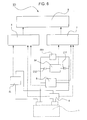
- Fig. 8 illustrates a state detection method in a fifth embodiment of the present invention, for the storage device 1; the drawing is a block diagram of a measurement system 105 that measures the states (SOH, SOC) of the storage device 1.
- the state detection method, in the fifth embodiment, for the storage device 1 differs from the first embodiment in that a converting unit 3 is provided that converts a pulse given to the storage device 1 to a frequency component.
- a converting unit 3 is provided that converts a pulse given to the storage device 1 to a frequency component.
- the state detection method, in the fifth embodiment of the present invention, for the storage device 1 is a measurement system in which the measurement system 105, illustrated in Fig. 8 , that measures the states (SOH, SOC) of the storage device 1 is used. As illustrated in Fig.
- the measurement system 105 includes the signal source 5L used to supply an alternating-current signal with a first frequency or a direct-current signal to the storage device 1, the converting unit 3 that converts the waveforms of the voltage and current of the storage device 1 to frequency components when a pulse signal is given to the storage device 1 in response to a trigger TR such as switch-on, the current detecting unit 4 and voltage detecting unit 6 that detect a current and a voltage observed by the storage device 1 when the pulse is applied, the internal-temperature calculating unit 7 that calculates an internal temperature by using an entered signal with a second frequency and the detected current and voltage, the state calculating unit 8 that calculates the state of the storage device 1 by using an entered signal with the first frequency and the detected current and voltage, and the state detecting unit 9 that corrects the state calculated by the state calculating unit 8 by using the internal temperature calculated by the internal-temperature calculating unit 7 and then performs inference.
- the signal source 5L used to supply an alternating-current signal with a first frequency or a direct-current
- the above trigger TR is switch-on at the start of the engine, a time at which charging is performed when a regenerative brake is applied, a time at which the storage device 1 is rapidly charged, or the like.
- a pulse signal generated at this time is given to the storage device 1.
- a transient response signal induced in the storage device 1 by this pulse signal can be converted to a frequency component by using a Fourier transform.
- the second frequency that is hard for ions in the storage device 1 to follow is selected from frequency components included in the pulse signal, the internal impedance of the storage device 1 at this second frequency is calculated, and the calculated value is used as the measured value, temperature error due to a difference in the behavior of the ions is not measured.
- the internal temperature of the storage device 1 can be accurately measured.
- the initial SOH or initial SOC of the storage device 1 is calculated from the internal resistance of the storage device 1 at the first frequency, after which the SOH or SOC is inferred by the accurate internal temperature described above to correct the initial SOH or initial SOC. Therefore, an accurate SOH or SOC can be obtained.
- the initial SOH or initial SOC of the storage device 1 is calculated from the measured value of the internal resistance of the storage device 1 at a first frequency
- the internal temperature is calculated from the measured impedance value of the internal impedance of the storage device 1
- the SOH or SOC is inferred by using the calculated value of the internal temperature to correct the initial SOH or initial SOC, so an accurate SOH or SOC can be obtained because a correction based on the calculated internal temperature can be made.
- the internal impedance of the storage device 1 is measured by using a signal with a second frequency that is hard for ions in the electrolyte E1 in the storage device 1 to follow, the internal impedance can be measured in a state in which effects by the behavior of the ions are adequately reduced and the internal temperature of the storage device 1 can thereby be more accurately measured. Therefore, the initial SOH or initial SOC can be corrected according to the accurate internal temperature. Thus, the SOH or SOC of the storage device 1 can be accurately detected.
- the calculated value of an internal impedance at a second frequency that is hard for ions to follow is used as the measured value by using a Fourier transform from a transient response signal induced in the storage device 1 by a pulse signal given to the storage device 1, there is no need to provide an alternating-current signal source used to supply a signal with a high frequency to the storage device 1 and there is also no need to supply a signal with a high frequency to the storage device 1 anew.
- an alternating-current signal source used for measurement does not need to be prepared, so it is possible to reduce a cost to manufacture the storage device 1 that uses the state detection method, in the fifth embodiment of the present invention, for the storage device 1.
- the structure and method in the fifth embodiment of the present invention can be practiced by appropriately combining them with structures and methods in other embodiments. So far, in the fifth embodiment, a method of detecting the SOH and SOC of the storage device 1 by using the measurement system 105 has been described. However, the method is not limited to detecting the SOH and the SOC together; a method of detecting only the SOH or only the SOC is also included.
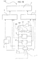
- Fig. 9 illustrates a state detection method, in a sixth embodiment of the present invention, for the storage device 1; the drawing is a block diagram of a measurement system 106 that measures the states (SOH, SOC) of the storage device 1.
- the state detection method, in the sixth embodiment, for the storage device 1 differs from the first embodiment in that low-pass filters 12a and 12b are used to remove high-frequency noise generated in a load FR4 and a charging circuit 11.
- the same reference characters will be assigned and detailed descriptions will be omitted.
- the state detection method, in the sixth embodiment of the present invention, for the storage device 1 is a measurement system in which the measurement system 106, illustrated in Fig. 9 , that measures the states (SOH, SOC) of the storage device 1 is used. As illustrated in Fig.
- the measurement system 106 includes the signal source 5L used to supply an alternating-current signal with a first frequency or a direct-current signal to the storage device 1, the alternating-current signal source 5H used to supply a signal with a second frequency to the storage device 1, the current detecting unit 4 and voltage detecting unit 6 that detect a current and a voltage observed by the storage device 1 when these signals are applied, the internal-temperature calculating unit 7 that calculates the internal temperature of the storage device 1 by using a signal with the second frequency, the signal being entered from the alternating-current signal source 5H, and the current and voltage that are detected by the current detecting unit 4 and voltage detecting unit 6, the state calculating unit 8 that calculates the state of the storage device 1 by using an entered signal with the first frequency and the detected current and voltage, and the state detecting unit 9 that corrects the state calculated by the state calculating unit 8 by using the internal temperature calculated by the internal-temperature calculating unit 7 and then performs inference.
- the signal source 5L used to supply an alternating-current signal with
- the load FR4 to which to supply electric power, and the charging circuit 11, which charges the storage device 1, are connected with a switch SWa intervening between them.
- the switch SWa By the switch SWa, the storage device 1 and load FR4 are connected when the storage device 1 is discharged and the storage device 1 and charging circuit 11 are connected when the storage device 1 is charged.
- the load FR4 is a power converting apparatus such as an inverter that converts direct-current power of the storage device 1 to alternating-current power.
- a capacitor C14 used to suppress a ripple current is connected in parallel to the load FR4.
- the low-pass filter 12a is connected in series with the load FR4.
- the low-pass filter 12a which is disposed between the load FR4 and the storage device 1, removes high-frequency components (noise) in a signal generated in the load FR4.
- the low-pass filter 12a is disposed closer to the same side as the storage device 1 than the capacitor C14, which suppresses a ripple current.
- the low-pass filter 12b is connected in series with the charging circuit 11.
- the low-pass filter 12b which is disposed between the charging circuit 11 and the storage device 1, removes high-frequency components (noise) in a signal generated in the charging circuit 11.
- the second frequency of a signal used to measure an internal temperature is higher than the pass bands of the low-pass filters 12a and 12b. That is, the high-frequency components (noise) in signals generated in the load FR4 and charging circuit 11 are removed by the low-pass filters 12a and 12b, so these high-frequency components do not affect detection precision of the current detecting unit 4 and voltage detecting unit 6. Therefore, it is possible to prevent precision in internal temperature measurement from being lowered by the signals from the load FR4 and charging circuit 11.
- the initial SOH or initial SOC of the storage device 1 is calculated from the internal resistance of the storage device 1 at the first frequency, after which the SOH or SOC is inferred by using the accurate internal temperature described above to correct the initial SOH or initial SOC. Therefore, an accurate SOH or SOC can be obtained.
- the initial SOH or initial SOC of the storage device 1 is calculated from the measured value of the internal resistance of the storage device 1 at a first frequency
- the internal temperature is calculated from the measured impedance value of the internal impedance of the storage device 1
- the SOH or SOC is inferred by using the calculated value of the internal temperature to correct the initial SOH or initial SOC, so an accurate SOH or SOC can be obtained because a correction based on the calculated internal temperature can be made.
- the internal impedance of the storage device 1 is measured by using a signal with a second frequency at which the internal impedance of the storage device 1 is increased as a temperature is raised, the resistance, depending only on the temperature, of the storage device 1 in electronic conduction can be measured and the internal temperature of the storage device 1 can thereby be more accurately measured. Therefore, the initial SOH or initial SOC can be corrected according to the accurate internal temperature. Thus, the SOH or SOC of the storage device 1 can be accurately detected.
- the low-pass filter 12b is provided between the storage device 1 and the charging circuit 11 connected to the storage device 1, noise at the second frequency, the noise being included in an internal temperature measurement signal generated in the charging circuit 11, can be removed. Therefore, it is possible to prevent precision in internal temperature measurement from being lowered by a signal from the charging circuit 11 and to maintain high precision in temperature calculation. Accordingly, the initial SOH and initial SOC can be corrected according to the more accurate internal temperature, and the SOH and SOC of the storage device 1 can thereby be even more accurately detected.
- the low-pass filter 12a is provided between the storage device 1 and the load FR4 connected to the storage device 1, noise at the second frequency, the noise being included in an internal temperature measurement signal generated in the load FR4, can be removed. Therefore, it is possible to prevent precision in internal temperature measurement from being lowered by a signal from the load FR4 and to maintain high precision in temperature calculation. Accordingly, the initial SOH and initial SOC can be corrected according to the more accurate internal temperature, and the SOH and SOC of the storage device 1 can thereby be even more accurately detected.
- the structure and method in the sixth embodiment of the present invention can be practiced by appropriately combining them with structures and methods in other embodiments. So far, in the sixth embodiment, a method of detecting the SOH and SOC of the storage device 1 by using the measurement system 106 has been described. However, the method is not limited to detecting the SOH and the SOC together; a method of detecting only the SOH or only the SOC is also included.
- Fig. 10 illustrates a state detection method, in a seventh embodiment of the present invention, for the storage device 1; the drawing is a block diagram of a measurement system 107 that measures the states (SOH, SOC) of the storage device 1.
- the state detection method, in the seventh embodiment, for the storage device 1 differs from the first embodiment in that the internal impedance of the storage device 1 is measured by using a high-frequency signal generated in a load FR5.
- the same reference characters will be assigned and detailed descriptions will be omitted.
- the state detection method, in the seventh embodiment of the present invention, for the storage device 1 is a measurement system in which the measurement system 107, illustrated in Fig. 10 , that measures the states (SOH, SOC) of the storage device 1 is used.
- the load FR5 to which electric power is supplied from the storage device 1, is connected, as illustrated in Fig. 10 .
- the power converter 17 (load FR5) performs a switching operation by using a signal with a high frequency (second frequency) suitable for the measurement of the internal temperature of the storage device 1; the power converter 17 (load FR5) is structured so that the signal with the second frequency, the signal being involved in the switching operation, is used in the measurement.
- the measurement system 107 also includes the signal source 5L used to supply an alternating-current signal with a first frequency or a direct-current signal to the storage device 1, the current detecting unit 4 and voltage detecting unit 6 that detect a current and a voltage observed by the storage device 1 when a signal from the switching power supply of the power converter 17 (load FR5) is applied, the internal-temperature calculating unit 7 that calculates the internal temperature of the storage device 1 by using a signal with the second frequency, the signal being entered from the power converter 17 (load FR5), and the current and voltage that are detected by the current detecting unit 4 and voltage detecting unit 6, the state calculating unit 8 that calculates the state of the storage device 1 by using an entered signal with the first frequency and the detected current and voltage, and the state detecting unit 9 that corrects the state calculated by the state calculating unit 8 by using the internal temperature calculated by the internal-temperature calculating unit 7 and then performs inference.
- the signal source 5L used to supply an alternating-current signal with a first frequency or a direct-
- the initial SOH or initial SOC of the storage device 1 is calculated from the measured value of the internal resistance of the storage device 1 at a first frequency
- the internal temperature is calculated from the measured impedance value of the internal impedance of the storage device 1
- the SOH or SOC is inferred by using the calculated value of the internal temperature to correct the initial SOH or initial SOC, so an accurate SOH or SOC can be obtained because a correction based on the calculated internal temperature can be made.
- the internal impedance of the storage device 1 is measured by using a signal with a second frequency at which the internal impedance of the storage device 1 is increased as a temperature is raised, the resistance, depending only on the temperature, of the storage device 1 in electronic conduction can be measured and the internal temperature of the storage device 1 can thereby be more accurately measured. Therefore, the initial SOH or initial SOC can be corrected according to the accurate internal temperature. Thus, the SOH or SOC of the storage device 1 can be accurately detected.
- the internal impedance of the storage device 1 is measured by using a signal, with the second frequency, that is generated from the switching power supply of the power converter 17 (load FR5) connected to the storage device 1, there is no need to provide the alternating-current signal source 5H, which has been used in the measurement systems 101, 103, and 106 in the first embodiment. Therefore, it is possible to maintain high precision in temperature measurement and to reduce a cost required for the measurement system 107 used in the state detection method, in the seventh embodiment of the present invention, for the storage device 1.
- the structure and method in the seventh embodiment of the present invention can be practiced by appropriately combining them with structures and methods in other embodiments. So far, in the seventh embodiment, a method of detecting the SOH and SOC of the storage device 1 by using the measurement system 107 has been described. However, the method is not limited to detecting the SOH and the SOC together; a method of detecting only the SOH or only the SOC is also included.
- Fig. 11 illustrates a state detection method in an eighth embodiment of the present invention for the storage device 1; the drawing is a block diagram of a measurement system 108 that measures the states (SOH, SOC) of the storage device 1.
- Fig. 12 illustrates the state detection method in the eighth embodiment of the present invention, for the storage device 1; the drawing is a graph representing a state in which a current phase and a voltage phase match.
- the state detection method, in the eighth embodiment, for the storage device 1 differs from the first embodiment in that a phase compensating circuit 14 is used to match the current phase and voltage phase at a second frequency.
- the same reference characters will be assigned and detailed descriptions will be omitted.
- the state detection method, in the eighth embodiment of the present invention, for the storage device 1 is a measurement system in which the measurement system 108, illustrated in Fig. 11 , that measures the states (SOH, SOC) of the storage device 1 is used. As illustrated in Fig.
- the measurement system 108 includes the signal source 5L used to supply an alternating-current signal with a first frequency or a direct-current signal to the storage device 1, the alternating-current signal source 5H used to supply a signal with the second frequency to the storage device 1, the current detecting unit 4 and voltage detecting unit 6 that detect a current and a voltage observed by the storage device 1 when the signal from the alternating-current signal source 5H is applied, the internal-temperature calculating unit 7 that calculates the internal temperature of the storage device 1 by using an entered signal with the second frequency, and the detected current and voltage, the state calculating unit 8 that calculates the state of the storage device 1 by using an entered signal with the first frequency and the detected current and voltage, and the state detecting unit 9 that corrects the state calculated by the state calculating unit 8 by using the internal temperature calculated by the internal-temperature calculating unit 7 and then performs inference.
- the phase compensating circuit 14 which is used to match a current phase and a voltage phase generated in the signal with the second frequency, the signal being from the alternating-current signal source 5H, is connected to the storage device 1.
- the current detecting unit 4 and voltage detecting unit 6 with high time resolution are needed to measure a phase difference between a current and a voltage.
- the phase of a current and the phase of a voltage at the second frequency are matched by the phase compensating circuit 14, so even if the time resolution of the current detecting unit 4 and voltage detecting unit 6 is not high, the resistance component (real part) of the internal impedance of the storage device 1 can be precisely measured.
- the internal impedance of the storage device 1 can be measured in real time.
- phase compensating circuit 14 it is preferable for the phase compensating circuit 14 to be provided so that it forms, together with the storage device 1, a series resonant circuit that resonates with the second frequency.
- a capacitive reactance is provided that series resonates at the second frequency due to the inductive reactance of the storage device 1 at the second frequency.
- the imaginary part of the impedance can be made to be 0 at the resonance frequency, so if a signal with this resonance frequency (equivalent to the second frequency) is used, only the resistive component of the internal impedance of the storage device 1 can be detected.
- the inductance component of the impedance of the storage device 1 is dominant, that is, the reactance component is inductive, so it is preferable for the phase compensating circuit 14 to be formed so as to include a capacitor (not illustrated).
- the phase compensating circuit 14 can match the phase of a current and the phase of a voltage with a simple structure.
- Fig. 12 is a graph that indicates a state in which the phase of a current and the phase of voltage at the second frequency are matched by the resonant circuit formed with the storage device 1 and phase compensating circuit 14.
- FIG. 12 illustrates an example in which the alternating-current signal source 5H was used as a constant-current source to generate an alternating current with a maximum value and a minimum value of ⁇ 20 mA at a frequency of 300 kHz. As illustrated in Fig. 12 , it is well seen that the phase of the current (indicated by the broken lines) and the phase of the voltage (indicated by the solid lines) are matched by using the phase compensating circuit 14.
- the initial SOH of the storage device 1 is calculated from the measured value of the internal resistance of the storage device 1 at a first frequency
- the internal temperature is calculated from the measured impedance value of the internal impedance of the storage device 1
- the SOH is inferred by using the calculated value of the internal temperature to correct the initial SOH, so an accurate SOH can be obtained because a correction based on the calculated internal temperature can be made.
- the internal impedance of the storage device 1 is measured by using a signal with a second frequency at which the inductance component of the internal impedance of the storage device 1 becomes more dominant than the inductance component, that is, the reactance component becomes inductive, the internal impedance can be measured in a state in which effects by the behavior of ions are adequately reduced and the internal temperature of the storage device 1 can thereby be more accurately measured. Therefore, the initial SOH can be corrected according to the accurate internal temperature. Thus, the SOH of the storage device 1 can be accurately detected.
- phase compensating circuit 14 When the phase of a current and the phase of a voltage are matched by the phase compensating circuit 14 connected to the storage device 1, even if the performance of a detecting apparatus is not high, the internal impedance of the storage device 1 can be precisely measured. Therefore, it is possible to maintain high precision in temperature measurement and to reduce a cost required for the measurement system 108.
- the inductive reactor in the storage device 1 and the capacitive reactor in the phase compensating circuit 14 form a resonant circuit that resonates with the second frequency
- the imaginary part of the impedance can be made to be 0 at this resonance frequency of the resonant circuit. Therefore, only the resistive component of the internal impedance of the storage device 1 can be detected by a signal with the resonant frequency. Accordingly, the initial SOH and initial SOC can be corrected according to a more accurate internal temperature, and the SOH and SOC of the storage device 1 can thereby be even more accurately detected.
- the phase compensating circuit 14 is formed so as to include a capacitor, the phase compensating circuit 14 can match the phase of a current and the phase of a voltage with a simple structure. Thus, it is possible to manufacture the phase compensating circuit 14 at a low cost and thereby to reduce a cost required for the measurement system 108 used in the state detection method, in the eighth embodiment of the present invention, for the storage device 1.
- the structure and method in the eighth embodiment of the present invention can be practiced by appropriately combining them with structures and methods in other embodiments. So far, in the eighth embodiment, a method of detecting the SOH and SOC of the storage device 1 by using the measurement system 108 has been described. However, the method is not limited to detecting the SOH and the SOC together; a method of detecting only the SOH or only the SOC is also included.
- the internal impedance of the storage device 1 is measured under the condition that in the measurement system 106 illustrated in Fig. 9 , for example, the impedance of the storage device 1 is lower than the impedance, as viewed from the storage device 1, of the charging circuit 11.
- the internal impedance of the storage device 1 is also measured under the condition that in the measurement system 107 illustrated in Fig. 10 , for example, the impedance of the storage device 1 is lower than the impedance, as viewed from the storage device 1, of the load.
- the impedance of the storage device 1 is denoted Z1
- the impedance, as viewed from the storage device 1, of the load is denoted Z2
- the load, as viewed from the storage device 1, of the charging circuit 11 is denoted Z3, it is adapted that at the second frequency used in measurement, Z1 ⁇ Z2 or Z1 ⁇ Z3 is satisfied.
- effects by structures other than of the storage device 1 are small, so precision in internal impedance measurement can be increased. As a result, high measurement precision can be achieved.
- the internal impedance of the storage device 1 is measured by using a signal with the second frequency at which the impedance of the storage device 1 is lower than the impedance of the charging circuit 11, effects by the charging circuit 11 are reduced in internal impedance measurement. Therefore, it is possible to increase precision in internal impedance measurement and thereby to calculate a temperature highly preciously. Accordingly, the initial SOH and initial SOC can be corrected according to the more accurate internal temperature, and the SOH and SOC of the storage device 1 can thereby be even more accurately detected.
- the internal impedance of the storage device 1 is measured by using a signal with the second frequency at which the impedance of the storage device 1 is lower than the impedance of the load, effects by the load are reduced in internal impedance measurement. Therefore, it is possible to increase precision in internal impedance measurement and thereby to calculate a temperature highly preciously. Accordingly, the initial SOH and initial SOC can be corrected according to the more accurate internal temperature, and the SOH and SOC of the storage device 1 can thereby be even more accurately detected.
- the structure and method in the ninth embodiment of the present invention can be practiced by appropriately combining them with structures and methods in other embodiments. So far, in the ninth embodiment, a method of detecting the SOH and SOC of the storage device 1 by using a measurement system has been described. However, the method is not limited to detecting the SOH and the SOC together; a method of detecting only the SOH or only the SOC is also included.
- the present invention is not limited to the above embodiments.
- the present invention can also be practiced by being modified, for example, as described below. Modified embodiments are also included in the technical range of the present invention.
- Fig. 13 illustrates variation 1 of the device state detection method, in the first embodiment of the present invention, for the storage device 1; the drawing is a block diagram of a measurement system C101 that measures the internal temperature of the storage device 1.
- a measurement system may be the measurement system C101, in which a switch SW1, a switch SW2, and a dummy load DR are added to the measurement portion in the measurement system 101 in the first embodiment described above, as illustrated in Fig. 13 .
- the present invention is not limited to the above embodiments.
- the present invention can be appropriately modified without departing from the intended scope of the present invention.
Abstract
Description
- The present invention relates to a method of detecting states of a storage device, and more particularly to a storage device state detection method of detecting the state of health and state of charge of a storage device.
- Storage devices such as lithium-ion secondary batteries and electric double-layer capacitors are used in various applications; for example, they are widely used in battery packs in mobile telephones, batteries in PCs, and batteries in automobiles. In this case, it is very important to detect states of a storage device such as, for example, the state of health (called SOH; State of Health) and the state of charge (called SOC; State of Charge). Particularly as for automobiles, detection of states of a storage device in an energy-saving automobile, which performs idle reduction, a hybrid automobile, an electric car is closely related to the running of the automobile, attracting attention as being very important.
- A generally well-known method of detecting states of a storage device is to measure the voltage, current, and temperature of the storage device and calculate the state of health (SOH) and state of charge (SOC) of the storage device. Of these, the temperature of the storage device is a very important measurement parameter because the temperature of the storage device gives a large effect when the state of the storage device is detected.
- As related art of a method of measuring the temperature of a storage device, a method of directly measuring the temperature with a temperature detecting element attached or connected to the storage device, as described in
PTL 1, is generally known. InPTL 1, a zener diode is used as the temperature detecting element; the zener diode is connected to the positive terminal of a storage device so that a temperature transferred from the positive terminal of the storage device can be accurately measured. In PTL 1 (conventional example 1), however, there has been the problem that a large difference may occur between a temperature in the storage device and a temperature at a temperature detection point (in conventional example 1, the positive terminal of the storage device) of the temperature detecting element, in which case an accurate temperature of the storage device cannot be grasped. - By contrast, a device (PTL 2) that detects the temperature of a storage device by using a temperature detecting element such as a thermocouple obtains the internal impedance of the storage device and decides the state of health (SOH) of the storage device and a device (PTL 3) that obtains the internal impedance of the storage device without using a temperature detecting element and determines an internal temperature.
- A device in PTL 2 (conventional example 2) is formed with a temperature adjusting means for adjusting the temperature of the storage device, an impedance calculating means for calculating the internal impedance of the storage device, and a deterioration deciding means for deciding the state of health (SOH) of the storage device according to the calculated internal impedance. The state of health (SOH) can be decided with reference to an internal impedance map that has been preset in correspondence to the temperature of the storage device and the voltage of the storage device according to the voltage of the storage device and the temperature of the storage device and to a calculated value of the internal impedance in a state in which the storage device has been adjusted to a temperature within a prescribed range by the temperature adjusting means when the storage device is charged or discharged with an alternating current at a prescribed frequency (at least 10 Hz and at most 1 kHz).
- The device, in PTL 3 (conventional example 3), that determine an internal temperature is formed with an electric excitation circuit used to apply time-varying electric excitation to a storage device, a response detecting circuit used to detect an electric response that varies with time as a result of the time-varying electric excitation, and a calculation circuit used to determine an internal temperature by using a voltage and current signal derived from entered excitation and an entered response signal. Time-varying electric excitation is provided at different frequencies (in an embodiment, 5 Hz, 70 Hz, and 1 kHz), a measured impedance is assigned to an assumed equivalent circuit, and the internal temperature of the storage device is calculated from a particular element value of the equivalent circuit.
-
- PTL 1: Japanese Unexamined Patent Application Publication No.
6-260215 - PTL 2: Japanese Unexamined Patent Application Publication No.
2010-67502 - PTL 3: Japanese Unexamined Patent Application Publication (Translation of
PCT Application) No. 2003-508759 - PTL 4: Japanese Unexamined Patent Application Publication No.
2012-220199 - In conventional example 2, however, the internal impedance is measured at a low frequency (in conventional example 2, at least 10 Hz and at most 1 kHz), at which the internal impedance is affected by the behavior of ions in an electrolyte in the storage device. To measure the internal impedance accurately, therefore, a measurement is made in a state in which the storage device has been adjusted to a temperature within a prescribed range by the temperature adjusting means so that the internal impedance is not affected by a temperature. In this method, there is a time difference between a temperature around the storage device that has been adjusted by the temperature adjusting means and the true internal temperature of the storage device in temperature variations during charging and discharging. Therefore, an accurate internal temperature of the storage device could not be obtained at the time of state detection. Thus, there has been the problem that a correction for the effects by the internal temperature is not accurately made and error is thereby caused in a decision of the state of health (SOH).
- In conventional example 3, it is preferable to use a frequency with few variations in the state of charge (SOC) in measurement. As in conventional example 2, however, the internal impedance is measured at a low frequency (in conventional example 3, 5 Hz, 70 Hz, and 1 kHz) at which the internal impedance is affected by the behavior of ions in an electrolyte in the storage device. Depending on the state of health (SOH) and state of charge (SOC) of the storage device, therefore, the measured value of the internal impedance varies, so the accurate internal temperature of the storage device could not be obtained. Therefore, even if an internal temperature calculating method as in conventional example 3 is used, there has been the problem that the state of health (SOH) and state of charge (SOC) of the storage device cannot be accurately detected.
- The present invention solves the above problems. An object of the present invention is to provide a storage device state detection method of accurately detecting the state of health (SOH) and state of charge (SOC) of a storage device.
- In a storage device state detection method in which the SOH of the storage device is inferred from the internal impedance of the storage device, the storage device state detection method of the present invention is characterized in that: the internal resistance of the storage device is measured by using a signal with a first frequency at which the internal impedance of the storage device is reduced as a temperature is raised, and the initial SOH of the storage device is calculated from the measured value of the internal resistance; the internal impedance of the storage device is measured by using a signal with a second frequency at which the internal impedance of the storage device is increased as a temperature is raised, and the internal temperature of the storage device is calculated from the measured impedance value of the internal impedance; and the SOH is inferred by using the calculated value of the internal temperature to correct the initial SOH.
- Accordingly, in the storage device state detection method of the present invention, the initial SOH of the storage device is calculated from the measured value of the internal resistance of the storage device at a first frequency, the internal temperature is calculated from the measured impedance value of the internal impedance of the storage device, and the SOH is inferred by using the calculated value of the internal temperature to correct the initial SOH, so an accurate SOH can be obtained because a correction based on the calculated internal temperature can be made. Particularly, since the internal impedance of the storage device is measured by using a signal with a second frequency at which the internal impedance of the storage device is increased as a temperature is raised, the resistance, depending only on the temperature, of the storage device in electronic conduction can be measured and the internal temperature of the storage device can thereby be more accurately measured. Therefore, the initial SOH can be corrected according to the accurate internal temperature. Thus, the SOH of the storage device can be accurately detected.
- In a storage device state detection method in which the SOH of the storage device is inferred from the internal impedance of the storage device, the storage device state detection method of the present invention is characterized in that: the internal resistance of the storage device is measured by using a signal with a first frequency at which the capacitance component of the internal impedance of the storage device becomes more dominant than the inductance component, and the initial SOH of the storage device is calculated from the measured value of the internal resistance; the internal impedance of the storage device is measured by using a signal with a second frequency at which the inductance component of the internal impedance of the storage device becomes more dominant than the capacitance component, and the internal temperature of the storage device is calculated from the measured impedance value of the internal impedance; and the SOH is inferred by using the calculated value of the internal temperature to correct the initial SOH.
- Accordingly, the initial SOH of the storage device is calculated from the measured value of the internal resistance of the storage device at a first frequency, the internal temperature is calculated from the measured impedance value of the internal impedance of the storage device, and the SOH is inferred by using the calculated value of the internal temperature to correct the initial SOH, so an accurate SOH can be obtained because a correction based on the calculated internal temperature can be made. Particularly, since the internal impedance of the storage device is measured by using a signal with a second frequency at which the inductance component of the internal impedance of the storage device becomes more dominant than the capacitance component, that is, the reactance component becomes inductive, the internal impedance can be measured in a state in which effects by the behavior of ions are adequately reduced and the internal temperature of the storage device can thereby be more accurately measured. Therefore, the initial SOH can be corrected according to the accurate internal temperature. Thus, the SOH of the storage device can be accurately detected.
- In a storage device state detection method in which the SOH of the storage device is inferred from the internal impedance of the storage device, the storage device state detection method of the present invention is characterized in that: the internal resistance of the storage device is measured by using a signal with a first frequency that ions in the storage device can follow, and the initial SOH of the storage device is calculated from the measured value of the internal resistance; the internal impedance of the storage device is measured by using a signal with a second frequency that is hard for the ions in the storage device to follow, and the internal temperature of the storage device is calculated from the measured impedance value of the internal impedance; and the SOH is inferred by using the calculated value of the internal temperature to correct the initial SOH.
- Accordingly, the initial SOH of the storage device is calculated from the measured value of the internal resistance of the storage device at a first frequency, the internal temperature is calculated from the measured impedance value of the internal impedance of the storage device, and the SOH is inferred by using the calculated value of the internal temperature to correct the initial SOH, so an accurate SOH can be obtained because a correction based on the calculated internal temperature can be made. Particularly, since the internal impedance of the storage device is measured by using a signal with a second frequency that is hard for ions in an electrolyte in the storage device to follow, the internal impedance can be measured in a state in which effects by the behavior of the ions are adequately reduced and the internal temperature of the storage device can thereby be more accurately measured. Therefore, the initial SOH can be corrected according to the accurate internal temperature. Thus, the SOH of the storage device can be accurately detected.
- In a storage device state detection method in which the SOH of the storage device is inferred from the internal impedance of the storage device, the storage device state detection method of the present invention is characterized in that: the internal resistance of the storage device is measured by using a signal with a first frequency of 1 kHz or lower, and the initial SOH of the storage device is calculated from the measured value of the internal resistance; the internal impedance of the storage device is measured by using a signal with a second frequency of 10 kHz or higher, and the internal temperature of the storage device is calculated from the measured impedance value of the internal impedance; and the SOH is inferred by using the calculated value of the internal temperature to correct the initial SOH.
- Accordingly, the initial SOH of the storage device is calculated from the measured value of the internal resistance of the storage device at a first frequency, the internal temperature is calculated from the measured impedance value of the internal impedance of the storage device, and the SOH is inferred by using the calculated value of the internal temperature to correct the initial SOH, so an accurate SOH can be obtained because a correction based on the calculated internal temperature can be made. Particularly, since the internal impedance of the storage device is measured by using a signal with a second frequency of 10 kHz or higher, ions in the electrolyte do not follow the second frequency, the internal impedance can be measured in a state in which effects by the behavior of ions are adequately reduced. Therefore, the internal temperature of the storage device can be more accurately measured, and the initial SOH can thereby be corrected according to the accurate internal temperature. Thus, the SOH of the storage device can be accurately detected.
- The storage device state detection method of the present invention is characterized in that the SOC at the time of measuring the internal resistance is substantially the same at each time.
- Accordingly, since the SOC at the time of measuring the internal resistance is substantially the same at each time, effects on the internal resistance by a difference in the SOC can be reduced. Therefore, a more accurate initial SOH can be calculated, and the SOH of the storage device can thereby be more accurately detected.
- The storage device state detection method of the present invention is characterized in that the internal resistance is measured within a prescribed time after the storage device has been fully charged.
- Accordingly, since the internal resistance is measured within a prescribed time after the storage device has been fully charged, when the SOC is always placed under a constant condition, effects on the internal resistance by a difference in the SOC can be reliably reduced. Therefore, an even more accurate initial SOH can be calculated, and the SOH of the storage device can thereby be even more accurately detected.
- In a storage device state detection method in which the SOC of the storage device is inferred from the internal impedance of the storage device, the storage device state detection method of the present invention is characterized in that: the internal resistance of the storage device is measured by using a signal with a first frequency at which the internal impedance of the storage device is reduced as a temperature is raised, and the initial SOC of the storage device is calculated from the measured value of the internal resistance; the internal impedance of the storage device is measured by using a signal with a second frequency at which the internal impedance of the storage device is increased as a temperature is raised, and the internal temperature of the storage device is calculated from the measured impedance value of the internal impedance; and the SOC is inferred by using the calculated value of the internal temperature to correct the initial SOC.
- Accordingly, the initial SOC of the storage device is calculated from the measured value of the internal resistance of the storage device at a first frequency, the internal temperature is calculated from the measured impedance value of the internal impedance of the storage device, and the SOC is inferred by using the calculated value of the internal temperature to correct the initial SOC, so an accurate SOC can be obtained because a correction based on the calculated internal temperature can be made. Particularly, since the internal impedance of the storage device is measured by using a signal with a second frequency at which the internal impedance of the storage device is increased as a temperature is raised, the resistance, depending only on the temperature, of the storage device in electronic conduction can be measured and the internal temperature of the storage device can thereby be more accurately measured. Therefore, the initial SOC can be corrected according to the accurate internal temperature. Thus, the SOC of the storage device can be accurately detected.
- In a storage device state detection method in which the SOC of the storage device is inferred from the internal impedance of the storage device, the storage device state detection method of the present invention is characterized in that: the internal resistance of the storage device is measured by using a signal with a first frequency at which the capacitance component of the internal impedance of the storage device becomes more dominant than the inductance component, and the initial SOC of the storage device is calculated from the measured value of the internal resistance; the internal impedance of the storage device is measured by using a signal with a second frequency at which the inductance component of the internal impedance of the storage device becomes more dominant than the capacitance component, and the internal temperature of the storage device is calculated from the measured impedance value of the internal impedance; and the SOC is inferred by using the calculated value of the internal temperature to correct the initial SOC.
- Accordingly, the initial SOC of the storage device is calculated from the measured value of the internal resistance of the storage device at a first frequency, the internal temperature is calculated from the measured impedance value of the internal impedance of the storage device, and the SOC is inferred by using the calculated value of the internal temperature to correct the initial SOC, so an accurate SOC can be obtained because a correction based on the calculated internal temperature can be made. Particularly, since the internal impedance of the storage device is measured by using a signal with a second frequency at which the inductance component of the internal impedance of the storage device becomes more dominant than the capacitance component, that is, the reactance component becomes inductive, the internal impedance can be measured in a state in which effects by the behavior of ions are adequately reduced and the internal temperature of the storage device can thereby be more accurately measured. Therefore, the initial SOC can be corrected according to the accurate internal temperature. Thus, the SOC of the storage device can be accurately detected.
- In a storage device state detection method in which the SOC of the storage device is inferred from the internal impedance of the storage device, the storage device state detection method of the present invention is characterized in that: the internal resistance of the storage device is measured by using a signal with a first frequency that ions in the storage device can follow, and the initial SOC of the storage device is calculated from the measured value of the internal resistance; the internal impedance of the storage device is measured by using a signal with a second frequency that is hard for the ions in the storage device to follow, and the internal temperature of the storage device is calculated from the measured impedance value of the internal impedance; and the SOC is inferred by using the calculated value of the internal temperature to correct the initial SOC.
- Accordingly, the initial SOC of the storage device is calculated from the measured value of the internal resistance of the storage device at a first frequency, the internal temperature is calculated from the measured impedance value of the internal impedance of the storage device, and the SOC is inferred by using the calculated value of the internal temperature to correct the initial SOC, so an accurate SOC can be obtained because a correction based on the calculated internal temperature can be made. Particularly, since the internal impedance of the storage device is measured by using a signal with a second frequency that is hard for ions in an electrolyte in the storage device to follow, the internal impedance can be measured in a state in which effects by the behavior of the ions are adequately reduced and the internal temperature of the storage device can thereby be more accurately measured. Therefore, the initial SOC can be corrected according to the accurate internal temperature. Thus, the SOC of the storage device can be accurately detected.
- In a storage device state detection method in which the SOC of the storage device is inferred from the internal impedance of the storage device, the storage device state detection method of the present invention is characterized in that: the internal resistance of the storage device is measured by using a signal with a first frequency of 1 kHz or lower, and the initial SOC of the storage device is calculated from the measured value of the internal resistance; the internal impedance of the storage device is measured by using a signal with a second frequency of 10 kHz or higher, and the internal temperature of the storage device is calculated from the measured impedance value of the internal impedance; and the SOC is inferred by using the calculated value of the internal temperature to correct the initial SOC.
- Accordingly, the initial SOC of the storage device is calculated from the measured value of the internal resistance of the storage device at a first frequency, the internal temperature is calculated from the measured impedance value of the internal impedance of the storage device, and the SOC is inferred by using the calculated value of the internal temperature to correct the initial SOC, so an accurate SOC can be obtained because a correction based on the calculated internal temperature can be made. Particularly, since the internal impedance of the storage device is measured by using a signal with a second frequency of 10 kHz or higher, ions in the electrolyte do not follow the second frequency, the internal impedance can be measured in a state in which effects by the behavior of ions are adequately reduced. Therefore, the internal temperature of the storage device can be more accurately measured, and the initial SOC can thereby be corrected according to the accurate internal temperature. Thus, the SOC of the storage device can be accurately detected.
- The storage device state detection method of the present invention is characterized in that the internal resistance is measured before and after a large change of a current, and the internal resistance is obtained from before and after measured values that have been measured.
- Accordingly, since the internal resistance is obtained from measured values obtained before and after a large change of a current, when a measurement is made under a plurality of different conditions, the internal resistance can be more accurately calculated, and the initial SOH and initial SOC can thereby be more accurately calculated. Thus, the SOH and SOC of the storage device can be more accurately detected.
- The storage device state detection method of the present invention is characterized in that the storage device is mounted in an automobile and the automobile is stopping during the measurement of the internal resistance.
- Accordingly, since the internal resistance is measured while the automobile is stopping, it is possible to reduce effects by noise due to variations in a load to the storage device, noise from an inverter intended for motor control, and the like that are generated while the automobile is running. Since the noise has a frequency close to the band of the second frequency, therefore, the measurement of the internal temperature of the storage device is not affected. Accordingly, the initial SOH and initial SOC can be corrected according to a more accurate internal temperature, and the SOH and SOC of the storage device can thereby be even more accurately detected.
- The storage device state detection method of the present invention is characterized in that the storage device includes an anode collector, an electrolyte, a separator, and a cathode collector and the second frequency is a frequency at which the impedance of at least one of the anode collector, the electrolyte, the separator, and the cathode collector is measured as a resistance in electronic conduction.
- Accordingly, since the frequency of the signal is the second frequency at which the impedance of at least one of the anode collector, electrolyte, separator, and cathode collector is measured mainly as a resistance in electronic conduction rather than ion conduction, a difference in the behavior of ions due to a difference in the state of health (SOH) and the state of charge (SOC) of the storage device is not largely reflected in the measured value. Therefore, since a resistance in electron conduction, in other words, a resistance (R, real part) in an impedance is measured, a change in the internal impedance, depending only on the temperature, of the storage device can be measured and the internal temperature of the storage device can thereby be more accurately measured. Thus, the initial SOH and initial SOC can be corrected according to the more accurate internal temperature, and the SOH or SOC of the storage device can thereby be even more accurately detected.
- The storage device state detection method of the present invention is characterized in that a transient response signal induced by a pulse signal given to the storage is converted to a frequency component by a Fourier transform, the internal impedance at the second frequency is calculated, and the calculated value is used as the measured impedance value.
- Accordingly, since a Fourier transform from a transient response signal induced in the storage device by a pulse signal given to the storage device is used to take, as the measured value, the calculated value of an internal impedance at a second frequency that ions do not follow or that is 10 kHz or higher, there is no need to provide an alternating-current signal source used to supply a signal with a high frequency to the storage device and there is also no need to supply a signal with a high frequency to the storage device anew. Thus, an alternating-current signal source used for measurement does not need to be prepared, so it is possible to reduce a cost to manufacture the storage device that uses the storage device state detection method of the present invention.
- The storage device state detection method of the present invention is characterized in that the storage device is a secondary battery.
- Accordingly, since the storage device is a secondary storage device of the type in which charging and discharging are repeated, the state of health (SOH) and the state of charge (SOC) of the storage device vary at each time. In the storage device state detection method of the present invention, a difference in the behavior of ions due to a difference in the state of health (SOH) and the state of charge (SOC) of the storage device is not largely reflected in the measured value of the internal impedance, so even if the storage device of this type is used, the internal temperature of the storage device can be accurately measured. Furthermore, when a secondary battery is applied to a product with a large capacity, a large difference occurs between the internal temperature of the storage device and the surface temperature of the storage device due to heat that is internally generated by the storage device during charging and discharging with a large current. Even in this case, the internal temperature of the storage device can be accurately measured. Thus, the initial SOH and initial SOC can be corrected according to the even more accurate internal temperature, and the SOH and SOC of the storage device can thereby be increasingly even more accurately detected.
- The storage device state detection method of the present invention is characterized in that noise at the second frequency, the noise being in a signal generated in the charging circuit, is removed by a low-pass filter provided between the storage device and a charging circuit connected to the storage device.
- Accordingly, since a low-pass filter is provided between the storage device and a charging circuit connected to the storage device, noise at the second frequency, the noise being included in an internal temperature measurement signal generated in the charging circuit, can be removed. Therefore, it is possible to prevent precision in internal temperature measurement from being lowered by noise from the charging circuit and to maintain high precision in temperature calculation. Accordingly, the initial SOH and initial SOC can be corrected according to the accurate internal temperature, and the SOH and SOC of the storage device can thereby be even more accurately detected.
- The storage device state detection method of the present invention is characterized in that noise at the second frequency, the noise being in a signal generated in the charging circuit, is removed by a low-pass filter provided between the storage device and a load connected to the storage device.
- Accordingly, since a low-pass filter is provided between the storage device and a load connected to the storage device, noise at the second frequency, the noise being included in an internal temperature measurement signal generated in the load, can be removed. Therefore, it is possible to prevent precision in internal temperature measurement from being lowered by noise from the load and to maintain high precision in temperature calculation. Accordingly, the initial SOH and initial SOC can be corrected according to the more accurate internal temperature, and the SOH and SOC of the storage device can thereby be even more accurately detected.
- The storage device state detection method of the present invention is characterized in that the internal impedance of the storage device is measured by using a signal with the second frequency, the signal being generated from a switch power supply for a power converter connected to the storage device.
- Accordingly, since the internal impedance of the storage device is measured by using a signal generated from a power converter, there is no need to separately provide a signal source that generates an internal temperature measurement signal. Therefore, it is possible to maintain high precision in temperature measurement and to reduce a cost required for a measurement system used in the storage device state detection method of the present invention.
- The storage device state detection method of the present invention is characterized in that the internal impedance of the storage device is measured by using a signal with the second frequency at which the impedance of the storage device is lower than the impedance, as viewed from the storage device, of a charging circuit connected to the storage device.
- Accordingly, since the internal impedance of the storage device is measured by using a signal with the second frequency at which the impedance of the storage device is lower than the impedance of a charging circuit, effects by the charging circuit are reduced in internal impedance measurement. Therefore, it is possible to increase precision in internal impedance measurement and thereby to calculate a temperature highly preciously. Accordingly, the initial SOH and initial SOC can be corrected according to the more accurate internal temperature, and the SOH and SOC of the storage device can thereby be even more accurately detected.
- The storage device state detection method of the present invention is characterized in that the internal impedance of the storage device is measured by using a signal with the second frequency at which the impedance of the storage device is lower than the impedance, as viewed from the storage device, of a load connected to the storage device.
- Accordingly, since the internal impedance of the storage device is measured by using a signal with the second frequency at which the impedance of the storage device is lower than the impedance of a load, effects by the load are reduced in internal impedance measurement. Therefore, it is possible to increase precision in internal impedance measurement and thereby to calculate a temperature highly preciously. Accordingly, the initial SOH and initial SOC can be corrected according to the more accurate internal temperature, and the SOH and SOC of the storage device can thereby be even more accurately detected.
- The storage device state detection method of the present invention is characterized in that the phase of a current and the phase of a voltage due to a signal with the second frequency are matched by a phase compensating circuit connected to the storage device.
- Accordingly, since the phase of a current and the phase of a voltage are matched by a phase compensating circuit connected to the storage device, even if the performance of a detecting apparatus is not high, the internal impedance of the storage device can be precisely measured. Therefore, it is possible to maintain high precision in temperature measurement and to reduce a cost required for a measurement system used in the storage device state detection method of the present invention.
- The storage device state detection method of the present invention is characterized in that a resonant circuit that resonates with the second frequency is formed with the storage device and phase compensating circuit.
- Accordingly, since the storage device and phase compensating circuit form a resonant circuit that resonates with the second frequency, the imaginary part of the impedance can be made to be 0 at a resonance frequency. Therefore, only the resistive component of the internal impedance of the storage device can be detected. Accordingly, the initial SOH and initial SOC can be corrected according to a more accurate internal temperature, and the SOH and SOC of the storage device can thereby be even more accurately detected.
- The storage device state detection method of the present invention is characterized in that the phase compensating circuit includes a capacitor.
- Accordingly, since the phase compensating circuit is formed so as to include a capacitor, the phase compensating circuit with a simple structure can match the phase of a current and the phase of a voltage. Thus, it is possible to manufacture the phase compensating circuit at a low cost and thereby to reduce a cost required for a measurement system used in the storage device state detection method of the present invention.
- The storage device state detection method of the present invention can accurately detect the state of health (SOH) and the state of charge (SOC) of the storage device. Brief Description of Drawings
- [
Fig. 1] Fig. 1 illustrates a storage device state detection method in a first embodiment of the present invention; the drawing is a block diagram of a measurement system that measures the states (SOH, SOC) of the storage device. - [
Fig. 2] Fig. 2 illustrates the storage device state detection method in the first embodiment of the present invention, schematically illustrating the structure of a lithium-ion secondary battery. - [
Fig. 3] Fig. 3 illustrates the storage device state detection method in the first embodiment of the present invention; the drawing is an example of a graph representing the time dependence of the resistance of the storage device. - [
Fig. 4] Fig. 4 illustrates the storage device state detection method in the first embodiment of the present invention, schematically illustrating a state in which the storage device is mounted in an automobile. - [
Fig. 5] Fig. 5 illustrates a storage device state detection method in a second embodiment of the present invention; the drawing is an equivalent circuit diagram of a lithium secondary battery. - [
Fig. 6] Fig. 6 illustrates a storage device state detection method in a third embodiment of the present invention; the drawing is a block diagram of a measurement system that measures the states (SOH, SOC) of the storage device. - [
Fig. 7] Fig. 7 illustrates a storage device state detection method in a fourth embodiment of the present invention; the drawing is an example of a graph representing a relationship between the frequency of a signal supplied to the storage device and the real part (resistance) of an internal impedance. - [
Fig. 8] Fig. 8 illustrates a storage device state detection method in a fifth embodiment of the present invention; the drawing is a block diagram of another measurement system that measures the states (SOH, SOC) of the storage device. - [
Fig. 9] Fig. 9 illustrates a storage device state detection method in a sixth embodiment of the present invention; the drawing is a block diagram of a measurement system that measures the states (SOH, SOC) of the storage device. - [
Fig. 10] Fig. 10 illustrates a storage device state detection method in a seventh embodiment of the present invention; the drawing is a block diagram of a measurement system that measures the states (SOH, SOC) of the storage device. - [
Fig. 11] Fig. 11 illustrates a storage device state detection method in an eighth embodiment of the present invention; the drawing is a block diagram of a measurement system that measures the states (SOH, SOC) of the storage device. - [
Fig. 12] Fig. 12 illustrates the storage device state detection method in the eight embodiment of the present invention; the drawing is a graph representing a state in which a current phase and a voltage phase match. - [
Fig. 13] Fig. 13 illustratesvariation 1 of the storage device state detection method in the first embodiment of the present invention; the drawing is a block diagram of a measurement system that measures the internal temperature of the storage device. - [
Fig. 14] Fig. 14 is a graph representing a relationship between the frequency of a signal used in a measurement in the present invention and impedance variations with temperature. - Embodiments of the present invention will be described below in detail with reference to the attached drawings.
-
Fig. 1 illustrates a state detection method, in a first embodiment of the present invention, for astorage device 1; the drawing is a block diagram of ameasurement system 101 that measures the states (SOH, SOC) of thestorage device 1.Fig. 2 illustrates the state detection method, in the first embodiment of the present invention, for thestorage device 1, schematically illustrating the structure of a lithium-ion secondary battery L1.Fig. 3 illustrates the state detection method, in the first embodiment of the present invention, for thestorage device 1; the drawing is an example of a graph representing the time dependence of a resistance in thestorage device 1. - The state detection method, in the first embodiment of the present invention, for the
storage device 1 is a measurement system in which themeasurement system 101, illustrated inFig. 1 , that detects the states (SOH, SOC) of thestorage device 1 is used. As illustrated inFig. 1 , themeasurement system 101 includes an alternating-current signal source 5H used to supply a signal with a second frequency to thestorage device 1, asignal source 5L used to supply an alternating-current signal with a first frequency or a direct-current signal to thestorage device 1, a current detectingunit 4 and avoltage detecting unit 6 that detect a current and a voltage observed by thestorage device 1 when these signals are applied, an internal-temperature calculating unit 7 that calculates an internal temperature by using an entered signal with the second frequency and the detected current and voltage, astate calculating unit 8 that calculates the state of thestorage device 1 by using an entered signal with the first frequency and the detected current and voltage, and astate detecting unit 9 that corrects the state calculated by thestate calculating unit 8 by using the internal temperature calculated by the internal-temperature calculating unit 7 and then performs inference. The SOH (State Of Health) referred to here indicates the deterioration state (degree of deterioration) of a storage device; it represents, as a percentage, the amount of full charge in a used storage device with respect to the amount of full charge in a non-used (new) storage device. The SOC (State Of Charge) indicates the charged state of the storage'device; it represents a capacity remaining in the storage device as ampere-hours (Ah). - The
storage device 1 is, for example, a chargeable chemical battery such a lithium secondary battery. However, a device, such as an electric double-layer capacitor, that can use ions to store electric energy is also included. Generally, thestorage device 1 is structured mainly with an anode collector A1, a cathode collector C1, an electrolyte E1, and a separator S1. Besides the constituent elements described above, the lithium-ion secondary battery L1, for example, includes an anode active material A51, which is a material that stores electricity on the same side as the anode collector A1, a cathode active material C51, which is a material that stores electricity on the same side as the cathode collector C1, a conduction supporting agent D51, which is added so that electricity flows easily, a biding material, which is a binder, and the like, as illustrated inFig. 2 . As for the lithium-ion secondary battery L1, aluminum (Al) is most used as the anode collector A1, copper (Cu) is most used as the cathode collector C1, a solution formed with an organic solvent (C4H6O3 or the like) and a solute of lithium salt (LiPF6 or the like) is most used as the electrolyte E1, lithium cobaltate (LiCoO2 or the like) is most used as the anode active material A51, and carbon (C) is most used as the cathode active material C51. Graphite crystals formed like a layer are used as carbon (C) in the cathode active material C51; a feature is that lithium is stored between layers in the state of ions. - The alternating-
current signal source 5H is used to generate a signal with a high frequency of about 1 kHz or higher. Thesignal source 5L is used to generate a signal with a low frequency of about 1 kHz or lower. Thesignal source 5L can also generate a direct-current signal, in which the first frequency is zero. - The current detecting
unit 4 is connected between thestorage device 1 and a load FR1. The current detectingunit 4 is structured mainly with a current sensor used to detect a current and a control circuit for the current sensor; the current detectingunit 4 detects a current. As the current sensor, a compact current sensor that uses a magnetic resistive element, for example, can be used. Thevoltage detecting unit 6 detects the voltage of thestorage device 1. - The internal-
temperature calculating unit 7 measures the internal impedance of thestorage device 1 by using the entered signal with the second frequency and the detected current and voltage at the second frequency, and calculates the internal temperature of thestorage device 1 from the measured value of the internal impedance. Thestate calculating unit 8 measures the internal resistance of thestorage device 1 by using the entered signal with the first frequency and the detected current and voltage at the first frequency, and calculates the initial SOH and initial SOC of thestorage device 1 from the measured value of the internal resistance at the first frequency. Thestate detecting unit 9 corrects the states (initial SOH, initial SOC) calculated by thestate calculating unit 8 by using the internal temperature calculated by the internal-temperature calculating unit 7 and infers the states (SOH, SOC) of thestorage device 1. - It is well known that the measurement of the
storage device 1 is largely affected by the behavior of ions in thestorage device 1, as described above.Fig. 3 is a graph illustrating an example of a relationship between response times in the measurement of the resistance value of thestorage device 1 and obtained resistance values. As illustrated inFig. 3 , when response time is about 0.2 ms or less, ion response does not follow, so the resistance value of thestorage device 1 is obtained as the resistance value, in electronic conduction, of the constituent elements of the storage device 1 (area ZA in the drawing). When response time is increased to about 0.2 ms or more, reactive resistance against ions on the interface of the cathode collector C1 and the like are observed, so a resistance value due to the reaction is added, in addition to the above electronic conduction resistance value in electronic conduction (area ZB in the drawing). When response time is further increased to about 10 ms or higher, reactive resistance against ions on the interface of the anode collector A1 is observed, so a resistance value due to the reaction is further added, in addition to the above resistance value in electronic conduction (area ZC in the drawing). When reaction time is increased to about 1 second or more, ion diffusion occur, so a resistance value due to the diffusion is further added (area ZD in the drawing). As described above, the measurement of the resistance value of thestorage device 1 is largely affected by the behavior of ions and is largely related to response time. - According to the technical concept described above, the state detection method, in the first embodiment of the present invention, for the
storage device 1 is characterized in that a measurement was made in response time during which there is little or no effect by ions in thestorage device 1. That is, the internal impedance of thestorage device 1 is measured by using a signal with a second frequency that is hard for ions in thestorage device 1 to follow, and the internal temperature of thestorage device 1 is calculated from the measured value of the internal impedance. If a measurement is made by using a signal with a second frequency that is hard for ions in thestorage device 1 to follow, specifically, a signal with a frequency of about 5 kHz (equivalent to about a response time of about 0.2 ms indicated inFig. 3 ) or higher, response time can be shortened, so effects by the behavior of ions can be reduced and the true internal impedance of the constituent elements of thestorage device 1 can be measured. - Since the internal impedance measured in this way depends only on the temperature, the internal temperature of the
storage device 1 can be precisely calculated from the measured value of the internal impedance. That is, since a difference in the behavior of ions due to a difference in the state of charge and the state of health of thestorage device 1 is not largely reflected in the measured value, the internal impedance, depending only on the temperature, of thestorage device 1 can be measured and the internal temperature of thestorage device 1 can thereby be accurately measured. After the initial SOH or initial SOC of thestorage device 1 is calculated from the measured value of the internal resistance of thestorage device 1 at the first frequency, the SOH or SOC is inferred by using the above accurate internal temperature to correct the initial SOH or initial SOC. Thus, an accurate SOH or SOC can be obtained. - Since the
storage device 1 measured in the state detection method, in the first embodiment of the present invention, for thestorage device 1 is, for example, a secondary battery of the type in which charging and discharging are repeated, the state of health (SOH) and the state of charge (SOC) of thestorage device 1 vary at each time. In the state detection method, in the first embodiment of the present invention, for thestorage device 1, a difference in the behavior of ions due to a difference in the state of health (SOH) and the state of charge (SOC) of thestorage device 1 is not largely reflected in the measured value, so even if thestorage device 1 of this type is used, the internal temperature of thestorage device 1 can be accurately measured. Furthermore, when thestorage device 1 is applied to a product with a large capacity, a large difference occurs between the internal temperature of thestorage device 1 and the surface temperature of thestorage device 1 due to heat that is internally generated by thestorage device 1 during charging and discharging with a large current. Even in this case, in the state detection method, in the first embodiment of the present invention, for thestorage device 1, the internal temperature of thestorage device 1 can be accurately measured. - The above description has indicated that when the internal temperature of the
storage device 1 is precisely measured, the SOH or SOC can be so accurately obtained. In addition, the SOH or SOC can be accurately obtained as described below.Fig. 4 illustrates the state detection method, in the first embodiment of the present invention, for thestorage device 1, schematically illustrating a state in which thestorage device 1 is mounted in an automobile AM. - In the state detection method, in the first embodiment of the present invention, for the
storage device 1, it is preferable for thestorage device 1 to be mounted in the automobile AM and for the automobile AM to be stopping during the measurement of the internal resistance. Thus, it is possible to reduce effects by noise due to variations in a load to thestorage device 1, noise from an inverter intended for motor control, and the like that is generated while the automobile AM is running. Since the noise has a frequency close to the band of the second frequency, therefore, the measurement of the internal temperature of thestorage device 1 is not affected. Accordingly, the initial SOH and initial SOC can be corrected according to a more accurate internal temperature, and the SOH and SOC of thestorage device 1 can thereby be even more accurately detected. - In the state detection method, in the first embodiment of the present invention, for the
storage device 1, it is also preferable to measure the internal resistance before and after a large change of a current and to obtain the internal resistance from before and after measured values that have been measured. An example of a time when a current largely changes is when an engine starts with thestorage device 1 mounted in the automobile AM, as illustrated in, for example,Fig. 4 . Since, in this case, a current and a voltage change before and after the engine starts, it is preferable to measure resistance values before and after the engine starts. Particularly, when the engine starts, a large current flows temporarily, so it is preferable to measure resistance values at points at which a difference in the current becomes the largest. Thus, when a measurement is made under a plurality of different conditions, the internal resistance can be more accurately calculated, and the initial SOH and initial SOC can thereby be more accurately calculated. Thus, the SOH and SOC of thestorage device 1 can be more accurately detected. - In the state detection method, in the first embodiment of the present invention, for the
storage device 1, it is also preferable for the SOC to be substantially the same at each time in the measurement of the internal resistance. Particularly, as a specific example, it is preferable to measure the internal resistance within a prescribed time after thestorage device 1 has been fully charged. Accordingly, since the SOC is reliably stable when thestorage device 1 is fully charged, if the internal resistance is measured within the prescribed time, the SOC becomes further stable. This can reduce effects on the internal resistance by a difference in the SOC, and a more accurate initial SOH can thereby be calculated. Accordingly, the SOH of thestorage device 1 can be more accurately detected. - So far, in the first embodiment, a method of detecting the SOH and SOC of the
storage device 1 by using themeasurement system 101 has been described. However, the method is not limited to detecting the SOH and the SOC together; a method of detecting only the SOH or only the SOC is also included. - As described above, in the state detection method, in the first embodiment of the present invention, for the
storage device 1, the initial SOH or initial SOC of thestorage device 1 is calculated from the measured value of the internal resistance of thestorage device 1 at a first frequency, the internal temperature is calculated from the measured impedance value of the internal impedance of thestorage device 1, and the SOH or SOC is inferred by using the calculated value of the internal temperature to correct the initial SOH or initial SOC, so an accurate SOH or SOC can be obtained because a correction based on the calculated internal temperature can be made. Particularly, since the internal impedance of thestorage device 1 is measured by using a signal with a second frequency that is hard for ions in the electrolyte E1 in thestorage device 1 to follow, the internal impedance can be measured in a state in which effects by the behavior of the ions are adequately reduced and the internal temperature of thestorage device 1 can thereby be more accurately measured. Therefore, the initial SOH or initial SOC can be corrected according to the accurate internal temperature. Thus, the SOH or SOC of thestorage device 1 can be accurately detected. - Since the SOC is substantially the same at each time in the measurement of the internal resistance, effects on the internal resistance by a difference in the SOC can be reduced. Accordingly, a more accurate initial SOH can be calculated, and the SOH of the
storage device 1 can be more accurately detected. - Since the internal resistance is measured within a prescribed time after the
storage device 1 has been fully charged, when the SOC is always placed under a constant condition, effects on the internal resistance by a difference in the SOC can be reliably reduced. Therefore, an even more accurate initial SOH can be calculated, and the SOH of thestorage device 1 can thereby be even more accurately detected. - Since the internal resistance is obtained from measured internal resistance values obtained before and after a large change of a current, when a measurement is made under a plurality of different conditions, the internal resistance can be accurately calculated, and the initial SOH and initial SOC can thereby be more accurately calculated. Thus, the SOH and SOC of the
storage device 1 can be more accurately detected. - When the
storage device 1 is mounted in the automobile AM, the initial resistance is measured while the automobile AM is stopping, so it is possible to reduce effects by noise due to variations in a load to thestorage device 1, noise from an inverter intended for motor control and the like that is generated while the automobile AM is running. Since the noise has a frequency close to the band of the second frequency, therefore, the measurement of the internal temperature of thestorage device 1 is not affected. Thus, the initial SOH and initial SOC can be corrected according to a more accurate internal temperature, and the SOH and SOC of thestorage device 1 can thereby be even more accurately detected. - Since the frequency of a signal used to measure the
storage device 1 is a second frequency at which the impedance of at least one of the anode collector A1, electrolyte E1, separator S1, and cathode collector C1 is measured mainly as a resistance in electronic conduction rather than ion conduction, a difference in the behavior of ions due to a difference in the state of health (SOH) and the state of charge (SOC) of thestorage device 1 is not largely reflected in the measured value. Therefore, since a resistance in electron conduction, in other words, a resistance (R, real part) in an impedance is measured, a change in the internal impedance, depending only on the temperature, of thestorage device 1 can be measured and the internal temperature of thestorage device 1 can thereby be more accurately measured. Thus, the initial SOH and initial SOC can be corrected according to a more accurate internal temperature, and the SOH and SOC of thestorage device 1 can thereby be even more accurately detected. - Since the
storage device 1 is a secondary storage device of the type in which charging and discharging are repeated, the state of health (SOH) and the state of charge (SOC) of thestorage device 1 vary at each time. In the state detection method, in the first embodiment of the present invention, for thestorage device 1, a difference in the behavior of ions due to a difference in the state of health (SOH) and the state of charge (SOC) of thestorage device 1 is not largely reflected in the measured value, so even if thestorage device 1 of this type is used, the internal temperature of thestorage device 1 can be accurately measured. Furthermore, when a secondary battery is applied to a product with a large capacity, a large difference occurs between the internal temperature of thestorage device 1 and the surface temperature of thestorage device 1 due to heat that is internally generated by thestorage device 1 during charging and discharging with a large current. Even in this case, the internal temperature of thestorage device 1 can be accurately measured. Thus, the initial SOH and initial SOC can be corrected according to the even more accurate internal temperature, and the SOH and SOC of thestorage device 1 can thereby be increasingly even more accurately detected. -
Fig. 5 illustrates a state detection method, in a second embodiment of the present invention, for thestorage device 1; the drawing is an equivalent circuit diagram of the lithium secondary battery L1. In the state detection method, in the second embodiment of the present invention, for thestorage device 1, a system similar to themeasurement system 101, inFig. 1 , used in the first embodiment was used. As for the same structures as in the first embodiment, the same reference characters will be assigned and detailed descriptions will be omitted. - The system similar to the
measurement system 101 includes, as inFig. 1 , the alternating-current signal source 5H used to supply a signal with a second frequency to thestorage device 1, thesignal source 5L used to supply an alternating-current signal with a first frequency or a direct-current signal to thestorage device 1, the current detectingunit 4 andvoltage detecting unit 6 that detect a current and a voltage observed by thestorage device 1 when these signals are applied, the internal-temperature calculating unit 7 that calculates an internal temperature by using an entered signal with the second frequency and the detected current and voltage, thestate calculating unit 8 that calculates the state of thestorage device 1 by using an entered signal with the first frequency and the detected current and voltage, and thestate detecting unit 9 that corrects the state calculated by thestate calculating unit 8 by using the internal temperature calculated by the internal-temperature calculating unit 7 and then performs inference. - Here, a case in which the lithium-ion secondary battery L1 (see
Fig. 2 ) is used as thestorage device 1 will be described in detail. The equivalent circuit in the lithium-ion secondary battery L1 illustrated inFig. 2 includes inductances, electric resistors, and capacitances in the anode collector A1, electrolyte E1, separator S1, and cathode collector C1, as illustrated inFig. 5 . - In
Fig. 5 , La and Ra respectively indicate an inductance and an electric resistor in the anode collector A1, Ca and Rb respectively indicate a capacitance and an electric resistor that depend on a reaction at the positive-electrode part, Rc indicates an electric resistor attributable to the electrolyte E1, Cb and Rd respectively indicate a capacitance and an electric resistor attributable to ions that pass through the separator S1, Cc and Re respectively indicate a capacitance and an electric resistor attributable to a reaction at the negative-electrode part, and Lb and Rf respectively indicate an inductance and an electric resistor in the cathode collector C1. - In the internal impedance of the lithium-ion secondary battery L1, there are large effects by the behavior of ions on the capacitance Ca and electric resistor Rb that depend on a reaction at the anode collector A1, the capacitance Cb and electric resistor Rd attributable to ions that pass through the separator S1, and the capacitance Cc and electric resistor Re attributable to a reaction at the negative-electrode part, as illustrated in
Fig. 5 . Noting this point, the inventor considered that if a condition can be implemented under which effects on the capacitance Ca and electric resistor Rb that depend on a reaction at the anode collector A1, the capacitance Cb and electric resistor Rd attributable to ions that pass through the separator S1, and the capacitance Cc and electric resistor Re attributable to the reaction at the negative-electrode part are adequately reduced, it would be possible to precisely measure the internal impedance. - That is, the main point of the present invention is to measure an internal impedance by using a signal with a second frequency at which the inductance component of the storage device 1 (for example, the lithium-ion secondary battery L1) becomes dominant, that is, the reactance component becomes inductive. At this high frequency, the capacitances Ca, Cb, and Cc are essentially short-circuited, so the internal impedance can be measured in a state in which effects by the behavior of ions are adequately reduced.
- Since the second frequency of the signal used in the state detection method, in the second embodiment of the present invention, for the
storage device 1 is high enough to make inductance dominant, that is, make the reactance component inductive and the impedance of at least one of the anode collector A1, electrolyte E1, separator S1, and cathode collector C1 is measured mainly as a resistance in electronic conduction rather than ion conduction, a difference in the behavior of ions due to a difference in the state of health (SOH) and the state of charge (SOC) of thestorage device 1 is not largely reflected in the measured value. In addition, since a resistance in electron conduction, in other words, a resistance (R, real part) in an impedance is measured, the resistance, depending only on the temperature, of thestorage device 1 can be measured and the internal temperature of thestorage device 1 can thereby be more accurately measured. - The internal resistance of the
storage device 1 is measured by using a signal with a first frequency at which the capacitance component of the internal impedance of thestorage device 1 becomes more dominant than the inductance component, that is, the reactance component becomes capacitive, and the initial SOH or initial SOC of thestorage device 1 is calculated from the measured value of the internal resistance. Then, the initial SOH or initial SOC is corrected by using the accurate internal temperature described above, and the SOH or SOC is thereby be inferred. Thus, an accurate SOH or SOC can be obtained. - So far, in the second embodiment, a method of detecting the SOH and SOC of the
storage device 1 by using a system similar to themeasurement system 101 has been described. However, the method is not limited to detecting the SOH and the SOC together; a method of detecting only the SOH or only the SOC is also included. - As described above, in the state detection method, in the second embodiment of the present invention, for the
storage device 1, the initial SOH or initial SOC of thestorage device 1 is calculated from the measured value of the internal resistance of thestorage device 1 at a first frequency, the internal temperature is calculated from the measured impedance value of the internal impedance of thestorage device 1, and the SOH or SOC is inferred by using the calculated value of the internal temperature to correct the initial SOH or initial SOC, so an accurate SOH or SOC can be obtained because a correction based on the calculated internal temperature can be made. Particularly, since the internal impedance of thestorage device 1 is measured by using a signal with a second frequency at which the inductance component of the internal impedance of thestorage device 1 becomes more dominant than the capacitance component, that is, the reactance component becomes inductive, the internal impedance can be measured in a state in which effects by the behavior of ions are adequately reduced and the internal temperature of thestorage device 1 can thereby be more accurately measured. Therefore, the initial SOH or initial SOC can be corrected according to the accurate internal temperature. Thus, the SOH or SOC of thestorage device 1 can be accurately detected. The structure and method in the second embodiment of the present invention can be practiced by appropriately combining them with structures and methods in other embodiments. -
Fig. 6 illustrates a state detection method, in a third embodiment of the present invention, for thestorage device 1; the drawing is a block diagram of ameasurement system 103 that measures the states (SOH, SOC) of thestorage device 1. The state detection method, in the third embodiment, for thestorage device 1 differs from the first embodiment in the structure of the alternating-current signal source 5H. As for the same structures as in the first embodiment, the same reference characters will be assigned and detailed descriptions will be omitted. - The state detection method, in the third embodiment of the present invention, for the
storage device 1 is a measurement system in which themeasurement system 103, illustrated inFig. 6 , that measures the states (SOH, SOC) of thestorage device 1 is used. As illustrated inFig. 6 , themeasurement system 103 has a structure similar to the structure of themeasurement system 101; themeasurement system 103 includes the alternating-current signal source 5H used to supply a signal with a second frequency to thestorage device 1, thesignal source 5L used to supply an alternating-current signal with a first frequency or a direct-current signal to thestorage device 1, the current detectingunit 4 andvoltage detecting unit 6 that detect a current and a voltage observed by thestorage device 1 when these signals are applied, the internal-temperature calculating unit 7 that calculates an internal temperature by using an entered signal with the second frequency and the detected current and voltage, thestate calculating unit 8 that calculates the state of thestorage device 1 by using an entered signal with the first frequency and the detected current and voltage, and thestate detecting unit 9 that corrects the state calculated by thestate calculating unit 8 by using the internal temperature calculated by the internal-temperature calculating unit 7 and then performs inference. - In the
measurement system 103, the alternating-current signal source 5H is connected in parallel to the load FR1 with capacitors (C11, C12) intervening between them, and is not placed on the current path of thestorage device 1. Thus, the alternating-current part is not included in the direct-current path, preventing direct-current power from being consumed in the alternating-current part. Themeasurement system 103 is used to measure the state of thestorage device 1 with a second frequency at, for example, 100 kHz or higher. - The second frequency of the signal used in the state detection method, in the third embodiment of the present invention, for the
storage device 1 is high enough to make inductance dominant, that is, make the reactance component inductive, as in the second embodiment. The impedance of at least one of the anode collector A1, electrolyte E1, separator S1, and cathode collector C1 is measured mainly as a resistance in electronic conduction rather than ion conduction. Therefore, a difference in the behavior of ions due to a difference in the state of health (SOH) and the state of charge (SOC) of thestorage device 1 is not largely reflected in the measured value. In addition, since a resistance in electron conduction, in other words, a resistance (R, real part) in an impedance is measured, the resistance, depending only on the temperature, of thestorage device 1 can be measured and the internal temperature of thestorage device 1 can thereby be more accurately measured. - A resistance in ion conduction and a resistance in electronic conduction can be distinguished from each other according to the temperature dependence of the impedance. In ion conduction, the higher temperature is, the larger the degree of ion movement is and the lower the impedance is (that is, the temperature dependence of the impedance is negative). In electronic conduction, particularly as for a metal, as a temperature is raised, electron movement is impeded by the vibration of atoms, so the impedance is increased (that is, the temperature dependence of the impedance is positive). Therefore, by using a second frequency (frequency at which the temperature dependence of the impedance becomes positive) at which the impedance is increased as a temperature is raised, the resistance, depending only on the temperature, of the
storage device 1 in electronic conduction can be measured similarly and the internal temperature of thestorage device 1 can thereby be more accurately measured. - The internal resistance of the
storage device 1 is measured by using a signal with a first frequency at which the internal impedance of thestorage device 1 is reduced as a temperature is raised, and the initial SOH or initial SOC of thestorage device 1 is calculated from the measured value of the internal resistance. Then, it is also possible to infer the SOH or SOC by using the accurate internal temperature described above to correct the SOH or SOC. Therefore, an accurate SOH or SOC can be obtained. - So far, in the third embodiment, a method of detecting the SOH and SOC of the
storage device 1 by using themeasurement system 103 has been described. However, the method is not limited to detecting the SOH and the SOC together; a method of detecting only the SOH or only the SOC is also included. - As described above, in the state detection method, in the third embodiment of the present invention, for the
storage device 1, the initial SOH or initial SOC of thestorage device 1 is calculated from the measured value of the internal resistance of thestorage device 1 at a first frequency, the internal temperature is calculated from the measured impedance value of the internal impedance of thestorage device 1, and the SOH or SOC is inferred by using the calculated value of the internal temperature to correct the initial SOH or initial SOC, so an accurate SOH or SOC can be obtained because a correction based on the calculated internal temperature can be made. Particularly, since the internal impedance of thestorage device 1 is measured by using a signal with a second frequency at which the internal impedance of thestorage device 1 is increased as a temperature is raised, the resistance, depending only on the temperature, of thestorage device 1 in electronic conduction can be measured and the internal temperature of thestorage device 1 can thereby be more accurately measured. Therefore, the initial SOH or initial SOC can be corrected according to the accurate internal temperature. Thus, the SOH or SOC of thestorage device 1 can be accurately detected. The structure and method in the third embodiment of the present invention can be practiced by appropriately combining them with structures and methods in other embodiments. -
Fig. 7 illustrates a state detection method, in a fourth embodiment of the present invention, for thestorage device 1; the drawing is an example of a graph representing a relationship between the frequency of a signal supplied to thestorage device 1 and the real part (resistance) of an internal impedance. The state detection method, in the fourth embodiment, for thestorage device 1 differs from the first embodiment in the specifications of the alternating-current signal source 5H inFig. 1 ; a signal with a second frequency of 10 kHz or higher is generated. Since the second frequency at 10 kHz or higher is used in measurement, response time is reduced to 0.1 ms or small. Therefore, ions in thestorage device 1 do not follow the second frequency as illustrated inFig. 3 , and a resistance value of thestorage device 1 in electronic conduction is obtained. Thus, since the internal impedance of thestorage device 1 is calculated at the second frequency at 10 kHz or higher and the calculated value is used as the measured value, temperature error due to a difference in the behavior of ions is not measured. -
Fig. 7 indicates a relationship under the conditions that the charge ratio is 25%, 50%, 75%, and 100% and that temperature is 0°C, 20°C, and 40°C. FromFig. 7 , it is confirmed that at the second frequency at which the inductance component is dominant, that is, the reactance component is inductive, the internal impedance depends mainly on the temperature and does not depend on the charge ratio. To increase impedance measurement precision, the second frequency used in measurement is preferably 10 kHz or higher and is more preferably 100 kHz or higher at which the impedance change with temperature is large. In view of ease of impedance measurement, it is preferable to suppress the first frequency of the signal to 1 MHz or lower. That is, it is preferable to measure the internal resistance of thestorage device 1 with a signal with a first frequency of 1 kHz or lower, calculate the initial SOH or initial SOC of thestorage device 1 from the measured value of the internal resistance at the first frequency, measure the internal impedance of thestorage device 1 with a signal with a second frequency of 10 kHz, preferably 100 kHz or higher, calculate the internal temperature of thestorage device 1 from the measured impedance value of the internal impedance, correct the initial SOH or initial SOC by using the measured value of the internal temperature, and infer the SOH or SOC. Thus, an accurate SOH or SOC can be obtained because a correction based on the calculated accurate internal temperature can be made. When the state of thestorage device 1 is measured by using a second frequency of 100 kHz or higher, it is preferable to use themeasurement system 103 illustrated inFig. 6 . -
Fig. 14 represents a relationship between the frequency of a signal used in measurement and impedance variations with temperature. In the example inFig. 14 , it is found that frequencies at which the impedance is reduced as a temperature is raised are lower than 10 kHz, and frequencies at which the impedance is increased as a temperature is raised are 10 kHz and higher. When the impedance is measured at a frequency at which the impedance is changed by a fixed value or more due to the temperature, the SOH and internal temperature can be more precisely measured. Therefore, the first frequency is preferably 1 kHz or lower and the second frequency is preferably at least 100 kHz and at most 1 MHz. - As described above, in the state detection method, in the fourth embodiment of the present invention, for the
storage device 1, the initial SOH or initial SOC of thestorage device 1 is calculated from the measured value of the internal resistance of thestorage device 1 at a first frequency, the internal temperature is calculated from the measured impedance value of the internal impedance of thestorage device 1, and the SOH or SOC is inferred by using the calculated value of the internal temperature to correct the initial SOH or initial SOC, so an accurate SOH or SOC can be obtained because a correction based on the calculated internal temperature can be made. Particularly, since the internal impedance of thestorage device 1 is measured by using a signal with a second frequency of 10 kHz or higher and the internal temperature of thestorage device 1 is calculated from the measured value, ions in the electrolyte E1 in thestorage device 1 do not follow the second frequency, so temperature error due to a difference in the behavior of ions is not measured. Therefore, a difference in the behavior of ions due to a difference in the state of health (SOH) and the state of charge (SOC) of thestorage device 1 is not reflected in the measured value. Therefore, the internal impedance, depending only on the temperature, of thestorage device 1 can be measured and the internal temperature of thestorage device 1 can thereby be accurately measured. Thus, the initial SOH or initial SOC can be corrected by using this accurate internal temperature, and the SOH or SOC can be inferred, so the SOC or SOH of thestorage device 1 can be accurately detected. - The structure and method in the fourth embodiment of the present invention can be practiced by appropriately combining them with structures and methods in other embodiments. So far, in the fourth embodiment, a method of detecting the SOH and SOC of the
storage device 1 by using a measurement system has been described. However, the method is not limited to detecting the SOH and the SOC together; a method of detecting only the SOH or only the SOC is also included. -
Fig. 8 illustrates a state detection method in a fifth embodiment of the present invention, for thestorage device 1; the drawing is a block diagram of ameasurement system 105 that measures the states (SOH, SOC) of thestorage device 1. The state detection method, in the fifth embodiment, for thestorage device 1 differs from the first embodiment in that a converting unit 3 is provided that converts a pulse given to thestorage device 1 to a frequency component. As for the same structures as in the first embodiment, the same reference characters will be assigned and detailed descriptions will be omitted. - The state detection method, in the fifth embodiment of the present invention, for the
storage device 1 is a measurement system in which themeasurement system 105, illustrated inFig. 8 , that measures the states (SOH, SOC) of thestorage device 1 is used. As illustrated inFig. 8 , themeasurement system 105 includes thesignal source 5L used to supply an alternating-current signal with a first frequency or a direct-current signal to thestorage device 1, the converting unit 3 that converts the waveforms of the voltage and current of thestorage device 1 to frequency components when a pulse signal is given to thestorage device 1 in response to a trigger TR such as switch-on, the current detectingunit 4 andvoltage detecting unit 6 that detect a current and a voltage observed by thestorage device 1 when the pulse is applied, the internal-temperature calculating unit 7 that calculates an internal temperature by using an entered signal with a second frequency and the detected current and voltage, thestate calculating unit 8 that calculates the state of thestorage device 1 by using an entered signal with the first frequency and the detected current and voltage, and thestate detecting unit 9 that corrects the state calculated by thestate calculating unit 8 by using the internal temperature calculated by the internal-temperature calculating unit 7 and then performs inference. - In the case of, for example, an automobile, the above trigger TR is switch-on at the start of the engine, a time at which charging is performed when a regenerative brake is applied, a time at which the
storage device 1 is rapidly charged, or the like. A pulse signal generated at this time is given to thestorage device 1. A transient response signal induced in thestorage device 1 by this pulse signal can be converted to a frequency component by using a Fourier transform. When the second frequency that is hard for ions in thestorage device 1 to follow is selected from frequency components included in the pulse signal, the internal impedance of thestorage device 1 at this second frequency is calculated, and the calculated value is used as the measured value, temperature error due to a difference in the behavior of the ions is not measured. Therefore, since a difference in the behavior of ions due to a difference in the state of health (SOH) and the state of charge (SOC) of thestorage device 1 is not largely reflected in the measured value, the internal temperature of thestorage device 1 can be accurately measured. In the state detection method, in the fifth embodiment of the present invention, for thestorage device 1, the initial SOH or initial SOC of thestorage device 1 is calculated from the internal resistance of thestorage device 1 at the first frequency, after which the SOH or SOC is inferred by the accurate internal temperature described above to correct the initial SOH or initial SOC. Therefore, an accurate SOH or SOC can be obtained. - As described above, in the state detection method, in the fifth embodiment of the present invention, for the
storage device 1, the initial SOH or initial SOC of thestorage device 1 is calculated from the measured value of the internal resistance of thestorage device 1 at a first frequency, the internal temperature is calculated from the measured impedance value of the internal impedance of thestorage device 1, and the SOH or SOC is inferred by using the calculated value of the internal temperature to correct the initial SOH or initial SOC, so an accurate SOH or SOC can be obtained because a correction based on the calculated internal temperature can be made. Particularly, since the internal impedance of thestorage device 1 is measured by using a signal with a second frequency that is hard for ions in the electrolyte E1 in thestorage device 1 to follow, the internal impedance can be measured in a state in which effects by the behavior of the ions are adequately reduced and the internal temperature of thestorage device 1 can thereby be more accurately measured. Therefore, the initial SOH or initial SOC can be corrected according to the accurate internal temperature. Thus, the SOH or SOC of thestorage device 1 can be accurately detected. - Since the calculated value of an internal impedance at a second frequency that is hard for ions to follow is used as the measured value by using a Fourier transform from a transient response signal induced in the
storage device 1 by a pulse signal given to thestorage device 1, there is no need to provide an alternating-current signal source used to supply a signal with a high frequency to thestorage device 1 and there is also no need to supply a signal with a high frequency to thestorage device 1 anew. Thus, an alternating-current signal source used for measurement does not need to be prepared, so it is possible to reduce a cost to manufacture thestorage device 1 that uses the state detection method, in the fifth embodiment of the present invention, for thestorage device 1. - The structure and method in the fifth embodiment of the present invention can be practiced by appropriately combining them with structures and methods in other embodiments. So far, in the fifth embodiment, a method of detecting the SOH and SOC of the
storage device 1 by using themeasurement system 105 has been described. However, the method is not limited to detecting the SOH and the SOC together; a method of detecting only the SOH or only the SOC is also included. -
Fig. 9 illustrates a state detection method, in a sixth embodiment of the present invention, for thestorage device 1; the drawing is a block diagram of ameasurement system 106 that measures the states (SOH, SOC) of thestorage device 1. The state detection method, in the sixth embodiment, for thestorage device 1 differs from the first embodiment in that low-pass filters circuit 11. As for the same structures as in the first embodiment, the same reference characters will be assigned and detailed descriptions will be omitted. - The state detection method, in the sixth embodiment of the present invention, for the
storage device 1 is a measurement system in which themeasurement system 106, illustrated inFig. 9 , that measures the states (SOH, SOC) of thestorage device 1 is used. As illustrated inFig. 9 , themeasurement system 106 includes thesignal source 5L used to supply an alternating-current signal with a first frequency or a direct-current signal to thestorage device 1, the alternating-current signal source 5H used to supply a signal with a second frequency to thestorage device 1, the current detectingunit 4 andvoltage detecting unit 6 that detect a current and a voltage observed by thestorage device 1 when these signals are applied, the internal-temperature calculating unit 7 that calculates the internal temperature of thestorage device 1 by using a signal with the second frequency, the signal being entered from the alternating-current signal source 5H, and the current and voltage that are detected by the current detectingunit 4 andvoltage detecting unit 6, thestate calculating unit 8 that calculates the state of thestorage device 1 by using an entered signal with the first frequency and the detected current and voltage, and thestate detecting unit 9 that corrects the state calculated by thestate calculating unit 8 by using the internal temperature calculated by the internal-temperature calculating unit 7 and then performs inference. - In the
storage device 1, the load FR4, to which to supply electric power, and the chargingcircuit 11, which charges thestorage device 1, are connected with a switch SWa intervening between them. By the switch SWa, thestorage device 1 and load FR4 are connected when thestorage device 1 is discharged and thestorage device 1 and chargingcircuit 11 are connected when thestorage device 1 is charged. Typically, the load FR4 is a power converting apparatus such as an inverter that converts direct-current power of thestorage device 1 to alternating-current power. A capacitor C14 used to suppress a ripple current is connected in parallel to the load FR4. - The low-
pass filter 12a is connected in series with the load FR4. The low-pass filter 12a, which is disposed between the load FR4 and thestorage device 1, removes high-frequency components (noise) in a signal generated in the load FR4. The low-pass filter 12a is disposed closer to the same side as thestorage device 1 than the capacitor C14, which suppresses a ripple current. Similarly, the low-pass filter 12b is connected in series with the chargingcircuit 11. The low-pass filter 12b, which is disposed between the chargingcircuit 11 and thestorage device 1, removes high-frequency components (noise) in a signal generated in the chargingcircuit 11. - In the
measurement system 106, the second frequency of a signal used to measure an internal temperature is higher than the pass bands of the low-pass filters circuit 11 are removed by the low-pass filters unit 4 andvoltage detecting unit 6. Therefore, it is possible to prevent precision in internal temperature measurement from being lowered by the signals from the load FR4 and chargingcircuit 11. In the state detection method, in the sixth embodiment of the present invention, for thestorage device 1, the initial SOH or initial SOC of thestorage device 1 is calculated from the internal resistance of thestorage device 1 at the first frequency, after which the SOH or SOC is inferred by using the accurate internal temperature described above to correct the initial SOH or initial SOC. Therefore, an accurate SOH or SOC can be obtained. - As described above, in the state detection method, in the sixth embodiment of the present invention, for the
storage device 1, the initial SOH or initial SOC of thestorage device 1 is calculated from the measured value of the internal resistance of thestorage device 1 at a first frequency, the internal temperature is calculated from the measured impedance value of the internal impedance of thestorage device 1, and the SOH or SOC is inferred by using the calculated value of the internal temperature to correct the initial SOH or initial SOC, so an accurate SOH or SOC can be obtained because a correction based on the calculated internal temperature can be made. Particularly, since the internal impedance of thestorage device 1 is measured by using a signal with a second frequency at which the internal impedance of thestorage device 1 is increased as a temperature is raised, the resistance, depending only on the temperature, of thestorage device 1 in electronic conduction can be measured and the internal temperature of thestorage device 1 can thereby be more accurately measured. Therefore, the initial SOH or initial SOC can be corrected according to the accurate internal temperature. Thus, the SOH or SOC of thestorage device 1 can be accurately detected. - Since the low-
pass filter 12b is provided between thestorage device 1 and the chargingcircuit 11 connected to thestorage device 1, noise at the second frequency, the noise being included in an internal temperature measurement signal generated in the chargingcircuit 11, can be removed. Therefore, it is possible to prevent precision in internal temperature measurement from being lowered by a signal from the chargingcircuit 11 and to maintain high precision in temperature calculation. Accordingly, the initial SOH and initial SOC can be corrected according to the more accurate internal temperature, and the SOH and SOC of thestorage device 1 can thereby be even more accurately detected. - Since the low-
pass filter 12a is provided between thestorage device 1 and the load FR4 connected to thestorage device 1, noise at the second frequency, the noise being included in an internal temperature measurement signal generated in the load FR4, can be removed. Therefore, it is possible to prevent precision in internal temperature measurement from being lowered by a signal from the load FR4 and to maintain high precision in temperature calculation. Accordingly, the initial SOH and initial SOC can be corrected according to the more accurate internal temperature, and the SOH and SOC of thestorage device 1 can thereby be even more accurately detected. - The structure and method in the sixth embodiment of the present invention can be practiced by appropriately combining them with structures and methods in other embodiments. So far, in the sixth embodiment, a method of detecting the SOH and SOC of the
storage device 1 by using themeasurement system 106 has been described. However, the method is not limited to detecting the SOH and the SOC together; a method of detecting only the SOH or only the SOC is also included. -
Fig. 10 illustrates a state detection method, in a seventh embodiment of the present invention, for thestorage device 1; the drawing is a block diagram of ameasurement system 107 that measures the states (SOH, SOC) of thestorage device 1. The state detection method, in the seventh embodiment, for thestorage device 1 differs from the first embodiment in that the internal impedance of thestorage device 1 is measured by using a high-frequency signal generated in a load FR5. As for the same structures as in the first embodiment, the same reference characters will be assigned and detailed descriptions will be omitted. - The state detection method, in the seventh embodiment of the present invention, for the
storage device 1 is a measurement system in which themeasurement system 107, illustrated inFig. 10 , that measures the states (SOH, SOC) of thestorage device 1 is used. In themeasurement system 107, the load FR5, to which electric power is supplied from thestorage device 1, is connected, as illustrated inFig. 10 . The load FR5, which is typically apower converter 17 such as an inverter that converts direct-current power in thestorage device 1 to alternating-current power or a DC-DC converter, has a switch power supply (not illustrated) in which a switch frequency is fixed. The power converter 17 (load FR5) performs a switching operation by using a signal with a high frequency (second frequency) suitable for the measurement of the internal temperature of thestorage device 1; the power converter 17 (load FR5) is structured so that the signal with the second frequency, the signal being involved in the switching operation, is used in the measurement. - The
measurement system 107 also includes thesignal source 5L used to supply an alternating-current signal with a first frequency or a direct-current signal to thestorage device 1, the current detectingunit 4 andvoltage detecting unit 6 that detect a current and a voltage observed by thestorage device 1 when a signal from the switching power supply of the power converter 17 (load FR5) is applied, the internal-temperature calculating unit 7 that calculates the internal temperature of thestorage device 1 by using a signal with the second frequency, the signal being entered from the power converter 17 (load FR5), and the current and voltage that are detected by the current detectingunit 4 andvoltage detecting unit 6, thestate calculating unit 8 that calculates the state of thestorage device 1 by using an entered signal with the first frequency and the detected current and voltage, and thestate detecting unit 9 that corrects the state calculated by thestate calculating unit 8 by using the internal temperature calculated by the internal-temperature calculating unit 7 and then performs inference. - As described above, in the state detection method, in the seventh embodiment of the present invention, for the
storage device 1, the initial SOH or initial SOC of thestorage device 1 is calculated from the measured value of the internal resistance of thestorage device 1 at a first frequency, the internal temperature is calculated from the measured impedance value of the internal impedance of thestorage device 1, and the SOH or SOC is inferred by using the calculated value of the internal temperature to correct the initial SOH or initial SOC, so an accurate SOH or SOC can be obtained because a correction based on the calculated internal temperature can be made. Particularly, since the internal impedance of thestorage device 1 is measured by using a signal with a second frequency at which the internal impedance of thestorage device 1 is increased as a temperature is raised, the resistance, depending only on the temperature, of thestorage device 1 in electronic conduction can be measured and the internal temperature of thestorage device 1 can thereby be more accurately measured. Therefore, the initial SOH or initial SOC can be corrected according to the accurate internal temperature. Thus, the SOH or SOC of thestorage device 1 can be accurately detected. - Furthermore, since the internal impedance of the
storage device 1 is measured by using a signal, with the second frequency, that is generated from the switching power supply of the power converter 17 (load FR5) connected to thestorage device 1, there is no need to provide the alternating-current signal source 5H, which has been used in themeasurement systems measurement system 107 used in the state detection method, in the seventh embodiment of the present invention, for thestorage device 1. - The structure and method in the seventh embodiment of the present invention can be practiced by appropriately combining them with structures and methods in other embodiments. So far, in the seventh embodiment, a method of detecting the SOH and SOC of the
storage device 1 by using themeasurement system 107 has been described. However, the method is not limited to detecting the SOH and the SOC together; a method of detecting only the SOH or only the SOC is also included. -
Fig. 11 illustrates a state detection method in an eighth embodiment of the present invention for thestorage device 1; the drawing is a block diagram of ameasurement system 108 that measures the states (SOH, SOC) of thestorage device 1.Fig. 12 illustrates the state detection method in the eighth embodiment of the present invention, for thestorage device 1; the drawing is a graph representing a state in which a current phase and a voltage phase match. The state detection method, in the eighth embodiment, for thestorage device 1 differs from the first embodiment in that aphase compensating circuit 14 is used to match the current phase and voltage phase at a second frequency. As for the same structures as in the first embodiment, the same reference characters will be assigned and detailed descriptions will be omitted. - The state detection method, in the eighth embodiment of the present invention, for the
storage device 1 is a measurement system in which themeasurement system 108, illustrated inFig. 11 , that measures the states (SOH, SOC) of thestorage device 1 is used. As illustrated inFig. 11 , themeasurement system 108 includes thesignal source 5L used to supply an alternating-current signal with a first frequency or a direct-current signal to thestorage device 1, the alternating-current signal source 5H used to supply a signal with the second frequency to thestorage device 1, the current detectingunit 4 andvoltage detecting unit 6 that detect a current and a voltage observed by thestorage device 1 when the signal from the alternating-current signal source 5H is applied, the internal-temperature calculating unit 7 that calculates the internal temperature of thestorage device 1 by using an entered signal with the second frequency, and the detected current and voltage, thestate calculating unit 8 that calculates the state of thestorage device 1 by using an entered signal with the first frequency and the detected current and voltage, and thestate detecting unit 9 that corrects the state calculated by thestate calculating unit 8 by using the internal temperature calculated by the internal-temperature calculating unit 7 and then performs inference. - The
phase compensating circuit 14, which is used to match a current phase and a voltage phase generated in the signal with the second frequency, the signal being from the alternating-current signal source 5H, is connected to thestorage device 1. Usually, to obtain the internal impedance of thestorage device 1, the current detectingunit 4 andvoltage detecting unit 6 with high time resolution are needed to measure a phase difference between a current and a voltage. In themeasurement system 108 in the eighth embodiment of the present invention, however, the phase of a current and the phase of a voltage at the second frequency are matched by thephase compensating circuit 14, so even if the time resolution of the current detectingunit 4 andvoltage detecting unit 6 is not high, the resistance component (real part) of the internal impedance of thestorage device 1 can be precisely measured. Furthermore, since there is no need to calculate a phase difference between a current and a voltage, the internal impedance of thestorage device 1 can be measured in real time. - It is preferable for the
phase compensating circuit 14 to be provided so that it forms, together with thestorage device 1, a series resonant circuit that resonates with the second frequency. Thus, an arrangement is made so that a capacitive reactance is provided that series resonates at the second frequency due to the inductive reactance of thestorage device 1 at the second frequency. In this case, the imaginary part of the impedance can be made to be 0 at the resonance frequency, so if a signal with this resonance frequency (equivalent to the second frequency) is used, only the resistive component of the internal impedance of thestorage device 1 can be detected. - At the second frequency used in the state detection method, in the eighth embodiment of the present invention, for the
storage device 1, the inductance component of the impedance of thestorage device 1 is dominant, that is, the reactance component is inductive, so it is preferable for thephase compensating circuit 14 to be formed so as to include a capacitor (not illustrated). In this case, thephase compensating circuit 14 can match the phase of a current and the phase of a voltage with a simple structure.Fig. 12 is a graph that indicates a state in which the phase of a current and the phase of voltage at the second frequency are matched by the resonant circuit formed with thestorage device 1 andphase compensating circuit 14.Fig. 12 illustrates an example in which the alternating-current signal source 5H was used as a constant-current source to generate an alternating current with a maximum value and a minimum value of ±20 mA at a frequency of 300 kHz. As illustrated inFig. 12 , it is well seen that the phase of the current (indicated by the broken lines) and the phase of the voltage (indicated by the solid lines) are matched by using thephase compensating circuit 14. - As described above, in the state detection method, in the eighth embodiment of the present invention, for the
storage device 1, the initial SOH of thestorage device 1 is calculated from the measured value of the internal resistance of thestorage device 1 at a first frequency, the internal temperature is calculated from the measured impedance value of the internal impedance of thestorage device 1, and the SOH is inferred by using the calculated value of the internal temperature to correct the initial SOH, so an accurate SOH can be obtained because a correction based on the calculated internal temperature can be made. Particularly, since the internal impedance of thestorage device 1 is measured by using a signal with a second frequency at which the inductance component of the internal impedance of thestorage device 1 becomes more dominant than the inductance component, that is, the reactance component becomes inductive, the internal impedance can be measured in a state in which effects by the behavior of ions are adequately reduced and the internal temperature of thestorage device 1 can thereby be more accurately measured. Therefore, the initial SOH can be corrected according to the accurate internal temperature. Thus, the SOH of thestorage device 1 can be accurately detected. - When the phase of a current and the phase of a voltage are matched by the
phase compensating circuit 14 connected to thestorage device 1, even if the performance of a detecting apparatus is not high, the internal impedance of thestorage device 1 can be precisely measured. Therefore, it is possible to maintain high precision in temperature measurement and to reduce a cost required for themeasurement system 108. - Since the inductive reactor in the
storage device 1 and the capacitive reactor in thephase compensating circuit 14 form a resonant circuit that resonates with the second frequency, the imaginary part of the impedance can be made to be 0 at this resonance frequency of the resonant circuit. Therefore, only the resistive component of the internal impedance of thestorage device 1 can be detected by a signal with the resonant frequency. Accordingly, the initial SOH and initial SOC can be corrected according to a more accurate internal temperature, and the SOH and SOC of thestorage device 1 can thereby be even more accurately detected. - Since the
phase compensating circuit 14 is formed so as to include a capacitor, thephase compensating circuit 14 can match the phase of a current and the phase of a voltage with a simple structure. Thus, it is possible to manufacture thephase compensating circuit 14 at a low cost and thereby to reduce a cost required for themeasurement system 108 used in the state detection method, in the eighth embodiment of the present invention, for thestorage device 1. - The structure and method in the eighth embodiment of the present invention can be practiced by appropriately combining them with structures and methods in other embodiments. So far, in the eighth embodiment, a method of detecting the SOH and SOC of the
storage device 1 by using themeasurement system 108 has been described. However, the method is not limited to detecting the SOH and the SOC together; a method of detecting only the SOH or only the SOC is also included. - In a state detection method, in the ninth embodiment of the present invention, for the
storage device 1, the internal impedance of thestorage device 1 is measured under the condition that in themeasurement system 106 illustrated inFig. 9 , for example, the impedance of thestorage device 1 is lower than the impedance, as viewed from thestorage device 1, of the chargingcircuit 11. The internal impedance of thestorage device 1 is also measured under the condition that in themeasurement system 107 illustrated inFig. 10 , for example, the impedance of thestorage device 1 is lower than the impedance, as viewed from thestorage device 1, of the load. - Specifically, if the impedance of the
storage device 1 is denoted Z1, the impedance, as viewed from thestorage device 1, of the load is denoted Z2, and the load, as viewed from thestorage device 1, of the chargingcircuit 11 is denoted Z3, it is adapted that at the second frequency used in measurement, Z1 < Z2 or Z1 < Z3 is satisfied. In this case, effects by structures other than of thestorage device 1 are small, so precision in internal impedance measurement can be increased. As a result, high measurement precision can be achieved. - Since the internal impedance of the
storage device 1 is measured by using a signal with the second frequency at which the impedance of thestorage device 1 is lower than the impedance of the chargingcircuit 11, effects by the chargingcircuit 11 are reduced in internal impedance measurement. Therefore, it is possible to increase precision in internal impedance measurement and thereby to calculate a temperature highly preciously. Accordingly, the initial SOH and initial SOC can be corrected according to the more accurate internal temperature, and the SOH and SOC of thestorage device 1 can thereby be even more accurately detected. - Since the internal impedance of the
storage device 1 is measured by using a signal with the second frequency at which the impedance of thestorage device 1 is lower than the impedance of the load, effects by the load are reduced in internal impedance measurement. Therefore, it is possible to increase precision in internal impedance measurement and thereby to calculate a temperature highly preciously. Accordingly, the initial SOH and initial SOC can be corrected according to the more accurate internal temperature, and the SOH and SOC of thestorage device 1 can thereby be even more accurately detected. - The structure and method in the ninth embodiment of the present invention can be practiced by appropriately combining them with structures and methods in other embodiments. So far, in the ninth embodiment, a method of detecting the SOH and SOC of the
storage device 1 by using a measurement system has been described. However, the method is not limited to detecting the SOH and the SOC together; a method of detecting only the SOH or only the SOC is also included. - The present invention is not limited to the above embodiments. For example, the present invention can also be practiced by being modified, for example, as described below. Modified embodiments are also included in the technical range of the present invention.
-
Fig. 13 illustratesvariation 1 of the device state detection method, in the first embodiment of the present invention, for thestorage device 1; the drawing is a block diagram of a measurement system C101 that measures the internal temperature of thestorage device 1. A measurement system may be the measurement system C101, in which a switch SW1, a switch SW2, and a dummy load DR are added to the measurement portion in themeasurement system 101 in the first embodiment described above, as illustrated inFig. 13 . Thus, if there are effects by the load FR1 during measurement, when a measurement is made with the switch SW1 opened and the switch SW2 closed at a timing at which the load FR1 does not need to be driven, a more precious measured value can be obtained. - The present invention is not limited to the above embodiments. The present invention can be appropriately modified without departing from the intended scope of the present invention.
-
- 1
- storage device
- 4
- current detecting unit
- 5H
- alternating-current signal source
- 5L
- signal source
- 6
- voltage detecting unit
- 7
- internal-temperature calculating unit
- 8
- state calculating unit
- 9
- state detecting unit
- 11
- charging circuit
- 12a, 12b
- low-pass filter
- 14
- phase compensating circuit
- 17
- power converter
- 101, 103, 105, 106, 107, 108, C101
- measurement system
- A1
- anode collector
- C1
- cathode collector
- E1
- electrolyte
- S1
- separator
- FR1, FR4, FR5
- load
- Further embodiments and aspects of the invention are disclosed in the following numbered paragraphs:
- 1. A storage device state detection method in which an SOH of a storage device is inferred from an internal impedance of a storage device, characterized in that:
- an internal resistance of the storage device is measured by using a signal with a first frequency at which the internal impedance of the storage device is reduced as a temperature is raised, and an initial SOH of the storage device is calculated from a measured value of the internal resistance;
- the internal impedance of the storage device is measured by using a signal with a second frequency at which the internal impedance of the storage device is increased as a temperature is raised, and an internal temperature of the storage device is calculated from a measured impedance value of the internal impedance; and
- the SOH is inferred by using a calculated value of the internal temperature to correct the initial SOH.
- 2. A storage device state detection method in which an SOH of a storage device is inferred from an internal impedance of a storage device, characterized in that:
- an internal resistance of the storage device is measured by using a signal with a first frequency at which a capacitance component of the internal impedance of the storage device becomes more dominant than an inductance component, and an initial SOH of the storage device is calculated from a measured value of the internal resistance;
- the internal impedance of the storage device is measured by using a signal with a second frequency at which the inductance component of the internal impedance of the storage device becomes more dominant than the capacitance component, and an internal temperature of the storage device is calculated from a measured impedance value of the internal impedance; and
- the SOH is inferred by using a calculated value of the internal temperature to correct the initial SOH.
- 3. A storage device state detection method in which an SOH of a storage device is inferred from an internal impedance of a storage device, characterized in that:
- an internal resistance of the storage device is measured by using a signal with a first frequency that an ion in the storage device is capable of following, and an initial SOH of the storage device is calculated from a measured value of the internal resistance;
- the internal impedance of the storage device is measured by using a signal with a second frequency that is hard for the ion in the storage device to follow, and an internal temperature of the storage device is calculated from a measured impedance value of the internal impedance; and
- the SOH is inferred by using a calculated value of the internal temperature to correct the initial SOH.
- 4. A storage device state detection method in which an SOH of a storage device is inferred from an internal impedance of a storage device, characterized in that:
- an internal resistance of the storage device is measured by using a signal with a first frequency of 1 kHz or lower, and an initial SOH of the storage device is calculated from a measured value of the internal resistance;
- the internal impedance of the storage device is calculated by using a signal with a second frequency of 10 kHz or higher, and an internal temperature of the storage device is calculated from a measured value of the internal impedance; and
- the SOH is inferred by using a calculated value of the internal temperature to correct the initial SOH.
- 5. The storage device state detection method according to any of
paragraphs 1 to 4, characterized in that an SOC at a time of measuring the internal resistance is substantially the same at each time. - 6. The storage device state detection method according to
paragraphs 5, characterized in that the internal resistance is measured within a prescribed time after the storage device has been fully charged. - 7. A storage device state detection method in which an SOC of a storage device is inferred from an internal impedance of a storage device, characterized in that:
- an internal resistance of the storage device is measured by using a signal with a first frequency at which the internal impedance of the storage device is reduced as a temperature is raised, and an initial SOC of the storage device is calculated from a measured value of the internal resistance;
- the internal impedance of the storage device is measured by using a signal with a second frequency at which the internal impedance of the storage device is increased as a temperature is raised, and an internal temperature of the storage device is calculated from a measured impedance value of the internal impedance; and
- the SOC is inferred by using a calculated value of the internal temperature to correct the initial SOC.
- 8. A storage device state detection method in which an SOC of a storage device is inferred from an internal impedance of a storage device, characterized in that:
- an internal resistance of the storage device is measured by using a signal with a first frequency at which a capacitance component of the internal impedance of the storage device becomes more dominant than an inductance component, and an initial SOC of the storage device is calculated from a measured value of the internal resistance;
- the internal impedance of the storage device is measured by using a signal with a second frequency at which the inductance component of the internal impedance of the storage device becomes more dominant than the capacitance component, and an internal temperature of the storage device is calculated from a measured impedance value of the internal impedance; and
- the SOC is inferred by using a calculated value of the internal temperature to correct the initial SOC.
- 9. A storage device state detection method in which an SOC of a storage device is inferred from an internal impedance of a storage device, characterized in that:
- an internal resistance of the storage device is measured by using a signal with a first frequency that an ion in the storage device is capable of following, and an initial SOC of the storage device is calculated from a measured value of the internal resistance;
- the internal impedance of the storage device is measured by using a signal with a second frequency that is hard for the ion in the storage device to follow, and an internal temperature of the storage device is calculated from a measured impedance value of the internal impedance; and
- the SOC is inferred by using a calculated value of the internal temperature to correct the initial SOC.
- 10. A storage device state detection method in which an SOC of a storage device is inferred from an internal impedance of a storage device, characterized in that:
- an internal resistance of the storage device is measured by using a signal with a first frequency of 1 kHz or lower, and an initial SOC of the storage device is calculated from a measured value of the internal resistance;
- the internal impedance of the storage device is calculated by using a signal with a second frequency of 10 kHz or higher, and an internal temperature of the storage device is calculated from a measured value of the internal impedance; and
- the SOC is inferred by using a calculated value of the internal temperature to correct the initial SOC.
- 11. The storage device state detection method according to any of
paragraphs 1 to 10, characterized in that the internal resistance is measured before and after a large change of a current, and the internal resistance is obtained from before and after measured values that have been measured. - 12. The storage device state detection method according to any of
paragraphs 1 to 11, characterized in that:- the storage device is mounted in an automobile; and
- the automobile is stopping during a measurement of the internal resistance.
- 13. The storage device state detection method according to any of
paragraphs 1 to 12, characterized in that:- the storage device includes an anode collector, an electrolyte, a separator, and a cathode collector; and
- the second frequency is a frequency at which at least one of the anode collector, the electrolyte, the separator, and the cathode collector is measured as a resistance in electronic conduction.
- 14. The storage device state detection method according to any of
paragraphs 1 to 13, characterized in that a transient response signal induced by a pulse signal given to the storage is converted to a frequency component by a Fourier transform, the internal impedance at the second frequency is calculated, and a calculated value is used as the measured impedance value. - 15. The storage device state detection method according to any of
paragraphs 1 to 14, characterized in that the storage device is a secondary battery. - 16. The storage device state detection method according to any of
paragraphs 1 to 15, characterized in that noise at the second frequency, the noise being in a signal generated in the charging circuit, is removed by a low-pass filter provided between the storage device and a charging circuit connected to the storage device. - 17. The storage device state detection method according to any of
paragraphs 1 to 15, characterized in that noise at the second frequency, the noise being in a signal generated in the charging circuit, is removed by a low-pass filter provided between the storage device and a load connected to the storage device. - 18. The storage device state detection method according to any of
paragraphs 1 to 17, characterized in that the internal impedance of the storage device is measured by using a signal with the second frequency, the signal being generated from a switch power supply for a power converter connected to the storage device. - 19. The storage device state detection method according to any of
paragraphs 1 to 15, characterized in that the internal impedance of the storage device is measured by using a signal with the second frequency at which an impedance of the storage device is lower than an impedance, as viewed from the storage device, of a charging circuit connected to the storage device. - 20. The storage device state detection method according to any of
paragraphs 1 to 15, characterized in that the internal impedance of the storage device is measured by using a signal with the second frequency at which an impedance of the storage device is lower than an impedance, as viewed from the storage device, of a load connected to the storage device. - 21. The storage device state detection method according to any of
paragraphs 1 to 20, characterized in that a phase of a current and a phase of a voltage due to a signal with the second frequency are matched by a phase compensating circuit connected to the storage device. - 22. The storage device state detection method according to paragraphs 21, characterized in that a resonant circuit is formed with the storage device and the phase compensating circuit.
- 23. The storage device state detection method according to paragraphs 21 or 22, characterized in that the phase compensating circuit includes a capacitor.
Claims (14)
- A storage device state detection method in which a State of Health, SOH, or a State of Charge, SOC, of a storage device is inferred from an internal impedance of a storage device, characterized in that:an internal resistance of the storage device is measured by using a signal with a first frequency of 1 kHz or lower, and an initial SOH, or SOC respectively, of the storage device is calculated from a measured value of the internal resistance;the internal impedance of the storage device is calculated by using a signal with a second frequency of 10 kHz or higher, and an internal temperature of the storage device is calculated from a measured value of the internal impedance; andthe SOH, or SOC respectively, is inferred by using a calculated value of the internal temperature to correct the initial SOH, or SOC respectively.
- The storage device state detection method according to Claim 1, characterized in that the internal resistance is measured within a prescribed time after the storage device has been fully charged.
- The storage device state detection method according to any of Claims 1 to 2, characterized in that the internal resistance is measured before and after a large change of a current, and the internal resistance is obtained from before and after measured values that have been measured.
- The storage device state detection method according to any of Claims 1 to 3, characterized in that:the storage device is mounted in an automobile; andthe automobile is stopping during a measurement of the internal resistance.
- The storage device state detection method according to any of Claims 1 to 4, characterized in that:the storage device includes an anode collector, an electrolyte, a separator, and a cathode collector; andthe second frequency is a frequency at which at least one of the anode collector, the electrolyte, the separator, and the cathode collector is measured as a resistance in electronic conduction.
- The storage device state detection method according to any of Claims 1 to 5, characterized in that a transient response signal induced by a pulse signal given to the storage is converted to a frequency component by a Fourier transform, the internal impedance at the second frequency is calculated, and a calculated value is used as the measured impedance value.
- The storage device state detection method according to any of Claims 1 to 6, characterized in that the storage device is a secondary battery.
- The storage device state detection method according to any of Claims 1 to 7, characterized in that noise at the second frequency, the noise being in a signal generated in the charging circuit, is removed by a low-pass filter provided between the storage device and a charging circuit connected to the storage device.
- The storage device state detection method according to any of Claims 1 to 7, characterized in that noise at the second frequency, the noise being in a signal generated in the charging circuit, is removed by a low-pass filter provided between the storage device and a load connected to the storage device.
- The storage device state detection method according to any of Claims 1 to 9, characterized in that the internal impedance of the storage device is measured by using a signal with the second frequency, the signal being generated from a switch power supply for a power converter connected to the storage device.
- The storage device state detection method according to any of Claims 1 to 7, characterized in that the internal impedance of the storage device is measured by using a signal with the second frequency at which an impedance of the storage device is lower than an impedance, as viewed from the storage device, of a charging circuit connected to the storage device, or
in that the internal impedance of the storage device is measured by using a signal with the second frequency at which an impedance of the storage device is lower than an impedance, as viewed from the storage device, of a load connected to the storage device. - The storage device state detection method according to any of Claims 1 to 11, characterized in that a phase of a current and a phase of a voltage due to a signal with the second frequency are matched by a phase compensating circuit connected to the storage device, particularly in that a resonant circuit is formed with the storage device and the phase compensating circuit.
- The storage device state detection method according to Claim 12, characterized in that the phase compensating circuit includes a capacitor.
- The storage device state detection method according to any one of Claims 1 to 13, characterized in that an SOC at a time of measuring the internal resistance is substantially the same at each time.
Applications Claiming Priority (2)
| Application Number | Priority Date | Filing Date | Title |
|---|---|---|---|
| JP2012248512 | 2012-11-12 | ||
| EP13852885.6A EP2919028B1 (en) | 2012-11-12 | 2013-11-07 | Storage-device-state detection method |
Related Parent Applications (2)
| Application Number | Title | Priority Date | Filing Date |
|---|---|---|---|
| EP13852885.6A Division-Into EP2919028B1 (en) | 2012-11-12 | 2013-11-07 | Storage-device-state detection method |
| EP13852885.6A Division EP2919028B1 (en) | 2012-11-12 | 2013-11-07 | Storage-device-state detection method |
Publications (2)
| Publication Number | Publication Date |
|---|---|
| EP3104185A1 true EP3104185A1 (en) | 2016-12-14 |
| EP3104185B1 EP3104185B1 (en) | 2018-01-03 |
Family
ID=50684333
Family Applications (2)
| Application Number | Title | Priority Date | Filing Date |
|---|---|---|---|
| EP13852885.6A Not-in-force EP2919028B1 (en) | 2012-11-12 | 2013-11-07 | Storage-device-state detection method |
| EP16180538.7A Not-in-force EP3104185B1 (en) | 2012-11-12 | 2013-11-07 | Storage device state detection method |
Family Applications Before (1)
| Application Number | Title | Priority Date | Filing Date |
|---|---|---|---|
| EP13852885.6A Not-in-force EP2919028B1 (en) | 2012-11-12 | 2013-11-07 | Storage-device-state detection method |
Country Status (5)
| Country | Link |
|---|---|
| US (1) | US9638760B2 (en) |
| EP (2) | EP2919028B1 (en) |
| JP (1) | JP5906491B2 (en) |
| CN (1) | CN104781683B (en) |
| WO (1) | WO2014073208A1 (en) |
Families Citing this family (20)
| Publication number | Priority date | Publication date | Assignee | Title |
|---|---|---|---|---|
| WO2016006114A1 (en) * | 2014-07-11 | 2016-01-14 | 日産自動車株式会社 | Fuel cell impedance measurement device and fuel cell impedance measurement method |
| DE102014222371A1 (en) | 2014-11-03 | 2016-05-04 | Bayerische Motoren Werke Aktiengesellschaft | Circuit arrangement and method for determining the impedance of a test battery |
| JP6544681B2 (en) * | 2015-03-31 | 2019-07-17 | 株式会社ケーヒン | Battery voltage detector |
| DE102015208464A1 (en) * | 2015-05-07 | 2016-11-10 | Bayerische Motoren Werke Aktiengesellschaft | Accumulator arrangement with improved condition monitoring |
| DE102015215091A1 (en) * | 2015-08-07 | 2017-02-09 | Robert Bosch Gmbh | Method for determining a pressure within a housing of a battery cell and battery cell |
| US10393818B2 (en) * | 2015-12-04 | 2019-08-27 | The Trustees Of Dartmouth College | Systems and methods for characterizing impedance of an energy storage device |
| JP6528897B2 (en) * | 2016-03-18 | 2019-06-12 | 株式会社村田製作所 | Secondary battery charging device, temperature information acquiring device, charging method of secondary battery, and in-situ measuring method of electrochemical impedance / spectrum |
| CN105929338B (en) * | 2016-05-30 | 2018-12-25 | 北京大学深圳研究生院 | A kind of method and its application measuring battery status |
| KR20180057046A (en) * | 2016-11-21 | 2018-05-30 | 삼성전자주식회사 | Method and apparatus for controlling battery temperature |
| KR102487157B1 (en) * | 2016-12-12 | 2023-01-10 | 현대자동차 주식회사 | Temperature calculation system of motor using thermal equivalent circuit |
| JP6561407B2 (en) * | 2017-04-07 | 2019-08-21 | 学校法人早稲田大学 | Battery pack, battery module and battery module evaluation method |
| CN106908741B (en) * | 2017-04-26 | 2020-06-12 | 广州汽车集团股份有限公司 | SOH estimation method and device for power battery pack of hybrid electric vehicle |
| US10855095B2 (en) * | 2017-10-12 | 2020-12-01 | Infineon Technologies Ag | Battery impedance detection using voltage and current measurements |
| JP7056198B2 (en) * | 2018-02-09 | 2022-04-19 | トヨタ自動車株式会社 | Inspection device for power storage device |
| DE102018206505A1 (en) | 2018-04-26 | 2019-10-31 | Bayerische Motoren Werke Aktiengesellschaft | Diagnostic method and diagnostic system for an electrochemical energy storage cell |
| CN110501643B (en) * | 2019-07-19 | 2022-04-26 | 江苏大学 | Method for estimating internal temperature of full-life-cycle battery based on Bode diagram |
| US20220276311A1 (en) * | 2019-08-30 | 2022-09-01 | Gs Yuasa International Ltd. | Estimation device and estimation method |
| WO2021257593A1 (en) * | 2020-06-16 | 2021-12-23 | Black & Decker Inc. | Battery charger |
| DE102020212298A1 (en) * | 2020-09-29 | 2022-03-31 | Robert Bosch Gesellschaft mit beschränkter Haftung | Method and device for device-specific determination of an internal resistance-based aging state of a battery |
| JP2023040910A (en) * | 2021-09-10 | 2023-03-23 | トヨタテクニカルディベロップメント株式会社 | Estimation method related to assembled battery, data processor, and estimation program related to assembled battery |
Citations (8)
| Publication number | Priority date | Publication date | Assignee | Title |
|---|---|---|---|---|
| US4743855A (en) * | 1983-12-12 | 1988-05-10 | Randin Jean Paul | Method of and apparatus for measuring the state of discharge of a battery |
| JPH06260215A (en) | 1991-08-20 | 1994-09-16 | Japan Storage Battery Co Ltd | Battery charger for automobile battery |
| US6137269A (en) * | 1999-09-01 | 2000-10-24 | Champlin; Keith S. | Method and apparatus for electronically evaluating the internal temperature of an electrochemical cell or battery |
| US20070132456A1 (en) * | 2005-12-09 | 2007-06-14 | Gm Global Technology Operations, Inc. | Method and article of manufacture for monitoring an electrical energy storage device |
| JP2010067502A (en) | 2008-09-11 | 2010-03-25 | Mazda Motor Corp | Power storage device |
| JP2010243481A (en) * | 2009-03-18 | 2010-10-28 | National Institute Of Advanced Industrial Science & Technology | Method, device and program for decision of state about temperature of secondary battery |
| WO2012054473A1 (en) * | 2010-10-18 | 2012-04-26 | Johns Hopkins University | Battery phase meter to determine internal temperatures of lithium-ion rechargeable cells under charge and discharge |
| JP2012220199A (en) | 2011-04-04 | 2012-11-12 | Toyota Motor Corp | Method and device for determining degradation of secondary battery |
Family Cites Families (13)
| Publication number | Priority date | Publication date | Assignee | Title |
|---|---|---|---|---|
| JPS57200849A (en) * | 1981-06-04 | 1982-12-09 | Ngk Insulators Ltd | Detector for oxygen concentration |
| JP4228760B2 (en) * | 2002-07-12 | 2009-02-25 | トヨタ自動車株式会社 | Battery charge state estimation device |
| CN102129039B (en) * | 2005-09-16 | 2013-01-16 | 古河电气工业株式会社 | Secondary cell degradation judgment method, secondary cell degradation judgment device, and power supply system |
| CN2836029Y (en) * | 2005-11-28 | 2006-11-08 | 孙斌 | Online monitoring system for internal resistance and deterioration state of storage battery |
| JP4805101B2 (en) * | 2006-11-21 | 2011-11-02 | 古河電気工業株式会社 | Battery state estimation method, battery state monitoring device, and battery power supply system |
| CN101349713B (en) * | 2007-07-20 | 2011-07-13 | 奇瑞汽车股份有限公司 | Method for detecting battery internal resistance of hybrid power automobile |
| JP2009115738A (en) * | 2007-11-09 | 2009-05-28 | Shin Kobe Electric Mach Co Ltd | Scanning device and diagnostic device |
| JP4807443B2 (en) * | 2009-07-08 | 2011-11-02 | トヨタ自動車株式会社 | Secondary battery temperature estimation device |
| JP5378099B2 (en) * | 2009-08-07 | 2013-12-25 | 三洋電機株式会社 | Capacity maintenance rate determination device, battery system, and electric vehicle including the same |
| CN101975927B (en) * | 2010-08-27 | 2012-09-05 | 华南师范大学 | Method for estimating remaining available capacity of lithium ion power battery pack |
| WO2013018641A1 (en) * | 2011-08-01 | 2013-02-07 | アルプス・グリーンデバイス株式会社 | Battery device temperature measurement method |
| WO2014108971A1 (en) * | 2013-01-11 | 2014-07-17 | アルプス・グリーンデバイス株式会社 | Method for measuring temperature of electrical storage device |
| JP6019368B2 (en) * | 2013-07-10 | 2016-11-02 | アルプス・グリーンデバイス株式会社 | Power storage device state estimation method |
-
2013
- 2013-11-07 CN CN201380058744.2A patent/CN104781683B/en not_active Expired - Fee Related
- 2013-11-07 JP JP2014545577A patent/JP5906491B2/en not_active Expired - Fee Related
- 2013-11-07 EP EP13852885.6A patent/EP2919028B1/en not_active Not-in-force
- 2013-11-07 WO PCT/JP2013/006562 patent/WO2014073208A1/en active Application Filing
- 2013-11-07 EP EP16180538.7A patent/EP3104185B1/en not_active Not-in-force
-
2015
- 2015-03-26 US US14/670,190 patent/US9638760B2/en active Active
Patent Citations (9)
| Publication number | Priority date | Publication date | Assignee | Title |
|---|---|---|---|---|
| US4743855A (en) * | 1983-12-12 | 1988-05-10 | Randin Jean Paul | Method of and apparatus for measuring the state of discharge of a battery |
| JPH06260215A (en) | 1991-08-20 | 1994-09-16 | Japan Storage Battery Co Ltd | Battery charger for automobile battery |
| US6137269A (en) * | 1999-09-01 | 2000-10-24 | Champlin; Keith S. | Method and apparatus for electronically evaluating the internal temperature of an electrochemical cell or battery |
| JP2003508759A (en) | 1999-09-01 | 2003-03-04 | チャンプリン,キース,エス. | Method and apparatus for electronically assessing the internal temperature of electrochemical cells and batteries |
| US20070132456A1 (en) * | 2005-12-09 | 2007-06-14 | Gm Global Technology Operations, Inc. | Method and article of manufacture for monitoring an electrical energy storage device |
| JP2010067502A (en) | 2008-09-11 | 2010-03-25 | Mazda Motor Corp | Power storage device |
| JP2010243481A (en) * | 2009-03-18 | 2010-10-28 | National Institute Of Advanced Industrial Science & Technology | Method, device and program for decision of state about temperature of secondary battery |
| WO2012054473A1 (en) * | 2010-10-18 | 2012-04-26 | Johns Hopkins University | Battery phase meter to determine internal temperatures of lithium-ion rechargeable cells under charge and discharge |
| JP2012220199A (en) | 2011-04-04 | 2012-11-12 | Toyota Motor Corp | Method and device for determining degradation of secondary battery |
Also Published As
| Publication number | Publication date |
|---|---|
| JPWO2014073208A1 (en) | 2016-09-08 |
| EP2919028B1 (en) | 2018-06-20 |
| CN104781683A (en) | 2015-07-15 |
| EP3104185B1 (en) | 2018-01-03 |
| JP5906491B2 (en) | 2016-04-20 |
| EP2919028A1 (en) | 2015-09-16 |
| EP2919028A4 (en) | 2016-11-09 |
| US9638760B2 (en) | 2017-05-02 |
| WO2014073208A1 (en) | 2014-05-15 |
| US20150198675A1 (en) | 2015-07-16 |
| CN104781683B (en) | 2017-04-26 |
Similar Documents
| Publication | Publication Date | Title |
|---|---|---|
| US9638760B2 (en) | Storage device state detection method | |
| JP5261622B1 (en) | Power storage device temperature measurement method | |
| JP6019368B2 (en) | Power storage device state estimation method | |
| JP6019318B2 (en) | Power storage device temperature measurement method | |
| US7136762B2 (en) | System for calculating remaining capacity of energy storage device | |
| US9207286B2 (en) | Battery diagnosis device and method | |
| US20180292462A1 (en) | State of charge calculation apparatus for secondary battery and storage battery system | |
| CN108963354B (en) | State estimation device and state estimation method for lithium ion battery | |
| JP4519551B2 (en) | Remaining capacity calculation device for power storage device | |
| JP4638211B2 (en) | Remaining capacity calculation device for power storage device | |
| Wibisono et al. | Characterization of Supercapacitors for Electric Vehicles Applications | |
| JP2019145564A (en) | Control device for lithium ion capacitor |
Legal Events
| Date | Code | Title | Description |
|---|---|---|---|
| PUAI | Public reference made under article 153(3) epc to a published international application that has entered the european phase |
Free format text: ORIGINAL CODE: 0009012 |
|
| AC | Divisional application: reference to earlier application |
Ref document number: 2919028 Country of ref document: EP Kind code of ref document: P |
|
| AK | Designated contracting states |
Kind code of ref document: A1 Designated state(s): AL AT BE BG CH CY CZ DE DK EE ES FI FR GB GR HR HU IE IS IT LI LT LU LV MC MK MT NL NO PL PT RO RS SE SI SK SM TR |
|
| RAP1 | Party data changed (applicant data changed or rights of an application transferred) |
Owner name: ALPS ELECTRIC CO., LTD. |
|
| 17P | Request for examination filed |
Effective date: 20170602 |
|
| RBV | Designated contracting states (corrected) |
Designated state(s): AL AT BE BG CH CY CZ DE DK EE ES FI FR GB GR HR HU IE IS IT LI LT LU LV MC MK MT NL NO PL PT RO RS SE SI SK SM TR |
|
| GRAP | Despatch of communication of intention to grant a patent |
Free format text: ORIGINAL CODE: EPIDOSNIGR1 |
|
| RIC1 | Information provided on ipc code assigned before grant |
Ipc: H01M 10/48 20060101ALI20170630BHEP Ipc: G01R 31/36 20060101AFI20170630BHEP |
|
| INTG | Intention to grant announced |
Effective date: 20170728 |
|
| GRAS | Grant fee paid |
Free format text: ORIGINAL CODE: EPIDOSNIGR3 |
|
| GRAA | (expected) grant |
Free format text: ORIGINAL CODE: 0009210 |
|
| AC | Divisional application: reference to earlier application |
Ref document number: 2919028 Country of ref document: EP Kind code of ref document: P |
|
| AK | Designated contracting states |
Kind code of ref document: B1 Designated state(s): AL AT BE BG CH CY CZ DE DK EE ES FI FR GB GR HR HU IE IS IT LI LT LU LV MC MK MT NL NO PL PT RO RS SE SI SK SM TR |
|
| REG | Reference to a national code |
Ref country code: GB Ref legal event code: FG4D |
|
| REG | Reference to a national code |
Ref country code: CH Ref legal event code: EP Ref country code: AT Ref legal event code: REF Ref document number: 960787 Country of ref document: AT Kind code of ref document: T Effective date: 20180115 |
|
| REG | Reference to a national code |
Ref country code: IE Ref legal event code: FG4D |
|
| REG | Reference to a national code |
Ref country code: DE Ref legal event code: R096 Ref document number: 602013031850 Country of ref document: DE |
|
| REG | Reference to a national code |
Ref country code: NL Ref legal event code: MP Effective date: 20180103 |
|
| REG | Reference to a national code |
Ref country code: LT Ref legal event code: MG4D |
|
| REG | Reference to a national code |
Ref country code: AT Ref legal event code: MK05 Ref document number: 960787 Country of ref document: AT Kind code of ref document: T Effective date: 20180103 |
|
| PG25 | Lapsed in a contracting state [announced via postgrant information from national office to epo] |
Ref country code: NL Free format text: LAPSE BECAUSE OF FAILURE TO SUBMIT A TRANSLATION OF THE DESCRIPTION OR TO PAY THE FEE WITHIN THE PRESCRIBED TIME-LIMIT Effective date: 20180103 |
|
| PG25 | Lapsed in a contracting state [announced via postgrant information from national office to epo] |
Ref country code: CY Free format text: LAPSE BECAUSE OF FAILURE TO SUBMIT A TRANSLATION OF THE DESCRIPTION OR TO PAY THE FEE WITHIN THE PRESCRIBED TIME-LIMIT Effective date: 20180103 Ref country code: HR Free format text: LAPSE BECAUSE OF FAILURE TO SUBMIT A TRANSLATION OF THE DESCRIPTION OR TO PAY THE FEE WITHIN THE PRESCRIBED TIME-LIMIT Effective date: 20180103 Ref country code: NO Free format text: LAPSE BECAUSE OF FAILURE TO SUBMIT A TRANSLATION OF THE DESCRIPTION OR TO PAY THE FEE WITHIN THE PRESCRIBED TIME-LIMIT Effective date: 20180403 Ref country code: FI Free format text: LAPSE BECAUSE OF FAILURE TO SUBMIT A TRANSLATION OF THE DESCRIPTION OR TO PAY THE FEE WITHIN THE PRESCRIBED TIME-LIMIT Effective date: 20180103 Ref country code: ES Free format text: LAPSE BECAUSE OF FAILURE TO SUBMIT A TRANSLATION OF THE DESCRIPTION OR TO PAY THE FEE WITHIN THE PRESCRIBED TIME-LIMIT Effective date: 20180103 Ref country code: LT Free format text: LAPSE BECAUSE OF FAILURE TO SUBMIT A TRANSLATION OF THE DESCRIPTION OR TO PAY THE FEE WITHIN THE PRESCRIBED TIME-LIMIT Effective date: 20180103 |
|
| PG25 | Lapsed in a contracting state [announced via postgrant information from national office to epo] |
Ref country code: SE Free format text: LAPSE BECAUSE OF FAILURE TO SUBMIT A TRANSLATION OF THE DESCRIPTION OR TO PAY THE FEE WITHIN THE PRESCRIBED TIME-LIMIT Effective date: 20180103 Ref country code: LV Free format text: LAPSE BECAUSE OF FAILURE TO SUBMIT A TRANSLATION OF THE DESCRIPTION OR TO PAY THE FEE WITHIN THE PRESCRIBED TIME-LIMIT Effective date: 20180103 Ref country code: PL Free format text: LAPSE BECAUSE OF FAILURE TO SUBMIT A TRANSLATION OF THE DESCRIPTION OR TO PAY THE FEE WITHIN THE PRESCRIBED TIME-LIMIT Effective date: 20180103 Ref country code: AT Free format text: LAPSE BECAUSE OF FAILURE TO SUBMIT A TRANSLATION OF THE DESCRIPTION OR TO PAY THE FEE WITHIN THE PRESCRIBED TIME-LIMIT Effective date: 20180103 Ref country code: RS Free format text: LAPSE BECAUSE OF FAILURE TO SUBMIT A TRANSLATION OF THE DESCRIPTION OR TO PAY THE FEE WITHIN THE PRESCRIBED TIME-LIMIT Effective date: 20180103 Ref country code: IS Free format text: LAPSE BECAUSE OF FAILURE TO SUBMIT A TRANSLATION OF THE DESCRIPTION OR TO PAY THE FEE WITHIN THE PRESCRIBED TIME-LIMIT Effective date: 20180503 Ref country code: BG Free format text: LAPSE BECAUSE OF FAILURE TO SUBMIT A TRANSLATION OF THE DESCRIPTION OR TO PAY THE FEE WITHIN THE PRESCRIBED TIME-LIMIT Effective date: 20180403 Ref country code: GR Free format text: LAPSE BECAUSE OF FAILURE TO SUBMIT A TRANSLATION OF THE DESCRIPTION OR TO PAY THE FEE WITHIN THE PRESCRIBED TIME-LIMIT Effective date: 20180404 |
|
| REG | Reference to a national code |
Ref country code: DE Ref legal event code: R097 Ref document number: 602013031850 Country of ref document: DE |
|
| PG25 | Lapsed in a contracting state [announced via postgrant information from national office to epo] |
Ref country code: AL Free format text: LAPSE BECAUSE OF FAILURE TO SUBMIT A TRANSLATION OF THE DESCRIPTION OR TO PAY THE FEE WITHIN THE PRESCRIBED TIME-LIMIT Effective date: 20180103 Ref country code: IT Free format text: LAPSE BECAUSE OF FAILURE TO SUBMIT A TRANSLATION OF THE DESCRIPTION OR TO PAY THE FEE WITHIN THE PRESCRIBED TIME-LIMIT Effective date: 20180103 Ref country code: EE Free format text: LAPSE BECAUSE OF FAILURE TO SUBMIT A TRANSLATION OF THE DESCRIPTION OR TO PAY THE FEE WITHIN THE PRESCRIBED TIME-LIMIT Effective date: 20180103 |
|
| PLBE | No opposition filed within time limit |
Free format text: ORIGINAL CODE: 0009261 |
|
| STAA | Information on the status of an ep patent application or granted ep patent |
Free format text: STATUS: NO OPPOSITION FILED WITHIN TIME LIMIT |
|
| PG25 | Lapsed in a contracting state [announced via postgrant information from national office to epo] |
Ref country code: SM Free format text: LAPSE BECAUSE OF FAILURE TO SUBMIT A TRANSLATION OF THE DESCRIPTION OR TO PAY THE FEE WITHIN THE PRESCRIBED TIME-LIMIT Effective date: 20180103 Ref country code: SK Free format text: LAPSE BECAUSE OF FAILURE TO SUBMIT A TRANSLATION OF THE DESCRIPTION OR TO PAY THE FEE WITHIN THE PRESCRIBED TIME-LIMIT Effective date: 20180103 Ref country code: DK Free format text: LAPSE BECAUSE OF FAILURE TO SUBMIT A TRANSLATION OF THE DESCRIPTION OR TO PAY THE FEE WITHIN THE PRESCRIBED TIME-LIMIT Effective date: 20180103 Ref country code: CZ Free format text: LAPSE BECAUSE OF FAILURE TO SUBMIT A TRANSLATION OF THE DESCRIPTION OR TO PAY THE FEE WITHIN THE PRESCRIBED TIME-LIMIT Effective date: 20180103 |
|
| 26N | No opposition filed |
Effective date: 20181005 |
|
| REG | Reference to a national code |
Ref country code: DE Ref legal event code: R082 Ref document number: 602013031850 Country of ref document: DE Representative=s name: SCHMITT-NILSON SCHRAUD WAIBEL WOHLFROM PATENTA, DE Ref country code: DE Ref legal event code: R081 Ref document number: 602013031850 Country of ref document: DE Owner name: ALPS ALPINE CO., LTD., JP Free format text: FORMER OWNER: ALPS ELECTRIC CO., LTD, TOKYO, JP |
|
| PG25 | Lapsed in a contracting state [announced via postgrant information from national office to epo] |
Ref country code: SI Free format text: LAPSE BECAUSE OF FAILURE TO SUBMIT A TRANSLATION OF THE DESCRIPTION OR TO PAY THE FEE WITHIN THE PRESCRIBED TIME-LIMIT Effective date: 20180103 |
|
| REG | Reference to a national code |
Ref country code: CH Ref legal event code: PL |
|
| PG25 | Lapsed in a contracting state [announced via postgrant information from national office to epo] |
Ref country code: MC Free format text: LAPSE BECAUSE OF FAILURE TO SUBMIT A TRANSLATION OF THE DESCRIPTION OR TO PAY THE FEE WITHIN THE PRESCRIBED TIME-LIMIT Effective date: 20180103 Ref country code: LU Free format text: LAPSE BECAUSE OF NON-PAYMENT OF DUE FEES Effective date: 20181107 |
|
| REG | Reference to a national code |
Ref country code: BE Ref legal event code: MM Effective date: 20181130 |
|
| REG | Reference to a national code |
Ref country code: IE Ref legal event code: MM4A |
|
| PG25 | Lapsed in a contracting state [announced via postgrant information from national office to epo] |
Ref country code: LI Free format text: LAPSE BECAUSE OF NON-PAYMENT OF DUE FEES Effective date: 20181130 Ref country code: CH Free format text: LAPSE BECAUSE OF NON-PAYMENT OF DUE FEES Effective date: 20181130 |
|
| PG25 | Lapsed in a contracting state [announced via postgrant information from national office to epo] |
Ref country code: IE Free format text: LAPSE BECAUSE OF NON-PAYMENT OF DUE FEES Effective date: 20181107 |
|
| PG25 | Lapsed in a contracting state [announced via postgrant information from national office to epo] |
Ref country code: BE Free format text: LAPSE BECAUSE OF NON-PAYMENT OF DUE FEES Effective date: 20181130 |
|
| PG25 | Lapsed in a contracting state [announced via postgrant information from national office to epo] |
Ref country code: MT Free format text: LAPSE BECAUSE OF NON-PAYMENT OF DUE FEES Effective date: 20181107 |
|
| PGFP | Annual fee paid to national office [announced via postgrant information from national office to epo] |
Ref country code: FR Payment date: 20191120 Year of fee payment: 7 |
|
| PG25 | Lapsed in a contracting state [announced via postgrant information from national office to epo] |
Ref country code: TR Free format text: LAPSE BECAUSE OF FAILURE TO SUBMIT A TRANSLATION OF THE DESCRIPTION OR TO PAY THE FEE WITHIN THE PRESCRIBED TIME-LIMIT Effective date: 20180103 |
|
| PGFP | Annual fee paid to national office [announced via postgrant information from national office to epo] |
Ref country code: GB Payment date: 20191120 Year of fee payment: 7 |
|
| PG25 | Lapsed in a contracting state [announced via postgrant information from national office to epo] |
Ref country code: PT Free format text: LAPSE BECAUSE OF FAILURE TO SUBMIT A TRANSLATION OF THE DESCRIPTION OR TO PAY THE FEE WITHIN THE PRESCRIBED TIME-LIMIT Effective date: 20180103 |
|
| PG25 | Lapsed in a contracting state [announced via postgrant information from national office to epo] |
Ref country code: MK Free format text: LAPSE BECAUSE OF NON-PAYMENT OF DUE FEES Effective date: 20180103 Ref country code: RO Free format text: LAPSE BECAUSE OF FAILURE TO SUBMIT A TRANSLATION OF THE DESCRIPTION OR TO PAY THE FEE WITHIN THE PRESCRIBED TIME-LIMIT Effective date: 20180103 Ref country code: HU Free format text: LAPSE BECAUSE OF FAILURE TO SUBMIT A TRANSLATION OF THE DESCRIPTION OR TO PAY THE FEE WITHIN THE PRESCRIBED TIME-LIMIT; INVALID AB INITIO Effective date: 20131107 |
|
| GBPC | Gb: european patent ceased through non-payment of renewal fee |
Effective date: 20201107 |
|
| PG25 | Lapsed in a contracting state [announced via postgrant information from national office to epo] |
Ref country code: FR Free format text: LAPSE BECAUSE OF NON-PAYMENT OF DUE FEES Effective date: 20201130 |
|
| PG25 | Lapsed in a contracting state [announced via postgrant information from national office to epo] |
Ref country code: GB Free format text: LAPSE BECAUSE OF NON-PAYMENT OF DUE FEES Effective date: 20201107 |
|
| PGFP | Annual fee paid to national office [announced via postgrant information from national office to epo] |
Ref country code: DE Payment date: 20211118 Year of fee payment: 9 |
|
| REG | Reference to a national code |
Ref country code: DE Ref legal event code: R119 Ref document number: 602013031850 Country of ref document: DE |
|
| PG25 | Lapsed in a contracting state [announced via postgrant information from national office to epo] |
Ref country code: DE Free format text: LAPSE BECAUSE OF NON-PAYMENT OF DUE FEES Effective date: 20230601 |