EP3107016A1 - Methods and apparatus for probing signals after register retiming - Google Patents
Methods and apparatus for probing signals after register retiming Download PDFInfo
- Publication number
- EP3107016A1 EP3107016A1 EP16168234.9A EP16168234A EP3107016A1 EP 3107016 A1 EP3107016 A1 EP 3107016A1 EP 16168234 A EP16168234 A EP 16168234A EP 3107016 A1 EP3107016 A1 EP 3107016A1
- Authority
- EP
- European Patent Office
- Prior art keywords
- register
- circuit
- design
- circuit design
- retimed
- Prior art date
- Legal status (The legal status is an assumption and is not a legal conclusion. Google has not performed a legal analysis and makes no representation as to the accuracy of the status listed.)
- Withdrawn
Links
- 238000000034 method Methods 0.000 title claims abstract description 38
- 238000013461 design Methods 0.000 claims abstract description 260
- 238000011960 computer-aided design Methods 0.000 claims description 59
- 239000000523 sample Substances 0.000 claims description 21
- 230000003111 delayed effect Effects 0.000 claims description 9
- 230000004044 response Effects 0.000 claims description 3
- 230000008878 coupling Effects 0.000 claims description 2
- 238000010168 coupling process Methods 0.000 claims description 2
- 238000005859 coupling reaction Methods 0.000 claims description 2
- 230000008569 process Effects 0.000 abstract description 6
- 230000015572 biosynthetic process Effects 0.000 description 37
- 238000003786 synthesis reaction Methods 0.000 description 37
- 238000004458 analytical method Methods 0.000 description 12
- 230000003542 behavioural effect Effects 0.000 description 12
- 238000005457 optimization Methods 0.000 description 12
- 230000006399 behavior Effects 0.000 description 9
- 238000010586 diagram Methods 0.000 description 9
- 238000012545 processing Methods 0.000 description 9
- 230000001934 delay Effects 0.000 description 8
- 238000004088 simulation Methods 0.000 description 8
- 230000008859 change Effects 0.000 description 6
- 238000003491 array Methods 0.000 description 5
- 230000006870 function Effects 0.000 description 4
- 238000005516 engineering process Methods 0.000 description 3
- 230000001360 synchronised effect Effects 0.000 description 3
- 238000012546 transfer Methods 0.000 description 3
- 230000008901 benefit Effects 0.000 description 2
- 238000003780 insertion Methods 0.000 description 2
- 230000037431 insertion Effects 0.000 description 2
- 238000012986 modification Methods 0.000 description 2
- 230000004048 modification Effects 0.000 description 2
- 230000006855 networking Effects 0.000 description 2
- 238000007639 printing Methods 0.000 description 2
- 230000003044 adaptive effect Effects 0.000 description 1
- 239000000470 constituent Substances 0.000 description 1
- 238000007405 data analysis Methods 0.000 description 1
- 238000012938 design process Methods 0.000 description 1
- 238000011161 development Methods 0.000 description 1
- 238000009472 formulation Methods 0.000 description 1
- 239000000203 mixture Substances 0.000 description 1
- 230000003287 optical effect Effects 0.000 description 1
- 230000002093 peripheral effect Effects 0.000 description 1
- 230000009467 reduction Effects 0.000 description 1
- 238000010079 rubber tapping Methods 0.000 description 1
- 238000005070 sampling Methods 0.000 description 1
- 239000004065 semiconductor Substances 0.000 description 1
- 238000000638 solvent extraction Methods 0.000 description 1
- 230000003068 static effect Effects 0.000 description 1
- 230000007704 transition Effects 0.000 description 1
- 230000001960 triggered effect Effects 0.000 description 1
- 238000012795 verification Methods 0.000 description 1
Images


Classifications
-
- G—PHYSICS
- G06—COMPUTING; CALCULATING OR COUNTING
- G06F—ELECTRIC DIGITAL DATA PROCESSING
- G06F30/00—Computer-aided design [CAD]
- G06F30/30—Circuit design
-
- G—PHYSICS
- G06—COMPUTING; CALCULATING OR COUNTING
- G06F—ELECTRIC DIGITAL DATA PROCESSING
- G06F30/00—Computer-aided design [CAD]
- G06F30/30—Circuit design
- G06F30/39—Circuit design at the physical level
- G06F30/398—Design verification or optimisation, e.g. using design rule check [DRC], layout versus schematics [LVS] or finite element methods [FEM]
-
- G—PHYSICS
- G06—COMPUTING; CALCULATING OR COUNTING
- G06F—ELECTRIC DIGITAL DATA PROCESSING
- G06F30/00—Computer-aided design [CAD]
- G06F30/30—Circuit design
- G06F30/32—Circuit design at the digital level
- G06F30/33—Design verification, e.g. functional simulation or model checking
- G06F30/3308—Design verification, e.g. functional simulation or model checking using simulation
- G06F30/3312—Timing analysis
-
- G—PHYSICS
- G06—COMPUTING; CALCULATING OR COUNTING
- G06F—ELECTRIC DIGITAL DATA PROCESSING
- G06F30/00—Computer-aided design [CAD]
- G06F30/30—Circuit design
- G06F30/32—Circuit design at the digital level
- G06F30/333—Design for testability [DFT], e.g. scan chain or built-in self-test [BIST]
-
- G—PHYSICS
- G06—COMPUTING; CALCULATING OR COUNTING
- G06F—ELECTRIC DIGITAL DATA PROCESSING
- G06F30/00—Computer-aided design [CAD]
- G06F30/30—Circuit design
- G06F30/34—Circuit design for reconfigurable circuits, e.g. field programmable gate arrays [FPGA] or programmable logic devices [PLD]
-
- G—PHYSICS
- G06—COMPUTING; CALCULATING OR COUNTING
- G06F—ELECTRIC DIGITAL DATA PROCESSING
- G06F30/00—Computer-aided design [CAD]
- G06F30/30—Circuit design
- G06F30/34—Circuit design for reconfigurable circuits, e.g. field programmable gate arrays [FPGA] or programmable logic devices [PLD]
- G06F30/343—Logical level
-
- G—PHYSICS
- G06—COMPUTING; CALCULATING OR COUNTING
- G06F—ELECTRIC DIGITAL DATA PROCESSING
- G06F30/00—Computer-aided design [CAD]
- G06F30/30—Circuit design
- G06F30/39—Circuit design at the physical level
- G06F30/394—Routing
-
- G—PHYSICS
- G06—COMPUTING; CALCULATING OR COUNTING
- G06F—ELECTRIC DIGITAL DATA PROCESSING
- G06F2119/00—Details relating to the type or aim of the analysis or the optimisation
- G06F2119/12—Timing analysis or timing optimisation
Definitions
- This relates to integrated circuits and, more particularly, to debugging an integrated circuit after register retiming operations.
- Synchronous integrated circuits have further benefited from this development as evidenced by reduced interconnect and cell delays, which have led to performance increases.
- performing register retiming may be complicated and error prone, especially when different portions of the integrated circuit operate in different clock domains and when registers have different clocks, clock polarities, or particular reset, preset, and initialization constraints.
- a computer aided design (CAD) tool may receive a circuit design.
- the circuit design may include multiple registers and first and second interconnects between gates.
- the CAD tool may perform a retiming operation on the circuit design to create a register-retimed circuit design and record information about the retiming operation.
- the CAD tool may couple the first and second interconnects of the register-retimed circuit design to an acquisition storage circuit.
- the CAD tool may further insert first additional registers into the register-retimed circuit design between the first interconnect and the acquisition storage circuit based on the recorded information.
- the CAD tool may inserting second additional registers into the register-retimed circuit design between the second interconnect and the acquisition storage circuit based on the recorded information.
- the present invention can be implemented in numerous ways, such as a process, an apparatus, a system, a device, or a method on a computer readable medium. Several inventive embodiments of the present invention are described below.
- the above-mentioned CAD tool may probe first and second signals at the respective first and second interconnects of the register-retimed circuit design.
- the CAD tool may send the first and second probed signals from the first and second interconnects through the first and second additional registers to the acquisition storage circuit.
- the CAD tool may move a register of the multiple registers across the first interconnect. For example, the CAD tool may change the configuration of a mode multiplexer that is coupled to an input of the first interconnect from selecting a first input signal to selecting a second input signal, where the first input signal is driven by a routing multiplexer and the second input signal is driven by the register.
- the presented embodiments relate to integrated circuits and, more particularly, to debugging an integrated circuit after register retiming operations.
- Performing register retiming to improve the performance of an integrated circuit may be complicated and error prone, especially when different portions of the integrated circuit operate in different clock domains and registers have different clocks, clock polarity, and/or particular reset, preset, or initialization constraints.
- a circuit designer may wish to debug the implementation of a circuit design (e.g., an integrated circuit) in real-time. For example, if the output of a register of the integrated circuit is provided to an input-output (I/O) pin and is observed (e.g., with an oscilloscope or logic analyzer) to be stuck high rather than toggling, the circuit designer may wish to isolate the source of the failure (i.e., the source of the failure causing the output to be stuck high).
- I/O input-output
- an interconnect that is shorted to a high or low logic level, a timing failure, a functional failure of the integrated circuit, or other types of failures may need to be isolated. Accordingly, the circuit designer may wish to tap, or sample, internal nets (e.g., the interconnect between a logic gate and the register or the interconnect between logic gates, etc.), which are sometimes also referred to as nodes or internal nodes, and observe the state of the signals at these nodes in order to isolate the failure.
- internal nets e.g., the interconnect between a logic gate and the register or the interconnect between logic gates, etc.
- the circuit designer may want to incrementally tap signals and follow a failure to its source. That is, the circuit designer may wish to follow the failure from the output of the register to the source by checking the signals at the interconnects in the cone of logic that ends at the input of the register. The designer may first tap the interconnect at the input of the register (e.g., between a logic gate and the register). Next, if tapping the interconnect at the input of the register is not believed to isolate the failure, the designer may tap the interconnects at the input of the logic gate.
- performing register retiming may change the behavior of many internal nodes (e.g., by moving one or more registers across an internal node), thereby changing the observed behavior of those internal nodes in the circuit design implementation.
- many internal nodes in the circuit design implementation may exhibit a behavior that is different than the originally intended behavior of the respective node as specified by the designer in the circuit design.
- the fact that the observed behavior is different than the desired behavior may not be indicative of an error in the circuit design implementation.
- the programmable logic device may include a two-dimensional array of functional blocks, including logic array blocks (LABs) 110 and other functional blocks, such as random access memory (RAM) blocks 130 and digital signal processing (DSP) blocks 120, for example.
- Functional blocks such as LABs 110 may include smaller programmable regions (e.g., logic elements, configurable logic blocks, or adaptive logic modules) that receive input signals and perform custom functions on the input signals to produce output signals.
- Programmable logic device 100 may contain programmable memory elements. Memory elements may be loaded with configuration data (also called programming data) using input-output elements (IOEs) 102. Once loaded, the memory elements each provide a corresponding static control signal that controls the operation of an associated functional block (e.g., LABs 110, DSP 120, RAM 130, or input-output elements 102).
- configuration data also called programming data
- IOEs input-output elements
- the outputs of the loaded memory elements are applied to the gates of metal-oxide-semiconductor transistors in a functional block to turn certain transistors on or off and thereby configure the logic in the functional block including the routing paths.
- Programmable logic circuit elements that may be controlled in this way include parts of multiplexers (e.g., multiplexers used for forming routing paths in interconnect circuits), look-up tables, logic arrays, AND, OR, NAND, and NOR logic gates, pass gates, etc.
- the memory elements may use any suitable volatile and/or non-volatile memory structures such as random-access-memory (RAM) cells, fuses, antifuses, programmable read-only-memory memory cells, mask-programmed and laser-programmed structures, combinations of these structures, etc. Because the memory elements are loaded with configuration data during programming, the memory elements are sometimes referred to as configuration memory, configuration RAM (CRAM), or programmable memory elements.
- RAM random-access-memory
- fuses fuses
- antifuses programmable read-only-memory memory cells
- mask-programmed and laser-programmed structures combinations of these structures, etc.
- the programmable logic device may have input-output elements (IOEs) 102 for driving signals off of PLD and for receiving signals from other devices.
- IOEs input-output elements
- Input-output elements 102 may include parallel input-output circuitry, serial data transceiver circuitry, differential receiver and transmitter circuitry, or other circuitry used to connect one integrated circuit to another integrated circuit.
- input-output elements 102 may be located around the periphery of the chip.
- the programmable logic device may have input-output elements 102 arranged in different ways. For example, input-output elements 102 may form one or more columns of input-output elements that may be located anywhere on the programmable logic device (e.g., distributed evenly across the width of the PLD).
- input-output elements 102 may form one or more rows of input-output elements (e.g., distributed across the height of the PLD). Alternatively, input-output elements 102 may form islands of input-output elements that may be distributed over the surface of the PLD or clustered in selected areas.
- the PLD may also include programmable interconnect circuitry in the form of vertical routing channels 140 (i.e., interconnects formed along a vertical axis of PLD 100) and horizontal routing channels 150 (i.e., interconnects formed along a horizontal axis of PLD 100), each routing channel including at least one track to route at least one wire.
- the interconnect circuitry may include pipeline elements, and the contents stored in these pipeline elements may be accessed during operation. For example, a programming circuit may provide read and write access to a pipeline element.
- routing topologies besides the topology of the interconnect circuitry depicted in FIG. 1 , may be used.
- the routing topology may include wires that travel diagonally or that travel horizontally and vertically along different parts of their extent as well as wires that are perpendicular to the device plane in the case of three dimensional integrated circuits, and the driver of a wire may be located at a different point than one end of a wire.
- the routing topology may include global wires that span substantially all of PLD 100, fractional global wires such as wires that span part of PLD 100, staggered wires of a particular length, smaller local wires, or any other suitable interconnection resource arrangement.
- programmable logic device (PLD) 100 may be configured to implement a circuit design.
- the configuration RAM may be programmed such that LABs 110, DSP 120, and RAM 130, programmable interconnect circuitry (i.e., vertical channels 140 and horizontal channels 150), and the input-output elements 102 form the circuit design implementation.
- a logic analyzer may provide the control to select specific nodes inside the circuit design, thereby instrumenting the circuit design implementation in PLD 100.
- the logic analyzer may capture data at those nodes and route the captured data to acquisition storage circuit, which may be one or more of RAM 130, and access the captured data for debugging.
- the logic analyzer may route the captured data to input-output elements 102 and use an external logic analyzer or oscilloscope for debugging.
- embodiments may be implemented in any integrated circuit and that a logic analyzer may probe any node of any functional block in such an integrated circuit. If desired, these functional blocks may be arranged in multiple levels or layers in which multiple functional blocks are interconnected to form still larger blocks.
- FIG. 2 shows an example of different versions of a circuit design that PLD 100 may implement.
- the first version of the circuit design may include registers 210, 220, 230, 240, and combinational logic 245.
- Register 210 may send a signal to register 220;
- register 220 may send the signal through combinational logic 245 to register 230;
- register 230 may send the signal to register 240.
- the delay on the path from register 220 through combinational logic 245 to register 230 may have a delay of 6 nanoseconds (ns), whereas the delay between register 210 and 220 and between registers 230 and 240 may have a delay of 0ns.
- the first version of the circuit design may operate at a frequency of 166 MHz.
- Performing register retiming on the first version of the circuit design may create a second version of the circuit design.
- register 230 may be pushed back through a portion of combinational logic 245, thereby separating combinational logic 245 of the first version of the circuit design into combinational logic 242 and 244 of the second version of the circuit design.
- register 210 may send a signal to register 220; register 220 may send the signal through combinational logic 242 to register 230; and register 230 may send the signal through combinational logic 244 to register 240.
- the delay on the path from register 220 through combinational logic 242 to register 230 may have a delay of 4ns, and the delay from register 230 through combinational logic 244 to register 240 may have a delay of 2ns.
- the second version of the circuit design may operate at a frequency of 250 MHz.
- Performing register retiming on the second version of the circuit design may create a third version of the circuit design.
- register 220 may be pushed forward through a portion of combinational logic 242, thereby separating combinational logic 242 of the second version of the circuit design into combinational logic 241 and 243 of the third version of the circuit design.
- register 210 may send a signal through combinational logic 241 to register 220; register 220 may send the signal through combinational logic 243 to register 230; and register 230 may send the signal through combinational logic 244 to register 240.
- the delay on the paths from register 210 through combinational logic 241 to register 220, from register 220 through combinational logic 243 to register 230, and from register 230 through combinational logic 244 to register 240 may all have a delay of 2ns.
- the third version of the circuit design may operate at a frequency of 500 MHz, which is thrice the frequency at which the first version of the circuit design may operate.
- routing resources such as the vertical routing channels 140 or the horizontal routing channels 150 of FIG. 1 may include pipeline elements, which can facilitate register retiming.
- FIG. 3 depicts a pipelined routing resource 300 which uses a register in accordance with an embodiment. As shown, the pipelined routing resource 300 includes a first multiplexer 302, a driver 304, a register 306, and a second multiplexer 308.
- Multiplexer 302 may be a driver input multiplexer (DIM) or a functional block input multiplexer (FBIM).
- DIM may select a signal from multiple sources and send the selected signal to driver 304 that drives the wire.
- the multiple sources may include signals from outputs of functional blocks and other routing wires that travel in the same or in an orthogonal direction to the wire.
- a FBIM outputs a signal to a functional block and may select the signal from multiple routing wires.
- the multiplexer 302 may be pipelined by providing its output to the data input of register 306.
- Multiplexer 308 in the pipelined routing resource 300 may receive the output of multiplexer 302 directly and may also receive the data output from register 306.
- the pipelined routing resource 300 includes a register
- register it will be recognized by one skilled in the art that different register implementations may be used to store a routing signal such as an edge-triggered flip-flop, a pulse latch, a transparent-low latch, a transparent-high latch, just to name a few.
- a routing signal such as an edge-triggered flip-flop, a pulse latch, a transparent-low latch, a transparent-high latch, just to name a few.
- Multiplexer 308 may enable the pipelined routing resource 300 to be either used in a non-pipeline mode or in a pipeline register mode. In the non-pipeline mode, the output of multiplexer 308 selects the direct output of multiplexer 302.
- multiplexer 308 may select the output of register 306. Multiplexer 308 may provide its output to driver circuit 304, and the output of driver circuit 304 may be used to drive a routing wire.
- the routing wire may span multiple functional blocks (e.g., for a pipelined routing resource with a DIM). Alternatively, the routing wire may be inside a functional block (e.g., for a pipelined routing resource with a FBIM).
- Every DIM/FBIM may include a register such as register 306 such that all the routing multiplexers are pipelined. However, in some embodiments, that may be unnecessary as the capabilities provided may exceed design requirements. Thus, in certain embodiments only a fraction, such as one-half or one-fourth, of the routing multiplexers may be pipelined. For example, a signal may take 150 picoseconds (ps) to traverse a wire of a given length, but a clock signal may be constrained to operate with a 650 ps clock cycle. Thus, providing a pipeline register such as register 306 every fourth wire may be sufficient in this example. Alternatively the registers may be placed more frequently than every fourth wire (e.g., every second wire) to provide a higher degree of freedom in selection of which registers are used.
- Pipelined routing resources such as pipelined routing resource 300 may facilitate register retiming operations, such as the register retiming illustrated in FIG. 2 .
- register 230 is implemented by a first instance of a pipelined routing element that is operated in pipeline register mode (i.e., register 230 is implemented by register 306 of a first instance of a pipelined routing resource 300).
- the path from register 220 through combinational logic 245 to register 230 includes a second instance of a pipelined routing element that is operated in non-pipeline mode.
- switching the first instance of the pipelined routing element from operating in pipeline register mode to operating in non-pipeline mode and switching the second instance of the pipelined routing element from operating in non-pipeline mode to operating in pipeline register mode may transform the first version into the second version of the circuit design presented in FIG. 2 .
- CAD tools in a circuit design system may evaluate whether register retiming may improve the performance of a current version of a circuit design or whether the current version of the circuit design meets a given performance criterion. If desired, and in the event that the CAD tools determine that register retiming would improve the performance of the current version of the circuit design or that the current version of the circuit design misses the given performance criterion, the CAD tools may execute register retiming operations that transform the current version of the circuit design into another version of the circuit design (e.g., as illustrated in FIG. 2 ).
- System 400 may be based on one or more processors such as personal computers, workstations, etc.
- the processor(s) may be linked using a network (e.g., a local or wide area network).
- Memory in these computers or external memory and storage devices such as internal and/or external hard disks may be used to store instructions and data.
- Software-based components such as computer-aided design tools 420 and databases 430 reside on system 400.
- executable software such as the software of computer aided design tools 420 runs on the processor(s) of system 400.
- Databases 430 are used to store data for the operation of system 400.
- software and data may be stored on any computer-readable medium (storage) in system 400.
- Such storage may include computer memory chips, removable and fixed media such as hard disk drives, flash memory, compact discs (CDs), digital versatile discs (DVDs), blu-ray discs (BDs), other optical media, and floppy diskettes, tapes, or any other suitable memory or storage device(s).
- the storage of system 400 has instructions and data that cause the computing equipment in system 400 to execute various methods (processes). When performing these processes, the computing equipment is configured to implement the functions of the circuit design system.
- the computer aided design (CAD) tools 420 may be provided by a single vendor or by multiple vendors.
- Tools 420 may be provided as one or more suites of tools (e.g., a compiler suite for performing tasks associated with implementing a circuit design in a programmable logic device) and/or as one or more separate software components (tools).
- Database(s) 430 may include one or more databases that are accessed only by a particular tool or tools and may include one or more shared databases. Shared databases may be accessed by multiple tools. For example, a first tool may store data for a second tool in a shared database. The second tool may access the shared database to retrieve the data stored by the first tool. This allows one tool to pass information to another tool. Tools may also pass information between each other without storing information in a shared database if desired.
- Illustrative computer aided design tools 520 that may be used in a circuit design system such as circuit design system 400 of FIG. 4 are shown in FIG. 5 .
- the design process may start with the formulation of functional specifications of the integrated circuit design (e.g., a functional or behavioral description of the integrated circuit design).
- a circuit designer may specify the functional operation of a desired circuit design using design and constraint entry tools 564.
- Design and constraint entry tools 564 may include tools such as design and constraint entry aid 566 and design editor 568.
- Design and constraint entry aids such as aid 566 may be used to help a circuit designer locate a desired design from a library of existing circuit designs and may provide computer-aided assistance to the circuit designer for entering (specifying) the desired circuit design.
- design and constraint entry aid 566 may be used to present screens of options for a user. The user may click on on-screen options to select whether the circuit being designed should have certain features.
- Design editor 568 may be used to enter a design (e.g., by entering lines of hardware description language code), may be used to edit a design obtained from a library (e.g., using a design and constraint entry aid), or may assist a user in selecting and editing appropriate prepackaged code/designs.
- Design and constraint entry tools 564 may be used to allow a circuit designer to provide a desired circuit design using any suitable format.
- design and constraint entry tools 564 may include tools that allow the circuit designer to enter a circuit design using truth tables.
- Truth tables may be specified using text files or timing diagrams and may be imported from a library.
- Truth table circuit design and constraint entry may be used for a portion of a large circuit or for an entire circuit.
- design and constraint entry tools 564 may include a schematic capture tool.
- a schematic capture tool may allow the circuit designer to visually construct integrated circuit designs from constituent parts such as logic gates and groups of logic gates. Libraries of preexisting integrated circuit designs may be used to allow a desired portion of a design to be imported with the schematic capture tools.
- design and constraint entry tools 564 may allow the circuit designer to provide a circuit design to the circuit design system 400 using a hardware description language such as Verilog hardware description language (Verilog HDL), Very High Speed Integrated Circuit Hardware Description Language (VHDL), SystemVerilog, or a higher-level circuit description language such as OpenCL or SystemC, just to name a few.
- the designer of the integrated circuit design can enter the circuit design by writing hardware description language code with editor 568. Blocks of code may be imported from user-maintained or commercial libraries if desired.
- behavioral simulation tools 572 may be used to simulate the functional performance of the circuit design. If the functional performance of the design is incomplete or incorrect, the circuit designer can make changes to the circuit design using design and constraint entry tools 564. The functional operation of the new circuit design may be verified using behavioral simulation tools 572 before synthesis operations have been performed using tools 574. Simulation tools such as behavioral simulation tools 572 may also be used at other stages in the design flow if desired (e.g., after logic synthesis). The output of the behavioral simulation tools 572 may be provided to the circuit designer in any suitable format (e.g., truth tables, timing diagrams, etc.).
- logic synthesis and optimization tools 574 may generate a gate-level netlist of the circuit design, for example using gates from a particular library pertaining to a targeted process supported by a foundry, which has been selected to produce the integrated circuit.
- logic synthesis and optimization tools 574 may generate a gate-level netlist of the circuit design using gates of a targeted programmable logic device (i.e., in the logic and interconnect resources of a particular programmable logic device product or product family).
- Logic synthesis and optimization tools 574 may optimize the design by making appropriate selections of hardware to implement different logic functions in the circuit design based on the circuit design data and constraint data entered by the logic designer using tools 564. As an example, logic synthesis and optimization tools 574 may perform register retiming on the circuit design based on the length of a combinational path between registers in the circuit design and corresponding timing constraints that were entered by the logic designer using tools 564.
- the circuit design system may use tools such as placement and routing tools 576 to perform physical design steps (layout synthesis operations). Placement and routing tools 576 are used to determine where to place each gate of the gate-level netlist produced by tools 574. For example, if two counters interact with each other, the placement and routing tools 576 may locate these counters in adjacent regions to reduce interconnect delays or to satisfy timing requirements specifying the maximum permitted interconnect delay.
- the placement and routing tools 576 create orderly and efficient implementations of circuit designs for any targeted integrated circuit (e.g., for a given programmable integrated circuit such as a field-programmable gate array (FPGA).)
- FPGA field-programmable gate array
- Tools such as tools 574 and 576 may be part of a compiler suite (e.g., part of a suite of compiler tools provided by a programmable logic device vendor). In certain embodiments, tools such as tools 574, 576, and 578 may also include timing analysis tools such as timing estimators. This allows tools 574 and 576 to satisfy performance requirements (e.g., timing requirements) before actually producing the integrated circuit.
- tools 574 and 576 may perform register retiming by moving registers through combinational logic (e.g., through logical AND, OR, XOR, etc. gates, look-up tables (LUTs), multiplexers, arithmetic operators, etc.). Tools 574 and 576 may push registers forward or backward across combinational logic as illustrated in FIG. 2 . If desired, tools 574 and 576 may perform forward and backward pushes of registers by configuring pipelined routing resources such as pipelined routing resource 300 of FIG. 3 to operate in non-pipeline mode or as a pipelined routing element.
- combinational logic e.g., through logical AND, OR, XOR, etc. gates, look-up tables (LUTs), multiplexers, arithmetic operators, etc.
- Tools 574 and 576 may push registers forward or backward across combinational logic as illustrated in FIG. 2 .
- tools 574 and 576 may perform forward and backward pushes of registers by configuring pipelined routing resources such as pipelined
- analysis tools 578 may include timing analysis tools, power analysis tools, or formal verification tools, just to name few.
- tools 520 may produce a mask-level layout description of the integrated circuit or configuration data for programming the programmable logic device.
- tools such as tools 574, 576, and 578 may also include debugging tools such as logic analyzers. This allows tools 574 and 576 to insert so-called probes which are routes from internal nodes of the design to an acquisition storage circuit or to an external pin during logic synthesis and optimization and/or during layout synthesis operations.
- tools 578 may tap the probes (i.e., extract the state of those internal nodes) during execution of the design implementation in the integrated circuit. If desired, tools 578 may facilitate the analysis of the tapped probes, for example by displaying the tapped probes as waveforms.
- FIG. 6 Illustrative operations involved in using tools 520 of FIG. 5 to produce the mask-level layout description of the integrated circuit are shown in FIG. 6 .
- a circuit designer may first provide a design specification 602.
- the design specification 602 may, in general, be a behavioral description provided in the form of an application code (e.g., C code, C++ code, SystemC code, OpenCL code, etc.).
- the design specification may be provided in the form of a register transfer level (RTL) description 606.
- RTL register transfer level
- the RTL description may have any form of describing circuit functions at the register transfer level.
- the RTL description may be provided using a hardware description language such as the Verilog hardware description language (Verilog HDL or Verilog), the SystemVerilog hardware description language (SystemVerilog HDL or SystemVerilog), or the Very High Speed Integrated Circuit Hardware Description Language (VHDL).
- Verilog HDL or Verilog the Verilog hardware description language
- SystemVerilog HDL or SystemVerilog SystemVerilog HDL or SystemVerilog
- VHDL Very High Speed Integrated Circuit Hardware Description Language
- the behavioral design specification 602 may include untimed or partially timed functional code (i.e., the application code does not describe cycle-by-cycle hardware behavior), whereas the RTL description 606 may include a fully timed design description that details the cycle-by-cycle behavior of the circuit at the register transfer level.
- Design specification 602 or RTL description 606 may also include target criteria such as area use, power consumption, delay minimization, clock frequency optimization, or any combination thereof.
- target criteria such as area use, power consumption, delay minimization, clock frequency optimization, or any combination thereof.
- the optimization constraints and target criteria may be collectively referred to as constraints.
- constraints can be provided for individual data paths, portions of individual data paths, portions of a design, or for the entire design.
- the constraints may be provided with the design specification 602, the RTL description 606 (e.g., as a pragma or as an assertion), in a constraint file, or through user input (e.g., using the design and constraint entry tools 564 of FIG. 5 ), to name a few.
- a given data path may have more than one constraint associated with the path, and some of these constraints may be in conflict with each other e.g., a constraint received with the behavioral design specification for a given path may conflict with the constraint received with the RTL description and with a constraint received with a constraint file.
- a predetermined priority of constraints which may be defined explicitly or resolved implicitly by CAD tools 520, may determine which of the conflicting constraints is selected. For example, the constraint from the user or a configuration file may override the constraints received from other sources, and a constraint received with the RTL description may override a constraint received with the behavioral design specification.
- the constraints may target the entire circuit design or portions of the circuit design. For example, some constraints may be defined globally and thus be applicable to the entire circuit design. Other constraints may be assigned locally and thus be applicable only to the corresponding portions of the circuit design.
- every hierarchical instance may include different assignments.
- multiple different constraints may target the same portion of the circuit design, and priorities may be defined explicitly or resolved implicitly by CAD tools 520. For example, a constraint defined at a higher level of the design hierarchy may override a constraint at a lower level. Alternatively, a constraint defined at a lower level of the design hierarchy may override a constraint at a higher level, or individual levels of the design hierarchy may be given priority over other levels of design hierarchy.
- Constraints included in design specification 602 or RTL description 606 may be conveyed to CAD tools 520 in the form of variables, parameters, compiler directives, macros, pragmas, or assertions, just to name a few.
- CAD tools 520 may use a constraint file, which may include a portion or all of the constraints.
- Such a constraint file may be included with design specification 602 or RTL description 606.
- a portion or all of the constraints may be embedded in the circuit design.
- the constraints may have been defined using the design and constraint entry tools 564 (see FIG. 5 ).
- step 604 behavioral synthesis (sometimes also referred to as algorithmic synthesis) may be performed to convert the behavioral description into an RTL description 606. Step 604 may be skipped if the design specification is already provided in form of an RTL description.
- behavioral simulation tools 572 may perform an RTL simulation of the RTL description, which may verify the functional performance of the RTL description. If the functional performance of the RTL description is incomplete or incorrect, the circuit designer can make changes to the HDL code (as an example). During RTL simulation 618, actual results obtained from simulating the behavior of the RTL description may be compared with expected results.
- logic synthesis operations may generate gate-level description 610 using logic synthesis and optimization tools 574 from FIG. 5 . If desired, logic synthesis operations may perform register retiming as illustrated in FIG. 2 according to the constraints that are included in design specification 602 or RTL description 606.
- step 612 physical synthesis operations (e.g., place and route and optimization operations using for example placement and routing tools 576) may place and connect the different gates in gate-level description 610 in a preferred location on the targeted integrated circuit to meet given target criteria (e.g., minimize area and maximize routing efficiency or minimize path delay and maximize clock frequency or any combination thereof).
- target criteria e.g., minimize area and maximize routing efficiency or minimize path delay and maximize clock frequency or any combination thereof.
- physical synthesis operations may perform register retiming as illustrated in FIG. 2 and according to the constraints that are included in design specification 602 or RTL description 606.
- physical synthesis operations may perform register retiming by changing the configuration of some pipelined routing resources (e.g., some instances of pipelined routing resource 300 of FIG. 3 ) from operating in pipeline register mode to operating in non-pipelined mode and the configuration of other pipelined routing resources (e.g., other instances of pipelined routing resources 300 of FIG. 3 ) from operating in non-pipelined mode to operating in pipeline register mode.
- the output of physical synthesis 612 is a mask-level layout description 616.
- Circuit design system 400 may include a timing estimator (e.g., formed as part of optimization tools 574, tools 576, or tools 578) that may be used to estimate delays between synchronous elements of the circuit design during step 614.
- timing estimator may estimate delays between sequential elements such as registers and storage circuits (e.g., based on the lengths of interconnects, intermediate combinational logic, etc.).
- the delays may, if desired, be estimated based on metrics such as slack (e.g., the difference between a required arrival time and the arrival time of a signal), slack-ratios, interconnect congestion, or other timing metrics.
- Circuit design system 400 may use the estimated delays to determine the locations of groups of circuitry while helping to ensure that delays satisfy timing requirements (e.g., critical path delay requirements) or other performance constraints.
- the timing estimator may determine that the given path is associated with a delay that is larger than the target delay specified for the path as one of the target criteria.
- the timing estimator may detect that the given path has a larger delay before, during, and after logic synthesis 608 or before, during, and after physical synthesis 612, which may include operations such as clustering, partitioning, placement, and routing, just to name a few.
- logic synthesis 608 or physical synthesis 612 may perform register retiming (e.g., the register retiming operations described in FIG. 2 ), thereby reducing the delay through the combinational logic between the registers and potentially improving the performance of the given path.
- the tool that executes the register retiming operation may record information about the register retiming operation.
- the tool may record information about the number of registers pushed forward through a node, the number of registers pushed backward through a node, the difference between the number of registers pushed forward minus the number of registers pushed backward, etc.
- the tool may record information about each register.
- the tool may record clocking information (e.g., the name of the clock signal, the frequency, the phase, etc.), information about initial conditions, and information about reset conditions (e.g., asynchronous reset and/or synchronous reset), to name a few.
- Circuit design system 400 may include a logic analyzer (e.g., formed as part of tools 578) that a circuit designer may use for debugging the integrated circuit that implements the circuit design in real-time and at high-speed.
- logic analyzer 619 may insert taps into the RTL description 606, the gate-level description 610, and/or the mask-level description 616 to capture signals from internal circuit design nodes. If desired, logic analyzer 619 may also provide the control to add or to delete nodes that are tapped in an existing debugging process.
- Logic analyzer 619 may provide a connection from all selected nodes to an acquisition storage circuit or a connection from those nodes to an input-output pin.
- tools 574 and 576 may recompile the circuit design.
- logic analyzer 619 may add nodes to the selection of nodes and the routing connections between those nodes and the acquisition storage circuit to RTL description 606.
- the change in RTL description 606 may require the execution of logic synthesis operations during step 608 and the execution of physical synthesis operations during step 612.
- logic analyzer may provide the control to enable, disable or modify nodes in gate-level description 610 or mask-level layout description 616 without fully recompiling the circuit design. For example, changing the node selection in the gate-level description may only require the execution of physical synthesis operations during step 612.
- tool 574 may perform incremental logic synthesis operations during step 608 as a result of incremental changes in RTL description 606. Incremental logic synthesis operations may preserve the majority of the original gate-level description 610 while restricting modifications to the portions of the gate-level description that are affected by the incremental changes in RTL description 606.
- tool 576 may perform incremental physical synthesis operations during step 612 as a result of incremental changes in gate-level description 610.
- Incremental physical synthesis operations may preserve the majority of the original mask-level layout description 616 while restricting modifications to the portions of the mask-level layout description that are affected by the incremental changes in gate-level description 610.
- Inserting taps to sample signals may result in incremental changes to RTL description 606, gate-level description 610 and/or mask-level layout description 616.
- These changes to RTL description 606, gate-level description 610 and/or mask-level layout description 616 may be caused by the insertion of routing connections between the added nodes and the acquisition storage circuit or input-output pins and the removal of routing connections between the removed nodes and the acquisition storage circuit or input-output pins.
- tools 574 and 576 may perform incremental logic synthesis operations during step 608 and incremental physical synthesis operations during step 612, respectively.
- Logic analyzer 619 may provide the control to set trigger conditions up and sample data according to those trigger conditions.
- trigger conditions may describe logic events with logic conditions for signals. If desired, trigger conditions may be based on a sequence of events involving comparisons, logical operators, and/or reduction operators. Trigger conditions may specify when logic analyzer 619 starts and stops data acquisition from the tap points.
- Logic analyzer 619 may add trigger conditions in form of RTL code to RTL description 606 or in form of a gate-level netlist to gate-level description 610.
- a change in RTL description 606 may require the execution of logic synthesis operations during step 608 and the execution of physical synthesis operations during step 612.
- a change in gate-level description 610 may require the execution of physical synthesis operations during step 612.
- Logic synthesis operations and/or physical synthesis operations may be incremental (i.e., limited to the modified portion of the RTL description 606 and/or the modified portion of the gate-level description 610).
- Logic analyzer 619 may perform data acquisition during the operation of the integrated circuit that implements the circuit design. During data acquisition, logic analyzer 619 may capture data from the tap points into the acquisition storage circuit continuously.
- logic analyzer 619 may route the captured data from the acquisition storage circuit via the JTAG port to a waveform display pane or to input-output pins of the integrated circuit for use by an external logic analyzer or oscilloscope.
- the waveform display pane may allow for viewing, printing, or editing of waveform views of the captured data.
- the waveform display pane may allow for inserting time bars, further editing the properties of nodes, editing buses and bus values, and printing waveforms, just to name a few.
- Logic analyzer 619 may also allow for exporting the data into another format for further analysis.
- circuit design 710 of FIG. 7A e.g., in form of gate-level description 610 of FIG. 6
- integrated circuit 720 as the implementation of the circuit design (e.g., in form of mask-level layout description 616 of FIG. 6 ).
- circuit design 710 and integrated circuit 720 may include pipelined routing resources 722, 724, 726, 732, and 734 (e.g., pipelined routing resource 300 of FIG. 3 ), logic AND gate 716 and combinational gate 713, which may include logic AND gates 712 and 714, respectively.
- circuit design 710 operates pipelined routing resources 722, 724, and 726 in pipelined register mode and pipelined routing resources 732 and 734 in non-pipelined mode.
- a CAD tool e.g., CAD tool 520 of FIG. 5
- the register retiming operation may configure pipelined routing resources 722, 724, and 726 to operate in non-pipelined mode and pipelined routing resources 732 and 734 in pipelined register mode, thereby effectively pushing registers forward across combinational gate 713 and creating integrated circuit 720.
- the CAD tool may record information about the register retiming information. For example, the CAD tool may for each node (e.g., for nodes P and R) record the difference between registers pushed forward through the node and registers pushed backward through the node. In the example of integrated circuit 720, nodes P' and R' may have a difference between forward and backward pushed registers that is equal to one and zero, respectively.
- the CAD tool may insert taps into integrated circuit 710 (e.g., into gate-level description 610 of FIG. 6 ) at nodes P and R (i.e., at the outputs of logic AND gates 714 and 716) to capture signals from those nodes.
- a logic analyzer e.g., logic analyzer 619 of FIG. 6
- a CAD tool may incrementally recreate integrated circuit 720 with connections from retimed nodes P' and R' to acquisition storage 760, which may store the probed signals for further analysis.
- a CAD tool may compare the expected value at node P at the output of logic AND gate 714 in circuit design 710 with the probed signal at node P' at the output of logic AND gate 714 in integrated circuit 720.
- nodes P and P' may not be equivalent after the same number of clock cycles. However, nodes P and P' may be equivalent after a different number of clock cycles. For example, node P' delayed by one clock cycle may be equivalent to node P.
- the logic analyzer may compute an offset for the data sampled at node P'.
- the logic analyzer may compensate for the offset and re-align the data to node P (e.g., in the waveform display pane).
- the logic analyzer may provide the control to switch between viewing the actually sampled data at node P' and the re-aligned data at node P.
- the logic analyzer may determine a number of registers to insert between each tap point and the acquisition storage circuit based on the recorded register retiming information. For example, the logic analyzer may for all sampled nodes determine the minimum of the difference between forward and backward pushed registers (i.e., zero for node R') and add the absolute value of that difference to the difference recorded for each sampled node (i.e., one for P' and zero for R') to determine the number of registers that need to be inserted between the respective node and the acquisition storage circuit.
- one register (e.g., register 752) needs to be inserted between node P' and acquisition storage circuit 760, whereas no register needs to be inserted between node R' and acquisition storage circuit 760 in integrated circuit 720.
- circuit design 730 of FIG. 7B e.g., in form of gate-level description 610 of FIG. 6
- integrated circuit 740 as the implementation of the circuit design (e.g., in form of mask-level layout description 616 of FIG. 6 ).
- circuit design 730 and integrated circuit 740 may include pipelined routing resources 722, 724, 726, 732, and 734 (e.g., pipelined routing resource 300 of FIG. 3 ), logic AND gate 716 and combinational gate 713, which may include logic AND gates 712 and 714, respectively.
- circuit design 730 operates pipelined routing resources 722, 724, and 726 in non-pipelined register mode and pipelined routing resources 732 and 734 in pipelined mode.
- a CAD tool e.g., CAD tool 520 of FIG. 5
- the register retiming operation may configure pipelined routing resources 722, 724, and 726 to operate in pipelined mode and pipelined routing resources 732 and 734 in non-pipelined register mode, thereby effectively pushing registers backward across combinational gate 713 and creating integrated circuit 740.
- the CAD tool may record information about the register retiming information. For example, the CAD tool may for each node (e.g., for nodes Q and S) increment a register count when a register is moved forward across the node and decrement the register count when a register is moved backward across the node, thereby recording the difference between registers pushed forward through the node and registers pushed backward through the node.
- nodes Q' and S' may have a difference between forward and backward pushed registers that is equal to minus one and zero, respectively.
- the CAD tool may insert taps into integrated circuit 730 (e.g., into gate-level description 610 of FIG. 6 ) at nodes Q and S (i.e., at the outputs of logic AND gates 714 and 716) to capture signals from those nodes.
- a logic analyzer e.g., logic analyzer 619 of FIG. 6
- a CAD tool may incrementally recreate integrated circuit 740 with connections from retimed nodes Q' and S' to acquisition storage 765, which may store the probed signals for further analysis.
- a CAD tool may analyze the probed signals at nodes Q' and S' at the output of logic AND gates 714 and 716 in integrated circuit 740 based on the knowledge of nodes Q and S in circuit design 730.
- nodes Q and S are delayed by one clock cycle relative to each other and nodes Q' and S' are not.
- node S' delayed by one clock cycle may provide the same one clock cycle delay between nodes Q' and S' than between nodes Q and S.
- the logic analyzer may compute an offset for the data sampled at nodes Q' and S'.
- the logic analyzer may compensate for the offset and re-align the data to nodes Q and S (e.g., in the waveform display pane).
- the logic analyzer may provide the control to switch between viewing the actually sampled data at nodes Q' and S' and the re-aligned data at nodes Q and S.
- the logic analyzer may determine a number of registers to insert between each tap point and the acquisition storage circuit based on the recorded register retiming information. For example, the logic analyzer may for all sampled nodes determine the minimum of the difference between forward and backward pushed registers (i.e., minus one for node Q' and zero for node S') and add the absolute value of that difference (i.e., one) to the difference recorded for each sampled node (i.e., zero plus one equals one for S' and minus one plus one equals zero for Q') to determine the number of registers that need to be inserted between the respective node and the acquisition storage circuit.
- the logic analyzer may determine a number of registers to insert between each tap point and the acquisition storage circuit based on the recorded register retiming information. For example, the logic analyzer may for all sampled nodes determine the minimum of the difference between forward and backward pushed registers (i.e., minus one for node Q' and zero for node S') and add
- one register (e.g., register 754) needs to be inserted between node S' and acquisition storage circuit 765; and no register needs to be inserted between node Q' and acquisition storage circuit 765.
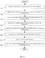
- FIG. 8 is a flow chart showing illustrative steps that a CAD tool (e.g., CAD tool 520 of FIG. 5 ) may perform to implement a circuit design in an integrated circuit and to sample signals of internal nodes from the integrated circuit for debugging the integrated circuit in real-time and at high-speed using a logic analyzer, similar to the operations that were performed on the gate-level descriptions of circuit designs 710 and 730 of FIGS. 7A and 7B , respectively.
- a CAD tool e.g., CAD tool 520 of FIG. 5
- FIG. 8 is a flow chart showing illustrative steps that a CAD tool (e.g., CAD tool 520 of FIG. 5 ) may perform to implement a circuit design in an integrated circuit and to sample signals of internal nodes from the integrated circuit for debugging the integrated circuit in real-time and at high-speed using a logic analyzer, similar to the operations that were performed on the gate-level descriptions of circuit designs 710 and 730 of FIGS. 7
- the CAD tool may receive a circuit design that includes a plurality of registers and first and second interconnects that are coupled between logic gates in the circuit design.
- the CAD tool may receive circuit design 710 of FIG. 7A or circuit design 730 of FIG. 7B .
- the CAD tool may perform a retiming operation of the circuit design to create a register-retimed circuit design.
- the CAD tool may remove registers 722, 724, and 726 from the inputs of combinational gate 713 of FIG. 7A and add registers 732 and 734 at the outputs of the combinational gate, thereby pushing a register forward across point P.
- the CAD tool may remove registers 732 and 734 from the outputs of combinational gate 713 of FIG. 7B and add register 722, 724, and 726 to the inputs of the combinational gate, thereby pushing a register backward across node Q.
- the CAD tool may record information about the retiming operation.
- the CAD tool may record information that include the move direction (e.g., forward or backward), the register type (e.g., clocking information such as clock signal name, frequency, and phase) of each register that is moved across the combinational gate.
- the move direction e.g., forward or backward
- the register type e.g., clocking information such as clock signal name, frequency, and phase
- the CAD tool may couple the first and second interconnects of the register-retimed circuit design to an acquisition storage circuit.
- the CAD tool may connect nodes P' and R' of integrated circuit 720 in FIG. 7A to acquisition storage circuit 760.
- the CAD tool may connect nodes Q' and S' of integrated circuit 740 in FIG. 7B to acquisition storage circuit 765.
- the CAD tool may add first and second latencies to the register-retimed circuit design between the respective first and second interconnects and the acquisition storage circuit based on the recorded information. For example, the CAD tool may insert one register between node P' and acquisition storage circuit 760 of FIG. 7A and zero registers between node R' and acquisition storage circuit 760. As another example, the CAD tool may insert one register between node S' and acquisition storage circuit 765 of FIG. 7B and zero registers between node Q' and acquisition storage circuit 765.
- the CAD tool may probe first and second signals at the respective first and second interconnects of the register-retimed circuit design. For example, the CAD tool may sample signals at nodes P' and R' of integrated circuit 720 of FIG. 7A . As another example, the CAD tool may sample signals at nodes Q' and S' of integrated circuit 740 of FIG. 7B .
- FIG. 9 is a flow chart showing illustrative steps that a logic analyzer (e.g., logic analyzer 619 of FIG. 6 as part of analysis tools 578 of FIG. 5 ) may perform for analyzing probed signals in a retimed design.
- a retiming operation may have moved a register across an interconnect in a circuit design to create the retimed design.
- the retiming operation may also have recorded information about the register move.
- the retiming operation may have moved registers 724 and 726 across node P of circuit design 710 of FIG. 7A to create integrated circuit 720 as the retimed design and recorded information that one register was moved forward across node P to create node P'.
- the logic analyzer may receive a tap point at the interconnect in the circuit design. For example, the logic analyzer may receive an instruction that node P is a tap point of circuit design 710 of FIG. 7A . In response to receiving the tap point, the logic analyzer may insert a route from the interconnect in the retimed design to a storage circuit during step 920. For example, the logic analyzer may couple point P' of integrated circuit 720 of FIG. 7A to acquisition storage circuit 760.
- the logic analyzer may direct the retimed design to store the probed signals in the storage circuit 760. For example, the logic analyzer may start sampling signals at point P' of integrated circuit 720 of FIG. 7A based on a trigger condition and store the sampled signals in acquisition storage circuit 760.
- the logic analyzer may retrieve the probed signals from the storage circuit for debugging.
- the logic analyzer may be coupled to acquisition storage circuit 760 of FIG. 7A (e.g., through a JTAG port) and retrieve the stored signals for further processing.
- the logic analyzer may compute an offset of the probed signals based on the recorded information.
- the logic analyzer may compute the difference between the number of registers moved forward across node P (i.e., one register) and the number of register moved backward across node P (i.e., zero registers) during the retiming operation, thereby compensating implicitly for the additional latency that the insertion of a register between P' and the acquisition storage would have caused.
- the logic analyzer may re-align the probed signals using the computed offset.
- the logic analyzer may show the signals that were sampled at point P' delayed by one clock cycle.
- the logic analyzer may display the re-aligned signals during step 970.
- the logic analyzer may provide the option to selectively switch between displaying the re-aligned signals and the probed signals. For example, the logic analyzer may offer the option to switch between showing the signals that were sampled at point P' and the signals that were sampled at point P' delayed by one clock cycle.
- FIG. 10 is a flow chart showing illustrative steps that a logic analyzer may perform for probing signals in a circuit in accordance with an embodiment.
- the logic analyzer may receive a retimed circuit design of a pre-retiming circuit design.
- the logic analyzer may receive first tap points in the pre-retiming circuit design and retiming information for the first tap points.
- the logic analyzer may receive pre-retiming circuit 730 and retimed circuit 740 of FIG. 7B , information about the retiming operation that pushed a register backward across point Q, and tap points Q and S.
- the logic analyzer may locate second tap points in the retimed circuit design that correspond to the first tap points in the pre-retiming circuit design.
- the logic analyzer may map tap points Q and S in the pre-retiming circuit 730 to tap points Q' and S' in the retimed circuit 740.
- the logic analyzer may for each point of the first tap points determine a minimum number of the difference between forward and backward pushed registers among the respective points.
- the logic analyzer may determine the difference between forward and backward pushed registers at points Q (i.e., minus one) and S (i.e., zero) and determine the minimum of the two differences (i.e., minus one).
- the logic analyzer may for each point of the first tap points subtract the determined minimum number from the respective difference between forward and backward pushed registers to determine the respective additional number of registers.
- the logic analyzer may for each point of the second tap points insert the respective additional number of registers of the corresponding point of the first tap points into the route between the respective point of the second tap points and the acquisition storage block.
- the logic analyzer may insert one register into the route between point S' and acquisition storage circuit 765.
- CMOS complementary metal-oxide-semiconductor
- CMOS complementary metal-oxide-semiconductor
- PAL programmable array logic
- PLA programmable logic arrays
- FPLA field programmable logic arrays
- EPLD electrically programmable logic devices
- EEPLD electrically erasable programmable logic devices
- LCDA logic cell arrays
- FPGA field programmable gate arrays
- ASSP application specific standard products
- ASICs application specific integrated circuits
- DSPs digital signal processors
- GPUs graphics processing units
- the integrated circuit described herein may be part of a data processing system that includes one or more of the following components; a processor; memory; I/O circuitry; and peripheral devices.
- the integrated circuit can be used in a wide variety of applications, such as computer networking, data networking, instrumentation, video processing, digital signal processing, or any suitable other application where the advantage of debugging a circuit design in real-time and at high-speed after a register retiming operation is desirable.
- Additional embodiment 1 A method for using a computer aided design tool implemented on computing equipment to probe signals, comprising: receiving a circuit design that includes a plurality of registers and first and second interconnects that are coupled between logic gates in the circuit design; performing a retiming operation on the circuit design to create a register-retimed circuit design; recording information about the retiming operation; coupling the first and second interconnects of the register-retimed circuit design to an acquisition storage circuit; adding a first latency to the register-retimed circuit design between the first interconnect and the acquisition storage circuit based on the recorded information; and adding a second latency to the register-retimed circuit design between the second interconnect and the acquisition storage circuit based on the recorded information.
- Additional embodiment 2 The method of additional embodiment 1, further comprising: probing a first signal at the first interconnect of the register-retimed circuit design and probing a second signal at the second interconnect of the register-retimed circuit design.
- Additional embodiment 3 The method of additional embodiment 2, further comprising: receiving the first probed signal that has been delayed by the first latency at the acquisition storage circuit for temporary storage; and receiving the second probed signal that has been delayed by the second latency at the acquisition storage circuit for temporary storage.
- Additional embodiment 4 The method of additional embodiment 1, wherein performing the retiming operation of the circuit design further comprises: moving a register in the plurality registers from a first position in the first interconnect to a second position in the first interconnect.
- moving the register further comprises: changing the configuration of a mode multiplexer that is coupled to the second position in the first interconnect from selecting a first input signal to selecting a second input signal, wherein the first input signal is driven by a routing multiplexer and the second input signal is driven by an interconnect register.
- moving the register further comprises: changing the configuration of an additional mode multiplexer that is coupled to the first position in the first interconnect from selecting a third input signal to selecting a fourth input signal, wherein the third input signal is driven by an additional interconnect register and the fourth input signal is driven by an additional routing multiplexer.
- Additional embodiment 7 The method of additional embodiment 1, wherein recording information about the retiming operation further comprises: updating a first register count of the first interconnect based on the retiming operation; and updating a second register count of the second interconnect based on the retiming operation.
- Additional embodiment 8 The method of additional embodiment 7, wherein updating the first register count further comprises: incrementing the first register count when a register of the plurality of registers is moved forward across the first interconnect.
- Additional embodiment 9 The method of additional embodiment 7, wherein updating the register count further comprises: decrementing the first register count when a register of the plurality of registers is moved backward across the first interconnect.
- Additional embodiment 10 The method of additional embodiment 7, further comprising: determining whether the first register count is smaller than the second register count.
- Additional embodiment 11 The method of additional embodiment 10, wherein adding the first latency and adding the second latency to the register-retimed circuit design further comprise: inserting first additional registers into the register-retimed circuit design between the first interconnect and the acquisition storage circuit based on the recorded information; and inserting second additional registers into the register-retimed circuit design between the second interconnect and the acquisition storage circuit based on the recorded information.
- Additional embodiment 12 The method of additional embodiment 11, wherein inserting first and second additional registers into the register-retimed circuit design between the respective first and second interconnects and the acquisition storage circuit based on the recorded information further comprises: in response to determining that the first register count is smaller than the second register count, subtracting the first register count from the second register count to determine a third register count; and inserting the third register count of second additional registers between the second interconnect and the acquisition storage circuit.
- Non-transitory computer-readable storage media for analyzing probed signals in a retimed design, wherein a register retiming operation moves a register across an interconnect of a circuit design to create the retimed design and records information about the register move, comprising instructions for: receiving a tap point at the interconnect in the circuit design; locating a retimed tap point in the retimed design based on the tap point in the circuit design; probing signals at the retimed tap point in the retimed design; and analyzing the probed signals by performing offset compensation based on the recorded information.
- Additional embodiment 14 The non-transitory computer-readable storage media of additional embodiment 13, wherein probing signals at the retimed tap point in the retimed design further comprises instruction for: inserting a route from the retimed tap point in the retimed design to a storage circuit.
- Additional embodiment 15 The non-transitory computer-readable storage media of additional embodiment 14, further comprising instruction for: directing the retimed design to store the probed signals in the storage circuit.
- Additional embodiment 16 The non-transitory computer-readable storage media of additional embodiment 15, further comprising instruction for: retrieving the probed signals from the storage circuit for debugging.
- analyzing the probed signals further comprises instruction for: computing an offset of the probed signals based on the recorded information.
- Additional embodiment 18 The non-transitory computer-readable storage media of additional embodiment 17, further comprising instruction for: re-aligning the probed signals using the computed offset.
- Additional embodiment 19 The non-transitory computer-readable storage media of additional embodiment 18, further comprising instruction for: displaying the re-aligned signals.
- Additional embodiment 20 The non-transitory computer-readable storage media of additional embodiment 18, further comprising instruction for: selectively switching between displaying the re-aligned signals and the probed signals.
- a method for using a circuit design tool implemented on computing equipment to probe signals in a pre-retiming circuit design comprising: with the circuit design tool implemented on the computing equipment, receiving a retimed circuit design of the pre-retiming circuit design; with the circuit design tool implemented on the computing equipment, receiving first tap points in the pre-retiming circuit design and retiming information for the first tap points; with the circuit design tool implemented on the computing equipment, locating second tap points in the retimed circuit design that correspond to the first tap points in the pre-retiming circuit design; with the circuit design tool implemented on the computing equipment, generating a route in the retimed circuit design from the second tap points to an acquisition storage block based on the retiming information; and with the circuit design tool implemented on the computing equipment, probing signals at the second tap points in the retimed circuit design.
- Additional embodiment 22 The method of additional embodiment 21, further comprising: sending the probed signals from the second tap points to the acquisition storage block; and storing the probed signals in the acquisition storage block for further analysis.
- Additional embodiment 23 The method of additional embodiment 22, wherein the retiming information includes for each point of the first tap points a respective difference in number between forward and backward pushed registers across the point, and wherein generating a route in the retimed circuit design from the second tap points to the acquisition storage block based on the retiming information further comprises: determining a minimum number of the difference in number between forward and backward pushed registers among the respective points.
- Additional embodiment 24 The method of additional embodiment 23, further comprising: for each point of the first tap points, subtracting the determined minimum number from the respective difference in number between forward and backward pushed registers to determine a respective additional number of registers.
- Additional embodiment 25 The method of additional embodiment 24, further comprising: for each point of the second tap points, inserting the respective additional number of registers of the corresponding point of the first tap points into the route between the respective point of the second tap points and the acquisition storage block.
Abstract
Description
- This relates to integrated circuits and, more particularly, to debugging an integrated circuit after register retiming operations.
- Every transition from one technology node to the next technology node has resulted in smaller transistor geometries and thus potentially more functionality implemented per unit of integrated circuit area. Synchronous integrated circuits have further benefited from this development as evidenced by reduced interconnect and cell delays, which have led to performance increases.
- To further increase the performance, solutions such as register retiming have been proposed, where registers are moved among portions of combinational logic, thereby achieving a more balanced distribution of delays between registers and thus potentially a higher clock frequency at which the integrated circuit may be operated.
- However, performing register retiming may be complicated and error prone, especially when different portions of the integrated circuit operate in different clock domains and when registers have different clocks, clock polarities, or particular reset, preset, and initialization constraints.
- In accordance with certain aspects of the invention, a computer aided design (CAD) tool may receive a circuit design. The circuit design may include multiple registers and first and second interconnects between gates. The CAD tool may perform a retiming operation on the circuit design to create a register-retimed circuit design and record information about the retiming operation. For the purpose of probing signals in the circuit design, the CAD tool may couple the first and second interconnects of the register-retimed circuit design to an acquisition storage circuit. The CAD tool may further insert first additional registers into the register-retimed circuit design between the first interconnect and the acquisition storage circuit based on the recorded information. The CAD tool may inserting second additional registers into the register-retimed circuit design between the second interconnect and the acquisition storage circuit based on the recorded information.
- It is appreciated that the present invention can be implemented in numerous ways, such as a process, an apparatus, a system, a device, or a method on a computer readable medium. Several inventive embodiments of the present invention are described below.
- In certain embodiments, the above-mentioned CAD tool may probe first and second signals at the respective first and second interconnects of the register-retimed circuit design. For this purpose, the CAD tool may send the first and second probed signals from the first and second interconnects through the first and second additional registers to the acquisition storage circuit.
- If desired, during the retiming operation of the circuit design, the CAD tool may move a register of the multiple registers across the first interconnect. For example, the CAD tool may change the configuration of a mode multiplexer that is coupled to an input of the first interconnect from selecting a first input signal to selecting a second input signal, where the first input signal is driven by a routing multiplexer and the second input signal is driven by the register.
- Further features of the invention, its nature and various advantages, will be more apparent from the accompanying drawings and the following detailed description of the preferred embodiments.
-
-
FIG. 1 is a diagram of an illustrative integrated circuit having an exemplary routing topology in accordance with an embodiment. -
FIG. 2 is a diagram of illustrative retiming operations in accordance with an embodiment. -
FIG. 3 is a diagram of an illustrative pipelined routing resource which uses a register to pipeline a routing signal in accordance with an embodiment. -
FIG. 4 is a diagram of a circuit design system that may be used to design integrated circuits in accordance with an embodiment. -
FIG. 5 is a diagram of illustrative computer-aided design (CAD) tools that may be used in a circuit design system in accordance with an embodiment. -
FIG. 6 is a flow chart of illustrative steps for designing an integrated circuit in accordance with an embodiment. -
FIG. 7A is a diagram of an illustrative circuit before a register retiming operation and with probed signals being routed to an acquisition storage circuit with forward pushed registers during a register retiming operation in accordance with an embodiment. -
FIG. 7B is a diagram of an illustrative circuit before a register retiming operation and with probed signals being routed to an acquisition storage circuit with backward pushed registers during a register retiming operation in accordance with an embodiment. -
FIG. 8 is a flow chart showing illustrative steps for performing register retiming operations in an integrated circuit and probing signals in the integrated circuit after the register retiming operations in accordance with an embodiment. -
FIG. 9 is a flow chart showing illustrative steps that a logic analyzer may perform for analyzing probed signals in a retimed design in accordance with an embodiment. -
FIG. 10 is a flow chart showing illustrative steps for probing signals in a circuit in accordance with an embodiment. - The presented embodiments relate to integrated circuits and, more particularly, to debugging an integrated circuit after register retiming operations.
- Performing register retiming to improve the performance of an integrated circuit may be complicated and error prone, especially when different portions of the integrated circuit operate in different clock domains and registers have different clocks, clock polarity, and/or particular reset, preset, or initialization constraints.
- In some scenarios, a circuit designer may wish to debug the implementation of a circuit design (e.g., an integrated circuit) in real-time. For example, if the output of a register of the integrated circuit is provided to an input-output (I/O) pin and is observed (e.g., with an oscilloscope or logic analyzer) to be stuck high rather than toggling, the circuit designer may wish to isolate the source of the failure (i.e., the source of the failure causing the output to be stuck high).
- For example, an interconnect that is shorted to a high or low logic level, a timing failure, a functional failure of the integrated circuit, or other types of failures may need to be isolated. Accordingly, the circuit designer may wish to tap, or sample, internal nets (e.g., the interconnect between a logic gate and the register or the interconnect between logic gates, etc.), which are sometimes also referred to as nodes or internal nodes, and observe the state of the signals at these nodes in order to isolate the failure.
- For example, the circuit designer may want to incrementally tap signals and follow a failure to its source. That is, the circuit designer may wish to follow the failure from the output of the register to the source by checking the signals at the interconnects in the cone of logic that ends at the input of the register. The designer may first tap the interconnect at the input of the register (e.g., between a logic gate and the register). Next, if tapping the interconnect at the input of the register is not believed to isolate the failure, the designer may tap the interconnects at the input of the logic gate.
- However, performing register retiming may change the behavior of many internal nodes (e.g., by moving one or more registers across an internal node), thereby changing the observed behavior of those internal nodes in the circuit design implementation. As a result, many internal nodes in the circuit design implementation may exhibit a behavior that is different than the originally intended behavior of the respective node as specified by the designer in the circuit design. However, the fact that the observed behavior is different than the desired behavior may not be indicative of an error in the circuit design implementation.
- It may therefore be desirable to record information about the registers that are moved during register retiming and to instrument the respective circuit design implementation accordingly such that a logic analyzer may be used to debug the circuit design implementation after a register retiming operation has been performed.
- It will be recognized by one skilled in the art, that the present exemplary embodiments may be practiced without some or all of these specific details. In other instances, well-known operations have not been described in detail in order not to unnecessarily obscure the present embodiments.
- An illustrative embodiment of an integrated circuit such as programmable logic device (PLD) 100 that may be configured to implement a circuit design is shown in
FIG. 1 . As shown inFIG. 1 , the programmable logic device (PLD) may include a two-dimensional array of functional blocks, including logic array blocks (LABs) 110 and other functional blocks, such as random access memory (RAM) blocks 130 and digital signal processing (DSP) blocks 120, for example. Functional blocks such asLABs 110 may include smaller programmable regions (e.g., logic elements, configurable logic blocks, or adaptive logic modules) that receive input signals and perform custom functions on the input signals to produce output signals. -
Programmable logic device 100 may contain programmable memory elements. Memory elements may be loaded with configuration data (also called programming data) using input-output elements (IOEs) 102. Once loaded, the memory elements each provide a corresponding static control signal that controls the operation of an associated functional block (e.g.,LABs 110, DSP 120,RAM 130, or input-output elements 102). - In a typical scenario, the outputs of the loaded memory elements are applied to the gates of metal-oxide-semiconductor transistors in a functional block to turn certain transistors on or off and thereby configure the logic in the functional block including the routing paths. Programmable logic circuit elements that may be controlled in this way include parts of multiplexers (e.g., multiplexers used for forming routing paths in interconnect circuits), look-up tables, logic arrays, AND, OR, NAND, and NOR logic gates, pass gates, etc.
- The memory elements may use any suitable volatile and/or non-volatile memory structures such as random-access-memory (RAM) cells, fuses, antifuses, programmable read-only-memory memory cells, mask-programmed and laser-programmed structures, combinations of these structures, etc. Because the memory elements are loaded with configuration data during programming, the memory elements are sometimes referred to as configuration memory, configuration RAM (CRAM), or programmable memory elements.
- In addition, the programmable logic device may have input-output elements (IOEs) 102 for driving signals off of PLD and for receiving signals from other devices. Input-
output elements 102 may include parallel input-output circuitry, serial data transceiver circuitry, differential receiver and transmitter circuitry, or other circuitry used to connect one integrated circuit to another integrated circuit. As shown, input-output elements 102 may be located around the periphery of the chip. If desired, the programmable logic device may have input-output elements 102 arranged in different ways. For example, input-output elements 102 may form one or more columns of input-output elements that may be located anywhere on the programmable logic device (e.g., distributed evenly across the width of the PLD). If desired, input-output elements 102 may form one or more rows of input-output elements (e.g., distributed across the height of the PLD). Alternatively, input-output elements 102 may form islands of input-output elements that may be distributed over the surface of the PLD or clustered in selected areas. - The PLD may also include programmable interconnect circuitry in the form of vertical routing channels 140 (i.e., interconnects formed along a vertical axis of PLD 100) and horizontal routing channels 150 (i.e., interconnects formed along a horizontal axis of PLD 100), each routing channel including at least one track to route at least one wire. If desired, the interconnect circuitry may include pipeline elements, and the contents stored in these pipeline elements may be accessed during operation. For example, a programming circuit may provide read and write access to a pipeline element.
- Note that other routing topologies, besides the topology of the interconnect circuitry depicted in
FIG. 1 , may be used. For example, the routing topology may include wires that travel diagonally or that travel horizontally and vertically along different parts of their extent as well as wires that are perpendicular to the device plane in the case of three dimensional integrated circuits, and the driver of a wire may be located at a different point than one end of a wire. The routing topology may include global wires that span substantially all ofPLD 100, fractional global wires such as wires that span part ofPLD 100, staggered wires of a particular length, smaller local wires, or any other suitable interconnection resource arrangement. - If desired, programmable logic device (PLD) 100 may be configured to implement a circuit design. For example, the configuration RAM may be programmed such that
LABs 110,DSP 120, andRAM 130, programmable interconnect circuitry (i.e.,vertical channels 140 and horizontal channels 150), and the input-output elements 102 form the circuit design implementation. - For debugging purposes, a logic analyzer may provide the control to select specific nodes inside the circuit design, thereby instrumenting the circuit design implementation in
PLD 100. The logic analyzer may capture data at those nodes and route the captured data to acquisition storage circuit, which may be one or more ofRAM 130, and access the captured data for debugging. Alternatively, the logic analyzer may route the captured data to input-output elements 102 and use an external logic analyzer or oscilloscope for debugging. - It should be understood that embodiments may be implemented in any integrated circuit and that a logic analyzer may probe any node of any functional block in such an integrated circuit. If desired, these functional blocks may be arranged in multiple levels or layers in which multiple functional blocks are interconnected to form still larger blocks.
-
FIG. 2 shows an example of different versions of a circuit design that PLD 100 may implement. The first version of the circuit design may includeregisters combinational logic 245.Register 210 may send a signal to register 220; register 220 may send the signal throughcombinational logic 245 to register 230; and register 230 may send the signal to register 240. As an example, the delay on the path fromregister 220 throughcombinational logic 245 to register 230 may have a delay of 6 nanoseconds (ns), whereas the delay betweenregister registers - Performing register retiming on the first version of the circuit design may create a second version of the circuit design. For example, register 230 may be pushed back through a portion of
combinational logic 245, thereby separatingcombinational logic 245 of the first version of the circuit design intocombinational logic combinational logic 242 to register 230; and register 230 may send the signal throughcombinational logic 244 to register 240. - As an example, the delay on the path from
register 220 throughcombinational logic 242 to register 230 may have a delay of 4ns, and the delay fromregister 230 throughcombinational logic 244 to register 240 may have a delay of 2ns. Thus, the second version of the circuit design may operate at a frequency of 250 MHz. - Performing register retiming on the second version of the circuit design may create a third version of the circuit design. For example, register 220 may be pushed forward through a portion of
combinational logic 242, thereby separatingcombinational logic 242 of the second version of the circuit design intocombinational logic combinational logic 241 to register 220; register 220 may send the signal throughcombinational logic 243 to register 230; and register 230 may send the signal throughcombinational logic 244 to register 240. - As an example, the delay on the paths from
register 210 throughcombinational logic 241 to register 220, fromregister 220 throughcombinational logic 243 to register 230, and fromregister 230 throughcombinational logic 244 to register 240 may all have a delay of 2ns. Thus, the third version of the circuit design may operate at a frequency of 500 MHz, which is thrice the frequency at which the first version of the circuit design may operate. - If desired, routing resources such as the
vertical routing channels 140 or thehorizontal routing channels 150 ofFIG. 1 may include pipeline elements, which can facilitate register retiming.FIG. 3 depicts a pipelinedrouting resource 300 which uses a register in accordance with an embodiment. As shown, the pipelinedrouting resource 300 includes afirst multiplexer 302, adriver 304, aregister 306, and asecond multiplexer 308. -
Multiplexer 302 may be a driver input multiplexer (DIM) or a functional block input multiplexer (FBIM). A DIM may select a signal from multiple sources and send the selected signal todriver 304 that drives the wire. The multiple sources may include signals from outputs of functional blocks and other routing wires that travel in the same or in an orthogonal direction to the wire. A FBIM outputs a signal to a functional block and may select the signal from multiple routing wires. - As shown in
FIG. 3 , in accordance with an embodiment of the invention, themultiplexer 302 may be pipelined by providing its output to the data input ofregister 306.Multiplexer 308 in the pipelinedrouting resource 300 may receive the output ofmultiplexer 302 directly and may also receive the data output fromregister 306. - Although the pipelined
routing resource 300 includes a register, it will be recognized by one skilled in the art that different register implementations may be used to store a routing signal such as an edge-triggered flip-flop, a pulse latch, a transparent-low latch, a transparent-high latch, just to name a few. Thus, in order not to unnecessarily obscure the present embodiments, we refer to the storage circuit in the pipelined routing resource as a pipeline storage element. -
Multiplexer 308 may enable the pipelinedrouting resource 300 to be either used in a non-pipeline mode or in a pipeline register mode. In the non-pipeline mode, the output ofmultiplexer 308 selects the direct output ofmultiplexer 302. - In the pipeline mode,
multiplexer 308 may select the output ofregister 306.Multiplexer 308 may provide its output todriver circuit 304, and the output ofdriver circuit 304 may be used to drive a routing wire. The routing wire may span multiple functional blocks (e.g., for a pipelined routing resource with a DIM). Alternatively, the routing wire may be inside a functional block (e.g., for a pipelined routing resource with a FBIM). - Every DIM/FBIM may include a register such as
register 306 such that all the routing multiplexers are pipelined. However, in some embodiments, that may be unnecessary as the capabilities provided may exceed design requirements. Thus, in certain embodiments only a fraction, such as one-half or one-fourth, of the routing multiplexers may be pipelined. For example, a signal may take 150 picoseconds (ps) to traverse a wire of a given length, but a clock signal may be constrained to operate with a 650 ps clock cycle. Thus, providing a pipeline register such asregister 306 every fourth wire may be sufficient in this example. Alternatively the registers may be placed more frequently than every fourth wire (e.g., every second wire) to provide a higher degree of freedom in selection of which registers are used. - Pipelined routing resources such as pipelined
routing resource 300 may facilitate register retiming operations, such as the register retiming illustrated inFIG. 2 . For example, consider the scenario in which register 230 is implemented by a first instance of a pipelined routing element that is operated in pipeline register mode (i.e., register 230 is implemented byregister 306 of a first instance of a pipelined routing resource 300). Consider further that the path fromregister 220 throughcombinational logic 245 to register 230 includes a second instance of a pipelined routing element that is operated in non-pipeline mode. Thus, switching the first instance of the pipelined routing element from operating in pipeline register mode to operating in non-pipeline mode and switching the second instance of the pipelined routing element from operating in non-pipeline mode to operating in pipeline register mode may transform the first version into the second version of the circuit design presented inFIG. 2 . - CAD tools in a circuit design system may evaluate whether register retiming may improve the performance of a current version of a circuit design or whether the current version of the circuit design meets a given performance criterion. If desired, and in the event that the CAD tools determine that register retiming would improve the performance of the current version of the circuit design or that the current version of the circuit design misses the given performance criterion, the CAD tools may execute register retiming operations that transform the current version of the circuit design into another version of the circuit design (e.g., as illustrated in
FIG. 2 ). - An illustrative
circuit design system 400 in accordance with an embodiment is shown inFIG. 4 .System 400 may be based on one or more processors such as personal computers, workstations, etc. The processor(s) may be linked using a network (e.g., a local or wide area network). Memory in these computers or external memory and storage devices such as internal and/or external hard disks may be used to store instructions and data. - Software-based components such as computer-aided
design tools 420 anddatabases 430 reside onsystem 400. During operation, executable software such as the software of computer aideddesign tools 420 runs on the processor(s) ofsystem 400.Databases 430 are used to store data for the operation ofsystem 400. In general, software and data may be stored on any computer-readable medium (storage) insystem 400. Such storage may include computer memory chips, removable and fixed media such as hard disk drives, flash memory, compact discs (CDs), digital versatile discs (DVDs), blu-ray discs (BDs), other optical media, and floppy diskettes, tapes, or any other suitable memory or storage device(s). When the software ofsystem 400 is installed, the storage ofsystem 400 has instructions and data that cause the computing equipment insystem 400 to execute various methods (processes). When performing these processes, the computing equipment is configured to implement the functions of the circuit design system. - The computer aided design (CAD)
tools 420, some or all of which are sometimes referred to collectively as a CAD tool, a circuit design tool, or an electronic design automation (EDA) tool, may be provided by a single vendor or by multiple vendors.Tools 420 may be provided as one or more suites of tools (e.g., a compiler suite for performing tasks associated with implementing a circuit design in a programmable logic device) and/or as one or more separate software components (tools). Database(s) 430 may include one or more databases that are accessed only by a particular tool or tools and may include one or more shared databases. Shared databases may be accessed by multiple tools. For example, a first tool may store data for a second tool in a shared database. The second tool may access the shared database to retrieve the data stored by the first tool. This allows one tool to pass information to another tool. Tools may also pass information between each other without storing information in a shared database if desired. - Illustrative computer aided
design tools 520 that may be used in a circuit design system such ascircuit design system 400 ofFIG. 4 are shown inFIG. 5 . - The design process may start with the formulation of functional specifications of the integrated circuit design (e.g., a functional or behavioral description of the integrated circuit design). A circuit designer may specify the functional operation of a desired circuit design using design and
constraint entry tools 564. Design andconstraint entry tools 564 may include tools such as design andconstraint entry aid 566 anddesign editor 568. Design and constraint entry aids such asaid 566 may be used to help a circuit designer locate a desired design from a library of existing circuit designs and may provide computer-aided assistance to the circuit designer for entering (specifying) the desired circuit design. - As an example, design and
constraint entry aid 566 may be used to present screens of options for a user. The user may click on on-screen options to select whether the circuit being designed should have certain features.Design editor 568 may be used to enter a design (e.g., by entering lines of hardware description language code), may be used to edit a design obtained from a library (e.g., using a design and constraint entry aid), or may assist a user in selecting and editing appropriate prepackaged code/designs. - Design and
constraint entry tools 564 may be used to allow a circuit designer to provide a desired circuit design using any suitable format. For example, design andconstraint entry tools 564 may include tools that allow the circuit designer to enter a circuit design using truth tables. Truth tables may be specified using text files or timing diagrams and may be imported from a library. Truth table circuit design and constraint entry may be used for a portion of a large circuit or for an entire circuit. - As another example, design and
constraint entry tools 564 may include a schematic capture tool. A schematic capture tool may allow the circuit designer to visually construct integrated circuit designs from constituent parts such as logic gates and groups of logic gates. Libraries of preexisting integrated circuit designs may be used to allow a desired portion of a design to be imported with the schematic capture tools. - If desired, design and
constraint entry tools 564 may allow the circuit designer to provide a circuit design to thecircuit design system 400 using a hardware description language such as Verilog hardware description language (Verilog HDL), Very High Speed Integrated Circuit Hardware Description Language (VHDL), SystemVerilog, or a higher-level circuit description language such as OpenCL or SystemC, just to name a few. The designer of the integrated circuit design can enter the circuit design by writing hardware description language code witheditor 568. Blocks of code may be imported from user-maintained or commercial libraries if desired. - After the design has been entered using design and
constraint entry tools 564, behavioral simulation tools 572 may be used to simulate the functional performance of the circuit design. If the functional performance of the design is incomplete or incorrect, the circuit designer can make changes to the circuit design using design andconstraint entry tools 564. The functional operation of the new circuit design may be verified using behavioral simulation tools 572 before synthesis operations have been performed usingtools 574. Simulation tools such as behavioral simulation tools 572 may also be used at other stages in the design flow if desired (e.g., after logic synthesis). The output of the behavioral simulation tools 572 may be provided to the circuit designer in any suitable format (e.g., truth tables, timing diagrams, etc.). - Once the functional operation of the circuit design has been determined to be satisfactory, logic synthesis and
optimization tools 574 may generate a gate-level netlist of the circuit design, for example using gates from a particular library pertaining to a targeted process supported by a foundry, which has been selected to produce the integrated circuit. Alternatively, logic synthesis andoptimization tools 574 may generate a gate-level netlist of the circuit design using gates of a targeted programmable logic device (i.e., in the logic and interconnect resources of a particular programmable logic device product or product family). - Logic synthesis and
optimization tools 574 may optimize the design by making appropriate selections of hardware to implement different logic functions in the circuit design based on the circuit design data and constraint data entered by the logicdesigner using tools 564. As an example, logic synthesis andoptimization tools 574 may perform register retiming on the circuit design based on the length of a combinational path between registers in the circuit design and corresponding timing constraints that were entered by the logicdesigner using tools 564. - After logic synthesis and
optimization using tools 574, the circuit design system may use tools such as placement androuting tools 576 to perform physical design steps (layout synthesis operations). Placement androuting tools 576 are used to determine where to place each gate of the gate-level netlist produced bytools 574. For example, if two counters interact with each other, the placement androuting tools 576 may locate these counters in adjacent regions to reduce interconnect delays or to satisfy timing requirements specifying the maximum permitted interconnect delay. The placement androuting tools 576 create orderly and efficient implementations of circuit designs for any targeted integrated circuit (e.g., for a given programmable integrated circuit such as a field-programmable gate array (FPGA).) - Tools such as
tools tools tools - As an example,
tools Tools FIG. 2 . If desired,tools routing resource 300 ofFIG. 3 to operate in non-pipeline mode or as a pipelined routing element. - After an implementation of the desired circuit design has been generated using placement and
routing tools 576, the implementation of the design may be analyzed and tested usinganalysis tools 578. For example,analysis tools 578 may include timing analysis tools, power analysis tools, or formal verification tools, just to name few. - After satisfactory optimization operations have been completed using
tools 520 and depending on the targeted integrated circuit technology,tools 520 may produce a mask-level layout description of the integrated circuit or configuration data for programming the programmable logic device. - In certain embodiments, tools such as
tools tools tools 578 may tap the probes (i.e., extract the state of those internal nodes) during execution of the design implementation in the integrated circuit. If desired,tools 578 may facilitate the analysis of the tapped probes, for example by displaying the tapped probes as waveforms. - Illustrative operations involved in using
tools 520 ofFIG. 5 to produce the mask-level layout description of the integrated circuit are shown inFIG. 6 . As shown inFIG. 6 , a circuit designer may first provide adesign specification 602. Thedesign specification 602 may, in general, be a behavioral description provided in the form of an application code (e.g., C code, C++ code, SystemC code, OpenCL code, etc.). In some scenarios, the design specification may be provided in the form of a register transfer level (RTL)description 606. - The RTL description may have any form of describing circuit functions at the register transfer level. For example, the RTL description may be provided using a hardware description language such as the Verilog hardware description language (Verilog HDL or Verilog), the SystemVerilog hardware description language (SystemVerilog HDL or SystemVerilog), or the Very High Speed Integrated Circuit Hardware Description Language (VHDL). If desired, a portion or all of the RTL description may be provided as a schematic representation.
- In general, the
behavioral design specification 602 may include untimed or partially timed functional code (i.e., the application code does not describe cycle-by-cycle hardware behavior), whereas theRTL description 606 may include a fully timed design description that details the cycle-by-cycle behavior of the circuit at the register transfer level. -
Design specification 602 orRTL description 606 may also include target criteria such as area use, power consumption, delay minimization, clock frequency optimization, or any combination thereof. The optimization constraints and target criteria may be collectively referred to as constraints. - Those constraints can be provided for individual data paths, portions of individual data paths, portions of a design, or for the entire design. For example, the constraints may be provided with the
design specification 602, the RTL description 606 (e.g., as a pragma or as an assertion), in a constraint file, or through user input (e.g., using the design andconstraint entry tools 564 ofFIG. 5 ), to name a few. - In certain embodiments, a given data path may have more than one constraint associated with the path, and some of these constraints may be in conflict with each other e.g., a constraint received with the behavioral design specification for a given path may conflict with the constraint received with the RTL description and with a constraint received with a constraint file. In this scenario, a predetermined priority of constraints, which may be defined explicitly or resolved implicitly by
CAD tools 520, may determine which of the conflicting constraints is selected. For example, the constraint from the user or a configuration file may override the constraints received from other sources, and a constraint received with the RTL description may override a constraint received with the behavioral design specification. - The constraints may target the entire circuit design or portions of the circuit design. For example, some constraints may be defined globally and thus be applicable to the entire circuit design. Other constraints may be assigned locally and thus be applicable only to the corresponding portions of the circuit design. Consider the scenario in which the circuit design is organized hierarchically. In this scenario, every hierarchical instance may include different assignments. In other words, multiple different constraints may target the same portion of the circuit design, and priorities may be defined explicitly or resolved implicitly by
CAD tools 520. For example, a constraint defined at a higher level of the design hierarchy may override a constraint at a lower level. Alternatively, a constraint defined at a lower level of the design hierarchy may override a constraint at a higher level, or individual levels of the design hierarchy may be given priority over other levels of design hierarchy. - Constraints included in
design specification 602 orRTL description 606 may be conveyed toCAD tools 520 in the form of variables, parameters, compiler directives, macros, pragmas, or assertions, just to name a few.CAD tools 520 may use a constraint file, which may include a portion or all of the constraints. Such a constraint file may be included withdesign specification 602 orRTL description 606. In some scenarios, a portion or all of the constraints may be embedded in the circuit design. Alternatively, the constraints may have been defined using the design and constraint entry tools 564 (seeFIG. 5 ). - At
step 604, behavioral synthesis (sometimes also referred to as algorithmic synthesis) may be performed to convert the behavioral description into anRTL description 606. Step 604 may be skipped if the design specification is already provided in form of an RTL description. - At
step 618, behavioral simulation tools 572 may perform an RTL simulation of the RTL description, which may verify the functional performance of the RTL description. If the functional performance of the RTL description is incomplete or incorrect, the circuit designer can make changes to the HDL code (as an example). DuringRTL simulation 618, actual results obtained from simulating the behavior of the RTL description may be compared with expected results. - During
step 608, logic synthesis operations may generate gate-level description 610 using logic synthesis andoptimization tools 574 fromFIG. 5 . If desired, logic synthesis operations may perform register retiming as illustrated inFIG. 2 according to the constraints that are included indesign specification 602 orRTL description 606. - During
step 612, physical synthesis operations (e.g., place and route and optimization operations using for example placement and routing tools 576) may place and connect the different gates in gate-level description 610 in a preferred location on the targeted integrated circuit to meet given target criteria (e.g., minimize area and maximize routing efficiency or minimize path delay and maximize clock frequency or any combination thereof). - If desired, physical synthesis operations may perform register retiming as illustrated in
FIG. 2 and according to the constraints that are included indesign specification 602 orRTL description 606. As an example, physical synthesis operations may perform register retiming by changing the configuration of some pipelined routing resources (e.g., some instances of pipelinedrouting resource 300 ofFIG. 3 ) from operating in pipeline register mode to operating in non-pipelined mode and the configuration of other pipelined routing resources (e.g., other instances of pipelinedrouting resources 300 ofFIG. 3 ) from operating in non-pipelined mode to operating in pipeline register mode. The output ofphysical synthesis 612 is a mask-level layout description 616. -
Circuit design system 400 may include a timing estimator (e.g., formed as part ofoptimization tools 574,tools 576, or tools 578) that may be used to estimate delays between synchronous elements of the circuit design duringstep 614. For example, timing estimator may estimate delays between sequential elements such as registers and storage circuits (e.g., based on the lengths of interconnects, intermediate combinational logic, etc.). The delays may, if desired, be estimated based on metrics such as slack (e.g., the difference between a required arrival time and the arrival time of a signal), slack-ratios, interconnect congestion, or other timing metrics.Circuit design system 400 may use the estimated delays to determine the locations of groups of circuitry while helping to ensure that delays satisfy timing requirements (e.g., critical path delay requirements) or other performance constraints. - Consider the scenario in which a circuit design has a given path from a register through combinational logic to another register and that this given path misses one or more target criteria. For example, the timing estimator may determine that the given path is associated with a delay that is larger than the target delay specified for the path as one of the target criteria. The timing estimator may detect that the given path has a larger delay before, during, and after
logic synthesis 608 or before, during, and afterphysical synthesis 612, which may include operations such as clustering, partitioning, placement, and routing, just to name a few. In this scenario,logic synthesis 608 orphysical synthesis 612 may perform register retiming (e.g., the register retiming operations described inFIG. 2 ), thereby reducing the delay through the combinational logic between the registers and potentially improving the performance of the given path. - If desired, the tool that executes the register retiming operation may record information about the register retiming operation. For example, the tool may record information about the number of registers pushed forward through a node, the number of registers pushed backward through a node, the difference between the number of registers pushed forward minus the number of registers pushed backward, etc. If desired, the tool may record information about each register. For example, the tool may record clocking information (e.g., the name of the clock signal, the frequency, the phase, etc.), information about initial conditions, and information about reset conditions (e.g., asynchronous reset and/or synchronous reset), to name a few.
-
Circuit design system 400 may include a logic analyzer (e.g., formed as part of tools 578) that a circuit designer may use for debugging the integrated circuit that implements the circuit design in real-time and at high-speed. As shown,logic analyzer 619 may insert taps into theRTL description 606, the gate-level description 610, and/or the mask-level description 616 to capture signals from internal circuit design nodes. If desired,logic analyzer 619 may also provide the control to add or to delete nodes that are tapped in an existing debugging process.Logic analyzer 619 may provide a connection from all selected nodes to an acquisition storage circuit or a connection from those nodes to an input-output pin. - After a change in the selection of nodes,
tools logic analyzer 619 may add nodes to the selection of nodes and the routing connections between those nodes and the acquisition storage circuit toRTL description 606. The change inRTL description 606 may require the execution of logic synthesis operations duringstep 608 and the execution of physical synthesis operations duringstep 612. In certain embodiments, logic analyzer may provide the control to enable, disable or modify nodes in gate-level description 610 or mask-level layout description 616 without fully recompiling the circuit design. For example, changing the node selection in the gate-level description may only require the execution of physical synthesis operations duringstep 612. - In certain embodiments,
tool 574 may perform incremental logic synthesis operations duringstep 608 as a result of incremental changes inRTL description 606. Incremental logic synthesis operations may preserve the majority of the original gate-level description 610 while restricting modifications to the portions of the gate-level description that are affected by the incremental changes inRTL description 606. - Similarly,
tool 576 may perform incremental physical synthesis operations duringstep 612 as a result of incremental changes in gate-level description 610. Incremental physical synthesis operations may preserve the majority of the original mask-level layout description 616 while restricting modifications to the portions of the mask-level layout description that are affected by the incremental changes in gate-level description 610. - Inserting taps to sample signals (e.g., with logic analyzer 619) at selected internal nodes or making changes to the node selection that a circuit designer wants to sample with
logic analyzer 619 may result in incremental changes toRTL description 606, gate-level description 610 and/or mask-level layout description 616. These changes toRTL description 606, gate-level description 610 and/or mask-level layout description 616 may be caused by the insertion of routing connections between the added nodes and the acquisition storage circuit or input-output pins and the removal of routing connections between the removed nodes and the acquisition storage circuit or input-output pins. As a result,tools step 608 and incremental physical synthesis operations duringstep 612, respectively. -
Logic analyzer 619 may provide the control to set trigger conditions up and sample data according to those trigger conditions. As an example, trigger conditions may describe logic events with logic conditions for signals. If desired, trigger conditions may be based on a sequence of events involving comparisons, logical operators, and/or reduction operators. Trigger conditions may specify whenlogic analyzer 619 starts and stops data acquisition from the tap points. -
Logic analyzer 619 may add trigger conditions in form of RTL code toRTL description 606 or in form of a gate-level netlist to gate-level description 610. A change inRTL description 606 may require the execution of logic synthesis operations duringstep 608 and the execution of physical synthesis operations duringstep 612. A change in gate-level description 610 may require the execution of physical synthesis operations duringstep 612. Logic synthesis operations and/or physical synthesis operations may be incremental (i.e., limited to the modified portion of theRTL description 606 and/or the modified portion of the gate-level description 610). -
Logic analyzer 619 may perform data acquisition during the operation of the integrated circuit that implements the circuit design. During data acquisition,logic analyzer 619 may capture data from the tap points into the acquisition storage circuit continuously. - For the purpose of data analysis,
logic analyzer 619 may route the captured data from the acquisition storage circuit via the JTAG port to a waveform display pane or to input-output pins of the integrated circuit for use by an external logic analyzer or oscilloscope. - The waveform display pane may allow for viewing, printing, or editing of waveform views of the captured data. As an example, the waveform display pane may allow for inserting time bars, further editing the properties of nodes, editing buses and bus values, and printing waveforms, just to name a few.
Logic analyzer 619 may also allow for exporting the data into another format for further analysis. - As an example, consider
circuit design 710 ofFIG. 7A (e.g., in form of gate-level description 610 ofFIG. 6 ) andintegrated circuit 720 as the implementation of the circuit design (e.g., in form of mask-level layout description 616 ofFIG. 6 ). As shown,circuit design 710 andintegrated circuit 720 may include pipelinedrouting resources routing resource 300 ofFIG. 3 ), logic ANDgate 716 andcombinational gate 713, which may include logic ANDgates - Consider further that
circuit design 710 operates pipelinedrouting resources routing resources CAD tool 520 ofFIG. 5 ) may perform a register retiming operation oncircuit design 710. For example, the register retiming operation may configure pipelinedrouting resources routing resources combinational gate 713 and creatingintegrated circuit 720. - If desired, the CAD tool may record information about the register retiming information. For example, the CAD tool may for each node (e.g., for nodes P and R) record the difference between registers pushed forward through the node and registers pushed backward through the node. In the example of
integrated circuit 720, nodes P' and R' may have a difference between forward and backward pushed registers that is equal to one and zero, respectively. - As an example, consider that the user wants to probe, or sample, signals at the output of logic AND
gates level description 610 ofFIG. 6 ) at nodes P and R (i.e., at the outputs of logic ANDgates 714 and 716) to capture signals from those nodes. A logic analyzer (e.g.,logic analyzer 619 ofFIG. 6 ) may provideacquisition storage circuit 760 and a connection from the outputs of logic ANDgates acquisition storage circuit 760. A CAD tool (e.g.,tool 576 ofFIG. 5 ) may incrementally recreateintegrated circuit 720 with connections from retimed nodes P' and R' toacquisition storage 760, which may store the probed signals for further analysis. - During the analysis of the probed signals, a CAD tool may compare the expected value at node P at the output of logic AND
gate 714 incircuit design 710 with the probed signal at node P' at the output of logic ANDgate 714 inintegrated circuit 720. - In this example, nodes P and P' may not be equivalent after the same number of clock cycles. However, nodes P and P' may be equivalent after a different number of clock cycles. For example, node P' delayed by one clock cycle may be equivalent to node P.
- If desired, the logic analyzer may compute an offset for the data sampled at node P'. The logic analyzer may compensate for the offset and re-align the data to node P (e.g., in the waveform display pane). If desired, the logic analyzer may provide the control to switch between viewing the actually sampled data at node P' and the re-aligned data at node P.
- Alternatively, the logic analyzer may determine a number of registers to insert between each tap point and the acquisition storage circuit based on the recorded register retiming information. For example, the logic analyzer may for all sampled nodes determine the minimum of the difference between forward and backward pushed registers (i.e., zero for node R') and add the absolute value of that difference to the difference recorded for each sampled node (i.e., one for P' and zero for R') to determine the number of registers that need to be inserted between the respective node and the acquisition storage circuit.
- In the example of
integrated circuit 720, one register (e.g., register 752) needs to be inserted between node P' andacquisition storage circuit 760, whereas no register needs to be inserted between node R' andacquisition storage circuit 760 inintegrated circuit 720. - As another example, consider
circuit design 730 ofFIG. 7B (e.g., in form of gate-level description 610 ofFIG. 6 ) andintegrated circuit 740 as the implementation of the circuit design (e.g., in form of mask-level layout description 616 ofFIG. 6 ). As shown,circuit design 730 andintegrated circuit 740 may include pipelinedrouting resources routing resource 300 ofFIG. 3 ), logic ANDgate 716 andcombinational gate 713, which may include logic ANDgates - Consider further that
circuit design 730 operates pipelinedrouting resources routing resources CAD tool 520 ofFIG. 5 ) may perform a register retiming operation oncircuit design 730. For example, the register retiming operation may configure pipelinedrouting resources routing resources combinational gate 713 and creatingintegrated circuit 740. - If desired, the CAD tool may record information about the register retiming information. For example, the CAD tool may for each node (e.g., for nodes Q and S) increment a register count when a register is moved forward across the node and decrement the register count when a register is moved backward across the node, thereby recording the difference between registers pushed forward through the node and registers pushed backward through the node. In the example of
integrated circuit 740, nodes Q' and S' may have a difference between forward and backward pushed registers that is equal to minus one and zero, respectively. - As an example, consider that the user wants to probe, or sample, signals at the output of logic AND
gates level description 610 ofFIG. 6 ) at nodes Q and S (i.e., at the outputs of logic ANDgates 714 and 716) to capture signals from those nodes. A logic analyzer (e.g.,logic analyzer 619 ofFIG. 6 ) may provideacquisition storage circuit 765 and a connection from the outputs of logic ANDgates acquisition storage circuit 765. A CAD tool (e.g.,tool 576 ofFIG. 5 ) may incrementally recreateintegrated circuit 740 with connections from retimed nodes Q' and S' toacquisition storage 765, which may store the probed signals for further analysis. - During debugging, a CAD tool may analyze the probed signals at nodes Q' and S' at the output of logic AND
gates integrated circuit 740 based on the knowledge of nodes Q and S incircuit design 730. In this example, nodes Q and S are delayed by one clock cycle relative to each other and nodes Q' and S' are not. Thus, node S' delayed by one clock cycle may provide the same one clock cycle delay between nodes Q' and S' than between nodes Q and S. - If desired, the logic analyzer may compute an offset for the data sampled at nodes Q' and S'. The logic analyzer may compensate for the offset and re-align the data to nodes Q and S (e.g., in the waveform display pane). If desired, the logic analyzer may provide the control to switch between viewing the actually sampled data at nodes Q' and S' and the re-aligned data at nodes Q and S.
- Alternatively, the logic analyzer may determine a number of registers to insert between each tap point and the acquisition storage circuit based on the recorded register retiming information. For example, the logic analyzer may for all sampled nodes determine the minimum of the difference between forward and backward pushed registers (i.e., minus one for node Q' and zero for node S') and add the absolute value of that difference (i.e., one) to the difference recorded for each sampled node (i.e., zero plus one equals one for S' and minus one plus one equals zero for Q') to determine the number of registers that need to be inserted between the respective node and the acquisition storage circuit.
- In the example of
integrated circuit 740, one register (e.g., register 754) needs to be inserted between node S' andacquisition storage circuit 765; and no register needs to be inserted between node Q' andacquisition storage circuit 765. -
FIG. 8 is a flow chart showing illustrative steps that a CAD tool (e.g.,CAD tool 520 ofFIG. 5 ) may perform to implement a circuit design in an integrated circuit and to sample signals of internal nodes from the integrated circuit for debugging the integrated circuit in real-time and at high-speed using a logic analyzer, similar to the operations that were performed on the gate-level descriptions of circuit designs 710 and 730 ofFIGS. 7A and7B , respectively. - During
step 810, the CAD tool may receive a circuit design that includes a plurality of registers and first and second interconnects that are coupled between logic gates in the circuit design. For example, the CAD tool may receivecircuit design 710 ofFIG. 7A orcircuit design 730 ofFIG. 7B . - During
step 820, the CAD tool may perform a retiming operation of the circuit design to create a register-retimed circuit design. As an example, the CAD tool may removeregisters combinational gate 713 ofFIG. 7A and addregisters registers combinational gate 713 ofFIG. 7B and addregister - During
step 830, the CAD tool may record information about the retiming operation. For example, the CAD tool may record information that include the move direction (e.g., forward or backward), the register type (e.g., clocking information such as clock signal name, frequency, and phase) of each register that is moved across the combinational gate. - During
step 840, the CAD tool may couple the first and second interconnects of the register-retimed circuit design to an acquisition storage circuit. For example, the CAD tool may connect nodes P' and R' ofintegrated circuit 720 inFIG. 7A toacquisition storage circuit 760. As another example, the CAD tool may connect nodes Q' and S' ofintegrated circuit 740 inFIG. 7B toacquisition storage circuit 765. - During
step 850, the CAD tool may add first and second latencies to the register-retimed circuit design between the respective first and second interconnects and the acquisition storage circuit based on the recorded information. For example, the CAD tool may insert one register between node P' andacquisition storage circuit 760 ofFIG. 7A and zero registers between node R' andacquisition storage circuit 760. As another example, the CAD tool may insert one register between node S' andacquisition storage circuit 765 ofFIG. 7B and zero registers between node Q' andacquisition storage circuit 765. - During
step 860, the CAD tool may probe first and second signals at the respective first and second interconnects of the register-retimed circuit design. For example, the CAD tool may sample signals at nodes P' and R' ofintegrated circuit 720 ofFIG. 7A . As another example, the CAD tool may sample signals at nodes Q' and S' ofintegrated circuit 740 ofFIG. 7B . -
FIG. 9 is a flow chart showing illustrative steps that a logic analyzer (e.g.,logic analyzer 619 ofFIG. 6 as part ofanalysis tools 578 ofFIG. 5 ) may perform for analyzing probed signals in a retimed design. A retiming operation may have moved a register across an interconnect in a circuit design to create the retimed design. The retiming operation may also have recorded information about the register move. As an example, the retiming operation may have movedregisters circuit design 710 ofFIG. 7A to createintegrated circuit 720 as the retimed design and recorded information that one register was moved forward across node P to create node P'. - During
step 910, the logic analyzer may receive a tap point at the interconnect in the circuit design. For example, the logic analyzer may receive an instruction that node P is a tap point ofcircuit design 710 ofFIG. 7A . In response to receiving the tap point, the logic analyzer may insert a route from the interconnect in the retimed design to a storage circuit duringstep 920. For example, the logic analyzer may couple point P' ofintegrated circuit 720 ofFIG. 7A toacquisition storage circuit 760. - During
step 930, the logic analyzer may direct the retimed design to store the probed signals in thestorage circuit 760. For example, the logic analyzer may start sampling signals at point P' ofintegrated circuit 720 ofFIG. 7A based on a trigger condition and store the sampled signals inacquisition storage circuit 760. - During
step 940, the logic analyzer may retrieve the probed signals from the storage circuit for debugging. As an example, the logic analyzer may be coupled toacquisition storage circuit 760 ofFIG. 7A (e.g., through a JTAG port) and retrieve the stored signals for further processing. - During
step 950, the logic analyzer may compute an offset of the probed signals based on the recorded information. As an example, the logic analyzer may compute the difference between the number of registers moved forward across node P (i.e., one register) and the number of register moved backward across node P (i.e., zero registers) during the retiming operation, thereby compensating implicitly for the additional latency that the insertion of a register between P' and the acquisition storage would have caused. - During
step 960, the logic analyzer may re-align the probed signals using the computed offset. As an example, the logic analyzer may show the signals that were sampled at point P' delayed by one clock cycle. The logic analyzer may display the re-aligned signals duringstep 970. - If desired, the logic analyzer may provide the option to selectively switch between displaying the re-aligned signals and the probed signals. For example, the logic analyzer may offer the option to switch between showing the signals that were sampled at point P' and the signals that were sampled at point P' delayed by one clock cycle.
-
FIG. 10 is a flow chart showing illustrative steps that a logic analyzer may perform for probing signals in a circuit in accordance with an embodiment. - During
step 1010, the logic analyzer may receive a retimed circuit design of a pre-retiming circuit design. Duringstep 1020, the logic analyzer may receive first tap points in the pre-retiming circuit design and retiming information for the first tap points. As an example, the logic analyzer may receivepre-retiming circuit 730 and retimedcircuit 740 ofFIG. 7B , information about the retiming operation that pushed a register backward across point Q, and tap points Q and S. - During
step 1025, the logic analyzer may locate second tap points in the retimed circuit design that correspond to the first tap points in the pre-retiming circuit design. In the example ofFIG. 7B , the logic analyzer may map tap points Q and S in thepre-retiming circuit 730 to tap points Q' and S' in the retimedcircuit 740. - During
step 1030, the logic analyzer may for each point of the first tap points determine a minimum number of the difference between forward and backward pushed registers among the respective points. In the example ofFIG. 7B , the logic analyzer may determine the difference between forward and backward pushed registers at points Q (i.e., minus one) and S (i.e., zero) and determine the minimum of the two differences (i.e., minus one). - During
step 1040, the logic analyzer may for each point of the first tap points subtract the determined minimum number from the respective difference between forward and backward pushed registers to determine the respective additional number of registers. In the example ofFIG. 7B , the logic analyzer may compute zero for the additional number of registers at point Q' (i.e., (-1)-(-1)=0) and one for the additional number of registers at point S' (i.e., 0-(-1)=1). - During
step 1050, the logic analyzer may for each point of the second tap points insert the respective additional number of registers of the corresponding point of the first tap points into the route between the respective point of the second tap points and the acquisition storage block. In the example ofFIG. 7B , the logic analyzer may insert one register into the route between point S' andacquisition storage circuit 765. - The method and apparatus described herein may be incorporated into any suitable electronic device or system of electronic devices. For example, the method and apparatus may be incorporated into numerous types of devices such as microprocessors or other ICs. Exemplary ICs include programmable array logic (PAL), programmable logic arrays (PLAs), field programmable logic arrays (FPLAs), electrically programmable logic devices (EPLDs), electrically erasable programmable logic devices (EEPLDs), logic cell arrays (LCAs), field programmable gate arrays (FPGAs), application specific standard products (ASSPs), application specific integrated circuits (ASICs), digital signal processors (DSPs), graphics processing units (GPUs), just to name a few.
- The integrated circuit described herein may be part of a data processing system that includes one or more of the following components; a processor; memory; I/O circuitry; and peripheral devices. The integrated circuit can be used in a wide variety of applications, such as computer networking, data networking, instrumentation, video processing, digital signal processing, or any suitable other application where the advantage of debugging a circuit design in real-time and at high-speed after a register retiming operation is desirable.
- Although the method operations were described in a specific order, it should be understood that other operations may be performed in between described operations, described operations may be adjusted so that they occur at slightly different times or described operations may be distributed in a system which allows the occurrence of the processing operations at various intervals associated with the processing, as long as the processing of the overlay operations are performed in a desired way.
- Additional embodiment 1. A method for using a computer aided design tool implemented on computing equipment to probe signals, comprising: receiving a circuit design that includes a plurality of registers and first and second interconnects that are coupled between logic gates in the circuit design; performing a retiming operation on the circuit design to create a register-retimed circuit design; recording information about the retiming operation; coupling the first and second interconnects of the register-retimed circuit design to an acquisition storage circuit; adding a first latency to the register-retimed circuit design between the first interconnect and the acquisition storage circuit based on the recorded information; and adding a second latency to the register-retimed circuit design between the second interconnect and the acquisition storage circuit based on the recorded information.
- Additional embodiment 2. The method of additional embodiment 1, further comprising: probing a first signal at the first interconnect of the register-retimed circuit design and probing a second signal at the second interconnect of the register-retimed circuit design.
- Additional embodiment 3. The method of additional embodiment 2, further comprising: receiving the first probed signal that has been delayed by the first latency at the acquisition storage circuit for temporary storage; and receiving the second probed signal that has been delayed by the second latency at the acquisition storage circuit for temporary storage.
- Additional embodiment 4. The method of additional embodiment 1, wherein performing the retiming operation of the circuit design further comprises: moving a register in the plurality registers from a first position in the first interconnect to a second position in the first interconnect.
- Additional embodiment 5. The method of additional embodiment 4, wherein moving the register further comprises: changing the configuration of a mode multiplexer that is coupled to the second position in the first interconnect from selecting a first input signal to selecting a second input signal, wherein the first input signal is driven by a routing multiplexer and the second input signal is driven by an interconnect register.
- Additional embodiment 6. The method of additional embodiment 5, wherein moving the register further comprises: changing the configuration of an additional mode multiplexer that is coupled to the first position in the first interconnect from selecting a third input signal to selecting a fourth input signal, wherein the third input signal is driven by an additional interconnect register and the fourth input signal is driven by an additional routing multiplexer.
- Additional embodiment 7. The method of additional embodiment 1, wherein recording information about the retiming operation further comprises: updating a first register count of the first interconnect based on the retiming operation; and updating a second register count of the second interconnect based on the retiming operation.
- Additional embodiment 8. The method of additional embodiment 7, wherein updating the first register count further comprises: incrementing the first register count when a register of the plurality of registers is moved forward across the first interconnect.
- Additional embodiment 9. The method of additional embodiment 7, wherein updating the register count further comprises: decrementing the first register count when a register of the plurality of registers is moved backward across the first interconnect.
- Additional embodiment 10. The method of additional embodiment 7, further comprising: determining whether the first register count is smaller than the second register count.
- Additional embodiment 11. The method of additional embodiment 10, wherein adding the first latency and adding the second latency to the register-retimed circuit design further comprise: inserting first additional registers into the register-retimed circuit design between the first interconnect and the acquisition storage circuit based on the recorded information; and inserting second additional registers into the register-retimed circuit design between the second interconnect and the acquisition storage circuit based on the recorded information.
- Additional embodiment 12. The method of additional embodiment 11, wherein inserting first and second additional registers into the register-retimed circuit design between the respective first and second interconnects and the acquisition storage circuit based on the recorded information further comprises: in response to determining that the first register count is smaller than the second register count, subtracting the first register count from the second register count to determine a third register count; and inserting the third register count of second additional registers between the second interconnect and the acquisition storage circuit.
- Additional embodiment 13. Non-transitory computer-readable storage media for analyzing probed signals in a retimed design, wherein a register retiming operation moves a register across an interconnect of a circuit design to create the retimed design and records information about the register move, comprising instructions for: receiving a tap point at the interconnect in the circuit design; locating a retimed tap point in the retimed design based on the tap point in the circuit design; probing signals at the retimed tap point in the retimed design; and analyzing the probed signals by performing offset compensation based on the recorded information.
- Additional embodiment 14. The non-transitory computer-readable storage media of additional embodiment 13, wherein probing signals at the retimed tap point in the retimed design further comprises instruction for: inserting a route from the retimed tap point in the retimed design to a storage circuit.
- Additional embodiment 15. The non-transitory computer-readable storage media of additional embodiment 14, further comprising instruction for: directing the retimed design to store the probed signals in the storage circuit.
- Additional embodiment 16. The non-transitory computer-readable storage media of additional embodiment 15, further comprising instruction for: retrieving the probed signals from the storage circuit for debugging.
- Additional embodiment 17. The non-transitory computer-readable storage media of additional embodiment 13, wherein analyzing the probed signals further comprises instruction for: computing an offset of the probed signals based on the recorded information.
- Additional embodiment 18. The non-transitory computer-readable storage media of additional embodiment 17, further comprising instruction for: re-aligning the probed signals using the computed offset.
- Additional embodiment 19. The non-transitory computer-readable storage media of additional embodiment 18, further comprising instruction for: displaying the re-aligned signals.
- Additional embodiment 20. The non-transitory computer-readable storage media of additional embodiment 18, further comprising instruction for: selectively switching between displaying the re-aligned signals and the probed signals.
- Additional embodiment 21. A method for using a circuit design tool implemented on computing equipment to probe signals in a pre-retiming circuit design, comprising: with the circuit design tool implemented on the computing equipment, receiving a retimed circuit design of the pre-retiming circuit design; with the circuit design tool implemented on the computing equipment, receiving first tap points in the pre-retiming circuit design and retiming information for the first tap points; with the circuit design tool implemented on the computing equipment, locating second tap points in the retimed circuit design that correspond to the first tap points in the pre-retiming circuit design; with the circuit design tool implemented on the computing equipment, generating a route in the retimed circuit design from the second tap points to an acquisition storage block based on the retiming information; and with the circuit design tool implemented on the computing equipment, probing signals at the second tap points in the retimed circuit design.
- Additional embodiment 22. The method of additional embodiment 21, further comprising: sending the probed signals from the second tap points to the acquisition storage block; and storing the probed signals in the acquisition storage block for further analysis.
- Additional embodiment 23. The method of additional embodiment 22, wherein the retiming information includes for each point of the first tap points a respective difference in number between forward and backward pushed registers across the point, and wherein generating a route in the retimed circuit design from the second tap points to the acquisition storage block based on the retiming information further comprises: determining a minimum number of the difference in number between forward and backward pushed registers among the respective points.
- Additional embodiment 24. The method of additional embodiment 23, further comprising: for each point of the first tap points, subtracting the determined minimum number from the respective difference in number between forward and backward pushed registers to determine a respective additional number of registers.
- Additional embodiment 25. The method of additional embodiment 24, further comprising: for each point of the second tap points, inserting the respective additional number of registers of the corresponding point of the first tap points into the route between the respective point of the second tap points and the acquisition storage block.
Claims (15)
- A method for using a computer aided design tool implemented on computing equipment to probe signals, comprising:receiving a circuit design that includes a plurality of registers and first and second interconnects that are coupled between logic gates in the circuit design;performing a retiming operation on the circuit design to create a register-retimed circuit design;recording information about the retiming operation;coupling the first and second interconnects of the register-retimed circuit design to an acquisition storage circuit;adding a first latency to the register-retimed circuit design between the first interconnect and the acquisition storage circuit based on the recorded information; andadding a second latency to the register-retimed circuit design between the second interconnect and the acquisition storage circuit based on the recorded information.
- The method of claim 1, further comprising:probing a first signal at the first interconnect of the register-retimed circuit design and probing a second signal at the second interconnect of the register-retimed circuit designreceiving the first probed signal that has been delayed by the first latency at the acquisition storage circuit for temporary storage; andreceiving the second probed signal that has been delayed by the second latency at the acquisition storage circuit for temporary storage.
- The method of claim 1 or 2, wherein performing the retiming operation of the circuit design further comprises:moving a register in the plurality registers from a first position in the first interconnect to a second position in the first interconnect.
- The method of claim 3, wherein moving the register further comprises:changing the configuration of a mode multiplexer that is coupled to the second position in the first interconnect from selecting a first input signal to selecting a second input signal, wherein the first input signal is driven by a routing multiplexer and the second input signal is driven by an interconnect register; andchanging the configuration of an additional mode multiplexer that is coupled to the first position in the first interconnect from selecting a third input signal to selecting a fourth input signal, wherein the third input signal is driven by an additional interconnect register and the fourth input signal is driven by an additional routing multiplexer.
- The method of one of claims 1 to 4, wherein recording information about the retiming operation further comprises:updating a first register count of the first interconnect based on the retiming operation; andupdating a second register count of the second interconnect based on the retiming operation.
- The method of claim 5, wherein updating the first register count further comprises:incrementing the first register count when a register of the plurality of registers is moved forward across the first interconnect.
- The method of claim 5, wherein updating the first register count further comprises:decrementing the first register count when a register of the plurality of registers is moved backward across the first interconnect.
- The method of one of claims 5 to 7, further comprising:determining whether the first register count is smaller than the second register count.
- The method of claim 8, wherein adding the first latency and adding the second latency to the register-retimed circuit design further comprise:inserting first additional registers into the register-retimed circuit design between the first interconnect and the acquisition storage circuit based on the recorded information; andinserting second additional registers into the register-retimed circuit design between the second interconnect and the acquisition storage circuit based on the recorded information, wherein inserting first and second additional registers into the register-retimed circuit design between the respective first and second interconnects and the acquisition storage circuit based on the recorded information further comprises:in response to determining that the first register count is smaller than the second register count, subtracting the first register count from the second register count to determine a third register count; andinserting the third register count of second additional registers between the second interconnect and the acquisition storage circuit.
- One or more non-transitory computer-readable storage media for analyzing probed signals in a retimed design, wherein a register retiming operation moves a register across an interconnect of a circuit design to create the retimed design and records information about the register move, comprising instructions for:receiving a tap point at the interconnect in the circuit design;locating a retimed tap point in the retimed design based on the tap point in the circuit design;probing signals at the retimed tap point in the retimed design; andanalyzing the probed signals by performing offset compensation based on the recorded information.
- The one or more non-transitory computer-readable storage media of claim 10, wherein probing signals at the retimed tap point in the retimed design further comprises instruction for:inserting a route from the retimed tap point in the retimed design to a storage circuit.
- The one or more non-transitory computer-readable storage media of claim 11, further comprising instruction for:directing the retimed design to store the probed signals in the storage circuit; andretrieving the probed signals from the storage circuit for debugging.
- The one or more non-transitory computer-readable storage media of one of claims 10 to 12, wherein analyzing the probed signals further comprises instruction for:computing an offset of the probed signals based on the recorded information.
- The one or more non-transitory computer-readable storage media of claim 13, further comprising instruction for:re-aligning the probed signals using the computed offset.
- The one or more non-transitory computer-readable storage media of claim 14, further comprising instruction for:displaying the re-aligned signals; andselectively switching between displaying the re-aligned signals and the probed signals.
Applications Claiming Priority (1)
| Application Number | Priority Date | Filing Date | Title |
|---|---|---|---|
| US14/726,237 US9552456B2 (en) | 2015-05-29 | 2015-05-29 | Methods and apparatus for probing signals from a circuit after register retiming |
Publications (1)
| Publication Number | Publication Date |
|---|---|
| EP3107016A1 true EP3107016A1 (en) | 2016-12-21 |
Family
ID=55910870
Family Applications (1)
| Application Number | Title | Priority Date | Filing Date |
|---|---|---|---|
| EP16168234.9A Withdrawn EP3107016A1 (en) | 2015-05-29 | 2016-05-04 | Methods and apparatus for probing signals after register retiming |
Country Status (3)
| Country | Link |
|---|---|
| US (1) | US9552456B2 (en) |
| EP (1) | EP3107016A1 (en) |
| CN (1) | CN106202603B (en) |
Families Citing this family (5)
| Publication number | Priority date | Publication date | Assignee | Title |
|---|---|---|---|---|
| US10417374B1 (en) * | 2016-05-09 | 2019-09-17 | Altera Corporation | Method and apparatus for performing register retiming by utilizing native timing-driven constraints |
| US10394990B1 (en) * | 2016-09-27 | 2019-08-27 | Altera Corporation | Initial condition support for partial reconfiguration |
| US10181001B2 (en) * | 2017-02-02 | 2019-01-15 | Intel Corporation | Methods and apparatus for automatically implementing a compensating reset for retimed circuitry |
| US10699053B1 (en) * | 2018-01-17 | 2020-06-30 | Xilinx, Inc. | Timing optimization of memory blocks in a programmable IC |
| CN112100793B (en) * | 2019-05-31 | 2023-06-13 | 超威半导体(上海)有限公司 | Stripe-based self-gating for retiming pipelines |
Citations (6)
| Publication number | Priority date | Publication date | Assignee | Title |
|---|---|---|---|---|
| US7224181B1 (en) * | 2004-11-08 | 2007-05-29 | Herman Schmit | Clock distribution in a configurable IC |
| US20090002045A1 (en) * | 2007-06-27 | 2009-01-01 | Brad Hutchings | Integrated circuit with delay selecting input selection circuitry |
| US7893724B2 (en) * | 2004-03-25 | 2011-02-22 | Cypress Semiconductor Corporation | Method and circuit for rapid alignment of signals |
| CN102737001A (en) * | 2011-03-31 | 2012-10-17 | 重庆重邮信科通信技术有限公司 | Method for adjusting FPGA bus delay, and apparatus thereof |
| US8963581B1 (en) * | 2012-09-28 | 2015-02-24 | Altera Corporation | Pipelined direct drive routing fabric |
| EP2871550A1 (en) * | 2013-11-08 | 2015-05-13 | Altera Corporation | Clocking for pipelined routing |
Family Cites Families (30)
| Publication number | Priority date | Publication date | Assignee | Title |
|---|---|---|---|---|
| US5448497A (en) * | 1992-09-08 | 1995-09-05 | Nec Research Institute, Inc. | Exploiting multi-cycle false paths in the performance optimization of sequential circuits |
| US7020397B2 (en) | 2001-10-23 | 2006-03-28 | Lemoff Brian E | Optical retiming of an optical data signal |
| GB0203605D0 (en) * | 2002-02-15 | 2002-04-03 | Wood John | Hierarchical clocking system |
| US6941541B2 (en) * | 2002-07-19 | 2005-09-06 | Hewlett-Packard Development Company, L.P. | Efficient pipelining of synthesized synchronous circuits |
| US7093204B2 (en) * | 2003-04-04 | 2006-08-15 | Synplicity, Inc. | Method and apparatus for automated synthesis of multi-channel circuits |
| US7120883B1 (en) * | 2003-05-27 | 2006-10-10 | Altera Corporation | Register retiming technique |
| JP2007535060A (en) * | 2004-04-27 | 2007-11-29 | コーニンクレッカ フィリップス エレクトロニクス エヌ ヴィ | Pipelined asynchronous instruction processor circuit |
| US7602869B2 (en) | 2005-07-29 | 2009-10-13 | International Business Machines Corporation | Methods and apparatus for clock synchronization and data recovery in a receiver |
| EP1974265A1 (en) * | 2006-01-18 | 2008-10-01 | PACT XPP Technologies AG | Hardware definition method |
| US8453083B2 (en) * | 2006-07-28 | 2013-05-28 | Synopsys, Inc. | Transformation of IC designs for formal verification |
| US7600211B1 (en) | 2006-09-25 | 2009-10-06 | Cadence Design Systems, Inc. | Toggle equivalence preserving logic synthesis |
| US7984400B2 (en) * | 2007-05-09 | 2011-07-19 | Synopsys, Inc. | Techniques for use with automated circuit design and simulations |
| US7945880B1 (en) * | 2007-05-30 | 2011-05-17 | Cadence Design Systems, Inc. | Constraint based retiming of synchronous circuits |
| US8296696B1 (en) * | 2008-03-12 | 2012-10-23 | Altera Corporation | Method and apparatus for performing simultaneous register retiming and combinational resynthesis during physical synthesis |
| US8166435B2 (en) * | 2008-06-26 | 2012-04-24 | Tabula, Inc. | Timing operations in an IC with configurable circuits |
| US8136063B2 (en) * | 2008-11-14 | 2012-03-13 | Synopsys, Inc. | Unfolding algorithm in multirate system folding |
| US8255848B2 (en) * | 2009-02-27 | 2012-08-28 | International Business Machines Corporation | Logic design verification techniques for liveness checking with retiming |
| US8423939B1 (en) * | 2010-04-06 | 2013-04-16 | Cadence Design Systems, Inc. | Boundary buffers to model register incompatibility during pre-retiming optimization |
| US8909579B2 (en) | 2011-08-02 | 2014-12-09 | International Business Machines Corporation | Identifying invariant candidates based on proofs |
| US8813036B2 (en) | 2012-04-17 | 2014-08-19 | International Business Machines Corporation | Visual representation of a difference between Cartesian product models |
| US9558306B2 (en) | 2012-05-07 | 2017-01-31 | Synopsys, Inc. | Retiming a design for efficient parallel simulation |
| US9015012B2 (en) | 2012-07-03 | 2015-04-21 | International Business Machines Corporation | Completion of partial coverage tasks |
| US8918748B1 (en) * | 2012-08-24 | 2014-12-23 | Altera Corporation | M/A for performing automatic latency optimization on system designs for implementation on programmable hardware |
| US8645885B1 (en) * | 2013-01-04 | 2014-02-04 | Altera Corporation | Specification of multithreading in programmable device configuration |
| US8863059B1 (en) * | 2013-06-28 | 2014-10-14 | Altera Corporation | Integrated circuit device configuration methods adapted to account for retiming |
| US9251300B2 (en) * | 2013-10-25 | 2016-02-02 | Altera Corporation | Methods and tools for designing integrated circuits with auto-pipelining capabilities |
| US9582634B2 (en) * | 2013-12-30 | 2017-02-28 | Altera Corporation | Optimizing IC design using retiming and presenting design simulation results as rescheduling optimization |
| US9275184B1 (en) * | 2014-01-21 | 2016-03-01 | Altera Corporation | Method and apparatus for performing timing closure analysis when performing register retiming |
| US20150234963A1 (en) * | 2014-02-18 | 2015-08-20 | Nvidia Corporation | Interface analysis for verification of digital circuits |
| US8929152B1 (en) * | 2014-04-02 | 2015-01-06 | Altera Corporation | Retiming programmable devices incorporating random access memories |
-
2015
- 2015-05-29 US US14/726,237 patent/US9552456B2/en active Active
-
2016
- 2016-05-04 EP EP16168234.9A patent/EP3107016A1/en not_active Withdrawn
- 2016-05-13 CN CN201610315631.1A patent/CN106202603B/en active Active
Patent Citations (6)
| Publication number | Priority date | Publication date | Assignee | Title |
|---|---|---|---|---|
| US7893724B2 (en) * | 2004-03-25 | 2011-02-22 | Cypress Semiconductor Corporation | Method and circuit for rapid alignment of signals |
| US7224181B1 (en) * | 2004-11-08 | 2007-05-29 | Herman Schmit | Clock distribution in a configurable IC |
| US20090002045A1 (en) * | 2007-06-27 | 2009-01-01 | Brad Hutchings | Integrated circuit with delay selecting input selection circuitry |
| CN102737001A (en) * | 2011-03-31 | 2012-10-17 | 重庆重邮信科通信技术有限公司 | Method for adjusting FPGA bus delay, and apparatus thereof |
| US8963581B1 (en) * | 2012-09-28 | 2015-02-24 | Altera Corporation | Pipelined direct drive routing fabric |
| EP2871550A1 (en) * | 2013-11-08 | 2015-05-13 | Altera Corporation | Clocking for pipelined routing |
Non-Patent Citations (1)
| Title |
|---|
| MIKE HUTTON: "April 2015 Altera Corporation Understanding How the New HyperFlex Architecture Enables Next-Generation High- Performance Systems", 1 April 2015 (2015-04-01), Internet, pages 1 - 11, XP055310699, Retrieved from the Internet <URL:https://www.altera.com/en_US/pdfs/literature/wp/wp-01231-understanding-how-hyperflex-architecture-enables-high-performance-systems.pdf> [retrieved on 20161014] * |
Also Published As
| Publication number | Publication date |
|---|---|
| US9552456B2 (en) | 2017-01-24 |
| US20160350468A1 (en) | 2016-12-01 |
| CN106202603A (en) | 2016-12-07 |
| CN106202603B (en) | 2020-02-21 |
Similar Documents
| Publication | Publication Date | Title |
|---|---|---|
| US10387603B2 (en) | Incremental register retiming of an integrated circuit design | |
| US9251300B2 (en) | Methods and tools for designing integrated circuits with auto-pipelining capabilities | |
| EP3101568B1 (en) | Methods for performing register retiming operations into synchronization regions interposed between circuits associated with different clock domains | |
| EP3324317B1 (en) | Methods for verifying retimed circuits with delayed initialization | |
| US10162918B1 (en) | Integrated circuit retiming with selective modeling of flip-flop secondary signals | |
| US9811621B2 (en) | Implementing integrated circuit designs using depopulation and repopulation operations | |
| EP3107016A1 (en) | Methods and apparatus for probing signals after register retiming | |
| US20140021981A1 (en) | Integrated circuits with logic regions having input and output bypass paths for accessing registers | |
| US20170328951A1 (en) | Embedded built-in self-test (bist) circuitry for digital signal processor (dsp) validation | |
| US9529947B1 (en) | Register retiming and verification of an integrated circuit design | |
| US20230342531A1 (en) | Methods and apparatus for profile-guided optimization of integrated circuits | |
| US11574101B2 (en) | Techniques for providing optimizations based on categories of slack in timing paths | |
| US10181001B2 (en) | Methods and apparatus for automatically implementing a compensating reset for retimed circuitry | |
| US10169518B1 (en) | Methods for delaying register reset for retimed circuits | |
| US20180349544A1 (en) | Methods for performing register retiming with hybrid initial states | |
| US20170249409A1 (en) | Emulation of synchronous pipeline registers in integrated circuits with asynchronous interconnection resources | |
| US11301611B2 (en) | Deterministic clustering and packing method for random logic on programmable integrated circuits | |
| US10354038B1 (en) | Methods for bounding the number of delayed reset clock cycles for retimed circuits | |
| US20180082720A1 (en) | Pipelined interconnect circuitry having reset values holding capabilities | |
| US9804843B1 (en) | Method and apparatus for linear function processing in pipelined storage circuits | |
| Merrett | Modelling statistical variability within circuits using nano-CMOS technologies |
Legal Events
| Date | Code | Title | Description |
|---|---|---|---|
| PUAI | Public reference made under article 153(3) epc to a published international application that has entered the european phase |
Free format text: ORIGINAL CODE: 0009012 |
|
| AK | Designated contracting states |
Kind code of ref document: A1 Designated state(s): AL AT BE BG CH CY CZ DE DK EE ES FI FR GB GR HR HU IE IS IT LI LT LU LV MC MK MT NL NO PL PT RO RS SE SI SK SM TR |
|
| AX | Request for extension of the european patent |
Extension state: BA ME |
|
| 17P | Request for examination filed |
Effective date: 20170621 |
|
| RBV | Designated contracting states (corrected) |
Designated state(s): AL AT BE BG CH CY CZ DE DK EE ES FI FR GB GR HR HU IE IS IT LI LT LU LV MC MK MT NL NO PL PT RO RS SE SI SK SM TR |
|
| 17Q | First examination report despatched |
Effective date: 20171122 |
|
| STAA | Information on the status of an ep patent application or granted ep patent |
Free format text: STATUS: THE APPLICATION HAS BEEN WITHDRAWN |
|
| 18W | Application withdrawn |
Effective date: 20180604 |