EP3108762A1 - Kit for building a cage for spondylodesis and method therefor - Google Patents
Kit for building a cage for spondylodesis and method therefor Download PDFInfo
- Publication number
- EP3108762A1 EP3108762A1 EP16175350.4A EP16175350A EP3108762A1 EP 3108762 A1 EP3108762 A1 EP 3108762A1 EP 16175350 A EP16175350 A EP 16175350A EP 3108762 A1 EP3108762 A1 EP 3108762A1
- Authority
- EP
- European Patent Office
- Prior art keywords
- plates
- cage
- pins
- plate
- sheet
- Prior art date
- Legal status (The legal status is an assumption and is not a legal conclusion. Google has not performed a legal analysis and makes no representation as to the accuracy of the status listed.)
- Granted
Links
Images


Classifications
-
- A—HUMAN NECESSITIES
- A61—MEDICAL OR VETERINARY SCIENCE; HYGIENE
- A61F—FILTERS IMPLANTABLE INTO BLOOD VESSELS; PROSTHESES; DEVICES PROVIDING PATENCY TO, OR PREVENTING COLLAPSING OF, TUBULAR STRUCTURES OF THE BODY, e.g. STENTS; ORTHOPAEDIC, NURSING OR CONTRACEPTIVE DEVICES; FOMENTATION; TREATMENT OR PROTECTION OF EYES OR EARS; BANDAGES, DRESSINGS OR ABSORBENT PADS; FIRST-AID KITS
- A61F2/00—Filters implantable into blood vessels; Prostheses, i.e. artificial substitutes or replacements for parts of the body; Appliances for connecting them with the body; Devices providing patency to, or preventing collapsing of, tubular structures of the body, e.g. stents
- A61F2/02—Prostheses implantable into the body
- A61F2/30—Joints
- A61F2/44—Joints for the spine, e.g. vertebrae, spinal discs
- A61F2/4455—Joints for the spine, e.g. vertebrae, spinal discs for the fusion of spinal bodies, e.g. intervertebral fusion of adjacent spinal bodies, e.g. fusion cages
- A61F2/4465—Joints for the spine, e.g. vertebrae, spinal discs for the fusion of spinal bodies, e.g. intervertebral fusion of adjacent spinal bodies, e.g. fusion cages having a circular or kidney shaped cross-section substantially perpendicular to the axis of the spine
-
- A—HUMAN NECESSITIES
- A44—HABERDASHERY; JEWELLERY
- A44B—BUTTONS, PINS, BUCKLES, SLIDE FASTENERS, OR THE LIKE
- A44B18/00—Fasteners of the touch-and-close type; Making such fasteners
- A44B18/0046—Fasteners made integrally of plastics
- A44B18/0061—Male or hook elements
- A44B18/0065—Male or hook elements of a mushroom type
-
- A—HUMAN NECESSITIES
- A61—MEDICAL OR VETERINARY SCIENCE; HYGIENE
- A61B—DIAGNOSIS; SURGERY; IDENTIFICATION
- A61B17/00—Surgical instruments, devices or methods, e.g. tourniquets
- A61B17/56—Surgical instruments or methods for treatment of bones or joints; Devices specially adapted therefor
-
- A—HUMAN NECESSITIES
- A61—MEDICAL OR VETERINARY SCIENCE; HYGIENE
- A61B—DIAGNOSIS; SURGERY; IDENTIFICATION
- A61B17/00—Surgical instruments, devices or methods, e.g. tourniquets
- A61B17/56—Surgical instruments or methods for treatment of bones or joints; Devices specially adapted therefor
- A61B17/58—Surgical instruments or methods for treatment of bones or joints; Devices specially adapted therefor for osteosynthesis, e.g. bone plates, screws, setting implements or the like
- A61B17/68—Internal fixation devices, including fasteners and spinal fixators, even if a part thereof projects from the skin
- A61B17/70—Spinal positioners or stabilisers ; Bone stabilisers comprising fluid filler in an implant
- A61B17/7062—Devices acting on, attached to, or simulating the effect of, vertebral processes, vertebral facets or ribs ; Tools for such devices
-
- A—HUMAN NECESSITIES
- A61—MEDICAL OR VETERINARY SCIENCE; HYGIENE
- A61B—DIAGNOSIS; SURGERY; IDENTIFICATION
- A61B17/00—Surgical instruments, devices or methods, e.g. tourniquets
- A61B17/56—Surgical instruments or methods for treatment of bones or joints; Devices specially adapted therefor
- A61B17/58—Surgical instruments or methods for treatment of bones or joints; Devices specially adapted therefor for osteosynthesis, e.g. bone plates, screws, setting implements or the like
- A61B17/68—Internal fixation devices, including fasteners and spinal fixators, even if a part thereof projects from the skin
- A61B17/70—Spinal positioners or stabilisers ; Bone stabilisers comprising fluid filler in an implant
- A61B17/7074—Tools specially adapted for spinal fixation operations other than for bone removal or filler handling
-
- A—HUMAN NECESSITIES
- A61—MEDICAL OR VETERINARY SCIENCE; HYGIENE
- A61F—FILTERS IMPLANTABLE INTO BLOOD VESSELS; PROSTHESES; DEVICES PROVIDING PATENCY TO, OR PREVENTING COLLAPSING OF, TUBULAR STRUCTURES OF THE BODY, e.g. STENTS; ORTHOPAEDIC, NURSING OR CONTRACEPTIVE DEVICES; FOMENTATION; TREATMENT OR PROTECTION OF EYES OR EARS; BANDAGES, DRESSINGS OR ABSORBENT PADS; FIRST-AID KITS
- A61F2/00—Filters implantable into blood vessels; Prostheses, i.e. artificial substitutes or replacements for parts of the body; Appliances for connecting them with the body; Devices providing patency to, or preventing collapsing of, tubular structures of the body, e.g. stents
- A61F2/02—Prostheses implantable into the body
- A61F2/30—Joints
- A61F2/3094—Designing or manufacturing processes
-
- A—HUMAN NECESSITIES
- A61—MEDICAL OR VETERINARY SCIENCE; HYGIENE
- A61F—FILTERS IMPLANTABLE INTO BLOOD VESSELS; PROSTHESES; DEVICES PROVIDING PATENCY TO, OR PREVENTING COLLAPSING OF, TUBULAR STRUCTURES OF THE BODY, e.g. STENTS; ORTHOPAEDIC, NURSING OR CONTRACEPTIVE DEVICES; FOMENTATION; TREATMENT OR PROTECTION OF EYES OR EARS; BANDAGES, DRESSINGS OR ABSORBENT PADS; FIRST-AID KITS
- A61F2/00—Filters implantable into blood vessels; Prostheses, i.e. artificial substitutes or replacements for parts of the body; Appliances for connecting them with the body; Devices providing patency to, or preventing collapsing of, tubular structures of the body, e.g. stents
- A61F2/02—Prostheses implantable into the body
- A61F2/30—Joints
- A61F2/44—Joints for the spine, e.g. vertebrae, spinal discs
- A61F2/442—Intervertebral or spinal discs, e.g. resilient
-
- A—HUMAN NECESSITIES
- A61—MEDICAL OR VETERINARY SCIENCE; HYGIENE
- A61F—FILTERS IMPLANTABLE INTO BLOOD VESSELS; PROSTHESES; DEVICES PROVIDING PATENCY TO, OR PREVENTING COLLAPSING OF, TUBULAR STRUCTURES OF THE BODY, e.g. STENTS; ORTHOPAEDIC, NURSING OR CONTRACEPTIVE DEVICES; FOMENTATION; TREATMENT OR PROTECTION OF EYES OR EARS; BANDAGES, DRESSINGS OR ABSORBENT PADS; FIRST-AID KITS
- A61F2/00—Filters implantable into blood vessels; Prostheses, i.e. artificial substitutes or replacements for parts of the body; Appliances for connecting them with the body; Devices providing patency to, or preventing collapsing of, tubular structures of the body, e.g. stents
- A61F2/02—Prostheses implantable into the body
- A61F2/30—Joints
- A61F2/44—Joints for the spine, e.g. vertebrae, spinal discs
- A61F2/4455—Joints for the spine, e.g. vertebrae, spinal discs for the fusion of spinal bodies, e.g. intervertebral fusion of adjacent spinal bodies, e.g. fusion cages
-
- A—HUMAN NECESSITIES
- A61—MEDICAL OR VETERINARY SCIENCE; HYGIENE
- A61B—DIAGNOSIS; SURGERY; IDENTIFICATION
- A61B17/00—Surgical instruments, devices or methods, e.g. tourniquets
- A61B17/56—Surgical instruments or methods for treatment of bones or joints; Devices specially adapted therefor
- A61B2017/564—Methods for bone or joint treatment
-
- A—HUMAN NECESSITIES
- A61—MEDICAL OR VETERINARY SCIENCE; HYGIENE
- A61F—FILTERS IMPLANTABLE INTO BLOOD VESSELS; PROSTHESES; DEVICES PROVIDING PATENCY TO, OR PREVENTING COLLAPSING OF, TUBULAR STRUCTURES OF THE BODY, e.g. STENTS; ORTHOPAEDIC, NURSING OR CONTRACEPTIVE DEVICES; FOMENTATION; TREATMENT OR PROTECTION OF EYES OR EARS; BANDAGES, DRESSINGS OR ABSORBENT PADS; FIRST-AID KITS
- A61F2/00—Filters implantable into blood vessels; Prostheses, i.e. artificial substitutes or replacements for parts of the body; Appliances for connecting them with the body; Devices providing patency to, or preventing collapsing of, tubular structures of the body, e.g. stents
- A61F2/02—Prostheses implantable into the body
- A61F2/30—Joints
- A61F2002/30001—Additional features of subject-matter classified in A61F2/28, A61F2/30 and subgroups thereof
- A61F2002/30108—Shapes
- A61F2002/3011—Cross-sections or two-dimensional shapes
- A61F2002/30112—Rounded shapes, e.g. with rounded corners
- A61F2002/30133—Rounded shapes, e.g. with rounded corners kidney-shaped or bean-shaped
-
- A—HUMAN NECESSITIES
- A61—MEDICAL OR VETERINARY SCIENCE; HYGIENE
- A61F—FILTERS IMPLANTABLE INTO BLOOD VESSELS; PROSTHESES; DEVICES PROVIDING PATENCY TO, OR PREVENTING COLLAPSING OF, TUBULAR STRUCTURES OF THE BODY, e.g. STENTS; ORTHOPAEDIC, NURSING OR CONTRACEPTIVE DEVICES; FOMENTATION; TREATMENT OR PROTECTION OF EYES OR EARS; BANDAGES, DRESSINGS OR ABSORBENT PADS; FIRST-AID KITS
- A61F2/00—Filters implantable into blood vessels; Prostheses, i.e. artificial substitutes or replacements for parts of the body; Appliances for connecting them with the body; Devices providing patency to, or preventing collapsing of, tubular structures of the body, e.g. stents
- A61F2/02—Prostheses implantable into the body
- A61F2/30—Joints
- A61F2002/30001—Additional features of subject-matter classified in A61F2/28, A61F2/30 and subgroups thereof
- A61F2002/30108—Shapes
- A61F2002/3011—Cross-sections or two-dimensional shapes
- A61F2002/30159—Concave polygonal shapes
- A61F2002/30179—X-shaped
-
- A—HUMAN NECESSITIES
- A61—MEDICAL OR VETERINARY SCIENCE; HYGIENE
- A61F—FILTERS IMPLANTABLE INTO BLOOD VESSELS; PROSTHESES; DEVICES PROVIDING PATENCY TO, OR PREVENTING COLLAPSING OF, TUBULAR STRUCTURES OF THE BODY, e.g. STENTS; ORTHOPAEDIC, NURSING OR CONTRACEPTIVE DEVICES; FOMENTATION; TREATMENT OR PROTECTION OF EYES OR EARS; BANDAGES, DRESSINGS OR ABSORBENT PADS; FIRST-AID KITS
- A61F2/00—Filters implantable into blood vessels; Prostheses, i.e. artificial substitutes or replacements for parts of the body; Appliances for connecting them with the body; Devices providing patency to, or preventing collapsing of, tubular structures of the body, e.g. stents
- A61F2/02—Prostheses implantable into the body
- A61F2/30—Joints
- A61F2002/30001—Additional features of subject-matter classified in A61F2/28, A61F2/30 and subgroups thereof
- A61F2002/30108—Shapes
- A61F2002/30199—Three-dimensional shapes
- A61F2002/30299—Three-dimensional shapes umbrella-shaped or mushroom-shaped
-
- A—HUMAN NECESSITIES
- A61—MEDICAL OR VETERINARY SCIENCE; HYGIENE
- A61F—FILTERS IMPLANTABLE INTO BLOOD VESSELS; PROSTHESES; DEVICES PROVIDING PATENCY TO, OR PREVENTING COLLAPSING OF, TUBULAR STRUCTURES OF THE BODY, e.g. STENTS; ORTHOPAEDIC, NURSING OR CONTRACEPTIVE DEVICES; FOMENTATION; TREATMENT OR PROTECTION OF EYES OR EARS; BANDAGES, DRESSINGS OR ABSORBENT PADS; FIRST-AID KITS
- A61F2/00—Filters implantable into blood vessels; Prostheses, i.e. artificial substitutes or replacements for parts of the body; Appliances for connecting them with the body; Devices providing patency to, or preventing collapsing of, tubular structures of the body, e.g. stents
- A61F2/02—Prostheses implantable into the body
- A61F2/30—Joints
- A61F2002/30001—Additional features of subject-matter classified in A61F2/28, A61F2/30 and subgroups thereof
- A61F2002/30316—The prosthesis having different structural features at different locations within the same prosthesis; Connections between prosthetic parts; Special structural features of bone or joint prostheses not otherwise provided for
- A61F2002/30329—Connections or couplings between prosthetic parts, e.g. between modular parts; Connecting elements
- A61F2002/30331—Connections or couplings between prosthetic parts, e.g. between modular parts; Connecting elements made by longitudinally pushing a protrusion into a complementarily-shaped recess, e.g. held by friction fit
-
- A—HUMAN NECESSITIES
- A61—MEDICAL OR VETERINARY SCIENCE; HYGIENE
- A61F—FILTERS IMPLANTABLE INTO BLOOD VESSELS; PROSTHESES; DEVICES PROVIDING PATENCY TO, OR PREVENTING COLLAPSING OF, TUBULAR STRUCTURES OF THE BODY, e.g. STENTS; ORTHOPAEDIC, NURSING OR CONTRACEPTIVE DEVICES; FOMENTATION; TREATMENT OR PROTECTION OF EYES OR EARS; BANDAGES, DRESSINGS OR ABSORBENT PADS; FIRST-AID KITS
- A61F2/00—Filters implantable into blood vessels; Prostheses, i.e. artificial substitutes or replacements for parts of the body; Appliances for connecting them with the body; Devices providing patency to, or preventing collapsing of, tubular structures of the body, e.g. stents
- A61F2/02—Prostheses implantable into the body
- A61F2/30—Joints
- A61F2002/30001—Additional features of subject-matter classified in A61F2/28, A61F2/30 and subgroups thereof
- A61F2002/30316—The prosthesis having different structural features at different locations within the same prosthesis; Connections between prosthetic parts; Special structural features of bone or joint prostheses not otherwise provided for
- A61F2002/30329—Connections or couplings between prosthetic parts, e.g. between modular parts; Connecting elements
- A61F2002/30467—Connections or couplings between prosthetic parts, e.g. between modular parts; Connecting elements using hook and loop-type fasteners
-
- A—HUMAN NECESSITIES
- A61—MEDICAL OR VETERINARY SCIENCE; HYGIENE
- A61F—FILTERS IMPLANTABLE INTO BLOOD VESSELS; PROSTHESES; DEVICES PROVIDING PATENCY TO, OR PREVENTING COLLAPSING OF, TUBULAR STRUCTURES OF THE BODY, e.g. STENTS; ORTHOPAEDIC, NURSING OR CONTRACEPTIVE DEVICES; FOMENTATION; TREATMENT OR PROTECTION OF EYES OR EARS; BANDAGES, DRESSINGS OR ABSORBENT PADS; FIRST-AID KITS
- A61F2/00—Filters implantable into blood vessels; Prostheses, i.e. artificial substitutes or replacements for parts of the body; Appliances for connecting them with the body; Devices providing patency to, or preventing collapsing of, tubular structures of the body, e.g. stents
- A61F2/02—Prostheses implantable into the body
- A61F2/30—Joints
- A61F2002/30001—Additional features of subject-matter classified in A61F2/28, A61F2/30 and subgroups thereof
- A61F2002/30316—The prosthesis having different structural features at different locations within the same prosthesis; Connections between prosthetic parts; Special structural features of bone or joint prostheses not otherwise provided for
- A61F2002/30329—Connections or couplings between prosthetic parts, e.g. between modular parts; Connecting elements
- A61F2002/30476—Connections or couplings between prosthetic parts, e.g. between modular parts; Connecting elements locked by an additional locking mechanism
- A61F2002/305—Snap connection
-
- A—HUMAN NECESSITIES
- A61—MEDICAL OR VETERINARY SCIENCE; HYGIENE
- A61F—FILTERS IMPLANTABLE INTO BLOOD VESSELS; PROSTHESES; DEVICES PROVIDING PATENCY TO, OR PREVENTING COLLAPSING OF, TUBULAR STRUCTURES OF THE BODY, e.g. STENTS; ORTHOPAEDIC, NURSING OR CONTRACEPTIVE DEVICES; FOMENTATION; TREATMENT OR PROTECTION OF EYES OR EARS; BANDAGES, DRESSINGS OR ABSORBENT PADS; FIRST-AID KITS
- A61F2/00—Filters implantable into blood vessels; Prostheses, i.e. artificial substitutes or replacements for parts of the body; Appliances for connecting them with the body; Devices providing patency to, or preventing collapsing of, tubular structures of the body, e.g. stents
- A61F2/02—Prostheses implantable into the body
- A61F2/30—Joints
- A61F2002/30001—Additional features of subject-matter classified in A61F2/28, A61F2/30 and subgroups thereof
- A61F2002/30316—The prosthesis having different structural features at different locations within the same prosthesis; Connections between prosthetic parts; Special structural features of bone or joint prostheses not otherwise provided for
- A61F2002/30535—Special structural features of bone or joint prostheses not otherwise provided for
- A61F2002/30537—Special structural features of bone or joint prostheses not otherwise provided for adjustable
- A61F2002/30556—Special structural features of bone or joint prostheses not otherwise provided for adjustable for adjusting thickness
-
- A—HUMAN NECESSITIES
- A61—MEDICAL OR VETERINARY SCIENCE; HYGIENE
- A61F—FILTERS IMPLANTABLE INTO BLOOD VESSELS; PROSTHESES; DEVICES PROVIDING PATENCY TO, OR PREVENTING COLLAPSING OF, TUBULAR STRUCTURES OF THE BODY, e.g. STENTS; ORTHOPAEDIC, NURSING OR CONTRACEPTIVE DEVICES; FOMENTATION; TREATMENT OR PROTECTION OF EYES OR EARS; BANDAGES, DRESSINGS OR ABSORBENT PADS; FIRST-AID KITS
- A61F2/00—Filters implantable into blood vessels; Prostheses, i.e. artificial substitutes or replacements for parts of the body; Appliances for connecting them with the body; Devices providing patency to, or preventing collapsing of, tubular structures of the body, e.g. stents
- A61F2/02—Prostheses implantable into the body
- A61F2/30—Joints
- A61F2002/30001—Additional features of subject-matter classified in A61F2/28, A61F2/30 and subgroups thereof
- A61F2002/30316—The prosthesis having different structural features at different locations within the same prosthesis; Connections between prosthetic parts; Special structural features of bone or joint prostheses not otherwise provided for
- A61F2002/30535—Special structural features of bone or joint prostheses not otherwise provided for
- A61F2002/30593—Special structural features of bone or joint prostheses not otherwise provided for hollow
-
- A—HUMAN NECESSITIES
- A61—MEDICAL OR VETERINARY SCIENCE; HYGIENE
- A61F—FILTERS IMPLANTABLE INTO BLOOD VESSELS; PROSTHESES; DEVICES PROVIDING PATENCY TO, OR PREVENTING COLLAPSING OF, TUBULAR STRUCTURES OF THE BODY, e.g. STENTS; ORTHOPAEDIC, NURSING OR CONTRACEPTIVE DEVICES; FOMENTATION; TREATMENT OR PROTECTION OF EYES OR EARS; BANDAGES, DRESSINGS OR ABSORBENT PADS; FIRST-AID KITS
- A61F2/00—Filters implantable into blood vessels; Prostheses, i.e. artificial substitutes or replacements for parts of the body; Appliances for connecting them with the body; Devices providing patency to, or preventing collapsing of, tubular structures of the body, e.g. stents
- A61F2/02—Prostheses implantable into the body
- A61F2/30—Joints
- A61F2002/30001—Additional features of subject-matter classified in A61F2/28, A61F2/30 and subgroups thereof
- A61F2002/30316—The prosthesis having different structural features at different locations within the same prosthesis; Connections between prosthetic parts; Special structural features of bone or joint prostheses not otherwise provided for
- A61F2002/30535—Special structural features of bone or joint prostheses not otherwise provided for
- A61F2002/30599—Special structural features of bone or joint prostheses not otherwise provided for stackable
-
- A—HUMAN NECESSITIES
- A61—MEDICAL OR VETERINARY SCIENCE; HYGIENE
- A61F—FILTERS IMPLANTABLE INTO BLOOD VESSELS; PROSTHESES; DEVICES PROVIDING PATENCY TO, OR PREVENTING COLLAPSING OF, TUBULAR STRUCTURES OF THE BODY, e.g. STENTS; ORTHOPAEDIC, NURSING OR CONTRACEPTIVE DEVICES; FOMENTATION; TREATMENT OR PROTECTION OF EYES OR EARS; BANDAGES, DRESSINGS OR ABSORBENT PADS; FIRST-AID KITS
- A61F2/00—Filters implantable into blood vessels; Prostheses, i.e. artificial substitutes or replacements for parts of the body; Appliances for connecting them with the body; Devices providing patency to, or preventing collapsing of, tubular structures of the body, e.g. stents
- A61F2/02—Prostheses implantable into the body
- A61F2/30—Joints
- A61F2002/30001—Additional features of subject-matter classified in A61F2/28, A61F2/30 and subgroups thereof
- A61F2002/30316—The prosthesis having different structural features at different locations within the same prosthesis; Connections between prosthetic parts; Special structural features of bone or joint prostheses not otherwise provided for
- A61F2002/30535—Special structural features of bone or joint prostheses not otherwise provided for
- A61F2002/30604—Special structural features of bone or joint prostheses not otherwise provided for modular
-
- A—HUMAN NECESSITIES
- A61—MEDICAL OR VETERINARY SCIENCE; HYGIENE
- A61F—FILTERS IMPLANTABLE INTO BLOOD VESSELS; PROSTHESES; DEVICES PROVIDING PATENCY TO, OR PREVENTING COLLAPSING OF, TUBULAR STRUCTURES OF THE BODY, e.g. STENTS; ORTHOPAEDIC, NURSING OR CONTRACEPTIVE DEVICES; FOMENTATION; TREATMENT OR PROTECTION OF EYES OR EARS; BANDAGES, DRESSINGS OR ABSORBENT PADS; FIRST-AID KITS
- A61F2/00—Filters implantable into blood vessels; Prostheses, i.e. artificial substitutes or replacements for parts of the body; Appliances for connecting them with the body; Devices providing patency to, or preventing collapsing of, tubular structures of the body, e.g. stents
- A61F2/02—Prostheses implantable into the body
- A61F2/30—Joints
- A61F2002/30001—Additional features of subject-matter classified in A61F2/28, A61F2/30 and subgroups thereof
- A61F2002/30621—Features concerning the anatomical functioning or articulation of the prosthetic joint
- A61F2002/30622—Implant for fusing a joint or bone material
-
- A—HUMAN NECESSITIES
- A61—MEDICAL OR VETERINARY SCIENCE; HYGIENE
- A61F—FILTERS IMPLANTABLE INTO BLOOD VESSELS; PROSTHESES; DEVICES PROVIDING PATENCY TO, OR PREVENTING COLLAPSING OF, TUBULAR STRUCTURES OF THE BODY, e.g. STENTS; ORTHOPAEDIC, NURSING OR CONTRACEPTIVE DEVICES; FOMENTATION; TREATMENT OR PROTECTION OF EYES OR EARS; BANDAGES, DRESSINGS OR ABSORBENT PADS; FIRST-AID KITS
- A61F2/00—Filters implantable into blood vessels; Prostheses, i.e. artificial substitutes or replacements for parts of the body; Appliances for connecting them with the body; Devices providing patency to, or preventing collapsing of, tubular structures of the body, e.g. stents
- A61F2/02—Prostheses implantable into the body
- A61F2/30—Joints
- A61F2002/30001—Additional features of subject-matter classified in A61F2/28, A61F2/30 and subgroups thereof
- A61F2002/30667—Features concerning an interaction with the environment or a particular use of the prosthesis
- A61F2002/307—Prostheses for animals
-
- A—HUMAN NECESSITIES
- A61—MEDICAL OR VETERINARY SCIENCE; HYGIENE
- A61F—FILTERS IMPLANTABLE INTO BLOOD VESSELS; PROSTHESES; DEVICES PROVIDING PATENCY TO, OR PREVENTING COLLAPSING OF, TUBULAR STRUCTURES OF THE BODY, e.g. STENTS; ORTHOPAEDIC, NURSING OR CONTRACEPTIVE DEVICES; FOMENTATION; TREATMENT OR PROTECTION OF EYES OR EARS; BANDAGES, DRESSINGS OR ABSORBENT PADS; FIRST-AID KITS
- A61F2/00—Filters implantable into blood vessels; Prostheses, i.e. artificial substitutes or replacements for parts of the body; Appliances for connecting them with the body; Devices providing patency to, or preventing collapsing of, tubular structures of the body, e.g. stents
- A61F2/02—Prostheses implantable into the body
- A61F2/30—Joints
- A61F2/30767—Special external or bone-contacting surface, e.g. coating for improving bone ingrowth
- A61F2/30771—Special external or bone-contacting surface, e.g. coating for improving bone ingrowth applied in original prostheses, e.g. holes or grooves
- A61F2002/30772—Apertures or holes, e.g. of circular cross section
- A61F2002/30784—Plurality of holes
-
- A—HUMAN NECESSITIES
- A61—MEDICAL OR VETERINARY SCIENCE; HYGIENE
- A61F—FILTERS IMPLANTABLE INTO BLOOD VESSELS; PROSTHESES; DEVICES PROVIDING PATENCY TO, OR PREVENTING COLLAPSING OF, TUBULAR STRUCTURES OF THE BODY, e.g. STENTS; ORTHOPAEDIC, NURSING OR CONTRACEPTIVE DEVICES; FOMENTATION; TREATMENT OR PROTECTION OF EYES OR EARS; BANDAGES, DRESSINGS OR ABSORBENT PADS; FIRST-AID KITS
- A61F2/00—Filters implantable into blood vessels; Prostheses, i.e. artificial substitutes or replacements for parts of the body; Appliances for connecting them with the body; Devices providing patency to, or preventing collapsing of, tubular structures of the body, e.g. stents
- A61F2/02—Prostheses implantable into the body
- A61F2/30—Joints
- A61F2/3094—Designing or manufacturing processes
- A61F2002/30971—Laminates, i.e. layered products
- A61F2002/30973—Two joined adjacent layers having complementary interlocking protrusions and recesses
-
- A—HUMAN NECESSITIES
- A61—MEDICAL OR VETERINARY SCIENCE; HYGIENE
- A61F—FILTERS IMPLANTABLE INTO BLOOD VESSELS; PROSTHESES; DEVICES PROVIDING PATENCY TO, OR PREVENTING COLLAPSING OF, TUBULAR STRUCTURES OF THE BODY, e.g. STENTS; ORTHOPAEDIC, NURSING OR CONTRACEPTIVE DEVICES; FOMENTATION; TREATMENT OR PROTECTION OF EYES OR EARS; BANDAGES, DRESSINGS OR ABSORBENT PADS; FIRST-AID KITS
- A61F2/00—Filters implantable into blood vessels; Prostheses, i.e. artificial substitutes or replacements for parts of the body; Appliances for connecting them with the body; Devices providing patency to, or preventing collapsing of, tubular structures of the body, e.g. stents
- A61F2/02—Prostheses implantable into the body
- A61F2/30—Joints
- A61F2/3094—Designing or manufacturing processes
- A61F2002/30985—Designing or manufacturing processes using three dimensional printing [3DP]
-
- A—HUMAN NECESSITIES
- A61—MEDICAL OR VETERINARY SCIENCE; HYGIENE
- A61F—FILTERS IMPLANTABLE INTO BLOOD VESSELS; PROSTHESES; DEVICES PROVIDING PATENCY TO, OR PREVENTING COLLAPSING OF, TUBULAR STRUCTURES OF THE BODY, e.g. STENTS; ORTHOPAEDIC, NURSING OR CONTRACEPTIVE DEVICES; FOMENTATION; TREATMENT OR PROTECTION OF EYES OR EARS; BANDAGES, DRESSINGS OR ABSORBENT PADS; FIRST-AID KITS
- A61F2310/00—Prostheses classified in A61F2/28 or A61F2/30 - A61F2/44 being constructed from or coated with a particular material
- A61F2310/00005—The prosthesis being constructed from a particular material
- A61F2310/00011—Metals or alloys
- A61F2310/00017—Iron- or Fe-based alloys, e.g. stainless steel
-
- A—HUMAN NECESSITIES
- A61—MEDICAL OR VETERINARY SCIENCE; HYGIENE
- A61F—FILTERS IMPLANTABLE INTO BLOOD VESSELS; PROSTHESES; DEVICES PROVIDING PATENCY TO, OR PREVENTING COLLAPSING OF, TUBULAR STRUCTURES OF THE BODY, e.g. STENTS; ORTHOPAEDIC, NURSING OR CONTRACEPTIVE DEVICES; FOMENTATION; TREATMENT OR PROTECTION OF EYES OR EARS; BANDAGES, DRESSINGS OR ABSORBENT PADS; FIRST-AID KITS
- A61F2310/00—Prostheses classified in A61F2/28 or A61F2/30 - A61F2/44 being constructed from or coated with a particular material
- A61F2310/00005—The prosthesis being constructed from a particular material
- A61F2310/00011—Metals or alloys
- A61F2310/00023—Titanium or titanium-based alloys, e.g. Ti-Ni alloys
-
- A—HUMAN NECESSITIES
- A61—MEDICAL OR VETERINARY SCIENCE; HYGIENE
- A61F—FILTERS IMPLANTABLE INTO BLOOD VESSELS; PROSTHESES; DEVICES PROVIDING PATENCY TO, OR PREVENTING COLLAPSING OF, TUBULAR STRUCTURES OF THE BODY, e.g. STENTS; ORTHOPAEDIC, NURSING OR CONTRACEPTIVE DEVICES; FOMENTATION; TREATMENT OR PROTECTION OF EYES OR EARS; BANDAGES, DRESSINGS OR ABSORBENT PADS; FIRST-AID KITS
- A61F2310/00—Prostheses classified in A61F2/28 or A61F2/30 - A61F2/44 being constructed from or coated with a particular material
- A61F2310/00005—The prosthesis being constructed from a particular material
- A61F2310/00011—Metals or alloys
- A61F2310/00035—Other metals or alloys
- A61F2310/00131—Tantalum or Ta-based alloys
Definitions
- the invention relates to a modular kit for producing a cage for spinal fusion.
- the invention also relates to a method for producing such a cage and a cage for spinal fusion.
- the invention thus also relates to a cage (also commonly referred to in international usage as "cage") for the spinal fusion of vertebral bodies with adjustable height and a method for the production of cages with adjustable height.
- a cage also commonly referred to in international usage as "cage”
- the spinal fusion (vertebral body block) is used to stiffen two or more vertebral bodies of the cervical, thoracic and lumbar spine.
- Spinal fusion (vertebral body block) is used for unstable fractures of vertebral bodies, for congenital (congenital) scoliosis and for vertebral gliding.
- two or more superimposed vertebral bodies are connected to each other with the aid of screws, plates and rods.
- intervertebral space cages (cages) are used, which space the superimposed vertebral bodies, so that a compression of the spinal cord and the nerves emanating therefrom is avoided.
- the cages are the power transmission between the vertebral bodies.
- the cages usually contain an open axial cavity.
- This cavity can be filled, for example, with bone replacement materials, such as calcium phosphates, or else with autologous cancellous bone (Aaron R Cutler AR, et al .: Comparison of polyetheretherketone cages with femoral cortical bone allograft as a single-piece interbody spacer in transforaminal lumbar interbody fusion , J. of Neurosurgery. Spine 5, No. 6 (2006): 534-539 .).
- bone tissue can grow between the vertebral bodies, so that the vertebral bodies are connected via the newly formed bone.
- it is essential that the physiologically correct distance between the vertebral bodies is maintained by the height of the cages used.
- cages are offered in different heights by the manufacturers.
- cages are known in which the height of the cage are set individually can.
- Exemplary are the patent applications US 2014/358 235 A1 .
- These cages are mechanically sophisticated and relatively complicated. In addition, they are relatively expensive due to the complex structure and not easy to handle.
- the object of the invention is therefore to overcome the disadvantages of the prior art.
- a mechanically stable cage for spinal fusion should be developed, the height of which can be adjusted in the simplest way without the use of technical aids.
- the cage to be developed should not contain complex lever and / or screw systems.
- the cage should be as porous as possible to ensure a bony structure of the cage.
- the cage must be biocompatible.
- the cage should also form a dimensionally stable porous body, have an open porosity and be mechanically stable. The porosity and size of the pores are said to be sufficient and suitable for the fact that human bone of a patient who is treated with the cage, can grow into the pores of the cage.
- a modular kit for producing a cage for the spinal fusion comprising at least two plates, wherein the plates consist of a biocompatible material and each having a sheet and a plurality of extending from the sheet of the plates out Having pins, wherein the pins each have at least one locking element, wherein the pins are elastically deformable and are arranged on the sheet so close to each other, so that by pressing together occupied with pins fabrics of several plates, the locking elements of different plates with each other, wherein at least two of at least two plates have a recess with a diameter of at least 5 mm.
- the at least two plates consist of a biocompatible plastic, a biocompatible metal and / or a biocompatible metal alloy.
- Biocompatible metals and biocompatible metal alloys are preferred in the present invention to make the panels of the kit.
- all of the at least two plates have a recess with a diameter of at least 5 mm.
- the locking elements can be formed by hooks, grooves, undercuts, detents and / or counter-detents.
- planar is understood to mean planar bodies and bodies derived from planar bodies, which are each formed from a closed or perforated plate-like base body. Perforated fabrics are preferred for the plates to be connected to the vertebral bodies, because bone tissue can grow into the plates through these perforations or the pores formed by the perforation. It is particularly advantageous and preferred according to the invention if, next to each pin, a perforation or a pore is arranged in the plate. Then, after the latching of several plates, two porous base surfaces are formed for connection to the vertebral bodies, which, given a suitable choice of material, such as, for example, tantalum, are osteoconductive.
- the plates latched together form a cage of plates latched together with at least one open axial cavity, wherein the cavity has a diameter of at least 5 mm, preferably with each other latched plates a cage from each other latched plates with form two open axial cavities, wherein the two cavities has a diameter of at least 5 mm.
- the interior of the cage is formed by the at least one open axial cavity.
- the at least one open axial cavity of the bone can grow through, so that the two vertebral bodies can grow together.
- each of the at least two plates has at least one recess with a diameter of at least 5 mm, wherein preferably at least one open axial cavity of the cage produced from the plates is to be produced with the recesses of the at least two plates.
- the recesses are arranged one above the other, so that the superimposed recesses form the at least one open axial cavity into which the bone of the two adjacent vertebrae can grow.
- the invention also proposes that the wall of the at least one open axial cavity of a cage formed from the at least two latched plates and / or the boundaries of the recesses of the at least two plates are filled with autologous bone material.
- the autologous bone growth is promoted, so that the recesses or the at least one open axial cavity can be more easily and faster through the bone of the patient.
- the plates latched together form a porous cage made of plates latched together, preferably forming an open-pored cage of plates latched together.
- the bone can grow at least partially into the pores of the cage formed from the plates.
- the pores of the open-pored cage formed from a plurality of plates are interconnecting and osteoconductive, wherein preferably the pores have a free cross-section between 0.1 mm and 1 mm, particularly preferably between 0.25 mm and 0, 9 mm. This ensures that the bone can grow well with the pores of the cage formed from the kit.
- the outwardly facing side walls of the cage can be completed according to the invention by a closed wall.
- a circumferential edge may be provided on the at least two plates, which in the case of detenting with an adjacent plate forms a positive fit with the edge of the adjacent plate and thus forms the closed wall.
- the modular kit for producing a cage for spinal fusion has an adjustable height and this preferably has at least three plates, so that different heights are adjustable by the optional use of an inner plate or a plurality of inner plates.
- the kit can therefore be variably used for different patient requirements and adapted to the anatomical conditions.
- the at least two plates have a final peripheral edge, so that the plates latched together form a cage with an outwardly closed wall, wherein preferably the edges are interlocked.
- At least one group of the at least two plates are uniform or substantially uniform with respect to the shape of the sheets, so that they are in the direction perpendicular to the Stack sheet form-fitting onto one another and / or let it rest.
- At least two groups of the at least two plates are uniform or substantially uniform with respect to the shape of the sheets, so that they stack positively in the direction perpendicular to the fabrics and or let rest, wherein the at least two groups have different geometries with respect to the planes of the sheets.
- a plurality of different cages for different anatomical conditions can be constructed with the kit.
- At least two outer plates of the at least two plates which are provided for direct connection to the vertebral bodies, are osteoconductive through pores in the fabrics and / or the fabrics have a mounting surface without pins, which can be applied to the Vertebral body is provided, wherein preferably the attachment surface has peaks or knobs for connecting the plates to the bone of the vertebral bodies.
- the tips or nubs can be pressed into the bones of the vertebral bodies.
- eyelets or bores may be provided in the sheet of the at least two outer plates, through which the at least two outer plates can be screwed onto a vertebral body or otherwise fastened (eg with nails).
- sharp points may be provided for attachment to the bone surface, the tips should project beyond the pins with the detents, and in embodiments with sharp points a plate may be anchored into the bone tissue of the vertebral bodies by striking the sharp points of the kit to be applied and snapped.
- Such outer plates can be used for direct surface attachment to the bone. With the eyelets or holes, it is possible to screw the plates on the bone tissue and apply as many other plates of the kit on this plate and then to rest. As a result, three-dimensional cages with variable height can be built up to carry a load.
- the pores are preferably rounded, in particular they have no sharp-edged contours.
- the pores in the sheet of the plate have a free cross section between 0.25 mm and 1 mm, more preferably between 0.3 mm and 0.9 mm.
- the cage made of the plates of the kit can be fastened particularly stable with the adjacent vertebral bodies.
- kit according to the invention can be provided that at least three plates are provided and thereby at least one inner plate and at least one outer plate, wherein always an inner plate and each at least one outer plate form a surface group, wherein each outer plate has a recess, so that this outer plate, the inner plate of the same surface group or another outer plate of the same surface group in the plane of the sheet form-fitting encloses.
- kit cages of different cross-sections can be made with the kit cages of different cross-sections.
- the fabric of at least one of the plates has a gradient in thickness, wherein preferably the region with the largest thickness is at most 100% thicker than the region with the smallest thickness.
- Curved or inclined cages can also be produced by means of such a kit with which the position of the vertebral bodies can be adapted to one another or taken into account.
- At least one plate preferably on the fabrics of the outer plates, at least two positioning, in particular positioning, are provided on a sheet of at least one plate, wherein with the positioning aids, the orientation of the plates to be joined is predetermined to each other.
- the locking elements are mushrooms, hooks, undercuts, detents and / or counter-detents.
- the distance between the latching elements and the sheet of the at least two plates is between 0.3 mm and 2 mm, preferably between 0.5 mm and 1 mm.
- At least one of the at least one latching elements per pin is formed blunt-cone-shaped, wherein the longitudinal axes of the pins form the longitudinal axes of the cones and wherein the jacket of the cone directed to the outside facing away from the sheet of the at least one plate is.
- At least one of the at least one latching elements per pin is designed as a hook and / or as a mushroom head.
- the hooks and / or the mushroom heads provide a stable and permanent connection between the plates.
- the latching elements are shaped as mushroom heads, they may, for example, have a collar formed on the mushroom head edge in the direction of the sheet, so that hook-shaped latching elements of other plates can engage in this undercut thus creating an irreversible, non-releasable entanglement or latching between the plates arises.
- at least one plate contains different locking elements or has different pins with different locking elements.
- a plate can simultaneously have hooks and mushroom heads as latching elements both on the same pin and on different pins.
- the locking elements are designed as mushroom heads.
- the mushroom heads are designed such that the mushroom heads have a conical undercut on the side facing the surface of the respective sheet.
- hook-shaped latching elements can be hooked irreversibly and permanently with these mushroom heads.
- the pins between the sheet of the at least two plates and at least one of the at least one latching elements comprise a circumferential groove as counter-latching means, in which latching elements other plates can engage, preferably engage such that no further movement of the locking elements along the pins is possible.
- kits may provide that the at least two plates of biocompatible plastic, stainless steel, titanium, a titanium alloy, tantalum, a tantalum alloy or composites of these materials are formed.
- Metal or metal alloy plates can be produced according to the invention preferably by selective laser sintering or also by melting with electron beams, preferably with a 3D printing process.
- the biocompatible plastic can be biodegradable.
- polylactides, polyglycolides, polycaprolactones and polyesters can be used, which are formed from different ⁇ -hydroxycarboxylic acids.
- Non-biodegradable plastics include polyamides, polyimides, polyether ketone and polysulfone. Sheets of these non-biodegradable and biodegradable plastics can be produced by selective laser sintering.
- adjacent pins which are arranged on the same side of a first plate of the at least two plates, at a distance from one another such that after an elastic deformation due to a detent with a latching element of a second plate at least two plates, the pins of the first plate allow at least two notches with at least two further locking elements of the second plate, preferably at least three notches with three further locking elements of the second plate allow.
- a particularly stable cage can be formed from the plates of the kit.
- the at least two plates are filled with inorganic or organic particulate bone substitute material and / or autologous or even allogenic cancellous bone.
- the at least two plates are coated with one or more pharmaceutical active ingredients from the groups of antibiotics, bisphosphonates, steroids, non-steroidal anti-inflammatory agents, growth factors and cytostatics.
- the pins are arranged in rows of three or more pins and that between each three or more rows remains a strip of unoccupied surface of the sheets or that a grouped or nest-shaped arrangement of pins is provided with locking elements.
- the pins of the at least two plates extend perpendicularly or at an angle between 60 ° and 90 °, preferably at an angle between 80 ° and 90 °, out of the fabrics of the at least two plates.
- the kit comprises at least two outer plates for connection to the vertebral bodies and at least one inner plate for adjusting the height of the cage to be produced, each of the at least one inner plate on both sides of the fabric Having pins with locking elements and preferred the at least two outer plates have pins with latching elements on only one side of the sheet.
- the height of the cage to be produced can be set with the kit particularly simply by omitting or inserting from the inner plates.
- the locking elements are formed on the lateral surface of the pins.
- kits according to the invention can provide that plates pressed into each other interlock irreversibly and / or rest.
- the at least two plates without the protruding pins or the sheets of the plates have a thickness of at most 2 mm, preferably have a thickness of between 0.25 mm and 1.5 mm, particularly preferably one thickness between 0.5 mm and 1.5 mm.
- the thickness of the at least two plates or sheets may also be referred to as the thickness of the sheets and is the dimension of the sheet without the pins disposed perpendicular to the sheet of the sheet. This ensures that the plates can either be sufficiently bent or deformed to be adapted to the treatment situation, or that different heights of the cage can be achieved by using different thickness plates with only a few plates.
- the at least two plates are produced using a generative 3D printing method.
- two locking elements are arranged one behind the other on the lateral surface of the pins, more preferably three locking elements are arranged one behind the other on the lateral surface of the pins.
- the at least one plate is designed in the form of a surface with rounded corners, preferably in kidney shape.
- the plates or the cages made therefrom are particularly well adapted to the vertebral body to be treated.
- the sheet of the at least two plates through pores are included, wherein the depth of the pores perpendicular to the sheet of the at least two plates is at least 0.25 mm, preferably at least 0.4 mm.
- the plates reproduce a cancellous tissue that corresponds to a normal bone structure and can grow well with it and thus with the vertebral bodies.
- the at least one plate in the fabric is plastically or elastically deformable.
- the at least one plate can be adapted particularly easily to different treatment situations.
- the objects underlying the present invention are also achieved by a method for producing a cage for spinal fusion with such a kit according to the invention, in which a plurality of plates are pressed against each other, wherein the plates snap together and form the cage.
- the pins are brought with the locking elements of the at least two plates in contact with each other and that subsequently by pressing the plates against each other, the pins are latched to each other with the locking elements.
- a cage for the spinal fusion constructed from at least two plates of a kit according to the invention and / or produced by a method according to the invention.
- the invention is based on the surprising finding that mechanically latching plates can be used as components of a kit for producing a cage for spinal fusion.
- the plates can be arranged in layers, wherein the cage thus formed after formation of the desired three-dimensional structure is solid and incompressible, without chemical curing reactions, such as radical polymerizations, or consuming a complex mechanism for stable adjustment of the height are necessary.
- the plates are preferably flexible to a limited extent and can thus be brought into a suitable shape and snap together by pressure and thereby connected to each other. When the molded plates snap together, the plates stabilize with each other so that the resulting three-dimensional cage is strong and dimensionally stable.
- the plates are connected by pressing together from different directions with sufficient force, it can be ensured that so many entanglements and notches done that the cage produced is dimensionally stable and mechanically strong.
- a suitable shape and size of the plates so a cage is formed, which is mechanically stable enough for medical use and can be made suitable to the shape of the treatment situation.
- the bone may preferentially grow provided pores of the pressure-connected cage and thus permanently connect to the cage.
- the bone can grow together from the vertebral bodies and stiffen the joint of the vertebral bodies.
- the plates of the kit according to the invention can be applied to the vertebral bodies in layers and cured by simply compressing by hand or with the aid of a plunger to a homogeneous body with latching of the individual layers (or plates). Curing of the cage according to the invention is possible by simply compressing over the surfaces of adjacent plates. A load-bearing connection of two vertebral bodies is possible with the planar material according to the invention (ie the plates of the kit according to the invention).
- a cage can be composed of at least one distal and one proximal plate, wherein between the plates, depending on the desired height of the cage one or more Intermediate plates can be inserted.
- the composite of the plates is achieved by "velcro" detents of locking elements, which are arranged on the surface of the plates.
- the plates can be interconnected by the medical user by simple axial compression.
- An exemplary and inventively particularly preferred embodiment of the present invention is a cage with adjustable height, which is composed of at least two plates, which are arranged on at least one side, three or more elastically deformable pins which at a pin end respectively Have at least one locking element and wherein the at least three or more pins of the distal plate, the proximal plate and the intermediate plates are so close together that upon contact of the pins of the respective adjacent plates these interlock under pressure and a pressure-resistant cage in the axial direction form.
- the structure of the plates is designed in such a way that by pressing together the plates contact plates irreversibly snap together and form a cage from each other latched plates.
- the at least two plates are annular or elliptical annular or in the form of two contiguous rings.
- conventional bone replacement materials such as tricalcium phosphate, or autologous bone material can be introduced. This promotes bony union of the cage.
- the at least two plates in particular the proximal plate, the distal plate and the intermediate plates, contain perforations which have a diameter in the range from 300 ⁇ m to 3000 ⁇ m. These perforations allow ingrowth of bone tissue.
- the invention further provides an exemplary method for producing a cage for spinal fusion.
- This method is characterized in that between two outer plates (the distal plate and the proximal plate) depending on the desired height of the cage one or more intermediate plates are arranged and that the plates are pressed against each other, so that the locking elements of the plates and hook by positive engagement the latching elements is formed a composite of the plates.
- the plates are advantageously superimposed so that the outer edges of the plates are arranged flush with each other.
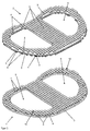
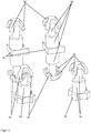
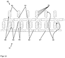
- FIGS. 1 to 5 show a first embodiment of the present invention, shows FIG. 1 a schematic perspective view of a cage according to the invention, which is composed of five plates 1, 2 of a kit according to the invention, FIG. 2 a schematic perspective view of two of the plates 1, 2 after FIG. 1 that are not locked together, FIG. 3 a schematic cross-sectional view through the five latched plates 1, 2 of the cage after FIG. 1 .
- FIG. 4 an enlarged view of a schematic cross-sectional view through the five latched plates 1, 2 of the cage after FIG. 1 and FIG. 5 a schematic cross-sectional view through the two non-latched plates after FIG. 2 ,
- the kit has at least two outer plates 1 intended for attachment to back vertebral bodies (not shown) and has a plurality of central or inner plates 2 which can be inserted between the outer plates 1 to adjust the height of the cage ,
- the plates 1, 2 are made of an elastic biocompatible plastic or stainless steel, titanium, a titanium alloy, tantalum, a tantalum alloy can also be made of composites of these materials.
- the plates 1, 2 are using a CAM method (CAM - Computer-Aided Manufacturing, German: computer-aided manufacturing) or a 3D printing process produced, for example, with selective laser melting SLM (Selective Laser Melting).
- FLM Fused Layer Modeling / Manufacturing
- FDM Fused Deposition Modeling
- LLM Layer Laminated Manufacturing
- EBM Electron Beam Melting
- MLM Multi Jet Modeling
- SLS Selective Laser Sintering
- STL or SLA Stereolithography
- STL or SLA Stereolithography
- DLP Digital Light Processing
- the plates 1, 2 each have a plate-shaped sheet 3, which carries the entire plates 1, 2 and connects in itself.
- the sheet 3 may be flexible and elastically deformable to a limited extent, so that other surfaces can be formed as planes with the sheet 3, so that the plates 1, 2 can be adapted to a small extent to the shape of the vertebral bodies.
- Of the fabrics 3 extend in each plate 1, 2 a plurality of pins 4 away, which protrude perpendicularly from the plane of the sheet 3.
- FIGS. 1 to 5 two different types of plates 1, 2 are shown, namely outer plates 1, which have a flat underside and in which the pins 4 extend from the sheet 3 only on one side of the sheets 3, and secondly, middle plates 2 and inner plates 2, respectively in which the pins 4 extend from both sides of the sheet 3 from.
- outer plates 1 which have a flat underside and in which the pins 4 extend from the sheet 3 only on one side of the sheets 3, and secondly, middle plates 2 and inner plates 2, respectively in which the pins 4 extend from both sides of the sheet 3 from.
- the plates 1, 2 are sandwiched to each other, wherein the outer plates 1 form the two top surfaces and the inner plates 2 are arranged between the outer plates 1.
- the outer plates 1 can be attached over a large area adjacent to the vertebrae to be treated.
- eyelets may be provided in the sheet 3, so that the outer plates 1 can be screwed onto the vertebral bodies, or on the side of the sheet 3 without pins 4 tips (not shown) may be provided in the Bones of the vertebral bodies are inserted.
- the inner plates 2 can However, theoretically also be attached to the vertebral bodies to be treated, albeit with a smaller contact surface, so that theoretically can be dispensed with the outer plates 1.
- mushrooms 5 are provided as latching elements 5 at the opposite ends of the sheets 3 of the pins.
- the mushrooms 5 are rounded outward (away from the sheet 3) and form spherical sections. But there are also other rounding, such as elliptical sections possible.
- the mushrooms 5 On the side facing the fabric 3 side, the mushrooms 5 form a flat gripping surface, which are suitable for catching and catching with other mushrooms 5 engaging plates 1, 2.
- the pins 4 are also provided adjacent to the mushrooms 5 and the gripping surfaces grooves 6 as a counter-locking means 6, in which the mushrooms 5 adjacent plates 1, 2 engage or can engage.
- the edges of the grooves 6 facing the fabric 3 are rounded so that the mushrooms 5 fit or snap well into the grooves 6.
- the shape of the grooves 6 corresponds to a negative of the shape of the surface of the mushrooms 5, so that they can rest along a line in one of the grooves 6.
- the mushrooms 5 thus form locking elements 5 and the grooves 6 the matching counter-locking means 6. Further insertion of the plate 1, 2 after the detent is prevented by this structure.
- FIGS. 3 and 4 show a schematic cross-sectional view on the fungi 5 latched together plates 1, 2 of the kit according to the invention.
- the pins 4 with the mushrooms 5 can be arranged in groups or islands of pins 4 or mushrooms 5 (in FIGS FIGS. 1 to 5 Not shown). As a result, the pins 4 arranged at the edge of the groups or islands can more easily bend outward when the mushrooms 5 of another plate 1, 2 are pressed open. As a result, the plates 1, 2 are easier to connect to each other, since the elastic deformations of the pins 4 when locking the mushrooms 5 in the grooves 6 do not interfere with each other.
- the plates 1, 2 preferably abut one another, but are not hooked or latched with one another, so that the mushrooms 5 of the pins 4 of adjacent plates 1, 2 do not mesh with each other yet.
- the plates 1, 2 may be wetted with a liquid.
- the liquid preferably contains at least one pharmaceutically active substance which is suitable for controlling an infection or for stimulating bone growth.
- the plates 1, 2 may be coated with such a pharmaceutically active substance.
- the cage can be formed by pressing the plates 1, 2 over their surfaces. As a result, the plates 1, 2 latch together and the cage is solidified in the desired shape. Before or during this, the plates 1, 2 can also be deformed by a slight elastic deformation of the fabric 3 and adapted to the treatment situation. After latching with at least one further (usually then also deformed) inner plate 2, the two so interconnected plates 1, 2 stabilize each other, so that the selected shape is solidified.
- the plates 1, 2 can rest with each other by the mushrooms 5 elastically deform the pins 4 connected plates 1, 2 and push through the elastic restoring force of the pins 4, the mushrooms 5 and the edges of the mushrooms 5 in the grooves 6 and thereby the Limit movement of adjacent plates 1, 2 away from the sheet 3 (see Figures 3 and 4 ).
- the adapted shape of the grooves 6 to the mushrooms 5 further movement of the mushrooms 5 is blocked, especially when a large number of mushrooms 5 is engaged in a large number of grooves 6.
- the dimensions of the mushrooms 5, the thickness of the sheet 3, the shape of the grooves 6 and the length of the pins 4 between the sheet 3 and the mushrooms 5 are coordinated so that when connecting the plates 1, 2 of the sheet 3 facing away surfaces of the mushrooms 5 on the surface of the grooves 6 adjacent plates 1, 2 and / or rest when connecting the plates 1, 2, the gripping surfaces of the mushrooms 5 in the gripping surfaces of the mushrooms 5 of the adjacent plate 1, 2.
- the grooves 6 also prevent the gripping surfaces or the opposite cap tops of the mushrooms 5 completely cover the pores 7. So that the recesses 7 can be covered even worse by the mushrooms 5, the recesses 7 may have a plurality of slots (not shown) which are distributed over the circumference of the recesses 7.
- the finished cage has two open axial cavities 8, which arise by superimposing the plates 1, 2, in which matching recesses 9 are present.
- the open axial cavities 8 and thus the recesses 9 serve to allow bone of the vertebral body to grow through them.
- the surfaces of the open axial cavities 8 and the recesses 9 are filled with autologous bone substitute material and, if desired, additionally coated with a bone growth promoting substance.
- the free cross section of the recesses 9 and the open axial cavities 8 is about 10 mm but at least 5 mm, so that the bone of the vertebral body can grow well.
- the open axial cavities 8 thus form the interior of the cage.
- the open axial cavities 8 are uniform and the outer shape of the cage is flat, the plates 1, 2 must be aligned or matched to each other.
- four positioning pins 10 are provided as positioning aids 10 on the fabrics 3 of the outer plates 1.
- the inner plates 2 for this purpose four matching holes in the fabrics 3, so that the positioning pins 10 are inserted when resting the plates 1, 2 through these holes and thus specify the orientation and position of the inner plate 2 relative to the outer plate 1. In this way it can be ensured that the plates 1, 2 are placed flush with one another or fitting one another.
- the plates 1, 2 all have the same shape with respect to the plane of the sheets 3, so that they can be placed on each other fittingly. In the in the FIGS.
- the length of the positioning pins 10 is just chosen so that it only extends through the bore of the adjacent plate 2. It would be readily possible to provide longer positioning pins 10 through the holes more Plates 1, 2 is enough. Likewise, the positioning pins 10 could also be provided on an inner plate 2 and provided in the outer plates 1 holes. The positioning pins 10 could then also terminate in tips which are inserted into the vertebral body and secured therein. Likewise, in this variant (not shown), the positioning pins 10 may extend perpendicularly from the sheet in both directions.
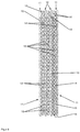
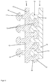
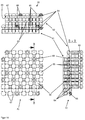
- FIGS. 6 to 12 show a second embodiment of the present invention, shows FIG. 6 a schematic perspective view of a second cage according to the invention, which is composed of four plates 11, 12 of a second kit according to the invention, FIG. 7 a schematic perspective view of the cage according to FIG. 6 in the condition used in the patient, FIG. 8 a schematic cross-sectional view through the four latched plates 11, 12 of the cage after FIG. 6 .
- FIG. 9 an enlarged view of a schematic cross-sectional view through two latched plates 11, 12 of the kit after the FIGS. 6 to 8 .
- FIG. 10 a schematic perspective view of an outer plate 11 according to one of FIGS. 6 to 9 .
- FIG. 11 an enlargement of a partial area A in FIG. 10
- FIG. 12 a schematic perspective view of one of the inner plates 12 according to one of FIGS. 6 to 9 ,
- the kit has at least two outer plates 11 adapted for attachment to back vertebral bodies 17 (see Figs FIG. 7 ) and has a plurality of central or inner plates 12 which can be inserted between the outer plates 11 to adjust the height of the cage.
- the plates 11, 12 are made of an elastic biocompatible plastic or stainless steel, titanium, a titanium alloy, tantalum, a tantalum alloy can also be made of composites of these materials.
- the plates 11, 12 are produced with a CAM (Computer Aided Manufacturing) method or a 3D printing method, for example with selective laser melting SLM (Selective Laser Melting).
- FLM Fused Layer Modeling / Manufacturing
- FDM Fused Deposition Modeling
- LLM Layer Laminated Manufacturing
- EBM Electron Beam Melting
- MLM Multi Jet Modeling
- SLS Selective Laser Sintering
- STL or SLA Stereolithography
- STL or SLA Stereolithography
- STL or SLA Stereolithography
- the plates 11, 12 each have a plate-shaped sheet 13 which carries the entire plates 11, 12 and connects to each other.
- the sheet 13 may be flexible and elastically deformable to a limited extent, so that other surfaces than planes can be formed with the sheet 13, so that the plates 11, 12 can be adapted to a small extent to the shape of the vertebral body 17.
- each plate 11, 12 has a plurality of pins 14 extending perpendicularly from the plane of the sheets 13.
- FIGS. 6 to 12 Two different types of plates 11, 12 are shown, namely outer plates 11, which have a flat underside and in which the pins 14 extend from the sheet 13 only on one side of the sheets 13, and secondly, middle plates 12 and inner plates 12, respectively in which the pins 14 extend from both sides of the sheet 13.
- outer plates 11 For a fully assembled cage (see FIGS. 6 . 7 and 8th ), the plates 11, 12 are sandwiched with each other, the outer plates 11 forming the two top surfaces and the inner plates 12 are disposed between the outer plates 11.
- the outer plates 11 can be attached over a large area adjacent to the vertebral bodies 17 to be treated.
- eyelets may be provided in the sheet 13, so that the outer plates 11 can be screwed onto the vertebral bodies 17, or on the side of the sheet 13 without pins 14 tips (not shown) may be provided, which in the bones of the vertebral bodies 17 are inserted.
- the inner plates 12 can theoretically also be fastened on the vertebral bodies to be treated, albeit with a smaller contact surface, so that theoretically the outer plates 11 can be dispensed with.
- mushrooms 15 are provided as latching elements 15 at the sheet 13 opposite ends of the pins.
- the mushrooms 15 are rounded outward (away from the sheet 13) and form ball sections. But there are also other rounding, such as elliptical sections possible.
- the mushrooms 15 form a flat gripping surface which is suitable for catching and resting with other mushrooms 15 of engaging plates 11, 12.
- the pins 14 are also provided adjacent to the mushrooms 15 and the gripping surfaces grooves 16 as counter-locking means 16, in which the mushrooms 15 adjacent plates 11, 12 engage or can engage.
- the edges of the grooves 16 facing the fabric 13 are rounded so that the mushrooms 15 fit or snap well into the grooves 16.
- the shape of the grooves 16 corresponds to a negative of the shape of the surface of the mushrooms 15, so that they can rest along a line in one of the grooves 16.
- the mushrooms 15 thus form latching elements 15 and the grooves 16 the matching counter-latching means 16. Further insertion of the plate 11, 12 after latching is prevented by this structure.
- FIGS. 8 and 9 show a schematic cross-sectional view on the mushrooms 15 with each other latched plates 11, 12 of the kit according to the invention.
- the sheet 13 unlike the first embodiment, no pores are arranged.
- the pins 14 with the mushrooms 15 can be arranged in groups or islands of pins 14 or mushrooms 15 (in FIGS FIGS. 1 to 5 Not shown). As a result, the pins 14 arranged at the edge of the groups or islands can bend more easily outwards when the mushrooms 15 of another plate 11, 12 are pressed open. As a result, the plates 11, 12 are easier to connect to each other, since the elastic deformations of the pins 14 do not interfere with each other when the mushrooms 15 engage in the grooves 16.
- the plates 11, 12 preferably abut one another, but are not hooked or latched with one another, so that the mushrooms 15 of the pins 14 of adjacent plates 11, 12 do not mesh with each other yet.
- the plates 11, 12 may be wetted with a liquid.
- the liquid preferably contains at least one pharmaceutically active substance which is suitable for controlling an infection or for stimulating bone growth.
- the plates 11, 12 may be coated with such a pharmaceutically active substance.
- the cage can be formed by pressing the plates 11, 12 together over their surfaces. As a result, the plates 11, 12 snap together and the cage is solidified in the desired shape. Before or during this, the plates 11, 12 can also be deformed by a slight elastic deformation of the fabric 13 and adapted to the treatment situation. After latching with at least one other (usually then also deformed) inner plate 12, the two so interconnected plates 11, 12 stabilize each other, so that the selected shape is solidified.
- the plates 11, 12 can engage with each other by the mushrooms 15 elastically deform the pins 14 of the connected plates 11, 12 and press the mushrooms 15 and the edges of the mushrooms 15 in the grooves 16 and thus the elastic restoring force of the pins 14 Limit movement of adjacent plates 11, 12 away from the sheet 13 (see FIGS. 8 and 9 ).
- the adapted shape of the grooves 16 to the mushrooms 15 further movement of the mushrooms 15 is blocked, especially when a large number of mushrooms 15 is engaged in a large number of grooves 16.
- the dimensions of the mushrooms 15, the thickness of the sheet 13, the shape of the grooves 16 and the length of the pins 14 between the sheet 13 and the mushrooms 15 are coordinated so that when joining the plates 11, 12 of the sheet 13 facing away from surfaces of the mushrooms 15 abut the surface of the grooves 16 adjacent plates 11, 12 and / or in a connection of the plates 11, 12 abut the gripping surfaces of the mushrooms 15 in the gripping surfaces of the mushrooms 15 of the adjacent plate 11, 12. This ensures that the joined plates 11, 12 are not or not without great force against each other are movable.
- the finished cage has two open axial cavities 18, which arise by superimposing the plates 11, 12, in which matching recesses 19 are present.
- the open axial cavities 18 and thus the recesses 19 serve to allow bone of the vertebral body 17 to grow through them.
- the surfaces of the open axial cavities 18 and the recesses 19 are filled with autologous bone substitute material and, if desired, additionally coated with a bone growth promoting substance.
- the free cross section of the recesses 19 and the open axial cavities 18 is about 12 mm but at least 5 mm, so that the bone of the vertebral body can grow well.
- the open axial cavities 18 thus form the interior of the cage.
- the open axial cavities 18 are uniform and the outer shape of the cage is flat, the plates 11, 12 must be aligned or matched to each other.
- positioning pins (not shown) could be provided as positioning aids analogously to the first exemplary embodiment.
- the plates 11, 12 all have the same shape with respect to the plane of the sheets 13, so that they can be placed on each other fittingly.
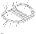
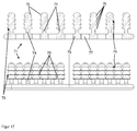
- FIG. 13 shows a schematic side view of five mutually toothed plates 21, 22, which form a third cage according to the invention.
- the cage is designed analogously to one of the first two embodiments.
- outer circumferential edges 27 are provided on the fabrics (in FIG. 13 not seen) of the outer plates 21 and the inner plates 22 .
- the edges 27 abut each other when the plates 21, 22 are locked together.
- the cage is closed to the outside, so that autologous bone material from the interior of the cage can not escape to the outside.
- the cage can be made porous through pores in the plates 21, 22 inside, so that a good through-growth with bone is possible, without that materials can get out of the interior of the cage to the outside.
- FIG. 14 shows a schematic perspective detail view of two hooked hook 55 (left) two hooks 55 not hooked together (right) as parts of plates of a fourth kit according to the invention.
- hooks 55 are provided as latching elements 55 at the opposite ends of the sheets 53.
- the hooks 55 are rounded outwardly (away from the sheet 53) and form parts of spherical surfaces. But there are other rounding as well For example, elliptical sections possible.
- the hooks 55 form undercuts which are suitable for hooking or snapping with other hooks 55 of engaging plates.
- the pins 54 are formed in the area adjacent to the hooks 55 and the undercuts of the hooks 55 thinner or with a smaller cross-section (as grooves). In the thinner areas, the hooks 55 adjacent plates can easily engage or snap.
- the plates are adjacent to each other but not hooked or latched used, so that the hooks 55 of the pins 54 adjacent plates not mesh yet.
- the plates may be wetted with a liquid.
- the liquid preferably contains at least one pharmaceutically active substance which is suitable for controlling an infection or for stimulating bone growth.
- the plates may be coated with such a pharmaceutically active substance.
- the cage can be formed by pressing the plates together over their surfaces. As a result, the plates snag or snap together and the cage is solidified in the desired shape.
- the plates connect to each other in such a way that free spaces between the interconnected plates in the region of the pins 54 and the hook 55 remain so that the cage formed from the plates is open-pored in the directions parallel to the plane of the plates.
- the plates have a cross section or a thickness of about 5 mm, so that the remaining pores have a free cross section in the range of about 0.5 mm. This cross section is sufficient so that bone material can form or grow in the pores.
- the cage with its open pores can therefore be called osteoconductive.
- the cage formed from the plates is therefore well suited for connection to the vertebral bodies.
- the panels should be pressed tightly together so that the cage is dimensionally stable.
- the plates can thereby engage in a first stage with each other by the hooks 55 elastically deform the pins 54 connected plates and the elastic restoring force of the pins 54, the hooks 55 and tips of the hooks 55th press each other and thereby limit the movement of adjacent plates away from the sheet 53. This ensures that the joined plates are not mutually movable without deformation.
- the fourth embodiment according to FIG. 14 So it differs from the after the FIGS. 1 to 12 especially in that hooks 55 are provided as locking elements 55.
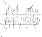
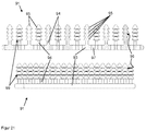
- FIG. 15 shows a schematic perspective view of cutouts of two non-hooked plates 61, 62 of a fifth inventive kit and FIG. 16 three schematic views of the sections of two interconnected plates (acc FIG. 15 ) of the fifth construction kit A) as a top view, B) in a side view, C) in a cross-sectional view along the section BB FIG. 16A) ,
- the plates 61, 62 are made of a biocompatible metal, in particular of stainless steel, titanium or a titanium alloy, tantalum or a tantalum alloy but can also be made of an elastic biocompatible plastic or a composite of such materials.
- the plates 61, 62 are produced by a CAM method and a 3D printing method, for example, with selective electron beam melting (EBM).
- EBM selective electron beam melting
- Other rapid prototyping methods or computer-aided generative manufacturing methods can also be used for the production of the plates 61, 62.
- the plates 61, 62 each have a plate-shaped sheet 63, which carries the entire plates 61, 62 and connects to each other.
- the sheet 63 is elastically deformable, so that other surfaces than planes with the sheet 63 can be formed.
- each plate 61, 62 has a plurality of pins 64 extending perpendicularly from the plane of the sheets 63.
- the pins 64 there are arranged between the pins 64 a plurality of through pores 67 which, when the plates 61, 62 are connected together to form a cage, may cause an open porosity of the cage in a direction perpendicular to the sheets 63, if not the adjacent plates 61, 62 abut and thereby cover the pores 67.
- FIGS. 15 and 16 two different types of plates 61, 62 are shown, namely, first, an outer plate 61 having a flat bottom surface and with the pins 64 extending from the sheet 63 only on one side of the sheets 63, and secondly, inner plates 62 where the pins 64 extend from both sides of the sheet 63.
- the outer plates 61 are in FIG. 15 below, in FIG. 16A) below (in the picture plane), in FIG. 16 B) down and in Figure 16C) shown on the left.
- the inner plates 62 are in FIG. 15 up and in FIG. 16 on top, so in FIG. 16A) above (from the image plane), in FIG. 16 B) up and in Figure 16C) shown on the right.
- the outer plates 61 can be attached over a large area on the vertebral bodies to be treated (not shown). However, the inner plates 62 may also be mounted on the vertebral bodies to be treated, albeit with a smaller contact surface, so that the outer plates 61 can theoretically be dispensed with.
- mushrooms 65 or groups of four hooks 68 are provided as latching elements 65, 68 at the opposite ends of the fabrics 63 opposite ends.
- the mushrooms 65 are rounded outward (away from the sheet 63) and form ball sections. But there are also other rounding, such as elliptical sections possible.
- the hooks 68 are rounded in the same way to the outside.
- the mushrooms 65 form a flat gripping surface 69 suitable for hooking or catching with other mushrooms 65 and hooks 68 of engaging plates 61, 62. Accordingly, the hooks 68 on the side facing the sheet 63 side undercuts, which are suitable for hooking and snapping with other mushrooms 65 and hook 68 engaging plates 61, 62.
- the pins 64 are also provided adjacent to the gripping surfaces 69 and adjacent to the hooks 68 grooves 66 as a counter-latching means 66, in which the mushrooms 65 and hooks 68 adjacent plates 61, 62 engage or engage.
- the grooves 66 in contrast to the grooves 66 shown, but preferred according to the invention, as a negative of the shape of the curvature of the mushrooms 65 and the hook 68 may be formed (analogous to the first two embodiments), so that the mushrooms 65 and hooks 68 well into the Grooves 66 fit.
- mushrooms 65 and hooks 68 are mixedly provided as latching elements 65, 68 on the plates 61, 62, two of eleven latching elements 65, 68 being hooks 68 and the remainder being mushrooms 65. This may also be the other way around and the hooks 68 and mushrooms 65 may also be present in a different mixing ratio.
- the plates 61, 62 abut each other but not hooked or latched before (ie not as in FIG. 16 ), so that the mushrooms 65 and hooks 68 of the pins 64 of adjacent plates 61, 62 do not mesh with each other yet.
- the plates 61, 62 may be wetted with a liquid.
- the liquid preferably contains at least one pharmaceutically active substance, in particular an autologous bone substance.
- the plates may be coated with such a pharmaceutically active substance.
- the cage can be formed by pressing the plates 61, 62 together over their surfaces. As a result, the plates 61, 62 engage and snap together and the cage is solidified in the desired shape.
- the plates 61, 62 can also be deformed by elastic deformation of the fabric 63 and adapted to the treatment situation. After hooking or catching with at least one further plate 61, 62, the two plates 61, 62 connected to one another stabilize one another, so that the selected shape is solidified.
- the plates 61, 62 connect to each other in such a way that free spaces between the interconnected plates 61, 62 in the region of the pins 64, the mushroom 65, the hook 68 and the grooves 66 remain so that the out of the plates 61st 62 formed cages in the directions parallel to the plane of the plates 61, 62 is open-pored.
- the plates 61, 62 have a cross section or a thickness of about 9 mm, so that the remaining pores 67 have a free cross section in the range of about 0.9 mm. This cross section is sufficient so that bone material can form or grow in the pores 67.
- the cage with its open pores 67 can therefore be called osteoconductive.
- the cage formed from the plates 61, 62 is therefore well suited for connection to the bone of the vertebral bodies.
- the plates 61, 62 should be firmly pressed together so that the cage is dimensionally stable.
- the plates 61, 62 can engage with each other by the mushrooms 65 and hooks 68 elastically deform the pins 64 connected plates 61, 62 and by the elastic restoring force of the pins 64, the mushrooms 65 and hooks 68 and the edges of the mushrooms 65 and tips the hook 68 press into the grooves 66 and thereby limit the movement of adjacent plates 61, 62 away from the sheet 63 (see FIG FIG. 16 ). It is also possible that, firstly, the edges of the mushrooms 65 and / or the tips of the hooks 68 plastically deform the pins 64, the grooves 66 or the mushrooms 65 to a small extent, thereby locking the plates 61, 62 together.
- the dimensions of the mushrooms 65, the hooks 68, the thickness of the sheet 63, the shape of the grooves 66 and the length of the pins 64 between the sheet 63 and the mushrooms 65 or hooks 68 are matched to one another such that when the sheets are joined 61, 62 abuts the surfaces of the mushrooms 65 and hooks 68 facing away from the fabric 63 on the surface of the sheets 63 of adjacent sheets 61, 62 and / or in joining the sheets 61, 62 the surfaces of the mushrooms 65 and 62 facing away from the sheet 63 Hook 68 on the gripping surface 69 of the mushrooms 65 and preferably along at least one line or more preferably flat against the grooves 66 of the pins 64 of the adjacent plate 61, 62. This ensures that the joined plates 61, 62 are not mutually movable without deformation.
- the fifth embodiment according to FIGS. 15 and 16 So it differs from the after the FIGS. 1 to 5 especially in that hooks 68 are provided as locking elements 68.
- FIG. 17 shows a schematic cross-sectional view through an outer plate of a sixth kit according to the invention ( FIG. 17 above) and a schematic side view of the outer plate of the sixth kit ( FIG. 17 below).
- FIG. 18 shows an enlarged view of a schematic cross-sectional view through two ratcheted plates of the sixth kit after FIG. 17 ,
- FIG. 19 shows a schematic cross-sectional view through an outer plate of a seventh kit according to the invention ( FIG. 19 above) and a schematic side view of the outer plate of the seventh kit ( FIG. 19 below).
- FIG. 20 shows an enlarged view of a schematic cross-sectional view through two ratcheted plates of the seventh kit after FIG. 19 ,
- FIG. 21 shows a schematic cross-sectional view through an outer plate of an eighth kit according to the invention ( FIG. 21 above) and a schematic side view of the outer plate of the eighth kit ( FIG. 21 below).
- FIG. 22 shows an enlarged view of a schematic cross-sectional view through two ratcheted plates of the eighth kit after FIG. 21 ,
- kits each have at least two outer plates 71, 81, 91 provided for attachment to dorsal vertebral bodies, and each have a plurality of central or inner plates 72, 82, 92 disposed between the outer plates 71, 81, 91 can be used to adjust the height of the cage.
- the plates 71, 72, 81, 82, 91, 92 are made of an elastic biocompatible plastic or stainless steel, titanium, a titanium alloy, tantalum, a tantalum alloy but can also be made of composites of these materials.
- the plates 71, 72, 81, 82, 91, 92 are produced using a CAM (Computer Aided Manufacturing) method or a 3D printing method, for example selective SLM (Selective Laser Melting ).
- FLM Fused Layer Modeling / Manufacturing
- FDM Fused Deposition Modeling
- LLM Layer Laminated Manufacturing
- EBM Electron Beam Melting
- MJM Multi Jet Modeling
- SLS Selective Laser Sintering
- STL or SLA Stereolithography
- DLP digital light processing
- the plates 71, 72, 81, 82, 91, 92 each have a plate-shaped sheet 73, 83, 93, which carries the entire plates 71, 72, 81, 82, 91, 92 and connects to each other.
- the fabric 73, 83, 93 may be flexible and elastically deformable to a limited extent, so that other surfaces than planes with the Sheet 73, 83, 93 can be formed so that the plates 71, 72, 81, 82, 91, 92 can be adapted to a small extent to the shape of the vertebral bodies.
- each plate 71, 72, 81, 82, 91, 92 has a plurality of pins 74, 84, 94 extending perpendicularly from the plane of the sheets 73, 83, 93.
- FIGS. 17 to 22 For example, two different types of plates 71, 72, 81, 82, 91, 92 are shown, namely outer plates 71, 81, 91, which have a flat underside and in which the pins 74, 84, 94 are only on one side of the sheets 73, 83, 93 extend from the sheet 73, 83, 93, and secondly, middle plates 72, 82, 92 and inner plates 72, 82, 92, respectively, in which the pins 74, 84, 94 extend from both sides of the sheet 73 , 83, 93 extend out.
- a finished cage or assembled or mated plates 71, 72, 81, 82, 91, 92 see Figures 18 .
- the plates 71, 72, 81, 82, 91, 92 are sandwiched to each other, wherein the outer plates 71, 81, 91 form the two cover surfaces and the inner plates 72, 82, 92 between the outer plates 71, 81, 91 are arranged.
- the outer plates 71, 81, 91 can be attached over a large area adjacent to the vertebral bodies to be treated.
- eyelets may be provided in the sheet 73, 83, 93, so that the outer plates 71, 81, 91 can be screwed onto the vertebral bodies or on the side of the sheet 73, 83, 93 without pins 74, 84, 94 provided with tips (not shown) which can be inserted into the bones of the vertebral bodies.
- the inner plates 72, 82, 92 can theoretically also be fastened on the vertebral bodies to be treated, albeit with a smaller contact surface, so that theoretically the outer plates 71, 81, 91 can be dispensed with.
- mushrooms 75, 85, 95 per pin 74, 84, 94 are provided as latching elements 75, 85, 95.
- the mushrooms 75, 85, 95 at the tips of the pins 74, 84, 94 are rounded outwardly (away from the sheet 73, 83, 93).
- the mushrooms 75, 85 at the tips of the pins 74, 84 ball sections while in the eleventh embodiment, the mushrooms 95 are made somewhat sharper at the tips of the pins 94. But there are also other rounding, such as elliptical sections possible.
- the mushrooms 75, 85, 95 which are arranged below the mushrooms 75, 85, 95 at the tip of the pins 74, 84, 94, that is on the pins 74, 84, 94 between the fabric 73, 83, 93 and the mushrooms 75, 85, 95 which are arranged on the side facing away from the sheet 73, 83, 93 side of the pins 74, 84, 94, have the shape of a truncated cone or are blunt-conical.
- the mushrooms 75, 85, 95 form a flat gripping surface 79, 89, 99, for engaging with other mushrooms 75, 85, 95 engaging plates or with recesses 76, 86th , 96 engaging plates are suitable.
- the pins 94 and mushrooms 95 of the eighth embodiment ( Figures 21 and 22 ) have a slightly smaller diameter than that of the sixth and seventh embodiments, wherein the gripping surfaces 99 of the eighth embodiment are designed somewhat deeper or larger than the gripping surfaces 79, 89 of the sixth and seventh embodiment.
- Another insertion of the plates 71, 72, 81, 82, 91, 92 is in the sixth, seventh and eighth embodiments, by pressing the pins 74, 84, 94 with the mushrooms 75, 85, 95 into and through the recesses 73, 83, 93, respectively.
- the Figures 18 . 20 and 22 show a schematic cross-sectional view on the fungi 75, 85, 95 interlocked plates 71, 72, 81, 82, 91, 92 of the kits according to the invention.
- a plurality of through pores 77, 87, 97 are disposed between the pins 74, 84, 94.
- the pores 77, 87, 97 cause an open porosity of the cage on the support surface to the vertebral body in a direction perpendicular to the sheets 73, 83, 93 effect.
- the bones of the vertebral bodies more easily grow together with the outer plates 71, 81, 91 of the cage.
- the pins 74, 84, 94 are thinnest between the mushrooms 75, 85, 95 and the sheets 73, 83, 93, so that the pins 74, 84, 94 are the lightest in the area of connection to the sheets 73, 83, 93 can be bent, or there are the most mobile to the latching process or the Hooking the mushrooms 75, 85, 95 with the grooves 76, 86, 96 between the mushrooms 75, 85, 95 to allow.
- the plates 71, 72, 81, 82, 91, 92 preferably abut one another, but are not hooked or latched with each other, so that the mushrooms 75, 85, 95 of the pins 74, 84, 94 of adjacent plates 71, 72, 81, 82, 91, 92 are not yet interlocking.
- the plates 71, 72, 81, 82, 91, 92 may be wetted with a liquid.
- the liquid preferably contains at least one pharmaceutically active substance which is suitable for controlling an infection or for stimulating bone growth.
- the plates 71, 72, 81, 82, 91, 92 may be coated with such a pharmaceutically active substance.
- the cage can be formed by pressing the plates 71, 72, 81, 82, 91, 92 together over their surfaces. As a result, the plates 71, 72, 81, 82, 91, 92 snap together and the cage is solidified in the desired shape. Before or during this, the plates 71, 72, 81, 82, 91, 92 can also be deformed by slight elastic deformation of the fabrics 73, 83, 93 and adapted to the treatment situation. After latching with at least one further (usually then also deformed) inner plate 72, 82, 92 stabilize the two so interconnected plates 71, 72, 81, 82, 91, 92 each other, so that the selected shape is solidified.
- the plates 71, 72, 81, 82, 91, 92 can engage with each other by the mushrooms 75, 85, 95, the pins 74, 84, 94 of connected plates 71, 72, 81, 82, 91, 92 elastically deform and by the elastic restoring force of the pins 74, 84, 94, the mushrooms 75, 85, 95 and the edges of the mushrooms 75, 85, 95 in the grooves 76, 86, 96 press and thereby the movement of adjacent plates 71, 72, 81, 82nd , 91, 92 of the sheet 73, 83, 93 limit away (see Figures 18 . 20 and 22 ).
- the plates 71, 72, 81, 82, 91, 92 connect to each other in such a way that free spaces between the interconnected plates 71, 72, 81, 82, 91, 92 in the region of the pins 74, 84, 94, the mushrooms 75, 85, 95 and the grooves 76, 86, 96 remain, so that the cages formed from the plates 71, 72, 81, 82, 91, 92 in the directions parallel to the plane of the plates 71, 72, 81, 82, 91, 92 is open-pored.
- the plates 71, 72, 81, 82, 91, 92 have a cross section or a thickness between 0.25 mm and 1.5 mm.
- This cross-section is sufficient to get into the Pores 77, 87, 97 and between the plates 71, 72, 81, 82, 91, 92 can form bone or ingrowth.
- the cage with its open pores 77, 87, 97 can therefore be called osteoconductive.
- the cage formed from the plates 71, 72, 81, 82, 91, 92 is therefore well suited for connection to the bone of the vertebral bodies.
- the finished cage has two open axial cavities (not shown), which arise by superimposing the plates 71, 72, 81, 82, 91, 92, in which matching recesses are present, but in the FIGS. 17 to 22 not to be seen.
- the axial cavities and the recesses are constructed analogously to the preceding embodiments.
- the open axial cavities and thus the recesses also serve to ensure that the bones of the vertebral body can grow through them.
- the surfaces of the open axial cavities and the recesses are filled with autologous bone substitute material and, if desired, additionally coated with a bone growth promoting substance.
- the free cross section of the recesses and the open axial cavities is about 12 mm but at least 5 mm, so that the bone of the vertebral body can grow well.
- the open axial cavities thus form the interior of the cage.
- the open axial cavities are uniform and the outer shape of the cage is flat, the plates 71, 72, 81, 82, 91, 92 must be aligned or mating with each other.
- positioning pins (not shown) could be provided as positioning aids analogously to the first exemplary embodiment.
- the plates 71, 72, 81, 82, 91, 92 all have the same shape with respect to the plane of the sheets 73, 83, 93, so that they can be placed on each other fittingly.
- kits of all embodiments may also include more than the plates shown and also include plate groups with different geometries to make the kits as variable as possible and to make them usable for the treatment of different anatomical conditions.
Abstract
Die Erfindung betrifft einen modularen Bausatz zur Herstellung eines Käfigs für die Spondylodese, der Bausatz aufweisend zumindest zwei Platten (1, 2), wobei die Platten (1, 2) aus einem biokompatiblen Material bestehen und jeweils ein Flächengebilde (3) aufweisen und eine Mehrzahl von sich aus dem Flächengebilde (3) der Platten (1, 2) heraus erstreckende Stifte (4) aufweisen, wobei die Stifte (4) jeweils mindestens ein Rastelement (5) aufweisen, wobei die Stifte (4) elastisch verformbar sind und auf dem Flächengebilde (3) derart dicht nebeneinander angeordnet sind, so dass durch Aufeinanderpressen von mit Stiften (4) besetzten Flächengebilden (3) mehrerer Platten (1, 2) die Rastelemente (5) verschiedener Platten (1, 2) miteinander rasten, wobei zumindest zwei der zumindest zwei Platten (1, 2) eine Ausnehmung (9) mit einem Durchmesser von wenigstens 5 mm aufweisen. Die Erfindung betrifft auch ein Verfahren zum Herstellen eines Käfigs für die Spondylodese mit einem solchen Bausatz, bei dem mehrere Platten (1, 2) gegeneinander gedrückt werden, wobei die Platten (1, 2) miteinander rasten und den Käfig ausbilden. Ferner betrifft die Erfindung einen Käfig für die Spondylodese aufgebaut aus zumindest zwei Platten (1, 2).The invention relates to a modular kit for producing a cage for the spinal fusion, the kit comprising at least two plates (1, 2), wherein the plates (1, 2) consist of a biocompatible material and each having a sheet (3) and a plurality by itself from the sheet (3) of the plates (1, 2) out extending pins (4), wherein the pins (4) each have at least one latching element (5), wherein the pins (4) are elastically deformable and on the Sheet (3) are arranged so close together, so that by pressing together with pins (4) occupied sheets (3) of several plates (1, 2) the locking elements (5) of different plates (1, 2) snap together, at least two the at least two plates (1, 2) have a recess (9) with a diameter of at least 5 mm. The invention also relates to a method for producing a cage for the spinal fusion with such a kit, in which a plurality of plates (1, 2) are pressed against each other, wherein the plates (1, 2) engage with each other and form the cage. Furthermore, the invention relates to a cage for spinal fusion constructed from at least two plates (1, 2).
Description
Die Erfindung betrifft einen modularen Bausatz zur Herstellung eines Käfigs für die Spondylodese. Die Erfindung betrifft auch ein Verfahren zur Herstellung eines solchen Käfigs und einen Käfig zur Spondylodese.The invention relates to a modular kit for producing a cage for spinal fusion. The invention also relates to a method for producing such a cage and a cage for spinal fusion.
Gegenstand der Erfindung ist somit auch ein Käfig (häufig im internationalen Sprachgebrauch auch als "Cage" bezeichnet) zur Spondylodese von Wirbelkörpern mit einstellbarer Höhe und ein Verfahren zur Herstellung von Käfigen ("Cages") mit einstellbarer Höhe.The invention thus also relates to a cage (also commonly referred to in international usage as "cage") for the spinal fusion of vertebral bodies with adjustable height and a method for the production of cages with adjustable height.
Die Spondylodese (Wirbelkörperverblockung) wird zur Versteifung von zwei oder mehreren Wirbelkörpern der Hals-, Brust- und Lendenwirbelsäule eingesetzt. Die Spondylodese (Wirbelkörperverblockung) kommt bei instabilen Brüchen von Wirbelkörpern, bei kongenitaler (angeborener) Skoliose und bei Wirbelgleiten zur Anwendung. Dabei werden zwei oder mehrere übereinander liegende Wirbelkörper mit Hilfe von Schrauben, Platten und Stangen miteinander verbunden. In den Zwischenwirbelraum werden Käfige (Cages) eingesetzt, welche die übereinander liegenden Wirbelkörper beabstanden, so dass eine Kompression des Rückenmarks und der davon ausgehenden Nerven vermieden wird. Weiterhin dienen die Käfige der Kraftübertragung zwischen den Wirbelkörpern. Die Käfige enthalten üblicherweise einen offenen axialen Hohlraum. Diese Hohlraum kann zum Beispiel mit Knochenersatzmaterialien, wie Calciumphosphaten, oder auch mit autologer Spongiosa gefüllt werden (Aaron R Cutler A. R., et. Al.: Comparison of polyetheretherketone cages with femoral cortical bone allograft as a single-piece interbody spacer in transforaminal lumbar interbody fusion.
Die Aufgabe der Erfindung besteht also darin, die Nachteile des Stands der Technik zu überwinden. Insbesondere soll ein mechanisch stabiler Käfig für die Spondylodese entwickelt werden, dessen Höhe ohne Verwendung von technischen Hilfsmitteln in einfachster Weise eingestellt werden kann. Der zu entwickelnde Käfig soll keine komplexen Hebel- und/oder Schraubsysteme enthalten. Des Weiteren soll der Käfig möglichst porös sein, um ein eine knöcherne Durchbauung des Käfigs zu gewährleisten. Weiterhin muss der Käfig biokompatibel sein. Der Käfig soll auch einen formstabilen porösen Körper bilden, eine offene Porosität besitzen sowie mechanisch stabil sein. Die Porosität und die Größe der Poren sollen dabei dazu ausreichen und dazu geeignet sein, dass menschlicher Knochen eines Patienten, der mit dem Käfig behandelt wird, in die Poren des Käfigs einwachsen kann.The object of the invention is therefore to overcome the disadvantages of the prior art. In particular, a mechanically stable cage for spinal fusion should be developed, the height of which can be adjusted in the simplest way without the use of technical aids. The cage to be developed should not contain complex lever and / or screw systems. Furthermore, the cage should be as porous as possible to ensure a bony structure of the cage. Furthermore, the cage must be biocompatible. The cage should also form a dimensionally stable porous body, have an open porosity and be mechanically stable. The porosity and size of the pores are said to be sufficient and suitable for the fact that human bone of a patient who is treated with the cage, can grow into the pores of the cage.
Die Aufgaben der Erfindung werden gelöst durch einen modularen Bausatz zur Herstellung eines Käfigs für die Spondylodese, der Bausatz aufweisend zumindest zwei Platten, wobei die Platten aus einem biokompatiblen Material bestehen und jeweils ein Flächengebilde aufweisen und eine Mehrzahl von sich aus dem Flächengebilde der Platten heraus erstreckende Stifte aufweisen, wobei die Stifte jeweils mindestens ein Rastelement aufweisen, wobei die Stifte elastisch verformbar sind und auf dem Flächengebilde derart dicht nebeneinander angeordnet sind, so dass durch Aufeinanderpressen von mit Stiften besetzten Flächengebilden mehrerer Platten die Rastelemente verschiedener Platten miteinander rasten, wobei zumindest zwei der zumindest zwei Platten eine Ausnehmung mit einem Durchmesser von wenigstens 5 mm aufweisen.The objects of the invention are achieved by a modular kit for producing a cage for the spinal fusion, the kit comprising at least two plates, wherein the plates consist of a biocompatible material and each having a sheet and a plurality of extending from the sheet of the plates out Having pins, wherein the pins each have at least one locking element, wherein the pins are elastically deformable and are arranged on the sheet so close to each other, so that by pressing together occupied with pins fabrics of several plates, the locking elements of different plates with each other, wherein at least two of at least two plates have a recess with a diameter of at least 5 mm.
Bevorzugt kann vorgesehen sein, dass die zumindest zwei Platten aus einem biokompatiblen Kunststoff, einem biokompatiblen Metall und/oder einer biokompatiblen Metalllegierung bestehen. Biokompatible Metalle und biokompatible Metalllegierungen werden erfindungsgemäß bevorzugt, um daraus die Platten des Bausatzes herzustellen.It can preferably be provided that the at least two plates consist of a biocompatible plastic, a biocompatible metal and / or a biocompatible metal alloy. Biocompatible metals and biocompatible metal alloys are preferred in the present invention to make the panels of the kit.
Bevorzugt weisen alle der zumindest zwei Platten eine Ausnehmung mit einem Durchmesser von wenigstens 5 mm auf.Preferably, all of the at least two plates have a recess with a diameter of at least 5 mm.
Bei einem Rasten greifen die Rastelemente der Stifte der Platten derart in Rastelemente von Stiften benachbarter Platten, dass die Platten nicht mehr voneinander getrennt werden können aber auch nicht mehr durch weiteres Zusammendrücken der Platten aufeinander zu bewegt werden können. Die Rastelemente können durch Haken, Nuten, Hinterschnitte, Rastungen und/oder Gegenrastungen gebildet werden.When latching the locking elements of the pins of the plates engage in locking elements of pins of adjacent plates so that the plates can not be separated from each other but also can not be moved towards each other by further compression of the plates. The locking elements can be formed by hooks, grooves, undercuts, detents and / or counter-detents.
Unter dem Begriff "flächig" werden plane Körper und von planen Körpern abgeleitete Körper verstanden, die aus jeweils einem geschlossenen oder aus einem perforierten plattenartigen Grundkörper gebildet sind. Perforierte Flächengebilde sind dabei für die mit den Wirbelkörpern zu verbindenden Platten bevorzugt, weil durch diese Perforationen beziehungsweise die durch die Perforation gebildeten Poren Knochengewebe in die Platten einwachsen kann. Ganz besonders vorteilhaft und erfindungsgemäße bevorzugt ist es, wenn neben jedem Stift eine Perforation beziehungsweise eine Pore in der Platte angeordnet ist. Dann bilden sich nach der Rastung von mehreren Platten zwei poröse Grundflächen zur Verbindung mit den Wirbelkörpern, die bei geeigneter Materialwahl, wie zum Beispiel Tantal, osteokonduktiv sind.The term "planar" is understood to mean planar bodies and bodies derived from planar bodies, which are each formed from a closed or perforated plate-like base body. Perforated fabrics are preferred for the plates to be connected to the vertebral bodies, because bone tissue can grow into the plates through these perforations or the pores formed by the perforation. It is particularly advantageous and preferred according to the invention if, next to each pin, a perforation or a pore is arranged in the plate. Then, after the latching of several plates, two porous base surfaces are formed for connection to the vertebral bodies, which, given a suitable choice of material, such as, for example, tantalum, are osteoconductive.
Bei Druckeinwirkung auf die miteinander in Berührung stehenden Platten des Bausatzes bilden diese erfindungsgemäß einen mechanisch stabilen Verbund aus.When pressure is applied to the plates of the kit which are in contact with one another, they form a mechanically stable composite according to the invention.
Bei erfindungsgemäßen Bausätzen kann vorgesehen sein, dass die miteinander gerasteten Platten einen Käfig aus miteinander gerasteten Platten mit zumindest einem offenen axialen Hohlraum bilden, wobei der Hohlraum einen Durchmesser von wenigstens 5 mm hat, wobei bevorzugt die miteinander gerasteten Platten einen Käfig aus miteinander gerasteten Platten mit zwei offenen axialen Hohlräumen bilden, wobei die beiden Hohlräume einen Durchmesser von jeweils wenigstens 5 mm hat.In kits according to the invention it can be provided that the plates latched together form a cage of plates latched together with at least one open axial cavity, wherein the cavity has a diameter of at least 5 mm, preferably with each other latched plates a cage from each other latched plates with form two open axial cavities, wherein the two cavities has a diameter of at least 5 mm.
Hierdurch wird von dem zumindest einen offenen axialen Hohlraum das Innere des Käfigs gebildet. Durch den zumindest einen offenen axialen Hohlraum kann der Knochen durchwachsen, so dass die beiden Wirbelkörper miteinander verwachsen können.As a result, the interior of the cage is formed by the at least one open axial cavity. Through the at least one open axial cavity of the bone can grow through, so that the two vertebral bodies can grow together.
Des Weiteren kann vorgesehen sein, dass jede der zumindest zwei Platten zumindest eine Ausnehmung mit einem Durchmesser von wenigstens 5 mm aufweist, wobei bevorzugt mit den Ausnehmungen der zumindest zwei Platten der zumindest eine offene axiale Hohlraum des aus den Platten gefertigten Käfigs herzustellen ist.Furthermore, it can be provided that each of the at least two plates has at least one recess with a diameter of at least 5 mm, wherein preferably at least one open axial cavity of the cage produced from the plates is to be produced with the recesses of the at least two plates.
Hierdurch können durch aufeinanderlegen und miteinander rasten der zumindest zwei Platten die Ausnehmungen übereinander liegend zueinander angeordnet werden, so dass die übereinander liegenden Ausnehmungen den zumindest einen offenen axialen Hohlraum bilden in die der Knochen von den beiden angrenzenden Wirbelkörpern einwachsen kann.As a result, by superimposing and latching together of the at least two plates, the recesses are arranged one above the other, so that the superimposed recesses form the at least one open axial cavity into which the bone of the two adjacent vertebrae can grow.
Mit der Erfindung wird auch vorgeschlagen, dass die Wandung des zumindest einen offenen axialen Hohlraums eines aus den zumindest zwei gerasteten Platten gebildeten Käfigs und/oder die Begrenzungen der Ausnehmungen der zumindest zwei Platten mit autologem Knochenmaterial gefüllt sind.The invention also proposes that the wall of the at least one open axial cavity of a cage formed from the at least two latched plates and / or the boundaries of the recesses of the at least two plates are filled with autologous bone material.
Hierdurch wird das autologe Knochenwachstum gefördert, so dass die Ausnehmungen beziehungsweise der zumindest eine offene axiale Hohlraum leichter und schneller vom Knochen des Patienten durchwachsen werden können.As a result, the autologous bone growth is promoted, so that the recesses or the at least one open axial cavity can be more easily and faster through the bone of the patient.
Mit einer Weiterbildung wird vorgeschlagen, dass die miteinander gerasteten Platten einen porösen Käfig aus miteinander gerasteten Platten bilden, bevorzugt einen offenporigen Käfig aus miteinander gerasteten Platten bilden.With a further development, it is proposed that the plates latched together form a porous cage made of plates latched together, preferably forming an open-pored cage of plates latched together.
Hierdurch kann der Knochen zumindest bereichsweise in die Poren des aus den Platten geformten Käfigs wachsen. Des Weiteren wird mit der Erfindung vorgeschlagen, dass die Poren des aus mehreren Platten gebildeten offenporigen Käfigs interkonnektierend und osteokonduktiv sind, wobei vorzugsweise die Poren einen freien Querschnitt zwischen 0,1 mm und 1 mm aufweisen, besonders bevorzugt zwischen 0,25 mm und 0,9 mm. Hiermit wird sichergestellt, dass der Knochen gut mit den Poren des aus dem Bausatz gebildeten Käfigs verwachsen kann. Die nach außen weisenden Seitenwände des Käfigs können erfindungsgemäß durch eine geschlossene Wandung abgeschlossen sein. Hierzu kann an den zumindest zwei Platten ein umlaufender Rand vorgesehen sein, der bei Rastung mit einer benachbarten Platte mit dem Rand der benachbarten Platte formschlüssig abschließt und so die geschlossene Wandung bildet.As a result, the bone can grow at least partially into the pores of the cage formed from the plates. Furthermore, it is proposed with the invention that the pores of the open-pored cage formed from a plurality of plates are interconnecting and osteoconductive, wherein preferably the pores have a free cross-section between 0.1 mm and 1 mm, particularly preferably between 0.25 mm and 0, 9 mm. This ensures that the bone can grow well with the pores of the cage formed from the kit. The outwardly facing side walls of the cage can be completed according to the invention by a closed wall. For this purpose, a circumferential edge may be provided on the at least two plates, which in the case of detenting with an adjacent plate forms a positive fit with the edge of the adjacent plate and thus forms the closed wall.
Bei bevorzugten Bausätzen kann erfindungsgemäß vorgesehen sein, dass der modulare Bausatz zur Herstellung eines Käfigs für die Spondylodese eine einstellbare Höhe aufweist und hierzu vorzugsweise zumindest drei Platten aufweist, damit durch die optionale Verwendung einer inneren Platte oder von mehreren inneren Platten verschiedene Höhen einstellbar sind.In preferred kits can be inventively provided that the modular kit for producing a cage for spinal fusion has an adjustable height and this preferably has at least three plates, so that different heights are adjustable by the optional use of an inner plate or a plurality of inner plates.
Hierdurch wird ein besonders leicht aus dem Bausatz mit verschiedenen Höhen aufzubauender Käfig ermöglicht. Der Bausatz ist dadurch für unterschiedliche Patientenanforderungen variabel einsetzbar und an die anatomische Verhältnisse anzupassen.As a result, a particularly easy aufzubauender from the kit with different heights cage is made possible. The kit can therefore be variably used for different patient requirements and adapted to the anatomical conditions.
Bei einer Weiterbildung kann auch vorgesehen sein, dass die zumindest zwei Platten einen abschließenden umlaufenden Rand aufweisen, so dass die miteinander gerasteten Platten einen Käfig mit einer nach außen abgeschlossenen Wandung bilden, wobei vorzugsweise die Ränder ineinander verzahnt sind.In a further development can also be provided that the at least two plates have a final peripheral edge, so that the plates latched together form a cage with an outwardly closed wall, wherein preferably the edges are interlocked.
Hierdurch kann verhindert werden, dass Material aus dem Inneren des hergestellten Käfigs nach außen dringen kann.In this way it can be prevented that material can penetrate from the inside of the cage produced to the outside.
Ferner kann im Rahmen der vorliegenden Erfindung vorgesehen sein, dass zumindest eine Gruppe der zumindest zwei Platten, bevorzugt zumindest eine Gruppe der zumindest vier Platten, bezüglich der Form der Flächengebilde gleichförmig oder im Wesentlichen gleichförmig sind, so dass sich diese in der Richtung senkrecht zu den Flächengebilden formschlüssig aufeinander stapeln und/oder rasten lassen.Furthermore, it can be provided in the context of the present invention that at least one group of the at least two plates, preferably at least one group of the at least four plates, are uniform or substantially uniform with respect to the shape of the sheets, so that they are in the direction perpendicular to the Stack sheet form-fitting onto one another and / or let it rest.
Hierdurch kann mit dem Bausatz ein bezüglich der Höhe variabler aber im Umfang eindeutig geformter Käfig aus dem Bausatz hergestellt werden.As a result, with the kit with respect to the amount of variable but clearly shaped perimeter cage from the kit can be made.
Dabei kann vorgesehen sein, dass zumindest zwei Gruppen der zumindest zwei Platten, bevorzugt zumindest zwei Gruppen der zumindest vier Platten, bezüglich der Form der Flächengebilde gleichförmig oder im Wesentlichen gleichförmig sind, so dass sich diese in der Richtung senkrecht zu den Flächengebilden formschlüssig aufeinander stapeln und/oder rasten lassen, wobei die zumindest zwei Gruppen unterschiedliche Geometrien bezüglich der Ebenen der Flächengebilde aufweisen.It can be provided that at least two groups of the at least two plates, preferably at least two groups of the at least four plates, are uniform or substantially uniform with respect to the shape of the sheets, so that they stack positively in the direction perpendicular to the fabrics and or let rest, wherein the at least two groups have different geometries with respect to the planes of the sheets.
Hierdurch kann mit dem Bausatz eine Mehrzahl verschiedener Käfige für unterschiedliche anatomische Verhältnisse aufgebaut werden.As a result, a plurality of different cages for different anatomical conditions can be constructed with the kit.
Ferner kann vorgesehen sein, dass zumindest zwei äußeren Platten der zumindest zwei Platten, die zum direkten Verbinden mit den Wirbelkörpern vorgesehen sind, durch Poren in den Flächengebilden osteokonduktiv sind und/oder die Flächengebilde eine Befestigungs-Oberfläche ohne Stifte aufweisen, die zum Anlegen an die Wirbelkörper vorgesehen ist, wobei bevorzugt die Befestigungs-Oberfläche Spitzen oder Noppen zum Verbinden der Platten mit dem Knochen der Wirbelkörper aufweist.Furthermore, it can be provided that at least two outer plates of the at least two plates, which are provided for direct connection to the vertebral bodies, are osteoconductive through pores in the fabrics and / or the fabrics have a mounting surface without pins, which can be applied to the Vertebral body is provided, wherein preferably the attachment surface has peaks or knobs for connecting the plates to the bone of the vertebral bodies.
Die Spitzen oder Noppen können in den Knochen der Wirbelkörper eingedrückt werden. Alternativ oder zusätzlich können in dem Flächengebilde der zumindest zwei äußeren Platten Ösen oder Bohrungen vorgesehen sein, durch die die zumindest zwei äußeren Platten auf einen Wirbelkörper geschraubt oder anders (beispielsweise mit Nägeln befestigt werden können. Auch wenn beide Seiten der zumindest zwei Platten Stifte aufweisen, können scharfe Spitzen zur Befestigung an der Knochenoberfläche vorgesehen sein, die Spitzen sollten hierzu die Stifte mit den Rastelementen überragen. Bei Ausführungsformen mit scharfen Spitzen kann eine Platte durch Einschlagen der scharfen Spitzen in das Knochengewebe der Wirbelkörper verankert werden. Auf diesem aufbauend können dann weitere Platten des Bausatzes aufgebracht und gerastet werden.The tips or nubs can be pressed into the bones of the vertebral bodies. Alternatively or additionally, eyelets or bores may be provided in the sheet of the at least two outer plates, through which the at least two outer plates can be screwed onto a vertebral body or otherwise fastened (eg with nails). sharp points may be provided for attachment to the bone surface, the tips should project beyond the pins with the detents, and in embodiments with sharp points a plate may be anchored into the bone tissue of the vertebral bodies by striking the sharp points of the kit to be applied and snapped.
Derartige äußere Platten können zur unmittelbaren flächigen Befestigung am Knochen verwendet werden. Mit den Ösen oder Bohrungen ist es möglich, die Platten am Knochengewebe anzuschrauben und auf diese Platte beliebig viele weitere Platten des Bausatzes aufzubringen und anschließend zu rasten. Dadurch lassen sich dreidimensionale Käfige mit variabler Höhe lastragend aufbauen.Such outer plates can be used for direct surface attachment to the bone. With the eyelets or holes, it is possible to screw the plates on the bone tissue and apply as many other plates of the kit on this plate and then to rest. As a result, three-dimensional cages with variable height can be built up to carry a load.
Erfindungsgemäß bevorzugt sind die Poren abgerundet, insbesondere weisen sie keine scharfkantigen Konturen auf. Besonders bevorzugt weisen die Poren in dem Flächengebilde der Platte einen freien Querschnitt zwischen 0,25 mm und 1 mm auf, besonders bevorzugt zwischen 0,3 mm und 0,9 mm.According to the invention, the pores are preferably rounded, in particular they have no sharp-edged contours. Particularly preferably, the pores in the sheet of the plate have a free cross section between 0.25 mm and 1 mm, more preferably between 0.3 mm and 0.9 mm.
Durch die Poren kann der aus den Platten des Bausatzes gefertigte Käfig besonders stabil mit den angrenzenden Wirbelkörpern befestigt werden.Through the pores, the cage made of the plates of the kit can be fastened particularly stable with the adjacent vertebral bodies.
Gemäß einer bevorzugten Ausführung des erfindungsgemäßen Bausatzes kann vorgesehen sein, dass zumindest drei Platten vorgesehen sind und dabei zumindest eine innere Platten und zumindest eine äußere Platten, wobei immer eine innere Platte und dazu jeweils wenigstens eine äußere Platte eine Flächengruppe bilden, wobei jede äußere Platte eine Ausnehmung aufweist, so dass diese äußere Platte die innere Platte der gleichen Flächengruppe oder eine andere äußere Platte der gleichen Flächengruppe in der Ebene der Flächengebilde formschlüssig umschließt.According to a preferred embodiment of the kit according to the invention can be provided that at least three plates are provided and thereby at least one inner plate and at least one outer plate, wherein always an inner plate and each at least one outer plate form a surface group, wherein each outer plate has a recess, so that this outer plate, the inner plate of the same surface group or another outer plate of the same surface group in the plane of the sheet form-fitting encloses.
Hierdurch können mit dem Bausatz Käfige unterschiedlicher Querschnitte gefertigt werden.As a result, can be made with the kit cages of different cross-sections.
Des Weiteren kann vorgesehen sein, dass die Flächengebilde zumindest einer der Platten, insbesondere zumindest einer inneren Platte, einen Gradienten in der Dicke aufweist, wobei vorzugsweise der Bereich mit der größten Dicke um maximal 100% dicker ist als der Bereich mit der geringsten Dicke.Furthermore, it can be provided that the fabric of at least one of the plates, in particular at least one inner plate, has a gradient in thickness, wherein preferably the region with the largest thickness is at most 100% thicker than the region with the smallest thickness.
Durch einen derartigen Bausatz können auch gekrümmte oder geneigte Käfige hergestellt werden, mit denen die Stellung der Wirbelkörper zueinander angepasst beziehungsweise berücksichtigt werden kann.Curved or inclined cages can also be produced by means of such a kit with which the position of the vertebral bodies can be adapted to one another or taken into account.
Es wird ferner vorgeschlagen, dass an einem Flächengebilde wenigstens einer Platte, bevorzugt an den Flächengebilden der äußeren Platten, zumindest zwei Positionierhilfen, insbesondere Positionierstifte, vorgesehen sind, wobei mit den Positionierhilfen die Orientierung der zusammenzufügenden Platten zueinander vorgegeben ist.It is further proposed that at least one plate, preferably on the fabrics of the outer plates, at least two positioning, in particular positioning, are provided on a sheet of at least one plate, wherein with the positioning aids, the orientation of the plates to be joined is predetermined to each other.
Hiermit wird sichergestellt, dass die Platten nur in der gewünschten Orientierung zusammensetzbar sind. Dadurch wird die Möglichkeit für Fehlanwendungen reduziert.This ensures that the plates can be assembled only in the desired orientation. This reduces the possibility of misuse.
Bevorzugt kann vorgesehen sein, dass die Rastelemente Pilze, Haken, Hinterschnitte, Rastungen und/oder Gegenrastungen sind.Preferably, it can be provided that the locking elements are mushrooms, hooks, undercuts, detents and / or counter-detents.
Diese Rastelemente sind besonders gut zur gegenseitigen Rastung geeignet. Textile Verbindungen, wie beispielsweise Klettverbindungen mit leicht verformbaren Fasern, sind dagegen erfindungsgemäß ungeeignet, da damit keine formstabilen und druckstabilen Käfige für die Spondylodese aufbaubar sind.These locking elements are particularly well suited for mutual latching. Textile compounds, such as Velcro with easily deformable fibers, however, are in accordance with the invention unsuitable because it can not be built dimensionally stable and pressure-resistant cages for Spondylodese.
Mit einer Weiterbildung wird vorgeschlagen, dass der Abstand zwischen den Rastelementen und dem Flächengebilde der zumindest zwei Platten zwischen 0,3 mm und 2 mm beträgt, bevorzugt zwischen 0,5 mm und 1 mm beträgt.With a further development, it is proposed that the distance between the latching elements and the sheet of the at least two plates is between 0.3 mm and 2 mm, preferably between 0.5 mm and 1 mm.
Hierdurch wird eine ausreichend stabile Rastung zwischen den Rastelementen erreicht und gleichzeitig ein ausreichendes Verbiegen der Stifte zur Verbindung der Rastelemente ermöglicht.As a result, a sufficiently stable latching between the locking elements is achieved while allowing sufficient bending of the pins for connecting the locking elements.
Bei einer Weiterentwicklung kann vorgesehen sein, dass zumindest eines der zumindest einen Rastelemente pro Stift stumpf-kegelförmig ausgebildet ist, wobei die Längsachsen der Stifte die Längsachsen der Kegel bilden und wobei der Mantel der Kegel nach der zu dem Flächengebilde der zumindest einen Platte abgewandten Außenseite gerichtet ist.In a further development, it can be provided that at least one of the at least one latching elements per pin is formed blunt-cone-shaped, wherein the longitudinal axes of the pins form the longitudinal axes of the cones and wherein the jacket of the cone directed to the outside facing away from the sheet of the at least one plate is.
Hierdurch wird eine besonders stabile Verbindbarkeit der zumindest zwei Platten über die als Kegelstümpfe geformten Rastelemente erreicht. Zudem wird durch diese Formgebung nach der Implantation des Käfigs verhindert, dass umgebendes Weich- und Knochengewebe verletzt wird.As a result, a particularly stable connectivity of the at least two plates is achieved via the locking elements formed as truncated cones. In addition, this shaping prevents after implantation of the cage that surrounding soft and bone tissue is injured.
Des Weiteren kann vorgesehen sein, dass zumindest eines der zumindest einen Rastelemente pro Stift als Haken und/oder als Pilzkopf ausgebildet ist.Furthermore, it can be provided that at least one of the at least one latching elements per pin is designed as a hook and / or as a mushroom head.
Die Haken und/oder die Pilzköpfe sorgen für eine stabile und unlösbare Verbindung der Platten untereinander. Wenn die Rastelemente als Pilzköpfe geformt sind, können diese zum Beispiel einen in Richtung des Flächengebildes ausgebildeten Kragen am Pilzkopfrand besitzen, so dass in diesem so erzeugten Hinterschnitt hakenförmige Rastelemente von anderen Platten eingreifen können, wodurch eine irreversible, nicht lösbare Verhakung oder Rastung zwischen den Platten entsteht. Es ist auch möglich und erfindungsgemäß bevorzugt, dass zumindest eine Platte verschiedene Rastelemente enthält oder verschiedene Stifte mit unterschiedlichen Rastelementen aufweist. So kann eine Platte zum Beispiel Haken und Pilzköpfe als Rastelemente gleichzeitig besitzen sowohl am gleichen Stift als auch an unterschiedlichen Stiften.The hooks and / or the mushroom heads provide a stable and permanent connection between the plates. If the latching elements are shaped as mushroom heads, they may, for example, have a collar formed on the mushroom head edge in the direction of the sheet, so that hook-shaped latching elements of other plates can engage in this undercut thus creating an irreversible, non-releasable entanglement or latching between the plates arises. It is also possible and preferred according to the invention that at least one plate contains different locking elements or has different pins with different locking elements. For example, a plate can simultaneously have hooks and mushroom heads as latching elements both on the same pin and on different pins.
In einer bevorzugten Ausführungsform sind die Rastelemente als Pilzköpfe ausgebildet. In einer besonders bevorzugten Ausführungsform sind die Pilzköpfe so gestaltet, dass die Pilzköpfe an der, der Oberfläche des jeweiligen Flächengebildes zugewandten Seite, einen kegelförmigen Hinterschnitt aufweisen. Dadurch können hakenförmige Rastelemente mit diesen Pilzköpfen irreversibel und unlösbar verhakt werden. Bei geeigneter zueinander passender Form der Hinterschnitte zu den Pilzköpfen kann ein weiteres Vortreiben der Pilzköpfe verhindert werden, so dass die Pilzköpfe mit den Hinterschnitten rasten.In a preferred embodiment, the locking elements are designed as mushroom heads. In a particularly preferred embodiment, the mushroom heads are designed such that the mushroom heads have a conical undercut on the side facing the surface of the respective sheet. As a result, hook-shaped latching elements can be hooked irreversibly and permanently with these mushroom heads. With a suitable mating shape of the undercuts to the mushroom heads further advancing the mushroom heads can be prevented, so that the mushroom heads snap with the undercuts.
Gemäß einer bevorzugten Weiterentwicklung kann vorgesehen sein, dass die Stifte zwischen dem Flächengebilde der zumindest zwei Platten und zumindest einem der zumindest einen Rastelemente eine umlaufende Nut als Gegenrastmittel enthalten, in welche Rastelemente anderer Platten einrasten können, bevorzugt derart einrasten, dass keine weitere Bewegung der Rastelemente entlang der Stifte möglich ist.According to a preferred further development it can be provided that the pins between the sheet of the at least two plates and at least one of the at least one latching elements comprise a circumferential groove as counter-latching means, in which latching elements other plates can engage, preferably engage such that no further movement of the locking elements along the pins is possible.
Auch hierdurch wird eine besonders stabile Verbindung von Platten untereinander ermöglicht.This also allows a particularly stable connection of plates with each other.
Besonders vorteilhafte Bausätze können vorsehen, dass die zumindest zwei Platten aus biokompatiblem Kunststoff, Edelstahl, Titan, einer Titanlegierung, Tantal, einer Tantallegierung oder aus Kompositen dieser Materialien gebildet sind.Particularly advantageous kits may provide that the at least two plates of biocompatible plastic, stainless steel, titanium, a titanium alloy, tantalum, a tantalum alloy or composites of these materials are formed.
Diese Materialien sind für medizinische Zwecke besonders gut einsetzbar und mit diesen Materialien lassen sich auch die geeigneten elastischen Eigenschaften für die Stifte einstellen. Aus Metall oder Metalllegierungen bestehende Platten können erfindungsgemäß bevorzugt durch selektives Lasersintern oder auch durch Schmelzen mit Elektronenstrahlen hergestellt werden, bevorzugt mit einem 3D-Druckverfahren.These materials are particularly useful for medical purposes, and these materials can also be used to adjust the proper elastic properties for the pens. Metal or metal alloy plates can be produced according to the invention preferably by selective laser sintering or also by melting with electron beams, preferably with a 3D printing process.
Der biokompatible Kunststoff kann biodegradierbar sein. Dazu können Polylactide, Polylglycolide, Polycaprolactone und Polyester verwendet werden, die aus unterschiedlichen α-Hydroxycarbonsäuren gebildet sind. Als nicht biodegradierbare Kunststoffe kommen Polyamide, Polyimide, Polyetherketon und Polysulfon in Betracht. Platten aus diesen nicht biodegradierbaren und biodegradierbaren Kunststoffen können durch selektives Lasersintern hergestellt werden.The biocompatible plastic can be biodegradable. For this purpose, polylactides, polyglycolides, polycaprolactones and polyesters can be used, which are formed from different α-hydroxycarboxylic acids. Non-biodegradable plastics include polyamides, polyimides, polyether ketone and polysulfone. Sheets of these non-biodegradable and biodegradable plastics can be produced by selective laser sintering.
Gemäß einer bevorzugten Ausführung der vorliegenden Erfindung wird vorgeschlagen, dass benachbarte Stifte, die auf der gleichen Seite einer ersten Platte der zumindest zwei Platten angeordnet sind, einen derartigen Abstand zueinander aufweisen, dass nach einer elastischer Deformation aufgrund einer Rastung mit einem Rastelement einer zweiten Platte der zumindest zwei Platten, die Stifte der ersten Platte mindestens zwei Rastungen mit zumindest zwei weiteren Rastelementen der zweiten Platte ermöglichen, bevorzugt mindestens drei Rastungen mit drei weiteren Rastelementen der zweiten Platte ermöglichen.According to a preferred embodiment of the present invention, it is proposed that adjacent pins, which are arranged on the same side of a first plate of the at least two plates, at a distance from one another such that after an elastic deformation due to a detent with a latching element of a second plate at least two plates, the pins of the first plate allow at least two notches with at least two further locking elements of the second plate, preferably at least three notches with three further locking elements of the second plate allow.
Durch eine mehrfache Rastung der Platten kann ein besonders stabiler Käfig aus den Platten des Bausatzes geformt werden.By a multiple latching of the plates, a particularly stable cage can be formed from the plates of the kit.
Es kann auch vorgesehen sein, dass die zumindest zwei Platten mit anorganischem oder organischem partikulärem Knochenersatzmaterial und/oder autologer oder auch allogener Spongiosa gefüllt sind.It can also be provided that the at least two plates are filled with inorganic or organic particulate bone substitute material and / or autologous or even allogenic cancellous bone.
Hiermit kann die Knochenheilung und die Verbindung des Käfigs mit dem Knochen der Wirbelkörper beschleunigt werden.This can accelerate bone healing and the connection of the cage to the bone of the vertebral bodies.
Ferner kann vorgesehen sein, dass die zumindest zwei Platten mit einem oder mehreren pharmazeutischen Wirkstoffen aus den Gruppen der Antibiotika, der Bisphosphonate, der Steroide, der nichtsteroidalen Entzündungshemmer, der Wachstumsfaktoren und der Cytostatika beschichtet sind.Furthermore, it can be provided that the at least two plates are coated with one or more pharmaceutical active ingredients from the groups of antibiotics, bisphosphonates, steroids, non-steroidal anti-inflammatory agents, growth factors and cytostatics.
Hiermit wird eine pharmakologische Wirkung des Käfigs erreicht, die zur Heilung des mit dem Käfig behandelten Patienten beiträgt. Aus der Gruppe der Antibiotika sind besonders Gentamicin, Tobramycin, Amikacin, Vancomycin, Teicoplanin, Clindamycin und Daptomycin bevorzugt.Hereby a pharmacological effect of the cage is achieved, which contributes to the healing of the patient treated with the cage. Gentamicin, tobramycin, amikacin, vancomycin, teicoplanin, clindamycin and daptomycin are particularly preferred from the group of antibiotics.
Des Weiteren kann vorgesehen sein, dass die Stifte in Reihen von jeweils drei oder mehreren Stiften angeordnet sind und dass zwischen diesen jeweils drei oder mehrere Reihen ein Streifen von unbesetzter Oberfläche der Flächengebilde verbleibt oder dass eine gruppierte oder nestförmige Anordnung von Stiften mit Rastelementen vorgesehen ist.Furthermore, it can be provided that the pins are arranged in rows of three or more pins and that between each three or more rows remains a strip of unoccupied surface of the sheets or that a grouped or nest-shaped arrangement of pins is provided with locking elements.
Hierdurch wird Raum für die Verformung der Stifte mit den Rastelementen bei der Rastung gegeben.As a result, space is given for the deformation of the pins with the locking elements in the detent.
Ferner kann vorgesehen sein, dass die Stifte der zumindest zwei Platten sich senkrecht oder mit einem Winkel zwischen 60° und 90°, bevorzugt mit einem Winkel zwischen 80° und 90°, aus den Flächengebilden der zumindest zwei Platten erstrecken.Furthermore, it can be provided that the pins of the at least two plates extend perpendicularly or at an angle between 60 ° and 90 °, preferably at an angle between 80 ° and 90 °, out of the fabrics of the at least two plates.
Hierdurch wird erreicht, dass sich die Platten später besonders leicht miteinander verbinden lassen. Zudem wird so eine gleichmäßige Belastbarkeit des Käfigs erreicht.This ensures that the plates can be connected to each other very easily later. In addition, a uniform load capacity of the cage is achieved.
Gemäß einer bevorzugten Ausführung der vorliegenden Erfindung kann vorgesehen sein, dass der Bausatz zumindest zwei äußere Platten zum Verbinden mit den Wirbelkörpern und zumindest eine innere Platte zum Einstellen der Höhe des zu erzeugenden Käfigs aufweist, wobei jede der zumindest einen inneren Platte auf beiden Seiten des Flächengebildes Stifte mit Rastelementen aufweist und bevorzugt die zumindest zwei äußeren Platten nur auf einer Seite der Flächengebilde Stifte mit Rastelementen aufweisen.According to a preferred embodiment of the present invention, it can be provided that the kit comprises at least two outer plates for connection to the vertebral bodies and at least one inner plate for adjusting the height of the cage to be produced, each of the at least one inner plate on both sides of the fabric Having pins with locking elements and preferred the at least two outer plates have pins with latching elements on only one side of the sheet.
Hierdurch kann mit dem Bausatz besonders einfach durch Weglassen oder Einfügen vom inneren Platten die Höhe des zu erzeugenden Käfigs eingestellt werden.As a result, the height of the cage to be produced can be set with the kit particularly simply by omitting or inserting from the inner plates.
Es wird auch vorgeschlagen, dass die Rastelemente an der Mantelfläche der Stifte ausgebildet sind.It is also proposed that the locking elements are formed on the lateral surface of the pins.
Damit kann eine stabile Verbindung der Stifte und damit der Platten untereinander erreicht werden.Thus, a stable connection of the pins and thus the plates with each other can be achieved.
Bevorzugte erfindungsgemäße Bausätze können vorsehen, dass ineinander gepresste Platten irreversibel miteinander verhaken und/oder rasten.Preferred kits according to the invention can provide that plates pressed into each other interlock irreversibly and / or rest.
Hierdurch wird sichergestellt, dass sich Platten des fertig geformten Käfigs nicht von dem Käfig lösen.This will ensure that panels of the finished molded cage do not come off the cage.
Mit einer Weiterbildung der vorliegenden Erfindung wird vorgeschlagen, dass die zumindest zwei Platten ohne die hervorragenden Stifte beziehungsweise die Flächengebilde der Platten eine Stärke von höchstens 2 mm aufweisen, bevorzugt einen Stärke zwischen 0,25 mm und 1,5 mm aufweisen, besonders bevorzugt einen Stärke zwischen 0,5 mm und 1,5 mm aufweisen.With a further development of the present invention, it is proposed that the at least two plates without the protruding pins or the sheets of the plates have a thickness of at most 2 mm, preferably have a thickness of between 0.25 mm and 1.5 mm, particularly preferably one thickness between 0.5 mm and 1.5 mm.
Die Stärke der zumindest zwei Platten beziehungsweise der Flächengebilde kann auch als die Dicke der Platten beziehungsweise Flächengebilde bezeichnet werden und ist die Abmessung der Platte ohne die Stifte, die senkrecht zur dem Flächengebilde der Platte angeordnet ist. Damit wird erreicht, dass die Platten entweder ausreichend stark gebogen beziehungsweise verformt werden können, um an die Behandlungssituation angepasst zu werden, oder dass verschiedene Bauhöhen des Käfigs durch den Einsatz unterschiedlich dicker Platten mit nur wenigen Platten erreicht werden kann.The thickness of the at least two plates or sheets may also be referred to as the thickness of the sheets and is the dimension of the sheet without the pins disposed perpendicular to the sheet of the sheet. This ensures that the plates can either be sufficiently bent or deformed to be adapted to the treatment situation, or that different heights of the cage can be achieved by using different thickness plates with only a few plates.
Es kann des Weiteren vorgesehen sein, dass die zumindest zwei Platten mit einem generativen 3D-Druckverfahren hergestellt werden.It can further be provided that the at least two plates are produced using a generative 3D printing method.
Hierdurch lassen sich die Platten und damit der Käfig kostengünstig herstellen.As a result, the plates and thus the cage can be produced inexpensively.
Es kann auch vorgesehen sein, dass zwei Rastelemente hintereinander auf der Mantelfläche der Stifte angeordnet sind, besonders bevorzugt drei Rastelemente hintereinander auf der Mantelfläche der Stifte angeordnet sind.It can also be provided that two locking elements are arranged one behind the other on the lateral surface of the pins, more preferably three locking elements are arranged one behind the other on the lateral surface of the pins.
Hierdurch wird es möglich, Platten mit unterschiedlichen Abständen zueinander zu rasten. Dadurch wird eine höhere Flexibilität beim Formen des Käfigs erreicht. Es ist dabei allerdings schwer die notwendige Stabilität des Käfigs senkrecht zur Ebene der Flächengebilde zu erreichen.This makes it possible to rest plates with different distances to each other. This achieves greater flexibility in forming the cage. However, it is difficult to achieve the necessary stability of the cage perpendicular to the plane of the sheet.
Es kann auch vorgesehen sein, dass die zumindest eine Platte in Form einer Fläche mit abgerundeten Ecken, vorzugsweise in Nierenform ausgebildet ist.It can also be provided that the at least one plate is designed in the form of a surface with rounded corners, preferably in kidney shape.
Durch diese Formen sind die Platten beziehungsweise die daraus gefertigten Käfige besonders gut an die zu behandelnden Wirbelkörper angepasst.Through these forms, the plates or the cages made therefrom are particularly well adapted to the vertebral body to be treated.
Ferner kann vorgesehen sein, dass in dem Flächengebilde der zumindest zwei Platten durchgehende Poren enthalten sind, wobei die Tiefe der Poren senkrecht zu dem Flächengebilde der zumindest zwei Platten zumindest 0,25 mm beträgt, bevorzugt zumindest 0,4 mm beträgt.Furthermore, it can be provided that in the sheet of the at least two plates through pores are included, wherein the depth of the pores perpendicular to the sheet of the at least two plates is at least 0.25 mm, preferably at least 0.4 mm.
Hierdurch kann sichergestellt werden, dass die Poren stabil und gleichförmig vom Knochen umschlossen werden. Die Platten bilden so ein spongiöses Geweben nach, dass einer normalen Knochenstruktur entspricht und mit dieser und damit mit den Wirbelkörpern gut verwachsen kann.This can ensure that the pores are stably and uniformly enclosed by the bone. The plates reproduce a cancellous tissue that corresponds to a normal bone structure and can grow well with it and thus with the vertebral bodies.
Es kann auch vorgesehen sein, dass die zumindest eine Platte in dem Flächengebilde plastisch oder elastisch verformbar ist.It can also be provided that the at least one plate in the fabric is plastically or elastically deformable.
Dadurch kann die zumindest eine Platte besonders leicht an verschiedene Behandlungssituationen angepasst werden.As a result, the at least one plate can be adapted particularly easily to different treatment situations.
Die der vorliegenden Erfindung zugrundeliegenden Aufgaben werden auch gelöst durch ein Verfahren zum Herstellen eines Käfigs für die Spondylodese mit einem solchen erfindungsgemäßen Bausatz, bei dem mehrere Platten gegeneinander gedrückt werden, wobei die Platten miteinander rasten und den Käfig ausbilden.The objects underlying the present invention are also achieved by a method for producing a cage for spinal fusion with such a kit according to the invention, in which a plurality of plates are pressed against each other, wherein the plates snap together and form the cage.
Bei diesem Verfahren kann auch vorgesehen sein, dass die Stifte mit den Rastelementen von den zumindest zwei Platten in Kontakt miteinander gebracht werden und dass anschließend durch Druck der Platten gegeneinander die Stifte mit den Rastelementen miteinander gerastet werden.In this method can also be provided that the pins are brought with the locking elements of the at least two plates in contact with each other and that subsequently by pressing the plates against each other, the pins are latched to each other with the locking elements.
Bei Druckeinwirkung auf die miteinander in Berührung stehenden Platten des Bausatzes bilden diese erfindungsgemäß einen mechanisch stabilen Verbund aus. Mit einer Weiterentwicklung wird vorgeschlagen, dass zwischen zwei äußere Platten je nach gewünschter Dicke des zu erzeugenden Käfigs keine, eine oder mehrere innere Platten eingesetzt werden, wobei die Platten durch aufeinanderdrücken miteinander gerastet und dadurch fest miteinander verbunden werden.When pressure is applied to the plates of the kit which are in contact with one another, they form a mechanically stable composite according to the invention. With a further development, it is proposed that no, one or more inner plates are inserted between two outer plates depending on the desired thickness of the cage to be produced, wherein the plates are locked together by pressing together and thereby firmly connected.
Die der Erfindung zugrundeliegenden Aufgaben werden ferner gelöst durch einen Käfig für die Spondylodese aufgebaut aus zumindest zwei Platten eines erfindungsgemäßen Bausatzes und/oder hergestellt mit einem erfindungsgemäßen Verfahren.The objects underlying the invention are further achieved by a cage for the spinal fusion constructed from at least two plates of a kit according to the invention and / or produced by a method according to the invention.
Schließlich werden die der vorliegenden Erfindung zugrundeliegenden Aufgaben auch gelöst durch die Verwendung eines solchen Käfigs für eine Spondylodese in der Unfallchirurgie, Orthopädie oder in der Veterinärmedizin.Finally, the objects underlying the present invention are also achieved by the use of such a cage for a spinal fusion in trauma surgery, orthopedics or in veterinary medicine.
Der Erfindung liegt die überraschende Erkenntnis zugrunde, dass mechanisch rastende Platten als Bauteile eines Bausatzes zur Herstellung eines Käfigs für die Spondylodese verwenden werden können. Dabei können die Platten schichtweise angeordnet werden, wobei der so geformte Käfig nach Ausbildung der gewünschten dreidimensionalen Struktur fest und nicht komprimierbar ist, ohne dass chemische Aushärtungsreaktionen, wie beispielsweise radikalische Polymerisationen, oder aufwendige eine aufwendige Mechanik zur stabilen Einstellung der Höhe notwendig sind. Die Platten sind bevorzugt in begrenztem Umfang flexibel und können so in eine passende Form gebracht werden und durch Druck miteinander rasten und dabei miteinander verbunden werden. Wenn die geformten Platten miteinander rasten stabilisieren sich die Platten untereinander, so dass der entstehende dreidimensionale Käfig fest und formstabil ist. Indem die Platten durch Aneinanderdrücken aus verschiedenen Richtungen mit ausreichender Kraft miteinander verbunden werden, kann sichergestellt werden, dass derart viele Verhakungen und Rastungen erfolgen, dass der erzeugte Käfig formstabil und mechanisch belastbar ist. Durch eine geeignete Form und Größe der Platten wird so ein Käfig gebildet, der für die medizinische Anwendung mechanisch stabil genug ist und zur Form der Behandlungssituation passend gestaltet werden kann. Der Knochen kann bevorzugt vorgesehene Poren des durch Druck verbundenen Käfigs einwachsen und sich so mit dem Käfig dauerhaft verbinden. Durch zumindest einen offenen axialen Hohlraum im Käfig kann der Knochen von den Wirbelkörpern aus zusammenwachsen und das Gelenk der Wirbelkörper versteifen.The invention is based on the surprising finding that mechanically latching plates can be used as components of a kit for producing a cage for spinal fusion. The plates can be arranged in layers, wherein the cage thus formed after formation of the desired three-dimensional structure is solid and incompressible, without chemical curing reactions, such as radical polymerizations, or consuming a complex mechanism for stable adjustment of the height are necessary. The plates are preferably flexible to a limited extent and can thus be brought into a suitable shape and snap together by pressure and thereby connected to each other. When the molded plates snap together, the plates stabilize with each other so that the resulting three-dimensional cage is strong and dimensionally stable. By the plates are connected by pressing together from different directions with sufficient force, it can be ensured that so many entanglements and notches done that the cage produced is dimensionally stable and mechanically strong. By a suitable shape and size of the plates so a cage is formed, which is mechanically stable enough for medical use and can be made suitable to the shape of the treatment situation. The bone may preferentially grow provided pores of the pressure-connected cage and thus permanently connect to the cage. By means of at least one open axial cavity in the cage, the bone can grow together from the vertebral bodies and stiffen the joint of the vertebral bodies.
Überraschend wurde gefunden, dass die Platten des erfindungsgemäßen Bausatzes an die Wirbelkörper schichtweise angelegt werden können und durch einfaches Komprimieren per Hand oder mit Hilfe eines Stößels zu einem homogenen Körper unter Rastung der einzelnen Schichten (beziehungsweise Platten) ausgehärtet werden können. Eine Aushärtung des erfindungsgemäßen Käfigs ist durch einfaches Komprimieren von über die Flächen aneinander liegender Platten möglich. Eine lasttragende Verbindung zweier Wirbelkörper ist mit dem erfindungsgemäßen flächigen Material (also den Platten des erfindungsgemäßen Bausatzes) möglich.Surprisingly, it has been found that the plates of the kit according to the invention can be applied to the vertebral bodies in layers and cured by simply compressing by hand or with the aid of a plunger to a homogeneous body with latching of the individual layers (or plates). Curing of the cage according to the invention is possible by simply compressing over the surfaces of adjacent plates. A load-bearing connection of two vertebral bodies is possible with the planar material according to the invention (ie the plates of the kit according to the invention).
Mechanisch verhakende Systeme nach dem Bauprinzip von Kletten sind seit mehreren Jahrzehnten bekannt. Erstmalig wurde das Prinzip des Klettverschlusses von de Mestral in
Eine interessante Weiterentwicklung erfolgte später, bei der reversibel verklettende Stahlbandsysteme für mechanisch hochbelastbare Anwendungen und für Anwendungen bei hohen Temperaturen entwickelt wurden (
Es wurde im Rahmen der vorliegenden Erfindung überraschend gefunden, dass solche Systeme beziehungsweise derartige Funktionsprinzipien für den Aufbau von Käfigen für die Spondylodese einsetzbar sind beziehungsweise auf Platten zur Herstellung von Käfigen für die Spondylodese übertragbar sind. Dabei kann es für die Käfige von Vorteil sein, dass derartige Verbindungen nicht dicht abschließen, sondern Zwischenräume als offenporige Struktur verbleiben. Die sich dadurch im Käfig bildenden interkonnektierenden Poren können mit dem Knochen verwachsen und damit eine stabile Verbindung zwischen dem Knochen und dem Käfig erzeugen. Hierzu muss sichergestellt werden, dass die Poren in den Platten einen ausreichenden freien Querschnitt aufweisen. Die Poren werden als osteokonduktiv bezeichnet, wenn der Knochen in die Poren einwachsen kann und sich somit mit dem aus den Platten gebildeten Käfig verbindet.It has surprisingly been found in the context of the present invention that such systems or such functional principles can be used for the construction of cages for spinal fusion or can be transferred to plates for producing cages for spinal fusion. It may be advantageous for the cages that such compounds do not close tightly, but gaps remain as open-pore structure. The interconnecting pores forming in the cage can grow together with the bone and thus create a stable connection between the bone and the cage. For this, it must be ensured that the pores in the plates have a sufficient free cross-section. The pores are said to be osteoconductive when the bone can grow into the pores and thus bond to the cage formed from the plates.
Die Erfindung liegt somit die Idee zu Grunde, dass ein Käfig aus mindestens einer distalen und einer proximalen Platte zusammengesetzt werden kann, wobei zwischen den Platten je nach gewünschter Höhe des Käfigs ein oder mehrere Zwischenplatten eingefügt werden können. Der Verbund der Platten wird durch "klettartige" Rastungen von Rastelementen erreicht, die an der Oberfläche der der Platten angeordnet sind. Die Platten können vom medizinischen Anwender durch einfaches axiales Zusammendrücken miteinander verbunden werden.The invention is thus based on the idea that a cage can be composed of at least one distal and one proximal plate, wherein between the plates, depending on the desired height of the cage one or more Intermediate plates can be inserted. The composite of the plates is achieved by "velcro" detents of locking elements, which are arranged on the surface of the plates. The plates can be interconnected by the medical user by simple axial compression.
Ein beispielhaftes und erfindungsgemäß besonders bevorzugtes Ausführungsbeispiel der vorliegenden Erfindung ist ein Käfig ("Cage") mit einstellbarer Höhe, der zusammengesetzt ist aus mindestens zwei Platten, bei denen auf wenigstens einer Seite drei oder mehrere elastisch verformbare Stifte angeordnet sind, die an einem Stiftende jeweils mindestens ein Rastelement besitzen und wobei die jeweils mindestens drei oder mehreren Stifte der distalen Platte, der proximalen Platte und der Zwischenplatten so dicht beieinander stehen, dass bei Kontakt der Stifte der jeweils aneinander liegenden Platten diese unter Druckeinwirkung miteinander verhaken und einen in axialer Richtung druckfesten Cage ausbilden.An exemplary and inventively particularly preferred embodiment of the present invention is a cage with adjustable height, which is composed of at least two plates, which are arranged on at least one side, three or more elastically deformable pins which at a pin end respectively Have at least one locking element and wherein the at least three or more pins of the distal plate, the proximal plate and the intermediate plates are so close together that upon contact of the pins of the respective adjacent plates these interlock under pressure and a pressure-resistant cage in the axial direction form.
Der Aufbau der Platten wird derart gestaltet und dass durch Zusammenpressen der Platten sich kontaktierende Platten irreversibel miteinander rasten und einen Käfig aus miteinander gerasteten Platten bilden.The structure of the plates is designed in such a way that by pressing together the plates contact plates irreversibly snap together and form a cage from each other latched plates.
Ein erfindungsgemäßer Käfig ist beispielsweise zusammengesetzt aus
- a) einer distale (äußere) Platte, auf deren proximalen Seite drei oder mehrere elastisch verformbare Stifte angeordnet sind, die an einem Stiftende jeweils mindestens ein Rastelement besitzen,
- b) einer proximale (äußere) Platte, auf deren proximalen Seite drei oder mehrere elastisch verformbare Stifte angeordnet sind, die an einem Stiftende jeweils mindestens ein Rastelement besitzen,
- c) ein oder mehrere Zwischenplatten (innere Platten), auf deren distalen und proximalen Seite jeweils drei oder mehrere elastisch verformbare Stifte angeordnet sind, die an einem Stiftende jeweils mindestens ein Rastelement besitzen, und
- d) wobei die jeweils mindestens drei oder mehr Stifte der distalen Platte, der proximalen Platte und der Zwischenplatten so dicht beieinander stehen, dass bei Kontakt der Stifte der jeweils aneinander liegenden Platten diese unter Druckeinwirkung miteinander verhaken und rasten und einen in axialer Richtung druckfesten Käfig ausbilden.
- a) a distal (outer) plate, on the proximal side of which three or more elastically deformable pins are arranged, which each have at least one latching element at one pin end,
- b) a proximal (outer) plate, on the proximal side of which three or more elastically deformable pins are arranged, which each have at least one latching element at one pin end,
- c) one or more intermediate plates (inner plates), on the distal and proximal sides of each three or more elastically deformable pins are arranged, which have at least one locking element at a pin end, and
- d) wherein the at least three or more pins of the distal plate, the proximal plate and the intermediate plates are so close to each other that when contact of the pins of the respective adjacent plates these hook and latch under pressure and form a pressure-resistant cage in the axial direction ,
Ganz besonders vorteilhaft ist es, wenn neben jedem Stift mit Rastelement eine Perforation in den Platten angeordnet ist, dann bildet sich nach der Verrastung von mehreren Platten ein offen poröser Körper aus, der bei geeigneter Materialwahl, wie zum Beispiel von Tantal, osteokonduktiv ist.It is particularly advantageous if next to each pin with locking element a perforation in the plates is arranged, then forms after the locking of several plates an open porous body, which is osteoconductive with a suitable choice of material, such as tantalum.
Erfindungsgemäß kann vorgesehen sein, dass die zumindest zwei Platten, insbesondere die proximale Platte, die distale Platte und die Zwischenplatten, ringförmig oder elliptisch ringförmig oder in Form von zwei aneinander liegenden Ringen ausgebildet sind. Das bedeutet, dass in den zumindest einen axialen Hohlraum der Käfige übliche Knochenersatzmaterialien, wie Tricalciumphosphat, oder auch autologes Knochenmaterial eingebracht werden kann. Dadurch wird eine knöcherne Durchbauung des Käfigs begünstigt.According to the invention it can be provided that the at least two plates, in particular the proximal plate, the distal plate and the intermediate plates, are annular or elliptical annular or in the form of two contiguous rings. This means that in the at least one axial cavity of the cages conventional bone replacement materials, such as tricalcium phosphate, or autologous bone material can be introduced. This promotes bony union of the cage.
Vorteilhaft ist es, wenn die zumindest zwei Platten, insbesondere die proximale Platte, die distale Platte und die Zwischenplatten, Perforationen enthalten, die einen Durchmesser im Bereich von 300 µm bis 3000 µm besitzen. Diese Perforationen erlauben ein Einwachsen von Knochengewebe.It is advantageous if the at least two plates, in particular the proximal plate, the distal plate and the intermediate plates, contain perforations which have a diameter in the range from 300 μm to 3000 μm. These perforations allow ingrowth of bone tissue.
Erfindungsgemäß ist weiterhin ein beispielhaftes Verfahren zur Herstellung eines Käfigs für die Spondylodese. Dieses Verfahren ist dadurch charakterisiert, dass zwischen zwei äußere Platten (der distalen Platte und der proximalen Platte) je nach gewünschter Höhe des Käfigs ein oder mehrere Zwischenplatten angeordnet werden und dass die Platten gegeneinander gedrückt werden, so dass die Rastelemente der Platten verhaken und durch Formschluss der Rastelemente einen Verbund der Platten ausgebildet wird. Bei dem Verfahren werden die Platten vorteilhaft so übereinander gelegt, dass die äußeren Ränder der Platten bündig übereinander angeordnet werden.The invention further provides an exemplary method for producing a cage for spinal fusion. This method is characterized in that between two outer plates (the distal plate and the proximal plate) depending on the desired height of the cage one or more intermediate plates are arranged and that the plates are pressed against each other, so that the locking elements of the plates and hook by positive engagement the latching elements is formed a composite of the plates. In the method, the plates are advantageously superimposed so that the outer edges of the plates are arranged flush with each other.
Im Folgenden werden weitere Ausführungsbeispiele der Erfindung anhand von zweiundzwanzig schematisch dargestellten Figuren erläutert, ohne jedoch dabei die Erfindung zu beschränken. Dabei zeigt:
-
Figur 1 : eine schematische perspektivische Ansicht auf einen erfindungsgemäßen Käfig, der aus fünf Platten eines erfindungsgemäßen Bausatzes aufgebaut ist; -
Figur 2 : eine schematische perspektivische Ansicht auf zwei derPlatten nach Figur 1 , die nicht miteinander gerastet sind; -
Figur 3 : eine schematische Querschnittansicht durch die fünf gerasteten Platten des Käfigs nachFigur 1 ; -
Figur 4 : eine vergrößerte Darstellung einer schematischen Querschnittansicht durch die fünf gerasteten Platten des Käfigs nachFigur 1 ; -
Figur 5 : eine schematische Querschnittansicht durch die zwei nicht gerastetenPlatten nach Figur 2 ; -
Figur 6 : eine schematische perspektivische Ansicht auf einen zweiten erfindungsgemäßen Käfig, der aus vier Platten eines zweiten erfindungsgemäßen Bausatzes aufgebaut ist; -
Figur 7 : eine schematische perspektivische Ansicht des Käfigs nachFigur 6 , der zwischen zwei Wirbelkörpern eingesetzt ist; -
Figur 8 : eine schematische Querschnittansicht durch die vier gerasteten Platten des Käfigs nachFigur 6 ; -
Figur 9 : eine vergrößerte Darstellung einer schematischen Querschnittansicht durch zwei gerastete Platten des Bausatzes nachden Figuren 6 ;bis 8 -
Figur 10 : eine schematische perspektivische Ansicht auf eine der Platten nach einer derFiguren 6bis 9 -
Figur 11 : eine Vergrößerung eines Teilbereichs A inFigur 10 -
Figur 12 : eine schematische perspektivische Ansicht auf eine der Platten nach einer derFiguren 6bis 9 -
Figur 13 : eine schematische Seitenansicht auf fünf am Rand miteinander verzahnte Platten, die einen dritten erfindungsgemäßen Käfig bilden; -
Figur 14 : eine schematische perspektivische Detailansicht auf zwei miteinander verhakte Haken (links) zwei nicht miteinander verhakte Haken (rechts) als Teile von Platten eines vierten erfindungsgemäßen Bausatzes; -
Figur 15 : eine schematische perspektivische Ansicht auf Ausschnitte von zwei nicht miteinander verhakten Platten eines fünften erfindungsgemäßen Bausatzes; -
Figur 16 : drei schematische Ansichten der Ausschnitte von zwei miteinander verbundenen Platten (nachFigur 15 ) des fünften Bausatzes A) Aufsicht auf die Oberseite, B) Seitenansicht, C) Querschnittansicht entlang des Schnitts B-B nachFigur 16 A) ; -
Figur 17: Figur 17 Oben: eine schematische Querschnittansicht durch eine äußere Platte eines sechsten erfindungsgemäßen Bausatzes undFigur 17 Unten: eine schematische Seitenansicht auf die äußere Platte des sechsten Bausatzes; -
Figur 18 : eine vergrößerte Darstellung einer schematischen Querschnittansicht durch zwei gerastete Platten des sechsten Bausatzes nachFigur 17 ; -
Figur 19: Figur 19 Oben: eine schematische Querschnittansicht durch eine äußere Platte eines siebten erfindungsgemäßen Bausatzes undFigur 19 Unten: eine schematische Seitenansicht auf die äußere Platte des siebten Bausatzes; -
Figur 20 : eine vergrößerte Darstellung einer schematischen Querschnittansicht durch zwei gerastete Platten des siebten Bausatzes nachFigur 19 ; -
Figur 21: Figur 21 Oben: eine schematische Querschnittansicht durch eine äußere Platte eines achten erfindungsgemäßen Bausatzes undFigur 21 Unten: eine schematische Seitenansicht auf die äußere Platte des achten Bausatzes; und -
Figur 22 : eine vergrößerte Darstellung einer schematischen Querschnittansicht durch zwei gerastete Platten des achten Bausatzes nachFigur 21 .
-
FIG. 1 a schematic perspective view of a cage according to the invention, which is composed of five plates of a kit according to the invention; -
FIG. 2 : A schematic perspective view of two of the plates afterFIG. 1 who are not rested with each other; -
FIG. 3 : A schematic cross-sectional view through the five latched plates of the cage afterFIG. 1 ; -
FIG. 4 : An enlarged view of a schematic cross-sectional view through the five latched plates of the cage afterFIG. 1 ; -
FIG. 5 : A schematic cross-sectional view through the two non-latched plates afterFIG. 2 ; -
FIG. 6 a schematic perspective view of a second cage according to the invention, which is composed of four plates of a second kit according to the invention; -
FIG. 7 a schematic perspective view of the cage according toFIG. 6 which is inserted between two vertebral bodies; -
FIG. 8 : A schematic cross-sectional view through the four latched plates of the cage afterFIG. 6 ; -
FIG. 9 : An enlarged view of a schematic cross-sectional view through two ratcheted plates of the kit after theFIGS. 6 to 8 ; -
FIG. 10 a schematic perspective view of one of the plates according to one ofFIGS. 6 to 9 ; -
FIG. 11 : an enlargement of a subarea A inFIG. 10 ; -
FIG. 12 a schematic perspective view of one of the plates according to one ofFIGS. 6 to 9 ; -
FIG. 13 a schematic side view of five mutually interlocked plates forming a third cage according to the invention; -
FIG. 14 a schematic perspective detail view of two hooks hooked together (left) two hooks not hooked together (right) as parts of plates of a fourth kit according to the invention; -
FIG. 15 a schematic perspective view of sections of two non-interlocked plates of a fifth inventive kit; -
FIG. 16 Three schematic views of the sections of two interconnected plates (afterFIG. 15 ) of the fifth kit A) top view, B) side view, C) cross-sectional view along the section BB toFIG. 16A) ; -
FIG. 17: FIG. 17 Top: a schematic cross-sectional view through an outer plate of a sixth kit according to the invention andFIG. 17 Below: a schematic side view of the outer plate of the sixth kit; -
FIG. 18 : An enlarged view of a schematic cross-sectional view through two ratcheted plates of the sixth kit afterFIG. 17 ; -
FIG. 19: FIG. 19 Above: a schematic cross-sectional view through an outer plate of a seventh kit according to the invention andFIG. 19 Below: a schematic side view of the outer plate of the seventh kit; -
FIG. 20 : An enlarged view of a schematic cross-sectional view through two ratcheted plates of the seventh kit afterFIG. 19 ; -
FIG. 21: FIG. 21 Above: a schematic cross-sectional view through an outer plate of an eighth kit according to the invention andFIG. 21 Below: a schematic side view of the outer plate of the eighth kit; and -
FIG. 22 : An enlarged view of a schematic cross-sectional view through two ratcheted plates of the eighth kit afterFIG. 21 ,
Die
Der Bausatz weist zumindest zwei äußere Platten 1 auf, die zum Befestigen an Rücken-Wirbelkörperkörpern (nicht gezeigt) vorgesehen sind, und weist mehrere mittlere oder innere Platten 2 auf, die zwischen den äußeren Platten 1 eingesetzt werden können, um die Höhe des Käfigs einzustellen. Die Platten 1, 2 bestehen aus einem elastischen biokompatiblen Kunststoff oder aus Edelstahl, Titan, einer Titanlegierung, Tantal, einer Tantallegierung können aber auch aus Kompositen dieser Materialien gefertigt sein. Die Platten 1, 2 werden mit einem CAM-Verfahren (CAM - Computer-Aided Manufacturing, Deutsch: rechner-unterstützte Fertigung) beziehungsweise einem 3D-Druckverfahren hergestellt, beispielsweise mit selektivem Laserschmelzen SLM (Selective Laser Melting). Andere Rapid-Prototyping-Verfahren beziehungsweise computergestützte generative Herstellungsverfahren können auch zur Herstellung der Platten 1, 2 verwendet werden, wie beispielsweise Fused Layer Modeling/Manufacturing (FLM), Fused Deposition Modeling (FDM), Laminated Object Modelling (LOM) von Kunststofffolien, Layer Laminated Manufacturing (LLM) von Kunststofffolien, Elektronenstrahlschmelzen (EBM) von Kunststoffen oder Metallen, Multi Jet Modeling (MJM) von Kunststoffen, Selektives Lasersintern (SLS) von Kunststoffen oder Metallen, Stereolithografie (STL oder SLA) von Kunststoffen, Schleif- oder Mehr-Achs-Fräsverfahren oder Digital Light Processing (DLP) von photopolymerisierbaren flüssigen Kunststoffen.The kit has at least two
Die Platten 1, 2 weisen jeweils ein plattenförmiges Flächengebilde 3 auf, das die gesamten Platten 1, 2 trägt und in sich verbindet. Das Flächengebilde 3 kann in begrenztem Umfang flexibel und elastisch verformbar sein, so dass auch andere Flächen als Ebenen mit dem Flächengebilde 3 geformt werden können, so dass die Platten 1, 2 in geringem Umfang an die Form der Wirbelkörper angepasst werden kann. Von den Flächengebilden 3 erstrecken sich bei jeder Platte 1, 2 eine Vielzahl von Stiften 4 weg, die senkrecht von der Ebene der Flächengebilde 3 abstehen.The
In den
An den ansonsten zylindrischen Stiften 4 sind an dem den Flächengebilden 3 gegenüberliegenden Enden der Stifte 4 Pilze 5 als Rastelemente 5 vorgesehen. Die Pilze 5 sind nach außen (von dem Flächengebilde 3 weg) abgerundet und bilden Kugelabschnitte. Es sind aber auch andere Abrundungen, wie beispielsweise Ellipsenabschnitte möglich. An der zum Flächengebilde 3 hin ausgerichteten Seite bilden die Pilze 5 eine ebene Greiffläche, die zum Verhaken und Rasten mit anderen Pilzen 5 eingreifender Platten 1, 2 geeignet sind.At the otherwise
In den Stiften 4 sind zudem angrenzend zu den Pilzen 5 beziehungsweise den Greifflächen Nuten 6 als Gegenrastmittel 6 vorgesehen, in die die Pilze 5 benachbarter Platten 1, 2 eingreifen beziehungsweise einrasten können. Hierzu sind die dem Flächengebilde 3 zugewandten Kanten der Nuten 6 abgerundet geformt, damit die Pilze 5 gut in die Nuten 6 passen beziehungsweise rasten. Die Form der Nuten 6 entspricht einem Negativ der Form der Oberfläche der Pilze 5, so dass sich diese entlang einer Linie in einer der Nuten 6 anlegen können. Die Pilze 5 bilden so Rastelemente 5 und die Nuten 6 die passenden Gegenrastmittel 6. Ein weiteres Einschieben der Platte 1, 2 nach der Rastung wird durch diesen Aufbau verhindert.In the
Die
In dem Flächengebilde 3 der äußeren Platten 1 sind zwischen den Stiften 4 eine Vielzahl von durchgehenden Poren 7 angeordnet, die eine offene Porosität des Käfigs an der Auflagefläche zum Wirbelkörper in einer Richtung senkrecht zu den Flächengebilden 3 bewirken. Hierdurch kann der Knochen der Wirbelkörper leichter mit den äußeren Platten 1 des Käfigs verwachsen.In the
Die Stifte 4 mit den Pilzen 5 können in Gruppen beziehungsweise Inseln von Stiften 4 beziehungsweise Pilzen 5 angeordnet sein (in den
Um einen erfindungsgemäßen Käfig mit Hilfe eines erfindungsgemäßen Bausatzes aufzubauen, liegen die Platten 1, 2 bevorzugt aneinander an, liegen aber nicht miteinander verhakt oder gerastet vor, so dass also die Pilze 5 der Stifte 4 benachbarter Platten 1, 2 noch nicht ineinander greifen. Zudem können die Platten 1, 2 mit einer Flüssigkeit benetzt vorliegen. In der Flüssigkeit ist bevorzugt zumindest eine pharmazeutisch wirksame Substanz enthalten, die zur Bekämpfung einer Infektion oder zum Anregen des Knochenwachstums geeignet ist. Alternativ oder zusätzlich können die Platten 1, 2 mit einer solchen pharmazeutisch wirksamen Substanz beschichtet sein.In order to construct a cage according to the invention with the aid of a kit according to the invention, the
Der Käfig kann geformt werden, indem die Platten 1, 2 über ihre Flächen ineinander gedrückt werden. Dadurch rasten die Platten 1, 2 miteinander und der Käfig wird in der gewünschten Form verfestigt. Zuvor oder während dessen können die Platten 1, 2 auch durch eine leichte elastische Verformung der Flächengebilde 3 verformt und an die Behandlungssituation angepasst werden. Nach dem Rasten mit zumindest einer weiteren (meist dann ebenfalls verformten) inneren Platte 2 stabilisieren sich die beiden so miteinander verbundenen Platten 1, 2 gegenseitig, so dass die gewählte Form verfestigt ist.The cage can be formed by pressing the
Die Platten 1, 2 können dabei mit einander rasten, indem die Pilze 5 die Stifte 4 verbundener Platten 1, 2 elastisch verformen und durch die elastische Rückstellkraft der Stifte 4 die Pilze 5 beziehungsweise die Ränder der Pilze 5 in die Nuten 6 drücken und dadurch die Bewegung benachbarter Platten 1, 2 von dem Flächengebilde 3 weg begrenzen (siehe
Bevorzugt werden die Abmessungen der Pilze 5, die Dicke des Flächengebildes 3, die Form der Nuten 6 und die Länge der Stifte 4 zwischen dem Flächengebilde 3 und den Pilzen 5 so aufeinander abgestimmt, dass bei einem Verbinden der Platten 1, 2 die von dem Flächengebilde 3 abgewandten Oberflächen der Pilze 5 an der Oberfläche der Nuten 6 benachbarter Platten 1, 2 anliegen und/oder bei einem Verbinden der Platten 1, 2 die Greifflächen der Pilze 5 in die Greifflächen der Pilze 5 der benachbarten Platte 1, 2 anliegen. Hierdurch wird erreicht, dass die verbundenen Platten 1, 2 nicht beziehungsweise nicht ohne große Krafteinwirkung gegeneinander beweglich sind.Preferably, the dimensions of the
Die Nuten 6 verhindern auch, dass die Greifflächen oder die gegenüberliegende Kappenoberseiten der Pilze 5 die Poren 7 komplett abdecken. Damit die Ausnehmungen 7 noch schlechter von den Pilzen 5 abgedeckt werden können, können die Ausnehmungen 7 mehrere Schlitze aufweisen (nicht gezeigt), die über den Umfang der Ausnehmungen 7 verteilte sind.The
Der fertig aufgebaute Käfig weist zwei offene axiale Hohlräume 8 auf, die durch übereinander platzieren der Platten 1, 2 entstehen, in denen hierzu passende Ausnehmungen 9 vorhanden sind. Die offenen axialen Hohlräume 8 und damit die Ausnehmungen 9 dienen dazu, dass Knochen der Wirbelkörper sie durchwachsen kann. Dazu sind die Oberflächen der offenen axialen Hohlräume 8 und der Ausnehmungen 9 mit autologem Knochenersatzmaterial gefüllt und, wenn gewünscht, zusätzlich mit einer das Knochenwachstum fördernden Substanz beschichtet. Der freie Querschnitt der Ausnehmungen 9 und der offenen axialen Hohlräume 8 beträgt etwa 10 mm aber zumindest 5 mm, damit der Knochen der Wirbelkörper gut einwachsen kann. Die offenen axialen Hohlräume 8 bilden somit das Innere des Käfigs.The finished cage has two open
Damit die offenen axialen Hohlräume 8 gleichmäßig sind und die äußere Form des Käfigs eben ist, müssen die Platten 1, 2 fluchtend beziehungsweise passend aufeinander gerastet werden. Um dies zu erleichtern, sind jeweils vier Positionierstifte 10 als Positionierhilfen 10 auf den Flächengebilden 3 der äußeren Platten 1 vorgesehen. Dementsprechend weisen die inneren Platten 2 hierzu vier passende Bohrungen in der Flächengebilden 3 auf, so dass die Positionierstifte 10 beim rasten der Platten 1, 2 durch diese Bohrungen gesteckt werden und damit die Orientierung und Lage der inneren Platte 2 relativ zur äußeren Platte 1 vorgeben. Dadurch kann sichergestellt werden, dass die Platten 1, 2 fluchtend beziehungsweise passend aufeinander platziert werden. Die Platten 1, 2 haben alle bezogen auf die Ebene der Flächengebilde 3 die gleiche Form, so dass sie passend aufeinander gelegt werden können. Bei der in den
Die
Der Bausatz weist zumindest zwei äußere Platten 11 auf, die zum Befestigen an Rücken-Wirbelkörpern 17 (siehe
Die Platten 11, 12 weisen jeweils ein plattenförmiges Flächengebilde 13 auf, das die gesamten Platten 11, 12 trägt und in sich verbindet. Das Flächengebilde 13 kann in begrenztem Umfang flexibel und elastisch verformbar sein, so dass auch andere Flächen als Ebenen mit dem Flächengebilde 13 geformt werden können, so dass die Platten 11, 12 in geringem Umfang an die Form der Wirbelkörper 17 angepasst werden kann. Von den Flächengebilden 13 erstrecken sich bei jeder Platte 11, 12 eine Vielzahl von Stiften 14 weg, die senkrecht von der Ebene der Flächengebilde 13 abstehen.The
In den
An den ansonsten zylindrischen Stiften 14 sind an dem den Flächengebilden 13 gegenüberliegenden Enden der Stifte 14 Pilze 15 als Rastelemente 15 vorgesehen. Die Pilze 15 sind nach außen (von dem Flächengebilde 13 weg) abgerundet und bilden Kugelabschnitte. Es sind aber auch andere Abrundungen, wie beispielsweise Ellipsenabschnitte möglich. An der zum Flächengebilde 13 hin ausgerichteten Seite bilden die Pilze 15 eine ebene Greiffläche, die zum Verhaken und Rasten mit anderen Pilzen 15 eingreifender Platten 11, 12 geeignet sind.At the otherwise
In den Stiften 14 sind zudem angrenzend zu den Pilzen 15 beziehungsweise den Greifflächen Nuten 16 als Gegenrastmittel 16 vorgesehen, in die die Pilze 15 benachbarter Platten 11, 12 eingreifen beziehungsweise einrasten können. Hierzu sind die dem Flächengebilde 13 zugewandten Kanten der Nuten 16 abgerundet geformt, damit die Pilze 15 gut in die Nuten 16 passen beziehungsweise rasten. Die Form der Nuten 16 entspricht einem Negativ der Form der Oberfläche der Pilze 15, so dass sich diese entlang einer Linie in einer der Nuten 16 anlegen können. Die Pilze 15 bilden so Rastelemente 15 und die Nuten 16 die passenden Gegenrastmittel 16. Ein weiteres Einschieben der Platte 11, 12 nach der Rastung wird durch diesen Aufbau verhindert.In the
Die
Die Stifte 14 mit den Pilzen 15 können in Gruppen beziehungsweise Inseln von Stiften 14 beziehungsweise Pilzen 15 angeordnet sein (in den
Um einen erfindungsgemäßen Käfig mit Hilfe eines erfindungsgemäßen Bausatzes aufzubauen, liegen die Platten 11, 12 bevorzugt aneinander an, liegen aber nicht miteinander verhakt oder gerastet vor, so dass also die Pilze 15 der Stifte 14 benachbarter Platten 11, 12 noch nicht ineinander greifen. Zudem können die Platten 11, 12 mit einer Flüssigkeit benetzt vorliegen. In der Flüssigkeit ist bevorzugt zumindest eine pharmazeutisch wirksame Substanz enthalten, die zur Bekämpfung einer Infektion oder zum Anregen des Knochenwachstums geeignet ist. Alternativ oder zusätzlich können die Platten 11, 12 mit einer solchen pharmazeutisch wirksamen Substanz beschichtet sein.In order to construct a cage according to the invention with the aid of a kit according to the invention, the
Der Käfig kann geformt werden, indem die Platten 11, 12 über ihre Flächen ineinander gedrückt werden. Dadurch rasten die Platten 11, 12 miteinander und der Käfig wird in der gewünschten Form verfestigt. Zuvor oder während dessen können die Platten 11, 12 auch durch eine leichte elastische Verformung der Flächengebilde 13 verformt und an die Behandlungssituation angepasst werden. Nach dem Rasten mit zumindest einer weiteren (meist dann ebenfalls verformten) inneren Platte 12 stabilisieren sich die beiden so miteinander verbundenen Platten 11, 12 gegenseitig, so dass die gewählte Form verfestigt ist.The cage can be formed by pressing the
Die Platten 11, 12 können dabei mit einander rasten, indem die Pilze 15 die Stifte 14 verbundener Platten 11, 12 elastisch verformen und durch die elastische Rückstellkraft der Stifte 14 die Pilze 15 beziehungsweise die Ränder der Pilze 15 in die Nuten 16 drücken und dadurch die Bewegung benachbarter Platten 11, 12 von dem Flächengebilde 13 weg begrenzen (siehe
Bevorzugt werden die Abmessungen der Pilze 15, die Dicke des Flächengebildes 13, die Form der Nuten 16 und die Länge der Stifte 14 zwischen dem Flächengebilde 13 und den Pilzen 15 so aufeinander abgestimmt, dass bei einem Verbinden der Platten 11, 12 die von dem Flächengebilde 13 abgewandten Oberflächen der Pilze 15 an der Oberfläche der Nuten 16 benachbarter Platten 11, 12 anliegen und/oder bei einem Verbinden der Platten 11, 12 die Greifflächen der Pilze 15 in die Greifflächen der Pilze 15 der benachbarten Platte 11, 12 anliegen. Hierdurch wird erreicht, dass die verbundenen Platten 11, 12 nicht beziehungsweise nicht ohne große Krafteinwirkung gegeneinander beweglich sind.Preferably, the dimensions of the
Der fertig aufgebaute Käfig weist zwei offene axiale Hohlräume 18 auf, die durch übereinander platzieren der Platten 11, 12 entstehen, in denen hierzu passende Ausnehmungen 19 vorhanden sind. Die offenen axialen Hohlräume 18 und damit die Ausnehmungen 19 dienen dazu, dass Knochen der Wirbelkörper 17 sie durchwachsen kann. Dazu sind die Oberflächen der offenen axialen Hohlräume 18 und der Ausnehmungen 19 mit autologem Knochenersatzmaterial gefüllt und, wenn gewünscht, zusätzlich mit einer das Knochenwachstum fördernden Substanz beschichtet. Der freie Querschnitt der Ausnehmungen 19 und der offenen axialen Hohlräume 18 beträgt etwa12 mm aber zumindest 5 mm, damit der Knochen der Wirbelkörper gut einwachsen kann. Die offenen axialen Hohlräume 18 bilden somit das Innere des Käfigs.The finished cage has two open
Damit die offenen axialen Hohlräume 18 gleichmäßig sind und die äußere Form des Käfigs eben ist, müssen die Platten 11, 12 fluchtend beziehungsweise passend aufeinander gerastet werden. Um dies zu erleichtern, könnten analog dem ersten Ausführungsbeispiel Positionierstifte (nicht gezeigt) als Positionierhilfen vorgesehen sein. Die Platten 11, 12 haben alle bezogen auf die Ebene der Flächengebilde 13 die gleiche Form, so dass sie passend aufeinander gelegt werden können.Thus, the open
Der Aufbau der vollständigen Platten hierzu ist analog der Platten gemäß einem der vorherigen Ausführungsbeispiele, wobei anstatt Pilze die Haken 55 zum Verbinden der Platten vorgesehen sind.The construction of the complete plates for this purpose is analogous to the plates according to one of the previous embodiments, wherein instead of mushrooms, the
An den ansonsten zylindrischen Stiften 54 sind an dem den Flächengebilden 53 gegenüberliegenden Enden der Stifte 54 Haken 55 als Rastelemente 55 vorgesehen. Die Haken 55 sind nach außen (von dem Flächengebilde 53 weg) abgerundet und bilden Teile von Kugeloberflächen. Es sind aber auch andere Abrundungen, wie beispielsweise Ellipsenabschnitte möglich. An der zum Flächengebilde 53 hin ausgerichteten Seite bilden die Haken 55 Hinterschnitte, die zum Verhaken oder Rasten mit anderen Haken 55 eingreifender Platten geeignet sind.At the otherwise
Die Stifte 54 sind im Bereich angrenzend zu den Haken 55 beziehungsweise den Hinterschnitten der Haken 55 dünner beziehungsweise mit einem geringeren Querschnitt (als Nuten) ausgeformt. In die dünneren Bereiche können die Haken 55 benachbarter Platten leichter eingreifen beziehungsweise einrasten.The
Bei der vorliegenden vierten Ausführungsform sind ausschließlich Haken 55 als Rastelemente 55 vorgesehen. Um einen erfindungsgemäßen Käfig zu bilden, werden die Platten aneinander anliegend aber nicht miteinander verhakt oder gerastet verwendet, so dass also die Haken 55 der Stifte 54 benachbarter Platten noch nicht ineinander greifen. Zudem können die Platten mit einer Flüssigkeit benetzt vorliegen. In der Flüssigkeit ist bevorzugt zumindest eine pharmazeutisch wirksame Substanz enthalten, die zur Bekämpfung einer Infektion oder zum Anregen des Knochenwachstums geeignet ist. Alternativ oder zusätzlich können die Platten mit einer solchen pharmazeutisch wirksamen Substanz beschichtet sein.In the present fourth embodiment, only hooks 55 are provided as latching
Der Käfig kann geformt werden, indem die Platten über ihre Flächen ineinander gedrückt werden. Dadurch verhaken oder rasten die Platten miteinander und der Käfig wird in der gewünschten Form verfestigt.The cage can be formed by pressing the plates together over their surfaces. As a result, the plates snag or snap together and the cage is solidified in the desired shape.
Die Platten verbinden sich dabei untereinander in der Art, dass freie Zwischenräume zwischen den miteinander verbundenen Platten im Bereich der Stifte 54 und der Haken 55 verbleiben, so dass der aus den Platten geformte Käfig in den Richtungen parallel zur Ebene der Platten offenporig ist. Die Platten haben einen Querschnitt beziehungsweise eine Dicke von etwa 5 mm, so dass die verbleibenden Poren einen freien Querschnitt im Bereich von etwa 0,5 mm aufweisen. Dieser Querschnitt reicht aus, damit sich in den Poren Knochenmaterial ausbilden beziehungsweise einwachsen kann. Der Käfig mit seinen offenen Poren kann also als osteokonduktiv bezeichnet werden. Der aus den Platten geformte Käfig ist daher zur Verbindung mit den Wirbelkörpern gut geeignet.The plates connect to each other in such a way that free spaces between the interconnected plates in the region of the
Die Platten sollten fest ineinander gedrückt werden, so dass der Käfig formstabil ist. Die Platten können dabei in einer ersten Stufe mit einander rasten, indem die Haken 55 die Stifte 54 verbundener Platten elastisch verformen und durch die elastische Rückstellkraft der Stifte 54 die Haken 55 beziehungsweise Spitzen der Haken 55 ineinander drücken und dadurch die Bewegung benachbarter Platten von dem Flächengebilde 53 weg begrenzen. Hierdurch wird erreicht, dass die verbundenen Platten nicht ohne Verformung gegeneinander beweglich sind.The panels should be pressed tightly together so that the cage is dimensionally stable. The plates can thereby engage in a first stage with each other by the
Die vierte Ausführungsform nach
Die Platten 61, 62 bestehen aus einem biokompatiblen Metall, insbesondere aus Edelstahl, Titan oder einer Titanlegierung, Tantal oder einer Tantallegierung können aber auch aus einem elastischen biokompatiblen Kunststoff oder aus einem Komposit solcher Materialien gefertigt sein. Die Platten 61, 62 werden mit einem CAM-Verfahren beziehungsweise einem 3D-Druckverfahren hergestellt, beispielsweise mit selektivem Elektronenstrahlschmelzen (EBM). Andere Rapid-Prototyping-Verfahren beziehungsweise computergestützte generative Herstellungsverfahren können auch zur Herstellung der Platten 61, 62 verwendet werden.The
Die Platten 61, 62 weisen jeweils ein plattenförmiges Flächengebilde 63 auf, das die gesamten Platten 61, 62 trägt und in sich verbindet. Das Flächengebilde 63 ist elastisch verformbar, so dass auch andere Flächen als Ebenen mit dem Flächengebilde 63 geformt werden können. Von dem Flächengebilde 63 erstrecken sich bei jeder Platte 61, 62 eine Vielzahl von Stiften 64 weg, die senkrecht von der Ebene der Flächengebilde 63 abstehen. In dem Flächengebilde 63 sind zwischen den Stiften 64 eine Vielzahl von durchgehenden Poren 67 angeordnet, die, wenn die Platten 61, 62 miteinander zu einem Käfig verbunden sind, eine offene Porosität des Käfigs in einer Richtung senkrecht zu den Flächengebilden 63 bewirken können, wenn nicht die benachbarten Platten 61, 62 anliegen und dadurch die Poren 67 abdecken.The
In den
An den ansonsten zylindrischen Stiften 64 sind an dem den Flächengebilden 63 gegenüberliegenden Enden der Stifte 64 Pilze 65 oder Gruppen von jeweils vier Haken 68 als Rastelemente 65, 68 vorgesehen. Die Pilze 65 sind nach außen (von dem Flächengebilde 63 weg) abgerundet und bilden Kugelabschnitte. Es sind aber auch andere Abrundungen, wie beispielsweise Ellipsenabschnitte möglich. Die Haken 68 sind in gleicher Weise nach außen abgerundet. An der zum Flächengebilde 63 hin ausgerichteten Seite bilden die Pilze 65 eine ebene Greiffläche 69, die zum Verhaken oder Rasten mit anderen Pilzen 65 und Haken 68 eingreifender Platten 61, 62 geeignet sind. Dementsprechend bilden die Haken 68 an der zum Flächengebilde 63 hin ausgerichteten Seite Hinterschnitte, die zum Verhaken und Rasten mit anderen Pilzen 65 und Haken 68 eingreifender Platten 61, 62 geeignet sind.On the otherwise
In den Stiften 64 sind zudem angrenzend zu den Greifflächen 69 und angrenzend zu den Haken 68 Nuten 66 als Gegenrastmittel 66 vorgesehen, in die die Pilze 65 und Haken 68 benachbarter Platten 61, 62 eingreifen beziehungsweise einrasten können. Hierzu können die Nuten 66 im Gegensatz zu den gezeigten Nuten 66, aber erfindungsgemäß bevorzugt, als Negativ der Form der Wölbung der Pilze 65 beziehungsweise der Haken 68 geformt sein (analog der ersten beiden Ausführungsbeispiele), damit die Pilze 65 und Haken 68 gut in die Nuten 66 passen. Bei der vorliegenden fünften Ausführungsform sind an den Platten 61, 62 Pilze 65 und Haken 68 gemischt als Rastelemente 65, 68 vorgesehen, wobei zwei von elf Rastelementen 65, 68 Haken 68 sind und der Rest Pilze 65. Das kann auch umgekehrt sein und die Haken 68 und Pilze 65 können auch in einem anderen Mischungsverhältnis vorliegen.In the
Um einen erfindungsgemäßen Käfig zu bilden, liegen die Platten 61, 62 aneinander anliegend aber nicht miteinander verhakt oder gerastet vor (also nicht so wie in
Der Käfig kann geformt werden, indem die Platten 61, 62 über ihre Flächen ineinander gedrückt werden. Dadurch verhaken und rasten die Platten 61, 62 miteinander und der Käfig wird in der gewünschten Form verfestigt. Zuvor können die Platten 61, 62 auch durch elastische Verformung der Flächengebilde 63 verformt und an die Behandlungssituation angepasst werden. Nach dem Verhaken oder Rasten mit zumindest einer weiteren Platte 61, 62 stabilisieren sich die beiden so miteinander verbundenen Platten 61, 62 gegenseitig, so dass die gewählte Form verfestigt ist.The cage can be formed by pressing the
Die Platten 61, 62 verbinden sich dabei untereinander in der Art, dass freie Zwischenräume zwischen den miteinander verbundenen Platten 61, 62 im Bereich der Stifte 64, der Pilze 65, der Haken 68 und der Nuten 66 verbleiben, so dass der aus den Platten 61, 62 geformte Käfige in den Richtungen parallel zur Ebene der Platten 61, 62 offenporig ist. Die Platten 61, 62 haben einen Querschnitt beziehungsweise eine Dicke von etwa 9 mm, so dass die verbleibenden Poren 67 einen freien Querschnitt im Bereich von etwa 0,9 mm aufweisen. Dieser Querschnitt reicht aus, damit sich in den Poren 67 Knochenmaterial ausbilden beziehungsweise einwachsen kann. Der Käfig mit seinen offenen Poren 67 kann also als osteokonduktiv bezeichnet werden. Der aus den Platten 61, 62 geformte Käfig ist daher zum Verbinden mit dem Knochen der Wirbelkörper gut geeignet.The
Die Platten 61, 62 sollten fest ineinander gedrückt werden, so dass der Käfig formstabil ist. Die Platten 61, 62 können dabei mit einander rasten, indem die Pilze 65 und Haken 68 die Stifte 64 verbundener Platten 61, 62 elastisch verformen und durch die elastische Rückstellkraft der Stifte 64 die Pilze 65 und Haken 68 beziehungsweise die Ränder der Pilze 65 und Spitzen der Haken 68 in die Nuten 66 drücken und dadurch die Bewegung benachbarter Platten 61, 62 von dem Flächengebilde 63 weg begrenzen (siehe
Bevorzugt werden die Abmessungen der Pilze 65, der Haken 68, die Dicke des Flächengebildes 63, die Form der Nuten 66 und die Länge der Stifte 64 zwischen dem Flächengebilde 63 und den Pilzen 65 oder Haken 68 so aufeinander abgestimmt, dass bei einem Verbinden der Platten 61, 62 die von dem Flächengebilde 63 abgewandten Oberflächen der Pilze 65 und Haken 68 an der Oberfläche der Flächengebilde 63 benachbarter Platten 61, 62 anliegen und/oder bei einem Verbinden der Platten 61, 62 die von dem Flächengebilde 63 abgewandten Oberflächen der Pilze 65 und Haken 68 an der Greiffläche 69 der Pilze 65 und bevorzugt entlang zumindest einer Linie oder besonders bevorzugt flächig an den Nuten 66 der Stifte 64 der benachbarten Platte 61, 62 anliegen. Hierdurch wird erreicht, dass die verbundenen Platten 61, 62 nicht ohne Verformung gegeneinander beweglich sind.Preferably, the dimensions of the
Die fünfte Ausführungsform nach den
Diese drei Ausführungsformen sechs, sieben und acht ähneln sich untereinander sehr stark und können daher im Folgenden gemeinsam beschrieben werden.These three embodiments six, seven and eight are very similar to one another and can therefore be described together below.
Die Bausätze weisen jeweils zumindest zwei äußere Platten 71, 81, 91 auf, die zum Befestigen an Rücken-Wirbelkörpern vorgesehen sind, und weisen jeweils mehrere mittlere oder innere Platten 72, 82, 92 auf, die zwischen den äußeren Platten 71, 81, 91 eingesetzt werden können, um die Höhe des Käfigs einzustellen. Die Platten 71, 72, 81, 82, 91, 92 bestehen aus einem elastischen biokompatiblen Kunststoff oder aus Edelstahl, Titan, einer Titanlegierung, Tantal, einer Tantallegierung können aber auch aus Kompositen dieser Materialien gefertigt sein. Die Platten 71, 72, 81, 82, 91, 92 werden mit einem CAM-Verfahren (CAM - Computer-Aided Manufacturing, Deutsch: rechner-unterstützte Fertigung) beziehungsweise einem 3D-Druckverfahren hergestellt, beispielsweise mit selektivem Laserschmelzen SLM (Selective Laser Melting). Andere Rapid-Prototyping-Verfahren beziehungsweise computergestützte generative Herstellungsverfahren können auch zur Herstellung der Platten 71, 72, 81, 82, 91, 92 verwendet werden, wie beispielsweise Fused Layer Modeling/Manufacturing (FLM), Fused Deposition Modeling (FDM), Laminated Object Modelling (LOM) von Kunststofffolien, Layer Laminated Manufacturing (LLM) von Kunststofffolien, Elektronenstrahlschmelzen (EBM) von Kunststoffen oder Metallen, Multi Jet Modeling (MJM) von Kunststoffen, Selektives Lasersintern (SLS) von Kunststoffen oder Metallen, Stereolithografie (STL oder SLA) von Kunststoffen, Schleif- oder Mehr-Achs-Fräsverfahren oder Digital Light Processing (DLP) von photopolymerisierbaren flüssigen Kunststoffen.The kits each have at least two
Die Platten 71, 72, 81, 82, 91, 92 weisen jeweils ein plattenförmiges Flächengebilde 73, 83, 93 auf, das die gesamten Platten 71, 72, 81, 82, 91, 92 trägt und in sich verbindet. Das Flächengebilde 73, 83, 93 kann in begrenztem Umfang flexibel und elastisch verformbar sein, so dass auch andere Flächen als Ebenen mit dem Flächengebilde 73, 83, 93 geformt werden können, so dass die Platten 71, 72, 81, 82, 91, 92 in geringem Umfang an die Form der Wirbelkörper angepasst werden kann. Von den Flächengebilden 73, 83, 93 erstrecken sich bei jeder Platte 71, 72, 81, 82, 91, 92 eine Vielzahl von Stiften 74, 84, 94 weg, die senkrecht von der Ebene der Flächengebilde 73, 83, 93 abstehen.The
In den
An den ansonsten zylindrischen Stiften 74, 84, 94 sind jeweils vier Pilze 75, 85, 95 pro Stift 74, 84, 94 als Rastelemente 75, 85, 95 vorgesehen. Die Pilze 75, 85, 95 an den Spitzen der Stifte 74, 84, 94 sind nach außen (von dem Flächengebilde 73, 83, 93 weg) abgerundet. Bei der sechsten Ausführungsform (
In den Stiften 74, 84, 94, beziehungsweise zwischen den Pilzen 75, 85, 95 sind Nuten 76, 86, 96 als Gegenrastmittel 76, 86, 96 vorgesehen, in die die Pilze 75, 85, 95 benachbarter Platten 71, 72, 81, 82, 91, 92 eingreifen beziehungsweise verhaken oder einrasten können. Die Pilze 75, 85, 95 bilden so Rastelemente 75, 85, 95 und die Nuten 76, 86, 96 in etwa passende Gegenrastmittel 76, 86, 96. Ein weiteres Einschieben der Platten 71, 72, 81, 82, 91, 92 ist bei der der sechsten, siebten und achten Ausführungsform möglich, indem die Stifte 74, 84, 94 mit den Pilzen 75, 85, 95 in die beziehungsweise durch die Ausnehmungen 73, 83, 93 gedrückt werden.In the
Die
Die Stifte 74, 84, 94 sind zwischen den Pilzen 75, 85, 95 und den Flächengebilden 73, 83, 93 am dünnsten, so dass die Stifte 74, 84, 94 im Bereich der Verbindung zu den Flächengebilden 73, 83, 93 an leichtesten umgebogen werden können, beziehungsweise dort am beweglichsten sind, um den Rastvorgang oder das Verhaken der Pilze 75, 85, 95 mit den Nuten 76, 86, 96 zwischen den Pilzen 75, 85, 95 zu ermöglichen. Um einen erfindungsgemäßen Käfig mit Hilfe eines erfindungsgemäßen Bausatzes aufzubauen, liegen die Platten 71, 72, 81, 82, 91, 92 bevorzugt aneinander an, liegen aber nicht miteinander verhakt oder gerastet vor, so dass also die Pilze 75, 85, 95 der Stifte 74, 84, 94 benachbarter Platten 71, 72, 81, 82, 91, 92 noch nicht ineinander greifen. Zudem können die Platten 71, 72, 81, 82, 91, 92 mit einer Flüssigkeit benetzt vorliegen. In der Flüssigkeit ist bevorzugt zumindest eine pharmazeutisch wirksame Substanz enthalten, die zur Bekämpfung einer Infektion oder zum Anregen des Knochenwachstums geeignet ist. Alternativ oder zusätzlich können die Platten 71, 72, 81, 82, 91, 92 mit einer solchen pharmazeutisch wirksamen Substanz beschichtet sein.The
Der Käfig kann geformt werden, indem die Platten 71, 72, 81, 82, 91, 92 über ihre Flächen ineinander gedrückt werden. Dadurch rasten die Platten 71, 72, 81, 82, 91, 92 miteinander und der Käfig wird in der gewünschten Form verfestigt. Zuvor oder während dessen können die Platten 71, 72, 81, 82, 91, 92 auch durch eine leichte elastische Verformung der Flächengebilde 73, 83, 93 verformt und an die Behandlungssituation angepasst werden. Nach dem Rasten mit zumindest einer weiteren (meist dann ebenfalls verformten) inneren Platte 72, 82, 92 stabilisieren sich die beiden so miteinander verbundenen Platten 71, 72, 81, 82, 91, 92 gegenseitig, so dass die gewählte Form verfestigt ist.The cage can be formed by pressing the
Die Platten 71, 72, 81, 82, 91, 92 können dabei mit einander rasten, indem die Pilze 75, 85, 95 die Stifte 74, 84, 94 verbundener Platten 71, 72, 81, 82, 91, 92 elastisch verformen und durch die elastische Rückstellkraft der Stifte 74, 84, 94 die Pilze 75, 85, 95 beziehungsweise die Ränder der Pilze 75, 85, 95 in die Nuten 76, 86, 96 drücken und dadurch die Bewegung benachbarter Platten 71, 72, 81, 82, 91, 92 von dem Flächengebilde 73, 83, 93 weg begrenzen (siehe
Die Platten 71, 72, 81, 82, 91, 92 verbinden sich dabei untereinander in der Art, dass freie Zwischenräume zwischen den miteinander verbundenen Platten 71, 72, 81, 82, 91, 92 im Bereich der Stifte 74, 84, 94, der Pilze 75, 85, 95 und der Nuten 76, 86, 96 verbleiben, so dass der aus den Platten 71, 72, 81, 82, 91, 92 geformte Käfige in den Richtungen parallel zur Ebene der Platten 71, 72, 81, 82, 91, 92 offenporig ist. Die Platten 71, 72, 81, 82, 91, 92 haben einen Querschnitt beziehungsweise eine Dicke zwischen 0,25 mm und 1,5 mm. Dieser Querschnitt reicht aus, damit sich in den Poren 77, 87, 97 und zwischen den Platten 71, 72, 81, 82, 91, 92 Knochenmaterial ausbilden beziehungsweise einwachsen kann. Der Käfig mit seinen offenen Poren 77, 87, 97 kann also als osteokonduktiv bezeichnet werden. Der aus den Platten 71, 72, 81, 82, 91, 92 geformte Käfig ist daher zum Verbinden mit dem Knochen der Wirbelkörper gut geeignet.The
Der fertig aufgebaute Käfig weist zwei offene axiale Hohlräume (nicht gezeigt) auf, die durch übereinander platzieren der Platten 71, 72, 81, 82, 91, 92 entstehen, in denen hierzu passende Ausnehmungen vorhanden sind, die jedoch in den
Damit die offenen axialen Hohlräume gleichmäßig sind und die äußere Form des Käfigs eben ist, müssen die Platten 71, 72, 81, 82, 91, 92 fluchtend beziehungsweise passend aufeinander gerastet werden. Um dies zu erleichtern, könnten analog dem ersten Ausführungsbeispiel Positionierstifte (nicht gezeigt) als Positionierhilfen vorgesehen sein. Die Platten 71, 72, 81, 82, 91, 92 haben alle bezogen auf die Ebene der Flächengebilde 73, 83, 93 die gleiche Form, so dass sie passend aufeinander gelegt werden können.Thus, the open axial cavities are uniform and the outer shape of the cage is flat, the
Die Bausätze aller Ausführungsbeispiele können auch mehr als die gezeigten Platten umfassen und auch Plattengruppen mit verschiedenen Geometrien umfassen, um die Bausätze möglichst variabel zu gestalten und um sie für die Behandlung unterschiedlicher anatomischer Gegebenheiten verwendbar zu machen.The kits of all embodiments may also include more than the plates shown and also include plate groups with different geometries to make the kits as variable as possible and to make them usable for the treatment of different anatomical conditions.
Die in der voranstehenden Beschreibung, sowie den Ansprüchen, Figuren und Ausführungsbeispielen offenbarten Merkmale der Erfindung können sowohl einzeln, als auch in jeder beliebigen Kombination für die Verwirklichung der Erfindung in ihren verschiedenen Ausführungsformen wesentlich sein.The features of the invention disclosed in the foregoing description, as well as the claims, figures and embodiments may be essential both individually and in any combination for the realization of the invention in its various embodiments.
- 1,11,21,71,81,911,11,21,71,81,91
- Äußere PlatteOuter plate
- 2, 12, 22, 72, 82, 922, 12, 22, 72, 82, 92
- Mittlere Platte / Innere PlatteMiddle plate / inside plate
- 3, 13, 53, 63, 73, 83, 933, 13, 53, 63, 73, 83, 93
- Flächengebildesheet
- 4, 14, 54, 64, 74, 84, 944, 14, 54, 64, 74, 84, 94
- Stiftpen
- 5, 15, 65, 75, 85, 955, 15, 65, 75, 85, 95
- Pilz / RastelementMushroom / detent element
- 6, 16, 66, 76, 86, 966, 16, 66, 76, 86, 96
- Nut / GegenrastmittelGroove / counter-latching means
- 7,67,77,87,977,67,77,87,97
- Porepore
- 8, 188, 18
- Offener axialer HohlraumOpen axial cavity
- 9, 199, 19
- Ausnehmungrecess
- 1010
- Positionierstiftpositioning
- 1717
- Rücken-WirbelkörperBack vertebrae
- 2727
- Randedge
- 55, 6855, 68
- Haken / RastelementHook / locking element
- 69, 79, 89, 9969, 79, 89, 99
- Greifflächegripping surface
- AA
-
Teilbereich aus
Figur 10 vergrößert dargestellt inFigur 11 Part area offFIG. 10 enlarged inFIG. 11
Claims (15)
der modulare Bausatz zur Herstellung eines Käfigs für die Spondylodese eine einstellbare Höhe aufweist und hierzu vorzugsweise zumindest drei Platten (1, 2, 11, 12, 21, 22, 61, 62, 71, 72, 81, 82, 91, 92) aufweist, damit durch die optionale Verwendung einer inneren Platte (2, 12, 22, 62, 72, 82, 92) oder von mehreren inneren Platten (2, 12, 22, 62, 72, 82, 92) verschiedene Höhen einstellbar sind.Kit according to one of the preceding claims, characterized in that
the modular kit for producing a cage for the spinal fusion has an adjustable height and for this purpose preferably at least three plates (1, 2, 11, 12, 21, 22, 61, 62, 71, 72, 81, 82, 91, 92) in order that different heights can be set by the optional use of an inner panel (2, 12, 22, 62, 72, 82, 92) or of several inner panels (2, 12, 22, 62, 72, 82, 92).
die zumindest zwei Platten (1, 2, 11, 12, 21, 22, 61, 62, 71, 72, 81, 82, 91, 92) einen abschließenden umlaufenden Rand (27) aufweisen, so dass die miteinander gerasteten Platten (1, 2, 11, 12, 21, 22, 61, 62, 71, 72, 81, 82, 91, 92) einen Käfig mit einer nach außen abgeschlossenen Wandung bilden, wobei vorzugsweise die Ränder (27) ineinander verzahnt sind.Kit according to one of the preceding claims, characterized in that
the at least two plates (1, 2, 11, 12, 21, 22, 61, 62, 71, 72, 81, 82, 91, 92) have a final peripheral edge (27), so that the plates (1 , 2, 11, 12, 21, 22, 61, 62, 71, 72, 81, 82, 91, 92) form a cage with an outwardly closed wall, wherein preferably the edges (27) are interlocked.
zumindest zwei äußeren Platten (1, 11, 21, 61, 71, 81, 91) der zumindest zwei Platten (1, 2, 11, 12, 21, 22, 61, 62, 71, 72, 81, 82, 91, 92), die zum direkten Verbinden mit den Wirbelkörpern (17) vorgesehen sind, durch Poren (7, 69, 79, 89, 99) in den Flächengebilden (3, 13, 53, 63, 73, 83, 93) osteokonduktiv sind und/oder die Flächengebilde (3, 13, 53, 63, 73, 83, 93) eine Befestigungs-Oberfläche ohne Stifte (4, 14, 54, 64, 74, 84, 94) aufweisen, die zum Anlegen an die Wirbelkörper (17) vorgesehen ist, wobei bevorzugt die Befestigungs-Oberfläche Spitzen oder Noppen zum Verbinden der Platten (1, 2, 11, 12, 21, 22, 61, 62, 71, 72, 81, 82, 91, 92) mit dem Knochen der Wirbelkörper (17) aufweist.Kit according to one of the preceding claims, characterized in that
at least two outer plates (1, 11, 21, 61, 71, 81, 91) of the at least two plates (1, 2, 11, 12, 21, 22, 61, 62, 71, 72, 81, 82, 91, 92) provided for direct connection to the vertebral bodies (17) are osteoconductive through pores (7, 69, 79, 89, 99) in the sheets (3, 13, 53, 63, 73, 83, 93) and / or the sheets (3, 13, 53, 63, 73, 83, 93) have a mounting surface without pins (4, 14, 54, 64, 74, 84, 94) adapted for application to the vertebral bodies (17 ) is provided, wherein preferably the Attachment surface has tips or nubs for connecting the plates (1, 2, 11, 12, 21, 22, 61, 62, 71, 72, 81, 82, 91, 92) to the bone of the vertebral bodies (17).
zumindest drei Platten (1, 2, 11, 12, 21, 22, 61, 62, 71, 72, 81, 82, 91, 92) vorgesehen sind und dabei zumindest eine innere Platten (2, 12, 22, 62, 72, 82, 92) und zumindest eine äußere Platten (1, 11, 21, 61, 71, 81, 91), wobei immer eine innere Platte (2, 12, 22, 62, 72, 82, 92) und dazu jeweils wenigstens eine äußere Platte (1, 11, 21, 61, 71, 81, 91) eine Flächengruppe bilden, wobei jede äußere Platte (1, 11, 21, 61, 71, 81, 91) eine Ausnehmung (9, 19) aufweist, so dass diese äußere Platte (1, 11, 21, 61, 71, 81, 91) die innere Platte (2, 12, 22, 62, 72, 82, 92) der gleichen Flächengruppe oder eine andere äußere Platte (1, 11, 21, 61, 71, 81, 91) der gleichen Flächengruppe in der Ebene der Flächengebilde (3, 13, 53, 63, 73, 83, 93) formschlüssig umschließt.Kit according to one of the preceding claims, characterized in that
at least three plates (1, 2, 11, 12, 21, 22, 61, 62, 71, 72, 81, 82, 91, 92) are provided and at least one inner plates (2, 12, 22, 62, 72 , 82, 92) and at least one outer plate (1, 11, 21, 61, 71, 81, 91), wherein always an inner plate (2, 12, 22, 62, 72, 82, 92) and to each at least an outer plate (1, 11, 21, 61, 71, 81, 91) forming a surface group, each outer plate (1, 11, 21, 61, 71, 81, 91) having a recess (9, 19), such that said outer plate (1, 11, 21, 61, 71, 81, 91) comprises the inner plate (2, 12, 22, 62, 72, 82, 92) of the same surface group or another outer plate (1, 11 , 21, 61, 71, 81, 91) of the same surface group in the plane of the sheet (3, 13, 53, 63, 73, 83, 93) encloses positively.
die Rastelemente (5, 15, 55, 65, 68, 75, 76, 85, 86, 95, 96) Pilze (5, 15, 65, 75, 85, 95), Haken (55, 68), Hinterschnitte, Rastungen und/oder Gegenrastungen (6, 16, 66, 76, 86, 96) sind.Kit according to one of the preceding claims, characterized in that
the locking elements (5, 15, 55, 65, 68, 75, 76, 85, 86, 95, 96) mushrooms (5, 15, 65, 75, 85, 95), hooks (55, 68), undercuts, notches and / or counter detents (6, 16, 66, 76, 86, 96).
zumindest eines der zumindest einen Rastelemente (5, 15, 55, 65, 68, 75, 76, 85, 86, 95, 96) pro Stift (4, 14, 54, 64, 74, 84, 94) stumpf-kegelförmig ausgebildet ist, wobei die Längsachsen der Stifte (4, 14, 54, 64, 74, 84, 94) die Längsachsen der Kegel bilden und wobei der Mantel der Kegel nach der zu dem Flächengebilde (3, 13, 53, 63, 73, 83, 93) der zumindest einen Platte (1, 2, 11, 12, 21, 22, 61, 62, 71, 72, 81, 82, 91, 92) abgewandten Außenseite gerichtet ist.Kit according to one of the preceding claims, characterized in that
at least one of the at least one latching elements (5, 15, 55, 65, 68, 75, 76, 85, 86, 95, 96) per pin (4, 14, 54, 64, 74, 84, 94) of butt-cone-shaped is, wherein the longitudinal axes of the pins (4, 14, 54, 64, 74, 84, 94) form the longitudinal axes of the cone and wherein the sheath of the cone after the to the sheet (3, 13, 53, 63, 73, 83 , 93) of the at least one plate (1, 2, 11, 12, 21, 22, 61, 62, 71, 72, 81, 82, 91, 92) facing away from the outside.
die Stifte (4, 14, 54, 64, 74, 84, 94) zwischen dem Flächengebilde (3, 13, 53, 63, 73, 83, 93) der zumindest zwei Platten (1, 2, 11, 12, 21, 22, 61, 62, 71, 72, 81, 82, 91, 92) und zumindest einem der zumindest einen Rastelemente (5, 15, 55, 65, 68, 75, 76, 85, 86, 95, 96) eine umlaufende Nut (6, 16, 66, 76, 86, 96) als Gegenrastmittel (6, 16, 66, 76, 86, 96) enthalten, in welche Rastelemente (5, 15, 55, 65, 68, 75, 76, 85, 86, 95, 96) anderer Platten (1, 2, 11, 12, 21, 22, 61, 62, 71, 72, 81, 82, 91, 92) einrasten können, bevorzugt derart einrasten, dass keine weitere Bewegung der Rastelemente (5, 15, 55, 65, 68, 75, 76, 85, 86, 95, 96) entlang der Stifte (4, 14, 54, 64, 74, 84, 94) möglich ist.Kit according to one of the preceding claims, characterized in that
the pins (4, 14, 54, 64, 74, 84, 94) between the sheet (3, 13, 53, 63, 73, 83, 93) of the at least two plates (1, 2, 11, 12, 21, 22, 61, 62, 71, 72, 81, 82, 91, 92) and at least one of the at least one latching elements (5, 15, 55, 65, 68, 75, 76, 85, 86, 95, 96) has a circumferential one Groove (6, 16, 66, 76, 86, 96) as a counter-latching means (6, 16, 66, 76, 86, 96), in which latching elements (5, 15, 55, 65, 68, 75, 76, 85 , 86, 95, 96) of other plates (1, 2, 11, 12, 21, 22, 61, 62, 71, 72, 81, 82, 91, 92) can engage, preferably engage in such a way that no further movement of the Locking elements (5, 15, 55, 65, 68, 75, 76, 85, 86, 95, 96) along the pins (4, 14, 54, 64, 74, 84, 94) is possible.
benachbarte Stifte (4, 14, 54, 64, 74, 84, 94), die auf der gleichen Seite einer ersten Platte (1, 2, 11, 12, 21, 22, 61, 62, 71, 72, 81, 82, 91, 92) der zumindest zwei Platten (1, 2, 11, 12, 21, 22, 61, 62, 71, 72, 81, 82, 91, 92) angeordnet sind, einen derartigen Abstand zueinander aufweisen, dass nach einer elastischer Deformation aufgrund einer Rastung mit einem Rastelement (5, 15, 55, 65, 68, 75, 76, 85, 86, 95, 96) einer zweiten Platte (1, 2, 11, 12, 21, 22, 61, 62, 71, 72, 81, 82, 91, 92) der zumindest zwei Platten (1, 2, 11, 12, 21, 22, 61, 62, 71, 72, 81, 82, 91, 92) die Stifte (4, 14, 54, 64, 74, 84, 94) der ersten Platte (1, 2, 11, 12, 21, 22, 61, 62, 71, 72, 81, 82, 91, 92) mindestens zwei Rastungen mit zumindest zwei weiteren Rastelementen (5, 15, 55, 65, 68, 75, 76, 85, 86, 95, 96) der zweiten Platte (1, 2, 11, 12, 21, 22, 61, 62, 71, 72, 81, 82, 91, 92) ermöglichen, bevorzugt mindestens drei Rastungen mit drei weiteren Rastelementen (5, 15, 55, 65, 68, 75, 76, 85, 86, 95, 96) der zweiten Platte (1, 2, 11, 12, 21, 22, 61, 62, 71, 72, 81, 82, 91, 92) ermöglichen.Kit according to one of the preceding claims, characterized in that
adjacent pins (4, 14, 54, 64, 74, 84, 94) located on the same side of a first plate (1, 2, 11, 12, 21, 22, 61, 62, 71, 72, 81, 82 , 91, 92) of the at least two plates (1, 2, 11, 12, 21, 22, 61, 62, 71, 72, 81, 82, 91, 92) are arranged at such a distance from each other, that after a elastic deformation due to a latching with a latching element (5, 15, 55, 65, 68, 75, 76, 85, 86, 95, 96) of a second plate (1, 2, 11, 12, 21, 22, 61, 62nd , 71, 72, 81, 82, 91, 92) of the at least two plates (1, 2, 11, 12, 21, 22, 61, 62, 71, 72, 81, 82, 91, 92), the pins (4 , 14, 54, 64, 74, 84, 94) of the first plate (1, 2, 11, 12, 21, 22, 61, 62, 71, 72, 81, 82, 91, 92) at least two detents with at least two further latching elements (5, 15, 55, 65, 68, 75, 76, 85, 86, 95, 96) of the second plate (1, 2, 11, 12, 21, 22, 61, 62, 71, 72, 81, 82, 91, 92), preferably at least three detents with three further locking elements (5, 15, 55, 65, 68, 75, 76, 85, 86, 9 5, 96) of the second plate (1, 2, 11, 12, 21, 22, 61, 62, 71, 72, 81, 82, 91, 92).
der Bausatz zumindest zwei äußere Platten (1, 2, 11, 12, 21, 22, 61, 62, 71, 72, 81, 82, 91, 92) zum Verbinden mit den Wirbelkörpern (17) und zumindest eine innere Platte (2, 12, 22, 62, 71, 72, 81, 82, 91, 92) zum Einstellen der Höhe des zu erzeugenden Käfigs aufweist, wobei jede der zumindest einen inneren Platte (2, 12, 22, 62, 71, 72, 81, 82, 91, 92) auf beiden Seiten des Flächengebildes (3, 13, 53, 63, 73, 83, 93) Stifte (4, 14, 54, 64, 74, 84, 94) mit Rastelementen (5, 15, 55, 65, 68, 75, 76, 85, 86, 95, 96) aufweist und bevorzugt die zumindest zwei äußeren Platten (1, 2, 11, 12, 21, 22, 61, 62, 71, 72, 81, 82, 91, 92) nur auf einer Seite der Flächengebilde (3, 13, 53, 63, 73, 83, 93) Stifte (4, 14, 54, 64, 74, 84, 94) mit Rastelementen (5, 15, 55, 65, 68, 75, 76, 85, 86, 95, 96) aufweisen.Kit according to one of the preceding claims, characterized in that
the kit comprises at least two outer plates (1, 2, 11, 12, 21, 22, 61, 62, 71, 72, 81, 82, 91, 92) for connection to the vertebral bodies (17) and at least one inner plate (2 , 12, 22, 62, 71, 72, 81, 82, 91, 92) for adjusting the height of the cage to be formed, each of the at least one inner plate (2, 12, 22, 62, 71, 72, 81 , 82, 91, 92) on both sides of the sheet (3, 13, 53, 63, 73, 83, 93) pins (4, 14, 54, 64, 74, 84, 94) with locking elements (5, 15, 55, 65, 68, 75, 76, 85, 86, 95, 96), and preferably the at least two outer plates (1, 2, 11, 12, 21, 22, 61, 62, 71, 72, 81, 82 , 91, 92) only on one side of the sheets (3, 13, 53, 63, 73, 83, 93) pins (4, 14, 54, 64, 74, 84, 94) with locking elements (5, 15, 55 , 65, 68, 75, 76, 85, 86, 95, 96).
Applications Claiming Priority (2)
| Application Number | Priority Date | Filing Date | Title |
|---|---|---|---|
| DE102015110202.1A DE102015110202B3 (en) | 2015-06-25 | 2015-06-25 | Kit for constructing a cage for spinal fusion and method therefor and corresponding cage and its use |
| CA2932795A CA2932795C (en) | 2015-06-25 | 2016-06-09 | Kit for building a cage for spondylodesis and method therefor |
Publications (2)
| Publication Number | Publication Date |
|---|---|
| EP3108762A1 true EP3108762A1 (en) | 2016-12-28 |
| EP3108762B1 EP3108762B1 (en) | 2020-01-08 |
Family
ID=55974988
Family Applications (1)
| Application Number | Title | Priority Date | Filing Date |
|---|---|---|---|
| EP16175350.4A Active EP3108762B1 (en) | 2015-06-25 | 2016-06-20 | Kit for building a cage for spondylodesis and method therefor |
Country Status (7)
| Country | Link |
|---|---|
| US (1) | US10588755B2 (en) |
| EP (1) | EP3108762B1 (en) |
| JP (1) | JP6486298B2 (en) |
| CN (1) | CN106264804B (en) |
| AU (1) | AU2016204025B2 (en) |
| CA (1) | CA2932795C (en) |
| DE (1) | DE102015110202B3 (en) |
Cited By (1)
| Publication number | Priority date | Publication date | Assignee | Title |
|---|---|---|---|---|
| DE102021201783A1 (en) | 2021-02-25 | 2022-08-25 | Aesculap Ag | Bone implant system, bone implant and method for producing such a bone implant |
Families Citing this family (38)
| Publication number | Priority date | Publication date | Assignee | Title |
|---|---|---|---|---|
| DE102013227136B4 (en) * | 2013-12-23 | 2020-12-31 | Mathys Ag Bettlach | Coated hemiprosthetic implant |
| JP6768001B2 (en) | 2015-04-29 | 2020-10-14 | インスティテュート フォー マスキュロスケレタル サイエンス アンド エジュケイション,リミテッド | Coiled implants and systems and how to make them |
| US10449051B2 (en) | 2015-04-29 | 2019-10-22 | Institute for Musculoskeletal Science and Education, Ltd. | Implant with curved bone contacting elements |
| DE102015107599A1 (en) * | 2015-05-13 | 2016-11-17 | Heraeus Medical Gmbh | Flat bone substitute material and method of making a porous body |
| US11033394B2 (en) | 2016-10-25 | 2021-06-15 | Institute for Musculoskeletal Science and Education, Ltd. | Implant with multi-layer bone interfacing lattice |
| US10478312B2 (en) | 2016-10-25 | 2019-11-19 | Institute for Musculoskeletal Science and Education, Ltd. | Implant with protected fusion zones |
| US10357377B2 (en) | 2017-03-13 | 2019-07-23 | Institute for Musculoskeletal Science and Education, Ltd. | Implant with bone contacting elements having helical and undulating planar geometries |
| US10512549B2 (en) | 2017-03-13 | 2019-12-24 | Institute for Musculoskeletal Science and Education, Ltd. | Implant with structural members arranged around a ring |
| JP2019002422A (en) * | 2017-06-12 | 2019-01-10 | 清水建設株式会社 | Hook-and-loop fastener |
| US10744001B2 (en) | 2017-11-21 | 2020-08-18 | Institute for Musculoskeletal Science and Education, Ltd. | Implant with improved bone contact |
| US10940015B2 (en) | 2017-11-21 | 2021-03-09 | Institute for Musculoskeletal Science and Education, Ltd. | Implant with improved flow characteristics |
| AU2018267562B2 (en) * | 2017-11-24 | 2019-10-03 | Prism Surgical Designs Pty Ltd | Vertebral column implant |
| WO2019153010A1 (en) * | 2018-02-05 | 2019-08-08 | OrbisMV LLC | Medical implant surface treatment and method |
| USD870890S1 (en) | 2018-03-02 | 2019-12-24 | Restor3D, Inc. | Spiral airway stent |
| USD870889S1 (en) | 2018-03-02 | 2019-12-24 | Restor3D, Inc. | Cutout airway stent |
| USD870888S1 (en) | 2018-03-02 | 2019-12-24 | Restor3D, Inc. | Accordion airway stent |
| US10183442B1 (en) | 2018-03-02 | 2019-01-22 | Additive Device, Inc. | Medical devices and methods for producing the same |
| USD871577S1 (en) | 2018-03-02 | 2019-12-31 | Restor3D, Inc. | Studded airway stent |
| DE102018106704B4 (en) * | 2018-03-21 | 2021-06-24 | Heraeus Medical Gmbh | Knee spacer system with irrigation device |
| US10722378B2 (en) * | 2018-08-21 | 2020-07-28 | Warsaw Orthopedic, Inc. | Surgical implant including a body portion and at least one attached tier |
| NL2021874B1 (en) * | 2018-10-25 | 2020-05-13 | Am Solutions Holding B V | Implants, assemblies and methods of manufacturing such implants or assemblies |
| US10889053B1 (en) | 2019-03-25 | 2021-01-12 | Restor3D, Inc. | Custom surgical devices and method for manufacturing the same |
| EP3962384A1 (en) * | 2019-04-30 | 2022-03-09 | Life Spine, Inc. | Alif spine implant with cam screws for inhibiting bone anchor backout |
| CN110141402B (en) * | 2019-05-17 | 2021-06-25 | 四川大学华西医院 | Intervertebral disc prosthesis |
| USD920515S1 (en) | 2020-01-08 | 2021-05-25 | Restor3D, Inc. | Spinal implant |
| USD920517S1 (en) | 2020-01-08 | 2021-05-25 | Restor3D, Inc. | Osteotomy wedge |
| US10772732B1 (en) | 2020-01-08 | 2020-09-15 | Restor3D, Inc. | Sheet based triply periodic minimal surface implants for promoting osseointegration and methods for producing same |
| USD920516S1 (en) | 2020-01-08 | 2021-05-25 | Restor3D, Inc. | Osteotomy wedge |
| KR102370651B1 (en) * | 2020-02-06 | 2022-03-04 | 주식회사 지비에스커먼웰스 | Structure of porous spinal implant |
| KR102422248B1 (en) * | 2020-07-10 | 2022-07-18 | 경북대학교 산학협력단 | Intervertebral Cage |
| USD942623S1 (en) * | 2020-11-13 | 2022-02-01 | Mirus Llc | Spinal implant |
| USD942011S1 (en) * | 2020-11-13 | 2022-01-25 | Mirus Llc | Spinal implant |
| USD944400S1 (en) * | 2020-11-13 | 2022-02-22 | Mirus Llc | Spinal implant |
| USD942624S1 (en) * | 2020-11-13 | 2022-02-01 | Mirus Llc | Spinal implant |
| CN114469460A (en) * | 2022-01-27 | 2022-05-13 | 江苏力克医疗科技有限公司 | Laminated expansion fusion cage and implantation method thereof |
| US11850144B1 (en) | 2022-09-28 | 2023-12-26 | Restor3D, Inc. | Ligament docking implants and processes for making and using same |
| US11806028B1 (en) * | 2022-10-04 | 2023-11-07 | Restor3D, Inc. | Surgical guides and processes for producing and using the same |
| US11960266B1 (en) | 2023-08-23 | 2024-04-16 | Restor3D, Inc. | Patient-specific medical devices and additive manufacturing processes for producing the same |
Citations (18)
| Publication number | Priority date | Publication date | Assignee | Title |
|---|---|---|---|---|
| CH295638A (en) | 1951-10-22 | 1954-01-15 | Velcro Sa Soulie | Hanging device. |
| DE1625396A1 (en) | 1966-07-07 | 1970-06-25 | Minnesota Mining & Mfg | Fasteners |
| DE1610318A1 (en) | 1966-01-04 | 1970-10-22 | American Velco Inc | Separable closure |
| US4290174A (en) | 1976-08-13 | 1981-09-22 | Minnesota Mining And Manufacturing Company | Separable fastener and article for making same |
| US5077870A (en) | 1990-09-21 | 1992-01-07 | Minnesota Mining And Manufacturing Company | Mushroom-type hook strip for a mechanical fastener |
| US20040249471A1 (en) * | 2003-06-05 | 2004-12-09 | Bindseil James J. | Fusion implant and method of making same |
| US20060015184A1 (en) * | 2004-01-30 | 2006-01-19 | John Winterbottom | Stacking implants for spinal fusion |
| DE102004048464A1 (en) | 2004-10-05 | 2006-04-13 | Reinz-Dichtungs-Gmbh | Multi-purpose holder with metal base plate has several projections formed by cutting in several hooked shapes which are then bent round |
| US20070100452A1 (en) * | 2003-12-02 | 2007-05-03 | Alphatec Spine, Inc. | Vertebral body replacement cage assembly |
| DE102006015145A1 (en) | 2006-03-31 | 2007-10-11 | Reinz-Dichtungs-Gmbh | Production of a holder for fixing components and devices e.g. in the building industry comprises cutting blank molds of fixing elements leaving a connecting edge for each mold in the surface of a base plate and further processing |
| DE102006015148A1 (en) | 2006-03-31 | 2007-10-11 | Reinz-Dichtungs-Gmbh | mounting device |
| DE102006015100A1 (en) | 2006-03-31 | 2007-10-11 | Reinz-Dichtungs-Gmbh | Metal hook and loop fastener cut from sheet steel with hook cut from plate and folded at right angles to base |
| US20100286778A1 (en) * | 2007-04-18 | 2010-11-11 | Lukas Eisermann | Textile-Based Spinal Implant and Related Methods |
| US20140207245A1 (en) * | 2009-12-21 | 2014-07-24 | Derek James Wallace McMinn | Cup with cross-linked polymer layer |
| US20140207238A1 (en) | 2008-03-28 | 2014-07-24 | K2M, Inc. | Expandable cage |
| CA2845613A1 (en) | 2013-03-13 | 2014-09-13 | Coalign Innovations, Inc. | Selectively expanding spine cage with enhanced bone graft infusion |
| CA2846793A1 (en) | 2013-03-15 | 2014-09-15 | Coalign Innovations, Inc. | Adjustable distraction cage with linked locking mechanisms |
| US20140358235A1 (en) | 2007-08-27 | 2014-12-04 | William Casey Fox | Methods and apparatus for an osteotomy fixation or arthrodesis cage |
Family Cites Families (18)
| Publication number | Priority date | Publication date | Assignee | Title |
|---|---|---|---|---|
| US3266113A (en) * | 1963-10-07 | 1966-08-16 | Minnesota Mining & Mfg | Interreacting articles |
| FR2116704A5 (en) * | 1970-12-04 | 1972-07-21 | Velcro France | |
| US4961740B1 (en) | 1988-10-17 | 1997-01-14 | Surgical Dynamics Inc | V-thread fusion cage and method of fusing a bone joint |
| US5192327A (en) * | 1991-03-22 | 1993-03-09 | Brantigan John W | Surgical prosthetic implant for vertebrae |
| JPH0779809A (en) | 1993-08-25 | 1995-03-28 | Minnesota Mining & Mfg Co <3M> | Opposite interlocking zipper member |
| US6159211A (en) * | 1998-10-22 | 2000-12-12 | Depuy Acromed, Inc. | Stackable cage system for corpectomy/vertebrectomy |
| US6367128B1 (en) * | 2000-02-10 | 2002-04-09 | 3M Innovative Properties Company | Self-mating reclosable mechanical fastener |
| JP2003525696A (en) | 2000-03-03 | 2003-09-02 | スミス アンド ネフュー インコーポレーテッド | Shaped particles and compositions for bone defects and methods of making the particles |
| US20040133279A1 (en) * | 2003-01-06 | 2004-07-08 | Krueger David J. | Surgical implants for use as spinal spacers |
| FR2858546B1 (en) * | 2003-08-04 | 2006-04-28 | Spine Next Sa | INTERVERTEBRAL DISC PROSTHESIS |
| JP2008526373A (en) | 2005-01-08 | 2008-07-24 | アルファスパイン インコーポレイテッド | Modular disk device |
| US20070162132A1 (en) * | 2005-12-23 | 2007-07-12 | Dominique Messerli | Flexible elongated chain implant and method of supporting body tissue with same |
| US9034356B2 (en) * | 2006-01-19 | 2015-05-19 | Warsaw Orthopedic, Inc. | Porous osteoimplant |
| US9737414B2 (en) | 2006-11-21 | 2017-08-22 | Vertebral Technologies, Inc. | Methods and apparatus for minimally invasive modular interbody fusion devices |
| US8211177B2 (en) * | 2007-12-12 | 2012-07-03 | Intelligent Implant Systems | Load sharing interbody fusion device |
| ES2592270T3 (en) | 2011-03-11 | 2016-11-29 | FBC Device ApS | Spinal implant |
| US9774277B2 (en) | 2012-11-13 | 2017-09-26 | The Board Of Trustees Of The Leland Stanford Junior University | Energy harvesting |
| DE102013108160A1 (en) | 2013-07-30 | 2015-02-19 | Aesculap Ag | Bone implant with docking sites |
-
2015
- 2015-06-25 DE DE102015110202.1A patent/DE102015110202B3/en not_active Expired - Fee Related
-
2016
- 2016-06-09 CA CA2932795A patent/CA2932795C/en not_active Expired - Fee Related
- 2016-06-16 AU AU2016204025A patent/AU2016204025B2/en active Active
- 2016-06-20 EP EP16175350.4A patent/EP3108762B1/en active Active
- 2016-06-23 US US15/190,942 patent/US10588755B2/en active Active
- 2016-06-24 JP JP2016126062A patent/JP6486298B2/en active Active
- 2016-06-27 CN CN201610481638.0A patent/CN106264804B/en active Active
Patent Citations (18)
| Publication number | Priority date | Publication date | Assignee | Title |
|---|---|---|---|---|
| CH295638A (en) | 1951-10-22 | 1954-01-15 | Velcro Sa Soulie | Hanging device. |
| DE1610318A1 (en) | 1966-01-04 | 1970-10-22 | American Velco Inc | Separable closure |
| DE1625396A1 (en) | 1966-07-07 | 1970-06-25 | Minnesota Mining & Mfg | Fasteners |
| US4290174A (en) | 1976-08-13 | 1981-09-22 | Minnesota Mining And Manufacturing Company | Separable fastener and article for making same |
| US5077870A (en) | 1990-09-21 | 1992-01-07 | Minnesota Mining And Manufacturing Company | Mushroom-type hook strip for a mechanical fastener |
| US20040249471A1 (en) * | 2003-06-05 | 2004-12-09 | Bindseil James J. | Fusion implant and method of making same |
| US20070100452A1 (en) * | 2003-12-02 | 2007-05-03 | Alphatec Spine, Inc. | Vertebral body replacement cage assembly |
| US20060015184A1 (en) * | 2004-01-30 | 2006-01-19 | John Winterbottom | Stacking implants for spinal fusion |
| DE102004048464A1 (en) | 2004-10-05 | 2006-04-13 | Reinz-Dichtungs-Gmbh | Multi-purpose holder with metal base plate has several projections formed by cutting in several hooked shapes which are then bent round |
| DE102006015145A1 (en) | 2006-03-31 | 2007-10-11 | Reinz-Dichtungs-Gmbh | Production of a holder for fixing components and devices e.g. in the building industry comprises cutting blank molds of fixing elements leaving a connecting edge for each mold in the surface of a base plate and further processing |
| DE102006015148A1 (en) | 2006-03-31 | 2007-10-11 | Reinz-Dichtungs-Gmbh | mounting device |
| DE102006015100A1 (en) | 2006-03-31 | 2007-10-11 | Reinz-Dichtungs-Gmbh | Metal hook and loop fastener cut from sheet steel with hook cut from plate and folded at right angles to base |
| US20100286778A1 (en) * | 2007-04-18 | 2010-11-11 | Lukas Eisermann | Textile-Based Spinal Implant and Related Methods |
| US20140358235A1 (en) | 2007-08-27 | 2014-12-04 | William Casey Fox | Methods and apparatus for an osteotomy fixation or arthrodesis cage |
| US20140207238A1 (en) | 2008-03-28 | 2014-07-24 | K2M, Inc. | Expandable cage |
| US20140207245A1 (en) * | 2009-12-21 | 2014-07-24 | Derek James Wallace McMinn | Cup with cross-linked polymer layer |
| CA2845613A1 (en) | 2013-03-13 | 2014-09-13 | Coalign Innovations, Inc. | Selectively expanding spine cage with enhanced bone graft infusion |
| CA2846793A1 (en) | 2013-03-15 | 2014-09-15 | Coalign Innovations, Inc. | Adjustable distraction cage with linked locking mechanisms |
Non-Patent Citations (1)
| Title |
|---|
| AARON R CUTLER A. R.: "Comparison of polyetheretherketone cages with femoral cortical bone allograft as a single-piece interbody spacer in transforaminal lumbar interbody fusion", J. OF NEUROSURGERY. SPINE, vol. 5, no. 6, 2006, pages 534 - 539 |
Cited By (1)
| Publication number | Priority date | Publication date | Assignee | Title |
|---|---|---|---|---|
| DE102021201783A1 (en) | 2021-02-25 | 2022-08-25 | Aesculap Ag | Bone implant system, bone implant and method for producing such a bone implant |
Also Published As
| Publication number | Publication date |
|---|---|
| CA2932795C (en) | 2018-04-17 |
| CN106264804A (en) | 2017-01-04 |
| US20160374829A1 (en) | 2016-12-29 |
| CN106264804B (en) | 2019-12-06 |
| EP3108762B1 (en) | 2020-01-08 |
| US10588755B2 (en) | 2020-03-17 |
| JP6486298B2 (en) | 2019-03-20 |
| DE102015110202B3 (en) | 2016-06-09 |
| AU2016204025A1 (en) | 2017-01-19 |
| AU2016204025B2 (en) | 2017-06-15 |
| CA2932795A1 (en) | 2016-12-25 |
| JP2017006686A (en) | 2017-01-12 |
Similar Documents
| Publication | Publication Date | Title |
|---|---|---|
| DE102015110202B3 (en) | Kit for constructing a cage for spinal fusion and method therefor and corresponding cage and its use | |
| EP2942035B1 (en) | Medical implant for the intervertebral space | |
| DE60208569T2 (en) | MODULAR INTERMEDIATE SPINNING DEVICE AND METHOD OF MANUFACTURING THEREOF | |
| EP2983622B1 (en) | Interbody cage | |
| EP3092976B1 (en) | Particulate alloplastic bone replacement material and method for producing a free-formed porous body | |
| EP3389567B1 (en) | Medical product and medical kit for use in the treatment, in particular for use in the filling and / or closure, of a bone cavity | |
| EP2219562B1 (en) | Intervertebral implant | |
| DE102009014184A1 (en) | Implant for fusion of spinal segments | |
| EP0245846A2 (en) | Prosthetic device and process for its manufacture | |
| EP3092977B1 (en) | Planar bone replacement material and method for producing a porous body | |
| EP2832320B1 (en) | Bone implant with docking sites | |
| DE102011050183A1 (en) | Bone implant e.g. acetabular graft of hip joint implant, has fine structure formed by number of surface elements that define coarse structure | |
| DE19915395B4 (en) | Bone implant device for tissue regeneration using bone replacement materials, and method of making the bone graft device | |
| EP3651686B1 (en) | Bone implant for use as a gap filler in the correction of a malposition of bone in the domain of dysgnathia and production method | |
| DE202011050057U1 (en) | Surface profiled grid body | |
| EP4162903B1 (en) | Expandable intervertebral implant | |
| EP4197494A1 (en) | Augmentation device, composite and method for making a composite | |
| WO2020200539A1 (en) | Implant made of carrier material interspersed with biologically active donor material, and method for producing such an implant |
Legal Events
| Date | Code | Title | Description |
|---|---|---|---|
| PUAI | Public reference made under article 153(3) epc to a published international application that has entered the european phase |
Free format text: ORIGINAL CODE: 0009012 |
|
| STAA | Information on the status of an ep patent application or granted ep patent |
Free format text: STATUS: REQUEST FOR EXAMINATION WAS MADE |
|
| 17P | Request for examination filed |
Effective date: 20160620 |
|
| AK | Designated contracting states |
Kind code of ref document: A1 Designated state(s): AL AT BE BG CH CY CZ DE DK EE ES FI FR GB GR HR HU IE IS IT LI LT LU LV MC MK MT NL NO PL PT RO RS SE SI SK SM TR |
|
| AX | Request for extension of the european patent |
Extension state: BA ME |
|
| REG | Reference to a national code |
Ref country code: DE Ref legal event code: R079 Ref document number: 502016008301 Country of ref document: DE Free format text: PREVIOUS MAIN CLASS: A44B0018000000 Ipc: A61F0002440000 |
|
| RIC1 | Information provided on ipc code assigned before grant |
Ipc: A61F 2/44 20060101AFI20190802BHEP Ipc: A44B 18/00 20060101ALI20190802BHEP Ipc: A61F 2/30 20060101ALI20190802BHEP |
|
| GRAP | Despatch of communication of intention to grant a patent |
Free format text: ORIGINAL CODE: EPIDOSNIGR1 |
|
| STAA | Information on the status of an ep patent application or granted ep patent |
Free format text: STATUS: GRANT OF PATENT IS INTENDED |
|
| INTG | Intention to grant announced |
Effective date: 20190926 |
|
| GRAS | Grant fee paid |
Free format text: ORIGINAL CODE: EPIDOSNIGR3 |
|
| GRAA | (expected) grant |
Free format text: ORIGINAL CODE: 0009210 |
|
| STAA | Information on the status of an ep patent application or granted ep patent |
Free format text: STATUS: THE PATENT HAS BEEN GRANTED |
|
| AK | Designated contracting states |
Kind code of ref document: B1 Designated state(s): AL AT BE BG CH CY CZ DE DK EE ES FI FR GB GR HR HU IE IS IT LI LT LU LV MC MK MT NL NO PL PT RO RS SE SI SK SM TR |
|
| REG | Reference to a national code |
Ref country code: GB Ref legal event code: FG4D Free format text: NOT ENGLISH |
|
| REG | Reference to a national code |
Ref country code: CH Ref legal event code: EP |
|
| REG | Reference to a national code |
Ref country code: DE Ref legal event code: R096 Ref document number: 502016008301 Country of ref document: DE |
|
| REG | Reference to a national code |
Ref country code: IE Ref legal event code: FG4D Free format text: LANGUAGE OF EP DOCUMENT: GERMAN |
|
| REG | Reference to a national code |
Ref country code: AT Ref legal event code: REF Ref document number: 1221747 Country of ref document: AT Kind code of ref document: T Effective date: 20200215 |
|
| REG | Reference to a national code |
Ref country code: NL Ref legal event code: MP Effective date: 20200108 |
|
| REG | Reference to a national code |
Ref country code: LT Ref legal event code: MG4D |
|
| PG25 | Lapsed in a contracting state [announced via postgrant information from national office to epo] |
Ref country code: PT Free format text: LAPSE BECAUSE OF FAILURE TO SUBMIT A TRANSLATION OF THE DESCRIPTION OR TO PAY THE FEE WITHIN THE PRESCRIBED TIME-LIMIT Effective date: 20200531 Ref country code: NL Free format text: LAPSE BECAUSE OF FAILURE TO SUBMIT A TRANSLATION OF THE DESCRIPTION OR TO PAY THE FEE WITHIN THE PRESCRIBED TIME-LIMIT Effective date: 20200108 Ref country code: RS Free format text: LAPSE BECAUSE OF FAILURE TO SUBMIT A TRANSLATION OF THE DESCRIPTION OR TO PAY THE FEE WITHIN THE PRESCRIBED TIME-LIMIT Effective date: 20200108 Ref country code: NO Free format text: LAPSE BECAUSE OF FAILURE TO SUBMIT A TRANSLATION OF THE DESCRIPTION OR TO PAY THE FEE WITHIN THE PRESCRIBED TIME-LIMIT Effective date: 20200408 Ref country code: FI Free format text: LAPSE BECAUSE OF FAILURE TO SUBMIT A TRANSLATION OF THE DESCRIPTION OR TO PAY THE FEE WITHIN THE PRESCRIBED TIME-LIMIT Effective date: 20200108 Ref country code: LT Free format text: LAPSE BECAUSE OF FAILURE TO SUBMIT A TRANSLATION OF THE DESCRIPTION OR TO PAY THE FEE WITHIN THE PRESCRIBED TIME-LIMIT Effective date: 20200108 |
|
| PG25 | Lapsed in a contracting state [announced via postgrant information from national office to epo] |
Ref country code: BG Free format text: LAPSE BECAUSE OF FAILURE TO SUBMIT A TRANSLATION OF THE DESCRIPTION OR TO PAY THE FEE WITHIN THE PRESCRIBED TIME-LIMIT Effective date: 20200408 Ref country code: SE Free format text: LAPSE BECAUSE OF FAILURE TO SUBMIT A TRANSLATION OF THE DESCRIPTION OR TO PAY THE FEE WITHIN THE PRESCRIBED TIME-LIMIT Effective date: 20200108 Ref country code: LV Free format text: LAPSE BECAUSE OF FAILURE TO SUBMIT A TRANSLATION OF THE DESCRIPTION OR TO PAY THE FEE WITHIN THE PRESCRIBED TIME-LIMIT Effective date: 20200108 Ref country code: IS Free format text: LAPSE BECAUSE OF FAILURE TO SUBMIT A TRANSLATION OF THE DESCRIPTION OR TO PAY THE FEE WITHIN THE PRESCRIBED TIME-LIMIT Effective date: 20200508 Ref country code: HR Free format text: LAPSE BECAUSE OF FAILURE TO SUBMIT A TRANSLATION OF THE DESCRIPTION OR TO PAY THE FEE WITHIN THE PRESCRIBED TIME-LIMIT Effective date: 20200108 Ref country code: GR Free format text: LAPSE BECAUSE OF FAILURE TO SUBMIT A TRANSLATION OF THE DESCRIPTION OR TO PAY THE FEE WITHIN THE PRESCRIBED TIME-LIMIT Effective date: 20200409 |
|
| REG | Reference to a national code |
Ref country code: DE Ref legal event code: R097 Ref document number: 502016008301 Country of ref document: DE |
|
| PG25 | Lapsed in a contracting state [announced via postgrant information from national office to epo] |
Ref country code: SM Free format text: LAPSE BECAUSE OF FAILURE TO SUBMIT A TRANSLATION OF THE DESCRIPTION OR TO PAY THE FEE WITHIN THE PRESCRIBED TIME-LIMIT Effective date: 20200108 Ref country code: EE Free format text: LAPSE BECAUSE OF FAILURE TO SUBMIT A TRANSLATION OF THE DESCRIPTION OR TO PAY THE FEE WITHIN THE PRESCRIBED TIME-LIMIT Effective date: 20200108 Ref country code: DK Free format text: LAPSE BECAUSE OF FAILURE TO SUBMIT A TRANSLATION OF THE DESCRIPTION OR TO PAY THE FEE WITHIN THE PRESCRIBED TIME-LIMIT Effective date: 20200108 Ref country code: SK Free format text: LAPSE BECAUSE OF FAILURE TO SUBMIT A TRANSLATION OF THE DESCRIPTION OR TO PAY THE FEE WITHIN THE PRESCRIBED TIME-LIMIT Effective date: 20200108 Ref country code: RO Free format text: LAPSE BECAUSE OF FAILURE TO SUBMIT A TRANSLATION OF THE DESCRIPTION OR TO PAY THE FEE WITHIN THE PRESCRIBED TIME-LIMIT Effective date: 20200108 Ref country code: CZ Free format text: LAPSE BECAUSE OF FAILURE TO SUBMIT A TRANSLATION OF THE DESCRIPTION OR TO PAY THE FEE WITHIN THE PRESCRIBED TIME-LIMIT Effective date: 20200108 Ref country code: ES Free format text: LAPSE BECAUSE OF FAILURE TO SUBMIT A TRANSLATION OF THE DESCRIPTION OR TO PAY THE FEE WITHIN THE PRESCRIBED TIME-LIMIT Effective date: 20200108 |
|
| PLBE | No opposition filed within time limit |
Free format text: ORIGINAL CODE: 0009261 |
|
| STAA | Information on the status of an ep patent application or granted ep patent |
Free format text: STATUS: NO OPPOSITION FILED WITHIN TIME LIMIT |
|
| 26N | No opposition filed |
Effective date: 20201009 |
|
| PG25 | Lapsed in a contracting state [announced via postgrant information from national office to epo] |
Ref country code: MC Free format text: LAPSE BECAUSE OF FAILURE TO SUBMIT A TRANSLATION OF THE DESCRIPTION OR TO PAY THE FEE WITHIN THE PRESCRIBED TIME-LIMIT Effective date: 20200108 Ref country code: IT Free format text: LAPSE BECAUSE OF FAILURE TO SUBMIT A TRANSLATION OF THE DESCRIPTION OR TO PAY THE FEE WITHIN THE PRESCRIBED TIME-LIMIT Effective date: 20200108 |
|
| REG | Reference to a national code |
Ref country code: CH Ref legal event code: PL |
|
| PG25 | Lapsed in a contracting state [announced via postgrant information from national office to epo] |
Ref country code: SI Free format text: LAPSE BECAUSE OF FAILURE TO SUBMIT A TRANSLATION OF THE DESCRIPTION OR TO PAY THE FEE WITHIN THE PRESCRIBED TIME-LIMIT Effective date: 20200108 Ref country code: PL Free format text: LAPSE BECAUSE OF FAILURE TO SUBMIT A TRANSLATION OF THE DESCRIPTION OR TO PAY THE FEE WITHIN THE PRESCRIBED TIME-LIMIT Effective date: 20200108 |
|
| PG25 | Lapsed in a contracting state [announced via postgrant information from national office to epo] |
Ref country code: LU Free format text: LAPSE BECAUSE OF NON-PAYMENT OF DUE FEES Effective date: 20200620 |
|
| REG | Reference to a national code |
Ref country code: BE Ref legal event code: MM Effective date: 20200630 |
|
| PG25 | Lapsed in a contracting state [announced via postgrant information from national office to epo] |
Ref country code: IE Free format text: LAPSE BECAUSE OF NON-PAYMENT OF DUE FEES Effective date: 20200620 Ref country code: LI Free format text: LAPSE BECAUSE OF NON-PAYMENT OF DUE FEES Effective date: 20200630 Ref country code: CH Free format text: LAPSE BECAUSE OF NON-PAYMENT OF DUE FEES Effective date: 20200630 |
|
| PG25 | Lapsed in a contracting state [announced via postgrant information from national office to epo] |
Ref country code: BE Free format text: LAPSE BECAUSE OF NON-PAYMENT OF DUE FEES Effective date: 20200630 |
|
| PG25 | Lapsed in a contracting state [announced via postgrant information from national office to epo] |
Ref country code: TR Free format text: LAPSE BECAUSE OF FAILURE TO SUBMIT A TRANSLATION OF THE DESCRIPTION OR TO PAY THE FEE WITHIN THE PRESCRIBED TIME-LIMIT Effective date: 20200108 Ref country code: MT Free format text: LAPSE BECAUSE OF FAILURE TO SUBMIT A TRANSLATION OF THE DESCRIPTION OR TO PAY THE FEE WITHIN THE PRESCRIBED TIME-LIMIT Effective date: 20200108 Ref country code: CY Free format text: LAPSE BECAUSE OF FAILURE TO SUBMIT A TRANSLATION OF THE DESCRIPTION OR TO PAY THE FEE WITHIN THE PRESCRIBED TIME-LIMIT Effective date: 20200108 |
|
| PG25 | Lapsed in a contracting state [announced via postgrant information from national office to epo] |
Ref country code: MK Free format text: LAPSE BECAUSE OF FAILURE TO SUBMIT A TRANSLATION OF THE DESCRIPTION OR TO PAY THE FEE WITHIN THE PRESCRIBED TIME-LIMIT Effective date: 20200108 Ref country code: AL Free format text: LAPSE BECAUSE OF FAILURE TO SUBMIT A TRANSLATION OF THE DESCRIPTION OR TO PAY THE FEE WITHIN THE PRESCRIBED TIME-LIMIT Effective date: 20200108 |
|
| REG | Reference to a national code |
Ref country code: AT Ref legal event code: MM01 Ref document number: 1221747 Country of ref document: AT Kind code of ref document: T Effective date: 20210620 |
|
| PG25 | Lapsed in a contracting state [announced via postgrant information from national office to epo] |
Ref country code: AT Free format text: LAPSE BECAUSE OF NON-PAYMENT OF DUE FEES Effective date: 20210620 |
|
| P01 | Opt-out of the competence of the unified patent court (upc) registered |
Effective date: 20230527 |
|
| PGFP | Annual fee paid to national office [announced via postgrant information from national office to epo] |
Ref country code: FR Payment date: 20230628 Year of fee payment: 8 Ref country code: DE Payment date: 20230620 Year of fee payment: 8 |
|
| PGFP | Annual fee paid to national office [announced via postgrant information from national office to epo] |
Ref country code: GB Payment date: 20230622 Year of fee payment: 8 |