EP3111980A2 - Patient interface systems - Google Patents
Patient interface systems Download PDFInfo
- Publication number
- EP3111980A2 EP3111980A2 EP16164956.1A EP16164956A EP3111980A2 EP 3111980 A2 EP3111980 A2 EP 3111980A2 EP 16164956 A EP16164956 A EP 16164956A EP 3111980 A2 EP3111980 A2 EP 3111980A2
- Authority
- EP
- European Patent Office
- Prior art keywords
- patient interface
- patient
- interface structure
- strap
- seal
- Prior art date
- Legal status (The legal status is an assumption and is not a legal conclusion. Google has not performed a legal analysis and makes no representation as to the accuracy of the status listed.)
- Granted
Links
- 238000007789 sealing Methods 0.000 claims abstract description 105
- 230000000087 stabilizing effect Effects 0.000 description 232
- 229920001296 polysiloxane Polymers 0.000 description 57
- 239000000463 material Substances 0.000 description 52
- 239000007789 gas Substances 0.000 description 30
- 210000003128 head Anatomy 0.000 description 20
- 239000006260 foam Substances 0.000 description 19
- 235000019589 hardness Nutrition 0.000 description 16
- 230000029058 respiratory gaseous exchange Effects 0.000 description 16
- 238000005516 engineering process Methods 0.000 description 14
- 239000013598 vector Substances 0.000 description 13
- 230000007246 mechanism Effects 0.000 description 11
- 230000000694 effects Effects 0.000 description 9
- 230000008901 benefit Effects 0.000 description 8
- 210000005069 ears Anatomy 0.000 description 8
- 239000004744 fabric Substances 0.000 description 8
- 239000002184 metal Substances 0.000 description 8
- 230000000241 respiratory effect Effects 0.000 description 8
- 239000003381 stabilizer Substances 0.000 description 8
- 238000013461 design Methods 0.000 description 7
- 230000009977 dual effect Effects 0.000 description 7
- 230000014759 maintenance of location Effects 0.000 description 7
- 230000003014 reinforcing effect Effects 0.000 description 7
- 239000004677 Nylon Substances 0.000 description 6
- 238000003780 insertion Methods 0.000 description 6
- 230000037431 insertion Effects 0.000 description 6
- 229920001778 nylon Polymers 0.000 description 6
- 238000005452 bending Methods 0.000 description 5
- 238000000465 moulding Methods 0.000 description 5
- 230000010352 nasal breathing Effects 0.000 description 5
- 239000004033 plastic Substances 0.000 description 5
- 229920003023 plastic Polymers 0.000 description 5
- 229920000642 polymer Polymers 0.000 description 5
- 230000003019 stabilising effect Effects 0.000 description 5
- 238000006073 displacement reaction Methods 0.000 description 4
- 235000019587 texture Nutrition 0.000 description 4
- 238000002560 therapeutic procedure Methods 0.000 description 4
- 238000004873 anchoring Methods 0.000 description 3
- 230000006870 function Effects 0.000 description 3
- 230000005484 gravity Effects 0.000 description 3
- 238000004519 manufacturing process Methods 0.000 description 3
- 208000001797 obstructive sleep apnea Diseases 0.000 description 3
- 235000001674 Agaricus brunnescens Nutrition 0.000 description 2
- NOQGZXFMHARMLW-UHFFFAOYSA-N Daminozide Chemical compound CN(C)NC(=O)CCC(O)=O NOQGZXFMHARMLW-UHFFFAOYSA-N 0.000 description 2
- 240000007817 Olea europaea Species 0.000 description 2
- 239000004743 Polypropylene Substances 0.000 description 2
- 239000000956 alloy Substances 0.000 description 2
- 229910045601 alloy Inorganic materials 0.000 description 2
- 230000008859 change Effects 0.000 description 2
- 230000000295 complement effect Effects 0.000 description 2
- 230000008878 coupling Effects 0.000 description 2
- 238000010168 coupling process Methods 0.000 description 2
- 238000005859 coupling reaction Methods 0.000 description 2
- 230000003247 decreasing effect Effects 0.000 description 2
- 230000006872 improvement Effects 0.000 description 2
- 230000007794 irritation Effects 0.000 description 2
- 238000000034 method Methods 0.000 description 2
- 210000004279 orbit Anatomy 0.000 description 2
- 239000004417 polycarbonate Substances 0.000 description 2
- 229920000515 polycarbonate Polymers 0.000 description 2
- -1 polypropylene Polymers 0.000 description 2
- 229920001155 polypropylene Polymers 0.000 description 2
- 230000008569 process Effects 0.000 description 2
- 230000000750 progressive effect Effects 0.000 description 2
- 230000002787 reinforcement Effects 0.000 description 2
- 239000003351 stiffener Substances 0.000 description 2
- 230000035900 sweating Effects 0.000 description 2
- 238000013022 venting Methods 0.000 description 2
- 239000002699 waste material Substances 0.000 description 2
- 0 CC(CC(C1*)=C=*C*)[C@]2[C@]1C1(*)*2C*1* Chemical compound CC(CC(C1*)=C=*C*)[C@]2[C@]1C1(*)*2C*1* 0.000 description 1
- 206010007559 Cardiac failure congestive Diseases 0.000 description 1
- 206010019280 Heart failures Diseases 0.000 description 1
- 208000008589 Obesity Diseases 0.000 description 1
- 229920005830 Polyurethane Foam Polymers 0.000 description 1
- 241000220317 Rosa Species 0.000 description 1
- 208000006011 Stroke Diseases 0.000 description 1
- 230000009471 action Effects 0.000 description 1
- 239000000853 adhesive Substances 0.000 description 1
- 230000001070 adhesive effect Effects 0.000 description 1
- 238000013459 approach Methods 0.000 description 1
- 230000000712 assembly Effects 0.000 description 1
- 238000000429 assembly Methods 0.000 description 1
- QVGXLLKOCUKJST-UHFFFAOYSA-N atomic oxygen Chemical compound [O] QVGXLLKOCUKJST-UHFFFAOYSA-N 0.000 description 1
- 238000007681 bariatric surgery Methods 0.000 description 1
- 208000012696 congenital leptin deficiency Diseases 0.000 description 1
- 238000005520 cutting process Methods 0.000 description 1
- 206010012601 diabetes mellitus Diseases 0.000 description 1
- 238000002845 discoloration Methods 0.000 description 1
- 238000009826 distribution Methods 0.000 description 1
- 230000001815 facial effect Effects 0.000 description 1
- 229920005570 flexible polymer Polymers 0.000 description 1
- 239000012530 fluid Substances 0.000 description 1
- 239000006261 foam material Substances 0.000 description 1
- 230000036541 health Effects 0.000 description 1
- 239000002648 laminated material Substances 0.000 description 1
- 235000011475 lollipops Nutrition 0.000 description 1
- 238000012423 maintenance Methods 0.000 description 1
- 230000013011 mating Effects 0.000 description 1
- 238000012986 modification Methods 0.000 description 1
- 230000004048 modification Effects 0.000 description 1
- 208000001022 morbid obesity Diseases 0.000 description 1
- 239000001301 oxygen Substances 0.000 description 1
- 229910052760 oxygen Inorganic materials 0.000 description 1
- 230000008447 perception Effects 0.000 description 1
- 239000011496 polyurethane foam Substances 0.000 description 1
- 238000002644 respiratory therapy Methods 0.000 description 1
- 230000004044 response Effects 0.000 description 1
- 238000004904 shortening Methods 0.000 description 1
- 239000007787 solid Substances 0.000 description 1
- 230000006641 stabilisation Effects 0.000 description 1
- 238000011105 stabilization Methods 0.000 description 1
- 230000000153 supplemental effect Effects 0.000 description 1
- 230000008719 thickening Effects 0.000 description 1
- 238000009423 ventilation Methods 0.000 description 1
- 230000000007 visual effect Effects 0.000 description 1
- 239000002023 wood Substances 0.000 description 1
Images


Classifications
-
- A—HUMAN NECESSITIES
- A61—MEDICAL OR VETERINARY SCIENCE; HYGIENE
- A61M—DEVICES FOR INTRODUCING MEDIA INTO, OR ONTO, THE BODY; DEVICES FOR TRANSDUCING BODY MEDIA OR FOR TAKING MEDIA FROM THE BODY; DEVICES FOR PRODUCING OR ENDING SLEEP OR STUPOR
- A61M16/00—Devices for influencing the respiratory system of patients by gas treatment, e.g. mouth-to-mouth respiration; Tracheal tubes
- A61M16/06—Respiratory or anaesthetic masks
- A61M16/0683—Holding devices therefor
-
- A—HUMAN NECESSITIES
- A61—MEDICAL OR VETERINARY SCIENCE; HYGIENE
- A61M—DEVICES FOR INTRODUCING MEDIA INTO, OR ONTO, THE BODY; DEVICES FOR TRANSDUCING BODY MEDIA OR FOR TAKING MEDIA FROM THE BODY; DEVICES FOR PRODUCING OR ENDING SLEEP OR STUPOR
- A61M16/00—Devices for influencing the respiratory system of patients by gas treatment, e.g. mouth-to-mouth respiration; Tracheal tubes
- A61M16/06—Respiratory or anaesthetic masks
- A61M16/0605—Means for improving the adaptation of the mask to the patient
- A61M16/0611—Means for improving the adaptation of the mask to the patient with a gusset portion
-
- A—HUMAN NECESSITIES
- A61—MEDICAL OR VETERINARY SCIENCE; HYGIENE
- A61M—DEVICES FOR INTRODUCING MEDIA INTO, OR ONTO, THE BODY; DEVICES FOR TRANSDUCING BODY MEDIA OR FOR TAKING MEDIA FROM THE BODY; DEVICES FOR PRODUCING OR ENDING SLEEP OR STUPOR
- A61M16/00—Devices for influencing the respiratory system of patients by gas treatment, e.g. mouth-to-mouth respiration; Tracheal tubes
- A61M16/06—Respiratory or anaesthetic masks
- A61M16/0605—Means for improving the adaptation of the mask to the patient
- A61M16/0616—Means for improving the adaptation of the mask to the patient with face sealing means comprising a flap or membrane projecting inwards, such that sealing increases with increasing inhalation gas pressure
- A61M16/0622—Means for improving the adaptation of the mask to the patient with face sealing means comprising a flap or membrane projecting inwards, such that sealing increases with increasing inhalation gas pressure having an underlying cushion
-
- A—HUMAN NECESSITIES
- A61—MEDICAL OR VETERINARY SCIENCE; HYGIENE
- A61M—DEVICES FOR INTRODUCING MEDIA INTO, OR ONTO, THE BODY; DEVICES FOR TRANSDUCING BODY MEDIA OR FOR TAKING MEDIA FROM THE BODY; DEVICES FOR PRODUCING OR ENDING SLEEP OR STUPOR
- A61M16/00—Devices for influencing the respiratory system of patients by gas treatment, e.g. mouth-to-mouth respiration; Tracheal tubes
- A61M16/06—Respiratory or anaesthetic masks
- A61M16/0666—Nasal cannulas or tubing
-
- A—HUMAN NECESSITIES
- A61—MEDICAL OR VETERINARY SCIENCE; HYGIENE
- A61M—DEVICES FOR INTRODUCING MEDIA INTO, OR ONTO, THE BODY; DEVICES FOR TRANSDUCING BODY MEDIA OR FOR TAKING MEDIA FROM THE BODY; DEVICES FOR PRODUCING OR ENDING SLEEP OR STUPOR
- A61M16/00—Devices for influencing the respiratory system of patients by gas treatment, e.g. mouth-to-mouth respiration; Tracheal tubes
- A61M16/08—Bellows; Connecting tubes ; Water traps; Patient circuits
- A61M16/0816—Joints or connectors
- A61M16/0825—Joints or connectors with ball-sockets
-
- A—HUMAN NECESSITIES
- A61—MEDICAL OR VETERINARY SCIENCE; HYGIENE
- A61M—DEVICES FOR INTRODUCING MEDIA INTO, OR ONTO, THE BODY; DEVICES FOR TRANSDUCING BODY MEDIA OR FOR TAKING MEDIA FROM THE BODY; DEVICES FOR PRODUCING OR ENDING SLEEP OR STUPOR
- A61M16/00—Devices for influencing the respiratory system of patients by gas treatment, e.g. mouth-to-mouth respiration; Tracheal tubes
- A61M16/08—Bellows; Connecting tubes ; Water traps; Patient circuits
- A61M16/0875—Connecting tubes
-
- A—HUMAN NECESSITIES
- A61—MEDICAL OR VETERINARY SCIENCE; HYGIENE
- A61M—DEVICES FOR INTRODUCING MEDIA INTO, OR ONTO, THE BODY; DEVICES FOR TRANSDUCING BODY MEDIA OR FOR TAKING MEDIA FROM THE BODY; DEVICES FOR PRODUCING OR ENDING SLEEP OR STUPOR
- A61M2205/00—General characteristics of the apparatus
- A61M2205/02—General characteristics of the apparatus characterised by a particular materials
- A61M2205/0216—Materials providing elastic properties, e.g. for facilitating deformation and avoid breaking
-
- A—HUMAN NECESSITIES
- A61—MEDICAL OR VETERINARY SCIENCE; HYGIENE
- A61M—DEVICES FOR INTRODUCING MEDIA INTO, OR ONTO, THE BODY; DEVICES FOR TRANSDUCING BODY MEDIA OR FOR TAKING MEDIA FROM THE BODY; DEVICES FOR PRODUCING OR ENDING SLEEP OR STUPOR
- A61M2210/00—Anatomical parts of the body
- A61M2210/06—Head
- A61M2210/0618—Nose
-
- Y—GENERAL TAGGING OF NEW TECHNOLOGICAL DEVELOPMENTS; GENERAL TAGGING OF CROSS-SECTIONAL TECHNOLOGIES SPANNING OVER SEVERAL SECTIONS OF THE IPC; TECHNICAL SUBJECTS COVERED BY FORMER USPC CROSS-REFERENCE ART COLLECTIONS [XRACs] AND DIGESTS
- Y10—TECHNICAL SUBJECTS COVERED BY FORMER USPC
- Y10T—TECHNICAL SUBJECTS COVERED BY FORMER US CLASSIFICATION
- Y10T29/00—Metal working
- Y10T29/49—Method of mechanical manufacture
- Y10T29/49826—Assembling or joining
Definitions
- the inventions relate to patient interfaces for delivery of respiratory therapy to a patient.
- therapies include Continuous Positive Airway Pressure (CPAP), Non-Invasive Positive Pressure Ventilation (NIPPV), and Variable Positive Airway Pressure (VPAP).
- CPAP Continuous Positive Airway Pressure
- NIPPV Non-Invasive Positive Pressure Ventilation
- VPAP Variable Positive Airway Pressure
- SDB Sleep Disordered Breathing
- OSA Obstructive Sleep Apnea
- patient interfaces systems also called mask systems
- the cushioning element generally includes a soft, conforming structure made from a material such as a silicone, a gel, or a foam. In use the cushion is held against the appropriate part of the face to effect a seal.
- the cushioning element should form an adequate seal with the entrance to the airways in order to maintain sufficient air pressure for splinting open the airways. In some cases it may not be necessary to form a complete seal provided an adequate supply of air can be provided at appropriate pressures and flow rates for effective therapy.
- Nasal pillows and nasal puffs form a seal on the outside of the nares
- nasal prongs and nasal cannulae are positioned further into the nares and may form a seal on an inside surface of a nare, rather than an outside surface.
- the location of the seal is a consideration because different surfaces have different orientations, meaning that the force vector needed to form a seal may have a different direction. This may result in a headgear that is appropriate for one design being inappropriate for another.
- different seal types may be preferred by different patients, and may be regarded as being more comfortable by some patients.
- a mask system typically further comprises a range of frame and headgear systems intended to provide force vectors of appropriate magnitude and direction to hold the cushion in place.
- Many mask systems include a rigid, or semi-rigid, structure referred to as a shell or frame. Together the cushioning element and the frame may define a chamber. Typically, the cushion, headgear and an air delivery tube are attached to the frame. The frame serves as an anchoring point for the cushion, headgear and tube. Past efforts in mask design have been directed towards mechanisms for anchoring the frame in a fixed position with respect to the face and then attaching the cushion to the frame to form a seal.
- tube drag forces can disrupt the effectiveness of the seal. This can be the result of the weight of the tube and/or movement of the patient. While tube drag can be alleviated to some extent by the use of swivels, ball and socket joints, and tube anchoring arrangements, many patients feel the need to over-tighten headgear straps in an attempt to reduce the problem, leading to discomfort.
- Some headgear designs incorporated semi-rigid elements that increased stability of the mask frame. Some frames were designed having a horizontally central tube attachment point.
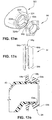
- a prior art respiratory mask system may include a cushion 24 comprising, for example, nasal pillows.
- the cushion 24 is supported on a rigid frame or shell 18 and a flexible component 22, for example a gusset, is provided between the cushion 24 and the frame 18.
- An air delivery hose or tube 16 is connected to the frame 18 for the delivery of the flow of pressurized breathable gas.
- a rigid headgear 20 is connected to the frame 18 to maintain the cushion 24 in sealing contact with the nose of the patient 1.
- Cushions which may be used in such a prior art respiratory mask system as shown in Fig. 1 include those disclosed, for example, in ResMed Ltd.'s Swift® LT.
- FIG. 2 schematically illustrates another respiratory mask system according to the prior art, the Fisher & Paykel Infinity® 481 mask.
- a cushion 24 comprising nasal prongs 23 is attached to a mask frame or shell 18.
- the mask frame includes headgear connectors 26 provided on sides of the mask frame 18.
- a vent including a plurality of vent holes 28 is also provided in the mask frame 18.
- the mask frame 18 is connected to an air delivery hose or tube 16 by a swivel elbow 17.
- the air delivery tube 16 is connected to a flow of pressurized breathable gas, such as generated by a blower or flow generator, by a coupling element 30.
- any relative movement between the mask frame 18 and the patient's face may result in a disruption of any seal that may have formed.
- One aspect relates to providing comfortable, stable, effective, unobtrusive patient interface systems for delivering a supply of air at positive pressure to the entrance of a patient's airways.
- Another aspect relates to a patient interface system that fits a wide range of patients, has improved manufacturability and improved ease-of-use.
- Another aspect relates to providing patient interface systems where forces applied to the patient interface structure, such as from tube drag forces or movement of the patient, does not disrupt the seal between the patient interface structure and the patient's airways.
- Yet another aspect relates to providing patient interface systems where the patient interface structure, which includes a seal, and a seal positioning and stabilizing structure are coupled to the patient and the air delivery tube is decoupled from the seal. Another aspect is that forces on an air delivery tube and elbow are decoupled from pillows and headgear.
- a further aspect relates to patient interface systems in which tension of the seal positioning and stabilizing structure may be set with a lesser regard to overcoming tube drag as the effects of tube drag are isolated from disrupting the seal via decoupling.
- the tension of the seal positioning and stabilizing structure may be reduced and patient comfort increased.
- Still another aspect relates to providing patient interface systems in which the patient interface structure is connected to a swivel elbow assembly without the use of a rigid frame or shell.
- Another aspect of the present technology is a conforming patient interface structure that reduces the number of, or does not include, rigid components.
- the patient interface does not include a rigid frame.
- Another aspect of the present technology is a patient interface structure that in use flexibly wraps around an underside of a patient's nose and accommodates different alar angles.
- Another aspect of the present technology is a patient interface structure that accommodates movement of an air delivery tube whilst maintaining an effective seal.
- Another aspect of the present technology is a stabilizing structure that directs a seal effecting force to a region close to the sealing surface, e.g. the base of the nose.
- a force close to the sealing surface reduces a bending arm.
- a front portion of a seal positioning and stabilizing structure is molded from a flexible polymer, for example silicone.
- the seal positioning and stabilizing structure does not include hard plastic stabilizers.
- a patient interface system for delivery of a supply of air at positive pressure to the entrance of a patient's airways for treatment of sleep disordered breathing comprises an air delivery tube connected to a flexible portion of a plenum; a vent structure having sufficient rigidity to support its own weight under gravity and/or not to block or fold under tube movement or tube drag; a patient interface structure, the patient interface structure comprising a seal forming structure arranged on a top portion of the plenum; and a seal positioning and stabilizing structure connected to a flexible portion of the plenum, wherein the seal-forming structure is substantially decoupled from a tube drag force.
- a nasal pillow for delivery of a supply of air at positive pressure to the entrance of a patient's airways for treatment of sleep disordered breathing comprises a stalk; a frusto-conical portion connected to the stalk at a base portion of the frusto-conical portion, the frusto-conical portion comprising a spring structure at base of the frusto-conical portion configured to engage the top lip of the patient and rotate the stalk away from the patient's top lip.
- a patient interface structure for delivery of a supply of air at positive pressure to the entrance of a patient's airways for treatment of sleep disordered breathing comprises a flexible base portion; a seal-forming structure connected to base portion; and lateral connectors connected to the flexible base portion substantially in a same plane as a base of the seal-forming structure, wherein the flexible base portion comprises a flexible side-walled plenum comprising an orifice adapted to receive the supply of air, the orifice having an axis substantially parallel to an axis of the seal-forming structure.
- a decoupling assembly for decoupling forces applied by a tube on a patient interface structure configured to deliver of a supply of air at positive pressure to the entrance of a patient's airways for treatment of sleep disordered breathing
- the patient interface structure comprising a flexible base portion connected to a seal-forming structure, the patient interface structure being held in engagement with the patient in use by a seal positioning and stabilizing structure connected to the flexible base portion
- the decoupling assembly comprising the flexible base portion, the seal-forming structure, and at least one of a portion of the seal positioning and stabilizing structure, a swivel elbow, a ball and socket, a swivel sealing ring, and the tube.
- a seal positioning and stabilizing structure for a patient interface structure for delivery of a supply of air at positive pressure to the entrance of a patient's airways for treatment of sleep disordered breathing comprises a flexible molded strap comprising a stiffened portion.
- a patient interface adapted to be connected to an air delivery tube comprises an under-the-nose gas delivery unit and a plurality of components operatively coupled to the gas delivery unit, said components including headgear, a plenum, frame, or base, and an elbow; and a decoupling system to decouple (or alternatively means for decoupling) at least a portion of a drag (or other dynamic force) from the air delivery tube which would otherwise be applied to the gas delivery unit.
- the gas delivery unit may be in the form of nasal prongs which are inserted into the nares to form a seal within the wearer's nasal passages, nozzles that seal against the lower, exterior surface of the nares, or nasal cannulae (which are partly inserted into the nasal passages but do not necessarily form a seal therewith).
- the nozzles may include stalks, heads or other structure to help contribute to decoupling of drag or other dynamic forces.
- the plurality of components may also include a sealing ring which may contribute to decoupling of tube drag force.
- the decoupling system may include two or more (or all) of said components (as well as the gas delivery unit itself, e.g, various portions of nozzles) working in concert with one another to decouple the force from the gas delivery unit.
- air will be taken to include breathable gases, for example air with supplemental oxygen. It is also acknowledged that blowers or flow generators described herein may be designed to pump fluids other than air.
- rigid will be taken to mean not readily deforming to finger pressure, and/or the tensions or loads typically encountered when setting up and maintaining a patient interface in sealing relationship with an entrance to a patient's airways.
- semi-rigid means being sufficiently rigid to not substantially distort under the effects of tube drag.
- Fig. 3a schematically illustrates an aspect of the present technology whereby headgear tension is directed close to the base of the nose and potentially disruptive effects of tube drag are isolated or decoupled from the seal. See also Fig. 4 .
- headgear structure attempts to stabilize a frame at a point spaced from the sealing surface (the base of the nose) and whereby the tube is directly coupled to the headgear via the rigid frame.
- a patient interface system may comprise a patient interface structure 32 configured to sealingly engage the airways of the patient 1.
- the patient interface structure 32 may comprise a seal, for example, nasal pillows or nasal prongs, to sealingly engage the patient's airways.
- nasal pillow refers to a nozzle-like structure that is configured to be inserted at least partly into the nasal passageway of the patient and form a seal against an outer surface of the patient's nare.
- Nasal pillows in accordance with the present technology include: a frusto-cone, at least a portion of which forms a seal on an underside of the patient's nose; a stalk, a flexible region on the underside of the cone and connecting the cone to the stalk.
- the structure to which the nasal pillow of the present technology is connected includes a flexible region adjacent the base of the stalk.
- the flexible regions can act in concert to facilitate a universal joint structure that is accommodating of relative movement- both displacement and angular- of the frusto-cone and the structure to which the nasal pillow is connected.
- the frusto-cone may be axially displaced towards the structure to which the stalk is connected.
- nasal prong refers to a nozzle-like structure that is configured to be inserted into the patient's nasal passageway and form a seal with the interior of the patient's nasal passageway.
- patient interface structure 32 may comprise a nasal patient interface structure or a full face patient interface structure, i.e. a structure configured to cover part of, or all of, the patient's nose and/or mouth and seal against the patient's face.
- the patient interface structure may be formed of, for example, silicone, foam, or gel.
- the patient interface structure 32 may be connected to an air delivery hose or tube 16 by a decoupling arrangement 34.
- the decoupling arrangement 34 may include, for example, a flexible portion of the patient interface structure 32, a swivel elbow including, e.g., a ball and socket connection, and/or a swivel seal ring.
- the air delivery hose may be a retractable hose, as disclosed, for example, in U.S. Application 12/211,896, filed September 17, 2008 , the entire contents of which are incorporated herein by reference.
- the patient interface system may also comprise a seal positioning and stabilizing structure 36 that is configured to position and stabilize the patient interface structure 32 in sealing engagement with the patient's airways.
- the seal positioning and stabilizing structure 36 may be flexible. As shown in Fig. 3a , the seal positioning and stabilizing structure is connected to the patient interface structure 32.
- the seal positioning and stabilizing structure 36 may include a side straps, or members, 38 configured to extend along each side of the patient's face, only one being shown in Fig. 3a , a top strap 40 configured to extend across the top of the patient's head, and a rear strap 42 configured to extend around the back of the patient's head.
- each side strap 38 of the seal positioning and stabilizing structure 36 may be attached to the patient interface structure 32.
- a connector may be provided on each side of the patient interface structure 32, one on each side of the nose of the patient 1.
- multiple connectors may be provided to the patient interface structure and in any arrangement, for example two connectors on each side of the nose of the patient.
- the pair of connectors form a connection between the patient interface structure 36 and the seal positioning and stabilizing structure 36 as described in more detail herein.
- the connection is close to the entrance to the nares of the patient 1.
- the straps 38, 40, 42 of the seal positioning and stabilizing structure 36 hold the seal in position against the face of the patient more directly than in prior art arrangements, such as the prior art arrangement shown in Fig. 1 .
- the connection of the seal positioning and stabilizing structure strap to the frame is displaced from the entrance to the patient's nares and the patient interface structure is held against the face of the patient in an indirect manner.
- the decoupling arrangement 34 is provided between the connection of the straps 38 of the seal positioning and stabilizing structure 36 and the connection with the air delivery tube 16 so that tube drag does not directly impact the seal formed between the patient interface structure 32 and the patient's airways.
- the tension of the headgear is often set at a level both to form a seal and to overcome tube drag that may occur.
- the tube drag is to some extent decoupled from the seal formed between the patient interface structure 32 and the patient's airways and the tension provided by the seal positioning and stabilizing structure need only be set at a level necessary for sealing.
- the tension may be set with a lesser regard for overcoming tube drag. The decreased tension provides increased patient comfort.
- the flexible seal positioning and stabilizing structure 36 may be configured so that the force vectors provided by the straps 38, 40, 42 of the seal positioning and stabilizing structure 36 maintain the patient interface structure 32 in sealing engagement with the nares of the patient 1. It should be appreciated, however, that other seal positioning and stabilizing structures may be utilized, as described in more detail herein.
- straps may be routed around and engaged with the ears of the patient.
- the straps may be eliminated and a nasal clip may be used to hold the seal of the patient interface structure 32 in position.
- the seal positioning and stabilizing structure 36 may be formed of a foam and fabric laminated material, such as BREATHOPRENE®.
- the seal positioning and stabilizing structure 36 may be made from silicone or other polymers.
- One of the benefits of using silicone or BREATHOPRENE® is there is no difference in temperature of patient's skin when using either silicone or BREATHOPRENE® headgear.
- silicone can discolor over time (typically oxidizes to yellow). Therefore, it may be desirable to add a tint, such as light blue, to the silicone to reduce the visual impact of discoloration.
- Sharp corners of the headgear may also be rounded to reduce incidences of irritation to the patient's skin.
- the silicone could be polished or matte on both sides or matte on one side and polished on the other - preferably matte on both sides, or matte on the skin contacting side and polished on the outer side. Matte surface finish gives the perception of comfort.
- the decoupling arrangement 34 acts as a flexible connection and links the patient interface structure 32 to the air delivery tube 16. According to the sample embodiment shown in Fig. 3a , only the seal of the patient interface structure 32 is held in a set location. There is no shell or frame that needs to be held in a set location. The decoupling arrangement 34 is free to move with the air delivery tube 16, thereby reducing tube drag and increasing the stability of the seal formed between the patient interface structure 32 and the airways of the patient 1.
- the seal positioning and stabilizing structure 36 also permits rotation of the plane of the patient interface structure 32 with respect to the seal positioning and stabilizing structure 36 to accommodate different naso-labial angles and different positions of the mask in use.
- the connectors provided on the patient interface structure 32 may include a plurality of connection points to allow the relative position of the patient interface structure 32 with respect to the seal positioning and stabilizing structure 36 to be changed or adjusted.
- the axis about which rotation may be provided may be defined as being parallel to a line drawn through both eyes of the patient, and being located below the nose of the patient.
- a desirable vector 404 will produce force normal to the nares.
- the entire vector 404 pulls the seal, e.g. the pillows, against the nares.
- the vectors of the seal positioning and stabilizing structure 36 of the sample embodiments are configured to force the seal, e.g. the pillows, up against the patient's nose.
- the vectors may be modified by the direction of the straps 38, 40, 42.
- the straps 38 may extend higher on the face (i.e. closer to the eyes than the ears of the patient's cheek) to increase force in the vertical axis thereby increasing the force up and against the user's nose.
- the shape of the straps 38,40,42 may also be configured to provide a desirable vector: According to sample embodiments, an arrangement without a frame requires orientation of the pillows using the seal positioning and stabilizing structure alone.
- the width of the straps may be varied to force the seal to tilt in the direction indicated by the vector 404.
- the width of the straps may be gradually increased from the cheek region to the nasal region to stabilize the patient interface structure 32.
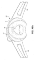
- a patient interface system includes a patient interface structure 32 including a flexible base 6. A seal is supported by the flexible base 6. The patient interface structure 32 is configured to be held in sealing engagement with the entrance to the patient's airways. The patient interface structure 32 is held in sealing engagement with the patient's face by a seal positioning and stabilizing structure 36 that includes a main strap loop 74 and a rear strap 42. The main strap loop 74 includes a right main strap 74r and a left main strap 741 that are configured to be connected at respective first ends to the patient interface structure 32.
- the right and left main straps 74r, 741 are configured to be connected to each other at respective second ends, for example by a connector 71, for example a buckle.
- a rear strap 42 of the seal positioning and stabilizing structure 36 extends around the back of the patient's head at a position above the patient's ears and is connected at respective ends to the right and left main straps 74r, 741 at positions between the first and second ends of the straps 74r, 741.
- a patient interface system includes a patient interface structure 320 including a flexible base. A seal is supported by the flexible base.
- the patient interface structure 320 is configured to be held in sealing engagement with the entrance to the patient's airways.
- the patient interface structure 320 is held in sealing engagement with the patient's face by a seal positioning and stabilizing structure that includes a main strap loop 74 and a rear strap 85 having adjustable ends 85e.
- the main strap loop 74 includes a right main strap 74r and a left main strap 741 that are configured to be connected at respective first ends to the patient interface structure 320.
- the right and left main straps 74r, 741 may be connected to each other at respective second ends, for example by a connector, for example a buckle.
- the rear strap 85 of the seal positioning and stabilizing structure extends around the back of the patient's head at a position above the patient's ears and is connected at respective ends to the right and left main straps 74r, 741 at positions between the first and second ends of the straps 74r, 741.
- the right and left main straps 74r, 741 may be formed, for example, from silicone.
- the silicone may be, for example, translucent or transparent.
- the patient interface system is therefore less obtrusive and presents a visually more appealing appearance (e.g. to a patient's bed partner).
- the "take off angle" of the straps 74r, 741 from a connection point provides a more direct angle to a base of the patient's temple and are generally higher up on the patient's face.
- the patient interface structure also conforms, or wraps around, the region of the patient's mouth and provides less interference with the area around the mouth.
- the seal positioning and stabilizing structure also covers less of an extent of the patient's face.
- a patient interface structure 32 includes a seal 2 configured to sealingly engage the patient's airways.
- the seal 2 may comprise a nozzle assembly 3 that may comprise a pair of nasal pillows 4 connected to a base portion 6.
- the pillows 4 each include a conical portion 8 at least part of which is adapted to form a seal with a nare of the patient 1.
- a portion of each pillow 4 is configured to be inserted into the patient's nasal passageway, but not to form a seal inside the nasal passageway.
- the conical portion 8 of the pillow 4 includes a sealing surface, or zone, 8a that is configured to engage the nare of the patient and form a seal.
- Each nasal pillow 4 also includes a stalk, or neck portion, 10 which connects the nasal pillow 4 to a flexible base 6.
- the stalk, or neck portion, 10 may have a length of between about 3 mm to about 6 mm.
- the flexible base 6 is able to wrap around the underside of the nose in use when under tension, and can accommodate different facial geometries.
- the flexible base 6 includes a pair of connectors 12 configured for connection to a seal positioning and stabilizing structure.
- the seal positioning and stabilizing structure connectors 12 are arranged at a top portion 6t of the flexible base 6, generally in the same plane as the base of the stalks of the nasal pillows 4.
- top portion refers to the portion of the flexible base that is adjacent to the seal of the patient interface structure.
- an axis through the stalks of the pillows is generally parallel to a normal to the aperture 324 wherethough a supply of air is delivered.
- This arrangement facilitates a generally narrower patient interface structure than for example the ResMed SWIFT® I (see for example Fig. 76A of WO 2004/073778 A1 ), or the Innomed NASAL AIRETM I where air is fed from the side leading to a wider overall mask structure, and hence a patient interface structure in accordance with the present technology is more amenable to side-sleeping by a patient.
- Other patient interface structures such as in the Fisher & Paykel OPUSTM and OPUSTM 360, include air delivery at an obtuse angle with respect to the angle of the axis of the nasal pillow when viewed from a corresponding orientation to Figs. 17g and 17h . This approach may lead to a greater bulk of structure.
- a lower portion 61 of the flexible base 6 forms part of a decoupling arrangement.
- the lower portion 61 of the flexible base 6 may comprise a gusset, such as the gusset disclosed in WO 01/97893 A1 , which is incorporated herein by reference.
- the term "lower portion” refers to the portion of the flexible base that is configured to be connected to an air delivery tube or hose, or to a frame or shell.
- the lower portion 61 may define a plenum with flexible side walls.
- the plenum is flexible, but not so limp or floppy that it cannot support its own weight. In other words, the plenum is capable of holding its shape before pressurization by the flow of breathable gas. In this sense, the plenum may be described as semi-rigid.
- the plenum may have flexible bellows-like structure on left- and right-hand sides, and narrowed portions adjacent the top lip and underside of nose to avoid contact therewith in use. See for example Fig. 17a where the end of line 329 is located in a flexible bellows-like region 339 and the end of arrow 320 is adjacent a narrowed region 321, as also shown in Fig. 18r . See also Fig. 17d where T4 indicates a thickness suitable to provide the flexibility illustrated in Figs. 42a - 42c and Figs. 43a - 43c .
- the flexibility of the plenum is facilitated by manufacture in a material such as silicone with a Shore A durometer in the range of about 20 to about 60, more preferably about 30 to about 50, most preferably about 40.
- a harder silicone may use thinner walls, a softer silicone may use thicker walls.
- a rounded bellows-like structure also facilitates flexibility independent of the material it is constructed from.
- Another plenum may be molded from polyurethane foam.
- Prior patient interfaces such as the Fisher & Paykel INFINITYTM 481, OPUSTM, OPUSTM 360, and the Respironics OPTILIFETM include a range of rigid materials such as polycarbonate.
- Other masks such as the AIRSEPTM Ultimate mask include rigid headgear connectors.
- the patient interface structure 32 may be formed in one piece, for example by molding a material such as silicone.
- the range of movement provided by the flexibility of the pillows 4 with respect to the top portion 6t of the flexible base 6 may be relatively small compared with the range of movement provided by the lower part 61 of the flexible base 6 acting as part of the decoupling arrangement.
- a strap of the seal positioning and stabilizing structure is attached to each seal positioning and stabilizing structure connector 12, one on each side of the nose of the patient, for example as shown in Fig. 3 , establishing a connection.
- the connection is close to the plane of the entrance to the nares of the patient.
- the straps of the seal positioning and stabilizing structure 36 more directly hold the nasal pillows 4 in position than in prior art arrangements, such as shown in Fig. 1 , where the connection is displaced from the plane of the entrance to the nares of the patient.
- a patient interface structure 32 may comprise a seal 2 comprising a nozzle assembly 3 having a pair of nasal pillows 4.
- the flexible base 6 may include integrally formed connectors 50.
- the patient interface structure 32 may be coupled to a decoupling arrangement, e.g. a swivel ring, to decouple tube drag forces as will be described in more detail.
- Each nasal pillow 4 may include a conical portion 8 and a neck portion 10. Each conical portion 8 may comprise a sealing zone 8a configured to form a seal against the patient's nare.
- the nasal pillows 4 may be formed with the patient interface structure 32 or may be removably attached to the patient interface structure 32, for example as described in WO 2005/063328 , the entire contents of which are incorporated by reference.
- the patient interface structure 32 may further comprise an aperture 46 for introduction of a flow of breathable gas into the patient interface structure 32.
- the aperture 46 may be formed in a lower portion 61 of flexible base 6 and be surrounded by a flange 48 that is configured for engagement with an air delivery tube, or a swivel elbow assembly, or a ball and socket joint. It should also be appreciated that the flange 48 of the patient interface structure 32 may be configured for connection to a frame or shell.
- the patient interface structure 32 may be formed of a flexible material, such as silicone.
- the patient interface structure 32 may be formed of one piece, including the nasal pillows 4, the flange 48, and a pair of connectors 50 provided at each end of the patient interface structure 32.
- each connector 50 may comprise a first slot 52 and a second slot 54 for receipt of an end of a strap of the seal positioning and stabilizing structure.
- the first slot 52 and a second slot 54 are separated by a crosspiece 56 which may engage the end of the strap to retain the end of the strap in contact with the connector 50.
- the patient interface structure, including the connectors 50 is flexible and forces applied by the seal positioning and stabilizing structure, for example by side straps, stretch the connector 50 to increase the force that the crosspiece 56 exerts on the seal positioning and stabilizing structure strap.
- the patient interface structure 32 may be integrally formed, for example by molding.
- the patient interface structure 32 may be formed so as to have varying densities and/or hardnesses.
- the nasal pillows 4 and/or the flexible base 6 may be formed of a first density and/or hardness and the connectors 50 may be formed of a second density and/or hardness.
- the second density and/or hardness may be higher than the first density and/or hardness. This permits the patient interface structure 32 to be formed so as to have a softer feeling in those areas that engage the patient's face (e.g. the nozzle assembly of the seal) and a harder, or more rigid, feeling in the area connected to the seal positioning and stabilizing structure.
- the hardness e.g.
- durometer, of the patient interface structure may be different from the hardness of the seal positioning and stabilizing structure discussed below.
- the durometer of the connectors and/or flexible base of the patient interface structure may be different from the straps and/or the connectors of the straps of the seal positioning and stabilizing structure.
- a patient interface system includes a patient interface structure 32a comprising a seal 2a including a nozzle assembly 3a.
- the nozzle assembly 3a comprises a pair of nasal prongs 4a.
- Each nasal prong 4a includes a stalk, or neck portion, 10a that connects the nasal prong 4a to a flexible base 6a of the patient interface structure 32a.
- Flaps 4b are provided between the nasal prongs 4a and the stalks 10a.
- the nasal prongs 4a form a seal with the nasal passageways of the patient when the nozzle assembly 2a is held by a seal positioning and stabilizing structure in engagement with the face of the patient.
- a pair of seal positioning and stabilizing structure connectors 12a are provided on a flexible base 6a of the patient interface structure 32a.
- Connectors 12a are provided on the flexible base 6a for the connection of straps of a seal positioning and stabilizing structure with the patient interface structure 32a.
- the connectors 12a may include a plurality of connection points 13a, 13b to allow the relative position of the patient interface structure 32a with respect to the seal positioning and stabilizing structure 36 to be changed or adjusted.
- a patient interface system may include the patient interface structure of Fig. 5a and a mask shell or frame as shown in Fig. 2 that is modified to not include the connectors on the frame and includes a vent having a plurality of vent holes.
- the mask frame may be connected to an air delivery tube by a swivel elbow.
- the ends of the swivel elbow may include ball and socket type connections to the frame and the air delivery tube so that the swivel elbow acts as a decoupling element or joint.
- the delivery tube may receive a flow of pressurized breathable gas by being connected through a coupling element to a flow generator or blower.
- the mask frame of Fig. 2 may be formed of a flexible material, instead of a rigid material as in the prior art shown in Fig. 2 , and the connectors 12 may be provided on the flexible frame.
- the elbow may be flexible. In such a form, it may be desirable to locate the vent holes elsewhere on the mask system. Alternatively, a solid vent insert may be placed in the flexible elbow. In another form, reinforcement may be provided to the flexible elbow to maintain its structural integrity and prevent the tube from occluding.
- the seal positioning and stabilizing structure connectors 12a are provided at a point just below the flaps 4b of the nasal prongs 4a.
- the seal positioning and stabilizing structure connectors 12a are connected to the neck, or base, portions 10a of the nasal prongs 4a.
- the plane of connection formed by the seal positioning and stabilizing structure connectors 12a is closer to the plane of the entrance to the nares of the patient than the embodiment shown in Fig. 5a .
- the patient interface structure of Fig. 6 may also be used with a mask frame such as shown in Fig. 2 that is modified to not include connectors on the frame. It should also be appreciated that the patient interface structure of Fig. 6 may be used with a mask frame such as shown in Fig. 2 that is modified to be formed of flexible material.
- a patient interface structure according 32 may comprise a seal 2 comprising a nozzle assembly 3 having nasal pillows 4.
- the patient interface structure 32 may include an optional linking portion or element 47 configured to link tension forces applied by the seal positioning and stabilizing structure from one side of the patient interface structure 32 to the other side in order to isolate forces applied by the seal positioning and stabilizing structure at the top portion 6t of the flexible base 6, and thereby isolate tube drag forces at the lower portion 61 of the flexible base 6 of the patient interface structure 32.
- the line of force defined by the linking element is preferably close to the base of the nose when used in an under-the-nose type mask such as nasal pillows or nasal prongs.
- the linking element 47 may take the form of a stiffened and/or reinforced top portion 6t when compared to the lower portion 61 of the flexible base 6.
- the lower portion 61 may include, or take the form of, a gusset, for example as disclosed in WO 01/97893 .
- the gusset may also be configured similarly to an accordion, having multiple ridges to increase its springiness and flexibility, for example as disclosed in WO 2006/074515 , the entire contents of which are incorporated herein by reference.
- the gusset may also be reinforced to control where and how it collapses, i.e. so that it can move laterally and axially but cannot compress vertically.
- Reinforcement may include supporting ribs, thickened sections or regions, or a rigid or semi-rigid skeleton with a flexible material surrounding it.
- Stiffening and/or reinforcing may be achieved by a thickening of the material used in the patient interface structure 32, for example increasing the thickness of the silicone by up to about 10 mm at the top portion 6t when compared to the lower portion 61 of the flexible base 6.
- Such stiffening and/or reinforcing may also be achieved through the use of a higher hardness material positioned at the top portion 6t, for example silicone of a durometer between about 50 - 80 on the Shore A hardness scale.
- metal inserts for example a wire(s) or mesh(es), may be used in the linking element 47.
- Stiffening and/or reinforcing may also be achieved by a gel insert. The gel insert may also increase patient comfort, for example at the septum.
- stiffening and/or reinforcing may also be achieved by a foam insert.
- the foam insert may increase patient comfort, for example at the septum, and act as a secondary seal should a leak form at the primary seal.
- the linking element 47 may also be formed of a co-molded, generally inextensible material, for example nylon, TPE, metal, or alloy.
- the linking element 47 may also be in the form of a beaded, thickened portion, as described in more detail below.
- stiffening and/or reinforcing the top portion 6t for example to form the linking element 47, will result in the lower portion 61 being more extensible so that forces applied by the seal positioning and stabilizing structure are more isolated from the lower portion 61. This allows the lower portion 61 of the flexible base 6, for example the gusset, to flex more easily while ensuring that the nasal pillows 4 are held in sealing contact with the nares of the patient.
- the linking element 47 may be configured in such a way that it is stiff along its length, e.g. from connector 50 to connector 50, but elastic through its height, i.e. in the general direction of the nasal pillows 4. This enables the neck portions 10 of the nasal pillows 4 to flex more readily while maintaining the primary function of the linking element 47, i.e. isolating the forces applied by the seal positioning and stabilizing structure.
- the linking element 47 may be formed from a material that can be molded to the patient's face, for example the plastic material used to form mouth guards. This would provide the benefit of isolating forces and increasing the comfort of the patient interface system due to its unique fit.
- the linking element 47 may extend across the entire top portion 6t of the flexible base 6, from connector 50 to connector 50, and including the entire width. See, for example, W1 in Fig. 17a .
- the linking element 47 may extend over a section, or sections, of the top portion 6t of the flexible base 6, for example only the section of the top portion 6t between the nasal pillows 4.
- the linking element 47 may cover a fraction of the width of the top portion 6t, for example half the width.
- the tension linking element 47 may cover a section, or sections, of the top portion 6t as long as it is sufficient to isolate the forces as described above.
- the linking element may be formed as a series of ridges 47a.
- the number of ridges 47a may be determined in order to sufficiently isolate forces as described above.
- the ridges 47a may be provided to the top portion 6t only between the nasal pillows 4.
- the ridges 47a may be thicker than the top portion 6t.
- the ridges 47a may be generally circular or rectangular or any other shape.
- the ridges 47a may extend upwards and/or downwards from the top portion 6t.
- the ridges 47a may also be formed from a material of higher hardness than that used to form top portion 6t, for example higher durometer silicone, or metal.
- the ridges 47a may be formed in one piece with the patient interface structure 32, or may be retrofitted to the patient interface structure 32.
- the linking element e.g. the ridges 47a
- the ridges 47a may also be independent of one another, or the ridges 47a may be joined together. In the case of the linking elements comprising inserts, the inserts may be separately provided, or connected together.
- the ridges 47a may also be formed of individual shapes, sizes, thicknesses, materials, and/or hardnesses.
- the ridges 47a may be provided to the top portion 6t along the entire length of the flexible base 6, i.e. from connector 50 to connector 50.
- the linking element 47 may be formed in the top portion 6t of the flexible base 6 of the patient interface structure 32.
- the patient interface structure 32 may be molded around the linking element 47 so that the linking element 47 is embedded within the top portion 6t of the flexible base portion 6 of the patient interface structure 32.
- the linking element 47 may be formed, for example, of metal or plastic material.
- the linking element may also be in the form of, for example, a wire or a mesh.
- the linking element 47 may be provided along the top portion 6t of the flexible base 6.
- the linking element 47 may include slots or openings 47o that correspond with the first and second slots 52, 54 of the connector 50 to accept the straps of the seal positioning and stabilizing structure that connect to the patient interface structure 32.
- the linking element 47 may have an outline that matches the top portion 6t of the flexible base 6 of the patient interface structure 32 and comprise openings 47p that are configured to receive the stalks or neck portions 10 of the pillows 4.
- the linking element 47 may also include slits 47s that allow the portions of the linking element 47 around the openings 47p to be displaced with respect to one another to insert the linking element 47 over the pillows 4 and onto the top portion 6t of the flexible base 6.
- the element 47 may be formed of, for example, metal or plastic.
- the linking element 47 may be a thin metal sheet that is stamped into the configuration shown in Fig. 8h . It should also be appreciated that the connectors 50 of the patient interface structure 32 may be eliminated and the straps of the seal positioning and stabilizing structure connected directly to the linking element 47 without any direct connection to the patient interface structure 32.
- a linking element 47 may extend around the neck portions 10 of the pillows 4. As shown in Fig. 8j , the linking element 47 may have a figure eight configuration and include openings 47p that are configured to receive the neck portions 10 of the pillows 4.
- the linking element 47 may be formed from, for example, metal or plastic.
- the linking element 47 may be formed from a wire.
- the linking element 47 may comprise a bridging portion between the stalks or neck portions 10 of the nasal pillows 4.
- the linking element 47 may be integrally formed, e.g. by molding, with the patient interface structure 32.
- the linking element 47 may also be formed of a different material than the material used to form the patient interface structure 32.
- the linking element 47 may be formed of a higher durometer material than the patient interface structure material.
- the linking element 47 may be formed to be more rigid than the top portion 6t of the flexible base 6 of the patient interface structure 32.
- each nasal pillow 4 may comprise a pillow orifice 5 for delivering breathable gas to the nares of the patient.
- Each pillow 4 is inserted into a nare of the patient and is sealed at a sealing surface 11.
- the pillow orifice 5 is offset from a neck orifice 9 of the stalk or neck portion 10 along a major axis 13 of the elliptically shaped nasal pillow 4 by shifting the pillow orifice 5 along the major axis 13.
- the portion 11a of the sealing surface 11 that is in contact with the upper lip of the patient is thus reduced, which may increase patient comfort.
- the pillow orifice 5 is shown shifted from the neck orifice 9 along the major axis 13, it should be appreciated that the pillow orifice 5 may be shifted along the major axis 13 and/or the minor axis 15.
- a patient interface structure 320 includes connectors 322 on each side and connected to a flexible base 329 of the patient interface structure 320 by extensions 323. It should be appreciated that the connectors 322 may be connected by the extensions 323 to respective neck portions 332 of a pair of nozzles 328 in a manner similar to that discussed above with respect to Fig. 6 .
- the connectors 322 may be linear with the upper surface of the flexible base 329 (as shown in Figs. 17b and 17d ). Alternatively, the connectors 322 may be tilted or angled to alter the position of the patient interface structure 320 when connected to the seal positioning and stabilizing structure.
- the patient interface structure 320 comprises a seal 333 comprising a nozzle assembly comprising the pair of nozzles taking the form of nasal pillows 328.
- the pillows 328 each comprise a neck portion 332 that is connected to the flexible base 329 that defines a nasal breathing cavity 336.
- each nasal pillow 328 comprises an inner conical portion 334 and an outer conical portion 330.
- Such pillows are disclosed, for example, U.S. Patent Application Publications 2007/0144525 A1 and 2006/0283461 A1 , the entire contents of each being incorporated herein by reference. It should also be appreciated that the nasal pillows may be as described in, for example, U.S.
- the outer conical portion 330 comprises a sealing surface, or zone, 330a that is configured to seal against the patient's nare. As shown in Fig. 17d , the inner conical portion 334 and the outer conical portion 330 may have different thicknesses.
- the flexible base 329 includes an aperture 324 for the introduction of the flow of breathable gas.
- the flexible base 329 further comprises a flange 326 that extends radially inwardly and defines the aperture 324.
- the flange 326 may comprise a chamfer 327 for insertion of a swivel sealing ring as discussed in more detail below.
- the flexible base 329 of the patient interface structure 320 may thus be connected to a frame, a swivel elbow, or a tube or conduit as also described in more detail below.
- the flexible base 329 may include a linking element(s), similar to the one disclosed and discussed with respect to Figs. 8a - 8g ,for example in between the neck portions 332 of the nasal pillows 328.
- the aperture 324 may have a diameter D1 of about 17 mm - 20 mm, for example about 18.5 mm.
- the patient interface structure 320 may have a width W1 of about 25 mm - 35 mm, for example about 30.5 mm.
- the patient interface structure 320 may have a length L1 of about 80 mm - 90 mm, for example about 84.5 mm.
- the seal positioning and stabilizing structure connector 322 may have a length of about 12 mm - 18 mm, for example about 15.5 mm.
- the flexible base 329 may have a length L3 of about 45 mm - 50 mm, for example about 47.5 mm.
- the patient interface structure 320 may be a height H1 of about 30 mm - 37 mm, for example about 33 mm.
- the base portion 329 may have a height H2 of about 15 mm - 23 mm, for example about 19 mm.
- the extensions 323 may have a thickness T1 of about 1.5 mm - 2.0 mm, for example about 1.8 mm.
- the flexible base 329 may have a thickness T2 between the nasal pillows 328 of about 1.5 mm - 2.5 mm, for example about 2.0 mm. It should be appreciated that the thickness T2 may be greater, for example in the case where a linking element is formed in one piece with the patient interface structure 320 between the nasal pillows 328.
- the flange 326 may have a thickness T3 of about 1.5 mm - 2.5 mm, for example about 2.0 mm.
- the flexible base 329 may have a thickness T4 of about 0.6 mm -1.0 mm, for example about 0.8 mm.
- the stalks 32 may have a length of about, for example, 3 mm to about 6 mm.
- the pillows 328 may comprise the outer conical portion 330 and the inner conical portion 334.
- a portion 360a of a sealing zone 360 of the outer conical portion 330 that is in contact with the upper lip of the patient is displaced an equal distance 362 from the stalk or neck portion 332 of the pillow 328 as a portion 360b of the sealing zone 360 that is in sealing engagement with the nares of the patient.
- the sealing zone 360 and the pillow orifice 354 are non-concentric with the stalk 332 of the pillow 328.
- the portion 360a of the sealing zone 360 that engages the upper lip of the patient is displaced a distance 364 that is not equal to the distance 366 that the portion 360b is displaced from the stalk 332.
- the pillow orifice 354 and the sealing zone 360 are concentric with the stalk 332.
- the portion 360a is displaced an unequal amount from the stalk 332 than the sealing zone portion 360b.
- the sealing zone 360 and the pillow orifice 354 are concentric with the stalk 332.
- a supporting rib 368 may be provided under the portion 360b of the sealing zone 360 to maintain the pillow sealing zone in an upright position so that it may seal at the nares.
- the inner conical portion 334 and the outer conical portion 330 are tilted at an angle 370 with respect to the stalk 332 of the pillow 328.
- the angle tilts the pillow towards the face of the patient and may be, for example, -30° to 45°, as another example 15°.
- the portion 360a configured to engage the upper lip of the patient has a larger radius than the sealing zone portion 360b to provide for greater patient comfort.
- the pillow orifice 354 and the sealing zone 360 are eccentric with respect to the stalk 332.
- the orifice of the inner conical surfacel 100, the outer 1000 walls and stalk 1200 of the nasal pillow 1150 are concentric with respect to a center line CL.
- the radius of the portion 1600 on the opposite side to portion 1500 is smaller than the radius of the portion 1500 that is adjacent to the upper lip of the patient.
- the larger radius of portion 1500 has a thickened region 1550 that assists in avoiding contact between the nasal pillow and the top lip, pushing the structure away therefrom. Avoiding contact with the top lip can improve comfort for some patients.
- An advantage of this is that the need to provide a separate manual pillows rotation mechanism may be reduced since the pillow may automatically move away from the top lip, adjusting to the naso-labial angle of the patient. This may in part be assisted by flexure of the patient interface structure connectors 84 of the seal positioning and stabilizing structure.
- the base of the pillow 1150 is angled with respect to the top of a linking element 1400.
- the angle ⁇ allows the linking element 1400 to tilt.
- the thickened region 1550 results in a relatively stiffer spring structure than the thinner portion 1600 that may rotate the patient interface structure away from the top lip. Since the base of the pillow 1150 is angled ⁇ with respect to the linking element 1400, the linking element 1400 aligns with the base of the pillow 1150 so that they are flush or in constant contact along the whole surface of the base of the pillows 1150. This means that the linking element 1400 and adjacent trampoline 1300 rotates upwards, i.e. rotates by ⁇ ° towards the top of the patient's nose. The linking element 1400 and the trampoline 1300 are thereby angled away from the bottom of the pillows or upper lip of the patient. This improves the comfort and stability of the patient interface system.
- the rotation of the trampoline 1300 and the linking element 1400 away from the patient's upper lip could similarly be achieved by skewing the shape of the trampoline 1300 and/or linking element 1400 (e.g. by altering the dimensions of the flexible base of the patient interface structure), change the trampoline properties so that it is stiffer in some regions compared to other regions to force the stalk to collapse in a certain way (e.g. stiffer towards the bottom of the pillows/upper lip side) or changing the properties of the stalk to cause it to collapse more in one direction than another (e.g. stiffer towards the bottom of the pillows/upper lip side).
- skewing the shape of the trampoline 1300 and/or linking element 1400 e.g. by altering the dimensions of the flexible base of the patient interface structure
- change the trampoline properties so that it is stiffer in some regions compared to other regions to force the stalk to collapse in a certain way (e.g. stiffer towards the bottom of the pillows/upper lip side) or changing the properties of the stalk to cause it to
- the nasal pillows 328 may comprise elliptical inner and outer conical portions 334, 330, respectively.
- the orifices 354, 355 of the inner and outer conical portions 334, 330, respectively may be offset along a major axis of the ellipses.
- the radius of the portion 360a of the sealing zone 360 configured to engage the upper lip of the patient is larger than the radius of the portion 360b configured to seal the nare of the patient.
- the pillows 328 may be provided with cut outs, or truncated portions, 350 for improved upper lip comfort of the patient.
- the pillow orifice 354, the sealing zone 360, and the stalk 332 are concentric.
- the upper lip contacting side of the pillow 328 includes a truncated portion 350 to prevent interference and discomfort.
- the pillow orifice 354 and the sealing zone 360 are concentric along the centerline 358.
- the stalk 332 is not concentric with the centerline 358 so that the stalk orifice 356 is offset from the pillow orifice 354.
- the stalk 332 may be offset in a direction away from the truncated portion 350.
- the stalk 332 may be offset in a direction towards the truncated portion 350.
- the stalk 332 may be provided at a position coincident with the portion 360b of the sealing zone 360 that is configured to engage the patient's upper lip.
- the outer conical portion 330 of the pillow 328 may be provided at an angle with respect to the stalk 332 and/or the stalk may be angled and/or have a variable cross section.
- the nasal pillows 328 may be conjoined.
- the portions 360a of the sealing zones configured to contact the patient's upper lip may have a shallow radius and the portions 360b configured to engage the nares may have a large radius at the outer edges of the sealing zones to increase the fit range of the pillows.
- the pillows 328 may have a generally rose bud shaped configuration, as shown in the drawings.
- the sealing zone of the pillow may have a large radii on either side, or both sides.
- the pillow may act as a nasal dilator.
- the pillows 328 may have a generally olive shaped configuration.
- a patient interface system includes a patient interface structure 32 that includes a flexible base 6.
- a seal 2 is provided on the flexible base 6.
- the seal 2 may be formed of foam.
- a swivel elbow 17 is connected to the flexible base 6 for delivery of a flow of breathable gas from a hose or tube or conduit (not shown) connected to the swivel elbow 17 into a nasal breathing cavity defined by the flexible base 6 and the seal 2.
- the patient interface structure 32 is held in sealing engagement with the patient's face by a seal positioning and stabilizing structure 36 that comprises side straps 38, a top strap 40 ( Fig. 45c ), and a rear strap (not shown).
- a seal positioning and stabilizing structure 36 that comprises side straps 38, a top strap 40 ( Fig. 45c ), and a rear strap (not shown).
- the side straps 38 are shown connected to the flexible base 6 in an integral fashion, it should be appreciated that the side straps 38 may be connected to the flexible base 6 in a manner that allows connecting and disconnecting the side straps 38 from the flexible base 6, for example as discussed in more detail herein. It should also be appreciated that one, or both, side straps 38 may be configured to be connectable and disconnectable from the flexible base 6.
- the seal 2 includes an aperture 19 that is configured to surround both nares of the patient.
- the flexible base 6 is conformable and in use wraps around the nose of the patient 1.
- the seal 2 may be configured to seal in part above the tip of the patient's nose.
- the seal positioning and stabilizing structure 36 may be formed, for example, from a flat silicone sheet.
- a headgear for a respiratory mask is formed from a foam and fabric laminate, such as BREATHOPRENE®.
- Such headgear is die cut and thus has squared edges. This can appear bulky on the face of the patient and can be uncomfortable due to its edges.
- seal positioning and stabilizing structure made from silicone may be molded to have rounded edges. Such rounded edges improve comfort. In one form, the rounded edges may have a radius of greater than about 0.5 mm. As shown in Fig.
- the straps 38,40,42 of the seal positioning and stabilizing structure 36 may have the rounded edges 420 formed on the patient contacting (i.e. skin contacting) side 418 of the straps 38, 40, 42.
- the parting line 416 of the tool that forms the straps 38, 40, 42 may be further from the patient contacting side 418 to avoid flash near the patient's face that can cause irritation.
- the straps 38, 40, 42 may include a larger radius 422 on the patient contacting side 418 by providing portions 424 on the opposite side that are rolled back from the parting line 416.
- the seal positioning and stabilizing structure 36 may include two side straps 38 (only one visible in Fig. 7a ), a top strap 40, and a rear strap 42. Respective ends 38a of the side straps 38 are connected to connectors 12 (only one visible in Fig. 7a ) provided on the flexible base 6 of the patient interface structure 32.
- the connectors 12 are located on sides of the flexible base 6 to which nasal pillows may be connected. The connection of the connectors 12 to the flexible base 6 enables the flexible base 6 to wrap around the base of the nose of the patient and be pulled back to retain the nasal pillows in a sealing relationship with the underside of the patient's nose.
- the respiratory mask system of Fig. 7a may be adjusted by adjusting the connection of the ends 38a of the side straps 38 with the connectors 12.
- the connectors 12 may each include a slot, or slots, configured to accept the end 38a of the side strap 38.
- the sealing force provided by the seal positioning and stabilizing structure 36 may be adjusted by adjusting the ends 38a of the side straps 38.
- the patient 1 may pull on the end(s) 38a of the side strap(s) 38.
- the sealing force may be decreased by shortening the end(s) 38a of the side strap(s) 38, e.g. by pulling the side strap(s) 38 back through the connector(s) 12.
- the patient interface structure 32 may be rotated with respect to the seal positioning and stabilizing structure 36 about an axis generally parallel to a line drawn through both eyes of the patient and below the patient's nose by the inherent flexibility of the straps. It should also be appreciated that inelastic straps may be used. It should be further appreciated that angular adjustment of the patient interface structure 32 with respect to the seal positioning and stabilizing structure 36 may be achieved by an adjustment buckle(s)/connector(s), such as those disclosed, for example, in U.S. Patent 6,907,882 , the entire contents of which are incorporated herein by reference.
- the seal positioning and stabilizing structure 36 may comprise a strap 41 configured to encircle the patient's head at a position above the patient's ears.
- a side seal positioning and stabilizing structure strap 38 (only one visible in Fig. 10 ) extends along each side of the face of the patient 1 and is connected to a respective side of the patient interface structure 32.
- the patient interface structure may be connected to a swivel elbow or joint 17 through a decoupling arrangement 34, although it should be appreciated that the patient interface structure may be connected to a rigid, or semi-rigid, frame or shell.
- the swivel elbow is connected to an air delivery tube 16 for the delivery of the flow of pressurized breathable gas.
- a stiffening, or reinforcing, element 66 may be connected to each side strap 38. As shown in Fig. 10 , in order to avoid impingement on the vision of the patient 1, the stiffening or reinforcing element 66 traverses the eye socket of the patient 1. The provision of the stiffening elements thus allows for the force vectors of the seal positioning and stabilizing structure to pass near the eyes of the patient without obscuring the patient's vision. Hence a tension force may be directed in a more ideal direction, orthogonal to the sealing surface, in this case the underside of the patient's nose.
- the stiffening element 66 may be constructed from a material sufficiently stiff along the longitudinal length to resist bending under the seal positioning and stabilizing structure tension forces, but able to conform in an out of plane direction to lie flat on the patient's face. Suitable materials for the stiffening elements 66 include, for example, nylon, polypropylene, and silicone.
- the stiffening elements 66 may be threaded through the side straps 38, or the stiffening elements 66 may be adhered or stitched in place on the side straps 38. Alternatively, the stiffening elements may be movable on the side straps 38 of the seal positioning and stabilizing structure 36, for example, by sliding along the side straps 38.
- the top strap 40 may be configured to extend at an angle to the rear strap 42. This configuration produces force vectors that increase the sealing force applied by the seal positioning and stabilizing structure 36 without increasing the tension. A component of the force provided by the top strap 40 is directed upward, which increases the sealing forces applied to the patient interface structure 32. In other words, the sealing force component of the top strap 40 is added to the sealing force component of the side straps 38 to provide improved sealing without increasing tension.
- a patient interface system comprises a seal positioning and stabilizing structure 36 connected to a patient interface structure 32 by lateral side arms 68 provided on each side of the face of the patient 1.
- Each lateral side arm 68 may comprise a first side arm connector 68a connected to the patient interface structure and a second side arm connector 68b, with respect to the orientation shown in Fig. 12a , below the first side arm connector 68a, connected to the patient interface structure 32.
- the lateral side arm 68 may be connected to the rear strap 42 of the seal positioning and stabilizing structure 36 through a slot 68c provided in the lateral side arm 68 that receives the rear strap 42. As shown in Figs.
- a side strap 38 of the seal positioning and stabilizing structure 36 may extend along a portion of the lateral side arm 68. It should be appreciated, however, that the side strap 38 maybe eliminated and the lateral side arm 68 may extend from the junction of the top strap 40 and the rear strap 42. Each lateral side arm 68 may be configured to lie on the face of the patient from a point in the general region of the temple to near the base of the patient's nose.
- the lateral side arms 68 may be formed of material similar to the stiffening elements described above with reference to Figs. 10 and 11 .
- the lateral side arms 68 may be formed from a soft flexible material, for example a laminate of compressed foam and fabric material, such as BREATHOPRENE®.
- the lateral side arms 68 may be constructed to be sufficiently stiff along the longitudinal length to avoid bending under the seal positioning and stabilizing structure tension forces, but able to conform in an out of plane direction to lie flat on the patient's face.
- the first and second side arm connectors 68a, 68b are connected to the patient interface structure 32 at two points and are sufficiently wide at the connections to improve control over the rotational stability of the seal, but permit rotation of the patient interface 32 to present the seal, e.g. nasal pillows, at a right angle to the sealing surface.
- the lateral side arms 68 may be connected to the side straps 38 through slots 68c.
- the side straps 38 may be connected to the strap 41 by a strap connector 70.
- the side strap 38 is connected at one end to the strap connector 70 and at the opposite end to the lateral side arm 68 through the slot 68c.
- the strap connector 70 may be moved along the strap 41 to allow the patient to adjust the position of the lateral side arms 68.
- the patient may thus adjust the position of the lateral side arm 68 to effect a good seal between the patient interface structure 32 and the nares of the patient, and the patient interface system may be adjustable to fit patients of a variety of sizes.
- the seal positioning and stabilizing structure 36 may be formed of a single piece, including the top strap 40, the rear strap 42, the side strap 38 and the lateral side arms 68.
- a buckle 71 may be provided on the top strap 40 to adjust the fit of the seal positioning and stabilizing structure 36 to the patient. It should be appreciated that the buckle may be provided additionally or alternatively to the rear strap 42.
- the single piece seal positioning and stabilizing structure 36 may be connected to the patient interface structure 32 by connectors such as hook and loop fasteners.
- the single piece seal positioning and stabilizing structure 36 may be a complete circular component that can wrap around the patient interface structure 32 at, for example, the base of the patient interface structure 32 between the patient interface structure 32 and the elbow 17, or at the top of the patient interface structure 32 between the flexible base of the patient interface structure 32 and the seal (e.g. nozzle arrangement).
- the entire patient interface system, including the patient interface structure 32 and the seal positioning and stabilizing structure 36 may be formed as a single component.
- the elbow 17 may also be formed with the patient interface structure 32 and the seal positioning and stabilizing structure 36.
- the lateral side portions 68 may divide into first and second side arm connectors 68a, 68b to form a triangular cut out proximal to the patient interface structure 32, as shown in the figures.
- the lengths of the first and second side arm connectors 68a, 68b affect the angle at which the patient interface structure 32 is positioned. For example, if the first side arm connector 68a is longer than the second side arm connector 68b, the patient interface structure 32 is likely to rotate away from the patient's nares.
- the length of the first side arm connector 68a may be adjustable, thereby rotating the patient interface structure 32, by an adjustment mechanism, such as a buckle.
- adjustment may be provided to the second side arm connector 68b to alter its length and thus rotate the patient interface structure, for example by an adjustment mechanism such as a buckle. Adjustment may also be provided to both the first side arm connector 68a and the second side arm connector 68b to allow greater adjustment of the patient interface structure 32.
- the side strap 38, the top strap 40, and the rear strap 42 of the seal positioning and stabilizing structure 36 are connected by a connector 72.
- the side strap 38 may be connected to the patient interface structure 32 by a seal positioning and stabilizing structure connector 12 which is provided on the patient interface structure 32.
- the patient interface structure 32 may be connected directly to an air delivery tube 16 by a swivel elbow 17.
- the connector 72 allows the position of each of the straps 38, 40, 42 to be adjusted to allow the patient to effect a seal between the patient interface structure 32 and the airways of the patient and allows the seal positioning and stabilizing structure 36 to be sized and fitted to a variety of patients.
- Figs. 24m-24q show a patient interface assembly including an eighth embodiment of a seal positioning and stabilizing structure.
- the seal positioning and stabilizing structure includes a main strap loop 74, and rear strap 85.
- main strap loop 74 includes a strap connector 82 arranged to connect rear strap 85 at an angle A with respect to the crown engaging top portion main loop 74 of about 90° to about 140°, preferably about 95° to about 110°, most preferably about 100°.
- the main strap loop 74 has a curved middle portion in between two generally straight portions.
- the first straight portion lies over the crown of the patient's head in use.
- the second straight portion has one end connected with a lateral portion of the patient interface structure, and is generally parallel therewith.
- the curved middle portion corresponds to the stiffened region 78 discussed below.
- the angle B between the two straight portions is preferably in the range of about 150° to about 90°, for example about 130° to about 90°, more preferably about 120° to about 100°, most preferably about 111 °.
- the stiffened, curved portions allows headgear tension forces to be applied to the underside of the patient's nose at a more effective angle, preferably orthogonal to the underside of the nose, without the headgear obscuring the patient's vision, or contacting sensitive eye regions.
- the preferred arrangement there is no sharp change in direction, compared to for example, the ResMed Swift® LT.
- this headgear (i.e. seal positioning and stabilizing structure) arrangement avoids impinging on patient's ears in a wider range of head sizes.
- an angle Y between a line generally perpendicular to the strap connector 82 and a line extending through the first end of the strap loop 74 may be in a range of from 90° to about 140°, preferably about 95° to about 125°, most preferably about 100°.
- the seal positioning and stabilizing structure may include a main strap loop 74 including right and left main straps 74r, 741, shown in Fig. 16d and Fig. 16a , respectively.
- Each main strap 74r, 741 may include a first flexible region 76, a stiffened region 78, and a second flexible region 80.
- the thicknesses of the regions 76, 78, 80 along the main strap 74r, 741 may be varied to enable the main strap 74r, 741 to be sufficiently stiff in areas under load and flexible in areas where conformance to the face is required.
- the first flexible region 76 is thinner than the stiffened region 78 and may have a thickness of about 0.5 mm -1.5 mm, for example about 1 mm.
- the second flexible region 80 is also thinner than the stiffened region 78 and may have a thickness of about 1 mm - 3 mm, for example 2 mm.
- the second flexible region 80 may have a varying thickness and the second flexible region may have increased flexibility at its thinnest portion.
- the stiffened region 78 is thicker than the first and second flexible regions 76, 80 and may have a thickness of about 3 mm - 10 mm, for example about 6 mm.
- the main strap loop 74 is molded from a silicone having a Shore A hardness in the range of about 40 to about 80, more preferably in the range of about 60 to about 70, most preferably about 65. Making the main strap loop 74 from a harder silicone makes it stiffer, and may allow it to be thinner than were it to be made from a softer silicone.
- the main loop 74 is not an air delivery tube, or not attached to an air delivery tube, although it may be either. Using the main loop as an air delivery tube, or coupled to one may reduce the benefits provided by the decoupling arrangements.
- main loop 74 made from the preferred silicone and thickness is more flexible than a foam and fabric structure reinforced with nylon stiffeners, it has sufficient structure that it retains a degree of shape when standing by itself, facilitating use by patients who might otherwise be confused by an overly floppy headgear structure that gives few clues as to how it should be used. Furthermore, making the main loop 74 from silicone in the preferred hardness range, and in the preferred thickness ranges means that improved stability of the seal may be provided, avoidance of sensitive regions of the face, and improved fit range without requiring the use of harder or stiffer materials (e.g. nylon stabilizers) that may cut into the patient's skin, or leave marks on their face.
- harder or stiffer materials e.g. nylon stabilizers
- the curved shape of the stiffened region reduces or eliminates the need for harder, stiffer stabilizers that may be required were the angle between the crown-engaging top portion and the front portion of the main loop 74 sharper.
- the use of silicone in the main loop provides a degree of flexure upon movement of the air delivery tube, decoupling it from affecting seal, unlike a more rigid, or inextensible stabilizer. Silicone may provide an improved "grip" to the patient's skin. Molding the main loop is a relatively simple, low waste manufacturing step and does not require additional assembly processes (such as stitching a stiffener to a foam and fabric laminate). Die cutting a shape that cannot be readily nested from a sheet may result in wasted material.
- the rear strap 85 is relatively straight, and hence can be die cut from a sheet of material with relatively little waste. Hence the preferred form of seal positioning and stabilising structure is more cost effective.
- the main straps 74r, 741 may have a width of about 5 mm to about 15 mm, for example about 10 mm, in the region configured to engage the crown of the patient's head and may widen to a width of about 15 mm to about 25 mm, for example about 20 mm in the region configured to contact the patient's face in the region of the cheek, for example in the region around the strap connector 82.
- the width of the straps 74r, 741 may narrow between strap connector 82 and the connector 84, for example from about 20 mm to about 10 mm, and then increase toward the connector, for example to about 15 mm to about 25 mm, for example about 20 mm.
- a strap connector 82 may be provided in the stiffened region 78.
- the strap connector is configured to receive, for example, a rear strap configured to extend around the back of the head of the patient to secure the seal positioning and stabilizing structure to the patient, and facilitating lengthwise adjustment of the rear strap in one or two points.
- the back strap may be formed of the same material as the main straps 74r, 741, for example, silicone, or formed from foam and fabric, such as BREATHOPRENE®. It should be appreciated that the back strap may be formed of a different material than the main straps 74r, 741, such as elastic, or from a combination of materials. It should also be appreciated that the durometer of the main straps 74r, 741 may be varied along its length instead of, or in addition, to varying the thickness of the main straps 74r, 741.
- Each main strap 74r, 741 includes a patient interface structure connector 84 that is configured to receive a corresponding connector formed on the patient interface structure, described below with respect to Figs. 17a -17f .
- the patient interface structure connector 84 may be in the form of a triangular cut out formed in the end of the main strap 74r, 741. It should be appreciated, however, that the patient interface structure connector 84 may comprise a cut out having a different shape than triangular.
- Silicone is more flexible than standard headgear materials, such as BREATHOPRENE®, and may not perform as desired in standard headgear strap connectors. For example, silicone has a tendency to slide in the connector(s) and become loose.
- seal positioning and stabilizing structure strap connectors are particularly suitable for use with silicone seal positioning and stabilizing structure straps, although the sample embodiments are not limited to silicone seal positioning and stabilizing structure straps.
- the straps of the seal positioning and stabilizing structure may be secured by a ladder lock connector 86.
- the ladder lock connector 86 may comprise a first side member 88 and a second side member 90.
- a first cross member 92 and a second cross member 94 extend between the first side member 88 and a second side member 90.
- a third cross member 96 is spaced from the first cross member 92 to define a first strap slot 100.
- a fourth cross member 98 is based from the second cross member 94 to define a second strap slot 102.
- a central aperture 104 is defined between the first cross member 92 and the second cross member 94 to allow threading of ends 40a of the top straps 40 through the central aperture 104 and over respective cross members 92, 94 and under respective cross members 96, 98, as shown in Fig. 19b .
- third and fourth cross members 96, 98 are wider than first and second cross members 92, 94 to increase the amount of contact between the cross members 96, 98 and the ends 40a of the straps 40.
- the increased width of the third and fourth cross members 96, 98 thus increases the frictional contact between the ladder lock connector 86 and the straps 40 to provide a more secure fitting of the seal positioning and stabilizing structure.
- the first and second side members 88, 90 may include textured surfaces 89, 91, respectively, configured to improve a user's grip on the connector 86 to facilitate connection and/or adjustment of the straps 40 with respect to the connector 86.
- the textured surfaces 89, 91 may be, for example, ridges.
- the side members 88, 90 may each include a depression at the textured surfaces 89, 91 to receive the user's fingers.
- ladder lock connector 86 may have leaders 96a and 98a to ensure that end 40a of straps 40 are aligned correctly.
- the ladder lock connector 86 may only be adjusted when in the configuration shown in Fig. 19b . If silicone seal positioning and stabilizing structure is used, it is unlikely that ladder lock connector 86 will remain aligned as shown in Fig. 19b due to the flexibility of silicone (for example, the ladder lock connector 86 tends to rotate 90°).
- leaders 96a and 98a may be extended distally from cross members 96 and 98.
- the leaders 96a and 98a may be generally rectangular or any other desirable shape.
- the leaders 96a and 98a may enclose straps 40 and ends 40a or may enclose only a portion of straps 40 and ends 40a.
- the leaders 96a and 98a may be about 5 - 30mm long, for example about 10 mm long, as indicated by L L in Fig. 19d .
- the leaders 96a and 98a may closely conform to the perimeter formed by straps 40 and ends 40a, i.e. the outline of the strap 40 and the strap end 40a when looped through the connector.
- the leaders 96a and 98a may leave at least a 1mm clearance C, for example about 2 mm, as another example no more than about 10 mm, around the perimeter formed by straps 40 and ends 40a.
- a strap connector according to another sample embodiment comprises a first strap 108 having a first strap connector 110 formed at an end thereof.
- a second strap 114 has a second strap connector 116 provided at an end thereof.
- the second strap 114 may comprise a stud 118 that is insertable into a selected aperture 112 formed in the end of the first strap 108.
- the stud 118 may be generally mushroom shaped in order to lock the first strap 108 in position.
- the seal positioning and stabilizing structure may thus be adjusted by selecting the appropriate aperture 112 that provides the most comfortable fit for the patient while maintaining an effective seal between the patient interface structure and the patient's airways.
- a seal positioning and stabilizing structure strap connector assembly comprises a first strap 120 having a stud 124 formed on an end thereof.
- a guide 122 is provided at the end of the first strap 120.
- a second strap 126 of the seal positioning and stabilizing structure may comprise a plurality of apertures or holes 130 that are selectively received by the stud 124 of the first strap 120.
- the second strap 126 may comprise a ladder lock connector 128 and an end thereof. The second strap 126 is threaded through the guide 122 of the first strap 120 and the stud 124 is inserted into a selected hole or aperture 130 to adjust the fitting of the seal positioning and stabilizing structure.
- a seal positioning and stabilizing structure strap connector assembly comprises a first strap 300 having a spring 302 attached on an end thereof.
- a second strap 301 of the seal positioning and stabilizing structure may comprise a plurality of ridges or corrugations 303 that are selectively received by the spring 302 of the first strap 300.
- Spring 302 may comprise a resilient finger 325 that is able to flex when corrugations 303 are pulled past the resilient finger 325 when force F is applied.
- the resilient finger may be provided on a resiliently cantilevered finger 305 of the spring 302.
- the spring 302 may include a cross bar 307 and the first strap 300 may be connected to the spring 302 by looping an end of the first strap 300 around the cross bar 307.
- the spring 302 may be integrally formed with the first strap 300 as shown in Figs. 23a-23c .
- the left main strap 741 of the seal positioning and stabilizing structure comprises a strap connector 82 configured to receive one end of a rear strap of the seal positioning and stabilizing structure.
- the left main strap 741 also includes a patient interface structure connector 841, e.g. a generally triangular cut out, is configured to receive left connector of the patient interface structure.
- the left main strap 741 also includes a plurality of locking projections 75 and a final locking projection 77.
- the locking projection 75 may have a generally round, oval, or elliptical configuration.
- the final locking projection 77 is larger than the locking projections 75 and extends above the locking projection 75, as shown for example in Fig. 24b , to prevent the seal positioning and stabilizing structure from being completely disassembled.
- the right main strap 74r of the seal positioning and stabilizing structure comprises a strap connector 82 configured to receive the other end of the rear strap.
- the right main strap 74r also includes a patient interface structure connector 84r, e.g. cut out, that is configured for connection to a right connector of the patient interface structure.
- a locking connector 79 for example a ladder locking connector, is provided at an end of the right main strap 74r to receive the end of the left main strap 741.
- the end of the left main strap 741 is inserted into the ladder locking connector 79 in the direction shown by the arrow to connect the left main strap 741 to the right main strap74r.
- the end of the left main strap 741 may include a depression 74d to aid in insertion of the end through the locking connector 79.
- the locking connector 79 includes a locking projection 81 that is configured to engage the left main strap 741 between locking projections 75 to maintain the connection between the left and right main straps 741, 74r.
- the locking projection 81 is larger than the space between corresponding locking projections 75 to improve the retention of the main straps 741, 74r.
- the final locking projection 77 is higher than the locking projection 75 to prevent the seal positioning and stabilizing structure from being completely disassembled.
- the main straps 741, 74r and the locking projections 75, 77, 81 may be formed of material that is flexible enough to permit disassembly upon application of a sufficient force.
- the main straps 741, 74r and the locking projections 75, 77, 81 may be configured to resist disassembly due to forces such as tube drag or forces normally applied to the seal positioning and stabilizing structure while wearing, and/or sleeping with, the mask system.
- An advantage of molding the main strap connectors into the straps is that it simplifies the manufacturing process, and is more cost-effective, since an additional fastener is not required.
- a slot 83 is provided in the right main strap 74r to permit the end of the left main strap 741 to flex downwardly as the locking projection 81 engages the locking projections 75.
- the slot 83 permits the portion of the left main strap 741 that extends over the slot 83 to be displaced downwardly as the locking projection 81 engages the left main strap 741 between locking projections 75.
- a rear strap 85 may be connected to the main straps 741, 74r through the strap connectors 82. Ends 85e of the rear strap 85 may be provided with hook or loop type fasteners to engage corresponding loop or hook fastener material provided on the rest of the rear strap 85 to permit adjustment of the length of the rear strap 85 extending between the main straps 741, 74r.
- Figs. 24m - 24q show the rear strap 85 as having two adjustable ends 85e, it should be appreciated that the rear strap 85 may be provided with only one adjustable end.
- the durometer of the left main strap 741 may be higher in specific areas to provide increased durability, ease of adjustment, and maintenance of shape.
- the strap connector 82, the portion surrounding the cut out 841, the locking projections 75 and the final locking projection 77 may be provided with a higher durometer than the other portions of the left lateral member 741.
- the higher durometer of the locking projection 75 and the final locking projection 77 improve the function of the ladder lock buckle formed by the connection of the locking projection 75 with the ladder locking connector 79 of the right main strap 74r.
- the higher durometer provided at the strap connector 82 may improve the durability of the seal positioning and stabilizing structure.
- the silicone material surrounding the slot of the strap connector 82 may also be of a thickness sufficient to prevent the slot from stretching too much in use.
- the higher durometer of the portion surrounding the cut out 841 may improve connection stability and improve durability.
- the right main strap 74r may have an increased durometer at the ladder locking connector 79, the strap connector 82 and the portion surrounding the cut out 84r to provide benefits similar to that discussed above with respect to the left main strap 741.
- the left and right main straps 741, 74r are connected at top portion of the patient's head.
- the rear strap 85 does not include a connection such as a buckle or ladder lock connector. This configuration permits the patient to sleep on either side, or on the patient's back, without the ladder lock connector 79 causing any discomfort.
- the left main strap 741 may include a tapered end 74t that facilitates insertion of the left main strap 741 into the connector 79 of the right main strap 74r.
- the left main strap 741 may be provided with locking projections 75, but without a final locking projection.
- the locking projection 81 of the ladder locking connector 79 may be generally about the same size as the locking projections 75 of the left main strap 741. This permits the connection of the main straps 741, 74r in a comparatively easier manner than the connection disclosed in Figs. 24a-24p .
- the right and left main straps 74r, 741 may be adjustable by a spring loaded clip that, when squeezed together, opens up and allows the lateral side members to pass through, but when not squeezed holds the straps in a locked position.
- a spring loaded clip is similar to a draw cord that is used to allow for adjustment of a cord, for example a cord that functions as a bag closure or a cord that adjust the fit of a hat or cap.
- the right main strap 74r may be provided with a slit or opening that, when relaxed, is closed, but when squeezed at its furthest edges (as shown by the arrows), opens up and allows the left main strap 741 to pass through the slit or opening. It should be appreciated that the left main strap may include the slit or opening and the right main strap may be inserted therein.
- the right and left main straps 741, 74r of the main strap loop 74 may be formed, for example, from silicone.
- the silicone may be molded to comprise mushroom shaped studs 74m on both lateral side members 741, 74r.
- the studs 74m when pushed together, create an interference fit as shown in Fig. 25f .
- the studs 74m may be any other shape, such as a tree shape, an arrow shape, or a lollipop shape.
- the studs 74m may also be retrofittable to the lateral side members 741, 74r or molded with the lateral side members 741, 74r.
- Hook and loop fastener material e.g. VELCRO®
- the hook and loop fastener material may be provided to the main straps 74r, 741, i.e. hook material on one lateral side member and loop material on the other.
- the hook and loop fastener material maybe attached to the main straps by, for example, adhesive or overmolding the material into the main straps.
- other adjustment mechanisms such as magnets, elastic or push clips, may be overmolded into the lateral side members.
- a preferred form of patient interface in accordance with the present technology includes three points of lengthwise adjustment: one on the crown of the patient's head for lengthwise adjustment of the main loop, and one on either side of the patient's head (a subtotal of two) generally above the ears for lengthwise adjustment of the rear strap.
- the rear strap does not include a buckle at the rear of the patient's head, as such a buckle may be uncomfortable to lie on.
- the patient interface structure 320 may be connected to the main strap loop 74 of the seal positioning and stabilizing structure by inserting a connector 322 into the patient interface structure connector (e.g. cut out) 84 of each main strap 74r, 741.
- the connector 322 is wider than the patient interface structure extension 323.
- the connector 322 is also wider than the cut out 84 in the main strap loop 74.
- the connector 322 is inserted through the cut out 84 to connect the patient interface structure 320 to the main strap loop 74, as shown in Figs. 18a- 18c .
- Figs. 18a- 18c As shown in Figs.
- the cut out 84 and the connector 322 include complementary surfaces 84c, 322c, respectively, that are engaged when the connector 322 is connected to the main strap 74r, 741.
- the connector 322 also includes sloped side walls 322s ( Fig. 17c ) that engage with sloped walls 84s ( Fig. 16a ) of the cut out 84 when the connector 322 is connected to the main strap 74r, 741 so that the connector 322 and the main strap 74r, 741 present a flush surface upon connection, as shown in Fig. 18b . As shown in Fig.
- the cut out 84 may include inwardly directed projections 84p that will engage the end of the connector 322 upon connection of the patient interface structure 320 to the main strap loop 74 (i.e. the right and left main straps 74r, 741) to provide a more secure attachment of the patient interface structure 320 to the main strap loop 74 of the seal positioning and stabilizing structure.
- the connector 322 may extend from the extension 323 generally in the direction of the nozzles 328 and away from the flexible base 329, as shown in Fig. 18d .
- the connector 84 is placed over the connector 322 so that when the connector 322 is engaged with the connector 84, the extension 323 is visible, as shown in Figs. 18e and 18f .
- the assembly may be secured in the same manner described above with respect to Figs. 18a-18c and may provide a more secure connection when the mask system is in use.
- the left and right connectors 3221, 322r, respectively, of the patient interface structure 320 are connected to the left and right main straps 741, 74r, respectively, of the seal positioning and stabilizing structure through the left and right connectors (e.g. cut outs) 841, 84r, respectively.
- the geometry of the connectors 3221, 322r matches the geometry of the cut outs 841, 84r to provide an intuitive assembly for the user. The user may get a tactile indication that the connectors 3221, 322r are properly inserted into the cut outs 841, 84r and assembled in the connected position.
- the connectors 3221, 322r may include indicia 340 which indicate the left side and the right side.
- the connectors 3221, 322r may also include a left indicator tab 342 and a right indicator tab 344 to align the patient interface structure 320 correctly in the seal positioning and stabilizing structure.
- the indicator tabs 342, 344 may have different shapes to facilitate alignment of the patient interface structure 320 in the seal positioning and stabilizing structure.
- alignment indicator tabs 342, 344 are shown on the connectors 3221, 322r of the patient interface structure 320, it should be appreciated that the alignment indicator tabs may be provided on the main straps 741, 74r of the seal positioning and stabilizing structure, or that the alignment indicator tabs may be provided on both the connectors of the patient interface structure and the main straps of the seal positioning and stabilizing structure.
- the connectors 3221, 322r may include a different number of alignment indicator tabs 342, 344 to indicate the proper direction.
- the left connector 3221 may include one indicator tab 342 and the right connector 322r may include two indicator tabs 344.
- the position of the alignment indicator tabs 342, 344 may be provided in different places to indicate the direction.
- the left indicator tab 342 may be provided on a side of the connector 3221 and the right indicator tabs 344 may be provided on top of the right seal positioning and stabilizing structure connector 322r.
- the indicia 340 may also be provided, for example, on the alignment indicator tabs 342, 344.
- the patient interface structure 320 may be aligned properly with the seal positioning and stabilizing structure by providing the left seal positioning and stabilizing structure connector 3221 with a different shape than the right seal positioning and stabilizing structure connector 322r.
- the left cut out 841 has a shape corresponding to the left connector 3221 and the right cut out 84r has a different shape corresponding to the differently shaped right connector 322r.
- the differently shaped connectors and cut outs ensures proper alignment of the patient interface structure 320 with the seal positioning and stabilizing structure in the assembled position shown in Fig 18l .
- the seal positioning and stabilizing structure connectors 3221, 322r may face upwards towards the pillows 328 of the patient interface structure 320. This configuration may be provided to avoid accidental disassembly of the patient interface structure 320 from the seal positioning and stabilizing structure.
- the connectors 3221, 322r may include stepped portions 322s that engage with stepped portions 84s of the lateral members 741, 74r so that the connection between the patient interface structure and the seal positioning and stabilizing structure cannot be accidentally disassembled by pulling the seal positioning and stabilizing structure up from the tabs.
- the seal positioning and stabilizing structure must be pushed inwards towards the nasal pillows 328 to disengage the stepped portions 322s and then pulled upwards in order to disassemble the connection of the patient interface structure and the lateral members of the seal positioning and stabilizing structure.
- the cut out 841 may include a notch, or cut out 337, to improve bending of the material of the left strap loop 741 to facilitate connection and disconnection of the connector 3221 from the cut out 841. It should be appreciated that the cut out 337 may be alternatively, or additionally, provided to the right strap loop 74r.
- seal positioning and stabilizing structure is not connected to any "hard” parts, for example a rigid polycarbonate shell or frame such as used in prior art mask assemblies, although it should be appreciated that patient interface structure may be connected to a hard part, such as a rigid frame or shell, that is in turn connected to the seal positioning and stabilizing structure.
- hard part such as a rigid frame or shell
- the air delivery tube 16 may be connected to the patient interface structure 32 by a decoupling arrangement 44.
- the decoupling arrangement 44 may comprise, for example, a hinge mechanism.
- the decoupling arrangement 44 may comprises a connection between the tube 16 and the patient interface structure 32 that provides more than one axis of rotation.
- the flexible base 6 of the patient interface structure may be divided into the lower portion 61 and the top portion 6t by a hinge or universal joint 440 to further isolate the tube drag forces from the forces of the seal positioning and stabilizing structure.
- a flexible elbow 409 may comprise a flexible "skeleton" 411 comprising a plurality of rigid hoops, or rings, 405 connected by a flexible lattice 406.
- An overmold 408 formed of, for example, silicone is provided over the skeleton 402 to form the flexible elbow.
- the rings 405 provide a minimal support structure that ensures that the elbow 400 does not collapse, but maintains the flexibility of the elbow 409 and prevent occluding.
- the decoupling arrangement 44 may comprise a diaphragm between an elbow connected to the tube 16 and the patient interface structure 32, or the flexible base 6 of the patient interface structure 32.
- the diaphragm may be a thinned section with a flat cross section.
- the cross section of the diaphragm may be wave-shaped, zig-zagged, or any other desired shape.
- the elbow 400 may have a rigid collar 410 that is supported by a diaphragm 414 that is provided between the collar 410 and a rigid frame 412, or a relatively more rigid section, of the patient interface structure.
- the diaphragm 414 may be flat, or have a wave-shaped configuration, or a concertina-type configuration.
- the diaphragm 414 may be formed of, for example, silicone.
- seal positioning and stabilizing structure is used to stabilize a mask system on the face of the patient.
- the stabilization can be offset by air delivery tube drag forces.
- the frame of a mask system will direct forces from the headgear and the air delivery tube in such a way that the mask is still able to seal.
- seal positioning and stabilizing structure is connected to the patient interface structure, not to the frame. The patient interface structure thus needs to direct the forces, i.e. seal positioning and stabilizing structure and air delivery tube drag forces.
- a patient interface structure according to an embodiment, for example the embodiment shown in Fig.
- the air delivery tube drag force acts on the patient interface structure at the top portion 6t, which may cause the nasal pillows to be pulled away from the patient's nares.
- the patient interface structure shown in Fig. 8l may not be able to direct seal positioning and stabilizing structure and air delivery tube forces while maintaining a seal.
- a linking element(s) to the top portion to isolate the seal positioning and stabilizing structure forces and direct the seal positioning and stabilizing structure and tube drag forces appropriately.
- the lines of tension force are directed through the top portion 6t of the patient interface structure 32, thereby allowing the base portion 6 of the patient interface structure 32 to decouple tube drag forces.
- the linking element facilitates decoupling of the top portion 6t with respect to the lower portion 61 by drawing the tension lines of force through the top portion of the patient interface structure 32 and isolates such forces from the base portion of the patient interface structure.
- the tension linking element isolates the tube drag force at the base portion 6 of the patient interface structure, for example the lower portion 61, which may include, or be configured as, a gusset.
- a respiratory mask system includes a patient interface structure 32.
- Fig. 9a illustrates a cross section through the flexible base 6 of the patient interface structure 32 in between the nasal pillows 4.
- the patient interface structure may be, for example, a nasal cushion or a full face cushion.
- the patient interface structure may be formed as a compact oro-nasal interface in a manner similar to that disclosed in U.S. Patent Application Publication 2007/0144525 A1 , the entire contents of which are incorporated herein by reference.
- the compact oro-nasal interface may be modified to include connectors for the seal positioning and stabilizing structure straps provided on the patient interface structure or the nozzles.
- the patient interface structure 32 may be connected to an elbow 60 which may be connected to an air delivery tube.
- the elbow 60 may include a vent 62 to permit the exhaust of the patient's exhalation.
- the patient interface structure 32 may be swivelably connected to the elbow 60 by a swivel seal ring 64.
- the patient interface structure 32 may include a flexible base 6 having an aperture 46 for the introduction of the flow of breathable gas.
- the aperture 46 may be surrounded by a flange 48 which extends radially inwardly around the aperture 46.
- the flange may include a chamfer 45 extending around the circumference of the flange 48.
- the flange 48 of the patient interface structure 32 is received in a space between a first flange 64a and a second flange 64b of the swivel seal ring 64 to form a secure seal assembly.
- the chamfer 45 allows the flange 48 of the patient interface structure 32 to be inserted and removed from the space more easily.
- the swivel seal ring 64 is maintained on an end of the elbow 60 between a first flange 60a and a second flange 60b of the elbow 60.
- a radial seal is formed at the contact between the second flange 64b of the swivel seal ring 64 and the second flange 60b of the elbow 60.
- the connection of the flange 48 of the patient interface structure 32 to the swivel seal ring 64 permits the patient interface structure to swivel or rotate with respect to the elbow.
- the swivel seal ring 64 thus assists decoupling tube drag forces from the seal.
- the embodiment of Figs. 9a and 9b thus replaces the patient interface structure-to-frame connection mechanism of the prior art with a patient interface structure-to-elbow connection.
- the flange 326 of the patient interface structure may have a varied thickness T3.
- the flange 326 may be formed as a tapered flange 331 so that it is easier to insert into the swivel ring 64.
- the taper may be an angle ⁇ in the range of about 5° - 50°, for example about 15°.
- the surface of the tapered flange 331 may be polished to improve sealing.
- the surface of the tapered flange 331 may be textured for easier sliding of the swivel ring 64.
- the patient interface structure 320 is connected to a swivel elbow assembly 17 having a hose 16 connected thereto by a sealing ring 64 that is insertable into the aperture 324 of the patient interface structure 320 for engagement with the flange 326.
- the flange 326 comprises a tapered flange 331 that is configured to be inserted into a groove or slot defined by the sealing ring 64.
- the tapered flange 331 may be assembled to the sealing ring 64 by simply inserting the sealing ring 64 into the aperture 324 of the patient interface structure 320, or by inserting the tapered flange 331 of the patient interface structure 320 over the sealing ring 64, or by a combination of these actions.
- the tapered flange 331 and sealing ring 64 provide a small and simple connection of the patient interface structure 320 to the swivel elbow assembly 17 that does not affect the patient interface structure performance.
- the sealing ring 64 also allows the swivel elbow assembly 17 to be assembled to the patient interface structure 320 in such a way as not to compromise the retention of the swivel elbow assembly 17 with the patient interface structure 320.
- the aperture 324 of the patient interface structure 320 may include a threaded portion 324t and the sealing ring 64 may comprise a corresponding threaded portion 64t that allows the sealing ring 64 to be threadably fastened to the patient interface structure 320.
- the aperture 324 of the patient interface structure 320 may have a plurality of holding portions 324h and a corresponding number of releasing portions, or openings, 324r.
- the sealing ring 64 comprises a corresponding number of projections 64p that are received in the releasing portions 324r and rotated into engagement with the holding portions 324h to form a bayonet type connection between the sealing ring 64 and the patient interface structure 320.
- a swivel seal ring 64 may have an asymmetrical configuration including a first flange 64a that has a larger diameter than a second flange 64b.
- a gap, or space, 64g is provided between the first and second flanges 64a, 64b to receive the flange of the patient interface structure.
- the second flange 64b comprises a sloped surface 64s that facilitates insertion of the sealing ring 64 into the aperture of the patient interface structure.
- the second flange 64b is configured to contact an edge 60e of the elbow 60 to form a radial seal.
- the stalks or neck portions 10 of the nasal pillows 4 may be connected to the top portion 6t of the base portion 6 of the patient interface structure and comprise thinned, or reduced thickness, portions 7.
- the thinned portions 7 allow the pillows 4 to easily spring, or trampoline, and therefore adjust to suit the alar angle of the patient more readily.
- the top portion 6t of the flexible base 6 may include thinned portions, or trampolines, 335 between the stalks, or neck portions, 332 of the nasal pillows 328 and the linking element 47.
- the flexible base 6 of the patient interface structure is configured to conform to wrap around the underside of the nose of the patient in use when under tension.
- the flexible base 6 can assist in decoupling the seal, e.g. the nasal pillows 328, from tube drag forces on the tube 16, which may be connected to the patient interface structure by the elbow 17.
- the seal e.g. the nasal pillows 328
- essentially no tube drag force is exerted on the patient interface structure.
- the nasal pillows 328 are both in sealing engagement with the patient's nare.
- a force may be exerted on the tube 16 on the right side of the patient's face.
- the flexible base 6 compresses on the right side of the patient's face while permitting the nasal pillow 328 on the left side of the patient's face to remain in sealing engagement with the patient's nare.
- stalk, or neck portion, 332 of the left nasal cushion 328 is less compressed than the stalk 332 of the right nasal cushion 328.
- the compressibility of the stalks 332 and, for example, thinned regions or trampolines around the stalks 332 may further assist in decoupling forces, for example tube drag, exerted on the tube or patient interface structure from the seal.
- decoupling forces for example tube drag
- the left side of the flexible base 6 is compressed, as is the stalk of the left nasal pillow 328.
- the right nasal cushion 328 remains in sealing engagement with the patient's right nare.
- the stalk 332 of the right nasal cushion 328 may articulate to assist in maintaining the right nasal cushion 328 in sealing engagement.
- the flexible base 6 may also assist in forces, e.g. tube drag, applied in an up and down direction.
- forces e.g. tube drag
- the nasal cushions 328 are in sealing engagement with the nares of the patient.
- the flexible base 6 assists in decoupling the force so the nasal cushions 328 remain in sealing engagement.
- the flexible base 6 assists in decoupling the force so that the nasal cushions 328 remain in sealing engagement with the nares.
- the stalks 332 may also compress, in the case of the upward force shown in Fig. 43b , or expand, in the case of the downward force shown in Fig. 43c , to assist in decoupling the force(s). It should also be appreciated that thinned regions, or trampolines, provided in the patient interface structure around the stalks and/or at the base of the frusto-conical sealing surface or zone may assist in decoupling the force(s).
- the flexible base may assist in decoupling forces in other directions, e.g. directions that are combinations of left to right, or up to down, or directions that are toward and away from the face of the patient.
- the plenum of the base of the patient interface structure is semi-rigid, or flexible, so that the plenum will bend or flex when force, such as tube drag, is applied to the patient interface structure.
- the plenum is semi-rigid, or flexible, enough to maintain the venting of the patient interface structure, for example through a vent provided in an elbow connected to the patient interface structure.
- the plenum is semi-rigid, or flexible, enough to prevent the plenum from collapsing on itself and preventing venting of the patient interface structure.
- the straps may stretch to assist in decoupling force(s) applied to the patient interface structure, for example tube drag.
- the straps may also bend or flex to assist in decoupling force(s) applied to the patient interface structure.
- the main strap(s) 74r, 741 may bend or flex, in and/or out of a plane defined by the strap(s) to assist in decoupling the force.
- the forked region of the strap(s) 74r, 741 defined by the connector 84 may bend, flex, and/or stretch in response to the applied force(s).
- seal positioning and stabilizing structure generally including side straps, a top strap and a rear strap, and a main strap loop and a rear strap loop
- the seal positioning and stabilizing structure may include straps that are routed around and engage the ears of the patient.
- the seal positioning and stabilizing structure may comprise elastic and/or inelastic straps.
- the seal positioning and stabilizing structure may also be provided in various sizes.
- the seal positioning and stabilizing structure may be formed from silicone.
- the seal positioning and stabilizing structure may be molded from silicone as one single piece. However, it should be appreciated that the seal positioning and stabilizing structure may be molded in several pieces, for example two, three or six pieces.
- silicones of varying durometer may be co-molded.
- the silicone may also vary in width and depth (thickness) throughout the seal positioning and stabilizing structure, as shown for example in Figs. 16a -16g , to strengthen the seal positioning and stabilizing structure in areas where force concentrations are higher, e.g. the cheek region.
- the straps may also have an anti-sweating feature.
- the side of the straps configured to contact the patient's face may be textured to minimize or prevent sweating.
- seal positioning and stabilizing structure and patient interface structure may be formed as one piece with interchangeable nasal pillows, for example as disclosed in Australian Application 2004308536, filed December 24, 2004 , the entire contents of which are incorporated herein by reference.
- the patient interface systems may comprise a nasal clip, instead of a seal positioning and stabilizing structure, to hold the patient interface structure in position on the patient's face.
- patient interface structures have been described above in relation to the illustrated sample embodiments as being formed of, for example, silicone. It should be appreciated that the patient interface structures may be formed of, for example, a foam material, such as disclosed in International Applications PCT/AU2007/001051, filed July 30,2007 , and PCT/AU2007/001052, filed July 27, 2007 , and Australian Provisional Application 2007906102, filed November 6, 2007 , the entire contents of all three applications being incorporated herein by reference. It should also be appreciated that the patient interface structure may comprise a gel.
Abstract
Description
- This application claims priority to
Australian Applications 2007905737 2007906276 U.S. Applications 61/031,17361/129,982 - The inventions relate to patient interfaces for delivery of respiratory therapy to a patient. Examples of such therapies include Continuous Positive Airway Pressure (CPAP), Non-Invasive Positive Pressure Ventilation (NIPPV), and Variable Positive Airway Pressure (VPAP). The therapy is used for treatment of various respiratory conditions including Sleep Disordered Breathing (SDB), for example Obstructive Sleep Apnea (OSA).
- The provision of a supply of air at positive pressure to the entrance of a patient's airways for treatment of SDB was first disclosed in
U.S. Patent 4,944,310 to Sullivan . The delivery of the pressurized flow is facilitated by a patient interface, such as a mask. Mask systems may be classified as "nasal masks," "full-face masks," "nose and mouth masks" and a variety of nozzle designs, including "nasal pillows," "nasal puffs," "nasal prongs" and "nasal cannulae" designs. An example of a nasal pillow-type mask system is disclosed inWO 2004/073778 (Gunaratnam et al. ), the contents of which are hereby incorporated by reference. - While different manufacturers use different terminology to refer to different components, patient interfaces systems, also called mask systems, typically comprise:
- (i) a cushioning element
- (ii) a headgear system to position and retain the cushioning element in position;
- (iii) a rigid structure, known as a frame or shell; and
- (iv) an air delivery tube.
- The cushioning element, or cushion, generally includes a soft, conforming structure made from a material such as a silicone, a gel, or a foam. In use the cushion is held against the appropriate part of the face to effect a seal. The cushioning element should form an adequate seal with the entrance to the airways in order to maintain sufficient air pressure for splinting open the airways. In some cases it may not be necessary to form a complete seal provided an adequate supply of air can be provided at appropriate pressures and flow rates for effective therapy.
- Nasal pillows and nasal puffs form a seal on the outside of the nares, whereas nasal prongs and nasal cannulae are positioned further into the nares and may form a seal on an inside surface of a nare, rather than an outside surface. The location of the seal is a consideration because different surfaces have different orientations, meaning that the force vector needed to form a seal may have a different direction. This may result in a headgear that is appropriate for one design being inappropriate for another. Furthermore, different seal types may be preferred by different patients, and may be regarded as being more comfortable by some patients.
- A mask system typically further comprises a range of frame and headgear systems intended to provide force vectors of appropriate magnitude and direction to hold the cushion in place.
- Many mask systems include a rigid, or semi-rigid, structure referred to as a shell or frame. Together the cushioning element and the frame may define a chamber. Typically, the cushion, headgear and an air delivery tube are attached to the frame. The frame serves as an anchoring point for the cushion, headgear and tube. Past efforts in mask design have been directed towards mechanisms for anchoring the frame in a fixed position with respect to the face and then attaching the cushion to the frame to form a seal.
- Many mask systems require some form of tube, hose, or conduit to deliver the flow of air to the mask for breathing by the patient. In use, tube drag forces can disrupt the effectiveness of the seal. This can be the result of the weight of the tube and/or movement of the patient. While tube drag can be alleviated to some extent by the use of swivels, ball and socket joints, and tube anchoring arrangements, many patients feel the need to over-tighten headgear straps in an attempt to reduce the problem, leading to discomfort.
- Design of an effective respiratory mask system requires consideration of many factors. Apparently subtle changes may improve or decrease comfort or effectiveness.
- While millions of people suffer from the condition of sleep disordered breathing, many fail to comply with therapy because of problems with comfort, ease of use, stability, leak, and obtrusiveness, and thus expose themselves to health risks.
- Some prior art mask systems attempt to anchor a rigid frame in a fixed position with respect to the face and require patients to increase headgear tension to a level sufficiently high to overcome the seal disruptive effects of patient movement, and/or tube drag.
- Whilst some smaller patient interfaces (such as some nasal puffs, and some nasal prongs) may be less obtrusive than larger masks (such as a full-face mask) they can suffer from a lack of stability. Interface stability of such smaller interfaces was improved by holding the frame in a fixed position in front and below the patient's nares. The cushion, including the nozzles, extends from this frame to the nares. The frame was held in a rigid fashion (i.e. a set location) aiming to ensure correct alignment of the pillows.
- Some prior art patient interfaces included swivel elbows or ball-and-socket joints.
- Some headgear designs incorporated semi-rigid elements that increased stability of the mask frame. Some frames were designed having a horizontally central tube attachment point.
- Some prior patient interfaces have required patients to increase headgear tension forces to a high level in an attempt to overcome disruptive forces. This can lead to excessive forces on sensitive regions of the face, resulting in discomfort to the patient.
- Referring to
Fig. 1 , a prior art respiratory mask system may include acushion 24 comprising, for example, nasal pillows. Thecushion 24 is supported on a rigid frame orshell 18 and aflexible component 22, for example a gusset, is provided between thecushion 24 and theframe 18. An air delivery hose ortube 16 is connected to theframe 18 for the delivery of the flow of pressurized breathable gas. Arigid headgear 20 is connected to theframe 18 to maintain thecushion 24 in sealing contact with the nose of thepatient 1. - Cushions which may be used in such a prior art respiratory mask system as shown in
Fig. 1 include those disclosed, for example, in ResMed Ltd.'s Swift® LT. -
Fig. 2 schematically illustrates another respiratory mask system according to the prior art, the Fisher & Paykel Infinity® 481 mask. Acushion 24 comprisingnasal prongs 23 is attached to a mask frame orshell 18. The mask frame includesheadgear connectors 26 provided on sides of themask frame 18. A vent including a plurality ofvent holes 28 is also provided in themask frame 18. - The
mask frame 18 is connected to an air delivery hose ortube 16 by aswivel elbow 17. Theair delivery tube 16 is connected to a flow of pressurized breathable gas, such as generated by a blower or flow generator, by acoupling element 30. - As the headgear is connected to the
mask frame 18 by theheadgear connectors 26, any relative movement between themask frame 18 and the patient's face may result in a disruption of any seal that may have formed. - One aspect relates to providing comfortable, stable, effective, unobtrusive patient interface systems for delivering a supply of air at positive pressure to the entrance of a patient's airways. Another aspect relates to a patient interface system that fits a wide range of patients, has improved manufacturability and improved ease-of-use.
- Another aspect relates to providing patient interface systems where forces applied to the patient interface structure, such as from tube drag forces or movement of the patient, does not disrupt the seal between the patient interface structure and the patient's airways.
- Yet another aspect relates to providing patient interface systems where the patient interface structure, which includes a seal, and a seal positioning and stabilizing structure are coupled to the patient and the air delivery tube is decoupled from the seal. Another aspect is that forces on an air delivery tube and elbow are decoupled from pillows and headgear.
- A further aspect relates to patient interface systems in which tension of the seal positioning and stabilizing structure may be set with a lesser regard to overcoming tube drag as the effects of tube drag are isolated from disrupting the seal via decoupling. Thus in accordance with this aspect, the tension of the seal positioning and stabilizing structure may be reduced and patient comfort increased.
- Still another aspect relates to providing patient interface systems in which the patient interface structure is connected to a swivel elbow assembly without the use of a rigid frame or shell.
- Another aspect of the present technology is a conforming patient interface structure that reduces the number of, or does not include, rigid components. For example, in one form the patient interface does not include a rigid frame.
- Another aspect of the present technology is a patient interface structure that in use flexibly wraps around an underside of a patient's nose and accommodates different alar angles.
- Another aspect of the present technology is a patient interface structure that accommodates movement of an air delivery tube whilst maintaining an effective seal.
- Another aspect of the present technology is a stabilizing structure that directs a seal effecting force to a region close to the sealing surface, e.g. the base of the nose. A force close to the sealing surface reduces a bending arm.
- According to yet another aspect of the technology, a front portion of a seal positioning and stabilizing structure is molded from a flexible polymer, for example silicone. Preferably, the seal positioning and stabilizing structure does not include hard plastic stabilizers.
- According to a sample embodiment, a patient interface system for delivery of a supply of air at positive pressure to the entrance of a patient's airways for treatment of sleep disordered breathing comprises an air delivery tube connected to a flexible portion of a plenum; a vent structure having sufficient rigidity to support its own weight under gravity and/or not to block or fold under tube movement or tube drag; a patient interface structure, the patient interface structure comprising a seal forming structure arranged on a top portion of the plenum; and a seal positioning and stabilizing structure connected to a flexible portion of the plenum, wherein the seal-forming structure is substantially decoupled from a tube drag force.
- According to another sample embodiment, a nasal pillow for delivery of a supply of air at positive pressure to the entrance of a patient's airways for treatment of sleep disordered breathing comprises a stalk; a frusto-conical portion connected to the stalk at a base portion of the frusto-conical portion, the frusto-conical portion comprising a spring structure at base of the frusto-conical portion configured to engage the top lip of the patient and rotate the stalk away from the patient's top lip.
- According to yet another sample embodiment, a patient interface structure for delivery of a supply of air at positive pressure to the entrance of a patient's airways for treatment of sleep disordered breathing comprises a flexible base portion; a seal-forming structure connected to base portion; and lateral connectors connected to the flexible base portion substantially in a same plane as a base of the seal-forming structure, wherein the flexible base portion comprises a flexible side-walled plenum comprising an orifice adapted to receive the supply of air, the orifice having an axis substantially parallel to an axis of the seal-forming structure.
- According to a further sample embodiment, a decoupling assembly for decoupling forces applied by a tube on a patient interface structure configured to deliver of a supply of air at positive pressure to the entrance of a patient's airways for treatment of sleep disordered breathing, the patient interface structure comprising a flexible base portion connected to a seal-forming structure, the patient interface structure being held in engagement with the patient in use by a seal positioning and stabilizing structure connected to the flexible base portion, the decoupling assembly comprising the flexible base portion, the seal-forming structure, and at least one of a portion of the seal positioning and stabilizing structure, a swivel elbow, a ball and socket, a swivel sealing ring, and the tube.
- According to a still further sample embodiment, a seal positioning and stabilizing structure for a patient interface structure for delivery of a supply of air at positive pressure to the entrance of a patient's airways for treatment of sleep disordered breathing comprises a flexible molded strap comprising a stiffened portion.
- In another aspect of the disclosure, a patient interface adapted to be connected to an air delivery tube comprises an under-the-nose gas delivery unit and a plurality of components operatively coupled to the gas delivery unit, said components including headgear, a plenum, frame, or base, and an elbow; and a decoupling system to decouple (or alternatively means for decoupling) at least a portion of a drag (or other dynamic force) from the air delivery tube which would otherwise be applied to the gas delivery unit. The gas delivery unit may be in the form of nasal prongs which are inserted into the nares to form a seal within the wearer's nasal passages, nozzles that seal against the lower, exterior surface of the nares, or nasal cannulae (which are partly inserted into the nasal passages but do not necessarily form a seal therewith). The nozzles may include stalks, heads or other structure to help contribute to decoupling of drag or other dynamic forces. The plurality of components may also include a sealing ring which may contribute to decoupling of tube drag force. The decoupling system (or means for decoupling) may include two or more (or all) of said components (as well as the gas delivery unit itself, e.g, various portions of nozzles) working in concert with one another to decouple the force from the gas delivery unit.
- Other aspects, features, and advantages will become apparent from the following detailed description when taken in conjunction with the accompanying drawings, which are a part of this disclosure and which illustrate, by way of example, other aspects and principles.
- Further preferred embodiments are described by the following aspects:
- 1. A patient interface system for delivery of a supply of air at positive pressure to the entrance of a patient's airways for treatment of sleep disordered breathing, comprising:
- an air delivery tube connected to a flexible portion of a plenum; a vent structure having sufficient rigidity to support its own weight under gravity and/or not to block or fold under tube movement or tube drag;
- a patient interface structure, the patient interface structure comprising a seal forming structure arranged on a top portion of the plenum; and
- a seal positioning and stabilizing structure connected to a flexible portion of the plenum, wherein the seal-forming structure is substantially decoupled from a tube drag force.
- 2. A patient interface structure according to
aspect 1, wherein the seal-forming structure comprises nasal pillows. - 3. A patient interface structure according to
aspect 1, wherein the seal-forming structure comprises nasal prongs. - 4. A patient interface structure according to
aspect 1, wherein the seal-forming structure comprises a foam cushion. - 5. A patient interface structure according to
aspect 1, wherein the seal-forming structure comprises a gel cushion. - 6. A patient interface structure according to
aspect 1, wherein the seal-forming structure comprises a flap cushion. - 7. A nasal pillow for delivery of a supply of air at positive pressure to the entrance of a patient's airways for treatment of sleep disordered breathing, comprising:
- a stalk;
- a frusto-conical portion connected to the stalk at a base portion of the frusto-conical portion, the frusto-conical portion comprising a spring structure at base of the frusto-conical portion configured to engage the top lip of the patient and rotate the stalk away from the patient's top lip.
- 8. A nasal pillow according to
aspect 7, wherein the spring structure comprises a thickened or stiffened portion of the base of the frusto-conical portion. - 9. A nasal pillow according to
aspect 8, further comprising a thinned portion of the frusto-conical portion opposite the thickened or stiffened portion. - 10. A nasal pillow according to any one of aspects 7-9, wherein the frusto-conical portion comprises an inner frusto-conical portion and an outer frusto-conical portion.
- 11. A patient interface structure for delivery of a supply of air at positive pressure to the entrance of a patient's airways for treatment of sleep disordered breathing, comprising:
- a flexible base portion;
- a seal-forming structure connected to base portion; and
- lateral connectors connected to the flexible base portion substantially in a same plane as a base of the seal-forming structure,
- wherein the flexible base portion comprises a flexible side-walled plenum comprising an orifice adapted to receive the supply of air, the orifice having an axis substantially parallel to an axis of the seal-forming structure.
- 12. A patient interface structure according to
aspect 11, wherein the plenum comprises lateral bellow regions. - 13. A patient interface structure according to
aspect 12, wherein the plenum comprises a narrow region intermediate the lateral bellow regions to accommodate the patient's top lip and the tip of the patient's nose. - 14. A patient interface according to any one of aspects 11-13, wherein the seal-forming structure is removable from the flexible base portion.
- 15. A patient interface according to any one of aspects 11-14, wherein the seal-forming structure comprises nasal pillows.
- 16. A patient interface according to any one of aspects 11-14, wherein the seal-forming structure comprises nasal prongs.
- 17. A patient interface according to any one of aspects 11-14, wherein the seal forming structure comprises a cushion.
- 18. A patient interface structure according to any one of aspects 11-13 or 15-17, wherein the seal-forming structure is integrally formed in one piece with the flexible base portion.
- 19. A patient interface structure according to
aspect 18, wherein the seal-forming structure an the flexible base portion are molded. - 20. A patient interface structure according to any one of aspects 11-19, wherein the flexible base portion is formed of a material having a durometer of about 20 to 60, for example about 30 to 50, for example about 40, on the Shore A scale.
- 21. A patient interface structure according to any one of aspects 11-20, wherein the flexible base portion comprises an aperture for introduction of the supply of air, the aperture having an axis that is substantially parallel to an axis of the seal-forming portion.
- 22. A patient interface structure according to any one of aspects 11-21, wherein the patient interface structure does not comprise rigid any components.
- 23. A patient interface structure according to any one of aspects 11-22, wherein the flexible base portion does not comprise a vent in the flexible plenum.
- 24. A decoupling assembly for decoupling forces applied by a tube on a patient interface structure configured to deliver of a supply of air at positive pressure to the entrance of a patient's airways for treatment of sleep disordered breathing, the patient interface structure comprising a flexible base portion connected to a seal-forming structure, the patient interface structure being held in engagement with the patient in use by a seal positioning and stabilizing structure connected to the flexible base portion, the decoupling assembly comprising the flexible base portion, the seal-forming structure, and at least one of a portion of the seal positioning and stabilizing structure, a swivel elbow, a ball and socket, a swivel sealing ring, and the tube.
- 25. A decoupling assembly according to
aspect 24, wherein the flexible base portion comprises flexible bellows on lateral sides. - 26. A decoupling assembly according to
aspect 24 or aspect 25, wherein swivel elbow comprises a vent. - 27. A decoupling assembly according to any one of aspects 24 - 26, wherein the swivel elbow and/or the swivel sealing ring comprises a radial seal.
- 28. A decoupling assembly according to any one of aspects 24 - 27, wherein the seal forming structure comprises a pair of nasal pillows.
- 29. A decoupling assembly according to
aspect 28, wherein the nasal pillows are connected to the flexible base portion by thinned regions of the flexible base portion. - 30. A decoupling assembly according to
aspect 28 or aspect 29, wherein each nasal pillow comprises a frusto-conical portion having a flexible surface on an underside connected to a stalk between the flexible base portion and the frusto-conical portion. - 31. A decoupling assembly according to any one of aspects 38-30, wherein the nasal pillows can rotate at any selected angle.
- 32. A decoupling assembly according to any one of aspects 24-31, wherein the portion of the seal positioning and stabilizing structure comprises a flexible strap.
- 33. A decoupling assembly according to
aspect 32, wherein the flexible strap comprises a flexible forked portion. - 34. A decoupling assembly according to any one of aspects 24 - 33, wherein the tube comprises a retractable tube.
- 35. A seal positioning and stabilizing structure for a patient interface structure for delivery of a supply of air at positive pressure to the entrance of a patient's airways for treatment of sleep disordered breathing, comprising:
- a flexible molded strap comprising a stiffened portion.
- 36. A seal positioning and stabilizing structure according to aspect 35, wherein the strap is molded from silicone having a durometer of about 60 to 70, for example about 65, on the Shore A scale.
- 37. A seal positioning and stabilizing structure according to aspect 35 or
aspect 36, wherein the strap comprises a varying thickness. - 38. A seal positioning and stabilizing structure according to aspect 37, wherein a thin portion of the strap flexes around the patient's cheeks in use.
- 39. A seal positioning and stabilizing structure according to aspect 37 or
aspect 38, wherein a thick portion of the strap curves over the patient's temples in use. - 40. A seal positioning and stabilizing structure according to any one of aspects 35 - 39, wherein the strap comprises a length adjustment mechanism.
- 41. A seal positioning and stabilizing structure according to
aspect 40, wherein the length adjustment mechanism is molded with the strap. - 42. A seal positioning and stabilizing structure according to
aspect - 43. A seal positioning and stabilizing structure according to any one of aspects 35-42, wherein a first end of the strap and a second end of the strap define an angle of about 150° to about 90°, for example about 130° to about 90°, for example about 120° to about 100°, for example about 111°.
- 44. A seal positioning and stabilizing structure according to any one of aspects 35 - 43, fUrther comprising a second strap.
- 45. A seal positioning and stabilizing structure according to
aspect 44, wherein an angle between a first end of the strap and the second strap is about 90° to about 140°, for example about 95° to about 110°, for example about 100°. - 46. A seal positioning and stabilizing structure according to any one of 35 - 45, wherein the seal positioning and stabilizing structure comprises three adjustment points.
- 47. A seal positioning and stabilizing structure according to any one of aspects 35-46, wherein the strap comprise a forked connection with the patient interface structure.
- 48. A seal positioning and stabilizing structure according to any one of aspects 35-47, wherein the strap comprises a flexing connection with the patient interface structure.
- 49. A seal positioning and stabilizing structure according to any one of aspects 35 - 48, wherein the seal positioning and stabilizing structure does not comprise a separate stiffening member.
- 50. A seal positioning and stabilizing structure according to any one of aspects 35 - 49, wherein a rear portion of the strap comprises straight sides.
- 51. A patient interface system for delivering a flow of breathable gas to a patient, comprising:
- a nozzle assembly including a pair of nozzles structured to form a seal at an entrance to a patient's airways in an area about the nares, and a base portion to which the nozzles are connected;
- a nozzle assembly stabilizer coupled to the base portion; a
- decoupling arrangement connected to the base portion; and
- an air delivery tube connected to the decoupling arrangement.
- 52. A patient interface system according to aspect 51, wherein the nozzle assembly comprises nasal pillows.
- 53. A patient interface system according to aspect 51, wherein the nozzle assembly comprises nasal prongs.
- 54. A patient interface system according to aspect 51 or
aspect 52, wherein the nozzles and base portion are molded in one piece. - 55. A patient interface system according to any one of aspects 51 - 54, wherein the base portion is coupled to the nozzles.
- 56. A patient interface system according to any one of aspects 51 - 55, wherein the nozzle assembly is structured to provide a first amount of relative movement between the nozzles and the base portion without disrupting a seal between the nozzles and the patient.
- 57. A patient interface system according to
aspect 56, wherein the decoupling arrangement is structured to provide a second amount of relative movement between the base portion and the air delivery tube without disrupting a seal between the nozzles and the patient. - 58. A patient interface system according to aspect 57, wherein second amount of relative movement is arranged to be larger than the first amount of relative movement.
- 59. A patient interface system according to any one of aspects 51 - 58, wherein the base portion includes a pair of connectors.
- 60. A patient interface system according to aspect 59, wherein the nozzle assembly stabilizer is connectable to the connectors of the base portion.
- 61. A patient interface system according to any of aspects 51-60, wherein the nozzle assembly stabilizer comprises headgear straps.
- 62. A patient interface system according to
aspect 61, wherein the headgear straps include connector portions to engage corresponding connectors of the base portions. - 63. A patient interface system according to
aspect 62, wherein the headgear straps comprise a pair of side straps, each side strap configured to extend along a side of the patient's face, a top strap configured to extend across a top of the patient's head, and a rear strap configured to extend around the back of the patient's head. - 64. A patient interface system according to aspect 63, wherein the side straps, the top strap and the rear strap are integrally formed as one piece.
- 65. A patient interface system according to
aspect 64, wherein the side straps, the top strap and the rear strap are formed from a flat sheet. - 66. A patient interface system according to any one of aspects 61 - 63, wherein the headgear straps are formed of silicone, a laminate of compressed foam and fabric material, or a polymer.
- 67. A patient interface system according to any of aspects 51 - 60, wherein the nozzle assembly stabilizer comprises a nasal clip.
- 68. A patient interface system according to any of aspects 51-67, wherein the decoupling arrangement comprises a gusset, a ball and socket, a swivel elbow, a universal joint, a hinge, and/or a diaphragm having a flat, wave-shaped, or concertina configuration.
- 69. A patient interface system according to any of aspects 51-67, wherein the air delivery tube comprises a retractable tube.
- 70. A patient interface system according to any of aspects 51 - 69, wherein the nozzle assembly is formed of silicone, foam, or gel.
- 71. A patient interface structure for delivering a pressurized flow of breathable gas to the airways of a patient, the patient interface structure comprising:
- a flexible base portion configured to be connected to a hose, an elbow, or a frame; a face engaging portion extending from the base portion and defining a nasal breathing cavity and configured to sealingly engage the patient's face; and
- connectors configured to be connected to straps of a headgear.
- 72. A patient interface structure according to
aspect 71, wherein the face engaging portion comprises a nozzle assembly comprising a pair of nozzles. - 73. A patient interface structure according to
aspect 72, wherein the pair of nozzles comprises a pair of nasal pillows. - 74. A patient interface structure according to
aspect 72, wherein the pair of nozzles comprises a pair of nasal prongs. - 75. A patient interface structure according to any one of aspects 71-74, wherein the base portion comprises a gusset.
- 76. A patient interface structure according to any one of aspects 71-75, wherein the connectors are connected to the base portion.
- 77. A patient interface structure according to any one of aspects 72 - 75, wherein the connectors are connected to the nozzles.
- 78. A patient interface structure according to aspect 21, wherein the face engaging portion is configured to encompass the patient's nose or the patient's nose and mouth.
- 79. A patient interface structure according to
aspect 72, wherein the face engaging portion further comprises a mouth portion configured to cover the patient's mouth. - 80. A patient interface structure according to any one of aspects 71-79, wherein the base portion comprises an aperture for the introduction of the flow of pressurized breathable gas into the nasal breathing cavity.
- 81. A patient interface structure according to
aspect 80, further comprising a flange surrounding the aperture. - 82. A patient interface structure according to
aspect 80, wherein the flange comprises a chamfer or a taper. - 83. A patient interface structure according to
aspect 82,wherein the taper comprises an angle of between about 5° - 50°. - 84. A patient interface structure according to
aspect 83, wherein the angle is about 15°. - 85. A patient interface structure according to any one of aspects 71-84, wherein the patient interface structure is formed as one-piece.
- 86. A patient interface structure according to
aspect 85, wherein the patient interface structure is molded. - 87. A patient interface structure according to
aspect 86, wherein the patient interface structure is formed of silicone. - 88. A patient interface structure according to any one of aspects 71 - 85, wherein the patient interface structure is formed of foam or gel.
- 89. A patient interface structure according to any one of aspects 71 - 88, wherein the face engaging portion and at least a portion of the base portion are relatively softer than the connectors.
- 90. A patient interface structure according to any one of aspects 71 - 89, wherein the connectors each comprise a pair of slots and a crosspiece between the slots, and each crosspiece is configured to engage an end of a headgear strap extending through the pair of slots.
- 91. A patient interface structure according to any one of aspects 71 - 89, wherein the connectors each comprise a plurality of connection points, and each connection point is configured to be connected to an end of a headgear strap.
- 92. A patient interface structure according to any one of aspects 72 - 91, further comprising a tension linking element configured to link tension forces applied by headgear straps connected to the patient interface structure from one side of the patient interface structure to the other side.
- 93. A patient interface structure according to
aspect 92, wherein the tension linking element comprises at least one portion of the top portion that is thicker than the remainder of the base portion. - 94. A patient interface structure according to aspect 93, wherein the at least one thicker portion comprises a plurality of thicker portions in the form of ridges.
- 95. A patient interface structure according to
aspect 94, wherein the ridges extend inwardly and/or outwardly from the top portion of the base portion. - 96. A patient interface structure according to
aspect 94 or aspect 95, wherein the ridges are separate from each other. - 97. A patient interface structure according to
aspect 94 or aspect 95, wherein the ridges are connected to each other. - 98. A patient interface structure according to any one of aspects 94 - 97, wherein at least some of the ridges have different sizes, shapes, thicknesses, materials, and/or hardnesses.
- 99. A patient interface structure according to
aspect 92, wherein the tension linking element comprises an insert. - 100. A patient interface structure according to aspect 99, wherein the insert is formed of gel or foam.
- 101. A patient interface structure according to
aspect 100, wherein the insert is configured to contact the patient's septum in use. - 102. A patient interface structure according to aspect 99, wherein the insert comprises a wire or mesh.
- 103. A patient interface structure according to
aspect 92, wherein the tension linking element is co-molded with the patient interface structure. - 104. A patient interface structure according to aspect 103, wherein the tension linking element is formed of nylon, TPE, metal, or an alloy.
- 105. A patient interface structure according to
aspect 92, wherein the tension linking element is configured to match at least a portion of the shape of the patient's face. - 106. A patient interface structure according to
aspect 92, wherein the tension linking element is configured to match the shape of the patient interface structure. - 107. A patient interface structure according to aspect 106, wherein the tension linking elements comprises a pair apertures configured to accommodate the pair of nozzles.
- 108. A patient interface structure according to
aspect 92,wherein the tension linking element connects the nozzles. - 109. A patient interface structure according to
aspect 108, wherein the tension linking element is figure eight shaped. - 110. A patient interface structure according to
aspect 108, wherein the tension linking element comprises a bridging element that connects the pair of nozzles. - 111. A patient interface structure according to any one of aspects 92-110, wherein the tension linking element is more elastic in a direction of the thickness of the tension linking element than in a direction of the length of the tension linking element.
- 112. A patient interface structure according to any one of aspects 92 - 107, wherein the tension linking element extends across an entire width of the top portion.
- 113. A patient interface structure according to any one of aspects 92-110, wherein the tension linking element extends between the pair of nozzles.
- 114. A patient interface structure according to any one of aspects 108-110, wherein the tension linking element extends only between the pair of nozzles.
- 115. A patient interface structure according to any one of aspects 92-114, wherein the tension linking element extends across an entire width of the top portion.
- 116. A patient interface structure according to
aspect 92, wherein the patient interface structure and the tension linking element are formed as one piece. - 117. A mask system for delivering a flow of pressurized breathable gas to a patient, the mask system comprising:
- a patient interface structure according to any one of aspects 21-66; and a headgear connected to the patient interface structure to hold the patient interface structure in sealing engagement with the patient's face, wherein the headgear comprises a plurality of straps.
- 118. A mask system according to aspect 117, wherein the plurality of straps comprise a pair of side straps, each side strap configured to extend from a temple area of the patient along the side of the patient's face, a top strap configured to extend across the top of the patient's head, and a rear strap configured to extend around the back of the patient's head.
- 119. A mask system according to aspect 117, wherein the side straps, the top strap and the rear strap are formed from a single sheet of flexible material.
- 120. A mask system according to
aspect 118 or aspect 119, wherein the side straps, the top strap, and the rear strap are formed of a polymer, such as silicone. - 121. A mask system according to
aspect 120, wherein the side straps, the top strap, and the rear strap are molded from silicone. - 122. A mask system according to aspect 121, wherein the side straps, the top strap, and the rear strap have rounded edges having a radius of greater than about 0.5 mm.
- 123. A mask system according to
aspect 118, wherein the side straps, the top strap and the rear strap are formed of a laminate of compressed foam and fabric material. - 124. A mask system according to any one of aspects 118-123, wherein the headgear fiirther comprises a pair of stiffening elements, each stiffening element being connected to a respective side strap.
- 125. A mask system according to
aspect 124, wherein each stiffening element is formed to be sufficiently rigid along its longitudinal length to resist bending under headgear tension forces, but able to conform in an out of plane direction to lie flat on the patient's face. - 126. A mask system according to
aspect 124 or aspect 125, wherein each stiffening element is threaded through, adhered, or stitched to its respective side strap. - 127. A mask system according to
aspect 124 or aspect 125, wherein each stiffening element is supported on a side strap such that a position of the stiffening element with respect to the side strap is adjustable. - 128. A mask system according to any one of aspects 124 - 127, wherein each stiffening element is configured to traverse an eye socket of the patient.
- 129. A mask system according to any one of aspects 124 - 128, wherein the stiffening element material is nylon, polypropylene or silicone.
- 130. A mask system according to any one of aspects 117-129, fiirther comprising a strap connector at each junction of the side straps, the top strap and the rear strap, each strap connector configured to permit angular and/or lateral adjustment of each side strap with respect to the rear strap.
- 131. As mask system according to any one of aspects 117-130, further comprising a pair of lateral side arms, each lateral side arm being connected at a first end to a connector on the patient interface structure and connected at a second end to an end of a side strap.
- 132. A mask system according to aspect 131, wherein each lateral side arm comprises a first side arm connector and a second side arm connector.
- 133. A mask system according to aspect 132, wherein the first side arm connector is configured to connect to an upper portion of the patient interface structure and the second side arm connector is configured to connect to a lower portion of the patient interface structure.
- 134. A mask system according to aspect 132 or aspect 133, wherein the first side arm connector is longer than the second side arm connector.
- 135. A mask system according to aspect 132 or aspect 133, wherein the first side arm connector is shorter than the second side arm connector.
- 136. A mask system according to any one of aspects 91 -135, further comprising a frame, wherein the base portion of the patient interface structure is connected to the frame.
- 137. A mask system according to aspect 136, wherein the frame comprises at least one vent.
- 138. A mask system according to aspect 136 or aspect 137, further comprising a swivel elbow connected to the frame.
- 139. A mask system according to aspect 138, wherein the swivel elbow comprises at least one vent.
- 140. A mask system according to any one of aspects 117 -135, further comprising a decoupling element configured to connect the patient interface structure to a delivery hose or an elbow and decouple movement of the elbow or the delivery hose from the patient interface structure.
- 141. A mask system according to aspect 140, wherein the decoupling element is configured to permit relative rotation of the delivery hose or elbow with respect to the patient interface structure on more than one axis of rotation.
- 142. A mask system according to aspect 140 or aspect 141, wherein the decoupling element comprises a swivel ring, a ball and socket arrangement, a universal joint, a hinge, and/or a diaphragm having a flat, wave-shaped, or concertina configuration.
- 143. A mask system for delivering a pressurized flow of breathable gas to the airways of a patient, the mask system comprising:
- a patient interface structure comprising
- a base portion defining a nasal breathing cavity and configured to be connected to a hose, an elbow, or a frame;
- a nozzle assembly extending from the base portion and comprising a pair of nozzles configured to sealingly engage the patient's nares; and
- a pair of first connectors connected to opposite sides of the patient interface structure; and
- a headgear comprising
- a pair of lateral side members, each lateral side member being configured to extend along a side of the patient's face and comprising a second connector configured to connect to a respective first connector of the patient interface structure.
- a patient interface structure comprising
- 144. A mask system according to aspect 143, wherein the pair of nozzles comprises a pair of nasal pillows.
- 145. A mask system according to aspect 144, wherein each nasal pillow comprises a neck portion connected to the base portion, a first conical portion, and a second conical portion configured to sealingly engage a naris of the patient, wherein the first conical portion is surrounded by the second conical portion.
- 146. A mask system according to any one of aspects 143 - 145, wherein the base portion comprises a gusset.
- 147. A mask system according to any one of aspects 143 - 146, wherein the base portion comprises an aperture for the introduction of the flow of pressurized breathable gas and a flange extending around the aperture.
- 148. A mask system according to aspect 147, wherein a diameter of the aperture is between about 17
mm 20 mm. - 149. A mask system according to aspect 148, wherein the diameter of the aperture is about 18.5 mm.
- 150. A mask system according to any one of aspects 147 - 149, wherein a thickness of the flange is between about 1.5 mm - 2.5 mm.
- 151. A mask system according to
aspect 100, wherein the thickness of the flange is about 1.5 mm. - 152. A mask system according to any one of aspects 145-151, wherein a thickness of the base portion between the neck portions of the nasal pillows is between about 1.5 mm - 2.5 mm.
- 153. A mask system according to aspect 152, wherein the thickness of the base portion between the neck portions is about 1.5 mm.
- 154. A mask system according to any one of aspects 146 - 153, wherein a thickness of the gusset is between about 0.6 mm -1.0 mm.
- 155. A mask system according to aspect 154, wherein the thickness of the gusset is about 0.8 mm.
- 156. A mask system according to any one of aspects 143-155, wherein a height of the patient interface structure is between about 30 mm - 37 mm.
- 157. A mask system according to aspect 156, wherein the height of the patient interface structure is about 33 mm.
- 158. A mask system according to any one of aspects 143 -157, wherein a height of the base portion is between about 15 mm - 23 mm.
- 159. A mask system according to aspect 158, wherein the height of the base portion is about 19 mm.
- 160. A mask system according to any one of aspects 143-159, wherein a length of the base portion is between about 45 mm - 50 mm.
- 161. A mask system according to aspect 160, wherein the length of the base portion is about 47.5 mm.
- 162. A mask system according to any one of aspects 143 - 161, wherein the first connectors are connected to opposite sides of the patient interface structure by respective extensions.
- 163. A mask system according to aspect 162, wherein a thickness of each extension is between about 1.5 mm - 2.0 mm.
- 164. A mask system according to aspect 163, wherein the thickness of each extension is about 1.8 mm.
- 165. A mask system according to any one of aspects 143 - 164, wherein a length of each first connector is about 12 mm - 18 mm.
- 166. A mask system according to aspect 165, wherein the length of each first connector is about 15.5 mm.
- 167. A mask system according to any one of aspects 162-166, wherein the first connectors extend from the extensions in a direction toward the base portion and away from the nozzles.
- 168. A mask system according to any one of aspects 162 - 166, wherein the first connectors extend from the extensions in a direction away from the base portion and toward the nozzles.
- 169. A mask system according to any one of aspects 143 - 168, wherein a length of the patient interface structure is between about 80 mm - 90mm.
- 170. A mask system according to aspect 169, wherein the length of the patient interface structure is about 84.5 mm.
- 171. A mask system according to any one of aspects 143-170, wherein a width of the patient interface structure is between about 25 mm - 35 mm.
- 172. A mask system according to aspect 171, wherein the width of the patient interface structure is about 30.5 mm.
- 173. A mask system according to any one of aspects 143 - 172, wherein each lateral side portion comprises a first portion having a first thickness, a second portion adjacent the first portion and having a second thickness, and a third portion between the second portion and the first connector and having a third thickness, the second thickness is larger than the first and third thicknesses, and the third thickness is larger than the first thickness.
- 174. A mask system according to aspect 173, wherein the second portion comprises the second connector.
- 175. A mask system according to aspect 173 or aspect 174, wherein the first thickness is between about 0.5 mm - 1.5 mm.
- 176. A mask system according to aspect 175, wherein the first thickness is about 1 mm.
- 177. A mask system according to any one of aspects 173-176, wherein a thickness of the second portion is between about 3 mm - 10 mm.
- 178. A mask system according to aspect 177, wherein the thickness of the second portion is about 6 mm.
- 179. A mask system according to any one of aspects 173-178, wherein a thickness of the third portion is between about 1 mm - 3 mm.
- 180. A mask system according to aspect 179, wherein the thickness of the third portion is about 2 mm.
- 181. A mask system according to any one of aspects 143-180, wherein a hardness of each lateral side member varies along its length.
- 182. A mask system according to any one of aspects 143-181, wherein the second connector comprises an aperture configured to receive the first connector of the patient interface structure.
- 183. A mask system according to aspect 182, wherein the first connector of the patient interface structure and the aperture of the second connector comprise complementary mating surfaces such that upon connection the lateral side member and the first connector of the patient interface structure present a flush surface.
- 184. A mask system according to aspect 182 or aspect 183, further comprising projections extending into the aperture configured to engage the first connectors of the patient interface structure upon connection of the patient interface structure.
- 185. A mask system according to any one of aspects 181-184, wherein the first connector and/or the second connector comprise indicia that indicate a connection between the patient interface structure and the headgear that aligns the nozzles with the nares of the patient.
- 186. A mask system according to any one of aspects 181-185, wherein at least one of the first connectors of the patient interface structure comprises at least one alignment indicator tab that indicates a connection between the patient interface structure and the headgear that aligns the nozzles with the nares of the patient.
- 187. A mask system according to aspect 186, wherein each of the first connectors of the patient interface structure comprises at least one alignment indicator tab, wherein a left first connector of the pair of first connectors comprises an alignment indicator tab that is a different shape than an alignment indicator tab of a right first connector of the pair of first connectors.
- 188. A mask system according to aspect 186 or aspect 187, wherein the pair of first connectors comprise a number of alignment indicator tabs that are different from each other.
- 189. A mask system according to any one of aspects 186- 189, wherein the indicia are provided on the alignment indicator tabs.
- 190. A mask system according to any one of aspects 143-139, wherein the pair of first connectors comprise two different shapes and the pair of second connectors comprise two different shapes corresponding to the pair of first connectors.
- 191. A mask system according to any one of aspects 143-191, wherein the pair of first connectors comprises stepped portions and the pair of second connectors comprises corresponding stepped portions.
- 192. A mask system according to aspect 191, fiirther comprising a tension linking element coupled to the stepped portions of the pair of first connectors.
- 193. A mask system according to aspect 192, wherein the tension linking element extends between the nozzles.
- 194. A mask system according to any one of aspects 143 - 193, further comprising at least one strap connected to at least one of the lateral side portions.
- 195. A mask system according to aspect 194, wherein the at least one strap comprises an elastic strap and/or an inelastic strap.
- 196. A mask system according to aspect 194 or aspect 195, wherein the at least one strap comprises a plurality of straps configured to be connected by a strap connector.
- 197. A mask system according to aspect 196, wherein the strap connector comprises a ladder lock connector.
- 198. A mask system according to aspect 196, wherein the strap connector comprises at least one aperture on a first strap and a projection, configured to be inserted into the at least one aperture, on a second strap.
- 199. A mask system according to any one of aspects 194 - 197, wherein the at least one strap is textured to reduce patient sweating.
- 200. A mask system according to any one of aspects 143-199, wherein each of the 1 ateral side members is textured.
- 201. A mask system according to aspect 200,wherein each lateral side portion has a matte texture on each side.
- 202. A mask system according to aspect 200, wherein each lateral side portion has a polished texture on each side.
- 203. A mask system according to aspect 200, wherein each lateral side portion has a matte texture on one side and a polished texture on the opposite side.
- 204. A mask system according to aspect 203, wherein the matte textured side is configured to engage the face of the patient.
- 205. A mask system according to any one of aspects 143 - 204, wherein each lateral side portion comprises a third connector configured to connect to a strap.
- 206. A mask system according to aspect 1433, wherein the first connectors and the patient interface structure are formed as one piece.
- 207. A connector for connecting a first strap to a second strap, the connector comprising: first
- and second side members;
- first and second cross members extending between the first and second side members between opposite ends of the first and second side members; and
- third and fourth cross members extending between the first and second side members at respective positions between the first and second cross members and the ends of the first and second side members, wherein the third and fourth cross members define greater strap contacting surface areas than the first and second cross members.
- 208. A connector according to aspect 207, wherein the first and second side members each comprise a textured surface.
- 209. A connector according to aspect 208, wherein the textured surface comprises ridges.
- 210. A connector according to any one of aspects 207-209, wherein the first and second side members each comprise a depression configured to receive a user's fingers.
- 211. A connector according to any one of aspects 207 - 210, further comprising leaders extending from each of the first and second side members between the first and third cross members and between the second and fourth cross members.
- 212. A connector according to aspect 211, wherein each leader is between about 5 mm - 30 mm long.
- 213. A connector according to aspect 212, wherein each leader is about 10 mm long.
- 214. A connector according to any one of aspects 211 - 213, wherein the leaders are spaced from respective third and fourth cross members by a distance greater than twice the thickness of the strap.
- 215. A connector according to aspect 214, wherein the distance is at least about 1 mm greater than twice the thickness of the strap.
- 216. A connector according to aspect 215, wherein the distance is about 2 mm.
- 217. A connector according to aspect 216, wherein the distance is between about 2 mm - 10 mm.
- 218. A connector arrangement for connecting a first strap to a second strap, comprising: a
spring biased projection at an end of the first strap; and
a plurality of projections at an end of the second strap, wherein the spring biased projection is selectively insertable into spaces defined between projections. - 219. A connector arrangement according to aspect 218, wherein the spring biased projection is selectively removably attached to the end of the first strap.
- 220. A connector arrangement according to aspect 218, wherein the spring biased projection is integrally formed with the end of the first strap.
- 221. A connector arrangement according to any one of aspects 218 - 220, wherein the spring biased projection is provided on a spring that is resiliently cantilevered.
- 222. A connector arrangement according to any one of aspects 218-221, wherein the plurality of projections comprises a plurality of ridges.
- 223. A connector arrangement according to any one of aspects 218-221, wherein the plurality of projections comprises corrugations.
- 224. A connector arrangement for connecting a first strap to a second strap, comprising: a
plurality of first locking projections provided on the first strap; and
a clip provided on the second strap, the clip being configured to receive the first strap, the clip comprising a retention feature that is configured to engage adjacent first locking projections to retain the first strap in the clip, and a slot configured to accommodate a portion of the first strap that is displaced by the retention feature when the retention feature engages the first strap between two adjacent first locking projections. - 225. A connector arrangement according to aspect 224, wherein the first locking projections comprise a rounded profile.
- 226. A connector arrangement according to aspect 224 or aspect 225, wherein the first locking projections are generally oval or elliptical.
- 227. A connector arrangement according to any one of aspects 224 - 226, wherein the retention feature is larger than the first locking projections.
- 228. A connector arrangement according to any one of aspects 224 - 226, wherein the retention feature is the same size as the second locking projections.
- 229. A connector arrangement according to any one of aspects 224-228, further comprising a second locking projection that is larger than the first locking projections.
- 230. A connector arrangement according to any one of aspects 224 - 229, wherein the first strap comprises a depression in an end to facilitate insertion of the first strap in the clip.
- 231. A connector arrangement according to any one of aspects 224 - 230, wherein the first strap, the second strap, the first locking projections, and the clip are formed of flexible material.
- 232. A connector arrangement according to aspect 231, wherein the flexible material comprises silicone.
- 233. A pillow for a patient interface structure configured to deliver a flow of breathable gas to a patient, comprising:
- a neck portion defining a passage configured to receive the flow of breathable gas;
- a generally conical portion extending from the neck portion and comprising an orifice configured to deliver the flow of breathable gas to the patient and a sealing surface configured to engage the naris of the patient, wherein a base portion of the conical portion extends trom tne neck portion in equal amounts around the neck portion and the sealing surface and the orifice are non-concentric with the neck portion.
- 234. A pillow for a patient interface structure configured to deliver a flow of breathable gas to a patient, comprising:
- a neck portion defining a passage configured to receive the flow of breathable gas; a generally conical portion extending from the neck portion and comprising an orifice configured to deliver the flow of breathable gas to the patient and a sealing surface configured to engage the naris of the patient, wherein a base portion of the conical portion extends from the neck portion in unequal amounts around the neck portion and the sealing surface and the orifice are concentric with the neck portion.
- 235. A pillow according to aspect 233 or aspect 234, further comprising a supporting rib provided under a portion of the sealing surface.
- 236. A pillow according to any one of aspects 233 - 235, wherein the base portion of the generally conical portion is angled with respect to the neck portion.
- 237. A pillow according to aspect 236, wherein the angel is generally about -30° - 45°.
- 238. A pillow according to aspect 237, wherein the angle is about 15°.
- 239. A pillow according to any one of aspects 233 - 238, wherein a radius of the sealing surface on a side of the generally conical portion configured to the patient's upper lip is larger than a radius on an opposing side configured to engage the patient's naris.
- 240. A pillow according to any one of aspects 233-239, wherein the generally conical portion comprises a truncated portion on a side configured to contact the patient's upper lip.
- 241. A pillow according to any one of aspects 233 - 240, wherein the sealing surface and the orifice are concentric.
- 242. A headgear for positioning a patient interface structure for delivering a pressurized flow of breathable gas to the airways of a patient, comprising:
- at least one flexible strap loop which, is attachable to the patient interface structure by a forked region of the at least one strap loop that is mountable on the patient interface structure, wherein the at least one strap loop positions the patient interface structure on the face of the patient
- 243. The headgear of aspect 242, wherein the forked region includes two forks adapted to be attached to an upper and Lower portion on the patient interface structure,
- 244. The headgear of aspect 243, wherein differential lengths of the two forks apply differential force vectors onto the patient interface structure to hold it in position on the face.
- 245. The headgear of aspect 243 or aspect 244, wherein the two forks are joined to form secondary loops and the secondary loops are adapted to engage a connector on the patient interface structure.
- 246. The headgear of any one of aspects 242 - 245, wherein the at least one strap loop comprises a first strap loop and a second strap loop, wherein the second strap loop engages the first strap loop.
- 247. The headgear of any one of aspects 242 - 246, wherein the at least one strap loop is molded.
- 248. The headgear of any one of aspect 242-247, wherein the at least one strap loop is elastic.
- 249. The headgear of any one of aspects 242 - 248, wherein the at least one strap loop is made of a polymer,
- 250. A patient interface system for delivery of a supply of air at positive pressure to the entrance of a patient's airways for treatment of sleep disordered breathing comprising:
- a patient interface structure comprising a seal and a flexible base, the flexible base having a top portion and a lower portion defining a plenum, and wherein the seal is arranged on said top portion;
- a seal positioning and stabilizing structure being connected in use to the top portion and arranged to direct a force against the base of the nose in a direction normal to the nares in use;
- a vent to permit exhaust of the patient's exhalation wherein said vent is arranged to be rigid ox semi-rigid; and
- an air delivery tube connected to the lower portion of the flexible base of the patient interface structure, the lower portion including a flexible side wall constructed to decouple a tube drag force from the seal and the seal positioning and stabilizing structure.
- a patient interface structure comprising a seal and a flexible base, the flexible base having a top portion and a lower portion defining a plenum, and wherein the seal is arranged on said top portion;
- 251. A patient interface structure according to aspect. 250, wherein the seal comprises nasal pillows.
- 252. A patient interface structure according to aspect 250, wherein the seal comprises nasal prongs,
- 253. A patient interface structure according to aspect 250, wherein the seal comprises a foam cushion.
- 254. A patient interface structure according to aspect 250, wherein the seal comprises a gel cushion..
- 255. A patient interface structure according to aspect 250, wherein the seal comprises a flap cushion-
- 256. A patient interface system, according to aspect 250, wherein said patient interface structure is integrally formed.
- 257. A patient interface system according to aspect 250, wherein the flexible base is moulded from silicone.
- 258. A patient interface system according to aspect 250, wherein the flexible base is made from a material having a Shore A durometer in the range of about 20 to about 60.
- 259. The patient interface system of aspect 250 further wherein tire seal positioning and stabilizing structure is structured to direct a line of force through the top portion of the patient interface structure.
- 260. The patient interface system of aspect 250 wherein said flexible base comprises an orifice adapted to receive the supply of air, and said Orifice is arranged such, that when viewed from the side, an axis through the seal is substantially parallel to a normal to the orifice.
- 261. The patient interface system of aspect 250 wherein the air delivery tube is arranged to deliver a supply of air to the lower portion in a direction substantially parallel to an axis through the seal.
- 262. A patient interface structure according to aspect 250, wherein the flexible base comprises lateral bellow regions.
- 263. A patient interface structure according to aspect 262, wherein the flexible base comprises a narrow region intermediate the lateral bellow regions to accommodate die patient's top lip and the tip of the patient's nose.
- 264. A patient interface according to any one of aspects 250-263, wherein the seal is removable from the flexible base.
- 265. A patient interface structure according to any one of aspects 250-264 wherein the vent structure has sufficient rigidity to support its own weight under gravity and/or not to block or fold under tube movement or tube drag.
- 266. The patient interface according to aspect 250 wherein the vent structure is semi-rigid.
- 267. The patient interface according to aspect 250 further comprising an elbow.
- 268. The patient interface according to aspect 267 wherein the vent structure is included in the elbow.
- 269. The patient interface according to aspect 250 wherein the seal positioning and stabilizing structure defines a plane of connection close to the base of the nose in use.
- 270. The patient interface according to aspect 250 wherein in use said force is directed in a direction from the base of the nose towards the eyes.
- 271. The patient interface system according to aspect 250 wherein said force is arranged to effect a seal against an outer surface of a patient's nare.
- 272. The patient interface system according to aspect 250 wherein said flexible base is structured to avoid contact with the top lip.
- 273. A seal positioning and stabilizing structure for a patient interface structure for delivery of a supply of air at positive pressure to the entrance of a patient's airways for treatment of sleep disordered breathing comprising:
- a flexible molded strap haying a Shore A durometer in the range of about 40 to about 80 comprising a flexible region and a stiffened region, said strap arranged in use to direct a force to an underside of a patient's nose to effect a seal.
- 274. A seal positioning and stabilizing structure according to aspect 273, wherein the strap is molded from silicone having a Shore A durometer in the range of about 60 to about 70.
- 275. A seal positioning and stabilizing structure according to aspect. 273 or aspect 274 wherein the said flexible region has a thickness less than said stiffened region.
- 276. A seal positioning and stabilizing structure according to aspect 275, wherein said flexible region is arranged to flex around the patient's cheeks in use.
- 277. A seal positioning and stabilizing structure according to aspect 275 or aspect, 276, wherein said stiffened region is arranged to curve over the patient's temples in use.
- 278. A seal positioning and stabilizing structure according to any one of daims 273 to 277, wherein the strap comprises a length adjustment mechanism,
- 279. A seal positioning and stabilizing structure according to aspect 278, wherein the length adjustment mechanism is molded with the strap.
- 280. A seal positioning and stabilizing structure according to aspect 278 or 279, wherein the strap comprises a tapered end.
- 281. A seal positioning and stabilizing structure according to any one of daims 273 to 280, wherein a first end of the strap and a second end of the strap define an angle of about 150° to about 90°.
- 282. A seal positioning and stabilizing structure according to any one of aspects 273 to 281, further comprising a second strap.
- 283. A seal positioning and stabilizing structure according to aspect 282, wherein an angle between a first end of the strap and the second strap is about 90° to about 140°.
- 284. A seal positioning and stabilizing structure according to any one of273 to 283, wherein the seal positioning and stabilizing structure comprises three adjustment points.
- 255. A seal positioning and stabilizing structure according to any one of aspects 273 to 284s wherein the strap comprise a forked connection, with a patient interface structure.
- 256. A seal positioning and stabilizing structure according to any one of aspects 273 to 285, wherein the strap comprises a flexing connection with the patient interface structure,
- 287. A seal positioning and stabilizing structure according to any one of aspects 273 to 286, wherein the seal positioning and stabilizing structure does not comprise a separate stiffening member.
- 288. A seal positioning and stabilizing structure according to any one of aspects 273 to 287, wherein a rear portion of the strap comprises straight sides.
- 289. The seat positioning and stabilising structure according to aspect 273 wherein said molded flexible strap is molded from silicone.
- 290. A patient interface system comprising an air delivery tube and a seal positioning and stabilising structure according to dann 273, wherein the air delivery tube is decoupled from the seal positioning and stabilising structure.
- 291. The seal positioning and stabilizing structure of aspect. 273 further comprising left- and right connectors adapted for interconnection with corresponding respective left and right connectors of a patient interface structure.
- 292. The seal positioning and stabilizing structure of aspect 273 wherein said flexible moulded strap comprises a region having a rounded edge on a patient contacting side.
- 293. The seal positioning and stabilizing structure of aspect 292 wherein said a region having a rounded edge has a radius of greater than about 0.5tnm.
- 294. The seal positioning and stabilizing structure of aspect 273 wherein said flexible moulded strap is translucent.
- 295. The seal positioning and stabilising structure of aspect 273 wherein said flexible moulded strap is transparent.
- 296. A patient interface system fox delivery of a supply of air at positive pressure to the entrance of a patient's airways for treatment of sleep disordered breathing comprising:
- a patient interface structure comprising a nasal pillows seal and a flexible base, the flexible base having a first portion and a second portion defining a plenum, and wherein the nasal pillows seal is arranged on said first portion;
- a seal positioning and stabilizing structure being connected in use to the first portion and arranged to sealingly locate the nasal pillows seal adjacent the patient's nares in use;
- a vent to permit exhaust of the patient's exhalation wherein said vent is arranged to be rigid or semi-rigid; and
- an air delivery tube connected to the second portion of the flexible base of the patient interface structure, the second portion including a flexible side wall constructed to decouple a tube drag force from the seal and. the seal positioning and stabilizing structure.
- The accompanying drawings facilitate an understanding of the various embodiments, wherein:
-
Fig. 1 schematically depicts a patient interface system according to the prior art; -
Fig. 2 schematically illustrates a patient interface system according to the prior art; -
Fig. 3 a schematically depicts a patient interface system according to a sample embodiment; -
Fig. 3b schematically illustrates a vector provided by sample embodiments; -
Fig. 4 schematically illustrates a patient interface structure according to a sample embodiment; -
Fig. 5a schematically illustrates a patient interface system according to another sample embodiment; -
Fig. 5b schematically illustrates a flexible elbow according to a sample embodiment; -
Figs. 5c and 5d schematically illustrate an elbow configuration according to a sample embodiment; -
Fig. 6 schematically illustrates a patient interface system according to another sample embodiment; -
Fig. 7a schematically illustrates a patient interface system according to other sample embodiments; -
Figs. 7b and 7c schematically illustrate straps according to sample embodiments; -
Fig. 7d schematically illustrates a patient interface structure according to a sample embodiment; -
Fig. 8a schematically illustrates a patient interface structure including nasal pillows in accordance with a sample embodiment; -
Fig. 8b schematically illustrates a connector of a patient interface structure according to a sample embodiment; -
Fig. 8c schematically illustrates a patient interface structure including nasal pillows in accordance with another sample embodiment; -
Fig. 8d schematically illustrates a patient interface structure including nasal pillows in accordance with another sample embodiment; -
Fig. 8e schematically illustrates a patient interface structure including nasal pillows in accordance with another sample embodiment; -
Fig. 8f schematically illustrates a patient interface structure including nasal pillows in accordance with another sample embodiment; -
Fig. 8g schematically illustrates a patient interface structure including nasal pillows in accordance with another sample embodiment; -
Fig. 8h schematically illustrates a linking element of the patient interface structure ofFig. 8f ; -
Fig. 8i schematically illustrates a patient interface structure including nasal pillows in accordance with another sample embodiment; -
Fig. 8j schematically illustrates the linking element of the patient interface structure ofFig. 8i ; -
Figs. 8k schematically illustrates a patient interface structure including nasal pillows in accordance with another sample embodiment; -
Figs. 8l and 8m schematically illustrate a comparison between sample embodiments; -
Fig. 8n schematically illustrates a patient interface structure including nasal pillows in accordance with another sample embodiment; -
Figs. 9a and 9b schematically illustrate a patient interface structure to elbow or frame connection in accordance with a sample embodiment; -
Fig. 10 schematically depicts a patient interface system according to a sample embodiment; -
Fig. 11 schematically depicts a patient interface system according to a sample embodiment; -
Figs. 12a and 12b schematically illustrate a side view and a rear view, respectively, of a patient interface system according to another sample embodiment; -
Figs. 13a and 13b schematically illustrate a side view and a rear view, respectively, of a patient interface system according to another sample embodiment; -
Figs. 14a and 14b schematically illustrate a side view and rear view, respectively, of a patient interface system according to another sample embodiment; -
Figs. 15a and 15b schematically illustrate a side view and rear view, respectively, of a patient interface system according to another sample embodiment; -
Figs. 16a - 16g schematically illustrate left and right main straps of a main strap loop of a seal positioning and stabilizing structure according to a sample embodiment; -
Figs. 17a - 17g schematically illustrate a sample embodiment of a patient interface structure according to sample embodiments; -
Fig. 17h and17i schematically illustrate a swivel seal ring according to a sample embodiment in connection with a patient interface structure according to a sample embodiment; -
Fig. 17j schematically illustrates a patient interface system according to a sample embodiment including an air delivery tube, an elbow, a swivel seal ring, and a patient interface structure; -
Fig. 17k schematically illustrate a seal formed between an elbow and a swivel seal ring according to a sample embodiment; -
Fig. 17l schematically illustrates a seal ring according to another sample embodiment; -
Fig. 17m schematically illustrates a seal ring according to another sample embodiment; -
Figs. 17n and 17o schematically illustrate a swivel seal ring according to another sample embodiment; -
Figs. 18a-18c schematically illustrate a connection of the patient interface structure to the seal positioning and stabilizing structure according to one sample embodiment; -
Figs. 18d-18q schematically illustrate a connection of the patient interface structure to the seal positioning and stabilizing structure according to other sample embodiments; -
Figs. 18r and 18s schematically illustrate cross sections of a patient interface structure according to a sample embodiment; -
Figs. 19a-19e schematically illustrate a ladder lock connector according to a sample embodiment; -
Figs. 20a and 20b schematically illustrate a seal positioning and stabilizing structure strap connector according to a sample embodiment; -
Figs. 21a and 21b schematically illustrate another sample embodiment of a seal positioning and stabilizing structure strap connector; -
Figs. 22a and 22b schematically illustrate a sample embodiment of a seal positioning and stabilizing structure strap connector; -
Figs. 23a-23c schematically illustrate a seal positioning and stabilizing structure strap connector according to another sample embodiment; -
Figs. 24a - 24l schematically illustrate a seal positioning and stabilizing structure comprising connectors according to another sample embodiment; -
Figs. 24m - 24q schematically illustrate a patient interface system according to a sample embodiment including the seal positioning and stabilizing structure ofFigs. 24a - 24l ; -
Fig. 24r schematically illustrates a strap connector according to another sample embodiment; -
Figs. 25a - 25f schematically illustrate seal positioning and stabilizing structure connectors according to other sample embodiments; -
Figs. 26a and 26b schematically illustrate nasal pillows according to a sample embodiment; -
Figs. 27a and 27b schematically illustrate a nasal pillow according to another sample embodiment; -
Figs. 28a and 28b schematically illustrate a nasal pillow according to another sample embodiment; -
Figs. 29a and 29b schematically illustrate a nasal pillow according to another sample embodiment; -
Figs. 30a and 30b schematically illustrate a nasal pillow according to another sample embodiment; -
Figs. 31a and 31b schematically illustrate a nasal pillow according to another sample embodiment; -
Figs. 32a - 32f schematically illustrate a nasal pillow according to another sample embodiment; -
Figs. 33a and 33b schematically illustrate a nasal pillow according to another sample embodiment; -
Fig. 34 schematically illustrates nasal pillows according to another sample embodiment; -
Fig. 35 schematically illustrates a nasal pillow according to another sample embodiment; -
Figs. 36 schematically illustrates a nasal pillow according to another sample embodiment; -
Fig. 37 schematically illustrates a nasal pillow according to yet another sample embodiment; -
Figs. 38a and 38b schematically illustrates a nasal pillow according to another sample embodiment; -
Figs. 39a - 39h schematically illustrate nasal pillows according to other sample embodiments; -
Fig. 40 schematically illustrates a nasal pillow configuration according to another sample embodiment; -
Fig. 41 schematically illustrate a nasal pillow according to another sample embodiment; -
Figs. 42a - 42c schematically illustrate a patient interface system according to a sample embodiment in various stages of sealing engagement with a patient; -
Figs. 43a-43c schematically illustrate a patient interface system according to a sample embodiment in various stages of sealing engagement with a patient; -
Figs. 44a and44b schematically illustrate a patient interface system according to a sample embodiment; -
Figs. 45a - 45e schematically illustrate a patient interface system according to a sample embodiment; -
Figs. 46a and 46b schematically illustrate straps of seal positioning and stabilizing structures according to sample embodiments; and -
Figs. 47a and47b schematically illustrate a patient interface system according to a sample embodiment. - The following description is provided in relation to several embodiments which may share common characteristics and features. It is to be understood that one or more features of any one embodiment may be combinable with one or more features of the other embodiments. In addition, any single feature or combination of features in any of the embodiments may constitute additional embodiments.
- In this specification, the word "comprising" is to be understood in its "open" sense, that is, in the sense of "including", and thus not limited to its "closed" sense, that is the sense of "consisting only of". A corresponding meaning is to be attributed to the corresponding words "comprise," "comprised" and "comprises" where they appear.
- The term "air" will be taken to include breathable gases, for example air with supplemental oxygen. It is also acknowledged that blowers or flow generators described herein may be designed to pump fluids other than air. The term "rigid" will be taken to mean not readily deforming to finger pressure, and/or the tensions or loads typically encountered when setting up and maintaining a patient interface in sealing relationship with an entrance to a patient's airways. The term "semi-rigid" means being sufficiently rigid to not substantially distort under the effects of tube drag.
-
Fig. 3a schematically illustrates an aspect of the present technology whereby headgear tension is directed close to the base of the nose and potentially disruptive effects of tube drag are isolated or decoupled from the seal. See alsoFig. 4 . By way of contrast, refer toFig. 1 where headgear structure attempts to stabilize a frame at a point spaced from the sealing surface (the base of the nose) and whereby the tube is directly coupled to the headgear via the rigid frame. Referring toFig. 3a , a patient interface system according to a sample embodiment may comprise apatient interface structure 32 configured to sealingly engage the airways of thepatient 1. Thepatient interface structure 32 may comprise a seal, for example, nasal pillows or nasal prongs, to sealingly engage the patient's airways. As used herein, the term "nasal pillow" refers to a nozzle-like structure that is configured to be inserted at least partly into the nasal passageway of the patient and form a seal against an outer surface of the patient's nare. - Nasal pillows in accordance with the present technology include: a frusto-cone, at least a portion of which forms a seal on an underside of the patient's nose; a stalk, a flexible region on the underside of the cone and connecting the cone to the stalk. In addition, the structure to which the nasal pillow of the present technology is connected includes a flexible region adjacent the base of the stalk. The flexible regions can act in concert to facilitate a universal joint structure that is accommodating of relative movement- both displacement and angular- of the frusto-cone and the structure to which the nasal pillow is connected. For example, the frusto-cone may be axially displaced towards the structure to which the stalk is connected.
- A related pillow in accordance with the present technology is described in
WO 2006/130903 A1 , the contents of which are hereby incorporated by reference, for example in paragraphs [00254] and [00255] and Fig. 66c. The term "nasal prong" refers to a nozzle-like structure that is configured to be inserted into the patient's nasal passageway and form a seal with the interior of the patient's nasal passageway. It should also be appreciated that thepatient interface structure 32 may comprise a nasal patient interface structure or a full face patient interface structure, i.e. a structure configured to cover part of, or all of, the patient's nose and/or mouth and seal against the patient's face. The patient interface structure may be formed of, for example, silicone, foam, or gel. - The
patient interface structure 32 may be connected to an air delivery hose ortube 16 by adecoupling arrangement 34. Thedecoupling arrangement 34 may include, for example, a flexible portion of thepatient interface structure 32, a swivel elbow including, e.g., a ball and socket connection, and/or a swivel seal ring. The air delivery hose may be a retractable hose, as disclosed, for example, inU.S. Application 12/211,896, filed September 17, 2008 - The patient interface system may also comprise a seal positioning and stabilizing
structure 36 that is configured to position and stabilize thepatient interface structure 32 in sealing engagement with the patient's airways. The seal positioning and stabilizingstructure 36 may be flexible. As shown inFig. 3a , the seal positioning and stabilizing structure is connected to thepatient interface structure 32. The seal positioning and stabilizingstructure 36 may include a side straps, or members, 38 configured to extend along each side of the patient's face, only one being shown inFig. 3a , atop strap 40 configured to extend across the top of the patient's head, and arear strap 42 configured to extend around the back of the patient's head. - In use, each
side strap 38 of the seal positioning and stabilizingstructure 36 may be attached to thepatient interface structure 32. For example, a connector may be provided on each side of thepatient interface structure 32, one on each side of the nose of thepatient 1. It should be appreciated that multiple connectors may be provided to the patient interface structure and in any arrangement, for example two connectors on each side of the nose of the patient. The pair of connectors form a connection between thepatient interface structure 36 and the seal positioning and stabilizingstructure 36 as described in more detail herein. The connection is close to the entrance to the nares of thepatient 1. In this way, thestraps structure 36 hold the seal in position against the face of the patient more directly than in prior art arrangements, such as the prior art arrangement shown inFig. 1 . In the prior art arrangement ofFig. 1 , the connection of the seal positioning and stabilizing structure strap to the frame is displaced from the entrance to the patient's nares and the patient interface structure is held against the face of the patient in an indirect manner. - In the arrangement shown in
Fig. 3a , thedecoupling arrangement 34 is provided between the connection of thestraps 38 of the seal positioning and stabilizingstructure 36 and the connection with theair delivery tube 16 so that tube drag does not directly impact the seal formed between thepatient interface structure 32 and the patient's airways. - In a typical prior art arrangement, for example the one shown in
Fig. 1 , the tension of the headgear is often set at a level both to form a seal and to overcome tube drag that may occur. However, according to the sample embodiment shown inFig. 3a , the tube drag is to some extent decoupled from the seal formed between thepatient interface structure 32 and the patient's airways and the tension provided by the seal positioning and stabilizing structure need only be set at a level necessary for sealing. Hence, the tension may be set with a lesser regard for overcoming tube drag. The decreased tension provides increased patient comfort. - As shown in
Fig. 3a , the flexible seal positioning and stabilizingstructure 36 may be configured so that the force vectors provided by thestraps structure 36 maintain thepatient interface structure 32 in sealing engagement with the nares of thepatient 1. It should be appreciated, however, that other seal positioning and stabilizing structures may be utilized, as described in more detail herein. For example, straps may be routed around and engaged with the ears of the patient. According to another sample embodiment, the straps may be eliminated and a nasal clip may be used to hold the seal of thepatient interface structure 32 in position. - The seal positioning and stabilizing
structure 36 may be formed of a foam and fabric laminated material, such as BREATHOPRENE®. Alternatively, the seal positioning and stabilizingstructure 36 may be made from silicone or other polymers. One of the benefits of using silicone or BREATHOPRENE® is there is no difference in temperature of patient's skin when using either silicone or BREATHOPRENE® headgear. However, silicone can discolor over time (typically oxidizes to yellow). Therefore, it may be desirable to add a tint, such as light blue, to the silicone to reduce the visual impact of discoloration. Sharp corners of the headgear may also be rounded to reduce incidences of irritation to the patient's skin. - The silicone could be polished or matte on both sides or matte on one side and polished on the other - preferably matte on both sides, or matte on the skin contacting side and polished on the outer side. Matte surface finish gives the perception of comfort.
- The
decoupling arrangement 34 acts as a flexible connection and links thepatient interface structure 32 to theair delivery tube 16. According to the sample embodiment shown inFig. 3a , only the seal of thepatient interface structure 32 is held in a set location. There is no shell or frame that needs to be held in a set location. Thedecoupling arrangement 34 is free to move with theair delivery tube 16, thereby reducing tube drag and increasing the stability of the seal formed between thepatient interface structure 32 and the airways of thepatient 1. - Use of the seal positioning and stabilizing
structure 36 also permits rotation of the plane of thepatient interface structure 32 with respect to the seal positioning and stabilizingstructure 36 to accommodate different naso-labial angles and different positions of the mask in use. For example, the connectors provided on thepatient interface structure 32 may include a plurality of connection points to allow the relative position of thepatient interface structure 32 with respect to the seal positioning and stabilizingstructure 36 to be changed or adjusted. The axis about which rotation may be provided may be defined as being parallel to a line drawn through both eyes of the patient, and being located below the nose of the patient. - As shown in
Fig. 3b , adesirable vector 404 will produce force normal to the nares. Theentire vector 404 pulls the seal, e.g. the pillows, against the nares. - The vectors of the seal positioning and stabilizing
structure 36 of the sample embodiments are configured to force the seal, e.g. the pillows, up against the patient's nose. The vectors may be modified by the direction of thestraps straps 38 may extend higher on the face (i.e. closer to the eyes than the ears of the patient's cheek) to increase force in the vertical axis thereby increasing the force up and against the user's nose. - The shape of the
straps vector 404. The width of the straps may be gradually increased from the cheek region to the nasal region to stabilize thepatient interface structure 32. - Altering the thickness of the straps changes the rigidity and thus force distribution along the straps.
- Referring to
Figs. 44a and44b , a patient interface system according to a sample embodiment includes apatient interface structure 32 including aflexible base 6. A seal is supported by theflexible base 6. Thepatient interface structure 32 is configured to be held in sealing engagement with the entrance to the patient's airways. Thepatient interface structure 32 is held in sealing engagement with the patient's face by a seal positioning and stabilizingstructure 36 that includes amain strap loop 74 and arear strap 42. Themain strap loop 74 includes a rightmain strap 74r and a leftmain strap 741 that are configured to be connected at respective first ends to thepatient interface structure 32. The right and leftmain straps connector 71, for example a buckle. Arear strap 42 of the seal positioning and stabilizingstructure 36 extends around the back of the patient's head at a position above the patient's ears and is connected at respective ends to the right and leftmain straps straps - Referring to
Figs. 47a and47b , a patient interface system according to another sample embodiment includes apatient interface structure 320 including a flexible base. A seal is supported by the flexible base. Thepatient interface structure 320 is configured to be held in sealing engagement with the entrance to the patient's airways. Thepatient interface structure 320 is held in sealing engagement with the patient's face by a seal positioning and stabilizing structure that includes amain strap loop 74 and arear strap 85 havingadjustable ends 85e. Themain strap loop 74 includes a rightmain strap 74r and a leftmain strap 741 that are configured to be connected at respective first ends to thepatient interface structure 320. The right and leftmain straps rear strap 85 of the seal positioning and stabilizing structure extends around the back of the patient's head at a position above the patient's ears and is connected at respective ends to the right and leftmain straps straps - The right and left
main straps - The "take off angle" of the
straps - Referring to
Fig. 4 , apatient interface structure 32 according to a sample embodiment includes aseal 2 configured to sealingly engage the patient's airways. Theseal 2 may comprise anozzle assembly 3 that may comprise a pair ofnasal pillows 4 connected to abase portion 6. Thepillows 4 each include aconical portion 8 at least part of which is adapted to form a seal with a nare of thepatient 1. As discussed above, a portion of eachpillow 4 is configured to be inserted into the patient's nasal passageway, but not to form a seal inside the nasal passageway. Theconical portion 8 of thepillow 4 includes a sealing surface, or zone, 8a that is configured to engage the nare of the patient and form a seal. The sealing surface, or zone, 8a may be as disclosed, for example inFig. 21 ofWO 2004/073778 A1 , which is incorporated herein by reference. Eachnasal pillow 4 also includes a stalk, or neck portion, 10 which connects thenasal pillow 4 to aflexible base 6. The stalk, or neck portion, 10 may have a length of between about 3 mm to about 6 mm. - The
flexible base 6 is able to wrap around the underside of the nose in use when under tension, and can accommodate different facial geometries. Theflexible base 6 includes a pair ofconnectors 12 configured for connection to a seal positioning and stabilizing structure. The seal positioning and stabilizingstructure connectors 12 are arranged at atop portion 6t of theflexible base 6, generally in the same plane as the base of the stalks of thenasal pillows 4. As used herein, the term "top portion" refers to the portion of the flexible base that is adjacent to the seal of the patient interface structure. When viewed from the side (for example inFigs. 17g and 17h ) an axis through the stalks of the pillows is generally parallel to a normal to theaperture 324 wherethough a supply of air is delivered. This arrangement facilitates a generally narrower patient interface structure than for example the ResMed SWIFT® I (see for example Fig. 76A ofWO 2004/073778 A1 ), or the Innomed NASAL AIRE™ I where air is fed from the side leading to a wider overall mask structure, and hence a patient interface structure in accordance with the present technology is more amenable to side-sleeping by a patient. Other patient interface structures, such as in the Fisher & Paykel OPUS™ andOPUS™ 360, include air delivery at an obtuse angle with respect to the angle of the axis of the nasal pillow when viewed from a corresponding orientation toFigs. 17g and 17h . This approach may lead to a greater bulk of structure. -
Tension 14 is applied topatient interface structure 32 by the seal positioning and stabilizing structure to hold thenasal pillows 4 of theseal 2 in sealing engagement with the nares of thepatient 1. Alower portion 61 of theflexible base 6 forms part of a decoupling arrangement. For example, thelower portion 61 of theflexible base 6 may comprise a gusset, such as the gusset disclosed inWO 01/97893 A1 lower portion 61 may define a plenum with flexible side walls. The plenum is flexible, but not so limp or floppy that it cannot support its own weight. In other words, the plenum is capable of holding its shape before pressurization by the flow of breathable gas. In this sense, the plenum may be described as semi-rigid. - The plenum may have flexible bellows-like structure on left- and right-hand sides, and narrowed portions adjacent the top lip and underside of nose to avoid contact therewith in use. See for example
Fig. 17a where the end ofline 329 is located in a flexible bellows-likeregion 339 and the end ofarrow 320 is adjacent a narrowedregion 321, as also shown inFig. 18r . See alsoFig. 17d where T4 indicates a thickness suitable to provide the flexibility illustrated inFigs. 42a - 42c andFigs. 43a - 43c . The flexibility of the plenum is facilitated by manufacture in a material such as silicone with a Shore A durometer in the range of about 20 to about 60, more preferably about 30 to about 50, most preferably about 40. A harder silicone may use thinner walls, a softer silicone may use thicker walls. A rounded bellows-like structure also facilitates flexibility independent of the material it is constructed from. Another plenum may be molded from polyurethane foam. Prior patient interfaces such as the Fisher & Paykel INFINITY™ 481, OPUS™,OPUS™ 360, and the Respironics OPTILIFE™ include a range of rigid materials such as polycarbonate. Other masks such as the AIRSEP™ Ultimate mask include rigid headgear connectors. - The
patient interface structure 32 may be formed in one piece, for example by molding a material such as silicone. In one form of the sample embodiment, the range of movement provided by the flexibility of thepillows 4 with respect to thetop portion 6t of theflexible base 6 may be relatively small compared with the range of movement provided by thelower part 61 of theflexible base 6 acting as part of the decoupling arrangement. - In use, a strap of the seal positioning and stabilizing structure is attached to each seal positioning and stabilizing
structure connector 12, one on each side of the nose of the patient, for example as shown inFig. 3 , establishing a connection. The connection is close to the plane of the entrance to the nares of the patient. In this way, the straps of the seal positioning and stabilizingstructure 36 more directly hold thenasal pillows 4 in position than in prior art arrangements, such as shown inFig. 1 , where the connection is displaced from the plane of the entrance to the nares of the patient. Other prior art patient interfaces such as the Fisher & Paykel INFINITY™ 481, OPUS™,OPUS™ 360, and the Respironics OPTILIFE™ place the point of connection at some distance from the nares. Thelower portion 61 of theflexible base 6 acts as part of a decoupling arrangement between the plane of connection with the straps of the seal positioning and stabilizingstructure 36 and the connection with theair delivery tube 16 so that tube drag does not directly impact the seal formed between thenasal pillows 4 and the nares of the patient. - Referring to
Figs. 8b and8n , apatient interface structure 32 according to another sample embodiment may comprise aseal 2 comprising anozzle assembly 3 having a pair ofnasal pillows 4. Theflexible base 6 may include integrally formedconnectors 50. Thepatient interface structure 32 may be coupled to a decoupling arrangement, e.g. a swivel ring, to decouple tube drag forces as will be described in more detail. - Each
nasal pillow 4 may include aconical portion 8 and aneck portion 10. Eachconical portion 8 may comprise asealing zone 8a configured to form a seal against the patient's nare. Thenasal pillows 4 may be formed with thepatient interface structure 32 or may be removably attached to thepatient interface structure 32, for example as described inWO 2005/063328 , the entire contents of which are incorporated by reference. Thepatient interface structure 32 may further comprise anaperture 46 for introduction of a flow of breathable gas into thepatient interface structure 32. Theaperture 46 may be formed in alower portion 61 offlexible base 6 and be surrounded by aflange 48 that is configured for engagement with an air delivery tube, or a swivel elbow assembly, or a ball and socket joint. It should also be appreciated that theflange 48 of thepatient interface structure 32 may be configured for connection to a frame or shell. - The
patient interface structure 32 may be formed of a flexible material, such as silicone. Thepatient interface structure 32 may be formed of one piece, including thenasal pillows 4, theflange 48, and a pair ofconnectors 50 provided at each end of thepatient interface structure 32. As shown inFig. 8b , eachconnector 50 may comprise afirst slot 52 and asecond slot 54 for receipt of an end of a strap of the seal positioning and stabilizing structure. Thefirst slot 52 and asecond slot 54 are separated by acrosspiece 56 which may engage the end of the strap to retain the end of the strap in contact with theconnector 50. The patient interface structure, including theconnectors 50, is flexible and forces applied by the seal positioning and stabilizing structure, for example by side straps, stretch theconnector 50 to increase the force that thecrosspiece 56 exerts on the seal positioning and stabilizing structure strap. - The
patient interface structure 32, including theconnectors 50, may be integrally formed, for example by molding. Thepatient interface structure 32 may be formed so as to have varying densities and/or hardnesses. For example, thenasal pillows 4 and/or theflexible base 6 may be formed of a first density and/or hardness and theconnectors 50 may be formed of a second density and/or hardness. The second density and/or hardness may be higher than the first density and/or hardness. This permits thepatient interface structure 32 to be formed so as to have a softer feeling in those areas that engage the patient's face (e.g. the nozzle assembly of the seal) and a harder, or more rigid, feeling in the area connected to the seal positioning and stabilizing structure. The hardness, e.g. durometer, of the patient interface structure may be different from the hardness of the seal positioning and stabilizing structure discussed below. For example, the durometer of the connectors and/or flexible base of the patient interface structure may be different from the straps and/or the connectors of the straps of the seal positioning and stabilizing structure. -
Figs. 5a and6 illustrate an aspect of the present technology whereby the point of connection of the seal positioning and stabilizing structure is moved closer to the base of the seal, for example close to the base of nasal pillows or prongs. Referring toFig. 5a , a patient interface system according to a sample embodiment includes apatient interface structure 32a comprising aseal 2a including anozzle assembly 3a. Thenozzle assembly 3a comprises a pair ofnasal prongs 4a. Eachnasal prong 4a includes a stalk, or neck portion, 10a that connects thenasal prong 4a to aflexible base 6a of thepatient interface structure 32a.Flaps 4b are provided between thenasal prongs 4a and thestalks 10a. Thenasal prongs 4a form a seal with the nasal passageways of the patient when thenozzle assembly 2a is held by a seal positioning and stabilizing structure in engagement with the face of the patient. - A pair of seal positioning and stabilizing
structure connectors 12a are provided on aflexible base 6a of thepatient interface structure 32a.Connectors 12a are provided on theflexible base 6a for the connection of straps of a seal positioning and stabilizing structure with thepatient interface structure 32a. - The
connectors 12a may include a plurality ofconnection points patient interface structure 32a with respect to the seal positioning and stabilizingstructure 36 to be changed or adjusted. - Referring again to
Fig. 2 , a patient interface system may include the patient interface structure ofFig. 5a and a mask shell or frame as shown inFig. 2 that is modified to not include the connectors on the frame and includes a vent having a plurality of vent holes. The mask frame may be connected to an air delivery tube by a swivel elbow. The ends of the swivel elbow may include ball and socket type connections to the frame and the air delivery tube so that the swivel elbow acts as a decoupling element or joint. The delivery tube may receive a flow of pressurized breathable gas by being connected through a coupling element to a flow generator or blower. It should be appreciated that the mask frame ofFig. 2 may be formed of a flexible material, instead of a rigid material as in the prior art shown inFig. 2 , and theconnectors 12 may be provided on the flexible frame. - In another sample embodiment, the elbow may be flexible. In such a form, it may be desirable to locate the vent holes elsewhere on the mask system. Alternatively, a solid vent insert may be placed in the flexible elbow. In another form, reinforcement may be provided to the flexible elbow to maintain its structural integrity and prevent the tube from occluding.
- Referring to
Fig. 6 , in another sample embodiment, the seal positioning and stabilizingstructure connectors 12a are provided at a point just below theflaps 4b of thenasal prongs 4a. The seal positioning and stabilizingstructure connectors 12a are connected to the neck, or base,portions 10a of thenasal prongs 4a. According to this embodiment, the plane of connection formed by the seal positioning and stabilizingstructure connectors 12a is closer to the plane of the entrance to the nares of the patient than the embodiment shown inFig. 5a . The patient interface structure ofFig. 6 may also be used with a mask frame such as shown inFig. 2 that is modified to not include connectors on the frame. It should also be appreciated that the patient interface structure ofFig. 6 may be used with a mask frame such as shown inFig. 2 that is modified to be formed of flexible material. - Referring to
Figs. 8a and 8b , a patient interface structure according 32 according to another sample embodiment may comprise aseal 2 comprising anozzle assembly 3 havingnasal pillows 4. Thepatient interface structure 32 may include an optional linking portion orelement 47 configured to link tension forces applied by the seal positioning and stabilizing structure from one side of thepatient interface structure 32 to the other side in order to isolate forces applied by the seal positioning and stabilizing structure at thetop portion 6t of theflexible base 6, and thereby isolate tube drag forces at thelower portion 61 of theflexible base 6 of thepatient interface structure 32. By isolating forces in such a way, the sealingzones 8a of thenasal pillows 4 of theseal 2 are stabilized against the patient's nares in use. In some forms of the technology, there may be no physical linking element. The line of force defined by the linking element is preferably close to the base of the nose when used in an under-the-nose type mask such as nasal pillows or nasal prongs. - As shown in
Fig. 8a , the linkingelement 47 may take the form of a stiffened and/or reinforcedtop portion 6t when compared to thelower portion 61 of theflexible base 6. Thelower portion 61 may include, or take the form of, a gusset, for example as disclosed inWO 01/97893 WO 2006/074515 , the entire contents of which are incorporated herein by reference. - The gusset may also be reinforced to control where and how it collapses, i.e. so that it can move laterally and axially but cannot compress vertically. Reinforcement may include supporting ribs, thickened sections or regions, or a rigid or semi-rigid skeleton with a flexible material surrounding it.
- Stiffening and/or reinforcing may be achieved by a thickening of the material used in the
patient interface structure 32, for example increasing the thickness of the silicone by up to about 10 mm at thetop portion 6t when compared to thelower portion 61 of theflexible base 6. Such stiffening and/or reinforcing may also be achieved through the use of a higher hardness material positioned at thetop portion 6t, for example silicone of a durometer between about 50 - 80 on the Shore A hardness scale. Additionally, or alternatively, metal inserts, for example a wire(s) or mesh(es), may be used in the linkingelement 47. Stiffening and/or reinforcing may also be achieved by a gel insert. The gel insert may also increase patient comfort, for example at the septum. Furthermore, stiffening and/or reinforcing may also be achieved by a foam insert. The foam insert may increase patient comfort, for example at the septum, and act as a secondary seal should a leak form at the primary seal. The linkingelement 47 may also be formed of a co-molded, generally inextensible material, for example nylon, TPE, metal, or alloy. The linkingelement 47 may also be in the form of a beaded, thickened portion, as described in more detail below. Desirably, stiffening and/or reinforcing thetop portion 6t, for example to form the linkingelement 47, will result in thelower portion 61 being more extensible so that forces applied by the seal positioning and stabilizing structure are more isolated from thelower portion 61. This allows thelower portion 61 of theflexible base 6, for example the gusset, to flex more easily while ensuring that thenasal pillows 4 are held in sealing contact with the nares of the patient. - In another form, the linking
element 47 may be configured in such a way that it is stiff along its length, e.g. fromconnector 50 toconnector 50, but elastic through its height, i.e. in the general direction of thenasal pillows 4. This enables theneck portions 10 of thenasal pillows 4 to flex more readily while maintaining the primary function of the linkingelement 47, i.e. isolating the forces applied by the seal positioning and stabilizing structure. - In a variant, the linking
element 47 may be formed from a material that can be molded to the patient's face, for example the plastic material used to form mouth guards. This would provide the benefit of isolating forces and increasing the comfort of the patient interface system due to its unique fit. - As shown in the sample embodiment of the patient interface structure shown in
Fig. 8a , the linkingelement 47 may extend across the entiretop portion 6t of theflexible base 6, fromconnector 50 toconnector 50, and including the entire width. See, for example, W1 inFig. 17a . According to another sample embodiment of thepatient interface structure 32 shown inFig. 8c , the linkingelement 47 may extend over a section, or sections, of thetop portion 6t of theflexible base 6, for example only the section of thetop portion 6t between thenasal pillows 4. The linkingelement 47 may cover a fraction of the width of thetop portion 6t, for example half the width. Thetension linking element 47 may cover a section, or sections, of thetop portion 6t as long as it is sufficient to isolate the forces as described above. - Referring to
Fig. 8d , the linking element may be formed as a series ofridges 47a. The number ofridges 47a may be determined in order to sufficiently isolate forces as described above. As shown inFig. 8d , theridges 47a may be provided to thetop portion 6t only between thenasal pillows 4. Theridges 47a may be thicker than thetop portion 6t. Theridges 47a may be generally circular or rectangular or any other shape. Theridges 47a may extend upwards and/or downwards from thetop portion 6t. Theridges 47a may also be formed from a material of higher hardness than that used to formtop portion 6t, for example higher durometer silicone, or metal. Theridges 47a may be formed in one piece with thepatient interface structure 32, or may be retrofitted to thepatient interface structure 32. For example, the linking element, e.g. theridges 47a, may be adhesively attached to the patient interface structur32. Theridges 47a may also be independent of one another, or theridges 47a may be joined together. In the case of the linking elements comprising inserts, the inserts may be separately provided, or connected together. Theridges 47a may also be formed of individual shapes, sizes, thicknesses, materials, and/or hardnesses. - Referring to
Fig. 8e , theridges 47a may be provided to thetop portion 6t along the entire length of theflexible base 6, i.e. fromconnector 50 toconnector 50. - Referring to
Fig. 8f , the linkingelement 47 may be formed in thetop portion 6t of theflexible base 6 of thepatient interface structure 32. For example, thepatient interface structure 32 may be molded around the linkingelement 47 so that the linkingelement 47 is embedded within thetop portion 6t of theflexible base portion 6 of thepatient interface structure 32. The linkingelement 47 may be formed, for example, of metal or plastic material. The linking element may also be in the form of, for example, a wire or a mesh. - Referring to
Figs. 8g and8h , according to another sample embodiment, the linkingelement 47 may be provided along thetop portion 6t of theflexible base 6. The linkingelement 47 may include slots or openings 47o that correspond with the first andsecond slots connector 50 to accept the straps of the seal positioning and stabilizing structure that connect to thepatient interface structure 32. As shown inFig. 8h , the linkingelement 47 may have an outline that matches thetop portion 6t of theflexible base 6 of thepatient interface structure 32 and compriseopenings 47p that are configured to receive the stalks orneck portions 10 of thepillows 4. The linkingelement 47 may also includeslits 47s that allow the portions of the linkingelement 47 around theopenings 47p to be displaced with respect to one another to insert the linkingelement 47 over thepillows 4 and onto thetop portion 6t of theflexible base 6. - The
element 47 may be formed of, for example, metal or plastic. For example, the linkingelement 47 may be a thin metal sheet that is stamped into the configuration shown inFig. 8h . It should also be appreciated that theconnectors 50 of thepatient interface structure 32 may be eliminated and the straps of the seal positioning and stabilizing structure connected directly to the linkingelement 47 without any direct connection to thepatient interface structure 32. - Referring to
Figs. 8i and8j , a linkingelement 47 may extend around theneck portions 10 of thepillows 4. As shown inFig. 8j , the linkingelement 47 may have a figure eight configuration and includeopenings 47p that are configured to receive theneck portions 10 of thepillows 4. The linkingelement 47 may be formed from, for example, metal or plastic. For example, the linkingelement 47 may be formed from a wire. - Referring to
Fig. 8k , according to another sample embodiment, the linkingelement 47 may comprise a bridging portion between the stalks orneck portions 10 of thenasal pillows 4. The linkingelement 47 may be integrally formed, e.g. by molding, with thepatient interface structure 32. The linkingelement 47 may also be formed of a different material than the material used to form thepatient interface structure 32. For example, the linkingelement 47 may be formed of a higher durometer material than the patient interface structure material. The linkingelement 47 may be formed to be more rigid than thetop portion 6t of theflexible base 6 of thepatient interface structure 32. - Referring to
Figs. 27a and 27b , eachnasal pillow 4 may comprise apillow orifice 5 for delivering breathable gas to the nares of the patient. Eachpillow 4 is inserted into a nare of the patient and is sealed at a sealingsurface 11. As shown inFig. 27b , thepillow orifice 5 is offset from aneck orifice 9 of the stalk orneck portion 10 along amajor axis 13 of the elliptically shapednasal pillow 4 by shifting thepillow orifice 5 along themajor axis 13. Theportion 11a of the sealingsurface 11 that is in contact with the upper lip of the patient is thus reduced, which may increase patient comfort. Although thepillow orifice 5 is shown shifted from theneck orifice 9 along themajor axis 13, it should be appreciated that thepillow orifice 5 may be shifted along themajor axis 13 and/or theminor axis 15. - Referring to
Figs. 17a -17f , apatient interface structure 320 includesconnectors 322 on each side and connected to aflexible base 329 of thepatient interface structure 320 byextensions 323. It should be appreciated that theconnectors 322 may be connected by theextensions 323 torespective neck portions 332 of a pair ofnozzles 328 in a manner similar to that discussed above with respect toFig. 6 . Theconnectors 322 may be linear with the upper surface of the flexible base 329 (as shown inFigs. 17b and17d ). Alternatively, theconnectors 322 may be tilted or angled to alter the position of thepatient interface structure 320 when connected to the seal positioning and stabilizing structure. - The
patient interface structure 320 comprises aseal 333 comprising a nozzle assembly comprising the pair of nozzles taking the form ofnasal pillows 328. As shown inFigs. 17b and17d , thepillows 328 each comprise aneck portion 332 that is connected to theflexible base 329 that defines anasal breathing cavity 336. As also shown inFigs. 17d and17e , eachnasal pillow 328 comprises an innerconical portion 334 and an outerconical portion 330. Such pillows are disclosed, for example,U.S. Patent Application Publications 2007/0144525 A1 and2006/0283461 A1 , the entire contents of each being incorporated herein by reference. It should also be appreciated that the nasal pillows may be as described in, for example,U.S. Patent 7,318,437 , the entire contents of which are incorporated herein by reference. The outerconical portion 330 comprises a sealing surface, or zone, 330a that is configured to seal against the patient's nare. As shown inFig. 17d , the innerconical portion 334 and the outerconical portion 330 may have different thicknesses. - Referring to
Figs. 17d ,17f and17g , theflexible base 329 includes anaperture 324 for the introduction of the flow of breathable gas. Theflexible base 329 further comprises aflange 326 that extends radially inwardly and defines theaperture 324. Theflange 326 may comprise achamfer 327 for insertion of a swivel sealing ring as discussed in more detail below. Theflexible base 329 of thepatient interface structure 320 may thus be connected to a frame, a swivel elbow, or a tube or conduit as also described in more detail below. - It should also be appreciated that the
flexible base 329 may include a linking element(s), similar to the one disclosed and discussed with respect toFigs. 8a - 8g ,for example in between theneck portions 332 of thenasal pillows 328. - Referring to
Fig. 17a , theaperture 324 may have a diameter D1 of about 17 mm - 20 mm, for example about 18.5 mm. Thepatient interface structure 320 may have a width W1 of about 25 mm - 35 mm, for example about 30.5 mm. Thepatient interface structure 320 may have a length L1 of about 80 mm - 90 mm, for example about 84.5 mm. The seal positioning and stabilizingstructure connector 322 may have a length of about 12 mm - 18 mm, for example about 15.5 mm. - Referring to
Fig. 17d , theflexible base 329 may have a length L3 of about 45 mm - 50 mm, for example about 47.5 mm. Thepatient interface structure 320 may be a height H1 of about 30 mm - 37 mm, for example about 33 mm. Thebase portion 329 may have a height H2 of about 15 mm - 23 mm, for example about 19 mm. - Referring to
Figs. 17d and17g , theextensions 323 may have a thickness T1 of about 1.5 mm - 2.0 mm, for example about 1.8 mm. Theflexible base 329 may have a thickness T2 between thenasal pillows 328 of about 1.5 mm - 2.5 mm, for example about 2.0 mm. It should be appreciated that the thickness T2 may be greater, for example in the case where a linking element is formed in one piece with thepatient interface structure 320 between thenasal pillows 328. Theflange 326 may have a thickness T3 of about 1.5 mm - 2.5 mm, for example about 2.0 mm. Theflexible base 329 may have a thickness T4 of about 0.6 mm -1.0 mm, for example about 0.8 mm. - The
stalks 32 may have a length of about, for example, 3 mm to about 6 mm. - Referring to
Figs. 28a and 28b , thepillows 328 may comprise the outerconical portion 330 and the innerconical portion 334. Aportion 360a of asealing zone 360 of the outerconical portion 330 that is in contact with the upper lip of the patient is displaced anequal distance 362 from the stalk orneck portion 332 of thepillow 328 as aportion 360b of the sealingzone 360 that is in sealing engagement with the nares of the patient. The sealingzone 360 and thepillow orifice 354 are non-concentric with thestalk 332 of thepillow 328. - Referring to
Figs. 29a and 29b , theportion 360a of the sealingzone 360 that engages the upper lip of the patient is displaced adistance 364 that is not equal to thedistance 366 that theportion 360b is displaced from thestalk 332. Thepillow orifice 354 and the sealingzone 360 are concentric with thestalk 332. - Referring to
Figs. 30a and 30b , theportion 360a is displaced an unequal amount from thestalk 332 than the sealingzone portion 360b. The sealingzone 360 and thepillow orifice 354 are concentric with thestalk 332. A supportingrib 368 may be provided under theportion 360b of the sealingzone 360 to maintain the pillow sealing zone in an upright position so that it may seal at the nares. - As shown in
Figs. 31a and 31b , the innerconical portion 334 and the outerconical portion 330 are tilted at an angle 370 with respect to thestalk 332 of thepillow 328. The angle tilts the pillow towards the face of the patient and may be, for example, -30° to 45°, as another example 15°. Theportion 360a configured to engage the upper lip of the patient has a larger radius than the sealingzone portion 360b to provide for greater patient comfort. Thepillow orifice 354 and the sealingzone 360 are eccentric with respect to thestalk 332. - Referring to
Figs. 32a - 32f , the orifice of the innerconical surfacel 100, the outer 1000 walls and stalk 1200 of thenasal pillow 1150 are concentric with respect to a center line CL. The radius of theportion 1600 on the opposite side toportion 1500 is smaller than the radius of theportion 1500 that is adjacent to the upper lip of the patient. The larger radius ofportion 1500 has a thickenedregion 1550 that assists in avoiding contact between the nasal pillow and the top lip, pushing the structure away therefrom. Avoiding contact with the top lip can improve comfort for some patients. An advantage of this is that the need to provide a separate manual pillows rotation mechanism may be reduced since the pillow may automatically move away from the top lip, adjusting to the naso-labial angle of the patient. This may in part be assisted by flexure of the patientinterface structure connectors 84 of the seal positioning and stabilizing structure. - The base of the
pillow 1150 is angled with respect to the top of alinking element 1400. The angle α allows thelinking element 1400 to tilt. Referring toFig. 32d , to engage thepillows 1150 with and entrance to the patient's airways, the pillows are placed at the entry to the nares. As shown inFig. 32e , as the seal positioning and stabilizing structure is adjusted, strap tension begins to pull the pillows into the nares. Continued insertion of the pillows into the nares causes thestalk 1200 to collapse into thelinking element 1400 viatrampoline 1300, moving thelinking element 1400 into contact with base ofpillows 1150. - The thickened
region 1550 results in a relatively stiffer spring structure than thethinner portion 1600 that may rotate the patient interface structure away from the top lip. Since the base of thepillow 1150 is angled α with respect to thelinking element 1400, thelinking element 1400 aligns with the base of thepillow 1150 so that they are flush or in constant contact along the whole surface of the base of thepillows 1150. This means that thelinking element 1400 andadjacent trampoline 1300 rotates upwards, i.e. rotates by α° towards the top of the patient's nose. Thelinking element 1400 and thetrampoline 1300 are thereby angled away from the bottom of the pillows or upper lip of the patient. This improves the comfort and stability of the patient interface system. - The rotation of the
trampoline 1300 and thelinking element 1400 away from the patient's upper lip could similarly be achieved by skewing the shape of thetrampoline 1300 and/or linking element 1400 (e.g. by altering the dimensions of the flexible base of the patient interface structure), change the trampoline properties so that it is stiffer in some regions compared to other regions to force the stalk to collapse in a certain way (e.g. stiffer towards the bottom of the pillows/upper lip side) or changing the properties of the stalk to cause it to collapse more in one direction than another (e.g. stiffer towards the bottom of the pillows/upper lip side). - Referring to
Figs. 33a and 33b , thenasal pillows 328 may comprise elliptical inner and outerconical portions Figs. 33a and 33b , theorifices conical portions portion 360a of the sealingzone 360 configured to engage the upper lip of the patient is larger than the radius of theportion 360b configured to seal the nare of the patient. - Referring to
Fig. 34 , thepillows 328 may be provided with cut outs, or truncated portions, 350 for improved upper lip comfort of the patient. As shown inFig. 35 , according to one variant, thepillow orifice 354, the sealingzone 360, and thestalk 332 are concentric. The upper lip contacting side of thepillow 328 includes atruncated portion 350 to prevent interference and discomfort. - As shown in another variant illustrated in
Fig. 36 , thepillow orifice 354 and the sealingzone 360 are concentric along thecenterline 358. Thestalk 332 is not concentric with thecenterline 358 so that thestalk orifice 356 is offset from thepillow orifice 354. As shown inFig. 36 , thestalk 332 may be offset in a direction away from thetruncated portion 350. In a further variant shown inFig. 37 , thestalk 332 may be offset in a direction towards thetruncated portion 350. - As shown in
Figs. 38a and 38b , thestalk 332 may be provided at a position coincident with theportion 360b of the sealingzone 360 that is configured to engage the patient's upper lip. - Referring to
Figs. 39a - 39h , the outerconical portion 330 of thepillow 328 may be provided at an angle with respect to thestalk 332 and/or the stalk may be angled and/or have a variable cross section. - As shown in
Fig. 40 , thenasal pillows 328 may be conjoined. Theportions 360a of the sealing zones configured to contact the patient's upper lip may have a shallow radius and theportions 360b configured to engage the nares may have a large radius at the outer edges of the sealing zones to increase the fit range of the pillows. Thepillows 328 may have a generally rose bud shaped configuration, as shown in the drawings. - Referring to
Fig. 41 , the sealing zone of the pillow may have a large radii on either side, or both sides. The pillow may act as a nasal dilator. As shown in the drawings, thepillows 328 may have a generally olive shaped configuration. - Referring to
Figs. 45a - 45e , a patient interface system according to another sample embodiment includes apatient interface structure 32 that includes aflexible base 6. Aseal 2 is provided on theflexible base 6. Theseal 2 may be formed of foam. Aswivel elbow 17 is connected to theflexible base 6 for delivery of a flow of breathable gas from a hose or tube or conduit (not shown) connected to theswivel elbow 17 into a nasal breathing cavity defined by theflexible base 6 and theseal 2. - The
patient interface structure 32 is held in sealing engagement with the patient's face by a seal positioning and stabilizingstructure 36 that comprises side straps 38, a top strap 40 (Fig. 45c ), and a rear strap (not shown). Although the side straps 38 are shown connected to theflexible base 6 in an integral fashion, it should be appreciated that the side straps 38 may be connected to theflexible base 6 in a manner that allows connecting and disconnecting the side straps 38 from theflexible base 6, for example as discussed in more detail herein. It should also be appreciated that one, or both, side straps 38 may be configured to be connectable and disconnectable from theflexible base 6. - As shown in
Fig. 45b , theseal 2 includes anaperture 19 that is configured to surround both nares of the patient. As shown inFig. 45c , theflexible base 6 is conformable and in use wraps around the nose of thepatient 1. As also shown inFigs. 45c - 45e , theseal 2 may be configured to seal in part above the tip of the patient's nose. - Referring again to
Figs. 7a- 7c , the seal positioning and stabilizingstructure 36 may be formed, for example, from a flat silicone sheet. Typically, a headgear for a respiratory mask is formed from a foam and fabric laminate, such as BREATHOPRENE®. Such headgear is die cut and thus has squared edges. This can appear bulky on the face of the patient and can be uncomfortable due to its edges. In the sample embodiments disclosed herein, seal positioning and stabilizing structure made from silicone may be molded to have rounded edges. Such rounded edges improve comfort. In one form, the rounded edges may have a radius of greater than about 0.5 mm. As shown inFig. 7b , thestraps structure 36 may have the roundededges 420 formed on the patient contacting (i.e. skin contacting)side 418 of thestraps parting line 416 of the tool that forms thestraps patient contacting side 418 to avoid flash near the patient's face that can cause irritation. As shown inFig. 7c , thestraps larger radius 422 on thepatient contacting side 418 by providingportions 424 on the opposite side that are rolled back from theparting line 416. - Other polymers, e.g. TPE, may be used to form the seal positioning and stabilizing
structure 36. The seal positioning and stabilizingstructure 36 may include two side straps 38 (only one visible inFig. 7a ), atop strap 40, and arear strap 42. Respective ends 38a of the side straps 38 are connected to connectors 12 (only one visible inFig. 7a ) provided on theflexible base 6 of thepatient interface structure 32. Theconnectors 12 are located on sides of theflexible base 6 to which nasal pillows may be connected. The connection of theconnectors 12 to theflexible base 6 enables theflexible base 6 to wrap around the base of the nose of the patient and be pulled back to retain the nasal pillows in a sealing relationship with the underside of the patient's nose. - The respiratory mask system of
Fig. 7a may be adjusted by adjusting the connection of theends 38a of the side straps 38 with theconnectors 12. For example, theconnectors 12 may each include a slot, or slots, configured to accept theend 38a of theside strap 38. The sealing force provided by the seal positioning and stabilizingstructure 36 may be adjusted by adjusting theends 38a of the side straps 38. For example, to increase the sealing force applied by the seal positioning and stabilizingstructure 36, thepatient 1 may pull on the end(s) 38a of the side strap(s) 38. The sealing force may be decreased by shortening the end(s) 38a of the side strap(s) 38, e.g. by pulling the side strap(s) 38 back through the connector(s) 12. Thepatient interface structure 32 may be rotated with respect to the seal positioning and stabilizingstructure 36 about an axis generally parallel to a line drawn through both eyes of the patient and below the patient's nose by the inherent flexibility of the straps. It should also be appreciated that inelastic straps may be used. It should be further appreciated that angular adjustment of thepatient interface structure 32 with respect to the seal positioning and stabilizingstructure 36 may be achieved by an adjustment buckle(s)/connector(s), such as those disclosed, for example, inU.S. Patent 6,907,882 , the entire contents of which are incorporated herein by reference. - Referring to
Fig. 10 , in another sample embodiment, the seal positioning and stabilizingstructure 36 may comprise astrap 41 configured to encircle the patient's head at a position above the patient's ears. A side seal positioning and stabilizing structure strap 38 (only one visible inFig. 10 ) extends along each side of the face of thepatient 1 and is connected to a respective side of thepatient interface structure 32. The patient interface structure may be connected to a swivel elbow or joint 17 through adecoupling arrangement 34, although it should be appreciated that the patient interface structure may be connected to a rigid, or semi-rigid, frame or shell. The swivel elbow is connected to anair delivery tube 16 for the delivery of the flow of pressurized breathable gas. - A stiffening, or reinforcing,
element 66 may be connected to eachside strap 38. As shown inFig. 10 , in order to avoid impingement on the vision of thepatient 1, the stiffening or reinforcingelement 66 traverses the eye socket of thepatient 1. The provision of the stiffening elements thus allows for the force vectors of the seal positioning and stabilizing structure to pass near the eyes of the patient without obscuring the patient's vision. Hence a tension force may be directed in a more ideal direction, orthogonal to the sealing surface, in this case the underside of the patient's nose. - The stiffening
element 66 may be constructed from a material sufficiently stiff along the longitudinal length to resist bending under the seal positioning and stabilizing structure tension forces, but able to conform in an out of plane direction to lie flat on the patient's face. Suitable materials for thestiffening elements 66 include, for example, nylon, polypropylene, and silicone. - The
stiffening elements 66 may be threaded through the side straps 38, or thestiffening elements 66 may be adhered or stitched in place on the side straps 38. Alternatively, the stiffening elements may be movable on the side straps 38 of the seal positioning and stabilizingstructure 36, for example, by sliding along the side straps 38. - Referring to
Fig. 11 , in another sample embodiment, thetop strap 40 may be configured to extend at an angle to therear strap 42. This configuration produces force vectors that increase the sealing force applied by the seal positioning and stabilizingstructure 36 without increasing the tension. A component of the force provided by thetop strap 40 is directed upward, which increases the sealing forces applied to thepatient interface structure 32. In other words, the sealing force component of thetop strap 40 is added to the sealing force component of the side straps 38 to provide improved sealing without increasing tension. - Referring to
Figs. 12a and 12b , a patient interface system according to another sample embodiment comprises a seal positioning and stabilizingstructure 36 connected to apatient interface structure 32 bylateral side arms 68 provided on each side of the face of thepatient 1. Eachlateral side arm 68 may comprise a firstside arm connector 68a connected to the patient interface structure and a secondside arm connector 68b, with respect to the orientation shown inFig. 12a , below the firstside arm connector 68a, connected to thepatient interface structure 32. Thelateral side arm 68 may be connected to therear strap 42 of the seal positioning and stabilizingstructure 36 through aslot 68c provided in thelateral side arm 68 that receives therear strap 42. As shown inFigs. 12a and 12b , aside strap 38 of the seal positioning and stabilizingstructure 36 may extend along a portion of thelateral side arm 68. It should be appreciated, however, that theside strap 38 maybe eliminated and thelateral side arm 68 may extend from the junction of thetop strap 40 and therear strap 42. Eachlateral side arm 68 may be configured to lie on the face of the patient from a point in the general region of the temple to near the base of the patient's nose. - The
lateral side arms 68 may be formed of material similar to the stiffening elements described above with reference toFigs. 10 and 11 . Alternatively, thelateral side arms 68 may be formed from a soft flexible material, for example a laminate of compressed foam and fabric material, such as BREATHOPRENE®. Thelateral side arms 68 may be constructed to be sufficiently stiff along the longitudinal length to avoid bending under the seal positioning and stabilizing structure tension forces, but able to conform in an out of plane direction to lie flat on the patient's face. - The first and second
side arm connectors patient interface structure 32 at two points and are sufficiently wide at the connections to improve control over the rotational stability of the seal, but permit rotation of thepatient interface 32 to present the seal, e.g. nasal pillows, at a right angle to the sealing surface. - Referring to
Figs. 13a and 13b , thelateral side arms 68 may be connected to the side straps 38 throughslots 68c. The side straps 38 may be connected to thestrap 41 by astrap connector 70. Theside strap 38 is connected at one end to thestrap connector 70 and at the opposite end to thelateral side arm 68 through theslot 68c. Thestrap connector 70 may be moved along thestrap 41 to allow the patient to adjust the position of thelateral side arms 68. The patient may thus adjust the position of thelateral side arm 68 to effect a good seal between thepatient interface structure 32 and the nares of the patient, and the patient interface system may be adjustable to fit patients of a variety of sizes. - Referring to
Figs. 14a and 14b , according to another sample embodiment, the seal positioning and stabilizingstructure 36 may be formed of a single piece, including thetop strap 40, therear strap 42, theside strap 38 and thelateral side arms 68. Abuckle 71 may be provided on thetop strap 40 to adjust the fit of the seal positioning and stabilizingstructure 36 to the patient. It should be appreciated that the buckle may be provided additionally or alternatively to therear strap 42. The single piece seal positioning and stabilizingstructure 36 may be connected to thepatient interface structure 32 by connectors such as hook and loop fasteners. Alternatively, the single piece seal positioning and stabilizingstructure 36 may be a complete circular component that can wrap around thepatient interface structure 32 at, for example, the base of thepatient interface structure 32 between thepatient interface structure 32 and theelbow 17, or at the top of thepatient interface structure 32 between the flexible base of thepatient interface structure 32 and the seal (e.g. nozzle arrangement). In another sample embodiment, the entire patient interface system, including thepatient interface structure 32 and the seal positioning and stabilizingstructure 36 may be formed as a single component. Additionally, theelbow 17 may also be formed with thepatient interface structure 32 and the seal positioning and stabilizingstructure 36. - As shown in
Figs. 14a and 14b , andFigs. 12a-13b , thelateral side portions 68 may divide into first and secondside arm connectors patient interface structure 32, as shown in the figures. The lengths of the first and secondside arm connectors patient interface structure 32 is positioned. For example, if the firstside arm connector 68a is longer than the secondside arm connector 68b, thepatient interface structure 32 is likely to rotate away from the patient's nares. Conversely, if the secondside arm connector 68b is longer than the firstside arm connector 68a, thepatient interface structure 32 is likely to rotate towards the patient's nares. In another sample embodiment, the length of the firstside arm connector 68a may be adjustable, thereby rotating thepatient interface structure 32, by an adjustment mechanism, such as a buckle. Similarly, adjustment may be provided to the secondside arm connector 68b to alter its length and thus rotate the patient interface structure, for example by an adjustment mechanism such as a buckle. Adjustment may also be provided to both the firstside arm connector 68a and the secondside arm connector 68b to allow greater adjustment of thepatient interface structure 32. - Referring to
Figs. 15a and 15b , according to another sample embodiment, theside strap 38, thetop strap 40, and therear strap 42 of the seal positioning and stabilizingstructure 36 are connected by aconnector 72. Theside strap 38 may be connected to thepatient interface structure 32 by a seal positioning and stabilizingstructure connector 12 which is provided on thepatient interface structure 32. Thepatient interface structure 32 may be connected directly to anair delivery tube 16 by aswivel elbow 17. Theconnector 72 allows the position of each of thestraps patient interface structure 32 and the airways of the patient and allows the seal positioning and stabilizingstructure 36 to be sized and fitted to a variety of patients. -
Figs. 24m-24q show a patient interface assembly including an eighth embodiment of a seal positioning and stabilizing structure. The seal positioning and stabilizing structure includes amain strap loop 74, andrear strap 85. With reference toFig. 24q main strap loop 74 includes astrap connector 82 arranged to connectrear strap 85 at an angle A with respect to the crown engaging top portionmain loop 74 of about 90° to about 140°, preferably about 95° to about 110°, most preferably about 100°. The closer the angle A is to the preferred values there is a progressive improvement in the fit range of the headgear, allowing the patient interface to comfortably fit a range from smaller to larger heads. - With further reference to
Figs. 24q ,16a and16d , themain strap loop 74 has a curved middle portion in between two generally straight portions. The first straight portion lies over the crown of the patient's head in use. The second straight portion has one end connected with a lateral portion of the patient interface structure, and is generally parallel therewith. The curved middle portion corresponds to the stiffenedregion 78 discussed below. The angle B between the two straight portions is preferably in the range of about 150° to about 90°, for example about 130° to about 90°, more preferably about 120° to about 100°, most preferably about 111 °. The closer the angle B is to the preferred values there is a progressive improvement in the fit range of the headgear, allowing the patient interface to comfortably fit a range from smaller to larger heads. Furthermore, the stiffened, curved portions allows headgear tension forces to be applied to the underside of the patient's nose at a more effective angle, preferably orthogonal to the underside of the nose, without the headgear obscuring the patient's vision, or contacting sensitive eye regions. In the preferred arrangement there is no sharp change in direction, compared to for example, the ResMed Swift® LT. Furthermore this headgear (i.e. seal positioning and stabilizing structure) arrangement avoids impinging on patient's ears in a wider range of head sizes. - Referring to
Figs. 46a and 46b , an angle Y between a line generally perpendicular to thestrap connector 82 and a line extending through the first end of thestrap loop 74 may be in a range of from 90° to about 140°, preferably about 95° to about 125°, most preferably about 100°. - Referring to
Figs. 16a-16g , as discussed previously with respect toFigs. 44a and44b , the seal positioning and stabilizing structure may include amain strap loop 74 including right and leftmain straps Fig. 16d andFig. 16a , respectively. Eachmain strap flexible region 76, a stiffenedregion 78, and a secondflexible region 80. As shown inFigs. 16a-16g , the thicknesses of theregions main strap main strap flexible region 76 is thinner than the stiffenedregion 78 and may have a thickness of about 0.5 mm -1.5 mm, for example about 1 mm. The secondflexible region 80 is also thinner than the stiffenedregion 78 and may have a thickness of about 1 mm - 3 mm, for example 2 mm. As shown inFigs. 16b, 16c , and16e , the secondflexible region 80 may have a varying thickness and the second flexible region may have increased flexibility at its thinnest portion. The stiffenedregion 78 is thicker than the first and secondflexible regions - Preferably the
main strap loop 74 is molded from a silicone having a Shore A hardness in the range of about 40 to about 80, more preferably in the range of about 60 to about 70, most preferably about 65. Making themain strap loop 74 from a harder silicone makes it stiffer, and may allow it to be thinner than were it to be made from a softer silicone. Preferably themain loop 74 is not an air delivery tube, or not attached to an air delivery tube, although it may be either. Using the main loop as an air delivery tube, or coupled to one may reduce the benefits provided by the decoupling arrangements. While themain loop 74 made from the preferred silicone and thickness is more flexible than a foam and fabric structure reinforced with nylon stiffeners, it has sufficient structure that it retains a degree of shape when standing by itself, facilitating use by patients who might otherwise be confused by an overly floppy headgear structure that gives few clues as to how it should be used. Furthermore, making themain loop 74 from silicone in the preferred hardness range, and in the preferred thickness ranges means that improved stability of the seal may be provided, avoidance of sensitive regions of the face, and improved fit range without requiring the use of harder or stiffer materials (e.g. nylon stabilizers) that may cut into the patient's skin, or leave marks on their face. The curved shape of the stiffened region reduces or eliminates the need for harder, stiffer stabilizers that may be required were the angle between the crown-engaging top portion and the front portion of themain loop 74 sharper. Furthermore, the use of silicone in the main loop provides a degree of flexure upon movement of the air delivery tube, decoupling it from affecting seal, unlike a more rigid, or inextensible stabilizer. Silicone may provide an improved "grip" to the patient's skin. Molding the main loop is a relatively simple, low waste manufacturing step and does not require additional assembly processes (such as stitching a stiffener to a foam and fabric laminate). Die cutting a shape that cannot be readily nested from a sheet may result in wasted material. In accordance with a preferred form of the present technology, therear strap 85 is relatively straight, and hence can be die cut from a sheet of material with relatively little waste. Hence the preferred form of seal positioning and stabilising structure is more cost effective. - The
main straps strap connector 82. The width of thestraps strap connector 82 and theconnector 84, for example from about 20 mm to about 10 mm, and then increase toward the connector, for example to about 15 mm to about 25 mm, for example about 20 mm. - A
strap connector 82 may be provided in the stiffenedregion 78. The strap connector is configured to receive, for example, a rear strap configured to extend around the back of the head of the patient to secure the seal positioning and stabilizing structure to the patient, and facilitating lengthwise adjustment of the rear strap in one or two points. The back strap may be formed of the same material as themain straps main straps main straps main straps - Each
main strap interface structure connector 84 that is configured to receive a corresponding connector formed on the patient interface structure, described below with respect toFigs. 17a -17f . As shown inFigs. 16a - 16g , the patientinterface structure connector 84 may be in the form of a triangular cut out formed in the end of themain strap interface structure connector 84 may comprise a cut out having a different shape than triangular. - Silicone is more flexible than standard headgear materials, such as BREATHOPRENE®, and may not perform as desired in standard headgear strap connectors. For example, silicone has a tendency to slide in the connector(s) and become loose. As discussed in more detail below, sample embodiments of seal positioning and stabilizing structure strap connectors are particularly suitable for use with silicone seal positioning and stabilizing structure straps, although the sample embodiments are not limited to silicone seal positioning and stabilizing structure straps.
- Referring to
Figs. 19a and 19b , the straps of the seal positioning and stabilizing structure, for example top straps 40, may be secured by aladder lock connector 86. Theladder lock connector 86 may comprise afirst side member 88 and asecond side member 90. Afirst cross member 92 and asecond cross member 94 extend between thefirst side member 88 and asecond side member 90. Athird cross member 96 is spaced from thefirst cross member 92 to define afirst strap slot 100. Afourth cross member 98 is based from thesecond cross member 94 to define asecond strap slot 102. Acentral aperture 104 is defined between thefirst cross member 92 and thesecond cross member 94 to allow threading ofends 40a of thetop straps 40 through thecentral aperture 104 and overrespective cross members respective cross members Fig. 19b . As shown inFig. 19a , third andfourth cross members second cross members cross members ends 40a of thestraps 40. The increased width of the third andfourth cross members ladder lock connector 86 and thestraps 40 to provide a more secure fitting of the seal positioning and stabilizing structure. - As shown in
Fig.19a , the first andsecond side members textured surfaces connector 86 to facilitate connection and/or adjustment of thestraps 40 with respect to theconnector 86. The textured surfaces 89, 91 may be, for example, ridges. Additionally, theside members textured surfaces - In a variant form, shown in
Figs. 19c - 19e ,ladder lock connector 86 may haveleaders end 40a ofstraps 40 are aligned correctly. Theladder lock connector 86 may only be adjusted when in the configuration shown inFig. 19b . If silicone seal positioning and stabilizing structure is used, it is unlikely thatladder lock connector 86 will remain aligned as shown inFig. 19b due to the flexibility of silicone (for example, theladder lock connector 86 tends to rotate 90°). To resolve this,leaders cross members leaders leaders straps 40 and ends 40a or may enclose only a portion ofstraps 40 and ends 40a. Theleaders Fig. 19d . Theleaders straps 40 and ends 40a, i.e. the outline of thestrap 40 and thestrap end 40a when looped through the connector. Alternatively, as shown inFig. 19e theleaders straps 40 and ends 40a. - Referring to
Figs. 20a and 20b , a strap connector according to another sample embodiment comprises afirst strap 108 having afirst strap connector 110 formed at an end thereof. Asecond strap 114 has asecond strap connector 116 provided at an end thereof. Thesecond strap 114 may comprise astud 118 that is insertable into a selectedaperture 112 formed in the end of thefirst strap 108. Thestud 118 may be generally mushroom shaped in order to lock thefirst strap 108 in position. The seal positioning and stabilizing structure may thus be adjusted by selecting theappropriate aperture 112 that provides the most comfortable fit for the patient while maintaining an effective seal between the patient interface structure and the patient's airways. - Referring to
Figs. 21a and 21b , a seal positioning and stabilizing structure strap connector assembly according to another sample embodiment comprises afirst strap 120 having astud 124 formed on an end thereof. Aguide 122 is provided at the end of thefirst strap 120. Asecond strap 126 of the seal positioning and stabilizing structure may comprise a plurality of apertures or holes 130 that are selectively received by thestud 124 of thefirst strap 120. Thesecond strap 126 may comprise aladder lock connector 128 and an end thereof. Thesecond strap 126 is threaded through theguide 122 of thefirst strap 120 and thestud 124 is inserted into a selected hole oraperture 130 to adjust the fitting of the seal positioning and stabilizing structure. - Referring to
Figs. 22a - 23c , a seal positioning and stabilizing structure strap connector assembly according to another sample embodiment comprises afirst strap 300 having aspring 302 attached on an end thereof. Asecond strap 301 of the seal positioning and stabilizing structure may comprise a plurality of ridges orcorrugations 303 that are selectively received by thespring 302 of thefirst strap 300.Spring 302 may comprise aresilient finger 325 that is able to flex whencorrugations 303 are pulled past theresilient finger 325 when force F is applied. As shown inFig. 22a , the resilient finger may be provided on a resiliently cantileveredfinger 305 of thespring 302. As also shown inFig. 22a , thespring 302 may include across bar 307 and thefirst strap 300 may be connected to thespring 302 by looping an end of thefirst strap 300 around thecross bar 307. Alternatively, thespring 302 may be integrally formed with thefirst strap 300 as shown inFigs. 23a-23c . - Referring to
Figs. 24a-24p , the leftmain strap 741 of the seal positioning and stabilizing structure comprises astrap connector 82 configured to receive one end of a rear strap of the seal positioning and stabilizing structure. The leftmain strap 741 also includes a patientinterface structure connector 841, e.g. a generally triangular cut out, is configured to receive left connector of the patient interface structure. The leftmain strap 741 also includes a plurality of lockingprojections 75 and afinal locking projection 77. The lockingprojection 75 may have a generally round, oval, or elliptical configuration. Thefinal locking projection 77 is larger than the lockingprojections 75 and extends above the lockingprojection 75, as shown for example inFig. 24b , to prevent the seal positioning and stabilizing structure from being completely disassembled. - Referring to
Figs. 24e-24h , the rightmain strap 74r of the seal positioning and stabilizing structure comprises astrap connector 82 configured to receive the other end of the rear strap. The rightmain strap 74r also includes a patientinterface structure connector 84r, e.g. cut out, that is configured for connection to a right connector of the patient interface structure. A lockingconnector 79, for example a ladder locking connector, is provided at an end of the rightmain strap 74r to receive the end of the leftmain strap 741. As shown inFig. 24i , the end of the leftmain strap 741 is inserted into theladder locking connector 79 in the direction shown by the arrow to connect the leftmain strap 741 to the right main strap74r. The end of the leftmain strap 741 may include adepression 74d to aid in insertion of the end through the lockingconnector 79. - As shown in
Fig. 24l , the lockingconnector 79 includes a lockingprojection 81 that is configured to engage the leftmain strap 741 between lockingprojections 75 to maintain the connection between the left and rightmain straps projection 81 is larger than the space between corresponding lockingprojections 75 to improve the retention of themain straps Fig. 24l , thefinal locking projection 77 is higher than the lockingprojection 75 to prevent the seal positioning and stabilizing structure from being completely disassembled. It should be appreciated that themain straps projections main straps projections - As shown in
Fig. 24l , aslot 83 is provided in the rightmain strap 74r to permit the end of the leftmain strap 741 to flex downwardly as the lockingprojection 81 engages the lockingprojections 75. Theslot 83 permits the portion of the leftmain strap 741 that extends over theslot 83 to be displaced downwardly as the lockingprojection 81 engages the leftmain strap 741 between lockingprojections 75. - Referring to
Fig. 24m , arear strap 85 may be connected to themain straps strap connectors 82.Ends 85e of therear strap 85 may be provided with hook or loop type fasteners to engage corresponding loop or hook fastener material provided on the rest of therear strap 85 to permit adjustment of the length of therear strap 85 extending between themain straps Figs. 24m - 24q show therear strap 85 as having twoadjustable ends 85e, it should be appreciated that therear strap 85 may be provided with only one adjustable end. - The durometer of the left
main strap 741 may be higher in specific areas to provide increased durability, ease of adjustment, and maintenance of shape. For example, thestrap connector 82, the portion surrounding the cut out 841, the lockingprojections 75 and thefinal locking projection 77 may be provided with a higher durometer than the other portions of the leftlateral member 741. The higher durometer of the lockingprojection 75 and thefinal locking projection 77 improve the function of the ladder lock buckle formed by the connection of the lockingprojection 75 with theladder locking connector 79 of the rightmain strap 74r. The higher durometer provided at thestrap connector 82 may improve the durability of the seal positioning and stabilizing structure. The silicone material surrounding the slot of thestrap connector 82 may also be of a thickness sufficient to prevent the slot from stretching too much in use. The higher durometer of the portion surrounding the cut out 841 may improve connection stability and improve durability. - Similarly, the right
main strap 74r may have an increased durometer at theladder locking connector 79, thestrap connector 82 and the portion surrounding the cut out 84r to provide benefits similar to that discussed above with respect to the leftmain strap 741. - As shown in
Figs. 24a - 24q , the left and rightmain straps rear strap 85 does not include a connection such as a buckle or ladder lock connector. This configuration permits the patient to sleep on either side, or on the patient's back, without theladder lock connector 79 causing any discomfort. - Referring to
Fig. 24r , the leftmain strap 741 may include atapered end 74t that facilitates insertion of the leftmain strap 741 into theconnector 79 of the rightmain strap 74r. - Referring to
Figs. 25a-25d , according to a variant the leftmain strap 741 may be provided with lockingprojections 75, but without a final locking projection. As shown inFig. 25d , the lockingprojection 81 of theladder locking connector 79 may be generally about the same size as the lockingprojections 75 of the leftmain strap 741. This permits the connection of themain straps Figs. 24a-24p . - The right and left
main straps 74r, 741may be adjustable by a spring loaded clip that, when squeezed together, opens up and allows the lateral side members to pass through, but when not squeezed holds the straps in a locked position. Such a spring loaded clip is similar to a draw cord that is used to allow for adjustment of a cord, for example a cord that functions as a bag closure or a cord that adjust the fit of a hat or cap. - Referring to
Fig. 25e , in an alternative embodiment, the rightmain strap 74r may be provided with a slit or opening that, when relaxed, is closed, but when squeezed at its furthest edges (as shown by the arrows), opens up and allows the leftmain strap 741 to pass through the slit or opening. It should be appreciated that the left main strap may include the slit or opening and the right main strap may be inserted therein. - The right and left
main straps main strap loop 74 may be formed, for example, from silicone. The silicone may be molded to comprise mushroom shapedstuds 74m on bothlateral side members studs 74m, when pushed together, create an interference fit as shown inFig. 25f . Thestuds 74m may be any other shape, such as a tree shape, an arrow shape, or a lollipop shape. Thestuds 74m may also be retrofittable to thelateral side members lateral side members - Hook and loop fastener material, e.g. VELCRO®, may be provided to the
main straps - In use, the
patient interface structure 320 may be connected to themain strap loop 74 of the seal positioning and stabilizing structure by inserting aconnector 322 into the patient interface structure connector (e.g. cut out) 84 of eachmain strap Fig. 17c , theconnector 322 is wider than the patientinterface structure extension 323. Theconnector 322 is also wider than the cut out 84 in themain strap loop 74. Theconnector 322 is inserted through the cut out 84 to connect thepatient interface structure 320 to themain strap loop 74, as shown inFigs. 18a- 18c . As shown inFigs. 16a and17a , the cut out 84 and theconnector 322 includecomplementary surfaces connector 322 is connected to themain strap connector 322 also includes slopedside walls 322s (Fig. 17c ) that engage with slopedwalls 84s (Fig. 16a ) of the cut out 84 when theconnector 322 is connected to themain strap connector 322 and themain strap Fig. 18b . As shown inFig. 18a , the cut out 84 may include inwardly directedprojections 84p that will engage the end of theconnector 322 upon connection of thepatient interface structure 320 to the main strap loop 74 (i.e. the right and leftmain straps 74r, 741) to provide a more secure attachment of thepatient interface structure 320 to themain strap loop 74 of the seal positioning and stabilizing structure. - According to another sample embodiment, shown in
Figs. 18d - 18f , theconnector 322 may extend from theextension 323 generally in the direction of thenozzles 328 and away from theflexible base 329, as shown inFig. 18d . Theconnector 84 is placed over theconnector 322 so that when theconnector 322 is engaged with theconnector 84, theextension 323 is visible, as shown inFigs. 18e and 18f . The assembly may be secured in the same manner described above with respect toFigs. 18a-18c and may provide a more secure connection when the mask system is in use. - Referring to
Fig. 18g , the left andright connectors patient interface structure 320 are connected to the left and rightmain straps connectors cut outs connectors cut outs - Referring to
Fig. 18h , in order to ensure correct alignment of thepatient interface structure 320 into the leftmain strap 741 and the rightmain strap 74r of the seal positioning and stabilizing structure, theconnectors indicia 340 which indicate the left side and the right side. Theconnectors left indicator tab 342 and aright indicator tab 344 to align thepatient interface structure 320 correctly in the seal positioning and stabilizing structure. As shown inFig. 18h , theindicator tabs patient interface structure 320 in the seal positioning and stabilizing structure. Although thealignment indicator tabs connectors patient interface structure 320, it should be appreciated that the alignment indicator tabs may be provided on themain straps - Referring to
Fig. 18i , theconnectors alignment indicator tabs left connector 3221 may include oneindicator tab 342 and theright connector 322r may include twoindicator tabs 344. It should also be appreciated that the position of thealignment indicator tabs left indicator tab 342 may be provided on a side of theconnector 3221 and theright indicator tabs 344 may be provided on top of the right seal positioning and stabilizingstructure connector 322r. It should also be appreciated that theindicia 340 may also be provided, for example, on thealignment indicator tabs - As shown in
Fig. 18j , according to another sample embodiment, thepatient interface structure 320 may be aligned properly with the seal positioning and stabilizing structure by providing the left seal positioning and stabilizingstructure connector 3221 with a different shape than the right seal positioning and stabilizingstructure connector 322r. As shown inFig. 18k , the left cut out 841 has a shape corresponding to theleft connector 3221 and the right cut out 84r has a different shape corresponding to the differently shapedright connector 322r. The differently shaped connectors and cut outs ensures proper alignment of thepatient interface structure 320 with the seal positioning and stabilizing structure in the assembled position shown inFig 18l . - Referring to
Figs. 18m-18p , the seal positioning and stabilizingstructure connectors pillows 328 of thepatient interface structure 320. This configuration may be provided to avoid accidental disassembly of thepatient interface structure 320 from the seal positioning and stabilizing structure. As shown inFigs. 18o and 18p , theconnectors portions 322s that engage with steppedportions 84s of thelateral members nasal pillows 328 to disengage the steppedportions 322s and then pulled upwards in order to disassemble the connection of the patient interface structure and the lateral members of the seal positioning and stabilizing structure. - As shown in
Fig. 18q , the cut out 841 may include a notch, or cut out 337, to improve bending of the material of theleft strap loop 741 to facilitate connection and disconnection of theconnector 3221 from the cut out 841. It should be appreciated that the cut out 337 may be alternatively, or additionally, provided to theright strap loop 74r. - As discussed above, the seal positioning and stabilizing structure is not connected to any "hard" parts, for example a rigid polycarbonate shell or frame such as used in prior art mask assemblies, although it should be appreciated that patient interface structure may be connected to a hard part, such as a rigid frame or shell, that is in turn connected to the seal positioning and stabilizing structure.
- Referring again to
Figs. 7a - 7d , theair delivery tube 16 may be connected to thepatient interface structure 32 by adecoupling arrangement 44. Thedecoupling arrangement 44 may comprise, for example, a hinge mechanism. Thedecoupling arrangement 44 may comprises a connection between thetube 16 and thepatient interface structure 32 that provides more than one axis of rotation. Referring toFig. 7d , theflexible base 6 of the patient interface structure may be divided into thelower portion 61 and thetop portion 6t by a hinge oruniversal joint 440 to further isolate the tube drag forces from the forces of the seal positioning and stabilizing structure. - Referring to
Fig. 5b , aflexible elbow 409 may comprise a flexible "skeleton" 411 comprising a plurality of rigid hoops, or rings, 405 connected by aflexible lattice 406. Anovermold 408 formed of, for example, silicone is provided over the skeleton 402 to form the flexible elbow. Therings 405 provide a minimal support structure that ensures that the elbow 400 does not collapse, but maintains the flexibility of theelbow 409 and prevent occluding. - In another form, the
decoupling arrangement 44 may comprise a diaphragm between an elbow connected to thetube 16 and thepatient interface structure 32, or theflexible base 6 of thepatient interface structure 32. The diaphragm may be a thinned section with a flat cross section. Alternatively, the cross section of the diaphragm may be wave-shaped, zig-zagged, or any other desired shape. - Referring to
Figs. 5c and 5d , the elbow 400 may have arigid collar 410 that is supported by adiaphragm 414 that is provided between thecollar 410 and arigid frame 412, or a relatively more rigid section, of the patient interface structure. Thediaphragm 414 may be flat, or have a wave-shaped configuration, or a concertina-type configuration. Thediaphragm 414 may be formed of, for example, silicone. - Referring to
Figs. 8l and 8m , seal positioning and stabilizing structure is used to stabilize a mask system on the face of the patient. However, the stabilization can be offset by air delivery tube drag forces. Typically, the frame of a mask system will direct forces from the headgear and the air delivery tube in such a way that the mask is still able to seal. In the sample embodiments, seal positioning and stabilizing structure is connected to the patient interface structure, not to the frame. The patient interface structure thus needs to direct the forces, i.e. seal positioning and stabilizing structure and air delivery tube drag forces. As shown inFig. 8l , a patient interface structure according to an embodiment, for example the embodiment shown inFig. 4 , the air delivery tube drag force acts on the patient interface structure at thetop portion 6t, which may cause the nasal pillows to be pulled away from the patient's nares. The patient interface structure shown inFig. 8l may not be able to direct seal positioning and stabilizing structure and air delivery tube forces while maintaining a seal. - As shown in
Fig. 8m , the provision of a linking element(s) to the top portion to isolate the seal positioning and stabilizing structure forces and direct the seal positioning and stabilizing structure and tube drag forces appropriately. The lines of tension force are directed through thetop portion 6t of thepatient interface structure 32, thereby allowing thebase portion 6 of thepatient interface structure 32 to decouple tube drag forces. The linking element facilitates decoupling of thetop portion 6t with respect to thelower portion 61 by drawing the tension lines of force through the top portion of thepatient interface structure 32 and isolates such forces from the base portion of the patient interface structure. The tension linking element isolates the tube drag force at thebase portion 6 of the patient interface structure, for example thelower portion 61, which may include, or be configured as, a gusset. By distributing the forces to thelower portion 61, the patient interface structure is stabilized in the patient's nares in use. - Referring to
Figs. 9a and 9b , a respiratory mask system according to another sample embodiment includes apatient interface structure 32.Fig. 9a illustrates a cross section through theflexible base 6 of thepatient interface structure 32 in between thenasal pillows 4. It should be appreciated that the patient interface structure may be, for example, a nasal cushion or a full face cushion. It should also be appreciated that the patient interface structure may be formed as a compact oro-nasal interface in a manner similar to that disclosed inU.S. Patent Application Publication 2007/0144525 A1 , the entire contents of which are incorporated herein by reference. For example, the compact oro-nasal interface may be modified to include connectors for the seal positioning and stabilizing structure straps provided on the patient interface structure or the nozzles. Thepatient interface structure 32 may be connected to anelbow 60 which may be connected to an air delivery tube. Theelbow 60 may include avent 62 to permit the exhaust of the patient's exhalation. - The
patient interface structure 32 may be swivelably connected to theelbow 60 by aswivel seal ring 64. As shown inFigs. 9a and 9b , thepatient interface structure 32 may include aflexible base 6 having anaperture 46 for the introduction of the flow of breathable gas. Theaperture 46 may be surrounded by aflange 48 which extends radially inwardly around theaperture 46. The flange may include achamfer 45 extending around the circumference of theflange 48. As shown inFig. 9b , theflange 48 of thepatient interface structure 32 is received in a space between afirst flange 64a and asecond flange 64b of theswivel seal ring 64 to form a secure seal assembly. Thechamfer 45 allows theflange 48 of thepatient interface structure 32 to be inserted and removed from the space more easily. Theswivel seal ring 64 is maintained on an end of theelbow 60 between afirst flange 60a and asecond flange 60b of theelbow 60. A radial seal is formed at the contact between thesecond flange 64b of theswivel seal ring 64 and thesecond flange 60b of theelbow 60. The connection of theflange 48 of thepatient interface structure 32 to theswivel seal ring 64 permits the patient interface structure to swivel or rotate with respect to the elbow. Theswivel seal ring 64 thus assists decoupling tube drag forces from the seal. The embodiment ofFigs. 9a and 9b thus replaces the patient interface structure-to-frame connection mechanism of the prior art with a patient interface structure-to-elbow connection. - In a variant shown in
Figs. 17h and17i , theflange 326 of the patient interface structure may have a varied thickness T3. For example, theflange 326 may be formed as atapered flange 331 so that it is easier to insert into theswivel ring 64. The taper may be an angle α in the range of about 5° - 50°, for example about 15°. The surface of the taperedflange 331 may be polished to improve sealing. Alternatively, the surface of the taperedflange 331 may be textured for easier sliding of theswivel ring 64. - Referring to
Fig. 17j , thepatient interface structure 320 is connected to aswivel elbow assembly 17 having ahose 16 connected thereto by a sealingring 64 that is insertable into theaperture 324 of thepatient interface structure 320 for engagement with theflange 326. As shown inFig. 17k , theflange 326 comprises a taperedflange 331 that is configured to be inserted into a groove or slot defined by the sealingring 64. - The tapered
flange 331 may be assembled to the sealingring 64 by simply inserting the sealingring 64 into theaperture 324 of thepatient interface structure 320, or by inserting the taperedflange 331 of thepatient interface structure 320 over the sealingring 64, or by a combination of these actions. - The tapered
flange 331 and sealingring 64 provide a small and simple connection of thepatient interface structure 320 to theswivel elbow assembly 17 that does not affect the patient interface structure performance. The sealingring 64 also allows theswivel elbow assembly 17 to be assembled to thepatient interface structure 320 in such a way as not to compromise the retention of theswivel elbow assembly 17 with thepatient interface structure 320. - Referring to
Fig. 17l , theaperture 324 of thepatient interface structure 320 may include a threaded portion 324t and the sealingring 64 may comprise a corresponding threadedportion 64t that allows the sealingring 64 to be threadably fastened to thepatient interface structure 320. - As shown in
Fig. 17m , according to another variant, theaperture 324 of thepatient interface structure 320 may have a plurality of holdingportions 324h and a corresponding number of releasing portions, or openings, 324r. The sealingring 64 comprises a corresponding number ofprojections 64p that are received in the releasingportions 324r and rotated into engagement with the holdingportions 324h to form a bayonet type connection between the sealingring 64 and thepatient interface structure 320. - Referring to
Figs. 17n and 17o , aswivel seal ring 64 may have an asymmetrical configuration including afirst flange 64a that has a larger diameter than asecond flange 64b. A gap, or space, 64g is provided between the first andsecond flanges second flange 64b comprises a slopedsurface 64s that facilitates insertion of the sealingring 64 into the aperture of the patient interface structure. Thesecond flange 64b is configured to contact anedge 60e of theelbow 60 to form a radial seal. - Referring to
Figs. 26a and 26b , the stalks orneck portions 10 of thenasal pillows 4 may be connected to thetop portion 6t of thebase portion 6 of the patient interface structure and comprise thinned, or reduced thickness,portions 7. The thinnedportions 7 allow thepillows 4 to easily spring, or trampoline, and therefore adjust to suit the alar angle of the patient more readily. - In a variant shown in
Figs. 18p and18s , thetop portion 6t of theflexible base 6 may include thinned portions, or trampolines, 335 between the stalks, or neck portions, 332 of thenasal pillows 328 and the linkingelement 47. - Referring to
Figs. 42a - 42c , theflexible base 6 of the patient interface structure is configured to conform to wrap around the underside of the nose of the patient in use when under tension. Theflexible base 6 can assist in decoupling the seal, e.g. thenasal pillows 328, from tube drag forces on thetube 16, which may be connected to the patient interface structure by theelbow 17. As shown inFig. 42a , essentially no tube drag force is exerted on the patient interface structure. Thenasal pillows 328 are both in sealing engagement with the patient's nare. Referring toFig. 42b , a force may be exerted on thetube 16 on the right side of the patient's face. Theflexible base 6 compresses on the right side of the patient's face while permitting thenasal pillow 328 on the left side of the patient's face to remain in sealing engagement with the patient's nare. As shown inFig. 42b , stalk, or neck portion, 332 of the leftnasal cushion 328 is less compressed than thestalk 332 of the rightnasal cushion 328. It should be appreciated that the compressibility of thestalks 332 and, for example, thinned regions or trampolines around thestalks 332 may further assist in decoupling forces, for example tube drag, exerted on the tube or patient interface structure from the seal. As shown inFig. 42c , in the case where tube drag is exerted to the left side of the patient's face, the left side of theflexible base 6 is compressed, as is the stalk of the leftnasal pillow 328. The rightnasal cushion 328 remains in sealing engagement with the patient's right nare. Thestalk 332 of the rightnasal cushion 328 may articulate to assist in maintaining the rightnasal cushion 328 in sealing engagement. - Referring to
Figs. 43a - 43c , theflexible base 6 may also assist in forces, e.g. tube drag, applied in an up and down direction. As shown inFigs. 43a , in a case where no external forces are applied, thenasal cushions 328 are in sealing engagement with the nares of the patient. As shown inFig. 43b , if an upward force is applied to the patient interface structure, theflexible base 6 assists in decoupling the force so thenasal cushions 328 remain in sealing engagement. As shown inFig. 43c , if a downward force is applied to the patient interface structure, theflexible base 6 assists in decoupling the force so that thenasal cushions 328 remain in sealing engagement with the nares. Thestalks 332 may also compress, in the case of the upward force shown inFig. 43b , or expand, in the case of the downward force shown inFig. 43c , to assist in decoupling the force(s). It should also be appreciated that thinned regions, or trampolines, provided in the patient interface structure around the stalks and/or at the base of the frusto-conical sealing surface or zone may assist in decoupling the force(s). - Although
Figs. 42a - 42c depict decoupling of force(s) in the left to right directions, andFigs. 43a - 43c depict decoupling of force(s) in the up and down directions, the flexible base may assist in decoupling forces in other directions, e.g. directions that are combinations of left to right, or up to down, or directions that are toward and away from the face of the patient. - As described above, the plenum of the base of the patient interface structure is semi-rigid, or flexible, so that the plenum will bend or flex when force, such as tube drag, is applied to the patient interface structure. The plenum is semi-rigid, or flexible, enough to maintain the venting of the patient interface structure, for example through a vent provided in an elbow connected to the patient interface structure. In other words, the plenum is semi-rigid, or flexible, enough to prevent the plenum from collapsing on itself and preventing venting of the patient interface structure.
- As discussed above with respect to
Figs. 42a - 43c , the straps, e.g. the flexiblemain straps connector 84 may bend, flex, and/or stretch in response to the applied force(s). - Although the various sample embodiments have been described in relation to a seal positioning and stabilizing structure generally including side straps, a top strap and a rear strap, and a main strap loop and a rear strap loop, it should be appreciated that other seal positioning and stabilizing structures may be used. For example, the seal positioning and stabilizing structure may include straps that are routed around and engage the ears of the patient. The seal positioning and stabilizing structure may comprise elastic and/or inelastic straps. The seal positioning and stabilizing structure may also be provided in various sizes. The seal positioning and stabilizing structure may be formed from silicone. For example, the seal positioning and stabilizing structure may be molded from silicone as one single piece. However, it should be appreciated that the seal positioning and stabilizing structure may be molded in several pieces, for example two, three or six pieces. Alternatively, silicones of varying durometer (i.e. hardness) may be co-molded. The silicone may also vary in width and depth (thickness) throughout the seal positioning and stabilizing structure, as shown for example in
Figs. 16a -16g , to strengthen the seal positioning and stabilizing structure in areas where force concentrations are higher, e.g. the cheek region. The straps may also have an anti-sweating feature. For example, the side of the straps configured to contact the patient's face may be textured to minimize or prevent sweating. - It should also be appreciated that the seal positioning and stabilizing structure and patient interface structure may be formed as one piece with interchangeable nasal pillows, for example as disclosed in
Australian Application 2004308536, filed December 24, 2004 - It should also be appreciated that the patient interface systems may comprise a nasal clip, instead of a seal positioning and stabilizing structure, to hold the patient interface structure in position on the patient's face.
- The patient interface structures have been described above in relation to the illustrated sample embodiments as being formed of, for example, silicone. It should be appreciated that the patient interface structures may be formed of, for example, a foam material, such as disclosed in International Applications
PCT/AU2007/001051, filed July 30,2007 PCT/AU2007/001052, filed July 27, 2007 Australian Provisional Application 2007906102, filed November 6, 2007 - While various sample embodiments discussed above have been described with respect to nasal pillows or prongs, it should be appreciated that other forms of nozzles or nare seals maybe used, for example as disclosed in
U.S. Patent 4,782,832 (Trimble ),U.S. Patent 7,201,169 (Wilkie et al. ),U.S. Patent 7,059,328 (Wood ), andWO 2000/074758 (Lovell ). - While the invention has been described in connection with what are presently considered to be the most practical and preferred embodiments, it is to be understood that the invention is not to be limited to the disclosed embodiments, but on the contrary, is intended to cover various modifications and equivalent arrangements included within the spirit and scope. Also, the various embodiments described above may be implemented in conjunction with other embodiments, e.g., aspects of one embodiment may be combined with aspects of another embodiment to realize yet other embodiments. Further, each independent feature or component of any given assembly may constitute an additional embodiment. Furthermore, each individual component of any given assembly, one or more portions of an individual component of any given assembly, and various combinations of components from one or more embodiments may include one or more ornamental design features. In addition, while the invention has particular application to patients who suffer from OSA, it is to be appreciated that patients who suffer from other illnesses (e.g., congestive heart failure, diabetes, morbid obesity, stroke, bariatric surgery, etc.) can derive benefit from the above teachings. Moreover, the above teachings have applicability with patients and non-patients alike in non-medical applications.
Claims (10)
- A pillow for a patient interface structure configured to deliver a flow of breathable gas to a patient, comprising:a neck portion defining a passage configured to receive the flow of breathable gas; anda generally conical portion extending from the neck portion and comprising an orifice configured to deliver the flow of breathable gas to the patient and a sealing surface configured to engage the naris of the patient, wherein a base portion of the conical portion extends from the neck portion in unequal amounts around the neck portion and the sealing surface and the orifice are concentric with the neck portion.
- A pillow for a patient interface structure configured to deliver a flow of breathable gas to a patient, comprising:a neck portion defining a passage configured to receive the flow of breathable gas; anda generally conical portion extending from the neck portion and comprising an orifice configured to deliver the flow of breathable gas to the patient and a sealing surface configured to engage the naris of the patient, wherein a base portion of the conical portion extends from the neck portion in equal amounts around the neck portion and the sealing surface and the orifice are non-concentric with the neck portion.
- A pillow according to claim 1 or claim 2, further comprising a supporting rib provided under a portion of the sealing surface.
- A pillow according to any one of claims 1 - 3, wherein the base portion of the generally conical portion is angled with respect to the neck portion.
- A pillow according to claim 4, wherein the angle is generally about -30° - 45°.
- A pillow according to claim 5, wherein the angle is about 15°.
- A pillow according to any one of claims 1 - 6, wherein a radius of the sealing surface on a side of the generally conical portion configured to contact the patient's upper lip is larger than a radius on an opposing side configured to engage the patient's naris.
- A pillow according to any one of claims 1-7, wherein the generally conical portion comprises a truncated portion on a side configured to contact the patient's upper lip.
- A pillow according to any one of claims 1 - 8, wherein the sealing surface and the orifice are concentric.
- A pillow according to claim 7, wherein the side of the conical portion configured to contact the patient's upper lip has a thickened region.
Priority Applications (2)
| Application Number | Priority Date | Filing Date | Title |
|---|---|---|---|
| EP22191577.0A EP4166179A1 (en) | 2007-10-22 | 2008-10-22 | Patient interface systems |
| EP20159285.4A EP3736007B1 (en) | 2007-10-22 | 2008-10-22 | Patient interface systems |
Applications Claiming Priority (6)
| Application Number | Priority Date | Filing Date | Title |
|---|---|---|---|
| AU2007905737A AU2007905737A0 (en) | 2007-10-22 | A Nasal Mask System | |
| AU2007906276A AU2007906276A0 (en) | 2007-11-16 | A respiratory mask system | |
| US3117308P | 2008-02-25 | 2008-02-25 | |
| US12998208P | 2008-08-04 | 2008-08-04 | |
| PCT/AU2008/001557 WO2009052560A1 (en) | 2007-10-22 | 2008-10-22 | Patient interface systems |
| EP08841391.9A EP2083897B1 (en) | 2007-10-22 | 2008-10-22 | Patient interface systems |
Related Parent Applications (1)
| Application Number | Title | Priority Date | Filing Date |
|---|---|---|---|
| EP08841391.9A Division EP2083897B1 (en) | 2007-10-22 | 2008-10-22 | Patient interface systems |
Related Child Applications (2)
| Application Number | Title | Priority Date | Filing Date |
|---|---|---|---|
| EP20159285.4A Division EP3736007B1 (en) | 2007-10-22 | 2008-10-22 | Patient interface systems |
| EP22191577.0A Division EP4166179A1 (en) | 2007-10-22 | 2008-10-22 | Patient interface systems |
Publications (3)
| Publication Number | Publication Date |
|---|---|
| EP3111980A2 true EP3111980A2 (en) | 2017-01-04 |
| EP3111980A3 EP3111980A3 (en) | 2017-04-19 |
| EP3111980B1 EP3111980B1 (en) | 2020-02-26 |
Family
ID=40578960
Family Applications (4)
| Application Number | Title | Priority Date | Filing Date |
|---|---|---|---|
| EP08841391.9A Active EP2083897B1 (en) | 2007-10-22 | 2008-10-22 | Patient interface systems |
| EP22191577.0A Pending EP4166179A1 (en) | 2007-10-22 | 2008-10-22 | Patient interface systems |
| EP20159285.4A Active EP3736007B1 (en) | 2007-10-22 | 2008-10-22 | Patient interface systems |
| EP16164956.1A Active EP3111980B1 (en) | 2007-10-22 | 2008-10-22 | Patient interface systems |
Family Applications Before (3)
| Application Number | Title | Priority Date | Filing Date |
|---|---|---|---|
| EP08841391.9A Active EP2083897B1 (en) | 2007-10-22 | 2008-10-22 | Patient interface systems |
| EP22191577.0A Pending EP4166179A1 (en) | 2007-10-22 | 2008-10-22 | Patient interface systems |
| EP20159285.4A Active EP3736007B1 (en) | 2007-10-22 | 2008-10-22 | Patient interface systems |
Country Status (8)
| Country | Link |
|---|---|
| US (6) | US8636007B2 (en) |
| EP (4) | EP2083897B1 (en) |
| JP (5) | JP5650535B2 (en) |
| CN (6) | CN103418070B (en) |
| AU (1) | AU2008316306B2 (en) |
| ES (3) | ES2573432T3 (en) |
| NZ (6) | NZ615330A (en) |
| WO (1) | WO2009052560A1 (en) |
Families Citing this family (325)
| Publication number | Priority date | Publication date | Assignee | Title |
|---|---|---|---|---|
| DE20017940U1 (en) | 2000-10-19 | 2000-12-28 | Map Gmbh | Breathing mask for supplying a breathing gas to a mask user and a derivation device for deriving breathing gas |
| US7216647B2 (en) | 2001-09-07 | 2007-05-15 | Resmed Limited | Forehead pad for respiratory mask |
| WO2003035156A2 (en) | 2001-10-22 | 2003-05-01 | Map Medizin-Technologie Gmbh | Breathing mask device and application device and frontal support device thereof |
| DE10151984C5 (en) | 2001-10-22 | 2008-07-17 | Map Medizin-Technologie Gmbh | Application device for a breathing mask arrangement |
| DE10201682A1 (en) | 2002-01-17 | 2003-07-31 | Map Medizin Technologie Gmbh | The breathing mask arrangement |
| EP3108919B1 (en) | 2002-12-06 | 2020-09-09 | Fisher & Paykel Healthcare Limited | System for delivery of pressurized gases |
| NZ562412A (en) | 2003-02-21 | 2009-02-28 | Resmed Ltd | Nasal assembly for pillow mask |
| NZ578600A (en) | 2003-05-02 | 2011-02-25 | Resmed Ltd | A mask system for apnea vent holes in flexible shell and cushion as integral unit |
| US7588033B2 (en) | 2003-06-18 | 2009-09-15 | Breathe Technologies, Inc. | Methods, systems and devices for improving ventilation in a lung area |
| US8381729B2 (en) | 2003-06-18 | 2013-02-26 | Breathe Technologies, Inc. | Methods and devices for minimally invasive respiratory support |
| JP2007506480A (en) | 2003-08-18 | 2007-03-22 | ワンドカ,アンソニー・ディ | Methods and apparatus for non-invasive ventilation with a nasal interface |
| NZ765601A (en) | 2003-12-31 | 2022-01-28 | ResMed Pty Ltd | Compact oronasal patient interface |
| WO2005079726A1 (en) | 2004-02-23 | 2005-09-01 | Fisher & Paykel Healthcare Limited | Breathing assistance apparatus |
| US9072852B2 (en) | 2004-04-02 | 2015-07-07 | Fisher & Paykel Healthcare Limited | Breathing assistance apparatus |
| EP1737524B1 (en) | 2004-04-02 | 2018-10-10 | Fisher & Paykel Healthcare Limited | Breathing assistance apparatus |
| US20070246043A1 (en) | 2004-04-15 | 2007-10-25 | Resmed Limited | Positive-Air-Pressure Machine Conduit |
| USD542912S1 (en) | 2004-05-28 | 2007-05-15 | Resmed Limited | Mask |
| JP5254787B2 (en) | 2005-06-06 | 2013-08-07 | レスメド・リミテッド | Mask system |
| EP1926517A2 (en) | 2005-09-20 | 2008-06-04 | Lutz Freitag | Systems, methods and apparatus for respiratory support of a patient |
| NZ591992A (en) | 2005-10-14 | 2012-11-30 | Resmed Ltd | Breathing mask with cushion attached to frame via lip of cushion engaging within recess between frame outer and inner walls, and guided in via angled protrusion of frame inner wall |
| NZ612787A (en) | 2005-10-25 | 2015-01-30 | Resmed Ltd | Interchangeable mask assembly |
| USD623288S1 (en) * | 2006-04-28 | 2010-09-07 | Resmed Limited | Patient interface |
| CN101541365A (en) | 2006-05-18 | 2009-09-23 | 呼吸科技公司 | Tracheostoma tracheotomy method and device |
| CN101489617B (en) | 2006-07-14 | 2012-09-05 | 菲舍尔和佩克尔保健有限公司 | Breathing assistance apparatus |
| NZ738046A (en) | 2006-07-28 | 2019-06-28 | ResMed Pty Ltd | Delivery of respiratory therapy |
| NZ596570A (en) | 2006-07-28 | 2014-02-28 | Resmed Ltd | Delivery of respiratory therapy |
| EP2101855B1 (en) | 2006-12-15 | 2013-08-21 | ResMed Limited | Respiratory Mask |
| CN103418070B (en) | 2006-12-15 | 2017-03-01 | 瑞思迈有限公司 | Delivery of respiratory therapy |
| US8517023B2 (en) | 2007-01-30 | 2013-08-27 | Resmed Limited | Mask system with interchangeable headgear connectors |
| WO2008144589A1 (en) | 2007-05-18 | 2008-11-27 | Breathe Technologies, Inc. | Methods and devices for sensing respiration and providing ventilation therapy |
| JP5513392B2 (en) | 2007-09-26 | 2014-06-04 | ブリーズ・テクノロジーズ・インコーポレーテッド | Method and apparatus for treating sleep apnea |
| US8567399B2 (en) | 2007-09-26 | 2013-10-29 | Breathe Technologies, Inc. | Methods and devices for providing inspiratory and expiratory flow relief during ventilation therapy |
| USD656231S1 (en) | 2009-04-20 | 2012-03-20 | Resmed Limited | Respiratory mask |
| WO2011014931A1 (en) * | 2009-08-07 | 2011-02-10 | Resmed Ltd | Patient interface systems |
| US8573201B2 (en) | 2007-10-22 | 2013-11-05 | Resmed Limited | Patient interface systems |
| US11331447B2 (en) | 2008-03-04 | 2022-05-17 | ResMed Pty Ltd | Mask system with snap-fit shroud |
| DE112009000517T5 (en) | 2008-03-04 | 2011-02-03 | ResMed Ltd., Bella Vista | Unobtrusive coupling systems |
| NZ624599A (en) | 2008-03-04 | 2014-08-29 | Resmed Ltd | Mask system |
| US8770193B2 (en) | 2008-04-18 | 2014-07-08 | Breathe Technologies, Inc. | Methods and devices for sensing respiration and controlling ventilator functions |
| WO2009151791A2 (en) | 2008-04-18 | 2009-12-17 | Breathe Technologies, Inc. | Methods and devices for sensing respiration and controlling ventilator functions |
| US10792451B2 (en) | 2008-05-12 | 2020-10-06 | Fisher & Paykel Healthcare Limited | Patient interface and aspects thereof |
| US10258757B2 (en) | 2008-05-12 | 2019-04-16 | Fisher & Paykel Healthcare Limited | Patient interface and aspects thereof |
| EP3639878B1 (en) * | 2008-05-12 | 2022-02-09 | Fisher & Paykel Healthcare Limited | Patient interface |
| US9901699B2 (en) | 2008-06-04 | 2018-02-27 | Resmed Limited | Pad for a mask |
| US8905031B2 (en) | 2008-06-04 | 2014-12-09 | Resmed Limited | Patient interface systems |
| US8291906B2 (en) | 2008-06-04 | 2012-10-23 | Resmed Limited | Patient interface systems |
| NZ589990A (en) | 2008-06-05 | 2013-04-26 | Resmed Ltd | Treatment of respiratory conditions by automatic control of humidity in high flow rate and with gas leakage at interface to nares |
| US9072855B2 (en) | 2008-06-12 | 2015-07-07 | Fisher & Paykel Healthcare Limited | Breathing assistance apparatus |
| US11660413B2 (en) | 2008-07-18 | 2023-05-30 | Fisher & Paykel Healthcare Limited | Breathing assistance apparatus |
| JP5715950B2 (en) | 2008-08-22 | 2015-05-13 | ブリーズ・テクノロジーズ・インコーポレーテッド | Method and apparatus for providing mechanical ventilation with an open airway interface |
| EP2344791B1 (en) | 2008-10-01 | 2016-05-18 | Breathe Technologies, Inc. | Ventilator with biofeedback monitoring and control for improving patient activity and health |
| EP3323462B1 (en) | 2008-10-10 | 2021-12-15 | Fisher & Paykel Healthcare Limited | Nasal pillows for a patient interface |
| CN108744216A (en) | 2008-12-10 | 2018-11-06 | 瑞思迈有限公司 | Headband for mask |
| US9132250B2 (en) | 2009-09-03 | 2015-09-15 | Breathe Technologies, Inc. | Methods, systems and devices for non-invasive ventilation including a non-sealing ventilation interface with an entrainment port and/or pressure feature |
| US9962512B2 (en) | 2009-04-02 | 2018-05-08 | Breathe Technologies, Inc. | Methods, systems and devices for non-invasive ventilation including a non-sealing ventilation interface with a free space nozzle feature |
| EP4218876A1 (en) | 2009-04-02 | 2023-08-02 | Breathe Technologies, Inc. | Systems for non-invasive open ventilation with gas delivery nozzles within an outer tube |
| US20100282264A1 (en) * | 2009-05-05 | 2010-11-11 | Hsiner Company, Ltd. | Respiratory mask having a damping ring |
| AU2015202814B2 (en) * | 2009-05-12 | 2016-06-30 | Fisher & Paykel Healthcare Limited | Patient interface and aspects thereof |
| AU2010251884B2 (en) | 2009-05-29 | 2013-08-15 | ResMed Pty Ltd | Nasal mask system |
| CN102458548B (en) | 2009-06-02 | 2015-05-20 | 瑞思迈有限公司 | Unobtrusive nasal mask |
| JP6085835B2 (en) | 2009-08-11 | 2017-03-08 | レスメド・モーター・テクノロジーズ・インコーポレーテッド | Single stage, axisymmetric blower and portable ventilator |
| NZ598152A (en) | 2009-08-28 | 2014-02-28 | Resmed Ltd | Pap system |
| CN102762250B (en) | 2009-09-03 | 2017-09-26 | 呼吸科技公司 | Mthods, systems and devices for including the invasive ventilation with entrainment port and/or the non-tight vented interface of pressure characteristic |
| TWI406685B (en) * | 2009-09-07 | 2013-09-01 | Kang Na Hsiung Entpr Co Ltd | Printed mask manufacturing method |
| USD660413S1 (en) | 2009-09-11 | 2012-05-22 | Resmed Limited | Headgear pad for a respiratory mask |
| WO2011035373A1 (en) * | 2009-09-22 | 2011-03-31 | Resmed Ltd | Respiratory resistance systems and methods |
| WO2011059346A1 (en) * | 2009-11-12 | 2011-05-19 | Fisher & Paykel Healthcare Limited | Patient interface and aspects thereof |
| US10137271B2 (en) | 2009-11-18 | 2018-11-27 | Fisher & Paykel Healthcare Limited | Nasal interface |
| CN115591073A (en) | 2009-11-20 | 2023-01-13 | 瑞思迈私人有限公司(Au) | Mask system |
| AU2010334468A1 (en) * | 2009-12-23 | 2012-08-09 | Fisher & Paykel Healthcare Limited | Patient interface and headgear |
| WO2011086438A2 (en) * | 2010-01-15 | 2011-07-21 | Koninklijke Philips Electronics N.V. | Replaceable nasal pillow |
| US8851078B2 (en) | 2010-03-05 | 2014-10-07 | Resmed Limited | Chin strap |
| JP6105291B2 (en) * | 2010-03-08 | 2017-03-29 | コーニンクレッカ フィリップス エヌ ヴェKoninklijke Philips N.V. | Patient interface device with cheekbone stabilization |
| US9387300B2 (en) * | 2010-03-25 | 2016-07-12 | Respcare, Inc. | Adjustable nasal prong and headgear assembly |
| US10265492B2 (en) | 2010-04-30 | 2019-04-23 | Resmed Limited | Respiratory mask |
| EP2605836A4 (en) | 2010-08-16 | 2016-06-01 | Breathe Technologies Inc | Methods, systems and devices using lox to provide ventilatory support |
| USD691257S1 (en) | 2010-08-23 | 2013-10-08 | Fisher & Paykel Healthcare Limited | Seal for a patient interface |
| AU2011298029B2 (en) | 2010-08-30 | 2015-03-05 | Koninklijke Philips Electronics N.V. | Patient interface device with auto-adjusting cushion |
| EP2611488B1 (en) | 2010-08-30 | 2017-06-21 | Koninklijke Philips N.V. | Patient interface device with a frame assembly having a double-y supporting structure |
| NZ745340A (en) | 2010-09-01 | 2020-02-28 | ResMed Pty Ltd | Mask system |
| CN103124575B (en) | 2010-09-30 | 2015-12-16 | 呼吸科技公司 | For the mthods, systems and devices of moistening respiratory tract |
| WO2012040791A1 (en) | 2010-09-30 | 2012-04-05 | Resmed Limited | Patient interface systems |
| AU2011308095B2 (en) | 2010-09-30 | 2014-10-09 | Resmed Limited | Mask system |
| NZ609162A (en) | 2010-10-08 | 2015-02-27 | Resmed Ltd | Unobtrusive nasal mask |
| EP4070841A1 (en) | 2010-10-08 | 2022-10-12 | Fisher & Paykel Healthcare Limited | Breathing assistance apparatus |
| WO2012067523A1 (en) * | 2010-11-16 | 2012-05-24 | Fisher & Paykel Healthcare Limited | Headgear, interface and an assembly |
| CN103260683B (en) * | 2010-12-13 | 2017-02-22 | 皇家飞利浦电子股份有限公司 | Headgear strap members with enhanced comfort |
| AU2012220358B2 (en) * | 2011-02-25 | 2014-11-06 | Resmed Motor Technologies Inc. | Blower and PAP system |
| US10603456B2 (en) | 2011-04-15 | 2020-03-31 | Fisher & Paykel Healthcare Limited | Interface comprising a nasal sealing portion |
| CN106075691B (en) | 2011-04-15 | 2019-07-05 | 费雪派克医疗保健有限公司 | Interface including wrap-up bridge of the nose part |
| WO2012143828A1 (en) * | 2011-04-18 | 2012-10-26 | Koninklijke Philips Electronics N.V. | Patient interface device including pressure relief for deformable components |
| US20140069433A1 (en) * | 2011-05-13 | 2014-03-13 | Koninklijke Philips N.V. | Low profile mask attachment element |
| EP2529781B1 (en) | 2011-05-31 | 2016-06-22 | ResMed Ltd. | Mask assembly supporting arrangements |
| AU2012272510B2 (en) * | 2011-06-21 | 2015-04-30 | Resmed Limited | Pap system |
| AU2012283744B2 (en) | 2011-07-08 | 2015-07-02 | Resmed Limited | Swivel elbow and connector assembly for patient interface systems |
| CN115814224A (en) * | 2011-07-12 | 2023-03-21 | 瑞思迈私人有限公司 | Textile mask system |
| CN103906545B (en) | 2011-08-22 | 2016-12-28 | 瑞思迈有限公司 | The shaping headband made and face shield |
| WO2013027174A1 (en) * | 2011-08-23 | 2013-02-28 | Koninklijke Philips Electronics N.V. | Patient interface assembly with self-adjusting anchor points |
| USD692554S1 (en) | 2011-09-08 | 2013-10-29 | Fisher & Paykel Healthcare Limited | Patient interface assembly |
| CN102357270A (en) * | 2011-09-15 | 2012-02-22 | 吴江富凯医用卫生用品有限公司 | Oxygen catheter fixing device of oxygen supply apparatus for infants |
| WO2013050920A1 (en) * | 2011-10-06 | 2013-04-11 | Koninklijke Philips Electronics N.V. | Ergonomically formed headgear straps |
| EP2758113B1 (en) * | 2011-10-31 | 2016-10-12 | Fisher & Paykel Healthcare Limited | Interface comprising a nasal sealing portion |
| EP4043056A1 (en) * | 2011-11-15 | 2022-08-17 | ResMed Pty Ltd | Nasal mask system |
| CN103143097B (en) * | 2011-12-07 | 2015-08-12 | 雃博股份有限公司 | Respiratory therapy face shield |
| US20150136138A1 (en) * | 2012-01-03 | 2015-05-21 | Koninklijke Philips N.V. | Headgear assembly with improved stabiization |
| US8851074B2 (en) * | 2012-01-20 | 2014-10-07 | Apex Medical Corp. | Breathing mask |
| NZ627433A (en) | 2012-03-30 | 2016-03-31 | Resmed Ltd | Patient interface |
| EP2877224B1 (en) | 2012-05-18 | 2020-09-23 | ResMed Pty Ltd | Nasal mask system |
| BR112014030775A2 (en) * | 2012-06-12 | 2017-06-27 | Koninklijke Philips Nv | patient interface to supply gas to a user, first member to use on a patient interface to supply gas to a user, and second member to use on a patient interface to supply gas to a user |
| USD736907S1 (en) * | 2012-06-19 | 2015-08-18 | Koninklijke Philips N.V. | Pediatric entrainment elbow |
| CN116764059A (en) | 2012-07-27 | 2023-09-19 | 瑞思迈私人有限公司 | Patient interface and method for manufacturing the same |
| US9974915B2 (en) | 2012-07-27 | 2018-05-22 | Resmed Limited | Elastic headgear |
| KR102284537B1 (en) * | 2012-07-27 | 2021-08-03 | 레스메드 피티와이 엘티디 | Patient interface and method for making same |
| US10232135B2 (en) | 2012-08-03 | 2019-03-19 | Fisher & Paykel Healthcare Limited | Deformable insert for low pressure patient interface |
| CA3142517A1 (en) * | 2012-08-08 | 2014-02-13 | Fisher & Paykel Healthcare Limited | Headgear for patient interface |
| AU2013313717B2 (en) | 2012-09-04 | 2018-04-12 | Fisher & Paykel Healthcare Limited | Valsalva mask |
| US10660563B2 (en) | 2012-09-19 | 2020-05-26 | Resmed Sensor Technologies Limited | System and method for determining sleep stage |
| NZ630547A (en) | 2012-10-01 | 2016-11-25 | Resmed Ltd | System and method for medical device identifier |
| WO2014058740A1 (en) * | 2012-10-09 | 2014-04-17 | Weir Kenneth Ray | Nasal dilator |
| GB2507296B (en) * | 2012-10-25 | 2016-12-21 | Jsp Ltd | Improvements to wearable protective device |
| US10821250B2 (en) * | 2012-11-16 | 2020-11-03 | Fisher & Paykel Healthcare Limited | Nasal seal and respiratory interface |
| NZ727083A (en) | 2012-11-16 | 2018-06-29 | Resmed Ltd | Positioning and stabilising structure for a patient interface system |
| WO2014108779A1 (en) * | 2013-01-10 | 2014-07-17 | Koninklijke Philips N.V. | Auto-adjusting headgear for a patient interface device |
| US10543332B2 (en) | 2013-01-16 | 2020-01-28 | ResMed Pty Ltd | Patient interface |
| NZ729050A (en) | 2013-01-18 | 2018-08-31 | ResMed Pty Ltd | Patient interface and method for making same |
| US10413692B2 (en) | 2013-02-04 | 2019-09-17 | ResMed Pty Ltd | Cushion assembly |
| US10004867B2 (en) | 2013-02-04 | 2018-06-26 | Resmed Limited | Respiratory apparatus |
| USD809131S1 (en) | 2014-08-04 | 2018-01-30 | Resmed Limited | Respiratory mask assembly |
| EP2950864B1 (en) | 2013-02-04 | 2023-12-06 | ResMed Pty Ltd | Respiratory apparatus |
| US10987477B2 (en) | 2013-02-04 | 2021-04-27 | ResMed Pty Ltd | Respiratory apparatus |
| JP6502862B2 (en) * | 2013-03-07 | 2019-04-17 | コーニンクレッカ フィリップス エヌ ヴェKoninklijke Philips N.V. | Manifold assembly for breathing interface device |
| US10328222B2 (en) | 2013-03-14 | 2019-06-25 | ResMed Pty Ltd | Vent device for use with a respiratory device |
| WO2014138803A1 (en) | 2013-03-14 | 2014-09-18 | Resmed Limited | Vent arrangement for respiratory device |
| US10537755B2 (en) | 2013-03-14 | 2020-01-21 | Scott Technologies, Inc. | Heat deformable material for face seal |
| CN115154945A (en) | 2013-03-14 | 2022-10-11 | 斯科特科技公司 | Respirator with phase change material |
| EP4122517A1 (en) | 2013-03-15 | 2023-01-25 | ResMed Pty Ltd | Respiratory pressure device |
| US9861778B2 (en) | 2013-03-15 | 2018-01-09 | Resmed Limited | Humidifier reservoir |
| CA2903966C (en) * | 2013-03-15 | 2023-04-25 | Fisher & Paykel Healthcare Limited | Nasal cannula assemblies and related parts |
| US20140283826A1 (en) * | 2013-03-19 | 2014-09-25 | Curtis Murray | Quick Release Magnetic Clasp for Continuous Positive Airway Pressure Interface Devices |
| NZ623462A (en) | 2013-04-12 | 2016-02-26 | Resmed Ltd | Neck strap, crown strap assembly and headgear for a breathing mask |
| WO2014174393A2 (en) * | 2013-04-23 | 2014-10-30 | Koninklijke Philips N.V. | Patient interface device |
| DE112014002143T5 (en) | 2013-04-24 | 2016-01-07 | Fisher & Paykel Healthcare Limited | Self-adjusting headgear for patient interface |
| SG11201508589QA (en) | 2013-04-26 | 2015-11-27 | Fisher & Paykel Healthcare Ltd | Headgear for breathing mask |
| TWI744906B (en) | 2013-05-14 | 2021-11-01 | 澳大利亞商瑞思邁私人股份有限公司 | Oro-nasal patient interface |
| TWI650146B (en) | 2013-05-14 | 2019-02-11 | 瑞思邁有限公司 | Oral and nasal patient interface |
| USD738489S1 (en) | 2013-05-31 | 2015-09-08 | Resmed Limited | Positive airway pressure delivery console |
| USD738488S1 (en) | 2013-05-31 | 2015-09-08 | Resmed Limited | Positive airway pressure delivery console |
| US10549060B2 (en) | 2013-06-25 | 2020-02-04 | ResMed Pty Ltd | Outlet connection assembly and method of making the same |
| NZ631008A (en) | 2013-06-25 | 2017-07-28 | Resmed Ltd | Outlet connection assembly and method of making the same |
| DE202013005712U1 (en) * | 2013-06-26 | 2013-09-06 | Weinmann Geräte für Medizin GmbH + Co. KG | Headband for positioning a patient interface |
| NZ783187A (en) | 2013-07-17 | 2023-06-30 | ResMed Pty Ltd | A patient interface system for treatment of respiratory disorders |
| EP4151259A1 (en) | 2013-07-17 | 2023-03-22 | Fisher & Paykel Healthcare Limited | Patient interface and aspects thereof |
| USD737953S1 (en) | 2013-07-26 | 2015-09-01 | Resmed Limited | Patient interface |
| USD743535S1 (en) | 2013-07-26 | 2015-11-17 | Resmed Limited | Headgear for patient interface |
| CN105636632B (en) | 2013-07-29 | 2018-06-12 | 瑞思迈有限公司 | For the heat moisture exchanger of patient interface |
| EP3030303B8 (en) | 2013-08-05 | 2021-06-09 | Fisher & Paykel Healthcare Limited | Interface |
| WO2015020540A1 (en) | 2013-08-09 | 2015-02-12 | Fisher & Paykel Healthcare Limited | Asymmetrical nasal delivery elements and fittings for nasal interfaces |
| NZ631446A (en) | 2013-10-03 | 2016-05-27 | Resmed Ltd | Mask vent with side wall |
| JP6832702B2 (en) | 2013-10-04 | 2021-02-24 | レスメド・インコーポレイテッド | Systems and methods for processing patient data during diagnosis and treatment |
| EP3851145A1 (en) | 2013-10-16 | 2021-07-21 | Fisher & Paykel Healthcare Limited | A patient interface |
| EP3071276B1 (en) | 2013-11-15 | 2020-05-06 | ResMed Pty Ltd | Cushion member for a patient interface |
| CN113952572B (en) * | 2013-11-15 | 2024-01-23 | 瑞思迈私人有限公司 | Patient interface and method for manufacturing the same |
| EP3546003B1 (en) | 2013-11-27 | 2021-09-22 | Fisher&Paykel Healthcare Limited | Headgear assembly for breathing interface |
| USD770036S1 (en) | 2013-11-27 | 2016-10-25 | Fisher & Paykel Healthcare Limited | Breathing interface assembly |
| EP3653250B1 (en) | 2013-12-11 | 2024-04-03 | Fisher & Paykel Healthcare Limited | Respiratory interface |
| NZ721310A (en) | 2013-12-17 | 2021-07-30 | ResMed Pty Ltd | A respiratory pressure treatment system |
| USD743556S1 (en) | 2014-02-19 | 2015-11-17 | Resmed Limited | Positive airway pressure delivery console |
| USD744108S1 (en) | 2014-02-19 | 2015-11-24 | Resmed Limited | Humidifier reservoir for positive airway pressure delivery console |
| CN116370778A (en) | 2014-03-13 | 2023-07-04 | 瑞思迈私人有限公司 | Humidifier for respiratory therapy device |
| USD762843S1 (en) | 2014-03-18 | 2016-08-02 | Resmed Limited | Air delivery tube |
| CN114470452A (en) | 2014-04-23 | 2022-05-13 | 瑞思迈私人有限公司 | Apparatus for maintaining humidity in a patient interface |
| NZ630742A (en) | 2014-05-01 | 2016-02-26 | Resmed Ltd | A patient interface |
| US10232137B2 (en) | 2014-05-22 | 2019-03-19 | Resmed Limited | Patient interface |
| WO2015179917A1 (en) | 2014-05-27 | 2015-12-03 | Resmed Limited | Remote diagnostics of respiratory therapy devices |
| US11116924B2 (en) | 2014-05-27 | 2021-09-14 | Resmed Inc. | Remote respiratory therapy device management |
| USD760258S1 (en) | 2014-05-30 | 2016-06-28 | Resmed Limited | Display screen with graphical user interface |
| CN110876827B (en) | 2014-06-17 | 2022-08-02 | 费雪派克医疗保健有限公司 | Patient interface |
| US10596340B2 (en) | 2014-06-17 | 2020-03-24 | ResMed Pty Ltd | Seal forming structure for a patient interface and a tool and method of manufacturing the seal forming structure |
| NZ630741A (en) | 2014-06-19 | 2016-03-31 | Resmed Ltd | Patient interface for respiratory therapy |
| WO2015196255A1 (en) | 2014-06-27 | 2015-12-30 | Resmed Limited | Auto-fit mask |
| JP6845017B2 (en) | 2014-07-02 | 2021-03-17 | レスメド・プロプライエタリー・リミテッド | Customized patient interface and how it is manufactured |
| US20160015925A1 (en) * | 2014-07-16 | 2016-01-21 | Human Design Medical, Llc | Facial interface and headgear system for use with ventilation and positive air pressure systems |
| US20160331920A1 (en) * | 2014-07-16 | 2016-11-17 | Human Design Medical, LLC. | Adjustable positive airway pressure or ventilation system |
| US20160051396A1 (en) * | 2014-08-21 | 2016-02-25 | Eliezer Nussbaum | Sleep apnea device to positively block exhaling and method of use |
| EP3185944A4 (en) | 2014-08-25 | 2018-04-04 | Fisher&Paykel Healthcare Limited | Respiratory mask and related portions, components or sub-assemblies |
| JP2016049132A (en) * | 2014-08-28 | 2016-04-11 | アトムメディカル株式会社 | Cannula apparatus |
| USD809124S1 (en) | 2014-09-12 | 2018-01-30 | Resmed Limited | Pressurized air delivery console |
| AU2015318727B2 (en) * | 2014-09-16 | 2020-06-18 | Fisher & Paykel Healthcare Limited | Headgear for a respiratory mask |
| TW202332392A (en) | 2014-09-16 | 2023-08-16 | 紐西蘭商費雪 & 佩凱爾關心健康有限公司 | Intramold headgear |
| EP3193994B1 (en) | 2014-09-16 | 2022-04-20 | ResMed Pty Ltd | Headgear comprising spacer fabric |
| US10874814B2 (en) | 2014-09-16 | 2020-12-29 | Fisher & Paykel Healthcare Limited | Headgear assemblies and interface assemblies with headgear |
| WO2016041019A1 (en) | 2014-09-18 | 2016-03-24 | Resmed Limited | Gas washout vent for patient interface |
| US10646680B2 (en) | 2014-09-19 | 2020-05-12 | Fisher & Paykel Healthcare Limited | Headgear assemblies and interface assemblies with headgear |
| CN113144364A (en) | 2014-09-19 | 2021-07-23 | 费雪派克医疗保健有限公司 | Patient interface |
| CN106999690B (en) | 2014-10-10 | 2020-12-01 | 瑞思迈私人有限公司 | Foam cushion breathing apparatus |
| EP3782685B1 (en) * | 2014-11-07 | 2023-12-27 | Fisher & Paykel Healthcare Limited | Breathing apparatus |
| SG11201703928QA (en) * | 2014-11-14 | 2017-06-29 | Fisher & Paykel Healthcare Ltd | Patient interface |
| US10888681B2 (en) | 2014-11-26 | 2021-01-12 | ResMed Pty Ltd | Textile patient interface |
| US10744295B2 (en) | 2015-01-13 | 2020-08-18 | ResMed Pty Ltd | Respiratory therapy apparatus |
| WO2016119018A1 (en) | 2015-01-30 | 2016-08-04 | Resmed Asia Operations Pty Limited | Patient interface comprising a gas washout vent |
| EP3111788A4 (en) * | 2015-02-06 | 2018-01-10 | Sony Corporation | Surgical face guard, surgical frame, surgical polarizing shield, and surgical system |
| GB2551920B (en) * | 2015-03-04 | 2021-01-13 | Fisher & Paykel Healthcare Ltd | Mask system headgear |
| US10898668B2 (en) | 2015-03-04 | 2021-01-26 | ResMed Pty Ltd | Plastic to textile coupling for a patient interface and methods of manufacturing same |
| WO2016139645A1 (en) | 2015-03-05 | 2016-09-09 | Resmed Limited | A humidifier for a respiratory therapy device |
| WO2016141430A1 (en) * | 2015-03-10 | 2016-09-15 | Resmed Limited | Fluid connector with face seal |
| EP4147737A1 (en) | 2015-03-16 | 2023-03-15 | ResMed Pty Ltd | Patient interface |
| USD757930S1 (en) | 2015-03-19 | 2016-05-31 | Insleep Technologies, Llc | Nasal pillow |
| NZ774240A (en) | 2015-03-25 | 2023-12-22 | ResMed Pty Ltd | Patient interface with blowout prevention for seal-forming portion |
| US11097077B2 (en) * | 2015-03-27 | 2021-08-24 | Fisher & Paykel Healthcare Limited | Patient interface and aspects thereof |
| US10159421B2 (en) | 2015-03-30 | 2018-12-25 | Resmed Sensor Technologies Limited | Detection of periodic breathing |
| CN114028666A (en) | 2015-03-31 | 2022-02-11 | 费雪派克医疗保健有限公司 | User interface and system for supplying gas to an airway |
| USD757929S1 (en) * | 2015-04-03 | 2016-05-31 | Insleep Technologies, Llc | Coupling for nasal interface hose |
| USD768287S1 (en) | 2015-04-03 | 2016-10-04 | Insleep Technologies, Llc | Nasal interface base |
| US10441736B2 (en) | 2015-04-24 | 2019-10-15 | Fisher & Paykel Healthcare Limited | Respiratory mask with cheek supports |
| WO2016201516A1 (en) | 2015-06-16 | 2016-12-22 | Resmed Limited | Impeller with inclined and reverse inclined blades |
| CN107735136B (en) | 2015-06-30 | 2021-11-02 | 瑞思迈私人有限公司 | Mask sizing tool using mobile applications |
| WO2017000034A1 (en) | 2015-06-30 | 2017-01-05 | Resmed Limited | A gas flow regulating apparatus for respiratory treatment |
| NZ773777A (en) | 2015-07-07 | 2023-12-22 | ResMed Pty Ltd | Respiratory pressure therapy device |
| WO2017011864A1 (en) | 2015-07-20 | 2017-01-26 | Resmed Limited | Patient interface with volume reducing member |
| EP3324767B1 (en) * | 2015-07-24 | 2020-07-08 | ResMed Pty Ltd | Headgear with covered edge |
| NZ772572A (en) | 2015-08-14 | 2023-02-24 | ResMed Pty Ltd | Monitoring respiratory pressure therapy |
| JP6907213B2 (en) | 2015-09-23 | 2021-07-21 | レスメド・プロプライエタリー・リミテッド | Ventilation adapter for respiratory treatment system |
| EP3352828B1 (en) | 2015-09-23 | 2022-06-01 | ResMed Pty Ltd | Patient interface with a seal-forming structure having varying thickness |
| CN108348722B (en) | 2015-09-23 | 2021-07-16 | 瑞思迈私人有限公司 | Patient interface |
| CN108617165B (en) | 2015-09-23 | 2023-11-14 | 瑞思迈私人有限公司 | Patient interface with foam seal forming structure |
| US10799661B2 (en) | 2015-09-23 | 2020-10-13 | ResMed Pty Ltd | Patient interface with a seal-forming structure having varying thickness |
| US10926050B2 (en) | 2015-09-23 | 2021-02-23 | ResMed Pty Ltd | Patient interface with a seal-forming structure having varying thickness |
| EP4043054A1 (en) | 2015-09-23 | 2022-08-17 | ResMed Pty Ltd | Patient interface with foam seal-forming structure |
| US10675430B2 (en) | 2015-09-23 | 2020-06-09 | ResMed Pty Ltd | Elbow assembly |
| EP3146991B1 (en) | 2015-09-25 | 2022-01-26 | ResMed Pty Ltd | Improved patient interface component |
| US11504492B2 (en) | 2015-10-08 | 2022-11-22 | ResMed Pty Ltd | Air conduit for a respiratory device |
| EP3178512B1 (en) | 2015-12-10 | 2019-08-28 | ResMed Pty Ltd | Adaptable patient interface |
| US11167103B2 (en) | 2016-01-14 | 2021-11-09 | ResMed Pty Ltd | Oro-nasal patient interface |
| JP6874010B2 (en) | 2016-01-21 | 2021-05-19 | レスメド・プロプライエタリー・リミテッド | Adjustable headgear tubing for patient interface |
| USD805630S1 (en) | 2016-02-02 | 2017-12-19 | Resmed Limited | Air delivery tube |
| CN107096145A (en) * | 2016-02-23 | 2017-08-29 | 王虎 | A kind of respiration connector |
| JP7026631B2 (en) | 2016-03-14 | 2022-02-28 | コーニンクレッカ フィリップス エヌ ヴェ | Woven fabric cushion member |
| AU2017235839B2 (en) * | 2016-03-15 | 2022-03-24 | Fisher & Paykel Healthcare Limited | Respiratory mask system |
| WO2017158543A1 (en) | 2016-03-16 | 2017-09-21 | Fisher & Paykel Healthcare Limited | Intra-mould substrate |
| CN115212417A (en) | 2016-03-16 | 2022-10-21 | 费雪派克医疗保健有限公司 | Bandage subassembly |
| SG11201807705RA (en) | 2016-03-16 | 2018-10-30 | Fisher & Paykel Healthcare Ltd | Directional lock for interface headgear arrangement |
| WO2017182987A1 (en) * | 2016-04-22 | 2017-10-26 | Fisher & Paykel Healthcare Limited | Patient interface and aspects thereof |
| US11357943B2 (en) | 2016-04-28 | 2022-06-14 | ResMed Pty Ltd | Patient interface |
| USD882066S1 (en) | 2016-05-13 | 2020-04-21 | Fisher & Paykel Healthcare Limited | Frame for a breathing mask |
| US11253667B2 (en) | 2016-06-03 | 2022-02-22 | Koninklijke Philips N.V. | Cushion member and method of manufacturing same |
| AU2017304220B2 (en) | 2016-07-25 | 2021-12-16 | ResMed Pty Ltd | Respiratory pressure therapy system |
| CA3033581A1 (en) | 2016-08-11 | 2018-02-15 | Fisher & Paykel Healthcare Limited | A collapsible conduit, patient interface and headgear connector |
| US11376391B2 (en) | 2016-08-26 | 2022-07-05 | ResMed Pty Ltd | Respiratory pressure therapy system with nebulising humidifier |
| US10960163B2 (en) | 2016-09-02 | 2021-03-30 | Fresca Medical Inc. | Apparatus, systems, and methods for improved treatment of obstructive sleep apnea |
| USD870269S1 (en) | 2016-09-14 | 2019-12-17 | Fisher & Paykel Healthcare Limited | Nasal cannula assembly |
| EP4091656A1 (en) | 2016-09-21 | 2022-11-23 | ResMed Pty Ltd | Vent and vent adaptor for patient interface |
| US11273276B2 (en) | 2016-10-04 | 2022-03-15 | ResMed Pty Ltd | Patient interface with movable frame |
| WO2018085889A1 (en) | 2016-11-11 | 2018-05-17 | Resmed Asia Operations Pty Ltd | Gas washout vent for patient interface |
| CN115192848A (en) | 2016-11-22 | 2022-10-18 | 瑞思迈私人有限公司 | Humidifier storage |
| CN106512173A (en) * | 2016-12-17 | 2017-03-22 | 黄萍 | Respiratory mask for child |
| CN115089836A (en) | 2017-01-06 | 2022-09-23 | 瑞思迈私人有限公司 | Ventilation adapter for respiratory therapy system |
| US11491297B2 (en) | 2017-01-09 | 2022-11-08 | ResMed Pty Ltd | Humidifier for a respiratory therapy device |
| EP3582842B1 (en) | 2017-02-14 | 2023-05-10 | ResMed Pty Ltd | An impeller for a respiratory device |
| USD823454S1 (en) | 2017-02-23 | 2018-07-17 | Fisher & Paykel Healthcare Limited | Cushion assembly for breathing mask assembly |
| USD824020S1 (en) | 2017-02-23 | 2018-07-24 | Fisher & Paykel Healthcare Limited | Cushion assembly for breathing mask assembly |
| USD823455S1 (en) | 2017-02-23 | 2018-07-17 | Fisher & Paykel Healthcare Limited | Cushion assembly for breathing mask assembly |
| USD901673S1 (en) | 2017-03-09 | 2020-11-10 | Fisher & Paykel Healthcare Limited | Frame and breathing tube assembly for a nasal mask |
| USD874646S1 (en) | 2017-03-09 | 2020-02-04 | Fisher & Paykel Healthcare Limited | Headgear component for a nasal mask assembly |
| US11413417B2 (en) | 2017-03-31 | 2022-08-16 | ResMed Pty Ltd | Patient interface |
| US11329030B2 (en) * | 2017-05-02 | 2022-05-10 | Osram Opto Semiconductors Gmbh | Production of a chip module |
| US11052217B2 (en) | 2017-05-17 | 2021-07-06 | ResMed Pty Ltd | Humidifier |
| US11484678B2 (en) * | 2017-06-19 | 2022-11-01 | Loewenstein Medical Technology S.A. | Breathing mask with coupling elements for head strap |
| USD875242S1 (en) | 2017-09-20 | 2020-02-11 | Fisher & Paykel Healthcare Limited | Nasal mask and breathing tube set |
| USD855793S1 (en) | 2017-09-20 | 2019-08-06 | Fisher & Paykel Healthcare Limited | Frame for a nasal mask |
| US10792449B2 (en) | 2017-10-03 | 2020-10-06 | Breathe Technologies, Inc. | Patient interface with integrated jet pump |
| WO2019111135A1 (en) * | 2017-12-05 | 2019-06-13 | Fisher & Paykel Healthcare Limited | Headgear assembly with semi-rigid side arms |
| WO2019119058A1 (en) | 2017-12-22 | 2019-06-27 | ResMed Pty Ltd | Conduit headgear connector for patient interface |
| WO2019148243A1 (en) | 2018-02-02 | 2019-08-08 | ResMed Pty Ltd | Connector assembly |
| JP7297781B2 (en) | 2018-03-16 | 2023-06-26 | フィッシャー アンド ペイケル ヘルスケア リミテッド | Headgear with unlocking mechanism |
| GB2572189B (en) * | 2018-03-22 | 2021-07-28 | Headkayse Ltd | Simplified ratchet strap and buckle assembly |
| EP4321197A2 (en) | 2018-03-28 | 2024-02-14 | ResMed Pty Ltd | Patient interface |
| EP3773846B1 (en) | 2018-03-29 | 2023-11-29 | ResMed Pty Ltd | Conduit with magnetic connector |
| US11376392B2 (en) | 2018-04-24 | 2022-07-05 | ResMed Pty Ltd | Tub for use in a humidifier |
| US20210370003A1 (en) * | 2018-06-19 | 2021-12-02 | Fisher & Paykel Healthcare Limited | Nasal cannula and securement system |
| US11590310B2 (en) | 2018-06-26 | 2023-02-28 | ResMed Pty Ltd | Headgear tubing for a patient interface |
| EP3840809A4 (en) | 2018-08-20 | 2021-12-01 | ResMed Pty Ltd | Patient interface |
| AU2019323224B2 (en) | 2018-08-20 | 2021-10-21 | ResMed Pty Ltd | Headgear for a patient interface |
| EP3849643A4 (en) | 2018-09-12 | 2022-06-15 | Fisher & Paykel Healthcare Limited | A nasal seal for a respiratory patient interface |
| EP3866895A4 (en) | 2018-10-15 | 2022-07-27 | ResMed Pty Ltd | Systems and methods for active power management in a medical device |
| AU2019361356A1 (en) | 2018-10-16 | 2021-05-13 | ResMed Pty Ltd | Patient interface |
| US20200246572A1 (en) * | 2018-10-16 | 2020-08-06 | ResMed Pty Ltd | Textile seal-forming structure with multiple curvatures |
| JP7293358B2 (en) | 2018-12-13 | 2023-06-19 | レスメド・プロプライエタリー・リミテッド | Pneumatic block for respiratory pressure therapy devices |
| USD921900S1 (en) | 2018-12-19 | 2021-06-08 | ResMed Pty Ltd | Humidification tub |
| EP4245344A3 (en) | 2019-01-29 | 2023-12-27 | ResMed Pty Ltd | Headgear tubing for a patient interface |
| EP3924027B1 (en) | 2019-02-13 | 2023-08-30 | ResMed Pty Ltd | Textile seal with air-assisted biasing portion |
| EP3924028A4 (en) * | 2019-02-13 | 2023-03-08 | ResMed Pty Ltd | Textile tube for a therapy device |
| US20220134042A1 (en) * | 2019-02-18 | 2022-05-05 | ResMed Asia Pte. Ltd. | Positioning and stabilising structure for a patient interface |
| US11433197B2 (en) | 2019-02-22 | 2022-09-06 | ResMed Pty Ltd | Textile vent assembly |
| MX2021008521A (en) | 2019-03-18 | 2021-08-11 | ResMed Pty Ltd | Plenum chamber insert for patient interface. |
| US11707589B2 (en) | 2019-03-28 | 2023-07-25 | ResMed Pty Ltd | Patient interface |
| KR20230038588A (en) * | 2019-04-08 | 2023-03-20 | 레스메드 피티와이 엘티디 | Seal-forming structure, positioning and stabilizing structure and diffuser vent for patient interface |
| EP4186552A1 (en) | 2019-04-17 | 2023-05-31 | ResMed Pty Ltd | Cpap system with resilient sealing for heater plate |
| US11839720B2 (en) | 2019-04-17 | 2023-12-12 | ResMed Pty Ltd | Humidification interface arrangements |
| BR112021022822A2 (en) | 2019-05-16 | 2022-04-12 | ResMed Pty Ltd | Two-way communication in a medical device |
| EP3990078A4 (en) | 2019-06-28 | 2022-08-31 | ResMed Pty Ltd | Adjustable headgear that is easy to don and doff |
| US11679214B2 (en) | 2019-07-15 | 2023-06-20 | Resmed Pty Ltd. | Energy transfer circuit |
| WO2021019312A1 (en) | 2019-07-31 | 2021-02-04 | ResMed Pty Ltd | Patient interface having seal-forming structure with varying construction |
| US11623059B2 (en) | 2019-08-12 | 2023-04-11 | ResMed Pty Ltd | Pivotable outlet port |
| USD937411S1 (en) | 2019-08-30 | 2021-11-30 | Fisher & Paykel Healthcare Limited | Unit end connector |
| EP4028096A4 (en) | 2019-09-10 | 2023-09-20 | ResMed Pty Ltd | Patient interface |
| JP2022547225A (en) | 2019-09-10 | 2022-11-10 | レスメド・プロプライエタリー・リミテッド | Oronasal patient interface |
| US11819612B2 (en) | 2019-10-10 | 2023-11-21 | Fisher & Paykel Healthcare Limited | Respiratory mask system |
| US11844887B2 (en) | 2019-10-16 | 2023-12-19 | ResMed Pty Ltd | Textile seal-forming structure with multiple curvatures |
| EP4051355A4 (en) | 2019-10-31 | 2023-11-22 | ResMed Pty Ltd | Textile conduit with windows |
| JP2023504120A (en) | 2019-11-29 | 2023-02-01 | レスメド・プロプライエタリー・リミテッド | Adjustable headgear tubing for patient interface |
| WO2021151148A1 (en) | 2020-01-29 | 2021-08-05 | ResMed Pty Ltd | Connector for positioning and stabilising structure |
| CN111407990A (en) * | 2020-03-19 | 2020-07-14 | 亓淑萍 | Intelligent respirator for nursing of pediatric internal medicine |
| US20230338691A1 (en) * | 2020-06-30 | 2023-10-26 | ResMed Asia Pte. Ltd. | A patient interface and a positioning and stabilising structure for a patient interface |
| GB2597515A (en) * | 2020-07-24 | 2022-02-02 | Flexicare Group Ltd | Nasal Cannula |
| US11931511B2 (en) | 2020-07-30 | 2024-03-19 | ResMed Pty Ltd | Seal-forming structure of patient interface with multiple sealing materials |
| US11213702B1 (en) | 2020-08-31 | 2022-01-04 | ResMed Pty Ltd | Hygiene mask with seal forming structure |
| EP4237052A1 (en) | 2020-10-30 | 2023-09-06 | ResMed Pty Ltd | Two-way communication in a medical device |
| AU2021398588A1 (en) * | 2020-12-16 | 2023-06-22 | ResMed Pty Ltd | Patient interface |
| US20220401681A1 (en) | 2021-05-31 | 2022-12-22 | ResMed Pty Ltd | Vents for patient interfaces |
| WO2023283690A1 (en) * | 2021-07-14 | 2023-01-19 | ResMed Pty Ltd | Flow connector for a pressurized face mask |
| EP4151260A1 (en) | 2021-09-17 | 2023-03-22 | ResMed Asia Pte. Ltd. | Headgear with tension limit detection feature |
| EP4154933A1 (en) | 2021-09-23 | 2023-03-29 | ResMed Pty Ltd | Patient interface for promoting natural breathing |
| US11471634B1 (en) | 2021-12-14 | 2022-10-18 | ResMed Pty Ltd | Oro-pillow cushion assembly |
| EP4215235A1 (en) | 2022-01-20 | 2023-07-26 | ResMed Asia Pte. Ltd. | Stabilising structures for patient interfaces |
| US20240066259A1 (en) | 2022-08-24 | 2024-02-29 | ResMed Pty Ltd | Methods and apparatus for increasing breathing comfort during respiratory therapy |
Citations (4)
| Publication number | Priority date | Publication date | Assignee | Title |
|---|---|---|---|---|
| US4782832A (en) | 1987-07-30 | 1988-11-08 | Puritan-Bennett Corporation | Nasal puff with adjustable sealing means |
| WO2000074758A1 (en) | 1999-06-08 | 2000-12-14 | Sleepnet Corporation | Nose mask |
| US7059328B2 (en) | 2000-03-13 | 2006-06-13 | Innomed Technologies, Inc. | Ventilation interface for sleep apnea therapy |
| US7201169B2 (en) | 2000-06-19 | 2007-04-10 | Australian Centre For Advanced Medical Technology Ltd. | Mask |
Family Cites Families (134)
| Publication number | Priority date | Publication date | Assignee | Title |
|---|---|---|---|---|
| DE656906C (en) * | 1933-04-30 | 1938-02-17 | Draegerwerk Heinr U Bernh Drae | Headgear for gas masks |
| GB560526A (en) * | 1942-06-27 | 1944-04-06 | Tinnerman Products Inc | Improvements relating to fastening devices for clamping articles together |
| US3013556A (en) * | 1959-08-07 | 1961-12-19 | Jr Ellis A Galleher | Head strap for respiratory masks |
| US3090046A (en) * | 1961-05-17 | 1963-05-21 | Fibre Metal Products Company | Adjustable headband |
| US3457564A (en) * | 1967-07-21 | 1969-07-29 | Automatic Sprinkler Corp | Head harness |
| DE7929525U1 (en) * | 1979-10-18 | 1980-03-27 | Fildan, Gerhard, Ing.(Grad.), 7250 Leonberg | CLASP FOR NURSERIES |
| US4378795A (en) * | 1980-04-16 | 1983-04-05 | Chubb Panorama Limited | Fluid connector assembly |
| WO1982003548A1 (en) | 1981-04-24 | 1982-10-28 | Sullivan Colin Edward | Device for treating snoring sickness |
| IT1195788B (en) | 1982-03-19 | 1988-10-27 | Itw Fastex Italia Spa | BUCKLE WITH SNAP CLOSURE HAVING THE TWO IDENTICAL COUPLING PARTS |
| GB8701738D0 (en) | 1987-01-27 | 1987-03-04 | Lifeline Ltd | Mask & strap |
| DE3810465A1 (en) * | 1987-03-31 | 1988-11-17 | Michael M Dr Med Schikorski | Toggle loop with tension cord and locking mechanism for the surgical treatment of a ruptured acromioclavicular joint |
| US4971051A (en) * | 1987-07-13 | 1990-11-20 | Toffolon Norman R | Pneumatic cushion and seal |
| US4907584A (en) * | 1988-03-03 | 1990-03-13 | Mcginnis Gerald E | Respiratory mask |
| WO1989009043A1 (en) * | 1988-03-23 | 1989-10-05 | Christa Ursula Palfy | Nasal tube holder |
| US4919128A (en) * | 1988-08-26 | 1990-04-24 | University Technologies International Inc. | Nasal adaptor device and seal |
| US5042478A (en) * | 1988-08-26 | 1991-08-27 | University Technologies International, Inc. | Method of ventilation using nares seal |
| US5074297A (en) * | 1989-12-19 | 1991-12-24 | The General Hospital Corporation | Self-sealing mask for delivering intermittent positive pressure ventilation |
| US4999846A (en) * | 1990-03-09 | 1991-03-19 | Safeco Mfg. Limited | Strap and buckle assembly |
| JP2561051Y2 (en) * | 1991-09-18 | 1998-01-28 | 長利 本多 | Clothing belt |
| US5181507A (en) * | 1991-10-25 | 1993-01-26 | Wgm Safety Corp. | Air purifying respirator suspension |
| USD333015S (en) * | 1991-12-02 | 1993-02-02 | Lifecare International, Inc. | Nasal mask |
| EP0549299B1 (en) * | 1991-12-20 | 2002-03-13 | Resmed Limited | Ventilator for continuous positive airway pressure breathing (CPAP) |
| US5394568A (en) * | 1993-01-28 | 1995-03-07 | Minnesota Mining And Manufacturing Company | Molded head harness |
| US5427562A (en) | 1993-09-17 | 1995-06-27 | Hwang; Ying-Teh | Brassiere |
| DE4333317A1 (en) * | 1993-09-30 | 1995-04-06 | Schulte Herbert Dipl Kaufm | Device for closing outer packaging |
| US5788683A (en) * | 1994-03-23 | 1998-08-04 | Martin; Richard A. | Sinus aspiration/irrigation |
| AUPM997394A0 (en) * | 1994-12-09 | 1995-01-12 | University Of Sydney, The | Gas delivery mask |
| US5533506A (en) * | 1995-01-13 | 1996-07-09 | Medlife, Inc. | Nasal tube assembly |
| US5724965A (en) * | 1995-06-06 | 1998-03-10 | Respironics Inc. | Nasal mask |
| US5647357A (en) * | 1995-09-08 | 1997-07-15 | Respironics, Inc. | Respiratory mask facial seal |
| US6397847B1 (en) * | 1995-09-08 | 2002-06-04 | Respironics, Inc. | Customizable seal, mask with customizable seal and method of using such a seal |
| US5662101A (en) | 1995-12-07 | 1997-09-02 | Respironics, Inc. | Respiratory facial mask |
| US5752298A (en) * | 1996-10-15 | 1998-05-19 | Down East, Inc. | Earcup tension adjustment strap assembly |
| US6192886B1 (en) * | 1996-10-17 | 2001-02-27 | Hans Rudolph, Inc. | Nasal mask |
| US5921239A (en) * | 1997-01-07 | 1999-07-13 | Sunrise Medical Hhg Inc. | Face mask for patient breathing |
| US5746201A (en) * | 1997-01-23 | 1998-05-05 | Nellcor Puritan-Bennett | CPAP nose mask |
| AUPP855099A0 (en) * | 1999-02-09 | 1999-03-04 | Resmed Limited | Gas delivery connection assembly |
| AUPQ104099A0 (en) * | 1999-06-18 | 1999-07-08 | Resmed Limited | Forehead support for facial mask |
| US6119694A (en) * | 1997-07-24 | 2000-09-19 | Respironics Georgia, Inc. | Nasal mask and headgear |
| US5848993A (en) * | 1997-08-07 | 1998-12-15 | Deroyal Industries, Inc. | Bulb syringe providing for visual observation of contents thereof and for enhanced deflation/inflation control |
| JP3051079U (en) * | 1997-11-06 | 1998-08-11 | 長利 本多 | Buckle for belt |
| JP3430307B2 (en) * | 1998-02-17 | 2003-07-28 | フルヤ工業株式会社 | Waist size adjusters such as pants |
| US6457210B1 (en) * | 1998-04-23 | 2002-10-01 | Builmatel Co., Ltd. | Buckle and band with this buckle |
| TW368805U (en) * | 1998-08-27 | 1999-09-01 | Taiwan Ind Fastener Corp | Adjustable fastener |
| JP3982955B2 (en) * | 1998-08-28 | 2007-09-26 | ビルマテル株式会社 | Synthetic resin buckle |
| WO2000013751A1 (en) * | 1998-09-03 | 2000-03-16 | Elliott Donald P | Method and device for administering gas to a patient |
| US6848446B2 (en) * | 1998-10-30 | 2005-02-01 | Linda Noble | Nasal gas delivery system and method for use thereof |
| US6478026B1 (en) * | 1999-03-13 | 2002-11-12 | Thomas J. Wood | Nasal ventilation interface |
| US6776162B2 (en) * | 2000-03-13 | 2004-08-17 | Innomed Technologies, Inc. | Ventilation interface for sleep apnea therapy |
| US20070137653A1 (en) * | 2000-03-13 | 2007-06-21 | Wood Thomas J | Ventilation interface for sleep apnea therapy |
| JP2000325481A (en) | 1999-05-25 | 2000-11-28 | Fujisawa Pharmaceut Co Ltd | Mask for respiration |
| US6631718B1 (en) * | 1999-06-08 | 2003-10-14 | Sleepnet Corporation | Air mask with seal |
| US6581601B2 (en) * | 1999-06-18 | 2003-06-24 | Saeed Ziaee | Nasal mask with balloon exhalation valve |
| US6644315B2 (en) * | 1999-06-18 | 2003-11-11 | Saeed Ziaee | Nasal mask |
| US6626177B1 (en) * | 1999-06-18 | 2003-09-30 | Saeed Ziaee | Nasal mask |
| US6467483B1 (en) * | 1999-07-28 | 2002-10-22 | Respironics, Inc. | Respiratory mask |
| AUPQ382299A0 (en) * | 1999-11-03 | 1999-11-25 | Australian Centre For Advanced Medical Technology Ltd | Mask |
| US20060150982A1 (en) * | 2003-08-05 | 2006-07-13 | Wood Thomas J | Nasal ventilation interface and system |
| US6405729B1 (en) * | 2000-04-05 | 2002-06-18 | W. Keith Thornton | Oral appliance for improving breathing and method of constructing same |
| TW453865B (en) * | 2000-05-23 | 2001-09-11 | Optovent Ab | Apparatus and method for monitoring a patient's breath and supplying a gas or gases different from ambient air to the patient, and nose adapter for the apparatus |
| ES2178980T3 (en) | 2000-06-14 | 2008-06-16 | FISHER & PAYKEL HEALTHCARE LIMITED | NASAL MASK. |
| US6986352B2 (en) | 2000-06-22 | 2006-01-17 | Resmed Limited | Mask with gusset |
| US6418928B1 (en) * | 2000-09-25 | 2002-07-16 | Mallinckrodt Inc. | Multi-seal respirator mask |
| DE20017940U1 (en) * | 2000-10-19 | 2000-12-28 | Map Gmbh | Breathing mask for supplying a breathing gas to a mask user and a derivation device for deriving breathing gas |
| US6431172B1 (en) * | 2000-10-20 | 2002-08-13 | Mallinckrodt Inc. | Nasal cannula with inflatable plenum chamber |
| US6341382B1 (en) * | 2000-11-06 | 2002-01-29 | Jackson Products, Inc. | One-piece adjustable headgear support |
| DE10057883C1 (en) * | 2000-11-22 | 2002-08-01 | Mpv Truma Ges Fuer Medizintech | Nasal ventilation mask |
| EP2308536B1 (en) | 2000-12-12 | 2012-03-28 | ResMed Limited | Headgear |
| US6560822B2 (en) | 2001-05-15 | 2003-05-13 | Panduit Corp. | Low profile cable tie with prebent strap |
| US6851425B2 (en) * | 2001-05-25 | 2005-02-08 | Respironics, Inc. | Exhaust port assembly for a pressure support system |
| US7261105B2 (en) * | 2001-09-24 | 2007-08-28 | F-Concepts Llc | Breathing circuits having unconventional respiratory conduits and systems and methods for optimizing utilization of fresh gases |
| US6679265B2 (en) * | 2001-10-25 | 2004-01-20 | Worldwide Medical Technologies | Nasal cannula |
| GB0204161D0 (en) | 2002-02-22 | 2002-04-10 | Smiths Group Plc | Mask apparatus |
| US20030168063A1 (en) * | 2002-03-08 | 2003-09-11 | Gambone Anthony Joseph | Pressure face mask and nasal mask |
| US6769432B1 (en) * | 2002-04-10 | 2004-08-03 | Hamilton Medical, Inc. | Method and apparatus for non-abrasive cushioning seal of assisted breathing devices |
| AUPS192602A0 (en) * | 2002-04-23 | 2002-05-30 | Resmed Limited | Nasal mask |
| US8997742B2 (en) * | 2002-04-23 | 2015-04-07 | Resmed Limited | Ergonomic and adjustable respiratory mask assembly with cushion |
| US6969399B2 (en) * | 2002-07-11 | 2005-11-29 | Life Recovery Systems Hd, Llc | Apparatus for altering the body temperature of a patient |
| EP1603614B1 (en) * | 2002-08-13 | 2012-05-09 | J. Noble Linda | Nasal vestibular device |
| US7814911B2 (en) * | 2004-10-15 | 2010-10-19 | Aeiomed, Inc. | Nares seal |
| NZ573226A (en) * | 2002-09-06 | 2010-07-30 | Resmed Ltd | Elbow for respiratory mask assembly |
| JP2004135723A (en) * | 2002-10-16 | 2004-05-13 | Takaharu Nonoda | Belt device for clothing |
| CN1665418A (en) * | 2002-10-31 | 2005-09-07 | Mh集合株式会社 | Belt and functional buckle |
| CN101468222B (en) * | 2003-02-21 | 2016-04-20 | 瑞思迈有限公司 | Nasal assembly |
| NZ562412A (en) * | 2003-02-21 | 2009-02-28 | Resmed Ltd | Nasal assembly for pillow mask |
| NZ578600A (en) * | 2003-05-02 | 2011-02-25 | Resmed Ltd | A mask system for apnea vent holes in flexible shell and cushion as integral unit |
| FR2854575B1 (en) * | 2003-05-06 | 2005-07-29 | Matisec | DEVICE FOR ATTACHING A HELMET MASK |
| US20050011524A1 (en) * | 2003-07-17 | 2005-01-20 | Marguerite Thomlinson | Nasal interface apparatus |
| US7191781B2 (en) * | 2003-08-05 | 2007-03-20 | Innomed Technologies, Inc. | Nasal ventilation interface and system |
| US6997187B2 (en) * | 2003-09-10 | 2006-02-14 | Innomed Technologies, Inc. | Nasal interface and system including ventilation insert |
| WO2005016425A1 (en) * | 2003-08-06 | 2005-02-24 | Innomed Technologies, Inc. | Nasal interface and system including ventilation insert |
| US20050121037A1 (en) * | 2003-08-08 | 2005-06-09 | Wood Thomas J. | Nasal ventilation interface |
| US7353826B2 (en) * | 2003-08-08 | 2008-04-08 | Cardinal Health 205, Inc. | Sealing nasal cannula |
| US7357136B2 (en) * | 2003-08-18 | 2008-04-15 | Ric Investments, Llc | Patient interface assembly and system using same |
| JP2007506480A (en) * | 2003-08-18 | 2007-03-22 | ワンドカ,アンソニー・ディ | Methods and apparatus for non-invasive ventilation with a nasal interface |
| ES2579943T3 (en) * | 2003-11-11 | 2016-08-17 | Resmed R&D Germany Gmbh | Headband device for a respiratory mask |
| WO2005063326A1 (en) | 2003-12-31 | 2005-07-14 | Resmed Limited | Mask system |
| NZ765601A (en) * | 2003-12-31 | 2022-01-28 | ResMed Pty Ltd | Compact oronasal patient interface |
| WO2005063327A1 (en) | 2003-12-31 | 2005-07-14 | Resmed Limited | Mask system |
| US7178525B2 (en) * | 2004-02-06 | 2007-02-20 | Ric Investments, Llc | Patient interface assembly supported under the mandible |
| WO2005079726A1 (en) * | 2004-02-23 | 2005-09-01 | Fisher & Paykel Healthcare Limited | Breathing assistance apparatus |
| US7856982B2 (en) * | 2004-03-11 | 2010-12-28 | Ric Investments, Llc | Patient interface device |
| CN101683546A (en) * | 2004-04-09 | 2010-03-31 | 雷斯梅德有限公司 | Nasal assembly |
| US20070246043A1 (en) * | 2004-04-15 | 2007-10-25 | Resmed Limited | Positive-Air-Pressure Machine Conduit |
| US7246383B2 (en) * | 2004-05-27 | 2007-07-24 | Bell Sports, Inc. | Fit adjustment mechanism for helmets |
| US8967146B2 (en) | 2004-07-23 | 2015-03-03 | Resmed Limited | Respiratory mask having gas washout vent and method for making the mask |
| US7353827B2 (en) * | 2004-09-01 | 2008-04-08 | Vitol Signs, Inc. | Mask, mask shell and seal with improved mounting, mask seal, method of mask manufacture and mask with reduced exhalation noise |
| US20060107958A1 (en) * | 2004-11-22 | 2006-05-25 | Sleeper Geoffrey P | Adjustable sealing nasal cannula |
| US8042539B2 (en) * | 2004-12-10 | 2011-10-25 | Respcare, Inc. | Hybrid ventilation mask with nasal interface and method for configuring such a mask |
| AU2006206042B2 (en) | 2005-01-12 | 2012-04-26 | ResMed Pty Ltd | Respiratory masks with gusseted cushions |
| US20060266359A1 (en) * | 2005-02-28 | 2006-11-30 | Van Beurden Jason P | Pressure relief valve |
| US20060254593A1 (en) * | 2005-05-13 | 2006-11-16 | Eric Chang | Full-face mask |
| JP5254787B2 (en) | 2005-06-06 | 2013-08-07 | レスメド・リミテッド | Mask system |
| US7556043B2 (en) * | 2005-10-24 | 2009-07-07 | Ric Investments, Llc | Patient interface with an integral cushion and nasal pillows |
| US20090151729A1 (en) * | 2005-11-08 | 2009-06-18 | Resmed Limited | Nasal Assembly |
| US7762258B2 (en) * | 2005-12-02 | 2010-07-27 | Carefusion 2200, Inc. | Infant nasal interface mask |
| US7640934B2 (en) * | 2005-12-02 | 2010-01-05 | Carefusion 2200, Inc. | Infant nasal interface prong device |
| US7448386B2 (en) * | 2005-12-07 | 2008-11-11 | Ric Investments, Llc | Full face respiratory mask with integrated nasal interface |
| US20070163600A1 (en) * | 2006-01-11 | 2007-07-19 | Leslie Hoffman | User interface and head gear for a continuous positive airway pressure device |
| US20070251522A1 (en) * | 2006-05-01 | 2007-11-01 | Welchel Debra N | Respirator with exhalation vents |
| US8887725B2 (en) * | 2006-05-10 | 2014-11-18 | Respcare, Inc. | Ventilation interface |
| WO2007131267A1 (en) | 2006-05-12 | 2007-11-22 | Rlc Medical Pty Ltd | A restraining means for a tube |
| NZ596570A (en) | 2006-07-28 | 2014-02-28 | Resmed Ltd | Delivery of respiratory therapy |
| NZ738046A (en) | 2006-07-28 | 2019-06-28 | ResMed Pty Ltd | Delivery of respiratory therapy |
| US20080060653A1 (en) * | 2006-09-11 | 2008-03-13 | Michael David Hallett | Mask System with Improved Sealing Properties for Administering Nasal Positive Airway Pressure Therapy |
| US7950980B2 (en) | 2006-10-19 | 2011-05-31 | Medela Holding Ag | System and device for supporting a breast shield |
| US7571520B2 (en) * | 2006-12-08 | 2009-08-11 | Qbas Co., Ltd. | Adjustable buckle |
| CN103418070B (en) | 2006-12-15 | 2017-03-01 | 瑞思迈有限公司 | Delivery of respiratory therapy |
| AU2008203372B2 (en) * | 2007-07-30 | 2013-12-19 | Resmed Limited | Patient Interface |
| EP2027880B1 (en) * | 2007-08-24 | 2017-11-01 | Resmed Limited | Gas washout vent assembly for respiratory mask |
| US10034995B2 (en) | 2007-09-20 | 2018-07-31 | Resmed Limited | Retractable tube for CPAP |
| NZ624599A (en) | 2008-03-04 | 2014-08-29 | Resmed Ltd | Mask system |
| WO2011086438A2 (en) * | 2010-01-15 | 2011-07-21 | Koninklijke Philips Electronics N.V. | Replaceable nasal pillow |
| CN102834137B (en) * | 2010-01-15 | 2015-04-08 | 皇家飞利浦电子股份有限公司 | Replaceable nasal pillow kit |
-
2007
- 2007-12-14 CN CN201310308838.2A patent/CN103418070B/en active Active
- 2007-12-14 ES ES12165188.9T patent/ES2573432T3/en active Active
- 2007-12-14 ES ES12165191.3T patent/ES2569880T3/en active Active
- 2007-12-14 NZ NZ61533007A patent/NZ615330A/en unknown
-
2008
- 2008-10-22 NZ NZ603621A patent/NZ603621A/en unknown
- 2008-10-22 JP JP2010530222A patent/JP5650535B2/en active Active
- 2008-10-22 ES ES08841391.9T patent/ES2579877T3/en active Active
- 2008-10-22 WO PCT/AU2008/001557 patent/WO2009052560A1/en active Application Filing
- 2008-10-22 CN CN201810523858.4A patent/CN108714266B/en active Active
- 2008-10-22 US US12/738,671 patent/US8636007B2/en active Active
- 2008-10-22 NZ NZ584110A patent/NZ584110A/en unknown
- 2008-10-22 NZ NZ713180A patent/NZ713180A/en unknown
- 2008-10-22 EP EP08841391.9A patent/EP2083897B1/en active Active
- 2008-10-22 CN CN201310478920.XA patent/CN103638586B/en active Active
- 2008-10-22 CN CN200880112819.XA patent/CN101951984B/en active Active
- 2008-10-22 CN CN201510015312.4A patent/CN104606759B/en active Active
- 2008-10-22 CN CN202111020760.5A patent/CN113769223A/en active Pending
- 2008-10-22 EP EP22191577.0A patent/EP4166179A1/en active Pending
- 2008-10-22 EP EP20159285.4A patent/EP3736007B1/en active Active
- 2008-10-22 AU AU2008316306A patent/AU2008316306B2/en active Active
- 2008-10-22 NZ NZ730762A patent/NZ730762A/en unknown
- 2008-10-22 NZ NZ624390A patent/NZ624390A/en unknown
- 2008-10-22 EP EP16164956.1A patent/EP3111980B1/en active Active
-
2010
- 2010-04-20 US US12/763,467 patent/US20100229868A1/en not_active Abandoned
-
2014
- 2014-01-27 US US14/164,385 patent/US9526857B2/en active Active
- 2014-11-13 JP JP2014230568A patent/JP6084194B2/en active Active
-
2016
- 2016-10-26 JP JP2016209598A patent/JP6476157B2/en active Active
- 2016-11-18 US US15/355,860 patent/US10773042B2/en active Active
-
2017
- 2017-09-12 US US15/702,360 patent/US10420907B2/en active Active
-
2019
- 2019-02-04 JP JP2019017766A patent/JP7050703B2/en active Active
-
2020
- 2020-08-13 US US16/992,513 patent/US20200368480A1/en active Pending
-
2023
- 2023-03-07 JP JP2023034685A patent/JP2023076464A/en active Pending
Patent Citations (4)
| Publication number | Priority date | Publication date | Assignee | Title |
|---|---|---|---|---|
| US4782832A (en) | 1987-07-30 | 1988-11-08 | Puritan-Bennett Corporation | Nasal puff with adjustable sealing means |
| WO2000074758A1 (en) | 1999-06-08 | 2000-12-14 | Sleepnet Corporation | Nose mask |
| US7059328B2 (en) | 2000-03-13 | 2006-06-13 | Innomed Technologies, Inc. | Ventilation interface for sleep apnea therapy |
| US7201169B2 (en) | 2000-06-19 | 2007-04-10 | Australian Centre For Advanced Medical Technology Ltd. | Mask |
Also Published As
Similar Documents
| Publication | Publication Date | Title |
|---|---|---|
| EP2083897B1 (en) | Patient interface systems | |
| US20230356008A1 (en) | Patient interface systems | |
| US10500424B2 (en) | Patient interface systems | |
| US20230181855A1 (en) | Nasal seal and respiratory interface | |
| JP7285869B2 (en) | patient interface system | |
| NZ786612B2 (en) | Patient Interface Systems | |
| NZ768957A (en) | Patient interface systems |
Legal Events
| Date | Code | Title | Description |
|---|---|---|---|
| PUAI | Public reference made under article 153(3) epc to a published international application that has entered the european phase |
Free format text: ORIGINAL CODE: 0009012 |
|
| STAA | Information on the status of an ep patent application or granted ep patent |
Free format text: STATUS: THE APPLICATION HAS BEEN PUBLISHED |
|
| AC | Divisional application: reference to earlier application |
Ref document number: 2083897 Country of ref document: EP Kind code of ref document: P |
|
| AK | Designated contracting states |
Kind code of ref document: A2 Designated state(s): AT BE BG CH CY CZ DE DK EE ES FI FR GB GR HR HU IE IS IT LI LT LU LV MC MT NL NO PL PT RO SE SI SK TR |
|
| PUAL | Search report despatched |
Free format text: ORIGINAL CODE: 0009013 |
|
| AK | Designated contracting states |
Kind code of ref document: A3 Designated state(s): AT BE BG CH CY CZ DE DK EE ES FI FR GB GR HR HU IE IS IT LI LT LU LV MC MT NL NO PL PT RO SE SI SK TR |
|
| RIC1 | Information provided on ipc code assigned before grant |
Ipc: A61M 16/06 20060101AFI20170314BHEP |
|
| STAA | Information on the status of an ep patent application or granted ep patent |
Free format text: STATUS: REQUEST FOR EXAMINATION WAS MADE |
|
| 17P | Request for examination filed |
Effective date: 20171017 |
|
| RBV | Designated contracting states (corrected) |
Designated state(s): AT BE BG CH CY CZ DE DK EE ES FI FR GB GR HR HU IE IS IT LI LT LU LV MC MT NL NO PL PT RO SE SI SK TR |
|
| STAA | Information on the status of an ep patent application or granted ep patent |
Free format text: STATUS: EXAMINATION IS IN PROGRESS |
|
| 17Q | First examination report despatched |
Effective date: 20180620 |
|
| GRAJ | Information related to disapproval of communication of intention to grant by the applicant or resumption of examination proceedings by the epo deleted |
Free format text: ORIGINAL CODE: EPIDOSDIGR1 |
|
| STAA | Information on the status of an ep patent application or granted ep patent |
Free format text: STATUS: GRANT OF PATENT IS INTENDED |
|
| GRAP | Despatch of communication of intention to grant a patent |
Free format text: ORIGINAL CODE: EPIDOSNIGR1 |
|
| INTG | Intention to grant announced |
Effective date: 20190326 |
|
| RAP1 | Party data changed (applicant data changed or rights of an application transferred) |
Owner name: RESMED PTY LTD |
|
| GRAJ | Information related to disapproval of communication of intention to grant by the applicant or resumption of examination proceedings by the epo deleted |
Free format text: ORIGINAL CODE: EPIDOSDIGR1 |
|
| STAA | Information on the status of an ep patent application or granted ep patent |
Free format text: STATUS: EXAMINATION IS IN PROGRESS |
|
| GRAP | Despatch of communication of intention to grant a patent |
Free format text: ORIGINAL CODE: EPIDOSNIGR1 |
|
| STAA | Information on the status of an ep patent application or granted ep patent |
Free format text: STATUS: GRANT OF PATENT IS INTENDED |
|
| INTC | Intention to grant announced (deleted) | ||
| INTG | Intention to grant announced |
Effective date: 20190910 |
|
| GRAS | Grant fee paid |
Free format text: ORIGINAL CODE: EPIDOSNIGR3 |
|
| GRAA | (expected) grant |
Free format text: ORIGINAL CODE: 0009210 |
|
| STAA | Information on the status of an ep patent application or granted ep patent |
Free format text: STATUS: THE PATENT HAS BEEN GRANTED |
|
| AC | Divisional application: reference to earlier application |
Ref document number: 2083897 Country of ref document: EP Kind code of ref document: P |
|
| AK | Designated contracting states |
Kind code of ref document: B1 Designated state(s): AT BE BG CH CY CZ DE DK EE ES FI FR GB GR HR HU IE IS IT LI LT LU LV MC MT NL NO PL PT RO SE SI SK TR |
|
| REG | Reference to a national code |
Ref country code: GB Ref legal event code: FG4D |
|
| REG | Reference to a national code |
Ref country code: CH Ref legal event code: EP |
|
| REG | Reference to a national code |
Ref country code: AT Ref legal event code: REF Ref document number: 1236890 Country of ref document: AT Kind code of ref document: T Effective date: 20200315 |
|
| REG | Reference to a national code |
Ref country code: IE Ref legal event code: FG4D |
|
| REG | Reference to a national code |
Ref country code: DE Ref legal event code: R096 Ref document number: 602008062226 Country of ref document: DE |
|
| PG25 | Lapsed in a contracting state [announced via postgrant information from national office to epo] |
Ref country code: FI Free format text: LAPSE BECAUSE OF FAILURE TO SUBMIT A TRANSLATION OF THE DESCRIPTION OR TO PAY THE FEE WITHIN THE PRESCRIBED TIME-LIMIT Effective date: 20200226 Ref country code: NO Free format text: LAPSE BECAUSE OF FAILURE TO SUBMIT A TRANSLATION OF THE DESCRIPTION OR TO PAY THE FEE WITHIN THE PRESCRIBED TIME-LIMIT Effective date: 20200526 |
|
| REG | Reference to a national code |
Ref country code: NL Ref legal event code: MP Effective date: 20200226 |
|
| REG | Reference to a national code |
Ref country code: LT Ref legal event code: MG4D |
|
| PG25 | Lapsed in a contracting state [announced via postgrant information from national office to epo] |
Ref country code: HR Free format text: LAPSE BECAUSE OF FAILURE TO SUBMIT A TRANSLATION OF THE DESCRIPTION OR TO PAY THE FEE WITHIN THE PRESCRIBED TIME-LIMIT Effective date: 20200226 Ref country code: GR Free format text: LAPSE BECAUSE OF FAILURE TO SUBMIT A TRANSLATION OF THE DESCRIPTION OR TO PAY THE FEE WITHIN THE PRESCRIBED TIME-LIMIT Effective date: 20200527 Ref country code: LV Free format text: LAPSE BECAUSE OF FAILURE TO SUBMIT A TRANSLATION OF THE DESCRIPTION OR TO PAY THE FEE WITHIN THE PRESCRIBED TIME-LIMIT Effective date: 20200226 Ref country code: IS Free format text: LAPSE BECAUSE OF FAILURE TO SUBMIT A TRANSLATION OF THE DESCRIPTION OR TO PAY THE FEE WITHIN THE PRESCRIBED TIME-LIMIT Effective date: 20200626 Ref country code: SE Free format text: LAPSE BECAUSE OF FAILURE TO SUBMIT A TRANSLATION OF THE DESCRIPTION OR TO PAY THE FEE WITHIN THE PRESCRIBED TIME-LIMIT Effective date: 20200226 Ref country code: BG Free format text: LAPSE BECAUSE OF FAILURE TO SUBMIT A TRANSLATION OF THE DESCRIPTION OR TO PAY THE FEE WITHIN THE PRESCRIBED TIME-LIMIT Effective date: 20200526 |
|
| PG25 | Lapsed in a contracting state [announced via postgrant information from national office to epo] |
Ref country code: NL Free format text: LAPSE BECAUSE OF FAILURE TO SUBMIT A TRANSLATION OF THE DESCRIPTION OR TO PAY THE FEE WITHIN THE PRESCRIBED TIME-LIMIT Effective date: 20200226 |
|
| PG25 | Lapsed in a contracting state [announced via postgrant information from national office to epo] |
Ref country code: ES Free format text: LAPSE BECAUSE OF FAILURE TO SUBMIT A TRANSLATION OF THE DESCRIPTION OR TO PAY THE FEE WITHIN THE PRESCRIBED TIME-LIMIT Effective date: 20200226 Ref country code: RO Free format text: LAPSE BECAUSE OF FAILURE TO SUBMIT A TRANSLATION OF THE DESCRIPTION OR TO PAY THE FEE WITHIN THE PRESCRIBED TIME-LIMIT Effective date: 20200226 Ref country code: CZ Free format text: LAPSE BECAUSE OF FAILURE TO SUBMIT A TRANSLATION OF THE DESCRIPTION OR TO PAY THE FEE WITHIN THE PRESCRIBED TIME-LIMIT Effective date: 20200226 Ref country code: EE Free format text: LAPSE BECAUSE OF FAILURE TO SUBMIT A TRANSLATION OF THE DESCRIPTION OR TO PAY THE FEE WITHIN THE PRESCRIBED TIME-LIMIT Effective date: 20200226 Ref country code: LT Free format text: LAPSE BECAUSE OF FAILURE TO SUBMIT A TRANSLATION OF THE DESCRIPTION OR TO PAY THE FEE WITHIN THE PRESCRIBED TIME-LIMIT Effective date: 20200226 Ref country code: DK Free format text: LAPSE BECAUSE OF FAILURE TO SUBMIT A TRANSLATION OF THE DESCRIPTION OR TO PAY THE FEE WITHIN THE PRESCRIBED TIME-LIMIT Effective date: 20200226 Ref country code: PT Free format text: LAPSE BECAUSE OF FAILURE TO SUBMIT A TRANSLATION OF THE DESCRIPTION OR TO PAY THE FEE WITHIN THE PRESCRIBED TIME-LIMIT Effective date: 20200719 Ref country code: SK Free format text: LAPSE BECAUSE OF FAILURE TO SUBMIT A TRANSLATION OF THE DESCRIPTION OR TO PAY THE FEE WITHIN THE PRESCRIBED TIME-LIMIT Effective date: 20200226 |
|
| REG | Reference to a national code |
Ref country code: AT Ref legal event code: MK05 Ref document number: 1236890 Country of ref document: AT Kind code of ref document: T Effective date: 20200226 |
|
| REG | Reference to a national code |
Ref country code: DE Ref legal event code: R097 Ref document number: 602008062226 Country of ref document: DE |
|
| PLBE | No opposition filed within time limit |
Free format text: ORIGINAL CODE: 0009261 |
|
| STAA | Information on the status of an ep patent application or granted ep patent |
Free format text: STATUS: NO OPPOSITION FILED WITHIN TIME LIMIT |
|
| PG25 | Lapsed in a contracting state [announced via postgrant information from national office to epo] |
Ref country code: IT Free format text: LAPSE BECAUSE OF FAILURE TO SUBMIT A TRANSLATION OF THE DESCRIPTION OR TO PAY THE FEE WITHIN THE PRESCRIBED TIME-LIMIT Effective date: 20200226 Ref country code: AT Free format text: LAPSE BECAUSE OF FAILURE TO SUBMIT A TRANSLATION OF THE DESCRIPTION OR TO PAY THE FEE WITHIN THE PRESCRIBED TIME-LIMIT Effective date: 20200226 |
|
| 26N | No opposition filed |
Effective date: 20201127 |
|
| PG25 | Lapsed in a contracting state [announced via postgrant information from national office to epo] |
Ref country code: PL Free format text: LAPSE BECAUSE OF FAILURE TO SUBMIT A TRANSLATION OF THE DESCRIPTION OR TO PAY THE FEE WITHIN THE PRESCRIBED TIME-LIMIT Effective date: 20200226 Ref country code: SI Free format text: LAPSE BECAUSE OF FAILURE TO SUBMIT A TRANSLATION OF THE DESCRIPTION OR TO PAY THE FEE WITHIN THE PRESCRIBED TIME-LIMIT Effective date: 20200226 |
|
| REG | Reference to a national code |
Ref country code: CH Ref legal event code: PL |
|
| GBPC | Gb: european patent ceased through non-payment of renewal fee |
Effective date: 20201022 |
|
| PG25 | Lapsed in a contracting state [announced via postgrant information from national office to epo] |
Ref country code: MC Free format text: LAPSE BECAUSE OF FAILURE TO SUBMIT A TRANSLATION OF THE DESCRIPTION OR TO PAY THE FEE WITHIN THE PRESCRIBED TIME-LIMIT Effective date: 20200226 Ref country code: LU Free format text: LAPSE BECAUSE OF NON-PAYMENT OF DUE FEES Effective date: 20201022 |
|
| REG | Reference to a national code |
Ref country code: BE Ref legal event code: MM Effective date: 20201031 |
|
| PG25 | Lapsed in a contracting state [announced via postgrant information from national office to epo] |
Ref country code: GB Free format text: LAPSE BECAUSE OF NON-PAYMENT OF DUE FEES Effective date: 20201022 Ref country code: LI Free format text: LAPSE BECAUSE OF NON-PAYMENT OF DUE FEES Effective date: 20201031 Ref country code: BE Free format text: LAPSE BECAUSE OF NON-PAYMENT OF DUE FEES Effective date: 20201031 Ref country code: CH Free format text: LAPSE BECAUSE OF NON-PAYMENT OF DUE FEES Effective date: 20201031 |
|
| PG25 | Lapsed in a contracting state [announced via postgrant information from national office to epo] |
Ref country code: IE Free format text: LAPSE BECAUSE OF NON-PAYMENT OF DUE FEES Effective date: 20201022 |
|
| PG25 | Lapsed in a contracting state [announced via postgrant information from national office to epo] |
Ref country code: TR Free format text: LAPSE BECAUSE OF FAILURE TO SUBMIT A TRANSLATION OF THE DESCRIPTION OR TO PAY THE FEE WITHIN THE PRESCRIBED TIME-LIMIT Effective date: 20200226 Ref country code: MT Free format text: LAPSE BECAUSE OF FAILURE TO SUBMIT A TRANSLATION OF THE DESCRIPTION OR TO PAY THE FEE WITHIN THE PRESCRIBED TIME-LIMIT Effective date: 20200226 Ref country code: CY Free format text: LAPSE BECAUSE OF FAILURE TO SUBMIT A TRANSLATION OF THE DESCRIPTION OR TO PAY THE FEE WITHIN THE PRESCRIBED TIME-LIMIT Effective date: 20200226 |
|
| PGFP | Annual fee paid to national office [announced via postgrant information from national office to epo] |
Ref country code: FR Payment date: 20230920 Year of fee payment: 16 |
|
| PGFP | Annual fee paid to national office [announced via postgrant information from national office to epo] |
Ref country code: DE Payment date: 20230920 Year of fee payment: 16 |