EP3111989A1 - Leads with tip electrode for electrical stimulation systems and methods of making and using - Google Patents
Leads with tip electrode for electrical stimulation systems and methods of making and using Download PDFInfo
- Publication number
- EP3111989A1 EP3111989A1 EP16165920.6A EP16165920A EP3111989A1 EP 3111989 A1 EP3111989 A1 EP 3111989A1 EP 16165920 A EP16165920 A EP 16165920A EP 3111989 A1 EP3111989 A1 EP 3111989A1
- Authority
- EP
- European Patent Office
- Prior art keywords
- lead
- electrode
- electrodes
- tip
- electrical stimulation
- Prior art date
- Legal status (The legal status is an assumption and is not a legal conclusion. Google has not performed a legal analysis and makes no representation as to the accuracy of the status listed.)
- Granted
Links
- 230000000638 stimulation Effects 0.000 title claims abstract description 103
- 238000000034 method Methods 0.000 title description 12
- 239000004020 conductor Substances 0.000 claims abstract description 47
- 230000014759 maintenance of location Effects 0.000 claims abstract description 38
- 230000008878 coupling Effects 0.000 claims abstract description 16
- 238000010168 coupling process Methods 0.000 claims abstract description 16
- 238000005859 coupling reaction Methods 0.000 claims abstract description 16
- WABPQHHGFIMREM-NOHWODKXSA-N lead-200 Chemical compound [200Pb] WABPQHHGFIMREM-NOHWODKXSA-N 0.000 description 28
- 239000000463 material Substances 0.000 description 24
- 210000002569 neuron Anatomy 0.000 description 21
- 210000004556 brain Anatomy 0.000 description 18
- 210000001519 tissue Anatomy 0.000 description 17
- 210000003205 muscle Anatomy 0.000 description 11
- 238000005259 measurement Methods 0.000 description 6
- 230000008569 process Effects 0.000 description 6
- 238000007373 indentation Methods 0.000 description 5
- 206010044565 Tremor Diseases 0.000 description 4
- 238000004519 manufacturing process Methods 0.000 description 4
- 230000004044 response Effects 0.000 description 4
- 238000000227 grinding Methods 0.000 description 3
- 238000003780 insertion Methods 0.000 description 3
- 230000037431 insertion Effects 0.000 description 3
- 230000001788 irregular Effects 0.000 description 3
- 238000000465 moulding Methods 0.000 description 3
- KDLHZDBZIXYQEI-UHFFFAOYSA-N Palladium Chemical compound [Pd] KDLHZDBZIXYQEI-UHFFFAOYSA-N 0.000 description 2
- 239000000853 adhesive Substances 0.000 description 2
- 230000001070 adhesive effect Effects 0.000 description 2
- 229910045601 alloy Inorganic materials 0.000 description 2
- 239000000956 alloy Substances 0.000 description 2
- 238000004891 communication Methods 0.000 description 2
- 238000010586 diagram Methods 0.000 description 2
- 238000000605 extraction Methods 0.000 description 2
- 238000002595 magnetic resonance imaging Methods 0.000 description 2
- 230000013011 mating Effects 0.000 description 2
- 229910052751 metal Inorganic materials 0.000 description 2
- 239000002184 metal Substances 0.000 description 2
- 230000001537 neural effect Effects 0.000 description 2
- BASFCYQUMIYNBI-UHFFFAOYSA-N platinum Chemical compound [Pt] BASFCYQUMIYNBI-UHFFFAOYSA-N 0.000 description 2
- 229920001296 polysiloxane Polymers 0.000 description 2
- 229920002635 polyurethane Polymers 0.000 description 2
- 239000004814 polyurethane Substances 0.000 description 2
- 230000004936 stimulating effect Effects 0.000 description 2
- WFKWXMTUELFFGS-UHFFFAOYSA-N tungsten Chemical compound [W] WFKWXMTUELFFGS-UHFFFAOYSA-N 0.000 description 2
- 229910052721 tungsten Inorganic materials 0.000 description 2
- 239000010937 tungsten Substances 0.000 description 2
- 206010006100 Bradykinesia Diseases 0.000 description 1
- 208000000094 Chronic Pain Diseases 0.000 description 1
- 206010010904 Convulsion Diseases 0.000 description 1
- 208000012661 Dyskinesia Diseases 0.000 description 1
- 208000014094 Dystonic disease Diseases 0.000 description 1
- 208000030814 Eating disease Diseases 0.000 description 1
- 208000019454 Feeding and Eating disease Diseases 0.000 description 1
- 208000023105 Huntington disease Diseases 0.000 description 1
- 208000006083 Hypokinesia Diseases 0.000 description 1
- WTDRDQBEARUVNC-LURJTMIESA-N L-DOPA Chemical compound OC(=O)[C@@H](N)CC1=CC=C(O)C(O)=C1 WTDRDQBEARUVNC-LURJTMIESA-N 0.000 description 1
- WTDRDQBEARUVNC-UHFFFAOYSA-N L-Dopa Natural products OC(=O)C(N)CC1=CC=C(O)C(O)=C1 WTDRDQBEARUVNC-UHFFFAOYSA-N 0.000 description 1
- 208000019022 Mood disease Diseases 0.000 description 1
- 208000002740 Muscle Rigidity Diseases 0.000 description 1
- 208000002193 Pain Diseases 0.000 description 1
- 208000018737 Parkinson disease Diseases 0.000 description 1
- 229910000566 Platinum-iridium alloy Inorganic materials 0.000 description 1
- 239000004696 Poly ether ether ketone Substances 0.000 description 1
- 239000004698 Polyethylene Substances 0.000 description 1
- 229920002396 Polyurea Polymers 0.000 description 1
- RTAQQCXQSZGOHL-UHFFFAOYSA-N Titanium Chemical compound [Ti] RTAQQCXQSZGOHL-UHFFFAOYSA-N 0.000 description 1
- 230000008901 benefit Effects 0.000 description 1
- 239000000560 biocompatible material Substances 0.000 description 1
- 210000005013 brain tissue Anatomy 0.000 description 1
- 210000003109 clavicle Anatomy 0.000 description 1
- 230000001112 coagulating effect Effects 0.000 description 1
- 238000001816 cooling Methods 0.000 description 1
- 238000002788 crimping Methods 0.000 description 1
- 238000004132 cross linking Methods 0.000 description 1
- 235000014632 disordered eating Nutrition 0.000 description 1
- 238000005553 drilling Methods 0.000 description 1
- 210000001951 dura mater Anatomy 0.000 description 1
- 208000010118 dystonia Diseases 0.000 description 1
- 230000000694 effects Effects 0.000 description 1
- 206010015037 epilepsy Diseases 0.000 description 1
- 201000006517 essential tremor Diseases 0.000 description 1
- 238000013007 heat curing Methods 0.000 description 1
- 238000001746 injection moulding Methods 0.000 description 1
- 229910052741 iridium Inorganic materials 0.000 description 1
- GKOZUEZYRPOHIO-UHFFFAOYSA-N iridium atom Chemical compound [Ir] GKOZUEZYRPOHIO-UHFFFAOYSA-N 0.000 description 1
- 229960004502 levodopa Drugs 0.000 description 1
- 239000000203 mixture Substances 0.000 description 1
- 210000005036 nerve Anatomy 0.000 description 1
- 210000000056 organ Anatomy 0.000 description 1
- 229910052763 palladium Inorganic materials 0.000 description 1
- XSKIUFGOTYHDLC-UHFFFAOYSA-N palladium rhodium Chemical compound [Rh].[Pd] XSKIUFGOTYHDLC-UHFFFAOYSA-N 0.000 description 1
- 238000000016 photochemical curing Methods 0.000 description 1
- 229920003023 plastic Polymers 0.000 description 1
- 239000004033 plastic Substances 0.000 description 1
- 229910052697 platinum Inorganic materials 0.000 description 1
- HWLDNSXPUQTBOD-UHFFFAOYSA-N platinum-iridium alloy Chemical class [Ir].[Pt] HWLDNSXPUQTBOD-UHFFFAOYSA-N 0.000 description 1
- 229920002530 polyetherether ketone Polymers 0.000 description 1
- -1 polyethylene Polymers 0.000 description 1
- 229920000573 polyethylene Polymers 0.000 description 1
- 229920003226 polyurethane urea Polymers 0.000 description 1
- 238000004088 simulation Methods 0.000 description 1
- 210000003625 skull Anatomy 0.000 description 1
- 238000005476 soldering Methods 0.000 description 1
- 210000000278 spinal cord Anatomy 0.000 description 1
- 210000003594 spinal ganglia Anatomy 0.000 description 1
- 239000010935 stainless steel Substances 0.000 description 1
- 229910001220 stainless steel Inorganic materials 0.000 description 1
- 230000008685 targeting Effects 0.000 description 1
- 229910052719 titanium Inorganic materials 0.000 description 1
- 239000010936 titanium Substances 0.000 description 1
- 238000003325 tomography Methods 0.000 description 1
- 238000003466 welding Methods 0.000 description 1
Images


Classifications
-
- A—HUMAN NECESSITIES
- A61—MEDICAL OR VETERINARY SCIENCE; HYGIENE
- A61N—ELECTROTHERAPY; MAGNETOTHERAPY; RADIATION THERAPY; ULTRASOUND THERAPY
- A61N1/00—Electrotherapy; Circuits therefor
- A61N1/02—Details
- A61N1/04—Electrodes
- A61N1/05—Electrodes for implantation or insertion into the body, e.g. heart electrode
- A61N1/0526—Head electrodes
- A61N1/0529—Electrodes for brain stimulation
- A61N1/0534—Electrodes for deep brain stimulation
-
- A—HUMAN NECESSITIES
- A61—MEDICAL OR VETERINARY SCIENCE; HYGIENE
- A61N—ELECTROTHERAPY; MAGNETOTHERAPY; RADIATION THERAPY; ULTRASOUND THERAPY
- A61N1/00—Electrotherapy; Circuits therefor
- A61N1/02—Details
- A61N1/04—Electrodes
- A61N1/05—Electrodes for implantation or insertion into the body, e.g. heart electrode
- A61N1/056—Transvascular endocardial electrode systems
- A61N1/0565—Electrode heads
-
- A—HUMAN NECESSITIES
- A61—MEDICAL OR VETERINARY SCIENCE; HYGIENE
- A61N—ELECTROTHERAPY; MAGNETOTHERAPY; RADIATION THERAPY; ULTRASOUND THERAPY
- A61N1/00—Electrotherapy; Circuits therefor
- A61N1/18—Applying electric currents by contact electrodes
- A61N1/32—Applying electric currents by contact electrodes alternating or intermittent currents
- A61N1/36—Applying electric currents by contact electrodes alternating or intermittent currents for stimulation
- A61N1/3605—Implantable neurostimulators for stimulating central or peripheral nerve system
Definitions
- the invention is directed to the area of electrical stimulation systems and methods of making and using the systems.
- the present invention is also directed to electrical stimulation leads with a tip electrode designed to facilitate retention of the tip electrode on the distal end of the lead, as well as methods of making and using the leads and electrical stimulation systems.
- Deep brain stimulation can be useful for treating a variety of conditions. Deep brain stimulation can be useful for treating, for example, Parkinson's disease, dystonia, essential tremor, chronic pain, Huntington's Disease, levodopa-induced dyskinesias and rigidity, bradykinesia, epilepsy and seizures, eating disorders, and mood disorders.
- a lead with a stimulating electrode at or near a tip of the lead provides the stimulation to target neurons in the brain.
- Magnetic resonance imaging (“MRI”) or computerized tomography (“CT”) scans can provide a starting point for determining where the stimulating electrode should be positioned to provide the desired stimulus to the target neurons.
- MRI Magnetic resonance imaging
- CT computerized tomography
- electrical stimulus current can be delivered through selected electrodes on the lead to stimulate target neurons in the brain.
- the electrodes are formed into rings disposed on a distal portion of the lead.
- the stimulus current projects from the ring electrodes equally in every direction. Because of the ring shape of these electrodes, the stimulus current cannot be directed to one or more specific positions around the ring electrode (e.g., on one or more sides, or points, around the lead). Consequently, undirected stimulation may result in unwanted stimulation of neighboring neural tissue, potentially resulting in undesired side effects.
- One embodiment is an implantable electrical stimulation lead including a lead body having a distal portion, a distal tip, and a proximal portion; a plurality of electrodes disposed along the distal portion of the lead body; a plurality of terminals disposed along the proximal portion of the lead; and a plurality of conductors, each conductor electrically coupling at least one of the electrodes to at least one of the terminals.
- the plurality of electrodes includes a tip electrode disposed on the distal tip of the lead body.
- the tip electrode has a base and a separate plug attached to the base.
- the base defines an interior lumen closed at one end by the plug. A portion of the lead body extends into the interior lumen of the base.
- an implantable electrical stimulation lead including a lead body having a distal portion, a distal tip, and a proximal portion; a plurality of electrodes disposed along the distal portion of the lead body; a plurality of terminals disposed along the proximal portion of the lead; and a plurality of conductors, each conductor electrically coupling at least one of the electrodes to at least one of the terminals.
- the plurality of electrodes includes a tip electrode disposed on the distal tip of the lead body.
- the tip electrode has an electrode body, a stem extending from the electrode body, and a plurality of shaped retention features extending from the stem. A portion of the lead body extends around the stem and shaped retention features. The shaped retention features facilitate retention of the tip electrode on the lead body.
- an implantable electrical stimulation lead including a lead body having a distal portion, a distal tip, and a proximal portion; a plurality of electrodes disposed along the distal portion of the lead body; a plurality of terminals disposed along the proximal portion of the lead; and a plurality of conductors, each conductor electrically coupling at least one of the electrodes to at least one of the terminals.
- the plurality of electrodes includes a tip electrode disposed on the distal tip of the lead body.
- the tip electrode has an electrode body, a stem extending from the electrode, body, and a flange attached to the stem opposite the electrode body. A portion of the lead body extends around the stem and flange. The flange facilitates retention of the tip electrode on the lead body.
- a further embodiment is an implantable electrical stimulation lead including a lead body having a distal portion, a distal tip, and a proximal portion; a plurality of electrodes disposed along the distal portion of the lead body; a plurality of terminals disposed along the proximal portion of the lead; and a plurality of conductors, each conductor electrically coupling at least one of the electrodes to at least one of the terminals.
- the plurality of electrodes includes a tip electrode disposed on the distal tip of the lead body.
- the tip electrode has an electrode body and the electrode body defines an interior lumen and a plurality of protrusions extending into the interior lumen.
- a portion of the lead body extends into the interior lumen of the electrode body.
- the plurality of protrusions in the interior lumen facilitates retention of the tip electrode on the lead body and hinders rotation of the tip electrode around the distal tip of the lead body.
- an implantable electrical stimulation lead including a lead body comprising a distal portion, a distal tip, and a proximal portion; a plurality of electrodes disposed along the distal portion of the lead body; a plurality of terminals disposed along the proximal portion of the lead; and a plurality of conductors, each conductor electrically coupling at least one of the electrodes to at least one of the terminals.
- the plurality of electrodes includes a tip electrode disposed on the distal tip of the lead body.
- the tip electrode has an electrode body and a plurality of arms extending from the electrode body.
- the electrode body defines an interior lumen and an opening to the interior lumen.
- the plurality of arms extends over the opening to the interior lumen.
- a portion of the lead body extends into the interior lumen of the electrode body and around the plurality of arms. The plurality of arms facilitates retention of the tip electrode on the lead body.
- the invention is directed to the area of electrical stimulation systems and methods of making and using the systems.
- the present invention is also directed to electrical stimulation leads with a tip electrode designed to facilitate retention of the tip electrode on the distal end of the lead, as well as methods of making and using the leads and electrical stimulation systems.
- a lead for deep brain stimulation may include stimulation electrodes, recording electrodes, or a combination of both.
- the stimulation or recording electrodes of the lead can include a tip electrode and one or more ring electrodes or segmented electrodes or any combination thereof.
- at least some of the stimulation electrodes, recording electrodes, or both are provided in the form of segmented electrodes that extend only partially around the circumference of the lead.
- these segmented electrodes may be provided in sets of electrodes, with each set having electrodes radially distributed about the lead at a particular longitudinal position.
- the segmented electrodes can be provided in any other suitable arrangement including, for example, arranging segmented electrodes in one or more helices around the circumference of the lead or arranging segmented electrodes along only one side of the lead.
- a practitioner may determine the position of the target neurons using the recording electrode(s) and then position the stimulation electrode(s) accordingly without removal of a recording lead and insertion of a stimulation lead.
- the same electrodes can be used for both recording and stimulation.
- separate leads can be used; one with recording electrodes which identify target neurons, and a second lead with stimulation electrodes that replaces the first after target neuron identification.
- a lead may include recording electrodes spaced around the circumference of the lead to more precisely determine the position of the target neurons.
- the lead is rotatable so that the stimulation electrodes can be aligned with the target neurons after the neurons have been located using the recording electrodes.
- the leads are described herein relative to use for deep brain stimulation, but it will be understood that any of the leads can be used for applications other than deep brain stimulation including, but not limited to, spinal cord stimulation, dorsal root ganglion stimulation, and stimulation of other nerves, muscle tissue, or organs.
- Deep brain stimulation devices and leads are described in, for example, U.S. Patent No. 7,809,446 ; and U.S. Patent Application Publications Nos. 2007/0150036 ; 2009/0187222 ; 2009/0276021 ; 2010/0076535 ; 2010/0268298 ; and 2011/0078900 ; and U.S. Patent Applications Serial Nos. 12/177,823 ; 61/022,953 ; and 61/316,759 . Each of these references is incorporated herein by reference.
- Figure 1 illustrates one embodiment of a device 100 for brain stimulation.
- the device includes a lead 110, a plurality of electrodes 125 disposed at least partially about a circumference of the lead 110, a plurality of terminals 135, a connector 130 for connection of the electrodes to a control unit, and a stylet 140 for assisting in insertion and positioning of the lead in the patient's brain.
- the stylet 140 can be made of a rigid material. Examples of suitable materials for the stylet include, but are not limited to, tungsten, stainless steel, and plastic.
- the stylet 140 may have a handle 150 to assist insertion into the lead 110, as well as rotation of the stylet 140 and lead 110.
- the connector 130 fits over a proximal end of the lead 110, preferably after removal of the stylet 140.
- the control unit (not shown) is typically an implantable pulse generator that can be implanted into a patient's body, for example, below the patient's clavicle area.
- the pulse generator can have eight stimulation channels which may be independently programmable to control the magnitude of the current stimulus from each channel. In some cases the pulse generator may have more than eight stimulation channels (e.g., 16-, 32-, or more stimulation channels).
- the control unit may have one, two, three, four, or more connector ports, for receiving the plurality of terminals 135 at the proximal end of the lead 110.
- access to the desired position in the brain can be accomplished by drilling a hole in the patient's skull or cranium with a cranial drill (commonly referred to as a burr), and coagulating and incising the dura mater, or brain covering.
- the lead 110 can be inserted into the cranium and brain tissue with the assistance of the stylet 140.
- the lead 110 can be guided to the target location within the brain using, for example, a stereotactic frame and a microdrive motor system.
- the microdrive motor system can be fully or partially automatic.
- the microdrive motor system may be configured to perform one or more the following actions (alone or in combination): insert the lead 110, retract the lead 110, or rotate the lead 110.
- measurement devices coupled to the muscles or other tissues stimulated by the target neurons, or a unit responsive to the patient or clinician can be coupled to the control unit or microdrive motor system.
- the measurement device, user, or clinician can indicate a response by the target muscles or other tissues to the stimulation or recording electrode(s) to further identify the target neurons and facilitate positioning of the stimulation electrode(s).
- a measurement device can be used to observe the muscle and indicate changes in tremor frequency or amplitude in response to stimulation of neurons.
- the patient or clinician may observe the muscle and provide feedback.
- the lead 110 for deep brain stimulation can include stimulation electrodes, recording electrodes, or both.
- the lead 110 is rotatable so that the stimulation electrodes can be aligned with the target neurons after the neurons have been located using the recording electrodes.
- Stimulation electrodes may be disposed on the circumference of the lead 110 to stimulate the target neurons. Stimulation electrodes may be ring-shaped so that current projects from each electrode equally in every direction from the position of the electrode along a length of the lead 110. Ring electrodes, however, typically do not enable stimulus current to be directed to only one side of the lead. Segmented electrodes, however, can be used to direct stimulus current to one side, or even a portion of one side, of the lead. When segmented electrodes are used in conjunction with an implantable pulse generator that delivers constant current stimulus, current steering can be achieved to more precisely deliver the stimulus to a position around an axis of the lead ( i. e. , radial positioning around the axis of the lead).
- segmented electrodes can be utilized in addition to, or as an alternative to, ring electrodes. Though the following description discusses stimulation electrodes, it will be understood that all configurations of the stimulation electrodes discussed may be utilized in arranging recording electrodes as well.
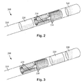
- Figures 2 and 3 illustrate embodiments of a distal portion of a lead 200 for brain stimulation.
- the lead 200 includes a lead body 210, one or more optional ring electrodes 220, a plurality of segmented electrodes 230, and a tip electrode 240. It will be understood that other lead embodiments can include only a tip electrode and one or more ring electrodes or only a tip electrode and one or more segmented electrodes. Other embodiments can include a tip electrode and a combination of ring and segmented electrodes in arrangements other than those illustrated in Figures 2 and 3 .
- the lead body 210 can be formed of a biocompatible, non-conducting material such as, for example, a polymeric material. Suitable polymeric materials include, but are not limited to, silicone, polyurethane, polyurea, polyurethane-urea, polyethylene, or the like.
- the lead 200 may be in contact with body tissue for extended periods of time.
- the lead 200 has a cross-sectional diameter of no more than 1.5 mm and may be in the range of 1 to 1.5 mm.
- the lead 200 has a length of at least 10 cm and the length of the lead 200 may be in the range of 25 to 70 cm.
- the electrodes 220, 230, 240 may be made using a metal, alloy, conductive oxide, or any other suitable conductive biocompatible material.
- suitable materials include, but are not limited to, platinum, platinum iridium alloy, iridium, titanium, tungsten, palladium, palladium rhodium, or the like.
- the electrodes are made of a material that is biocompatible and does not substantially corrode under expected operating conditions in the operating environment for the expected duration of use.
- Each of the electrodes 220, 230, 240 can either be used or unused (OFF).
- the electrode can be used as an anode or cathode and carry anodic or cathodic current.
- an electrode might be an anode for a period of time and a cathode for a period of time.
- Stimulation electrodes in the form of ring electrodes 220 may be disposed on any part of the lead body 210, usually near a distal end of the lead 200.
- a stimulation electrode in the form of tip electrode 240 is disposed at the distal end of the lead.
- the lead 200 includes one ring electrode 220 and one tip electrode 240. Any number of ring electrodes 220 may be disposed along the length of the lead body 210 including, for example, one, two three, four, five, six, seven, eight, nine, ten, eleven, twelve, thirteen, fourteen, fifteen, sixteen or more ring electrodes 220. It will be understood that any number of ring electrodes may be disposed along the length of the lead body 210.
- the ring electrode(s) 220 and tip electrode 240 are substantially cylindrical and wrap around the entire circumference of the lead body 210.
- the tip electrode 240 also extends over the tip of the lead.
- the outer diameters of the ring electrode(s) 220 and tip electrode 240 are independently substantially equal to the outer diameter of the lead body 210.
- the length of the ring electrode(s) 220 and tip electrode 240 may independently vary according to the desired treatment and the location of the target neurons or other tissue. In some embodiments the length of one or more of the ring electrode(s) 220 and tip electrode 240 are less than or equal to the corresponding diameters of the ring electrode(s) 220 and tip electrode 240.
- the lengths of one or more of the ring electrode(s) 220 and tip electrode are greater than the corresponding diameters of the ring electrode(s) 220 and tip electrode 240.
- the surface area of the tip electrode 240 and one of the ring electrode(s) 220 may be equal of substantially equal (e.g., within 10% or 5% of each other).
- Deep brain stimulation leads and other leads may include one or more sets of segmented electrodes. Segmented electrodes may provide for superior current steering than ring electrodes because target structures in deep brain stimulation are not typically symmetric about the axis of the distal electrode array. Instead, a target may be located on one side of a plane running through the axis of the lead.
- RSEA radially segmented electrode array
- current steering can be performed not only along a length of the lead but also around a circumference of the lead. This provides precise three-dimensional targeting and delivery of the current stimulus to neural target tissue, while potentially avoiding stimulation of other tissue. Examples of leads with segmented electrodes include U.S. Patents Nos.
- the lead 200 is shown having a plurality of segmented electrodes 230.
- Any number of segmented electrodes 230 may be disposed on the lead body 210 including, for example, one, two three, four, five, six, seven, eight, nine, ten, eleven, twelve, thirteen, fourteen, fifteen, sixteen or more segmented electrodes 230. It will be understood that any number of segmented electrodes 230 may be disposed along the length of the lead body 210.
- the segmented electrodes 230 may be grouped into sets of segmented electrodes, where each set is disposed around a circumference of the lead 200 at a particular longitudinal portion of the lead 200.
- the lead 200 may have any number of segmented electrodes 230 in a given set of segmented electrodes.
- the lead 200 may have one, two, three, four, five, six, seven, eight, or more segmented electrodes 230 in a given set.
- each set of segmented electrodes 230 of the lead 200 contains the same number of segmented electrodes 230.
- the segmented electrodes 230 disposed on the lead 200 may include a different number of electrodes than at least one other set of segmented electrodes 230 disposed on the lead 200.
- the segmented electrodes 230 may vary in size and shape. In some embodiments, the segmented electrodes 230 are all of the same size, shape, diameter, width or area or any combination thereof. In some embodiments, the segmented electrodes 230 of each circumferential set (or even all segmented electrodes disposed on the lead 200) may be identical in size and shape.
- Each set of segmented electrodes 230 may be disposed around the circumference of the lead body 210 to form a substantially cylindrical shape around the lead body 210.
- the spacing between individual electrodes of a given set of the segmented electrodes may be the same, or different from, the spacing between individual electrodes of another set of segmented electrodes on the lead 200.
- equal spaces, gaps or cutouts are disposed between each segmented electrode 230 around the circumference of the lead body 210.
- the spaces, gaps or cutouts between the segmented electrodes 230 may differ in size or shape.
- the spaces, gaps, or cutouts between segmented electrodes 230 may be uniform for a particular set of the segmented electrodes 230, or for all sets of the segmented electrodes 230.
- the sets of segmented electrodes 230 may be positioned in irregular or regular intervals along a length the lead body 210.
- Conductor wires that attach to the tip electrode 240, ring electrode(s) 220, and segmented electrodes 230 extend along the lead body 210. These conductor wires may extend through the material of the lead 200 or along one or more lumens defined by the lead 200, or both. The conductor wires are presented at a connector (via terminals) for coupling of the electrodes 220, 230, 240 to a control unit (not shown).
- the ring electrodes 220 and the segmented electrodes 230 may be arranged in any suitable configuration.
- the tip electrode 240 will generally be at the distal tip of any arrangement containing a tip electrode 240.
- the tip electrode 240 and ring electrode 220 can flank the two sets of segmented electrodes 230 (see e.g., Figure 2 ).
- the tip electrode 240 and ring electrode 220 can be disposed distal to the two sets of segmented electrodes 230 (see e.g., Figure 3 ). It will be understood that other configurations are possible as well (e.g., alternating ring and segmented electrodes, or the like).
- tip electrode 240, ring electrodes 220, and segmented electrodes 230 may be disposed on the lead 200.
- the lead may include a ring electrode, two sets of segmented electrodes, each set formed of three segmented electrodes 230, and a tip electrode at the end of the lead.
- This configuration may simply be referred to as a 1-3-3-1 configuration as illustrated in Figure 2 . It may be useful to refer to the electrodes with this shorthand notation.
- Figure 3 illustrates a lead with a 3-3-1-1 configuration. Possible configurations for a 16-electrode lead with a tip electrode include, but are not limited to, 3-3-3-3-3-1 and 1-3-3-2-3-3-1.
- Markers or other indicia may be provided sot that the practitioner can determine the orientation of the segmented electrodes when implanted. Examples of suitable markers and indicia can be found in, for example, U.S. Patent Application Publications Nos. 2012/0016378 and 2012/0203321 and U.S. Patent Applications Serial Nos. 13/750,725 and 13/787,171 , all of which are incorporated herein by reference.
- Figure 4 is a schematic diagram to illustrate radial current steering along various electrode levels along the length of the lead 200. While conventional lead configurations with ring electrodes are only able to steer current along the length of the lead (the z -axis), the segmented electrode configuration is capable of steering current in the x-axis, y -axis as well as the z -axis. Thus, the centroid of stimulation may be steered in any direction in the three-dimensional space surrounding the lead 200. In some embodiments, the radial distance, r, and the angle ⁇ around the circumference of the lead 200 may be dictated by the percentage of anodic current (recognizing that stimulation predominantly occurs near the cathode, although strong anodes may cause stimulation as well) introduced to each electrode. In at least some embodiments, the configuration of anodes and cathodes along the segmented electrodes allows the centroid of stimulation to be shifted to a variety of different locations along the lead 200.
- the centroid of stimulation can be shifted at each level along the length of the lead 200.
- the use of multiple sets of segmented electrodes at different levels along the length of the lead allows for three-dimensional current steering.
- the sets of segmented electrodes are shifted collectively (i.e., the centroid of simulation is similar at each level along the length of the lead).
- each set of segmented electrodes is controlled independently.
- Each set of segmented electrodes may contain two, three, four, five, six, seven, eight or more segmented electrodes. It will be understood that different stimulation profiles may be produced by varying the number of segmented electrodes at each level.
- each set of segmented electrodes includes only two segmented electrodes, uniformly distributed gaps (inability to stimulate selectively) may be formed in the stimulation profile.
- at least three segmented electrodes 230 in a set are utilized to allow for true 360° selectivity.
- measurement devices coupled to the muscles or other tissues stimulated by the target neurons or a unit responsive to the patient or clinician can be coupled to the control unit or microdrive motor system.
- the measurement device, user, or clinician can indicate a response by the target muscles or other tissues to the stimulation or recording electrodes to further identify the target neurons and facilitate positioning of the stimulation electrodes.
- a measurement device can be used to observe the muscle and indicate changes in tremor frequency or amplitude in response to stimulation of neurons.
- the patient or clinician may observe the muscle and provide feedback.
- a tip electrode can be used in combination with one or more ring electrodes, one or more segmented electrodes, or any combination of ring and segmented electrodes.
- a tip electrode may be selected to have the same, or substantially the same, surface area as one or more ring electrodes of the lead.
- a tip electrode can be designed to improve retention of the tip electrode on the lead.
- a tip electrode may have a hollow cylindrical base and a separate plug that can be attached to the base.
- Figure 5 illustrates a tip electrode 540 having a base 542 and a separate plug 544.
- the base 542 and plug 544 are typically formed of a suitable metal, alloy, or other conductor.
- the base 542 is a hollow tubular structure with an interior lumen 541 with openings at opposing ends of the tubular structure that will allow material to flow through the base.
- the open interior lumen 541 facilitates retention of the base on the lead.
- the base 542 includes a distal opening 543 that is shaped to receive the plug 544.
- the base 542 will have sloped edges 545 at the distal opening 543 that correspond to sloped edges 547 on the plug 544 to facilitate mating of the base and plug. It will be understood that other configurations of the distal opening and corresponding surface on the plug can be used to facilitate mating of the base and plug.
- Figures 6A and 6B illustrate a distal portion of one embodiment of a lead 500 having a tip electrode 540 with a base 542 and a separate plug 544.
- the lead also includes a lead body 510, 510' and one or more additional electrodes 520.
- the lead body 510 is formed by molding the lead body 510' between the electrodes 520 (and, at least in some embodiments, between the electrodes and the terminals at the proximal end of the lead - see, Figure 1 ).
- the material of the lead body 510 can also be molded between the distal-most electrode 520 and the base 542 of the tip electrode 540.
- the material that will form the lead body can flow into the interior lumen 541 (see, Figure 5 ) of the base 542.
- Any molding process can be used including, but not limited to, injection molding.
- the lead body 510, 510' can be formed of any material that can be molded by flowing the material around the other components and then solidify the material to form the lead body.
- Any suitable process can be used to solidify the material including, but not limited to, cooling the material, photocuring, heat curing, crosslinking, and the like. Examples of suitable materials can include silicone, polyurethane, polyetheretherketone, and the like.
- the methods for forming a lead with segmented electrodes disclosed in U.S. Patent Application Publication No. 2011/0078900 can be modified to include a tip electrode(by, for example, replacing the distal-most ring electrode in Figures 7A-7E with a tip electrode).
- the lead body 510 When the lead body 510 is formed, the lead body will extend into the interior lumen of the base 542 and facilitate retention of the tip electrode 540 on the lead 500.
- the plug 544 can be attached (preferably, permanently) to the base 542 by, for example, welding, soldering, adhesive (preferably, conductive adhesive), press-fit, crimping, threading on the base and plug, or any combination thereof or any other suitable fastening arrangement.
- the plug 544 and base 542 are also in electrical communication with each through the fastening arrangement.
- a portion of the lead body may be removed from the distal opening 543 of the base 542 to allow attachment of the plug 544 to the base.
- a tip electrode conductor (not shown) is attached, welded, soldered, or otherwise electrically coupled to the tip electrode 540.
- the coupling of the tip electrode conductor may occur prior to forming the lead body 510.
- the tip electrode conductor like other conductors in the lead, extends along the lead and is electrically coupled to one of the terminals disposed along the proximal end of the lead.
- the tip electrode conductor is coupled to the base 542 at, for example, the surface of the interior lumen 541 or the proximal end of the base.
- the tip electrode conductor is attached to the plug 544.
- a tip electrode may include a stem with one or more features to facilitate retention of the tip electrode at the distal end of the lead.
- Figure 7 illustrates in cross-section one embodiment of a tip electrode 740 having an electrode body 742 and a stem 746 with shaped retention features 748 formed on the stem.
- the electrode body 742 includes at least a portion of the surface that is exposed to tissue, when the lead is implanted, for providing stimulation to the tissue.
- the material of the lead body forms around the stem of the tip electrode and facilitates retention of the tip electrodes within the lead body of the resulting lead.
- the shaped retention features 748 hinder extraction of the tip electrode from the lead body.
- the shaped retention features 748 on the stem typically extend away from the adjacent portions of the stem 746 to interact with material at the distal end of the lead, such as the lead body, to resist withdrawal of the tip electrode 740 from the distal end of the lead.
- suitable shaped retention features include, but are not limited to, one or more stepped features, sloped protrusions, flanges, teeth, protruding threads, or the like formed on the stem or a roughened surface formed on the stem.
- the shaped retention features have a sloping surface 760 on one side and a stepped surface 762 on the other side to resist withdrawal from the distal end of the lead.
- a tip electrode conductor (not shown) is attached, welded, soldered, or otherwise electrically coupled to the tip electrode 740.
- the tip electrode conductor is coupled to the stem 746.
- the tip electrode conductor could be coupled to the side of the stem 746 or the proximal end of the stem.
- the tip electrode conductor can be attached to the main portion of the tip electrode (i.e., the non-stem portion of the tip electrode).
- the tip electrode conductor extends along the lead and is electrically coupled to one of the terminals disposed along the proximal end of the lead.
- Figure 8A illustrates another embodiment of a tip electrode 840 that includes an electrode body 842 and a stem 846 with a flange 850 attached to the end of the stem.
- the electrode body 842 includes at least a portion of the surface that is exposed to tissue, when the lead is implanted, for providing stimulation to the tissue.
- the flange may have any suitable shape including, but not limited to, disc-shaped, square-shaped, hexagonal-shaped, octagonal-shaped, triangular-shaped, and the like.
- the flange is gear-shaped with a disc having regular indentations 852 formed in the sides of the disc leaving regular protrusions 854 around the edge of the disc.
- the tip electrode conductor (not shown) can be attached to any portion of the tip electrode including, but not limited to, the flange 850, the protrusions 854 of the flange, or the indentations 852 within the flange.
- the material of the lead body forms around the stem 846 and flange 850 of the tip electrode 840 which facilitates retention of the tip electrode within the lead body of the resulting lead.
- the flange 850 hinders extraction of the tip electrode 840 from the lead body.
- Portions of the lead body formed within the indentations 852 and around the protrusions 854 of the flange may facilitate both retention of the tip electrode on the lead and reduce the likelihood of rotation of the tip electrode.
- a non-circular flange will provide some resistance to rotation of the tip electrode.
- a pre-electrode 840' as illustrated in Figure 8B , is provided during manufacture.
- the lead body is formed around this pre-electrode 840'.
- the lead body and pre-electrode 840' are ground down to obtain the tip electrode 840 of Figure 8A . This grinding process also removes excess lead body material leaving the lead body at the desired diameter.
- Figure 9A illustrates an embodiment of a tip electrode 940 with an electrode body 942 and an interior lumen 941.
- the electrode body 942 includes at least a portion of the surface that is exposed to tissue, when the lead is implanted, for providing stimulation to the tissue.
- the material of the lead body flows into the interior lumen 941 to facilitate retention of the tip electrode on the lead body of the resulting lead.
- the tip electrode 940 defines protrusions 956 on the surface that defines the interior lumen 941. These protrusions 956 facilitate retaining the tip electrode on the lead body and also resist rotation of the tip electrode around the lead body.
- the pattern of protrusions 956 form a star shape in cross-section, but it will be recognized that outer regular and irregular shapes generated by protrusions into the interior lumen can be used to resist rotation of the tip electrode around the lead body.
- the proximal end of the tip electrode 940 defines a non-circular opening 958 with protrusions 956' that form a flange with respect to an adjacent portion 960 of the interior surface of tip electrode 940 defining the interior lumen 941.
- protrusions 956', and the resulting flange-like arrangement resist rotation of the tip electrode around the lead body and also resist removal of the tip electrode from the distal end of the lead.
- a tip electrode conductor (not shown) can be attached to any portion of the tip electrode including, but not limited to, the proximal end of the tip electrode, the protrusions 956', or the surface defining the interior lumen 941.
- a pre-electrode 940' as illustrated in Figure 9B , is provided during manufacture. The lead body is formed around, and within, this pre-electrode 940'. Then the lead body and pre-electrode 940' are ground down to obtain the tip electrode 940 of Figure 9A . This grinding process also removes excess lead body material leaving the lead body at the desired diameter. It will be understood that this embodiment can be modified to include a base with the interior lumen and a separate plug as illustrated in Figures 5-6B .
- Figure 10A illustrates an embodiment of a tip electrode 1040 with an electrode body 1042, an interior lumen 1041, and multiple arms 1060 extending from the electrode body 1042 and over the entrance 1064 to the interior lumen 1041.
- the electrode body 1042 includes at least a portion of the surface that is exposed to tissue, when the lead is implanted, for providing stimulation to the tissue.
- the material of the lead body flows into the interior lumen 941 to facilitates retention of the tip electrode within the lead body of the resulting lead.
- These arms 1060 facilitate retaining the tip electrode on the lead body and also resist rotation of the tip electrode around the lead body.
- tip electrode 1040 has three arms 1060, but it will be recognized that any number of arms can be used including, but not limited to, one, two, thee, four, six, or more arms.
- the arms 1060 can be distributed around the edge of the electrode body 1042 in any regular or irregular arrangement.
- the tip electrode conductor (not shown) can be attached to any portion of the tip electrode including, but not limited to, the proximal end of the tip electrode, the arms 1060, or the surface defining the interior lumen 1041.
- a pre-electrode 1040' as illustrated in Figure 10B , is provided during manufacture.
- the lead body is formed around, and within, this pre-electrode 1040'.
- the lead body and pre-electrode 1040' are ground down to obtain the tip electrode 1040 of Figure 10A .
- This grinding process also removes excess lead body material leaving the lead body at the desired diameter.
- this embodiment can be modified to include a base with the interior lumen and arms and a separate plug as illustrated in Figures 5-6B .
Abstract
Description
- This application claims the benefit of
U.S. Provisional Patent Application Serial No. 61/654,579 filed on June 1, 2012 - The invention is directed to the area of electrical stimulation systems and methods of making and using the systems. The present invention is also directed to electrical stimulation leads with a tip electrode designed to facilitate retention of the tip electrode on the distal end of the lead, as well as methods of making and using the leads and electrical stimulation systems.
- Electrical stimulation can be useful for treating a variety of conditions. Deep brain stimulation can be useful for treating, for example, Parkinson's disease, dystonia, essential tremor, chronic pain, Huntington's Disease, levodopa-induced dyskinesias and rigidity, bradykinesia, epilepsy and seizures, eating disorders, and mood disorders. Typically, a lead with a stimulating electrode at or near a tip of the lead provides the stimulation to target neurons in the brain. Magnetic resonance imaging ("MRI") or computerized tomography ("CT") scans can provide a starting point for determining where the stimulating electrode should be positioned to provide the desired stimulus to the target neurons.
- After the lead is implanted into a patient's brain, electrical stimulus current can be delivered through selected electrodes on the lead to stimulate target neurons in the brain. Typically, the electrodes are formed into rings disposed on a distal portion of the lead. The stimulus current projects from the ring electrodes equally in every direction. Because of the ring shape of these electrodes, the stimulus current cannot be directed to one or more specific positions around the ring electrode (e.g., on one or more sides, or points, around the lead). Consequently, undirected stimulation may result in unwanted stimulation of neighboring neural tissue, potentially resulting in undesired side effects.
- One embodiment is an implantable electrical stimulation lead including a lead body having a distal portion, a distal tip, and a proximal portion; a plurality of electrodes disposed along the distal portion of the lead body; a plurality of terminals disposed along the proximal portion of the lead; and a plurality of conductors, each conductor electrically coupling at least one of the electrodes to at least one of the terminals. The plurality of electrodes includes a tip electrode disposed on the distal tip of the lead body. The tip electrode has a base and a separate plug attached to the base. The base defines an interior lumen closed at one end by the plug. A portion of the lead body extends into the interior lumen of the base.
- Another embodiment is an implantable electrical stimulation lead including a lead body having a distal portion, a distal tip, and a proximal portion; a plurality of electrodes disposed along the distal portion of the lead body; a plurality of terminals disposed along the proximal portion of the lead; and a plurality of conductors, each conductor electrically coupling at least one of the electrodes to at least one of the terminals. The plurality of electrodes includes a tip electrode disposed on the distal tip of the lead body. The tip electrode has an electrode body, a stem extending from the electrode body, and a plurality of shaped retention features extending from the stem. A portion of the lead body extends around the stem and shaped retention features. The shaped retention features facilitate retention of the tip electrode on the lead body.
- Yet another embodiment is an implantable electrical stimulation lead including a lead body having a distal portion, a distal tip, and a proximal portion; a plurality of electrodes disposed along the distal portion of the lead body; a plurality of terminals disposed along the proximal portion of the lead; and a plurality of conductors, each conductor electrically coupling at least one of the electrodes to at least one of the terminals. The plurality of electrodes includes a tip electrode disposed on the distal tip of the lead body. The tip electrode has an electrode body, a stem extending from the electrode, body, and a flange attached to the stem opposite the electrode body. A portion of the lead body extends around the stem and flange. The flange facilitates retention of the tip electrode on the lead body.
- A further embodiment is an implantable electrical stimulation lead including a lead body having a distal portion, a distal tip, and a proximal portion; a plurality of electrodes disposed along the distal portion of the lead body; a plurality of terminals disposed along the proximal portion of the lead; and a plurality of conductors, each conductor electrically coupling at least one of the electrodes to at least one of the terminals. The plurality of electrodes includes a tip electrode disposed on the distal tip of the lead body. The tip electrode has an electrode body and the electrode body defines an interior lumen and a plurality of protrusions extending into the interior lumen. A portion of the lead body extends into the interior lumen of the electrode body. The plurality of protrusions in the interior lumen facilitates retention of the tip electrode on the lead body and hinders rotation of the tip electrode around the distal tip of the lead body.
- Another embodiment is an implantable electrical stimulation lead including a lead body comprising a distal portion, a distal tip, and a proximal portion; a plurality of electrodes disposed along the distal portion of the lead body; a plurality of terminals disposed along the proximal portion of the lead; and a plurality of conductors, each conductor electrically coupling at least one of the electrodes to at least one of the terminals. The plurality of electrodes includes a tip electrode disposed on the distal tip of the lead body. The tip electrode has an electrode body and a plurality of arms extending from the electrode body. The electrode body defines an interior lumen and an opening to the interior lumen. The plurality of arms extends over the opening to the interior lumen. A portion of the lead body extends into the interior lumen of the electrode body and around the plurality of arms. The plurality of arms facilitates retention of the tip electrode on the lead body.
- The following aspects are preferred embodiments of the invention:
- 1. An implantable electrical stimulation lead, comprising:
- a lead body comprising a distal portion, a distal tip, and a proximal portion; and
- a plurality of electrodes disposed along the distal portion of the lead body, the plurality of electrodes comprising a tip electrode disposed on the distal tip of the lead body, the tip electrode having a base and a separate plug attached to the base, wherein the base defines an interior lumen closed at one end by the plug, wherein a portion of the lead body extends into the interior lumen of the base;
- a plurality of terminals disposed along the proximal portion of the lead; and
- a plurality of conductors, each conductor electrically coupling at least one of the electrodes to at least one of the terminals.
- 2. The implantable electrical stimulation lead of aspect 1, wherein the base is in electrical communication with the plug.
- 3. The implantable electrical stimulation lead of aspect 1, wherein the plurality of electrodes further comprises a plurality of segmented electrodes.
- 4. The implantable electrical stimulation lead of aspect 3, wherein the plurality of electrodes further comprises at least one ring electrode.
- 5. An implantable electrical stimulation lead, comprising:
- a lead body comprising a distal portion, a distal tip, and a proximal portion;
- a plurality of electrodes disposed along the distal portion of the lead body, the plurality of electrodes comprising a tip electrode disposed on the distal tip of the lead body, the tip electrode having an electrode body, a stem extending from the electrode body, and a plurality of shaped retention features extending from the stem, wherein a portion of the lead body extends around the stem and shaped retention features, wherein the shaped retention features facilitate retention of the tip electrode on the lead body;
- a plurality of terminals disposed along the proximal portion of the lead; and
- a plurality of conductors, each conductor electrically coupling at least one of the electrodes to at least one of the terminals.
- 6. The implantable electrical stimulation lead of aspect 5, wherein the plurality of shaped retention features comprises at least one shaped retention feature having a sloped edge on one side and a stepped edge on an opposite side.
- 7. The implantable electrical stimulation lead of aspect 5, wherein the plurality of shaped retention features comprises at least one protruding thread.
- 8. The implantable electrical stimulation lead of aspect 5, wherein the plurality of shaped retention features comprises at least one stepped feature.
- 9. An implantable electrical stimulation lead, comprising:
- a lead body comprising a distal portion, a distal tip, and a proximal portion;
- a plurality of electrodes disposed along the distal portion of the lead body, the plurality of electrodes comprising a tip electrode disposed on the distal tip of the lead body, the tip electrode having an electrode body, a stem extending from the electrode body, and a flange attached to the stem opposite the electrode body, wherein a portion of the lead body extends around the stem and flange, wherein the flange facilitates retention of the tip electrode on the lead body;
- a plurality of terminals disposed along the proximal portion of the lead; and
- a plurality of conductors, each conductor electrically coupling at least one of the electrodes to at least one of the terminals.
- 10. The implantable electrical stimulation lead of aspect 9, wherein the flange is non-circular and resists rotation of the tip electrode around the distal tip of the lead body.
- 11. The implantable electrical stimulation lead of claim 10, wherein the flange comprises a plurality of indentations.
- 12. The implantable electrical stimulation lead of claim 11, wherein the plurality of conductors comprises a tip electrode conductor coupled to the flange of the tip electrode at one of the plurality of indentations.
- 13. An implantable electrical stimulation lead, comprising:
- a lead body comprising a distal portion, a distal tip, and a proximal portion;
- a plurality of electrodes disposed along the distal portion of the lead body, the plurality of electrodes comprising a tip electrode disposed on the distal tip of the lead body, the tip electrode having an electrode body, wherein the electrode body defines an interior lumen and a plurality of protrusions extending into the interior lumen, wherein a portion of the lead body extends into the interior lumen of the electrode body and wherein the plurality of protrusions in the interior lumen facilitates retention of the tip electrode on the lead body and hinders rotation of the tip electrode around the distal tip of the lead body;
- a plurality of terminals disposed along the proximal portion of the lead; and
- a plurality of conductors, each conductor electrically coupling at least one of the electrodes to at least one of the terminals.
- 14. The implantable electrical stimulation lead of
aspect 13, wherein the electrode body further defines an opening to the interior lumen with a plurality of protrusions formed around the opening to give the opening a non-circular shape. - 15. The implantable electrical stimulation lead of aspect 14, wherein the plurality of protrusions formed around the opening provide a flange-like arrangement with respect to an adjacent surface of the interior lumen.
- 16. The implantable electrical stimulation lead of
aspect 13, wherein the electrode body further comprises a base and a separate plug attached to the base. - 17. An implantable electrical stimulation lead, comprising:
- a lead body comprising a distal portion, a distal tip, and a proximal portion;
- a plurality of electrodes disposed along the distal portion of the lead body, the plurality of electrodes comprising a tip electrode disposed on the distal tip of the lead body, the tip electrode having an electrode body and a plurality of arms extending from the electrode body, wherein the electrode body defines an interior lumen and an opening to the interior lumen and wherein the plurality of arms extends over the opening to the interior lumen, wherein a portion of the lead body extends into the interior lumen of the electrode body and around the plurality of arms, wherein the plurality of arms facilitates retention of the tip electrode on the lead body;
- a plurality of terminals disposed along the proximal portion of the lead; and
- a plurality of conductors, each conductor electrically coupling at least one of the electrodes to at least one of the terminals.
- 18. The implantable electrical stimulation lead of aspect 17, wherein the arms are placed at regular intervals around the electrode body.
- 19. The implantable electrical stimulation lead of aspect 17, wherein the plurality of electrodes further comprises a plurality of segmented electrodes.
- 20. The implantable electrical stimulation lead of aspect 17, wherein the electrode body further comprises a base and a separate plug attached to the base.
- Non-limiting and non-exhaustive embodiments of the present invention are described with reference to the following drawings. In the drawings, like reference numerals refer to like parts throughout the various figures unless otherwise specified.
- For a better understanding of the present invention, reference will be made to the following Detailed Description, which is to be read in association with the accompanying drawings, wherein:
-
FIG. 1 is a schematic side view of one embodiment of a device for brain stimulation, according to the invention; -
FIG. 2 is a schematic perspective view of one embodiment of a portion of a lead having a plurality of segmented electrodes and a tip electrode, according to the invention; -
FIG. 3 is a schematic perspective view of a second embodiment of a portion of a lead having a plurality of segmented electrodes and a tip electrode, according to the invention; -
FIG. 4 is a schematic diagram of radial current steering along various electrode levels along the length of a lead, according to the invention; -
FIG. 5 is a schematic cross-sectional view of one embodiment of a two piece tip electrode, according to the invention; -
FIG. 6A is a schematic side view of an embodiment of a portion of a lead with a two-piece tip electrode prior to coupling of the two pieces together, according to the invention; -
FIG. 6B is a schematic side view of the portion of the lead ofFigure 6A with the two pieces of the tip electrode coupled together, according to the invention; -
FIG. 7 is a schematic cross-sectional view of one embodiment of a tip electrode with a stem, according to the invention; -
FIG. 8A is a schematic perspective view of one embodiment of a tip electrode with a stem and flange, according to the invention; -
FIG. 8B is a schematic perspective view of one embodiment of a pre-electrode that can be ground down to form the tip electrode ofFigure 8A , according to the invention; -
FIG. 9A is a schematic perspective view of one embodiment of a tip electrode with a shaped interior lumen, according to the invention; -
FIG. 9B is a schematic perspective view of one embodiment of a pre-electrode that can be ground down to form the tip electrode ofFigure 9A , according to the invention; -
FIG. 10A is a schematic perspective view of one embodiment of a tip electrode with an interior lumen and multiple arms extending from an edge of the electrode over the opening of the interior lumen, according to the invention; and -
FIG. 10B is a schematic perspective view of one embodiment of a pre-electrode that can be ground down to form the tip electrode ofFigure 10A , according to the invention. - The invention is directed to the area of electrical stimulation systems and methods of making and using the systems. The present invention is also directed to electrical stimulation leads with a tip electrode designed to facilitate retention of the tip electrode on the distal end of the lead, as well as methods of making and using the leads and electrical stimulation systems.
- A lead for deep brain stimulation may include stimulation electrodes, recording electrodes, or a combination of both. In at least some embodiments, the stimulation or recording electrodes of the lead can include a tip electrode and one or more ring electrodes or segmented electrodes or any combination thereof. In at least some embodiments, at least some of the stimulation electrodes, recording electrodes, or both are provided in the form of segmented electrodes that extend only partially around the circumference of the lead. In some embodiments, these segmented electrodes may be provided in sets of electrodes, with each set having electrodes radially distributed about the lead at a particular longitudinal position. In some embodiments, the segmented electrodes can be provided in any other suitable arrangement including, for example, arranging segmented electrodes in one or more helices around the circumference of the lead or arranging segmented electrodes along only one side of the lead.
- A practitioner may determine the position of the target neurons using the recording electrode(s) and then position the stimulation electrode(s) accordingly without removal of a recording lead and insertion of a stimulation lead. In some embodiments, the same electrodes can be used for both recording and stimulation. In some embodiments, separate leads can be used; one with recording electrodes which identify target neurons, and a second lead with stimulation electrodes that replaces the first after target neuron identification. A lead may include recording electrodes spaced around the circumference of the lead to more precisely determine the position of the target neurons. In at least some embodiments, the lead is rotatable so that the stimulation electrodes can be aligned with the target neurons after the neurons have been located using the recording electrodes. For illustrative purposes, the leads are described herein relative to use for deep brain stimulation, but it will be understood that any of the leads can be used for applications other than deep brain stimulation including, but not limited to, spinal cord stimulation, dorsal root ganglion stimulation, and stimulation of other nerves, muscle tissue, or organs.
- Deep brain stimulation devices and leads are described in, for example,
U.S. Patent No. 7,809,446 ; andU.S. Patent Application Publications Nos. 2007/0150036 ;2009/0187222 ;2009/0276021 ;2010/0076535 ;2010/0268298 ; and2011/0078900 ; andU.S. Patent Applications Serial Nos. 12/177,823 ;61/022,953 61/316,759 -
Figure 1 illustrates one embodiment of adevice 100 for brain stimulation. The device includes alead 110, a plurality ofelectrodes 125 disposed at least partially about a circumference of thelead 110, a plurality ofterminals 135, aconnector 130 for connection of the electrodes to a control unit, and astylet 140 for assisting in insertion and positioning of the lead in the patient's brain. Thestylet 140 can be made of a rigid material. Examples of suitable materials for the stylet include, but are not limited to, tungsten, stainless steel, and plastic. Thestylet 140 may have ahandle 150 to assist insertion into thelead 110, as well as rotation of thestylet 140 and lead 110. Theconnector 130 fits over a proximal end of thelead 110, preferably after removal of thestylet 140. - The control unit (not shown) is typically an implantable pulse generator that can be implanted into a patient's body, for example, below the patient's clavicle area. The pulse generator can have eight stimulation channels which may be independently programmable to control the magnitude of the current stimulus from each channel. In some cases the pulse generator may have more than eight stimulation channels (e.g., 16-, 32-, or more stimulation channels). The control unit may have one, two, three, four, or more connector ports, for receiving the plurality of
terminals 135 at the proximal end of thelead 110. - In one example of operation, access to the desired position in the brain can be accomplished by drilling a hole in the patient's skull or cranium with a cranial drill (commonly referred to as a burr), and coagulating and incising the dura mater, or brain covering. The
lead 110 can be inserted into the cranium and brain tissue with the assistance of thestylet 140. Thelead 110 can be guided to the target location within the brain using, for example, a stereotactic frame and a microdrive motor system. In some embodiments, the microdrive motor system can be fully or partially automatic. The microdrive motor system may be configured to perform one or more the following actions (alone or in combination): insert thelead 110, retract thelead 110, or rotate thelead 110. - In some embodiments, measurement devices coupled to the muscles or other tissues stimulated by the target neurons, or a unit responsive to the patient or clinician, can be coupled to the control unit or microdrive motor system. The measurement device, user, or clinician can indicate a response by the target muscles or other tissues to the stimulation or recording electrode(s) to further identify the target neurons and facilitate positioning of the stimulation electrode(s). For example, if the target neurons are directed to a muscle experiencing tremors, a measurement device can be used to observe the muscle and indicate changes in tremor frequency or amplitude in response to stimulation of neurons. Alternatively, the patient or clinician may observe the muscle and provide feedback.
- The
lead 110 for deep brain stimulation can include stimulation electrodes, recording electrodes, or both. In at least some embodiments, thelead 110 is rotatable so that the stimulation electrodes can be aligned with the target neurons after the neurons have been located using the recording electrodes. - Stimulation electrodes may be disposed on the circumference of the
lead 110 to stimulate the target neurons. Stimulation electrodes may be ring-shaped so that current projects from each electrode equally in every direction from the position of the electrode along a length of thelead 110. Ring electrodes, however, typically do not enable stimulus current to be directed to only one side of the lead. Segmented electrodes, however, can be used to direct stimulus current to one side, or even a portion of one side, of the lead. When segmented electrodes are used in conjunction with an implantable pulse generator that delivers constant current stimulus, current steering can be achieved to more precisely deliver the stimulus to a position around an axis of the lead (i. e. , radial positioning around the axis of the lead). - To achieve current steering, segmented electrodes can be utilized in addition to, or as an alternative to, ring electrodes. Though the following description discusses stimulation electrodes, it will be understood that all configurations of the stimulation electrodes discussed may be utilized in arranging recording electrodes as well.
-
Figures 2 and 3 illustrate embodiments of a distal portion of alead 200 for brain stimulation. Thelead 200 includes alead body 210, one or moreoptional ring electrodes 220, a plurality ofsegmented electrodes 230, and atip electrode 240. It will be understood that other lead embodiments can include only a tip electrode and one or more ring electrodes or only a tip electrode and one or more segmented electrodes. Other embodiments can include a tip electrode and a combination of ring and segmented electrodes in arrangements other than those illustrated inFigures 2 and 3 . - The
lead body 210 can be formed of a biocompatible, non-conducting material such as, for example, a polymeric material. Suitable polymeric materials include, but are not limited to, silicone, polyurethane, polyurea, polyurethane-urea, polyethylene, or the like. Once implanted in the body, thelead 200 may be in contact with body tissue for extended periods of time. In at least some embodiments, thelead 200 has a cross-sectional diameter of no more than 1.5 mm and may be in the range of 1 to 1.5 mm. In at least some embodiments, thelead 200 has a length of at least 10 cm and the length of thelead 200 may be in the range of 25 to 70 cm. - The
electrodes - Each of the
electrodes - Stimulation electrodes in the form of
ring electrodes 220 may be disposed on any part of thelead body 210, usually near a distal end of thelead 200. A stimulation electrode in the form oftip electrode 240 is disposed at the distal end of the lead. InFigure 2 , thelead 200 includes onering electrode 220 and onetip electrode 240. Any number ofring electrodes 220 may be disposed along the length of thelead body 210 including, for example, one, two three, four, five, six, seven, eight, nine, ten, eleven, twelve, thirteen, fourteen, fifteen, sixteen ormore ring electrodes 220. It will be understood that any number of ring electrodes may be disposed along the length of thelead body 210. - In some embodiments, the ring electrode(s) 220 and
tip electrode 240 are substantially cylindrical and wrap around the entire circumference of thelead body 210. Thetip electrode 240 also extends over the tip of the lead. In some embodiments, the outer diameters of the ring electrode(s) 220 andtip electrode 240 are independently substantially equal to the outer diameter of thelead body 210. The length of the ring electrode(s) 220 andtip electrode 240 may independently vary according to the desired treatment and the location of the target neurons or other tissue. In some embodiments the length of one or more of the ring electrode(s) 220 andtip electrode 240 are less than or equal to the corresponding diameters of the ring electrode(s) 220 andtip electrode 240. In other embodiments, the lengths of one or more of the ring electrode(s) 220 and tip electrode are greater than the corresponding diameters of the ring electrode(s) 220 andtip electrode 240. In at least some embodiments, the surface area of thetip electrode 240 and one of the ring electrode(s) 220 may be equal of substantially equal (e.g., within 10% or 5% of each other). - Deep brain stimulation leads and other leads may include one or more sets of segmented electrodes. Segmented electrodes may provide for superior current steering than ring electrodes because target structures in deep brain stimulation are not typically symmetric about the axis of the distal electrode array. Instead, a target may be located on one side of a plane running through the axis of the lead. Through the use of a radially segmented electrode array ("RSEA"), current steering can be performed not only along a length of the lead but also around a circumference of the lead. This provides precise three-dimensional targeting and delivery of the current stimulus to neural target tissue, while potentially avoiding stimulation of other tissue. Examples of leads with segmented electrodes include
U.S. Patents Nos. 8,295,944 ; and8,391,985 ; andU.S. Patent Applications Publication Nos. 2010/0268298 ;2011/0005069 ;2011/0078900 ;2011/0130817 ;2011/0130818 ;2011/0238129 ;2011/0313500 ;2012/0016378 ;2012/0046710 ;2012/0165911 ;2012/0197375 ;2012/0203316 ;2012/0203320 ; and2012/0203321 , all of which are incorporated herein by reference. - In
Figure 2 , thelead 200 is shown having a plurality ofsegmented electrodes 230. Any number ofsegmented electrodes 230 may be disposed on thelead body 210 including, for example, one, two three, four, five, six, seven, eight, nine, ten, eleven, twelve, thirteen, fourteen, fifteen, sixteen or moresegmented electrodes 230. It will be understood that any number ofsegmented electrodes 230 may be disposed along the length of thelead body 210. - The
segmented electrodes 230 may be grouped into sets of segmented electrodes, where each set is disposed around a circumference of thelead 200 at a particular longitudinal portion of thelead 200. Thelead 200 may have any number ofsegmented electrodes 230 in a given set of segmented electrodes. Thelead 200 may have one, two, three, four, five, six, seven, eight, or moresegmented electrodes 230 in a given set. In at least some embodiments, each set ofsegmented electrodes 230 of thelead 200 contains the same number ofsegmented electrodes 230. Thesegmented electrodes 230 disposed on thelead 200 may include a different number of electrodes than at least one other set ofsegmented electrodes 230 disposed on thelead 200. - The
segmented electrodes 230 may vary in size and shape. In some embodiments, thesegmented electrodes 230 are all of the same size, shape, diameter, width or area or any combination thereof. In some embodiments, thesegmented electrodes 230 of each circumferential set (or even all segmented electrodes disposed on the lead 200) may be identical in size and shape. - Each set of
segmented electrodes 230 may be disposed around the circumference of thelead body 210 to form a substantially cylindrical shape around thelead body 210. The spacing between individual electrodes of a given set of the segmented electrodes may be the same, or different from, the spacing between individual electrodes of another set of segmented electrodes on thelead 200. In at least some embodiments, equal spaces, gaps or cutouts are disposed between eachsegmented electrode 230 around the circumference of thelead body 210. In other embodiments, the spaces, gaps or cutouts between thesegmented electrodes 230 may differ in size or shape. In other embodiments, the spaces, gaps, or cutouts betweensegmented electrodes 230 may be uniform for a particular set of thesegmented electrodes 230, or for all sets of thesegmented electrodes 230. The sets ofsegmented electrodes 230 may be positioned in irregular or regular intervals along a length thelead body 210. - Conductor wires that attach to the
tip electrode 240, ring electrode(s) 220, andsegmented electrodes 230 extend along thelead body 210. These conductor wires may extend through the material of thelead 200 or along one or more lumens defined by thelead 200, or both. The conductor wires are presented at a connector (via terminals) for coupling of theelectrodes - When the
lead 200 includes atip electrode 240, ring electrode(s) 220 andsegmented electrodes 230, thering electrodes 220 and thesegmented electrodes 230 may be arranged in any suitable configuration. Thetip electrode 240 will generally be at the distal tip of any arrangement containing atip electrode 240. For example, when thelead 200 includes atip electrode 240, aring electrode 220 and two sets ofsegmented electrodes 230, thetip electrode 240 andring electrode 220 can flank the two sets of segmented electrodes 230 (see e.g.,Figure 2 ). Alternately, thetip electrode 240 andring electrode 220 can be disposed distal to the two sets of segmented electrodes 230 (see e.g.,Figure 3 ). It will be understood that other configurations are possible as well (e.g., alternating ring and segmented electrodes, or the like). - Any combination of
tip electrode 240,ring electrodes 220, andsegmented electrodes 230 may be disposed on thelead 200. For example, the lead may include a ring electrode, two sets of segmented electrodes, each set formed of threesegmented electrodes 230, and a tip electrode at the end of the lead. This configuration may simply be referred to as a 1-3-3-1 configuration as illustrated inFigure 2 . It may be useful to refer to the electrodes with this shorthand notation.Figure 3 illustrates a lead with a 3-3-1-1 configuration. Possible configurations for a 16-electrode lead with a tip electrode include, but are not limited to, 3-3-3-3-3-1 and 1-3-3-2-3-3-1. - Markers or other indicia may be provided sot that the practitioner can determine the orientation of the segmented electrodes when implanted. Examples of suitable markers and indicia can be found in, for example,
U.S. Patent Application Publications Nos. 2012/0016378 and2012/0203321 andU.S. Patent Applications Serial Nos. 13/750,725 and13/787,171 -
Figure 4 is a schematic diagram to illustrate radial current steering along various electrode levels along the length of thelead 200. While conventional lead configurations with ring electrodes are only able to steer current along the length of the lead (the z-axis), the segmented electrode configuration is capable of steering current in the x-axis, y-axis as well as the z-axis. Thus, the centroid of stimulation may be steered in any direction in the three-dimensional space surrounding thelead 200. In some embodiments, the radial distance, r, and the angle θ around the circumference of thelead 200 may be dictated by the percentage of anodic current (recognizing that stimulation predominantly occurs near the cathode, although strong anodes may cause stimulation as well) introduced to each electrode. In at least some embodiments, the configuration of anodes and cathodes along the segmented electrodes allows the centroid of stimulation to be shifted to a variety of different locations along thelead 200. - As can be appreciated from
Figure 4 , the centroid of stimulation can be shifted at each level along the length of thelead 200. The use of multiple sets of segmented electrodes at different levels along the length of the lead allows for three-dimensional current steering. In some embodiments, the sets of segmented electrodes are shifted collectively (i.e., the centroid of simulation is similar at each level along the length of the lead). In at least some other embodiments, each set of segmented electrodes is controlled independently. Each set of segmented electrodes may contain two, three, four, five, six, seven, eight or more segmented electrodes. It will be understood that different stimulation profiles may be produced by varying the number of segmented electrodes at each level. For example, when each set of segmented electrodes includes only two segmented electrodes, uniformly distributed gaps (inability to stimulate selectively) may be formed in the stimulation profile. In some embodiments, at least threesegmented electrodes 230 in a set are utilized to allow for true 360° selectivity. - As previously indicated, the foregoing configurations may also be used while utilizing recording electrodes. In some embodiments, measurement devices coupled to the muscles or other tissues stimulated by the target neurons or a unit responsive to the patient or clinician can be coupled to the control unit or microdrive motor system. The measurement device, user, or clinician can indicate a response by the target muscles or other tissues to the stimulation or recording electrodes to further identify the target neurons and facilitate positioning of the stimulation electrodes. For example, if the target neurons are directed to a muscle experiencing tremors, a measurement device can be used to observe the muscle and indicate changes in tremor frequency or amplitude in response to stimulation of neurons. Alternatively, the patient or clinician may observe the muscle and provide feedback.
- A tip electrode can be used in combination with one or more ring electrodes, one or more segmented electrodes, or any combination of ring and segmented electrodes. In at least some embodiments, a tip electrode may be selected to have the same, or substantially the same, surface area as one or more ring electrodes of the lead.
- A tip electrode can be designed to improve retention of the tip electrode on the lead. For example, a tip electrode may have a hollow cylindrical base and a separate plug that can be attached to the base.
Figure 5 illustrates atip electrode 540 having a base 542 and aseparate plug 544. Thebase 542 and plug 544 are typically formed of a suitable metal, alloy, or other conductor. Thebase 542 is a hollow tubular structure with aninterior lumen 541 with openings at opposing ends of the tubular structure that will allow material to flow through the base. The openinterior lumen 541 facilitates retention of the base on the lead. Thebase 542 includes adistal opening 543 that is shaped to receive theplug 544. In some embodiments, thebase 542 will have slopededges 545 at thedistal opening 543 that correspond to slopededges 547 on theplug 544 to facilitate mating of the base and plug. It will be understood that other configurations of the distal opening and corresponding surface on the plug can be used to facilitate mating of the base and plug. -
Figures 6A and 6B illustrate a distal portion of one embodiment of a lead 500 having atip electrode 540 with abase 542 and aseparate plug 544. The lead also includes alead body 510, 510' and one or moreadditional electrodes 520. In at least some embodiments thelead body 510 is formed by molding the lead body 510' between the electrodes 520 (and, at least in some embodiments, between the electrodes and the terminals at the proximal end of the lead - see,Figure 1 ). The material of thelead body 510 can also be molded between thedistal-most electrode 520 and thebase 542 of thetip electrode 540. During the molding process, the material that will form the lead body can flow into the interior lumen 541 (see,Figure 5 ) of thebase 542. Any molding process can be used including, but not limited to, injection molding. Thelead body 510, 510' can be formed of any material that can be molded by flowing the material around the other components and then solidify the material to form the lead body. Any suitable process can be used to solidify the material including, but not limited to, cooling the material, photocuring, heat curing, crosslinking, and the like. Examples of suitable materials can include silicone, polyurethane, polyetheretherketone, and the like. As an example, the methods for forming a lead with segmented electrodes disclosed inU.S. Patent Application Publication No. 2011/0078900 , incorporated herein by reference, can be modified to include a tip electrode(by, for example, replacing the distal-most ring electrode in Figures 7A-7E with a tip electrode). - When the
lead body 510 is formed, the lead body will extend into the interior lumen of thebase 542 and facilitate retention of thetip electrode 540 on thelead 500. After thelead body 510 is formed, theplug 544 can be attached (preferably, permanently) to thebase 542 by, for example, welding, soldering, adhesive (preferably, conductive adhesive), press-fit, crimping, threading on the base and plug, or any combination thereof or any other suitable fastening arrangement. Preferably, theplug 544 andbase 542 are also in electrical communication with each through the fastening arrangement. In at least some embodiments, a portion of the lead body may be removed from thedistal opening 543 of the base 542 to allow attachment of theplug 544 to the base. - A tip electrode conductor (not shown) is attached, welded, soldered, or otherwise electrically coupled to the
tip electrode 540. The coupling of the tip electrode conductor may occur prior to forming thelead body 510. The tip electrode conductor, like other conductors in the lead, extends along the lead and is electrically coupled to one of the terminals disposed along the proximal end of the lead. In some embodiments, the tip electrode conductor is coupled to the base 542 at, for example, the surface of theinterior lumen 541 or the proximal end of the base. In some embodiments, the tip electrode conductor is attached to theplug 544. - A tip electrode may include a stem with one or more features to facilitate retention of the tip electrode at the distal end of the lead.
Figure 7 illustrates in cross-section one embodiment of atip electrode 740 having anelectrode body 742 and astem 746 with shaped retention features 748 formed on the stem. Theelectrode body 742 includes at least a portion of the surface that is exposed to tissue, when the lead is implanted, for providing stimulation to the tissue. When the lead body is formed, the material of the lead body forms around the stem of the tip electrode and facilitates retention of the tip electrodes within the lead body of the resulting lead. The shaped retention features 748 hinder extraction of the tip electrode from the lead body. The shaped retention features 748 on the stem typically extend away from the adjacent portions of thestem 746 to interact with material at the distal end of the lead, such as the lead body, to resist withdrawal of thetip electrode 740 from the distal end of the lead. Examples of suitable shaped retention features include, but are not limited to, one or more stepped features, sloped protrusions, flanges, teeth, protruding threads, or the like formed on the stem or a roughened surface formed on the stem. In the embodiment illustrated inFigure 7 , the shaped retention features have asloping surface 760 on one side and a steppedsurface 762 on the other side to resist withdrawal from the distal end of the lead. - A tip electrode conductor (not shown) is attached, welded, soldered, or otherwise electrically coupled to the
tip electrode 740. In some embodiments, the tip electrode conductor is coupled to thestem 746. For example, the tip electrode conductor could be coupled to the side of thestem 746 or the proximal end of the stem. In other embodiments, the tip electrode conductor can be attached to the main portion of the tip electrode (i.e., the non-stem portion of the tip electrode). The tip electrode conductor extends along the lead and is electrically coupled to one of the terminals disposed along the proximal end of the lead. -
Figure 8A illustrates another embodiment of atip electrode 840 that includes anelectrode body 842 and astem 846 with aflange 850 attached to the end of the stem. Theelectrode body 842 includes at least a portion of the surface that is exposed to tissue, when the lead is implanted, for providing stimulation to the tissue. The flange may have any suitable shape including, but not limited to, disc-shaped, square-shaped, hexagonal-shaped, octagonal-shaped, triangular-shaped, and the like. In the illustrated embodiment, the flange is gear-shaped with a disc havingregular indentations 852 formed in the sides of the disc leavingregular protrusions 854 around the edge of the disc. The tip electrode conductor (not shown) can be attached to any portion of the tip electrode including, but not limited to, theflange 850, theprotrusions 854 of the flange, or theindentations 852 within the flange. - When the lead body is formed, the material of the lead body forms around the
stem 846 andflange 850 of thetip electrode 840 which facilitates retention of the tip electrode within the lead body of the resulting lead. Theflange 850 hinders extraction of thetip electrode 840 from the lead body. Portions of the lead body formed within theindentations 852 and around theprotrusions 854 of the flange may facilitate both retention of the tip electrode on the lead and reduce the likelihood of rotation of the tip electrode. Typically, a non-circular flange will provide some resistance to rotation of the tip electrode. - In at least some embodiments, a pre-electrode 840', as illustrated in
Figure 8B , is provided during manufacture. The lead body is formed around this pre-electrode 840'. Then the lead body and pre-electrode 840' are ground down to obtain thetip electrode 840 ofFigure 8A . This grinding process also removes excess lead body material leaving the lead body at the desired diameter. -
Figure 9A illustrates an embodiment of atip electrode 940 with anelectrode body 942 and aninterior lumen 941. Theelectrode body 942 includes at least a portion of the surface that is exposed to tissue, when the lead is implanted, for providing stimulation to the tissue. When the lead body is formed, the material of the lead body flows into theinterior lumen 941 to facilitate retention of the tip electrode on the lead body of the resulting lead. Thetip electrode 940 definesprotrusions 956 on the surface that defines theinterior lumen 941. Theseprotrusions 956 facilitate retaining the tip electrode on the lead body and also resist rotation of the tip electrode around the lead body. In the illustrated embodiment, the pattern ofprotrusions 956 form a star shape in cross-section, but it will be recognized that outer regular and irregular shapes generated by protrusions into the interior lumen can be used to resist rotation of the tip electrode around the lead body. - In addition, the proximal end of the
tip electrode 940 defines anon-circular opening 958 with protrusions 956' that form a flange with respect to anadjacent portion 960 of the interior surface oftip electrode 940 defining theinterior lumen 941. These protrusions 956', and the resulting flange-like arrangement, resist rotation of the tip electrode around the lead body and also resist removal of the tip electrode from the distal end of the lead. - A tip electrode conductor (not shown) can be attached to any portion of the tip electrode including, but not limited to, the proximal end of the tip electrode, the protrusions 956', or the surface defining the
interior lumen 941. In at least some embodiments, a pre-electrode 940', as illustrated inFigure 9B , is provided during manufacture. The lead body is formed around, and within, this pre-electrode 940'. Then the lead body and pre-electrode 940' are ground down to obtain thetip electrode 940 ofFigure 9A . This grinding process also removes excess lead body material leaving the lead body at the desired diameter. It will be understood that this embodiment can be modified to include a base with the interior lumen and a separate plug as illustrated inFigures 5-6B . -
Figure 10A illustrates an embodiment of atip electrode 1040 with anelectrode body 1042, aninterior lumen 1041, andmultiple arms 1060 extending from theelectrode body 1042 and over theentrance 1064 to theinterior lumen 1041. Theelectrode body 1042 includes at least a portion of the surface that is exposed to tissue, when the lead is implanted, for providing stimulation to the tissue. When the lead body is formed, the material of the lead body flows into theinterior lumen 941 to facilitates retention of the tip electrode within the lead body of the resulting lead. Thesearms 1060 facilitate retaining the tip electrode on the lead body and also resist rotation of the tip electrode around the lead body. In the illustrated embodiment,tip electrode 1040 has threearms 1060, but it will be recognized that any number of arms can be used including, but not limited to, one, two, thee, four, six, or more arms. Thearms 1060 can be distributed around the edge of theelectrode body 1042 in any regular or irregular arrangement. - The tip electrode conductor (not shown) can be attached to any portion of the tip electrode including, but not limited to, the proximal end of the tip electrode, the
arms 1060, or the surface defining theinterior lumen 1041. In at least some embodiments, a pre-electrode 1040', as illustrated inFigure 10B , is provided during manufacture. The lead body is formed around, and within, this pre-electrode 1040'. Then the lead body and pre-electrode 1040' are ground down to obtain thetip electrode 1040 ofFigure 10A . This grinding process also removes excess lead body material leaving the lead body at the desired diameter. It will be understood that this embodiment can be modified to include a base with the interior lumen and arms and a separate plug as illustrated inFigures 5-6B . - The above specification, examples, and data provide a description of the manufacture and use of the composition of the invention. Since many embodiments of the invention can be made without departing from the spirit and scope of the invention, the invention also resides in the claims hereinafter appended.
Claims (15)
- An implantable electrical stimulation lead, comprising:a lead body comprising a distal portion, a distal tip, and a proximal portion;a plurality of electrodes disposed along the distal portion of the lead body, the plurality of electrodes comprising a tip electrode disposed on the distal tip of the lead body, the tip electrode having an electrode body, wherein the electrode body defines an interior lumen and a plurality of protrusions extending into the interior lumen, wherein a portion of the lead body extends into the interior lumen of the electrode body and wherein the plurality of protrusions in the interior lumen facilitates retention of the tip electrode on the lead body and hinders rotation of the tip electrode around the distal tip of the lead body;a plurality of terminals disposed along the proximal portion of the lead; anda plurality of conductors, each conductor electrically coupling at least one of the electrodes to at least one of the terminals.
- The implantable electrical stimulation lead of claim 1, wherein the electrode body further defines an opening to the interior lumen with a plurality of protrusions formed around the opening to give the opening a non-circular shape.
- The implantable electrical stimulation lead of claim 2, wherein the plurality of protrusions formed around the opening provide a flange-like arrangement with respect to an adjacent surface of the interior lumen.
- The implantable electrical stimulation lead of claim 1, wherein the electrode body further comprises a base and a separate plug attached to the base.
- The implantable electrical stimulation lead of claim 1, wherein two or more of the protrusions are arranged in a ring around a circumference of the interior lumen of the electrode body.
- The implantable electrical stimulation lead of claim 1, wherein a plurality of the plurality of protrusions are arranged in a plurality of concentric rings around a circumference of the interior lumen of the electrode body.
- The implantable electrical stimulation lead of claim 1, wherein the plurality of electrodes further comprises a plurality of segmented electrodes.
- The implantable electrical stimulation lead of claim 7, wherein the plurality of electrodes further comprises at least one ring electrode.
- The implantable electrical stimulation lead of claim 1, the plurality of protrusions form a star shape in cross-section.
- The implantable electrical stimulation lead of claim 1, wherein the tip electrode further comprises a plurality of arms extending from the base and extending over the opening to the interior lumen, wherein a portion of the lead body extends around the plurality of arms, wherein the plurality of arms facilitates retention of the tip electrode on the lead body.
- The implantable electrical stimulation lead of claim 10, wherein the arms are placed at regular intervals around the base.
- An implantable electrical stimulation lead, comprising:a lead body comprising a distal portion, a distal tip, and a proximal portion;a plurality of electrodes disposed along the distal portion of the lead body, the plurality of electrodes comprising a tip electrode disposed on the distal tip of the lead body, the tip electrode having an electrode body and a plurality of arms extending from the electrode body, wherein the electrode body defines an interior lumen and an opening to the interior lumen and wherein the plurality of arms extends over the opening to the interior lumen, wherein a portion of the lead body extends into the interior lumen of the electrode body and around the plurality of arms, wherein the plurality of arms facilitates retention of the tip electrode on the lead body;a plurality of terminals disposed along the proximal portion of the lead; anda plurality of conductors, each conductor electrically coupling at least one of the electrodes to at least one of the terminals.
- The implantable electrical stimulation lead of claim 12, wherein the arms are placed at regular intervals around the electrode body.
- The implantable electrical stimulation lead of claim 12, wherein the plurality of electrodes further comprises a plurality of segmented electrodes.
- The implantable electrical stimulation lead of claim 12, wherein the electrode body further comprises a base and a separate plug attached to the base.
Applications Claiming Priority (3)
| Application Number | Priority Date | Filing Date | Title |
|---|---|---|---|
| US201261654579P | 2012-06-01 | 2012-06-01 | |
| EP13729559.8A EP2854936B1 (en) | 2012-06-01 | 2013-05-31 | Leads with tip electrode for electrical stimulation systems and methods of making and using |
| PCT/US2013/043588 WO2013181519A2 (en) | 2012-06-01 | 2013-05-31 | Leads with tip electrode for electrical stimulation systems and methods of making and using |
Related Parent Applications (2)
| Application Number | Title | Priority Date | Filing Date |
|---|---|---|---|
| EP13729559.8A Division-Into EP2854936B1 (en) | 2012-06-01 | 2013-05-31 | Leads with tip electrode for electrical stimulation systems and methods of making and using |
| EP13729559.8A Division EP2854936B1 (en) | 2012-06-01 | 2013-05-31 | Leads with tip electrode for electrical stimulation systems and methods of making and using |
Publications (2)
| Publication Number | Publication Date |
|---|---|
| EP3111989A1 true EP3111989A1 (en) | 2017-01-04 |
| EP3111989B1 EP3111989B1 (en) | 2021-09-01 |
Family
ID=48628939
Family Applications (2)
| Application Number | Title | Priority Date | Filing Date |
|---|---|---|---|
| EP13729559.8A Active EP2854936B1 (en) | 2012-06-01 | 2013-05-31 | Leads with tip electrode for electrical stimulation systems and methods of making and using |
| EP16165920.6A Active EP3111989B1 (en) | 2012-06-01 | 2013-05-31 | Leads with tip electrode for electrical stimulation systems |
Family Applications Before (1)
| Application Number | Title | Priority Date | Filing Date |
|---|---|---|---|
| EP13729559.8A Active EP2854936B1 (en) | 2012-06-01 | 2013-05-31 | Leads with tip electrode for electrical stimulation systems and methods of making and using |
Country Status (7)
| Country | Link |
|---|---|
| US (2) | US8792993B2 (en) |
| EP (2) | EP2854936B1 (en) |
| JP (2) | JP5926453B2 (en) |
| CN (1) | CN104519946B (en) |
| AU (1) | AU2013267240B2 (en) |
| ES (1) | ES2585260T3 (en) |
| WO (1) | WO2013181519A2 (en) |
Families Citing this family (129)
| Publication number | Priority date | Publication date | Assignee | Title |
|---|---|---|---|---|
| US7860570B2 (en) | 2002-06-20 | 2010-12-28 | Boston Scientific Neuromodulation Corporation | Implantable microstimulators and methods for unidirectional propagation of action potentials |
| US8321025B2 (en) | 2006-07-31 | 2012-11-27 | Cranial Medical Systems, Inc. | Lead and methods for brain monitoring and modulation |
| EP3536376A1 (en) | 2008-07-30 | 2019-09-11 | Ecole Polytechnique Fédérale de Lausanne | Apparatus for optimized stimulation of a neurological target |
| US8359107B2 (en) | 2008-10-09 | 2013-01-22 | Boston Scientific Neuromodulation Corporation | Electrode design for leads of implantable electric stimulation systems and methods of making and using |
| JP5667987B2 (en) | 2008-11-12 | 2015-02-12 | エコーレ ポリテクニーク フェデラーレ デ ローザンヌ (イーピーエフエル) | Micromachined nerve stimulation device |
| EP3520855A1 (en) | 2009-04-16 | 2019-08-07 | Boston Scientific Neuromodulation Corporation | Deep brain stimulation current steering with split electrodes |
| US8887387B2 (en) | 2009-07-07 | 2014-11-18 | Boston Scientific Neuromodulation Corporation | Methods of manufacture of leads with a radially segmented electrode array |
| US8875391B2 (en) | 2009-07-07 | 2014-11-04 | Boston Scientific Neuromodulation Corporation | Methods for making leads with radially-aligned segmented electrodes for electrical stimulation systems |
| US8788063B2 (en) * | 2009-11-30 | 2014-07-22 | Boston Scientific Neuromodulation Corporation | Electrode array having a rail system and methods of manufacturing the same |
| US8874232B2 (en) | 2009-11-30 | 2014-10-28 | Boston Scientific Neuromodulation Corporation | Electrode array having concentric split ring electrodes and methods of making the same |
| US9549708B2 (en) | 2010-04-01 | 2017-01-24 | Ecole Polytechnique Federale De Lausanne | Device for interacting with neurological tissue and methods of making and using the same |
| WO2011159631A2 (en) | 2010-06-18 | 2011-12-22 | Boston Scientific Neuromodulation Corporation | Electrode array having embedded electrodes and methods of making the same |
| US8583237B2 (en) | 2010-09-13 | 2013-11-12 | Cranial Medical Systems, Inc. | Devices and methods for tissue modulation and monitoring |
| WO2012039919A2 (en) | 2010-09-21 | 2012-03-29 | Boston Scientific Neuromodulation Corporation | Systems and methods for making and using radially-aligned segmented electrodes for leads of electrical stimulation systems |
| WO2012087416A1 (en) | 2010-12-23 | 2012-06-28 | Boston Scientific Neuromodulation Corporation | Methods for making leads with segmented electrodes for electrical stimulation systems |
| US8700179B2 (en) | 2011-02-02 | 2014-04-15 | Boston Scientific Neuromodulation Corporation | Leads with spiral of helical segmented electrode arrays and methods of making and using the leads |
| US20120203316A1 (en) | 2011-02-08 | 2012-08-09 | Boston Scientific Neuromodulation Corporation | Leads with segmented electrodes for electrical stimulation of planar regions and methods of making and using |
| CA2826036A1 (en) | 2011-02-08 | 2012-08-16 | Boston Scientific Neuromodulation Corporation | Leads with spirally arranged segmented electrodes and methods of making and using the leads |
| WO2013112905A1 (en) | 2012-01-26 | 2013-08-01 | Boston Scientific Neuromodulation Corporation | Systems and methods for identifying the circumferential positioning of electrodes of leads for electrical stimulation systems |
| WO2013148092A1 (en) | 2012-03-30 | 2013-10-03 | Boston Scientific Neuromodulation Corporation | Leads with x-ray fluorescent capsules for electrode identification and methods of manufacture and use |
| US9919148B2 (en) | 2012-05-25 | 2018-03-20 | Boston Scientific Neuromodulation Corporation | Distally curved electrical stimulation lead and methods of making and using |
| AU2013267240B2 (en) | 2012-06-01 | 2016-04-28 | Boston Scientific Neuromodulation Corporation | Leads with tip electrode for electrical stimulation systems and methods of making and using |
| US8897891B2 (en) | 2012-08-03 | 2014-11-25 | Boston Scientific Neuromodulation Corporation | Leads with electrode carrier for segmented electrodes and methods of making and using |
| CN105209111B (en) | 2013-03-15 | 2017-09-26 | 波士顿科学神经调制公司 | For delivering subthreshold value treatment to the system and method for patient |
| EP2996765B1 (en) | 2013-05-15 | 2019-06-26 | Boston Scientific Neuromodulation Corporation | Tip electrodes for leads of electrical stimulation systems |
| WO2014193762A2 (en) | 2013-05-31 | 2014-12-04 | Boston Scientific Neuromodulation Corporation | Leads containing segmented electrodes with non-perpendicular legs and methods of making and using |
| US9149630B2 (en) | 2013-05-31 | 2015-10-06 | Boston Scientific Neuromodulation Corporation | Segmented electrode leads formed from pre-electrodes with alignment features and methods of making and using the leads |
| EP3003465A1 (en) | 2013-05-31 | 2016-04-13 | Boston Scientific Neuromodulation Corporation | Segmented electrode leads formed from pre-electrodes with depressions or apertures and methods of making |
| WO2014193760A1 (en) | 2013-05-31 | 2014-12-04 | Boston Scientific Neuromodulation Corporation | Leads with segmented electrodes and methods of making the leads |
| US9289596B2 (en) | 2013-07-12 | 2016-03-22 | Boston Scientific Neuromodulation Corporation | Leads with segmented electrodes and methods of making and using the leads |
| US9566747B2 (en) | 2013-07-22 | 2017-02-14 | Boston Scientific Neuromodulation Corporation | Method of making an electrical stimulation lead |
| US9089689B2 (en) | 2013-08-30 | 2015-07-28 | Boston Scientific Neuromodulation Corporation | Methods of making segmented electrode leads using flanged carrier |
| EP3077039B1 (en) | 2013-12-02 | 2021-10-13 | Boston Scientific Neuromodulation Corporation | Methods for manufacture of electrical stimulation leads with helically arranged electrodes |
| US11311718B2 (en) | 2014-05-16 | 2022-04-26 | Aleva Neurotherapeutics Sa | Device for interacting with neurological tissue and methods of making and using the same |
| EP3476430B1 (en) | 2014-05-16 | 2020-07-01 | Aleva Neurotherapeutics SA | Device for interacting with neurological tissue |
| EP3154625B1 (en) | 2014-06-13 | 2018-09-26 | Boston Scientific Neuromodulation Corporation | Leads with electrode carriers for segmented electrodes and methods of making and using |
| US9474894B2 (en) | 2014-08-27 | 2016-10-25 | Aleva Neurotherapeutics | Deep brain stimulation lead |
| US9770598B2 (en) | 2014-08-29 | 2017-09-26 | Boston Scientific Neuromodulation Corporation | Systems and methods for making and using improved connector contacts for electrical stimulation systems |
| US9561362B2 (en) | 2014-11-10 | 2017-02-07 | Boston Scientific Neuromodulation Corporation | Systems and methods for making and using improved contact arrays for electrical stimulation systems |
| US9604068B2 (en) | 2014-11-10 | 2017-03-28 | Boston Scientific Neuromodulation Corporation | Systems and methods for making and using improved connector contacts for electrical stimulation systems |
| WO2016126558A1 (en) | 2015-02-06 | 2016-08-11 | Boston Scientific Neuromodulation Corporation | Systems with improved contact arrays for electrical stimulation systems |
| US9833611B2 (en) | 2015-04-10 | 2017-12-05 | Boston Scientific Neuromodulation Corporation | Systems and methods for making and using improved contact arrays for electrical stimulation systems |
| US9364659B1 (en) | 2015-04-27 | 2016-06-14 | Dantam K. Rao | Smart lead for deep brain stimulation |
| EP3280491B1 (en) | 2015-06-29 | 2023-03-01 | Boston Scientific Neuromodulation Corporation | Systems for selecting stimulation parameters by targeting and steering |
| EP3280490B1 (en) | 2015-06-29 | 2021-09-01 | Boston Scientific Neuromodulation Corporation | Systems for selecting stimulation parameters based on stimulation target region, effects, or side effects |
| US9656093B2 (en) | 2015-07-16 | 2017-05-23 | Boston Scientific Neuromodulation Corporation | Systems and methods for making and using connector contact arrays for electrical stimulation systems |
| EP3307382A1 (en) | 2015-08-24 | 2018-04-18 | Boston Scientific Neuromodulation Corporation | Systems and methods for determining orientation of an electrical stimulation lead |
| EP3297719B1 (en) | 2015-09-01 | 2022-02-09 | Boston Scientific Neuromodulation Corporation | Detection of lead orientation |
| US9956394B2 (en) | 2015-09-10 | 2018-05-01 | Boston Scientific Neuromodulation Corporation | Connectors for electrical stimulation systems and methods of making and using |
| US10413737B2 (en) | 2015-09-25 | 2019-09-17 | Boston Scientific Neuromodulation Corporation | Systems and methods for providing therapy using electrical stimulation to disrupt neuronal activity |
| WO2017062378A1 (en) | 2015-10-09 | 2017-04-13 | Boston Scientific Neuromodulation Corporation | System and methods for clinical effects mapping for directional stimulations leads |
| US10342983B2 (en) | 2016-01-14 | 2019-07-09 | Boston Scientific Neuromodulation Corporation | Systems and methods for making and using connector contact arrays for electrical stimulation systems |
| CN109069824B (en) | 2016-02-02 | 2022-09-16 | 阿莱瓦神经治疗股份有限公司 | Treatment of autoimmune diseases using deep brain stimulation |
| EP3411116B1 (en) | 2016-02-05 | 2020-01-22 | Boston Scientific Neuromodulation Corporation | Implantable optical stimulation lead |
| US10814127B2 (en) | 2016-02-05 | 2020-10-27 | Boston Scientific Neuromodulation Corporation | Slotted sleeve neurostimulation device |
| US10485969B2 (en) | 2016-02-19 | 2019-11-26 | Boston Scientific Neuromodulation Corporation | Electrical stimulation cuff devices and systems |
| US10716942B2 (en) | 2016-04-25 | 2020-07-21 | Boston Scientific Neuromodulation Corporation | System and methods for directional steering of electrical stimulation |
| WO2017201058A1 (en) | 2016-05-17 | 2017-11-23 | Boston Scientific Neuromodulation Corporation | Systems and methods for anchoring a lead for neurostimulation of a target anatomy |
| US10493269B2 (en) | 2016-06-02 | 2019-12-03 | Boston Scientific Neuromodulation Corporation | Leads for electrostimulation of peripheral nerves and other targets |
| US10201713B2 (en) | 2016-06-20 | 2019-02-12 | Boston Scientific Neuromodulation Corporation | Threaded connector assembly and methods of making and using the same |
| WO2017223505A2 (en) | 2016-06-24 | 2017-12-28 | Boston Scientific Neuromodulation Corporation | Systems and methods for visual analytics of clinical effects |
| US10307602B2 (en) | 2016-07-08 | 2019-06-04 | Boston Scientific Neuromodulation Corporation | Threaded connector assembly and methods of making and using the same |
| EP3452163A1 (en) | 2016-07-29 | 2019-03-13 | Boston Scientific Neuromodulation Corporation | Systems and methods for making and using an electrical stimulation system for peripheral nerve stimulation |
| WO2018039117A1 (en) | 2016-08-22 | 2018-03-01 | Boston Scientific Neuromodulation Corporation | Neuromodulation system for providing paresthesia and analgesia and a system with leads and with electrodes |
| WO2018044881A1 (en) | 2016-09-02 | 2018-03-08 | Boston Scientific Neuromodulation Corporation | Systems and methods for visualizing and directing stimulation of neural elements |
| US10780282B2 (en) | 2016-09-20 | 2020-09-22 | Boston Scientific Neuromodulation Corporation | Systems and methods for steering electrical stimulation of patient tissue and determining stimulation parameters |
| US10543374B2 (en) | 2016-09-30 | 2020-01-28 | Boston Scientific Neuromodulation Corporation | Connector assemblies with bending limiters for electrical stimulation systems and methods of making and using same |
| EP3493875B1 (en) | 2016-10-14 | 2020-05-27 | Boston Scientific Neuromodulation Corporation | Systems and methods for determining orientation of an implanted lead |
| AU2017341910B2 (en) | 2016-10-14 | 2020-05-14 | Boston Scientific Neuromodulation Corporation | Systems and methods for closed-loop determination of stimulation parameter settings for an electrical simulation system |
| WO2018071420A1 (en) | 2016-10-14 | 2018-04-19 | Boston Scientific Neuromodulation Corporation | Orientation marker for implantable leads, and leads and systems utilizing the orientation marker |
| US10625072B2 (en) | 2016-10-21 | 2020-04-21 | Boston Scientific Neuromodulation Corporation | Electrical stimulation methods with optical observation and devices therefor |
| US10716935B2 (en) | 2016-11-04 | 2020-07-21 | Boston Scientific Neuromodulation Corporation | Electrical stimulation leads, systems and methods for stimulation of dorsal root ganglia |
| US10603485B2 (en) | 2016-11-28 | 2020-03-31 | Boston Scientific Neuromodulation Corporation | Features in increased surface area on neuromodulation leads |
| WO2018102773A1 (en) | 2016-12-02 | 2018-06-07 | Boston Scientific Neuromodulation Corporation | Methods and systems for selecting stimulation parameters for electrical stimulation devices |
| US10576269B2 (en) | 2017-01-03 | 2020-03-03 | Boston Scientific Neuromodulation Corporation | Force-decoupled and strain relieving lead and methods of making and using |
| CA3045697C (en) | 2017-01-03 | 2021-07-20 | Boston Scientific Neuromodulation Corporation | Systems and methods for selecting mri-compatible stimulation parameters |
| US10589104B2 (en) | 2017-01-10 | 2020-03-17 | Boston Scientific Neuromodulation Corporation | Systems and methods for creating stimulation programs based on user-defined areas or volumes |
| EP3568196B1 (en) | 2017-01-10 | 2023-11-29 | Boston Scientific Neuromodulation Corporation | Patterned stimulation for deep brain stimulation |
| US10905871B2 (en) | 2017-01-27 | 2021-02-02 | Boston Scientific Neuromodulation Corporation | Lead assemblies with arrangements to confirm alignment between terminals and contacts |
| US10709886B2 (en) | 2017-02-28 | 2020-07-14 | Boston Scientific Neuromodulation Corporation | Electrical stimulation leads and systems with elongate anchoring elements and methods of making and using |
| US10814136B2 (en) | 2017-02-28 | 2020-10-27 | Boston Scientific Neuromodulation Corporation | Toolless connector for latching stimulation leads and methods of making and using |
| US10625082B2 (en) | 2017-03-15 | 2020-04-21 | Boston Scientific Neuromodulation Corporation | Visualization of deep brain stimulation efficacy |
| US10835739B2 (en) | 2017-03-24 | 2020-11-17 | Boston Scientific Neuromodulation Corporation | Electrical stimulation leads and systems with elongate anchoring elements and methods of making and using |
| WO2018187090A1 (en) | 2017-04-03 | 2018-10-11 | Boston Scientific Neuromodulation Corporation | Systems and methods for estimating a volume of activation using a compressed database of threshold values |
| US10603499B2 (en) | 2017-04-07 | 2020-03-31 | Boston Scientific Neuromodulation Corporation | Tapered implantable lead and connector interface and methods of making and using |
| US10631937B2 (en) | 2017-04-14 | 2020-04-28 | Boston Scientific Neuromodulation Corporation | Systems and methods for determining orientation of an implanted electrical stimulation lead |
| US10814140B2 (en) | 2017-06-26 | 2020-10-27 | Boston Scientific Neuromodulation Corporation | Systems and methods for visualizing and controlling optogenetic stimulation using optical stimulation systems |
| EP3651849B1 (en) | 2017-07-14 | 2023-05-31 | Boston Scientific Neuromodulation Corporation | Estimating clinical effects of electrical stimulation |
| WO2019014217A1 (en) | 2017-07-14 | 2019-01-17 | Boston Scientific Neuromodulation Corporation | Systems and methods for planning and programming electrical stimulation |
| EP3658228A1 (en) | 2017-07-25 | 2020-06-03 | Boston Scientific Neuromodulation Corporation | Systems and methods for making and using an enhanced connector of an electrical stimulation system |
| EP3634569A1 (en) | 2017-08-15 | 2020-04-15 | Boston Scientific Neuromodulation Corporation | Systems and methods for controlling electrical stimulation using multiple stimulation fields |
| US10639485B2 (en) | 2017-09-15 | 2020-05-05 | Boston Scientific Neuromodulation Corporation | Actuatable lead connector for an operating room cable assembly and methods of making and using |
| US11045656B2 (en) | 2017-09-15 | 2021-06-29 | Boston Scientific Neuromodulation Corporation | Biased lead connector for operating room cable assembly and methods of making and using |
| US11139603B2 (en) | 2017-10-03 | 2021-10-05 | Boston Scientific Neuromodulation Corporation | Connectors with spring contacts for electrical stimulation systems and methods of making and using same |
| US11103716B2 (en) | 2017-11-13 | 2021-08-31 | Boston Scientific Neuromodulation Corporation | Systems and methods for making and using a low-profile control module for an electrical stimulation system |
| EP3710103B1 (en) | 2017-11-17 | 2024-02-21 | Boston Scientific Neuromodulation Corporation | Systems for generating intermittent stimulation using electrical stimulation systems |
| WO2019139883A1 (en) | 2018-01-11 | 2019-07-18 | Boston Scientific Neuromodulation Corporation | Methods and systems for stimulation for glial modulation |
| US11103712B2 (en) | 2018-01-16 | 2021-08-31 | Boston Scientific Neuromodulation Corporation | Connector assemblies with novel spacers for electrical stimulation systems and methods of making and using same |
| US11497914B2 (en) | 2018-01-16 | 2022-11-15 | Boston Scientific Neuromodulation Corporation | Systems and methods for making and using an electrical stimulation system with a case-neutral battery |
| US10702692B2 (en) | 2018-03-02 | 2020-07-07 | Aleva Neurotherapeutics | Neurostimulation device |
| US11058870B2 (en) | 2018-03-09 | 2021-07-13 | Boston Scientific Neuromodulation Corporation | Burr hole plugs for electrical stimulation systems and methods of making and using |
| US11013913B2 (en) | 2018-03-16 | 2021-05-25 | Boston Scientific Neuromodulation Corporation | Kits and methods for securing a burr hole plugs for stimulation systems |
| US11565131B2 (en) | 2018-03-23 | 2023-01-31 | Boston Scientific Neuromodulation Corporation | Optical stimulation systems with calibration and methods of making and using |
| US20190290924A1 (en) | 2018-03-23 | 2019-09-26 | Boston Scientific Neuromodulation Corporation | Implantable prostheses for reducing visibility of bulging from implanted medical devices |
| US11524174B2 (en) | 2018-03-23 | 2022-12-13 | Boston Scientific Neuromodulation Corporation | Optical stimulation system with on-demand monitoring and methods of making and using |
| EP3784331B1 (en) | 2018-04-27 | 2023-01-18 | Boston Scientific Neuromodulation Corporation | Multi-mode electrical stimulation systems and methods of making and using |
| WO2019210214A1 (en) | 2018-04-27 | 2019-10-31 | Boston Scientific Neuromodulation Corporation | Systems for visualizing and programming electrical stimulation |
| US11172959B2 (en) | 2018-05-02 | 2021-11-16 | Boston Scientific Neuromodulation Corporation | Long, flexible sheath and lead blank and systems and methods of making and using |
| WO2019217415A1 (en) | 2018-05-11 | 2019-11-14 | Boston Scientific Neuromodulation Corporation | Connector assembly for an electrical stimulation system |
| EP3796966A1 (en) | 2018-07-09 | 2021-03-31 | Boston Scientific Neuromodulation Corporation | Directional electrical stimulation leads and systems for spinal cord stimulation |
| US11224743B2 (en) | 2018-09-21 | 2022-01-18 | Boston Scientific Neuromodulation Corporation | Systems and methods for making and using modular leads for electrical stimulation systems |
| EP3840824A1 (en) | 2018-11-16 | 2021-06-30 | Boston Scientific Neuromodulation Corporation | An optical stimulation system with on-demand monitoring and methods of making |
| US11167128B2 (en) | 2018-11-16 | 2021-11-09 | Boston Scientific Neuromodulation Corporation | Directional electrical stimulation leads, systems and methods for spinal cord stimulation |
| AU2020226356B2 (en) | 2019-02-19 | 2022-12-08 | Boston Scientific Neuromodulation Corporation | Lead introducers and systems and methods including the lead introducers |
| EP3946569B1 (en) | 2019-04-01 | 2023-11-15 | Boston Scientific Neuromodulation Corporation | Low-profile control module for an electrical stimulation system |
| US11357992B2 (en) | 2019-05-03 | 2022-06-14 | Boston Scientific Neuromodulation Corporation | Connector assembly for an electrical stimulation system and methods of making and using |
| WO2021086784A1 (en) | 2019-10-28 | 2021-05-06 | Boston Scientific Neuromodulation Corporation | Systems and methods for measuring temperature on or near an implantable medical device |
| US11806532B2 (en) * | 2019-11-26 | 2023-11-07 | Heraeus Medical Components Llc | Implantable lead with asymmetric fiducial marker |
| EP4076625A1 (en) | 2020-02-19 | 2022-10-26 | Boston Scientific Neuromodulation Corporation | Methods and systems for treatment of insomnia using deep brain stimulation |
| EP4168110A1 (en) | 2020-09-04 | 2023-04-26 | Boston Scientific Neuromodulation Corporation | Stimulation systems with a lens arrangement for light coupling and methods of making and using |
| US20220148591A1 (en) | 2020-11-11 | 2022-05-12 | Boston Scientific Neuromodulation Corporation | Voice command handler for programming stimulation systems and methods of using |
| JP2024508562A (en) | 2021-02-25 | 2024-02-27 | ボストン サイエンティフィック ニューロモデュレイション コーポレイション | Method and system for deep brain stimulation of basal ganglia of Meynert |
| EP4291294A1 (en) | 2021-04-27 | 2023-12-20 | Boston Scientific Neuromodulation Corporation | Systems and methods for automated programming of electrical stimulation |
| US20230181906A1 (en) | 2021-12-09 | 2023-06-15 | Boston Scientific Neuromodulation Corporation | Methods and systems for monitoring or assessing movement disorders or other physiological parameters using a stimulation system |
| WO2023107449A2 (en) | 2021-12-10 | 2023-06-15 | Boston Scientific Neuromodulation Corporation | Systems and methods for generating and using response maps for electrical stimulation |
| US20230181089A1 (en) | 2021-12-10 | 2023-06-15 | Boston Scientific Neuromodulation Corporation | Methods and systems for determining and using an intensity index for electrical stimulation |
| WO2023154346A1 (en) | 2022-02-10 | 2023-08-17 | Boston Scientific Neuromodulation Corporation | Automatic therapy adjustment based on sensors |
| WO2023163882A1 (en) | 2022-02-24 | 2023-08-31 | Boston Scientific Neuromodulation Corporation | Systems and methods for using cost parameters for programming electrical stimulation |
| WO2023167872A1 (en) | 2022-03-02 | 2023-09-07 | Boston Scientific Neuromodulation Corporation | Systems and methods for monitoring stimulation drift in an electrical stimulation system |
Citations (7)
| Publication number | Priority date | Publication date | Assignee | Title |
|---|---|---|---|---|
| US4844099A (en) * | 1986-11-24 | 1989-07-04 | Telectronics, N.V. | Porous pacemaker electrode tip using a porous substrate |
| US5230349A (en) * | 1988-11-25 | 1993-07-27 | Sensor Electronics, Inc. | Electrical heating catheter |
| US20100076535A1 (en) * | 2008-09-25 | 2010-03-25 | Boston Scientific Neuromodulation Corporation | Leads with non-circular-shaped distal ends for brain stimulation systems and methods of making and using |
| US20100268298A1 (en) * | 2009-04-16 | 2010-10-21 | Boston Scientific Neuromodulation Corporation | Deep brain stimulation current steering with split electrodes |
| US20110078900A1 (en) * | 2009-07-07 | 2011-04-07 | Boston Scientific Neuromodulation Corporation | Methods for making leads with radially-aligned segmented electrodes for electrical stimulation systems |
| US20110130817A1 (en) * | 2009-11-30 | 2011-06-02 | Boston Scientific Neuromodulation Corporation | Electrode array having a rail system and methods of manufacturing the same |
| US20140343647A1 (en) * | 2013-05-15 | 2014-11-20 | Boston Scientific Neuromodulation Corporation | Systems and methods for making and using tip electrodes for leads of electrical stimulation systems |
Family Cites Families (123)
| Publication number | Priority date | Publication date | Assignee | Title |
|---|---|---|---|---|
| US2295308A (en) | 1938-02-26 | 1942-09-08 | Gen Electric | High speed reclosing mechanism |
| US3942536A (en) * | 1971-03-15 | 1976-03-09 | Mieczyslaw Mirowski | Cardioverting device having single intravascular catheter electrode system and method for its use |
| US4413636A (en) * | 1979-11-19 | 1983-11-08 | Phillip R. Beutel | Catheter |
| US4630611A (en) | 1981-02-02 | 1986-12-23 | Medtronic, Inc. | Orthogonally-sensing lead |
| US4602624A (en) | 1984-10-11 | 1986-07-29 | Case Western Reserve University | Implantable cuff, method of manufacture, and method of installation |
| US4744370A (en) | 1987-04-27 | 1988-05-17 | Cordis Leads, Inc. | Lead assembly with selectable electrode connection |
| US5000194A (en) | 1988-08-25 | 1991-03-19 | Cochlear Corporation | Array of bipolar electrodes |
| US5097843A (en) * | 1990-04-10 | 1992-03-24 | Siemens-Pacesetter, Inc. | Porous electrode for a pacemaker |
| US5135001A (en) | 1990-12-05 | 1992-08-04 | C. R. Bard, Inc. | Ultrasound sheath for medical diagnostic instruments |
| WO1992021285A1 (en) * | 1991-05-24 | 1992-12-10 | Ep Technologies, Inc. | Combination monophasic action potential/ablation catheter and high-performance filter system |
| EP0580928A1 (en) | 1992-07-31 | 1994-02-02 | ARIES S.r.l. | A spinal electrode catheter |
| ZA948393B (en) | 1993-11-01 | 1995-06-26 | Polartechnics Ltd | Method and apparatus for tissue type recognition |
| US5458629A (en) | 1994-02-18 | 1995-10-17 | Medtronic, Inc. | Implantable lead ring electrode and method of making |
| US5458596A (en) * | 1994-05-06 | 1995-10-17 | Dorsal Orthopedic Corporation | Method and apparatus for controlled contraction of soft tissue |
| US5522874A (en) | 1994-07-28 | 1996-06-04 | Gates; James T. | Medical lead having segmented electrode |
| AU2067597A (en) | 1996-03-07 | 1997-09-22 | Axon Engineering, Inc. | Polymer-metal foil structure for neural stimulating electrodes |
| US5713922A (en) | 1996-04-25 | 1998-02-03 | Medtronic, Inc. | Techniques for adjusting the locus of excitation of neural tissue in the spinal cord or brain |
| US5711316A (en) | 1996-04-30 | 1998-01-27 | Medtronic, Inc. | Method of treating movement disorders by brain infusion |
| US5843148A (en) | 1996-09-27 | 1998-12-01 | Medtronic, Inc. | High resolution brain stimulation lead and method of use |
| US5938688A (en) | 1997-10-22 | 1999-08-17 | Cornell Research Foundation, Inc. | Deep brain stimulation method |
| US6161047A (en) | 1998-04-30 | 2000-12-12 | Medtronic Inc. | Apparatus and method for expanding a stimulation lead body in situ |
| US6134478A (en) | 1998-06-05 | 2000-10-17 | Intermedics Inc. | Method for making cardiac leads with zone insulated electrodes |
| US6064905A (en) | 1998-06-18 | 2000-05-16 | Cordis Webster, Inc. | Multi-element tip electrode mapping catheter |
| US6181969B1 (en) | 1998-06-26 | 2001-01-30 | Advanced Bionics Corporation | Programmable current output stimulus stage for implantable device |
| US6322559B1 (en) | 1998-07-06 | 2001-11-27 | Vnus Medical Technologies, Inc. | Electrode catheter having coil structure |
| US6018684A (en) | 1998-07-30 | 2000-01-25 | Cardiac Pacemakers, Inc. | Slotted pacing/shocking electrode |
| US6564078B1 (en) | 1998-12-23 | 2003-05-13 | Nuvasive, Inc. | Nerve surveillance cannula systems |
| ATE306213T1 (en) | 1998-12-23 | 2005-10-15 | Nuvasive Inc | DEVICES FOR CANNULATION AND NERVE MONITORING |
| US6393325B1 (en) | 1999-01-07 | 2002-05-21 | Advanced Bionics Corporation | Directional programming for implantable electrode arrays |
| US6167311A (en) | 1999-06-14 | 2000-12-26 | Electro Core Techniques, Llc | Method of treating psychological disorders by brain stimulation within the thalamus |
| US6516227B1 (en) | 1999-07-27 | 2003-02-04 | Advanced Bionics Corporation | Rechargeable spinal cord stimulator system |
| US7949395B2 (en) | 1999-10-01 | 2011-05-24 | Boston Scientific Neuromodulation Corporation | Implantable microdevice with extended lead and remote electrode |
| US6556873B1 (en) | 1999-11-29 | 2003-04-29 | Medtronic, Inc. | Medical electrical lead having variable bending stiffness |
| US6609029B1 (en) | 2000-02-04 | 2003-08-19 | Advanced Bionics Corporation | Clip lock mechanism for retaining lead |
| JP2003522004A (en) | 2000-02-09 | 2003-07-22 | トランスニューロニックス インコーポレイテッド | Medical implant device for electrical stimulation using individual microelectrodes |
| US6741892B1 (en) | 2000-03-10 | 2004-05-25 | Advanced Bionics Corporation | Movable contact locking mechanism for spinal cord stimulator lead connector |
| US6510347B2 (en) | 2000-08-17 | 2003-01-21 | William N. Borkan | Spinal cord stimulation leads |
| US6757970B1 (en) | 2000-11-07 | 2004-07-06 | Advanced Bionics Corporation | Method of making multi-contact electrode array |
| US7212867B2 (en) | 2000-12-07 | 2007-05-01 | Medtronic, Inc. | Directional brain stimulation and recording leads |
| GB0104982D0 (en) | 2001-02-28 | 2001-04-18 | Gill Steven | Electrode |
| US6766203B2 (en) | 2001-04-05 | 2004-07-20 | Pacesetter, Inc. | Body implantable lead with improved tip electrode assembly |
| US6678564B2 (en) | 2001-12-06 | 2004-01-13 | Advanced Cochlear Systems, Inc. | Bio-implant and method of making the same |
| WO2003063951A1 (en) | 2002-01-29 | 2003-08-07 | Advanced Bionics Corporation | Lead assembly for implantable microstimulator |
| US8000802B2 (en) | 2002-04-22 | 2011-08-16 | Medtronic, Inc. | Implantable lead with coplanar contact coupling |
| US7027852B2 (en) | 2002-05-21 | 2006-04-11 | Pacesetter, Inc. | Lead with distal tip surface electrodes connected in parallel |
| US7292890B2 (en) | 2002-06-20 | 2007-11-06 | Advanced Bionics Corporation | Vagus nerve stimulation via unidirectional propagation of action potentials |
| US7860570B2 (en) | 2002-06-20 | 2010-12-28 | Boston Scientific Neuromodulation Corporation | Implantable microstimulators and methods for unidirectional propagation of action potentials |
| US7177698B2 (en) | 2002-06-28 | 2007-02-13 | Advanced Bionics Corporation | Telemetry system for use with microstimulator |
| US7047084B2 (en) | 2002-11-20 | 2006-05-16 | Advanced Neuromodulation Systems, Inc. | Apparatus for directionally stimulating nerve tissue |
| US20050038489A1 (en) | 2003-08-14 | 2005-02-17 | Grill Warren M. | Electrode array for use in medical stimulation and methods thereof |
| WO2005053789A2 (en) | 2003-11-25 | 2005-06-16 | Advanced Neuromodulation Systems, Inc. | Directional stimulation lead and orientation system, and improved percutaneous-insertion needle and method of implanting a lead |
| US20050246007A1 (en) * | 2004-04-28 | 2005-11-03 | Medtronic, Inc. | Novel lead body assemblies |
| US7489971B1 (en) | 2004-06-05 | 2009-02-10 | Advanced Neuromodulation Systems, Inc. | Notched electrode for electrostimulation lead |
| EP1786509A4 (en) | 2004-07-27 | 2010-01-13 | Cleveland Clinic Foundation | Thalamic stimulation device |
| US20060041297A1 (en) * | 2004-08-23 | 2006-02-23 | Medtronic, Inc. | Novel electrode assembly for medical electrical leads |
| US7809446B2 (en) | 2005-01-05 | 2010-10-05 | Boston Scientific Neuromodulation Corporation | Devices and methods for brain stimulation |
| US8066702B2 (en) | 2005-01-11 | 2011-11-29 | Rittman Iii William J | Combination electrical stimulating and infusion medical device and method |
| ATE448830T1 (en) | 2005-01-31 | 2009-12-15 | Medtronic Inc | METHOD FOR PRODUCING A MEDICAL LINE |
| US8565898B2 (en) | 2005-04-28 | 2013-10-22 | Medtronic, Inc. | Rate control during AF using cellular intervention to modulate AV node |
| US7761165B1 (en) | 2005-09-29 | 2010-07-20 | Boston Scientific Neuromodulation Corporation | Implantable stimulator with integrated plastic housing/metal contacts and manufacture and use |
| US7672734B2 (en) | 2005-12-27 | 2010-03-02 | Boston Scientific Neuromodulation Corporation | Non-linear electrode array |
| US8700178B2 (en) | 2005-12-27 | 2014-04-15 | Boston Scientific Neuromodulation Corporation | Stimulator leads and methods for lead fabrication |
| US7244150B1 (en) | 2006-01-09 | 2007-07-17 | Advanced Bionics Corporation | Connector and methods of fabrication |
| US7822483B2 (en) | 2006-02-24 | 2010-10-26 | Medtronic, Inc. | Electrical and activation field models for configuring stimulation therapy |
| US7848802B2 (en) | 2006-02-24 | 2010-12-07 | Medtronic, Inc. | Programming interface with a concentric axial view of a stimulation lead with complex electrode array geometry |
| EP1993658B1 (en) | 2006-03-02 | 2009-10-07 | St Jude Medical AB | A medical implantable lead and a method for manufacturing of the same |
| US8175710B2 (en) | 2006-03-14 | 2012-05-08 | Boston Scientific Neuromodulation Corporation | Stimulator system with electrode array and the method of making the same |
| US7974706B2 (en) | 2006-03-30 | 2011-07-05 | Boston Scientific Neuromodulation Corporation | Electrode contact configurations for cuff leads |
| US7702387B2 (en) * | 2006-06-08 | 2010-04-20 | Greatbatch Ltd. | Tank filters adaptable for placement with a guide wire, in series with the lead wires or circuits of active medical devices to enhance MRI compatibility |
| US8321025B2 (en) | 2006-07-31 | 2012-11-27 | Cranial Medical Systems, Inc. | Lead and methods for brain monitoring and modulation |
| WO2008018067A2 (en) | 2006-08-07 | 2008-02-14 | Alpha Omega Engineering Ltd. | Cerebral electrodes and methods of operating same |
| US8224450B2 (en) | 2006-09-18 | 2012-07-17 | Boston Scientific Neuromodulation Corporation | Feed through interconnect assembly for an implantable stimulation system and methods of making and using |
| CN101516439B (en) | 2006-09-26 | 2013-09-11 | 沙皮恩斯脑部刺激控制有限公司 | Tissue stimulation method and appartus |
| EP2078263B1 (en) | 2006-10-31 | 2019-06-12 | Semiconductor Energy Laboratory Co, Ltd. | Semiconductor device |
| US20080103580A1 (en) | 2006-10-31 | 2008-05-01 | Medtronic, Inc. | Implantable medical elongated member with dual purpose conduit |
| US20080114230A1 (en) | 2006-11-14 | 2008-05-15 | Bruce Addis | Electrode support |
| US7979140B2 (en) | 2006-12-12 | 2011-07-12 | Alfred E. Mann Foundation For Scientific Research | Segmented electrode |
| EP2091606B1 (en) | 2006-12-13 | 2016-05-25 | Medtronic Bakken Research Center B.V. | First time right placement of a dbs lead |
| US7668601B2 (en) | 2007-04-26 | 2010-02-23 | Medtronic, Inc. | Implantable medical lead with multiple electrode configurations |
| EP2195081A1 (en) | 2007-08-20 | 2010-06-16 | Medtronic, INC. | Electrode configurations for directional leads |
| US9192409B2 (en) | 2008-01-23 | 2015-11-24 | Boston Scientific Neuromodulation Corporation | Steerable stylet handle assembly |
| US9220889B2 (en) | 2008-02-11 | 2015-12-29 | Intelect Medical, Inc. | Directional electrode devices with locating features |
| US8019440B2 (en) | 2008-02-12 | 2011-09-13 | Intelect Medical, Inc. | Directional lead assembly |
| US8600518B2 (en) | 2008-04-30 | 2013-12-03 | Boston Scientific Neuromodulation Corporation | Electrodes for stimulation leads and methods of manufacture and use |
| US20090319014A1 (en) | 2008-05-07 | 2009-12-24 | David Muecke | Lead assembly and related methods |
| US8688235B1 (en) | 2008-07-22 | 2014-04-01 | Boston Scientific Neuromodulation Corporation | Lead with transition and methods of manufacture and use |
| US8335551B2 (en) | 2008-09-29 | 2012-12-18 | Chong Il Lee | Method and means for connecting a large number of electrodes to a measuring device |
| US8359107B2 (en) | 2008-10-09 | 2013-01-22 | Boston Scientific Neuromodulation Corporation | Electrode design for leads of implantable electric stimulation systems and methods of making and using |
| JP5667987B2 (en) | 2008-11-12 | 2015-02-12 | エコーレ ポリテクニーク フェデラーレ デ ローザンヌ (イーピーエフエル) | Micromachined nerve stimulation device |
| US7974705B2 (en) | 2008-11-13 | 2011-07-05 | Proteus Biomedical, Inc. | Multiplexed multi-electrode neurostimulation devices |
| US9833616B2 (en) * | 2009-01-02 | 2017-12-05 | Medtronic, Inc. | System and method for cardiac lead |
| US8126557B2 (en) | 2009-02-13 | 2012-02-28 | Pacesetter, Inc. | Lead connector pin and body assembly and method of manufacture |
| US20100222860A1 (en) * | 2009-03-02 | 2010-09-02 | Pacesetter, Inc. | Implantable Leads Having Mechanisms to Impede Over-Rotation of Fixation Mechanisms |
| US8250755B2 (en) | 2009-04-24 | 2012-08-28 | Advanced Neuromodulation Systems, Inc. | Process for fabricating a medical lead |
| US8225504B2 (en) | 2009-04-24 | 2012-07-24 | Advanced Neuromodulation Systems, Inc. | Medical leads with segmented electrodes and methods of fabrication thereof |
| US8046909B2 (en) | 2009-04-24 | 2011-11-01 | Advanced Neuromodulation Systems, Inc. | Method of fabricating stimulation lead |
| US20100287770A1 (en) | 2009-05-14 | 2010-11-18 | Cochlear Limited | Manufacturing an electrode carrier for an implantable medical device |
| US8887387B2 (en) | 2009-07-07 | 2014-11-18 | Boston Scientific Neuromodulation Corporation | Methods of manufacture of leads with a radially segmented electrode array |
| WO2011028809A1 (en) | 2009-09-01 | 2011-03-10 | Advanced Neuromodulation Systems, Inc. | Medical leads with segmented electrodes and methods of fabrication thereof |
| US20110077699A1 (en) | 2009-09-30 | 2011-03-31 | John Swanson | Medical leads with segmented electrodes and methods of fabrication thereof |
| US8295944B2 (en) | 2009-11-30 | 2012-10-23 | Boston Scientific Neuromodulation Corporation | Electrode array with electrodes having cutout portions and methods of making the same |
| US8874232B2 (en) | 2009-11-30 | 2014-10-28 | Boston Scientific Neuromodulation Corporation | Electrode array having concentric split ring electrodes and methods of making the same |
| US8391985B2 (en) | 2009-11-30 | 2013-03-05 | Boston Scientific Neuromodulation Corporation | Electrode array having concentric windowed cylinder electrodes and methods of making the same |
| WO2011119377A1 (en) | 2010-03-23 | 2011-09-29 | Boston Scientific Neuromodulation Corporation | Helical radial spacing of contacts on a cylindrical lead |
| AU2011235161B2 (en) | 2010-04-02 | 2016-05-26 | Boston Scientific Neuromodulation Corporation | Directional lead assembly |
| WO2011159631A2 (en) | 2010-06-18 | 2011-12-22 | Boston Scientific Neuromodulation Corporation | Electrode array having embedded electrodes and methods of making the same |
| CA2803303A1 (en) | 2010-07-16 | 2012-01-19 | Boston Scientific Neuromodulation Corporation | Lead with marking stripes or a colored cable for identifying electrode positions |
| US20120046710A1 (en) | 2010-08-18 | 2012-02-23 | Boston Scientific Neuromodulation Corporation | Methods, systems, and devices for deep brain stimulation using helical movement of the centroid of stimulation |
| US8583237B2 (en) | 2010-09-13 | 2013-11-12 | Cranial Medical Systems, Inc. | Devices and methods for tissue modulation and monitoring |
| WO2012039919A2 (en) | 2010-09-21 | 2012-03-29 | Boston Scientific Neuromodulation Corporation | Systems and methods for making and using radially-aligned segmented electrodes for leads of electrical stimulation systems |
| WO2012087416A1 (en) | 2010-12-23 | 2012-06-28 | Boston Scientific Neuromodulation Corporation | Methods for making leads with segmented electrodes for electrical stimulation systems |
| US8700179B2 (en) | 2011-02-02 | 2014-04-15 | Boston Scientific Neuromodulation Corporation | Leads with spiral of helical segmented electrode arrays and methods of making and using the leads |
| CA2826036A1 (en) | 2011-02-08 | 2012-08-16 | Boston Scientific Neuromodulation Corporation | Leads with spirally arranged segmented electrodes and methods of making and using the leads |
| US20120203316A1 (en) | 2011-02-08 | 2012-08-09 | Boston Scientific Neuromodulation Corporation | Leads with segmented electrodes for electrical stimulation of planar regions and methods of making and using |
| CA2826040A1 (en) | 2011-02-08 | 2012-08-16 | Boston Scientific Neuromodulation Corporation | Methods for making leads with segmented electrodes for electrical stimulation systems |
| US9138576B2 (en) | 2011-10-28 | 2015-09-22 | Medtronic, Inc. | Lead end having inner support |
| WO2013112905A1 (en) | 2012-01-26 | 2013-08-01 | Boston Scientific Neuromodulation Corporation | Systems and methods for identifying the circumferential positioning of electrodes of leads for electrical stimulation systems |
| WO2013148092A1 (en) | 2012-03-30 | 2013-10-03 | Boston Scientific Neuromodulation Corporation | Leads with x-ray fluorescent capsules for electrode identification and methods of manufacture and use |
| EP2841149B1 (en) | 2012-04-27 | 2020-07-08 | Medtronic, Inc. | Method and system for fabricating a medical lead using an electrode fixture |
| AU2013266508A1 (en) | 2012-05-25 | 2014-11-06 | Boston Scientific Neuromodulation Corporation | Methods for stimulating the dorsal root ganglion with a lead having segmented electrodes |
| AU2013267240B2 (en) | 2012-06-01 | 2016-04-28 | Boston Scientific Neuromodulation Corporation | Leads with tip electrode for electrical stimulation systems and methods of making and using |
| WO2014018092A1 (en) | 2012-07-26 | 2014-01-30 | Medtronic, Inc. | Implantable medical leads |
| US8897891B2 (en) | 2012-08-03 | 2014-11-25 | Boston Scientific Neuromodulation Corporation | Leads with electrode carrier for segmented electrodes and methods of making and using |
-
2013
- 2013-05-31 AU AU2013267240A patent/AU2013267240B2/en active Active
- 2013-05-31 CN CN201380029009.9A patent/CN104519946B/en active Active
- 2013-05-31 JP JP2015515232A patent/JP5926453B2/en active Active
- 2013-05-31 EP EP13729559.8A patent/EP2854936B1/en active Active
- 2013-05-31 EP EP16165920.6A patent/EP3111989B1/en active Active
- 2013-05-31 WO PCT/US2013/043588 patent/WO2013181519A2/en active Application Filing
- 2013-05-31 ES ES13729559.8T patent/ES2585260T3/en active Active
- 2013-05-31 US US13/906,776 patent/US8792993B2/en active Active
-
2014
- 2014-06-13 US US14/304,688 patent/US8996132B2/en active Active
-
2016
- 2016-04-21 JP JP2016085376A patent/JP6189472B2/en active Active
Patent Citations (7)
| Publication number | Priority date | Publication date | Assignee | Title |
|---|---|---|---|---|
| US4844099A (en) * | 1986-11-24 | 1989-07-04 | Telectronics, N.V. | Porous pacemaker electrode tip using a porous substrate |
| US5230349A (en) * | 1988-11-25 | 1993-07-27 | Sensor Electronics, Inc. | Electrical heating catheter |
| US20100076535A1 (en) * | 2008-09-25 | 2010-03-25 | Boston Scientific Neuromodulation Corporation | Leads with non-circular-shaped distal ends for brain stimulation systems and methods of making and using |
| US20100268298A1 (en) * | 2009-04-16 | 2010-10-21 | Boston Scientific Neuromodulation Corporation | Deep brain stimulation current steering with split electrodes |
| US20110078900A1 (en) * | 2009-07-07 | 2011-04-07 | Boston Scientific Neuromodulation Corporation | Methods for making leads with radially-aligned segmented electrodes for electrical stimulation systems |
| US20110130817A1 (en) * | 2009-11-30 | 2011-06-02 | Boston Scientific Neuromodulation Corporation | Electrode array having a rail system and methods of manufacturing the same |
| US20140343647A1 (en) * | 2013-05-15 | 2014-11-20 | Boston Scientific Neuromodulation Corporation | Systems and methods for making and using tip electrodes for leads of electrical stimulation systems |
Also Published As
| Publication number | Publication date |
|---|---|
| EP2854936B1 (en) | 2016-05-25 |
| JP5926453B2 (en) | 2016-05-25 |
| US8996132B2 (en) | 2015-03-31 |
| JP2015517883A (en) | 2015-06-25 |
| WO2013181519A2 (en) | 2013-12-05 |
| US20130325091A1 (en) | 2013-12-05 |
| JP6189472B2 (en) | 2017-08-30 |
| EP3111989B1 (en) | 2021-09-01 |
| CN104519946B (en) | 2016-10-19 |
| EP2854936A2 (en) | 2015-04-08 |
| AU2013267240A1 (en) | 2014-11-27 |
| WO2013181519A3 (en) | 2014-03-27 |
| AU2013267240B2 (en) | 2016-04-28 |
| US20140296953A1 (en) | 2014-10-02 |
| CN104519946A (en) | 2015-04-15 |
| ES2585260T3 (en) | 2016-10-04 |
| US8792993B2 (en) | 2014-07-29 |
| JP2016129797A (en) | 2016-07-21 |
Similar Documents
| Publication | Publication Date | Title |
|---|---|---|
| EP2854936B1 (en) | Leads with tip electrode for electrical stimulation systems and methods of making and using | |
| US9775988B2 (en) | Electrical stimulation leads with helically arranged electrodes and methods of making and using | |
| US9248272B2 (en) | Segmented electrode leads formed from pre-electrodes with depressions or apertures and methods of making and using | |
| US9248275B2 (en) | Methods of making leads with retention features for segmented electrodes | |
| US9566747B2 (en) | Method of making an electrical stimulation lead | |
| EP3030309B1 (en) | Systems using segmented tip electrodes for leads of electrical simulation systems | |
| EP3003468B1 (en) | Methods for manufacturing segmented electrode leads using a removable ring and the leads formed thereby | |
| US9498620B2 (en) | Leads containing segmented electrodes with non-perpendicular legs and methods of making and using | |
| US9283375B2 (en) | Leads with segmented electrodes for electrical stimulation of planar regions and methods of making and using | |
| US20160121103A1 (en) | Electrical stimulation system with anchoring stylet and methods of making and using |
Legal Events
| Date | Code | Title | Description |
|---|---|---|---|
| PUAI | Public reference made under article 153(3) epc to a published international application that has entered the european phase |
Free format text: ORIGINAL CODE: 0009012 |
|
| STAA | Information on the status of an ep patent application or granted ep patent |
Free format text: STATUS: REQUEST FOR EXAMINATION WAS MADE |
|
| 17P | Request for examination filed |
Effective date: 20160519 |
|
| AC | Divisional application: reference to earlier application |
Ref document number: 2854936 Country of ref document: EP Kind code of ref document: P |
|
| AK | Designated contracting states |
Kind code of ref document: A1 Designated state(s): AL AT BE BG CH CY CZ DE DK EE ES FI FR GB GR HR HU IE IS IT LI LT LU LV MC MK MT NL NO PL PT RO RS SE SI SK SM TR |
|
| GRAP | Despatch of communication of intention to grant a patent |
Free format text: ORIGINAL CODE: EPIDOSNIGR1 |
|
| STAA | Information on the status of an ep patent application or granted ep patent |
Free format text: STATUS: GRANT OF PATENT IS INTENDED |
|
| INTG | Intention to grant announced |
Effective date: 20210430 |
|
| GRAS | Grant fee paid |
Free format text: ORIGINAL CODE: EPIDOSNIGR3 |
|
| GRAA | (expected) grant |
Free format text: ORIGINAL CODE: 0009210 |
|
| STAA | Information on the status of an ep patent application or granted ep patent |
Free format text: STATUS: THE PATENT HAS BEEN GRANTED |
|
| AC | Divisional application: reference to earlier application |
Ref document number: 2854936 Country of ref document: EP Kind code of ref document: P |
|
| AK | Designated contracting states |
Kind code of ref document: B1 Designated state(s): AL AT BE BG CH CY CZ DE DK EE ES FI FR GB GR HR HU IE IS IT LI LT LU LV MC MK MT NL NO PL PT RO RS SE SI SK SM TR |
|
| REG | Reference to a national code |
Ref country code: GB Ref legal event code: FG4D |
|
| REG | Reference to a national code |
Ref country code: CH Ref legal event code: EP Ref country code: AT Ref legal event code: REF Ref document number: 1425559 Country of ref document: AT Kind code of ref document: T Effective date: 20210915 |
|
| REG | Reference to a national code |
Ref country code: DE Ref legal event code: R096 Ref document number: 602013079129 Country of ref document: DE |
|
| REG | Reference to a national code |
Ref country code: IE Ref legal event code: FG4D |
|
| REG | Reference to a national code |
Ref country code: LT Ref legal event code: MG9D |
|
| REG | Reference to a national code |
Ref country code: NL Ref legal event code: MP Effective date: 20210901 |
|
| PG25 | Lapsed in a contracting state [announced via postgrant information from national office to epo] |
Ref country code: NO Free format text: LAPSE BECAUSE OF FAILURE TO SUBMIT A TRANSLATION OF THE DESCRIPTION OR TO PAY THE FEE WITHIN THE PRESCRIBED TIME-LIMIT Effective date: 20211201 Ref country code: FI Free format text: LAPSE BECAUSE OF FAILURE TO SUBMIT A TRANSLATION OF THE DESCRIPTION OR TO PAY THE FEE WITHIN THE PRESCRIBED TIME-LIMIT Effective date: 20210901 Ref country code: ES Free format text: LAPSE BECAUSE OF FAILURE TO SUBMIT A TRANSLATION OF THE DESCRIPTION OR TO PAY THE FEE WITHIN THE PRESCRIBED TIME-LIMIT Effective date: 20210901 Ref country code: BG Free format text: LAPSE BECAUSE OF FAILURE TO SUBMIT A TRANSLATION OF THE DESCRIPTION OR TO PAY THE FEE WITHIN THE PRESCRIBED TIME-LIMIT Effective date: 20211201 Ref country code: LT Free format text: LAPSE BECAUSE OF FAILURE TO SUBMIT A TRANSLATION OF THE DESCRIPTION OR TO PAY THE FEE WITHIN THE PRESCRIBED TIME-LIMIT Effective date: 20210901 Ref country code: HR Free format text: LAPSE BECAUSE OF FAILURE TO SUBMIT A TRANSLATION OF THE DESCRIPTION OR TO PAY THE FEE WITHIN THE PRESCRIBED TIME-LIMIT Effective date: 20210901 Ref country code: RS Free format text: LAPSE BECAUSE OF FAILURE TO SUBMIT A TRANSLATION OF THE DESCRIPTION OR TO PAY THE FEE WITHIN THE PRESCRIBED TIME-LIMIT Effective date: 20210901 Ref country code: SE Free format text: LAPSE BECAUSE OF FAILURE TO SUBMIT A TRANSLATION OF THE DESCRIPTION OR TO PAY THE FEE WITHIN THE PRESCRIBED TIME-LIMIT Effective date: 20210901 |
|
| REG | Reference to a national code |
Ref country code: AT Ref legal event code: MK05 Ref document number: 1425559 Country of ref document: AT Kind code of ref document: T Effective date: 20210901 |
|
| PG25 | Lapsed in a contracting state [announced via postgrant information from national office to epo] |
Ref country code: PL Free format text: LAPSE BECAUSE OF FAILURE TO SUBMIT A TRANSLATION OF THE DESCRIPTION OR TO PAY THE FEE WITHIN THE PRESCRIBED TIME-LIMIT Effective date: 20210901 Ref country code: LV Free format text: LAPSE BECAUSE OF FAILURE TO SUBMIT A TRANSLATION OF THE DESCRIPTION OR TO PAY THE FEE WITHIN THE PRESCRIBED TIME-LIMIT Effective date: 20210901 Ref country code: GR Free format text: LAPSE BECAUSE OF FAILURE TO SUBMIT A TRANSLATION OF THE DESCRIPTION OR TO PAY THE FEE WITHIN THE PRESCRIBED TIME-LIMIT Effective date: 20211202 |
|
| PG25 | Lapsed in a contracting state [announced via postgrant information from national office to epo] |
Ref country code: AT Free format text: LAPSE BECAUSE OF FAILURE TO SUBMIT A TRANSLATION OF THE DESCRIPTION OR TO PAY THE FEE WITHIN THE PRESCRIBED TIME-LIMIT Effective date: 20210901 |
|
| PG25 | Lapsed in a contracting state [announced via postgrant information from national office to epo] |
Ref country code: IS Free format text: LAPSE BECAUSE OF FAILURE TO SUBMIT A TRANSLATION OF THE DESCRIPTION OR TO PAY THE FEE WITHIN THE PRESCRIBED TIME-LIMIT Effective date: 20220101 Ref country code: SM Free format text: LAPSE BECAUSE OF FAILURE TO SUBMIT A TRANSLATION OF THE DESCRIPTION OR TO PAY THE FEE WITHIN THE PRESCRIBED TIME-LIMIT Effective date: 20210901 Ref country code: SK Free format text: LAPSE BECAUSE OF FAILURE TO SUBMIT A TRANSLATION OF THE DESCRIPTION OR TO PAY THE FEE WITHIN THE PRESCRIBED TIME-LIMIT Effective date: 20210901 Ref country code: RO Free format text: LAPSE BECAUSE OF FAILURE TO SUBMIT A TRANSLATION OF THE DESCRIPTION OR TO PAY THE FEE WITHIN THE PRESCRIBED TIME-LIMIT Effective date: 20210901 Ref country code: PT Free format text: LAPSE BECAUSE OF FAILURE TO SUBMIT A TRANSLATION OF THE DESCRIPTION OR TO PAY THE FEE WITHIN THE PRESCRIBED TIME-LIMIT Effective date: 20220103 Ref country code: NL Free format text: LAPSE BECAUSE OF FAILURE TO SUBMIT A TRANSLATION OF THE DESCRIPTION OR TO PAY THE FEE WITHIN THE PRESCRIBED TIME-LIMIT Effective date: 20210901 Ref country code: EE Free format text: LAPSE BECAUSE OF FAILURE TO SUBMIT A TRANSLATION OF THE DESCRIPTION OR TO PAY THE FEE WITHIN THE PRESCRIBED TIME-LIMIT Effective date: 20210901 Ref country code: CZ Free format text: LAPSE BECAUSE OF FAILURE TO SUBMIT A TRANSLATION OF THE DESCRIPTION OR TO PAY THE FEE WITHIN THE PRESCRIBED TIME-LIMIT Effective date: 20210901 Ref country code: AL Free format text: LAPSE BECAUSE OF FAILURE TO SUBMIT A TRANSLATION OF THE DESCRIPTION OR TO PAY THE FEE WITHIN THE PRESCRIBED TIME-LIMIT Effective date: 20210901 |
|
| REG | Reference to a national code |
Ref country code: DE Ref legal event code: R097 Ref document number: 602013079129 Country of ref document: DE |
|
| PLBE | No opposition filed within time limit |
Free format text: ORIGINAL CODE: 0009261 |
|
| STAA | Information on the status of an ep patent application or granted ep patent |
Free format text: STATUS: NO OPPOSITION FILED WITHIN TIME LIMIT |
|
| PG25 | Lapsed in a contracting state [announced via postgrant information from national office to epo] |
Ref country code: IT Free format text: LAPSE BECAUSE OF FAILURE TO SUBMIT A TRANSLATION OF THE DESCRIPTION OR TO PAY THE FEE WITHIN THE PRESCRIBED TIME-LIMIT Effective date: 20210901 Ref country code: DK Free format text: LAPSE BECAUSE OF FAILURE TO SUBMIT A TRANSLATION OF THE DESCRIPTION OR TO PAY THE FEE WITHIN THE PRESCRIBED TIME-LIMIT Effective date: 20210901 |
|
| 26N | No opposition filed |
Effective date: 20220602 |
|
| PG25 | Lapsed in a contracting state [announced via postgrant information from national office to epo] |
Ref country code: SI Free format text: LAPSE BECAUSE OF FAILURE TO SUBMIT A TRANSLATION OF THE DESCRIPTION OR TO PAY THE FEE WITHIN THE PRESCRIBED TIME-LIMIT Effective date: 20210901 |
|
| REG | Reference to a national code |
Ref country code: CH Ref legal event code: PL |
|
| REG | Reference to a national code |
Ref country code: BE Ref legal event code: MM Effective date: 20220531 |
|
| PG25 | Lapsed in a contracting state [announced via postgrant information from national office to epo] |
Ref country code: MC Free format text: LAPSE BECAUSE OF FAILURE TO SUBMIT A TRANSLATION OF THE DESCRIPTION OR TO PAY THE FEE WITHIN THE PRESCRIBED TIME-LIMIT Effective date: 20210901 Ref country code: LU Free format text: LAPSE BECAUSE OF NON-PAYMENT OF DUE FEES Effective date: 20220531 Ref country code: LI Free format text: LAPSE BECAUSE OF NON-PAYMENT OF DUE FEES Effective date: 20220531 Ref country code: CH Free format text: LAPSE BECAUSE OF NON-PAYMENT OF DUE FEES Effective date: 20220531 |
|
| PG25 | Lapsed in a contracting state [announced via postgrant information from national office to epo] |
Ref country code: BE Free format text: LAPSE BECAUSE OF NON-PAYMENT OF DUE FEES Effective date: 20220531 |
|
| PGFP | Annual fee paid to national office [announced via postgrant information from national office to epo] |
Ref country code: IE Payment date: 20230420 Year of fee payment: 11 Ref country code: FR Payment date: 20230420 Year of fee payment: 11 Ref country code: DE Payment date: 20230419 Year of fee payment: 11 |
|
| PGFP | Annual fee paid to national office [announced via postgrant information from national office to epo] |
Ref country code: GB Payment date: 20230420 Year of fee payment: 11 |
|
| PG25 | Lapsed in a contracting state [announced via postgrant information from national office to epo] |
Ref country code: HU Free format text: LAPSE BECAUSE OF FAILURE TO SUBMIT A TRANSLATION OF THE DESCRIPTION OR TO PAY THE FEE WITHIN THE PRESCRIBED TIME-LIMIT; INVALID AB INITIO Effective date: 20130531 |