EP3124879A1 - Radiator fan unit - Google Patents
Radiator fan unit Download PDFInfo
- Publication number
- EP3124879A1 EP3124879A1 EP16181471.0A EP16181471A EP3124879A1 EP 3124879 A1 EP3124879 A1 EP 3124879A1 EP 16181471 A EP16181471 A EP 16181471A EP 3124879 A1 EP3124879 A1 EP 3124879A1
- Authority
- EP
- European Patent Office
- Prior art keywords
- radiator
- fan unit
- fan
- panels
- unit
- Prior art date
- Legal status (The legal status is an assumption and is not a legal conclusion. Google has not performed a legal analysis and makes no representation as to the accuracy of the status listed.)
- Granted
Links
Images


Classifications
-
- F—MECHANICAL ENGINEERING; LIGHTING; HEATING; WEAPONS; BLASTING
- F24—HEATING; RANGES; VENTILATING
- F24D—DOMESTIC- OR SPACE-HEATING SYSTEMS, e.g. CENTRAL HEATING SYSTEMS; DOMESTIC HOT-WATER SUPPLY SYSTEMS; ELEMENTS OR COMPONENTS THEREFOR
- F24D19/00—Details
- F24D19/008—Details related to central heating radiators
- F24D19/0087—Fan arrangements for forced convection
-
- F—MECHANICAL ENGINEERING; LIGHTING; HEATING; WEAPONS; BLASTING
- F24—HEATING; RANGES; VENTILATING
- F24D—DOMESTIC- OR SPACE-HEATING SYSTEMS, e.g. CENTRAL HEATING SYSTEMS; DOMESTIC HOT-WATER SUPPLY SYSTEMS; ELEMENTS OR COMPONENTS THEREFOR
- F24D19/00—Details
- F24D19/008—Details related to central heating radiators
- F24D19/009—Magnets, e.g. for attaching a cover
-
- F—MECHANICAL ENGINEERING; LIGHTING; HEATING; WEAPONS; BLASTING
- F24—HEATING; RANGES; VENTILATING
- F24D—DOMESTIC- OR SPACE-HEATING SYSTEMS, e.g. CENTRAL HEATING SYSTEMS; DOMESTIC HOT-WATER SUPPLY SYSTEMS; ELEMENTS OR COMPONENTS THEREFOR
- F24D2220/00—Components of central heating installations excluding heat sources
- F24D2220/20—Heat consumers
- F24D2220/2009—Radiators
- F24D2220/2054—Panel radiators with or without extended convection surfaces
-
- Y—GENERAL TAGGING OF NEW TECHNOLOGICAL DEVELOPMENTS; GENERAL TAGGING OF CROSS-SECTIONAL TECHNOLOGIES SPANNING OVER SEVERAL SECTIONS OF THE IPC; TECHNICAL SUBJECTS COVERED BY FORMER USPC CROSS-REFERENCE ART COLLECTIONS [XRACs] AND DIGESTS
- Y02—TECHNOLOGIES OR APPLICATIONS FOR MITIGATION OR ADAPTATION AGAINST CLIMATE CHANGE
- Y02B—CLIMATE CHANGE MITIGATION TECHNOLOGIES RELATED TO BUILDINGS, e.g. HOUSING, HOUSE APPLIANCES OR RELATED END-USER APPLICATIONS
- Y02B30/00—Energy efficient heating, ventilation or air conditioning [HVAC]
Definitions
- This invention relates, in a first aspect thereof, to a modular fan unit adapted for mounting under a conventional radiator, in order to boost natural convection.
- the invention also relates to a modified radiator having such a modular fan unit mounted thereunder.
- the invention further relates to a method of modifying a conventional radiator by mounting such a modular fan unit thereunder.
- Known fan-assisted radiators consist of a heat exchanger fed by a central heating or hot water system, and an electric fan arranged to blow air over the heat exchanger. Operation of the fan is generally controlled by a built-in room temperature thermostat.
- Such systems are efficient at transferring heat from a building's water heating system to a room, even when the temperature of the water in the heating system is relatively low. As such, they are often referred to as low energy heating products.
- Fan-assisted radiators enable a greater heat output to be achieved from a heating system operating at a set temperature than is the case with conventional radiators, which rely on natural convection currents.
- Conventional radiators have however remained popular, since they are considered by many to be more aesthetically pleasing.
- the majority of pre-existing installed central heating systems tend to be based around conventional radiators rather than fan-assisted radiators.
- radiators suffer from the shortcoming that, because of their reliance on natural convection, they cannot efficiently transfer heat from a building's water heating system to a room when the water in the system is at a low temperature (below about 75°C).
- the central heating boiler must therefore be operated at a temperature higher than 75°C, which leads to increased running costs, decreased efficiency, and a greater drain on fuel resources.
- the present invention seeks to address the above issue by providing a modular fan unit adapted for mounting under a conventional radiator, thereby to enable boosting of natural convection.
- the consumer can thus obtain the benefits of a low energy system, including cost savings, increased energy efficiency and lessened environmental impact, without the upheaval or cost of a full installation.
- the present invention further seeks to provide such a modular fan unit which can be easily installed on a DIY basis, without the need for a plumber or electrician, or any specialist skill or knowledge.
- a modular fan unit for mounting under a conventional radiator having one or more panels, said fan unit comprising:
- the modular fan unit of the present invention is adapted for mounting under a conventional radiator selected from a single radiator having a first panel, a double radiator having first and second panels, and a treble radiator having first, second and third panels.
- a conventional radiator selected from a single radiator having a first panel, a double radiator having first and second panels, and a treble radiator having first, second and third panels.
- Each said single, double and treble radiators may be either with or without fins.
- Each said panel has a front face, and a rear face, and comprises a top water header, a bottom water header and vertical water ways.
- the LTC sensor preferably comprises a thermistor.
- the fan unit preferably further comprises control means arranged to operate the fan.
- the control means preferably comprises a multi-speed selector switch provided on the housing and adapted to enable operation of the fan at one or more speeds, and an LTC over-ride switch provided on the housing and adapted to enable operation of the fan when water temperature in the panel is below the pre-determined value.
- the multi-speed selector switch may be designated as a "boost” switch, with the higher speed setting(s) being intended as the "boost" function to provide quick build-up of heat when the unit is first switched on.
- the multi-speed selector switch may also incorporate an "on/off" switch function to switch the unit off.
- the LTC over-ride switch may be designated as a "summer/winter switch", since the "summer" over-ride setting enables the fan to be operated when the central heating system is not operational, thus providing a room cooling function.
- a room thermostat control arranged to activate the fan only upon room temperature falling below a pre-determined value, may also be provided.
- the LTC sensor is preferably adapted to activate the fan when water temperature in the panel is substantially 45°C or higher, and to deactivate the fan when water temperature in the panel is substantially 40°C or lower.
- the LTC sensor is preferably attached via said magnetic attachment means to a bottom water header or a vertical water way of one of the radiator panels, at the rear face thereof.
- the modular fan unit of the present invention is intended for retro-fitting to a conventional radiator of a pre-existing central heating installation.
- the unit capable of being mounted under a single, double or treble panel radiator, either with or without internal fins.
- the housing is located such that the fan is arranged to drive air between said first panel and a wall on which said radiator is installed.
- the housing is located such that the fan is arranged to drive air between said first and second panels.
- the housing is located such that the fan is arranged to drive air between said first and second panels, and/or between said second and third panels.
- the fan may be adapted to operate on either a 12V or 230V electrical supply, with an appropriate transformer and/or mains plug being provided accordingly.
- the unit is preferably supplied with a heat resistant flex which may also comprise an in-line master switch either in addition to, or instead of, the on/off switch function on the control panel.
- the housing preferably has adjustable legs, adapted to adjust the height of the unit, thereby to facilitate mounting of said unit under radiators installed at varying heights above floor level.
- Each leg is preferably provided with a manually operable height adjustment screw, thereby to facilitate said height adjustment.
- the modular fan unit is mounted under a radiator such that an air gap of at least 1.5mm, and preferably substantially 1.5mm, is provided between said modular fan unit and said radiator.
- a modified radiator having a modular fan unit as hereinbefore described mounted thereunder, thereby to modify said radiator so as to enable boosting of natural convection.
- a method of modifying a conventional radiator so as to enable boosting of natural convection comprising mounting a modular fan unit as hereinbefore described under said radiator.
- the present invention thus provides a simple "retro-fit" modular fan unit for modifying a conventional radiator so as to boost natural convection. This enables energy saving by running at a lower water temperature than that of a standard radiator.
- the unit is provided as a "plug and play" system, which can be fitted in place under the conventional radiator, without the need for a plumber or an electrician to carry out the installation, and without the need for any specialist DIY skill, knowledge or experience.
- the modular unit will be supplied sealed closed, with no serviceable part.
- the modular unit will be sized for mounting under standard 0.6m (2ft) or 1.2m (4ft) sizes of radiator, but can be doubled up for longer panel radiators, if required. Once the modular unit is installed under a radiator, the thus modified radiator will have an appearance largely indistinguishable from that of a conventional radiator, thus minimising the aesthetic impact of installation of the modular unit.
- the unit 10 comprises a plastic housing 11 having an electric fan (not visible) housed therein, and arranged to drive air in through a front grille 23 and out through a top grille 21 provided in the upper surface of the housing 11.
- a low temperature cut-out (LTC) thermistor sensor 12 is provided externally of the housing 11, and communicates via a wire 22 with control means adapted to control the operation of the fan.
- the LTC thermistor sensor 12 is provided with magnetic attachment means 19 to enable the sensor 12 to be attached to a radiator panel 20.
- the control means comprise a multi-speed selector "boost" switch 13 and an LTC over-ride "summer/winter” switch 14.
- the boost switch 13 also incorporates an on/off function.
- a standard 3-pin plug 15 is connected to the unit 10 via a 3-metre heat resistant flex 16.
- the housing 11 is provided with adjustable legs 17 at either end thereof.
- Each leg 17 has a manually operable height adjustment screw 18 to enable the height of the unit 10 to be varied according to the height of radiator under which the unit 10 is to be mounted.
- FIG. 2 there is shown a typical panel 20 of a conventional radiator, under which the modular fan unit 10 is to be mounted.
- the panel 20 has a front face 31, a rear face 32, a top water header 33, a bottom water header 34 and a plurality of vertical water ways 35.
- the preferred attachment locations 36 for the magnetic attachment means 19 of the LTC sensor 12 are on the rear face 32 of the panel 20, on the bottom water header 34 or a vertical water way 35.
- FIG. 3 there is shown the modular fan unit 10 mounted under a conventional double panel radiator 40, having a first panel 41 and a second panel 42.
- the LTC sensor 12 is attached, via the magnetic attachment means 19, to the rear face 32 of the first panel 41.
- the unit 10 is placed under the radiator 40 with its legs 17 on the floor 43 of the room in which the radiator is installed, with an air gap 44 between the top grille 21 of the unit 10, and the bottom of the radiator 40.
- the height of the unit 10 can then be varied, as indicated by arrows a until the air gap 44 is substantially 1.5mm, as indicated by arrows b.
- the unit 10 is positioned such that air expelled from the top grille 21 is driven between the first and second panels, 41, 42.
- FIG. 4a to 4f there is shown the modular fan unit 10 mounted under a series of conventional radiators of differing configurations, in order to illustrate the preferred location of the LTC sensor 12, and the preferred mounting position of the unit 10, for each configuration of radiator.
- Figure 4a shows the modular fan unit 10 mounted under a single panel radiator 30 having a first panel 41.
- the LTC sensor 12 is attached to the rear face 32 of the first panel 41, on the bottom water header 34.
- the unit 10 is positioned such that air expelled from the top grille 21 is driven between the first panel 41 and the wall 37 on which the radiator 30 is installed.
- Figure 4b shows the modular fan unit 10 mounted under a double panel radiator 40 having a first panel 41 and a second panel 42.
- the LTC sensor 12 is attached to the rear face 32 of the first panel 41, on a vertical water way 35.
- the unit 10 is positioned such that air expelled from the top grille 21 is driven between the first panel 41 and the second panel 42.
- Figure 4c shows the modular fan unit 10 mounted under a treble panel radiator 50 having a first panel 41, a second panel 42, and a third panel 51.
- the LTC sensor 12 is attached to the rear face 32 of the second panel 42, on a vertical water way 35.
- the unit 10 is positioned such that air expelled from the top grille 21 is driven between the second panel 42 and the third panel 51.
- Figure 4d shows the modular fan unit 10 mounted under a single panel convector radiator 60 having a first panel 41 provided with fins 61.
- the LTC sensor 12 is attached to the rear face 32 of the first panel 41, on the bottom water header 34.
- the unit 10 is positioned such that air expelled from the top grille 21 is driven between the first panel 41 and the wall 37.
- Figure 4e shows the modular fan unit 10 mounted under a double panel convector radiator 70 having a first panel 41 and a second panel 42, each provided with fins 61.
- the LTC sensor 12 is again attached to the rear face 32 of the first panel 41, on the bottom water header 34.
- the unit 10 is positioned such that air expelled from the top grille 21 is driven between the first panel 41 and the second panel 42.
- Figure 4f shows the modular fan unit 10 mounted under a treble panel convector radiator 80 having a first panel 41, a second panel 42, and a third panel 51, each provided with fins 61.
- the LTC sensor 12 is attached to the rear face 32 of the second panel 42, again on the bottom water header 34.
- the unit 10 is positioned such that air expelled from the top grille 21 is driven between the second panel 42 and the third panel 51.
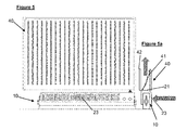
- FIG. 5 this shows the unit 10 mounted in position under a radiator, in this case a double panel radiator 40.
- the unit 10 draws in air through the front grille 23 and expels it through the top grille 21, thus driving the air between the first and second panels 41, 42 of the radiator 40.
- the modular fan unit of the present invention has been found to be capable of heating a 15m 3 room from 18°C to 21°C in 9.5 minutes. This compares to a conventional radiator, which was found to take 32 minutes.
Abstract
Description
- This invention relates, in a first aspect thereof, to a modular fan unit adapted for mounting under a conventional radiator, in order to boost natural convection. In a second aspect, the invention also relates to a modified radiator having such a modular fan unit mounted thereunder. In a third aspect, the invention further relates to a method of modifying a conventional radiator by mounting such a modular fan unit thereunder.
- Known fan-assisted radiators consist of a heat exchanger fed by a central heating or hot water system, and an electric fan arranged to blow air over the heat exchanger. Operation of the fan is generally controlled by a built-in room temperature thermostat. Such systems are efficient at transferring heat from a building's water heating system to a room, even when the temperature of the water in the heating system is relatively low. As such, they are often referred to as low energy heating products.
- Fan-assisted radiators enable a greater heat output to be achieved from a heating system operating at a set temperature than is the case with conventional radiators, which rely on natural convection currents. Conventional radiators have however remained popular, since they are considered by many to be more aesthetically pleasing. In addition, the majority of pre-existing installed central heating systems tend to be based around conventional radiators rather than fan-assisted radiators.
- Conventional radiators suffer from the shortcoming that, because of their reliance on natural convection, they cannot efficiently transfer heat from a building's water heating system to a room when the water in the system is at a low temperature (below about 75°C). The central heating boiler must therefore be operated at a temperature higher than 75°C, which leads to increased running costs, decreased efficiency, and a greater drain on fuel resources.
- In recent years, there has been a marked shift in the behaviour of consumers, who are ever more seeking environmentally benign, low energy domestic heating products. This is desirable from the point of view of economy and energy efficiency, as well as environmental considerations. However since, as noted above, most houses have a pre-existing installed central heating system based around conventional radiators, it is often impractical to change the entire system to use low energy fan-assisted radiators.
- The present invention seeks to address the above issue by providing a modular fan unit adapted for mounting under a conventional radiator, thereby to enable boosting of natural convection. The consumer can thus obtain the benefits of a low energy system, including cost savings, increased energy efficiency and lessened environmental impact, without the upheaval or cost of a full installation. The present invention further seeks to provide such a modular fan unit which can be easily installed on a DIY basis, without the need for a plumber or electrician, or any specialist skill or knowledge.
- According to a first aspect of the present invention there is provided a modular fan unit, for mounting under a conventional radiator having one or more panels, said fan unit comprising:
- a housing, adapted to be located under said conventional radiator;
- an electric fan provided within the housing and arranged to drive air upwards over said one or more panels; and
- a low temperature cut-out (LTC) sensor having magnetic attachment means for attaching to one of the panels, and adapted to activate the fan only upon water temperature in said panel reaching a pre-determined value.
- The modular fan unit of the present invention is adapted for mounting under a conventional radiator selected from a single radiator having a first panel, a double radiator having first and second panels, and a treble radiator having first, second and third panels. Each said single, double and treble radiators may be either with or without fins. Each said panel has a front face, and a rear face, and comprises a top water header, a bottom water header and vertical water ways.
- The LTC sensor preferably comprises a thermistor.
- The fan unit preferably further comprises control means arranged to operate the fan. The control means preferably comprises a multi-speed selector switch provided on the housing and adapted to enable operation of the fan at one or more speeds, and an LTC over-ride switch provided on the housing and adapted to enable operation of the fan when water temperature in the panel is below the pre-determined value. The multi-speed selector switch may be designated as a "boost" switch, with the higher speed setting(s) being intended as the "boost" function to provide quick build-up of heat when the unit is first switched on. The multi-speed selector switch may also incorporate an "on/off" switch function to switch the unit off. The LTC over-ride switch may be designated as a "summer/winter switch", since the "summer" over-ride setting enables the fan to be operated when the central heating system is not operational, thus providing a room cooling function. A room thermostat control, arranged to activate the fan only upon room temperature falling below a pre-determined value, may also be provided.
- The LTC sensor is preferably adapted to activate the fan when water temperature in the panel is substantially 45°C or higher, and to deactivate the fan when water temperature in the panel is substantially 40°C or lower. The LTC sensor is preferably attached via said magnetic attachment means to a bottom water header or a vertical water way of one of the radiator panels, at the rear face thereof.
- The modular fan unit of the present invention is intended for retro-fitting to a conventional radiator of a pre-existing central heating installation. In order to facilitate this, the unit capable of being mounted under a single, double or treble panel radiator, either with or without internal fins.
- Where the modular fan unit is to be mounted under a single radiator having a first panel, the housing is located such that the fan is arranged to drive air between said first panel and a wall on which said radiator is installed. Where the modular fan unit is to be mounted under a double radiator having first and second panels, the housing is located such that the fan is arranged to drive air between said first and second panels. Where the modular fan unit is to be mounted under a treble radiator having first, second and third panels, the housing is located such that the fan is arranged to drive air between said first and second panels, and/or between said second and third panels.
- The fan may be adapted to operate on either a 12V or 230V electrical supply, with an appropriate transformer and/or mains plug being provided accordingly. The unit is preferably supplied with a heat resistant flex which may also comprise an in-line master switch either in addition to, or instead of, the on/off switch function on the control panel.
- The housing preferably has adjustable legs, adapted to adjust the height of the unit, thereby to facilitate mounting of said unit under radiators installed at varying heights above floor level. Each leg is preferably provided with a manually operable height adjustment screw, thereby to facilitate said height adjustment. In use, the modular fan unit is mounted under a radiator such that an air gap of at least 1.5mm, and preferably substantially 1.5mm, is provided between said modular fan unit and said radiator.
- According to a second aspect of the present invention there is provided a modified radiator, having a modular fan unit as hereinbefore described mounted thereunder, thereby to modify said radiator so as to enable boosting of natural convection.
- According to a third aspect of the present invention there is provided a method of modifying a conventional radiator so as to enable boosting of natural convection, said method comprising mounting a modular fan unit as hereinbefore described under said radiator.
- The present invention thus provides a simple "retro-fit" modular fan unit for modifying a conventional radiator so as to boost natural convection. This enables energy saving by running at a lower water temperature than that of a standard radiator. The unit is provided as a "plug and play" system, which can be fitted in place under the conventional radiator, without the need for a plumber or an electrician to carry out the installation, and without the need for any specialist DIY skill, knowledge or experience. The modular unit will be supplied sealed closed, with no serviceable part. The modular unit will be sized for mounting under standard 0.6m (2ft) or 1.2m (4ft) sizes of radiator, but can be doubled up for longer panel radiators, if required. Once the modular unit is installed under a radiator, the thus modified radiator will have an appearance largely indistinguishable from that of a conventional radiator, thus minimising the aesthetic impact of installation of the modular unit.
- In order that the present invention may be more clearly understood, preferred embodiments thereof will now be described in detail, though only by way of example, with reference to the accompanying drawings, in which:
-
Figure 1 is a front view of a modular fan unit according to the present invention; -
Figure 2 is a front view of a typical panel of a conventional radiator under which the modular fan unit ofFigure 1 is to be installed; -
Figure 2a is an enlarged detail of the radiator panel ofFigure 2 ; -
Figure 2b is a side view of the radiator panel ofFigure 2 ; -
Figure 3 is an enlarged detail side view showing the modular fan unit ofFigure 1 mounted under a conventional radiator; -
Figures 4a to 4f are side views showing the modular fan unit ofFigure 1 mounted under a series of conventional radiators of differing configurations; -
Figure 5 is a front view showing the modular fan unit ofFigure 1 mounted under a conventional radiator; and -
Figure 5a is a detail side view of the radiator and fan unit arrangement ofFigure 5 . - Referring first to
Figure 1 , there is shown a modular fan unit, generally indicated 10, according to the present invention. Theunit 10 comprises aplastic housing 11 having an electric fan (not visible) housed therein, and arranged to drive air in through afront grille 23 and out through atop grille 21 provided in the upper surface of thehousing 11. A low temperature cut-out (LTC)thermistor sensor 12 is provided externally of thehousing 11, and communicates via awire 22 with control means adapted to control the operation of the fan. TheLTC thermistor sensor 12 is provided with magnetic attachment means 19 to enable thesensor 12 to be attached to aradiator panel 20. - The control means comprise a multi-speed selector "boost"
switch 13 and an LTC over-ride "summer/winter"switch 14. Theboost switch 13 also incorporates an on/off function. A standard 3-pin plug 15 is connected to theunit 10 via a 3-metre heatresistant flex 16. - The
housing 11 is provided withadjustable legs 17 at either end thereof. Eachleg 17 has a manually operableheight adjustment screw 18 to enable the height of theunit 10 to be varied according to the height of radiator under which theunit 10 is to be mounted. - Referring now to
Figure 2 , there is shown atypical panel 20 of a conventional radiator, under which themodular fan unit 10 is to be mounted. Thepanel 20 has afront face 31, arear face 32, atop water header 33, abottom water header 34 and a plurality ofvertical water ways 35. As is shown inFigures 2a and 2b , thepreferred attachment locations 36 for the magnetic attachment means 19 of theLTC sensor 12 are on therear face 32 of thepanel 20, on thebottom water header 34 or avertical water way 35. - Referring now to
Figure 3 , there is shown themodular fan unit 10 mounted under a conventionaldouble panel radiator 40, having afirst panel 41 and asecond panel 42. As can be seen, theLTC sensor 12 is attached, via the magnetic attachment means 19, to therear face 32 of thefirst panel 41. Theunit 10 is placed under theradiator 40 with itslegs 17 on thefloor 43 of the room in which the radiator is installed, with anair gap 44 between thetop grille 21 of theunit 10, and the bottom of theradiator 40. Using the manually operable height adjustment screws 18, the height of theunit 10 can then be varied, as indicated by arrows a until theair gap 44 is substantially 1.5mm, as indicated by arrows b. Theunit 10 is positioned such that air expelled from thetop grille 21 is driven between the first and second panels, 41, 42. - Referring now to
Figures 4a to 4f , there is shown themodular fan unit 10 mounted under a series of conventional radiators of differing configurations, in order to illustrate the preferred location of theLTC sensor 12, and the preferred mounting position of theunit 10, for each configuration of radiator. -
Figure 4a shows themodular fan unit 10 mounted under asingle panel radiator 30 having afirst panel 41. TheLTC sensor 12 is attached to therear face 32 of thefirst panel 41, on thebottom water header 34. Theunit 10 is positioned such that air expelled from thetop grille 21 is driven between thefirst panel 41 and thewall 37 on which theradiator 30 is installed. -
Figure 4b shows themodular fan unit 10 mounted under adouble panel radiator 40 having afirst panel 41 and asecond panel 42. Here, theLTC sensor 12 is attached to therear face 32 of thefirst panel 41, on avertical water way 35. Theunit 10 is positioned such that air expelled from thetop grille 21 is driven between thefirst panel 41 and thesecond panel 42. -
Figure 4c shows themodular fan unit 10 mounted under atreble panel radiator 50 having afirst panel 41, asecond panel 42, and athird panel 51. Here, theLTC sensor 12 is attached to therear face 32 of thesecond panel 42, on avertical water way 35. Theunit 10 is positioned such that air expelled from thetop grille 21 is driven between thesecond panel 42 and thethird panel 51. -
Figure 4d shows themodular fan unit 10 mounted under a singlepanel convector radiator 60 having afirst panel 41 provided withfins 61. TheLTC sensor 12 is attached to therear face 32 of thefirst panel 41, on thebottom water header 34. Theunit 10 is positioned such that air expelled from thetop grille 21 is driven between thefirst panel 41 and thewall 37. -
Figure 4e shows themodular fan unit 10 mounted under a doublepanel convector radiator 70 having afirst panel 41 and asecond panel 42, each provided withfins 61. TheLTC sensor 12 is again attached to therear face 32 of thefirst panel 41, on thebottom water header 34. Theunit 10 is positioned such that air expelled from thetop grille 21 is driven between thefirst panel 41 and thesecond panel 42. -
Figure 4f shows themodular fan unit 10 mounted under a treblepanel convector radiator 80 having afirst panel 41, asecond panel 42, and athird panel 51, each provided withfins 61. TheLTC sensor 12 is attached to therear face 32 of thesecond panel 42, again on thebottom water header 34. Theunit 10 is positioned such that air expelled from thetop grille 21 is driven between thesecond panel 42 and thethird panel 51. - Finally, referring to
Figure 5 , this shows theunit 10 mounted in position under a radiator, in this case adouble panel radiator 40. As illustrated inFigure 5a , theunit 10 draws in air through thefront grille 23 and expels it through thetop grille 21, thus driving the air between the first andsecond panels radiator 40. - In tests, the modular fan unit of the present invention has been found to be capable of heating a 15m3 room from 18°C to 21°C in 9.5 minutes. This compares to a conventional radiator, which was found to take 32 minutes.
Claims (15)
- A modular fan unit, for mounting under a conventional radiator having one or more panels, said fan unit comprising:- a housing, adapted to be located under said conventional radiator;- an electric fan provided within the housing and arranged to drive air upwards over said one or more panels; and- a low temperature cut-out (LTC) sensor having magnetic attachment means for attaching to one of the panels, and adapted to activate the fan only upon water temperature in said panel reaching a pre-determined value.
- A modular fan unit as claimed in claim 1, wherein the LTC sensor comprises a thermistor.
- A modular fan unit as claimed in claim 1 or claim 2, further comprising control means arranged to operate the fan, said control means comprising one or more of:- a multi-speed selector switch provided on the housing and adapted to enable operation of the fan at one or more speeds;- an LTC over-ride switch provided on the housing and adapted to enable operation of the fan when water temperature in said panel is below said pre-determined value; and- a room thermostat control arranged to activate the fan only upon room temperature falling below a pre-determined value.
- A modular fan unit as claimed in any of the preceding claims, adapted to be mounted under a single radiator having a first panel, such that the fan is arranged to drive air between said first panel and a wall on which said radiator is installed.
- A modular fan unit as claimed in any of claims 1 to 3, adapted to be mounted under a double radiator having first and second panels, such that the fan is arranged to drive air between said first and second panels.
- A modular fan unit as claimed in any of claims 1 to 3, adapted to be mounted under a treble radiator having first, second and third panels, such that the fan is arranged to drive air between said first and second panels, and/or between said second and third panels.
- A modular fan unit as claimed in any of the preceding claims, wherein the fan is adapted to operate on a 12V electrical supply or a 230V electrical supply.
- A modular fan unit as claimed in any of the preceding claims, wherein the LTC sensor is adapted to activate the fan when water temperature in the panel is substantially 45°C or higher.
- A modular fan unit as claimed in claim 9, wherein the LTC sensor is adapted to deactivate the fan when water temperature in the panel is substantially 40°C or lower.
- A modular fan unit as claimed in any of the preceding claims, wherein the housing has adjustable legs adapted to adjust the height of the unit, thereby to facilitate mounting of said unit under radiators installed at varying heights above floor level, and wherein each leg is provided with a manually operable height adjustment screw, thereby to facilitate said height adjustment.
- A modular fan unit as claimed in any of the preceding claims, wherein said housing is formed from plastics material and remains at ambient temperature during operation of the unit.
- A modified radiator having one or more panels each having a front face and a rear face, and wherein a modular fan unit as claimed in any of the preceding claims is mounted thereunder, thereby to modify said radiator so as to enable boosting of natural convection.
- A modified radiator as claimed in claim 12, wherein the modular fan unit is mounted thereunder such that an air gap of at least 1.5mm is provided between said modular fan unit and said radiator.
- A modified radiator as claimed in claim 12 or claim 13, wherein said one or more panels each has a top water header, a bottom water header and vertical water ways, and wherein said LTC sensor is attached via said magnetic attachment means to a bottom water header or a vertical water way of one of said panels, at the rear face thereof.
- A method of modifying a conventional radiator so as to enable boosting of natural convection, said method comprising mounting a modular fan unit as claimed in any of claims 1 to 11 under said radiator, thereby to provide a modified radiator as claimed in any of claims 12 to 14.
Applications Claiming Priority (1)
| Application Number | Priority Date | Filing Date | Title |
|---|---|---|---|
| GB1513275.6A GB2540794B (en) | 2015-07-28 | 2015-07-28 | Radiator fan unit |
Publications (2)
| Publication Number | Publication Date |
|---|---|
| EP3124879A1 true EP3124879A1 (en) | 2017-02-01 |
| EP3124879B1 EP3124879B1 (en) | 2020-06-10 |
Family
ID=54106729
Family Applications (1)
| Application Number | Title | Priority Date | Filing Date |
|---|---|---|---|
| EP16181471.0A Active EP3124879B1 (en) | 2015-07-28 | 2016-07-27 | Radiator fan unit |
Country Status (2)
| Country | Link |
|---|---|
| EP (1) | EP3124879B1 (en) |
| GB (1) | GB2540794B (en) |
Cited By (1)
| Publication number | Priority date | Publication date | Assignee | Title |
|---|---|---|---|---|
| EP3499136A1 (en) | 2017-12-15 | 2019-06-19 | Francesco Jacobino | Modular device for radiators |
Citations (5)
| Publication number | Priority date | Publication date | Assignee | Title |
|---|---|---|---|---|
| US3324938A (en) * | 1965-10-04 | 1967-06-13 | Martin G Berkoff | Convection heat booster |
| US4126268A (en) * | 1977-02-18 | 1978-11-21 | Vitale John E | Portable room-temperature controller |
| ES2073340A2 (en) * | 1993-02-19 | 1995-08-01 | Avila Jesus Quintanilla | Thermostatted convector of air forced via power fans for domestic (household) heating radiators |
| GB2337811A (en) * | 1998-05-28 | 1999-12-01 | Alan James Shone | Portable radiator enhancer |
| GB2492346A (en) * | 2011-06-28 | 2013-01-02 | Smiths Environmental Products Ltd | Heating unit having powered convection |
Family Cites Families (5)
| Publication number | Priority date | Publication date | Assignee | Title |
|---|---|---|---|---|
| GB2424062A (en) * | 2005-03-08 | 2006-09-13 | Abu Batin Syed | A solar powered heat circulating booster used with a domestic radiator |
| DE202010011282U1 (en) * | 2010-08-11 | 2010-10-28 | Michalzik, Claudia | Accessory for radiators |
| GB201111341D0 (en) * | 2011-07-04 | 2011-08-17 | Glancy Roland J T | Warm air circulating device |
| DE102011109168B3 (en) * | 2011-08-02 | 2012-09-06 | Harald Heim | Fan unit for radiator of heat pump, has fastening unit for fixing on radiator that is connected in main casing through vibration-resistant connecting elements which are elastic |
| GB2522423B (en) * | 2014-01-22 | 2017-07-12 | Stanton Webster Gary | Radiator fan unit |
-
2015
- 2015-07-28 GB GB1513275.6A patent/GB2540794B/en not_active Expired - Fee Related
-
2016
- 2016-07-27 EP EP16181471.0A patent/EP3124879B1/en active Active
Patent Citations (5)
| Publication number | Priority date | Publication date | Assignee | Title |
|---|---|---|---|---|
| US3324938A (en) * | 1965-10-04 | 1967-06-13 | Martin G Berkoff | Convection heat booster |
| US4126268A (en) * | 1977-02-18 | 1978-11-21 | Vitale John E | Portable room-temperature controller |
| ES2073340A2 (en) * | 1993-02-19 | 1995-08-01 | Avila Jesus Quintanilla | Thermostatted convector of air forced via power fans for domestic (household) heating radiators |
| GB2337811A (en) * | 1998-05-28 | 1999-12-01 | Alan James Shone | Portable radiator enhancer |
| GB2492346A (en) * | 2011-06-28 | 2013-01-02 | Smiths Environmental Products Ltd | Heating unit having powered convection |
Cited By (1)
| Publication number | Priority date | Publication date | Assignee | Title |
|---|---|---|---|---|
| EP3499136A1 (en) | 2017-12-15 | 2019-06-19 | Francesco Jacobino | Modular device for radiators |
Also Published As
| Publication number | Publication date |
|---|---|
| EP3124879B1 (en) | 2020-06-10 |
| GB201513275D0 (en) | 2015-09-09 |
| GB2540794B (en) | 2020-02-26 |
| GB2540794A (en) | 2017-02-01 |
Similar Documents
| Publication | Publication Date | Title |
|---|---|---|
| CN203731538U (en) | High-efficiency energy-saving electric heater | |
| CN105222259A (en) | A kind of Integral ceiling ventilation wind warms up lighting all-in-one machine | |
| EP3124879B1 (en) | Radiator fan unit | |
| CN203985427U (en) | A kind of pet cage with thermoregulator | |
| US20100206541A1 (en) | Fan convector heating unit | |
| GB2411463A (en) | Portable fan unit mounted on top of a central heating radiator | |
| CN206905086U (en) | A kind of heat-storage electric heater | |
| GB2522423A (en) | Radiator fan unit | |
| CN206469335U (en) | Horizontal cross convection type is cold, warm up dual-purpose electric heating installation using oil as medium | |
| CN106642288A (en) | Horizontal transverse convection type cold and warm dual-purpose electrical oil heater | |
| GB2456392A (en) | Panel heating device | |
| GB2130705A (en) | Heating systems | |
| GB2337811A (en) | Portable radiator enhancer | |
| CN103398413B (en) | Intelligent electromagnetic adds heating water device for warming | |
| CN202371528U (en) | Floor lamp | |
| WO2017158580A1 (en) | A space temperature controlling apparatus and a space heating apparatus | |
| CN210179899U (en) | Convection type PTC warming machine | |
| WO2009014478A1 (en) | Flexible mounting and installation system with components specially adapted for the transport of air | |
| CN201757457U (en) | Indoor electric heater | |
| CN206669855U (en) | A kind of indoor heater | |
| EP2499433A2 (en) | Energy efficient heating installation | |
| CN211316315U (en) | Electromagnetic air heater | |
| CN2669038Y (en) | Water-heating warming device for dweling rooms | |
| CN203928108U (en) | A kind of low-power electric heating is without spit of fland horizontal type heat abstractor | |
| CN215723494U (en) | Intelligent warmer |
Legal Events
| Date | Code | Title | Description |
|---|---|---|---|
| PUAI | Public reference made under article 153(3) epc to a published international application that has entered the european phase |
Free format text: ORIGINAL CODE: 0009012 |
|
| STAA | Information on the status of an ep patent application or granted ep patent |
Free format text: STATUS: THE APPLICATION HAS BEEN PUBLISHED |
|
| AK | Designated contracting states |
Kind code of ref document: A1 Designated state(s): AL AT BE BG CH CY CZ DE DK EE ES FI FR GB GR HR HU IE IS IT LI LT LU LV MC MK MT NL NO PL PT RO RS SE SI SK SM TR |
|
| AX | Request for extension of the european patent |
Extension state: BA ME |
|
| STAA | Information on the status of an ep patent application or granted ep patent |
Free format text: STATUS: REQUEST FOR EXAMINATION WAS MADE |
|
| 17P | Request for examination filed |
Effective date: 20170801 |
|
| RBV | Designated contracting states (corrected) |
Designated state(s): AL AT BE BG CH CY CZ DE DK EE ES FI FR GB GR HR HU IE IS IT LI LT LU LV MC MK MT NL NO PL PT RO RS SE SI SK SM TR |
|
| STAA | Information on the status of an ep patent application or granted ep patent |
Free format text: STATUS: EXAMINATION IS IN PROGRESS |
|
| 17Q | First examination report despatched |
Effective date: 20190225 |
|
| GRAP | Despatch of communication of intention to grant a patent |
Free format text: ORIGINAL CODE: EPIDOSNIGR1 |
|
| STAA | Information on the status of an ep patent application or granted ep patent |
Free format text: STATUS: GRANT OF PATENT IS INTENDED |
|
| INTG | Intention to grant announced |
Effective date: 20191217 |
|
| GRAS | Grant fee paid |
Free format text: ORIGINAL CODE: EPIDOSNIGR3 |
|
| GRAA | (expected) grant |
Free format text: ORIGINAL CODE: 0009210 |
|
| STAA | Information on the status of an ep patent application or granted ep patent |
Free format text: STATUS: THE PATENT HAS BEEN GRANTED |
|
| AK | Designated contracting states |
Kind code of ref document: B1 Designated state(s): AL AT BE BG CH CY CZ DE DK EE ES FI FR GB GR HR HU IE IS IT LI LT LU LV MC MK MT NL NO PL PT RO RS SE SI SK SM TR |
|
| REG | Reference to a national code |
Ref country code: GB Ref legal event code: FG4D |
|
| REG | Reference to a national code |
Ref country code: CH Ref legal event code: EP Ref country code: AT Ref legal event code: REF Ref document number: 1279503 Country of ref document: AT Kind code of ref document: T Effective date: 20200615 |
|
| REG | Reference to a national code |
Ref country code: DE Ref legal event code: R096 Ref document number: 602016037802 Country of ref document: DE |
|
| REG | Reference to a national code |
Ref country code: IE Ref legal event code: FG4D |
|
| REG | Reference to a national code |
Ref country code: LT Ref legal event code: MG4D |
|
| PG25 | Lapsed in a contracting state [announced via postgrant information from national office to epo] |
Ref country code: GR Free format text: LAPSE BECAUSE OF FAILURE TO SUBMIT A TRANSLATION OF THE DESCRIPTION OR TO PAY THE FEE WITHIN THE PRESCRIBED TIME-LIMIT Effective date: 20200911 Ref country code: NO Free format text: LAPSE BECAUSE OF FAILURE TO SUBMIT A TRANSLATION OF THE DESCRIPTION OR TO PAY THE FEE WITHIN THE PRESCRIBED TIME-LIMIT Effective date: 20200910 Ref country code: FI Free format text: LAPSE BECAUSE OF FAILURE TO SUBMIT A TRANSLATION OF THE DESCRIPTION OR TO PAY THE FEE WITHIN THE PRESCRIBED TIME-LIMIT Effective date: 20200610 Ref country code: SE Free format text: LAPSE BECAUSE OF FAILURE TO SUBMIT A TRANSLATION OF THE DESCRIPTION OR TO PAY THE FEE WITHIN THE PRESCRIBED TIME-LIMIT Effective date: 20200610 Ref country code: LT Free format text: LAPSE BECAUSE OF FAILURE TO SUBMIT A TRANSLATION OF THE DESCRIPTION OR TO PAY THE FEE WITHIN THE PRESCRIBED TIME-LIMIT Effective date: 20200610 |
|
| REG | Reference to a national code |
Ref country code: NL Ref legal event code: MP Effective date: 20200610 |
|
| PG25 | Lapsed in a contracting state [announced via postgrant information from national office to epo] |
Ref country code: RS Free format text: LAPSE BECAUSE OF FAILURE TO SUBMIT A TRANSLATION OF THE DESCRIPTION OR TO PAY THE FEE WITHIN THE PRESCRIBED TIME-LIMIT Effective date: 20200610 Ref country code: BG Free format text: LAPSE BECAUSE OF FAILURE TO SUBMIT A TRANSLATION OF THE DESCRIPTION OR TO PAY THE FEE WITHIN THE PRESCRIBED TIME-LIMIT Effective date: 20200910 Ref country code: LV Free format text: LAPSE BECAUSE OF FAILURE TO SUBMIT A TRANSLATION OF THE DESCRIPTION OR TO PAY THE FEE WITHIN THE PRESCRIBED TIME-LIMIT Effective date: 20200610 Ref country code: HR Free format text: LAPSE BECAUSE OF FAILURE TO SUBMIT A TRANSLATION OF THE DESCRIPTION OR TO PAY THE FEE WITHIN THE PRESCRIBED TIME-LIMIT Effective date: 20200610 |
|
| REG | Reference to a national code |
Ref country code: AT Ref legal event code: MK05 Ref document number: 1279503 Country of ref document: AT Kind code of ref document: T Effective date: 20200610 |
|
| PG25 | Lapsed in a contracting state [announced via postgrant information from national office to epo] |
Ref country code: AL Free format text: LAPSE BECAUSE OF FAILURE TO SUBMIT A TRANSLATION OF THE DESCRIPTION OR TO PAY THE FEE WITHIN THE PRESCRIBED TIME-LIMIT Effective date: 20200610 Ref country code: NL Free format text: LAPSE BECAUSE OF FAILURE TO SUBMIT A TRANSLATION OF THE DESCRIPTION OR TO PAY THE FEE WITHIN THE PRESCRIBED TIME-LIMIT Effective date: 20200610 |
|
| PG25 | Lapsed in a contracting state [announced via postgrant information from national office to epo] |
Ref country code: AT Free format text: LAPSE BECAUSE OF FAILURE TO SUBMIT A TRANSLATION OF THE DESCRIPTION OR TO PAY THE FEE WITHIN THE PRESCRIBED TIME-LIMIT Effective date: 20200610 Ref country code: ES Free format text: LAPSE BECAUSE OF FAILURE TO SUBMIT A TRANSLATION OF THE DESCRIPTION OR TO PAY THE FEE WITHIN THE PRESCRIBED TIME-LIMIT Effective date: 20200610 Ref country code: SM Free format text: LAPSE BECAUSE OF FAILURE TO SUBMIT A TRANSLATION OF THE DESCRIPTION OR TO PAY THE FEE WITHIN THE PRESCRIBED TIME-LIMIT Effective date: 20200610 Ref country code: EE Free format text: LAPSE BECAUSE OF FAILURE TO SUBMIT A TRANSLATION OF THE DESCRIPTION OR TO PAY THE FEE WITHIN THE PRESCRIBED TIME-LIMIT Effective date: 20200610 Ref country code: IT Free format text: LAPSE BECAUSE OF FAILURE TO SUBMIT A TRANSLATION OF THE DESCRIPTION OR TO PAY THE FEE WITHIN THE PRESCRIBED TIME-LIMIT Effective date: 20200610 Ref country code: RO Free format text: LAPSE BECAUSE OF FAILURE TO SUBMIT A TRANSLATION OF THE DESCRIPTION OR TO PAY THE FEE WITHIN THE PRESCRIBED TIME-LIMIT Effective date: 20200610 Ref country code: CZ Free format text: LAPSE BECAUSE OF FAILURE TO SUBMIT A TRANSLATION OF THE DESCRIPTION OR TO PAY THE FEE WITHIN THE PRESCRIBED TIME-LIMIT Effective date: 20200610 Ref country code: PT Free format text: LAPSE BECAUSE OF FAILURE TO SUBMIT A TRANSLATION OF THE DESCRIPTION OR TO PAY THE FEE WITHIN THE PRESCRIBED TIME-LIMIT Effective date: 20201012 |
|
| REG | Reference to a national code |
Ref country code: DE Ref legal event code: R119 Ref document number: 602016037802 Country of ref document: DE |
|
| PG25 | Lapsed in a contracting state [announced via postgrant information from national office to epo] |
Ref country code: PL Free format text: LAPSE BECAUSE OF FAILURE TO SUBMIT A TRANSLATION OF THE DESCRIPTION OR TO PAY THE FEE WITHIN THE PRESCRIBED TIME-LIMIT Effective date: 20200610 Ref country code: SK Free format text: LAPSE BECAUSE OF FAILURE TO SUBMIT A TRANSLATION OF THE DESCRIPTION OR TO PAY THE FEE WITHIN THE PRESCRIBED TIME-LIMIT Effective date: 20200610 Ref country code: IS Free format text: LAPSE BECAUSE OF FAILURE TO SUBMIT A TRANSLATION OF THE DESCRIPTION OR TO PAY THE FEE WITHIN THE PRESCRIBED TIME-LIMIT Effective date: 20201010 |
|
| REG | Reference to a national code |
Ref country code: CH Ref legal event code: PL |
|
| PG25 | Lapsed in a contracting state [announced via postgrant information from national office to epo] |
Ref country code: MC Free format text: LAPSE BECAUSE OF FAILURE TO SUBMIT A TRANSLATION OF THE DESCRIPTION OR TO PAY THE FEE WITHIN THE PRESCRIBED TIME-LIMIT Effective date: 20200610 |
|
| PLBE | No opposition filed within time limit |
Free format text: ORIGINAL CODE: 0009261 |
|
| STAA | Information on the status of an ep patent application or granted ep patent |
Free format text: STATUS: NO OPPOSITION FILED WITHIN TIME LIMIT |
|
| REG | Reference to a national code |
Ref country code: BE Ref legal event code: MM Effective date: 20200731 |
|
| PG25 | Lapsed in a contracting state [announced via postgrant information from national office to epo] |
Ref country code: CH Free format text: LAPSE BECAUSE OF NON-PAYMENT OF DUE FEES Effective date: 20200731 Ref country code: DK Free format text: LAPSE BECAUSE OF FAILURE TO SUBMIT A TRANSLATION OF THE DESCRIPTION OR TO PAY THE FEE WITHIN THE PRESCRIBED TIME-LIMIT Effective date: 20200610 Ref country code: LU Free format text: LAPSE BECAUSE OF NON-PAYMENT OF DUE FEES Effective date: 20200727 Ref country code: LI Free format text: LAPSE BECAUSE OF NON-PAYMENT OF DUE FEES Effective date: 20200731 |
|
| 26N | No opposition filed |
Effective date: 20210311 |
|
| GBPC | Gb: european patent ceased through non-payment of renewal fee |
Effective date: 20200910 |
|
| PG25 | Lapsed in a contracting state [announced via postgrant information from national office to epo] |
Ref country code: DE Free format text: LAPSE BECAUSE OF NON-PAYMENT OF DUE FEES Effective date: 20210202 Ref country code: BE Free format text: LAPSE BECAUSE OF NON-PAYMENT OF DUE FEES Effective date: 20200731 Ref country code: SI Free format text: LAPSE BECAUSE OF FAILURE TO SUBMIT A TRANSLATION OF THE DESCRIPTION OR TO PAY THE FEE WITHIN THE PRESCRIBED TIME-LIMIT Effective date: 20200610 |
|
| PG25 | Lapsed in a contracting state [announced via postgrant information from national office to epo] |
Ref country code: FR Free format text: LAPSE BECAUSE OF NON-PAYMENT OF DUE FEES Effective date: 20200810 |
|
| PG25 | Lapsed in a contracting state [announced via postgrant information from national office to epo] |
Ref country code: GB Free format text: LAPSE BECAUSE OF NON-PAYMENT OF DUE FEES Effective date: 20200910 Ref country code: IE Free format text: LAPSE BECAUSE OF NON-PAYMENT OF DUE FEES Effective date: 20200727 |
|
| PG25 | Lapsed in a contracting state [announced via postgrant information from national office to epo] |
Ref country code: TR Free format text: LAPSE BECAUSE OF FAILURE TO SUBMIT A TRANSLATION OF THE DESCRIPTION OR TO PAY THE FEE WITHIN THE PRESCRIBED TIME-LIMIT Effective date: 20200610 Ref country code: MT Free format text: LAPSE BECAUSE OF FAILURE TO SUBMIT A TRANSLATION OF THE DESCRIPTION OR TO PAY THE FEE WITHIN THE PRESCRIBED TIME-LIMIT Effective date: 20200610 Ref country code: CY Free format text: LAPSE BECAUSE OF FAILURE TO SUBMIT A TRANSLATION OF THE DESCRIPTION OR TO PAY THE FEE WITHIN THE PRESCRIBED TIME-LIMIT Effective date: 20200610 |
|
| PG25 | Lapsed in a contracting state [announced via postgrant information from national office to epo] |
Ref country code: MK Free format text: LAPSE BECAUSE OF FAILURE TO SUBMIT A TRANSLATION OF THE DESCRIPTION OR TO PAY THE FEE WITHIN THE PRESCRIBED TIME-LIMIT Effective date: 20200610 |