EP3136113A1 - Optical acceleration sensor - Google Patents
Optical acceleration sensor Download PDFInfo
- Publication number
- EP3136113A1 EP3136113A1 EP16185686.9A EP16185686A EP3136113A1 EP 3136113 A1 EP3136113 A1 EP 3136113A1 EP 16185686 A EP16185686 A EP 16185686A EP 3136113 A1 EP3136113 A1 EP 3136113A1
- Authority
- EP
- European Patent Office
- Prior art keywords
- acceleration sensor
- seismic mass
- optical
- light beam
- sensor according
- Prior art date
- Legal status (The legal status is an assumption and is not a legal conclusion. Google has not performed a legal analysis and makes no representation as to the accuracy of the status listed.)
- Withdrawn
Links
Images


Classifications
-
- G—PHYSICS
- G01—MEASURING; TESTING
- G01P—MEASURING LINEAR OR ANGULAR SPEED, ACCELERATION, DECELERATION, OR SHOCK; INDICATING PRESENCE, ABSENCE, OR DIRECTION, OF MOVEMENT
- G01P15/00—Measuring acceleration; Measuring deceleration; Measuring shock, i.e. sudden change of acceleration
- G01P15/02—Measuring acceleration; Measuring deceleration; Measuring shock, i.e. sudden change of acceleration by making use of inertia forces using solid seismic masses
- G01P15/08—Measuring acceleration; Measuring deceleration; Measuring shock, i.e. sudden change of acceleration by making use of inertia forces using solid seismic masses with conversion into electric or magnetic values
- G01P15/093—Measuring acceleration; Measuring deceleration; Measuring shock, i.e. sudden change of acceleration by making use of inertia forces using solid seismic masses with conversion into electric or magnetic values by photoelectric pick-up
-
- G—PHYSICS
- G01—MEASURING; TESTING
- G01N—INVESTIGATING OR ANALYSING MATERIALS BY DETERMINING THEIR CHEMICAL OR PHYSICAL PROPERTIES
- G01N21/00—Investigating or analysing materials by the use of optical means, i.e. using sub-millimetre waves, infrared, visible or ultraviolet light
- G01N21/17—Systems in which incident light is modified in accordance with the properties of the material investigated
- G01N21/47—Scattering, i.e. diffuse reflection
- G01N21/4738—Diffuse reflection, e.g. also for testing fluids, fibrous materials
- G01N21/474—Details of optical heads therefor, e.g. using optical fibres
-
- G—PHYSICS
- G01—MEASURING; TESTING
- G01P—MEASURING LINEAR OR ANGULAR SPEED, ACCELERATION, DECELERATION, OR SHOCK; INDICATING PRESENCE, ABSENCE, OR DIRECTION, OF MOVEMENT
- G01P1/00—Details of instruments
- G01P1/02—Housings
- G01P1/023—Housings for acceleration measuring devices
-
- G—PHYSICS
- G01—MEASURING; TESTING
- G01N—INVESTIGATING OR ANALYSING MATERIALS BY DETERMINING THEIR CHEMICAL OR PHYSICAL PROPERTIES
- G01N21/00—Investigating or analysing materials by the use of optical means, i.e. using sub-millimetre waves, infrared, visible or ultraviolet light
- G01N21/17—Systems in which incident light is modified in accordance with the properties of the material investigated
- G01N21/47—Scattering, i.e. diffuse reflection
- G01N21/4738—Diffuse reflection, e.g. also for testing fluids, fibrous materials
- G01N21/474—Details of optical heads therefor, e.g. using optical fibres
- G01N2021/4742—Details of optical heads therefor, e.g. using optical fibres comprising optical fibres
-
- G—PHYSICS
- G01—MEASURING; TESTING
- G01P—MEASURING LINEAR OR ANGULAR SPEED, ACCELERATION, DECELERATION, OR SHOCK; INDICATING PRESENCE, ABSENCE, OR DIRECTION, OF MOVEMENT
- G01P15/00—Measuring acceleration; Measuring deceleration; Measuring shock, i.e. sudden change of acceleration
- G01P15/02—Measuring acceleration; Measuring deceleration; Measuring shock, i.e. sudden change of acceleration by making use of inertia forces using solid seismic masses
- G01P15/08—Measuring acceleration; Measuring deceleration; Measuring shock, i.e. sudden change of acceleration by making use of inertia forces using solid seismic masses with conversion into electric or magnetic values
- G01P2015/0805—Measuring acceleration; Measuring deceleration; Measuring shock, i.e. sudden change of acceleration by making use of inertia forces using solid seismic masses with conversion into electric or magnetic values being provided with a particular type of spring-mass-system for defining the displacement of a seismic mass due to an external acceleration
- G01P2015/0822—Measuring acceleration; Measuring deceleration; Measuring shock, i.e. sudden change of acceleration by making use of inertia forces using solid seismic masses with conversion into electric or magnetic values being provided with a particular type of spring-mass-system for defining the displacement of a seismic mass due to an external acceleration for defining out-of-plane movement of the mass
- G01P2015/0825—Measuring acceleration; Measuring deceleration; Measuring shock, i.e. sudden change of acceleration by making use of inertia forces using solid seismic masses with conversion into electric or magnetic values being provided with a particular type of spring-mass-system for defining the displacement of a seismic mass due to an external acceleration for defining out-of-plane movement of the mass for one single degree of freedom of movement of the mass
- G01P2015/0828—Measuring acceleration; Measuring deceleration; Measuring shock, i.e. sudden change of acceleration by making use of inertia forces using solid seismic masses with conversion into electric or magnetic values being provided with a particular type of spring-mass-system for defining the displacement of a seismic mass due to an external acceleration for defining out-of-plane movement of the mass for one single degree of freedom of movement of the mass the mass being of the paddle type being suspended at one of its longitudinal ends
Abstract
L'invention concerne un capteur d'accélération de type optique comportant une masse sismique (12), pourvue d'une surface réfléchissante (16) mobile selon un axe de rotation, une fibre optique émettrice (10) couplée à une source de lumière (11), destinée à émettre un faisceau lumineux (L), par une de ses extrémités (8), en direction de la surface réfléchissante (16), et une fibre optique réceptrice (20) couplée à un détecteur optique (21), destinée à recevoir, par une de ses extrémités (9), le faisceau lumineux (L) renvoyé par la surface réfléchissante (16). Un mouvement de rotation de la surface réfléchissante (16) entraîne une déflexion du faisceau lumineux (L) et une variation de l'intensité lumineuse reçue par la fibre réceptrice (20). Une lentille convergente (30) est interposée, sur le trajet optique du faisceau lumineux, entre les fibres optiques (10, 20) et la masse sismique (12).

Description
La présente invention se rapporte au domaine des accéléromètres. Elle concerne plus particulièrement un capteur d'accélération de type optique, couplant une masse sismique à au moins une fibre optique.The present invention relates to the field of accelerometers. It relates more particularly to an optical type acceleration sensor, coupling a seismic mass to at least one optical fiber.
De tels accéléromètres sont connus de l'homme de métier et fonctionnent selon un principe générique simple : Une masse sismique coopère avec une fibre optique émettant un faisceau lumineux. Sous l'effet de l'accélération, la masse sismique se déplace, provoquant une déflexion du faisceau lumineux, laquelle fournit une indication de l'accélération. Ils sont destinés à la surveillance d'installations soumises à des environnements hostiles, tels que des générateurs éléctriques, des éoliennes, des trains, ou tout autre construction critique.Such accelerometers are known to those skilled in the art and operate according to a simple generic principle: A seismic mass cooperates with an optical fiber emitting a light beam. Under the effect of acceleration, the seismic mass moves, causing a deflection of the light beam, which provides an indication of the acceleration. They are intended for monitoring installations subject to hostile environments, such as electric generators, wind turbines, trains, or any other critical construction.
Différents dispositifs basés sur ce principe sont décrits dans l'état de la technique. Le document
Le document
Un tel dispositif, bien que fonctionnel et de conception simple, présente plusieurs inconvénients. En premier lieu, le contact entre les fibres optiques et le MEMS est problématique : Sa mise en oeuvre, par collage ou soudage, est malaisée et le mouvement de rotation de la plaque mobile s'en trouve perturbé, ce qui a un impact direct sur la justesse de la mesure. Par ailleurs, la disposition des fibres émettrice et réceptrice en regard l'une de l'autre n'est pas optimale. En effet, un tel dispositif est généralement enfermé dans un boîtier hermétique, en vue de le protéger de l'environnement extérieur. Les fibres optiques ainsi alignées émergent du boîtier par deux faces distinctes et opposées, ce qui confère au dispositif un encombrement important et complique l'intégration de l'accéléromètre au point de mesure. De plus, l'herméticité du boîtier est compromise par les fibres qui le traversent. Enfin, le déplacement du spot produit par l'impact du faisceau lumineux en entrée de la fibre réceptrice est fonction de la déflexion du faisceau lumineux, soit de la rotation α de la plaque plane. Plus précisément, le déplacement du spot est proportionnel à la tangente de l'angle α, environ égale à α pour des angles inférieurs ou égaux à 15°, et à la largeur de la masse sismique. Compte tenu des dimensions des MEMS, l'effet d'une faible accélération ne produit qu'un déplacement minime du faisceau lumineux, et, par suite, une très faible variation de l'intensité lumineuse reçue. La sensibilité de l'accéléromètre ainsi décrit est ainsi médiocre.Such a device, although functional and simple in design, has several disadvantages. Firstly, the contact between the optical fibers and the MEMS is problematic: its implementation, by gluing or welding, is difficult and the rotational movement of the movable plate is disturbed, which has a direct impact on the correctness of the measure. Moreover, the arrangement of the emitter and receiver fibers facing each other is not optimal. Indeed, such a device is usually enclosed in a hermetic housing, in order to protect it from the outside environment. The optical fibers thus aligned emerge from the housing by two distinct and opposite faces, which gives the device a large footprint and complicates the integration of the accelerometer at the measurement point. In addition, the hermeticity of the housing is compromised by the fibers that pass through it. Finally, the displacement of the spot produced by the impact of the light beam at the input of the receiving fiber is a function of the deflection of the light beam, ie of the rotation α of the plane plate. More precisely, the displacement of the spot is proportional to the tangent of the angle α, approximately equal to α for angles less than or equal to 15 °, and to the width of the seismic mass. Given the size of the MEMS, the effect of a weak acceleration produces only a minimal displacement of the light beam, and, consequently, a very small variation in the luminous intensity received. The sensitivity of the accelerometer thus described is thus poor.
La présente invention a pour but de remédier aux inconvénients précités, en proposant un accéléromètre présentant une grande sensibilité de mesure alliée à une justesse accrue. De plus, la structure de l'accéléromètre selon l'invention permet une intégration facilitée du dispositif au point où la mesure doit être effectuée, grâce à la position des fibres en sortie du boîtier. Plus précisément, l'invention concerne un capteur d'accélération de type optique comportant une masse sismique, pourvue d'une surface réfléchissante mobile selon un axe de rotation, une fibre optique émettrice couplée à une source de lumière, destinée à émettre un faisceau lumineux, par une de ses extrémités, en direction de la surface réfléchissante, et une fibre optique réceptrice couplée à un détecteur optique, destinée à recevoir, par une de ses extrémités, le faisceau lumineux renvoyé par la surface réfléchissante, un mouvement de rotation de la surface réfléchissante entraînant une déflexion du faisceau lumineux et une variation de l'intensité lumineuse reçue par la fibre réceptrice. Selon l'invention, une lentille convergente est interposée, sur le trajet optique du faisceau lumineux, entre les fibres optiques et ladite masse sismique.The present invention aims to overcome the aforementioned drawbacks, by proposing an accelerometer having a high sensitivity of measurement combined with increased accuracy. In addition, the structure of the accelerometer according to the invention allows easy integration of the device to the point where the measurement must be made, thanks to the position of the fibers at the output of the housing. More specifically, the invention relates to an optical type acceleration sensor comprising a seismic mass, provided with a reflecting surface movable along an axis of rotation, an optical fiber transmitter coupled to a light source, for emitting a light beam, at one of its ends, in the direction of the reflecting surface, and a receiving optical fiber coupled to an optical detector, for receiving, at one of its ends, the light beam reflected by the reflecting surface, a rotational movement of the reflecting surface causing a deflection of the light beam and a variation of the light intensity received by the receiving fiber. According to the invention, a converging lens is interposed, in the optical path of the light beam, between the optical fibers and the said seismic mass.
La présence d'une lentille convergente interposée entre les fibres émettrice et réceptrice de l'accéléromètre selon l'invention, introduit une distance physique entre les fibres et la masse sismique. Les effets produits sont la suppression du contact problématique entre les fibres et la masse sismique, et l'augmentation du trajet optique du faisceau lumineux entre les fibres émettrice et réceptrice. En terme de performance de l'accéléromètre, ces effets se traduisent par une amélioration de la justesse de la mesure et une sensibilité accrue. Pour un angle de déflexion α de la masse sismique donné, la géométrie du dispositif selon l'invention permet un déplacement substantiel du faisceau lumineux à l'entrée de la fibre réceptrice, et, par voie de conséquence, une sensibilité élevée à de faibles accélérations, comme il apparaîtra par la suite. Une autre conséquence de l'éloignement des fibres optiques de la masse sismique, est l'encapsulation facilitée de cette dernière dans un boîtier hermétique. Les fibres optiques étant distantes de la masse sismique, il est possible de les disposer à l'extérieur du boîtier hermétique, la lentille étant montée directement sur celui-ci. Cette structure est avantageuse car il est malaisé de monter des fibres optiques de façon hermétique à travers une séparation entre deux milieux. Enfin, on notera qu'au sein de l'accéléromètre selon l'invention, la fonction de la masse sismique est de réfléchir le faisceau lumineux émis dans une direction qui varie en fonction de l'accélération subie. Cette caractéristique autorise différentes positions relatives des axes longitudinaux des fibres optiques. En particulier, les fibres émettrices et réceptrices peuvent être parallèles et voisines l'une de l'autre, auquel cas elles et émergent du dispositif par une même face, et l'encombrement du dispositif est minimal.The presence of a convergent lens interposed between the emitter and receiver fibers of the accelerometer according to the invention introduces a physical distance between the fibers and the seismic mass. The effects produced are the removal of the problematic contact between the fibers and the seismic mass, and the increase in the optical path of the light beam between the emitter and receiver fibers. In terms of accelerometer performance, these effects translate into improved measurement accuracy and increased sensitivity. For a deflection angle α of the given seismic mass, the geometry of the device according to the invention allows a substantial displacement of the light beam at the entrance of the receiving fiber, and, consequently, a high sensitivity to low accelerations. as it will appear later. Another consequence of the distance of the optical fibers from the seismic mass, is the facilitated encapsulation of the latter in a hermetic housing. Since the optical fibers are distant from the seismic mass, it is possible to place them outside the hermetic housing, the lens being mounted directly on the latter. This structure is advantageous because it is difficult to mount optical fibers hermetically through a separation between two media. Finally, it will be noted that within the accelerometer according to the invention, the function of the seismic mass is to reflect the light beam emitted in a direction which varies as a function of the acceleration undergone. This characteristic allows different relative positions of the longitudinal axes of the optical fibers. In particular, the transmitting and receiving fibers may be parallel and close to each other, in which case they emerge from the device by the same face, and the size of the device is minimal.
D'autres caractéristiques et avantages de la présente invention apparaîtront à la lecture de la description qui suit, donnée uniquement à titre d'exemple et faite en référence aux dessins annexés dans lesquels :
- les
figures 1 à 3 sont des vues schématiques de côté de différents modes de réalisation d'un accéléromètre de type optique selon l'invention, - la
figure 4 est une vue en perspective d'une masse sismique appartenant à l'accéléromètre selon l'invention, et - la
figure 5 illustre schématiquement le principe de détermination de l'accélération à l'aide de l'accéléromètre selon l'invention.
- the
Figures 1 to 3 are schematic side views of different embodiments of an optical type accelerometer according to the invention, - the
figure 4 is a perspective view of a seismic mass belonging to the accelerometer according to the invention, and - the
figure 5 schematically illustrates the principle of determining the acceleration using the accelerometer according to the invention.
Le capteur d'accélération de type optique représenté schématiquement en
A cet effet, la masse sismique 12, illustrée en
Le capteur 1 comporte encore une fibre optique réceptrice 20, couplée à un détecteur optique 21, de type photodiode ou phototransistor. Elle est destinée à collecter, par une des ses extrémités 9, le faisceau lumineux L émis par la fibre émettrice 10 et réfléchi par la plaque d'inertie 13. Les fibres émettrice 10 et réceptrice 20 sont classiquement formées d'un coeur 19 entouré d'une gaine 29.The
Selon l'invention, une lentille convergente 30, d'axe optique AA, de distance focale F, de plan focal objet Fo et de plan focal image Fi, est interposée sur le trajet optique du faisceau lumineux L, à mi-distance entre les fibres optiques 10, 20, et la masse sismique 12. Les extrémités 8, 9, respectives des fibres émettrice et réceptrice 10, 20, sont situées dans le premier plan focal objet Fo de la lentille 30, tandis que le plan P défini par la masse sismique 12 est à distance focale F de la lentille 30.According to the invention, a
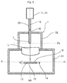
Dans le mode de réalisation illustré en
Un premier boîtier 31, de préférence hermétique, renferme la masse sismique 12 de manière à la protéger de l'atmosphère environnante, de la poussière ou de rayonnements parasites. La lentille 30 est montée hermétiquement sur le boîtier 31, par exemple, à l'aide d'un joint. En variante, le premier boîtier 31 n'est pas hermétique, mais étanche ou simplement fermé de manière à offrir une protection mécanique et optique. Les fibre optiques émettrice 10, et réceptrice 20 sont situées à l'extérieur du boîtier 31, leurs extrémités 8, 9 étant à distance focale de la lentille 30, de manière à, respectivement, injecter et recevoir le faisceau lumineux L. Un deuxième boîtier 32, monté accolé au premier boîtier 31, forme un compartiment fermé autour de la lentille 30 et de la portion terminale des fibres optiques 10, 20. L'interface entre le deuxième boîtier 32 et les fibres émettrice 10 et réceptrice 20 qui en émergent, est réalisée à l'aide d'un joint, ou d'une pièce rigide assurant un maintien desdites fibres, et une obstruction mécanique et optique.A
Le fonctionnement du capteur d'accélération 1 selon l'invention est le suivant : En l'absence d'accélération, la surface réfléchissante 16 est perpendiculaire 20, à l'axe AA. Le faisceau lumineux L, émis par la fibre émettrice 10, traverse la lentille convergente 30 dont il ressort collimaté et dévié par rapport à la direction AA. Il frappe la surface réfléchissante 16 sous un angle d'incidence β, et est réfléchi sous ce même angle en direction de la lentille 30, dont il ressort parallèle à l'axe AA. Il est alors collecté par la fibre réceptrice 20, qui transmet un signal optique au détecteur 21. Grâce au décalage latéral initial des fibres 10, 20, le faisceau lumineux L impactant la fibre réceptrice 20 en position neutre, est décalé latéralement par rapport au coeur 19 de la fibre 20 de manière à transmettre uniquement 50 pourcents de l'intensité émise. Ce décalage initial du spot d'impact S sur l'extrémité 9 de la fibre réceptrice 20 est illustré en
Ces valeurs sont indicatives, car la sensibilité du capteur d'accélération 1 dépend de la lentille 30 utilisée et de la sensibilité de la masse sismique 12 elle-même. Mais, à titre de comparaison avec l'accéléromètre divulgué dans le document
On se réfère maintenant à la
La
Ainsi a été décrit un capteur d'accélération de type optique, performant et facile à intégrer, grâce à sa structure innovante, en particulier grâce à l'utilisation d'une lentille convergente. Bien entendu, la présente invention ne se limite pas aux modes de réalisation décrits ci-dessus, mais s'étend à toutes les variantes à la portée de l'homme de métier, s'inscrivant dans le cadre des revendications ci-après.Thus has been described an optical type acceleration sensor, efficient and easy to integrate, thanks to its innovative structure, especially through the use of a convergent lens. Of course, the present invention is not limited to the embodiments described above, but extends to all variants within the scope of those skilled in the art, falling within the scope of the claims below.
Claims (12)
Applications Claiming Priority (1)
| Application Number | Priority Date | Filing Date | Title |
|---|---|---|---|
| CH01222/15A CH711448A1 (en) | 2015-08-25 | 2015-08-25 | Optical acceleration sensor. |
Publications (1)
| Publication Number | Publication Date |
|---|---|
| EP3136113A1 true EP3136113A1 (en) | 2017-03-01 |
Family
ID=54014459
Family Applications (1)
| Application Number | Title | Priority Date | Filing Date |
|---|---|---|---|
| EP16185686.9A Withdrawn EP3136113A1 (en) | 2015-08-25 | 2016-08-25 | Optical acceleration sensor |
Country Status (3)
| Country | Link |
|---|---|
| US (1) | US20170059606A1 (en) |
| EP (1) | EP3136113A1 (en) |
| CH (1) | CH711448A1 (en) |
Families Citing this family (2)
| Publication number | Priority date | Publication date | Assignee | Title |
|---|---|---|---|---|
| US20180031599A1 (en) * | 2016-07-27 | 2018-02-01 | Khalifa University of Science and Technology | Optically enabled micro-disk inertia sensor |
| US10976338B2 (en) * | 2017-09-11 | 2021-04-13 | Optilab, Llc | Apparatus and method for sensing acceleration or force using fiber Bragg grating (FBG) |
Citations (8)
| Publication number | Priority date | Publication date | Assignee | Title |
|---|---|---|---|---|
| US4403144A (en) * | 1978-07-26 | 1983-09-06 | Rockwell International Corporation | Fiber optic accelerometer |
| EP0151957A2 (en) * | 1984-01-25 | 1985-08-21 | Asea Ab | Accelerometer |
| JPS6123974A (en) * | 1984-07-12 | 1986-02-01 | Hitachi Cable Ltd | Two-dimensional acceleration sensor for optical fiber |
| US5437186A (en) | 1991-11-06 | 1995-08-01 | Tschulena; Guido | Integrated optical acceleration sensor |
| US20060192974A1 (en) * | 2005-02-01 | 2006-08-31 | Chian Chiu Li | Interferometric MOEMS Sensor |
| US20070247613A1 (en) | 2006-04-24 | 2007-10-25 | Mathieu Cloutier | Fiber optic accelerometer |
| WO2007126475A2 (en) * | 2006-04-26 | 2007-11-08 | Davidson Instruments, Inc. | Fiber optic mems seismic sensor with mass supported by hinged beams |
| US8770024B1 (en) | 2013-07-05 | 2014-07-08 | Vibrosound Ltd. | Fiber optic accelerometer |
-
2015
- 2015-08-25 CH CH01222/15A patent/CH711448A1/en not_active Application Discontinuation
-
2016
- 2016-08-25 US US15/246,759 patent/US20170059606A1/en not_active Abandoned
- 2016-08-25 EP EP16185686.9A patent/EP3136113A1/en not_active Withdrawn
Patent Citations (8)
| Publication number | Priority date | Publication date | Assignee | Title |
|---|---|---|---|---|
| US4403144A (en) * | 1978-07-26 | 1983-09-06 | Rockwell International Corporation | Fiber optic accelerometer |
| EP0151957A2 (en) * | 1984-01-25 | 1985-08-21 | Asea Ab | Accelerometer |
| JPS6123974A (en) * | 1984-07-12 | 1986-02-01 | Hitachi Cable Ltd | Two-dimensional acceleration sensor for optical fiber |
| US5437186A (en) | 1991-11-06 | 1995-08-01 | Tschulena; Guido | Integrated optical acceleration sensor |
| US20060192974A1 (en) * | 2005-02-01 | 2006-08-31 | Chian Chiu Li | Interferometric MOEMS Sensor |
| US20070247613A1 (en) | 2006-04-24 | 2007-10-25 | Mathieu Cloutier | Fiber optic accelerometer |
| WO2007126475A2 (en) * | 2006-04-26 | 2007-11-08 | Davidson Instruments, Inc. | Fiber optic mems seismic sensor with mass supported by hinged beams |
| US8770024B1 (en) | 2013-07-05 | 2014-07-08 | Vibrosound Ltd. | Fiber optic accelerometer |
Also Published As
| Publication number | Publication date |
|---|---|
| US20170059606A1 (en) | 2017-03-02 |
| CH711448A1 (en) | 2017-02-28 |
Similar Documents
| Publication | Publication Date | Title |
|---|---|---|
| EP0050539A1 (en) | Video imaging system for a homing-head | |
| FR2613477A1 (en) | OPTICAL DISPLACEMENT AND PRESSURE SENSOR | |
| EP0255792A1 (en) | Identification system using a retroreflection assembly and a laser beam modulator | |
| FR2569841A1 (en) | OPTOELECTRO-MECHANICAL MEASURING DEVICE, IN PARTICULAR FOR MEASURING PRESSURE AND FORCE VALUES | |
| EP3136113A1 (en) | Optical acceleration sensor | |
| US6895144B2 (en) | Structure and method for manufacturing compact optical power monitors of highly reliable performance | |
| EP2290430A1 (en) | System for measuring the variation of an optical line of sight of an optical instrument | |
| FR2960063A1 (en) | DEVICE FOR OPTICALLY MEASURING A PHYSICAL PARAMETER | |
| FR3020585A1 (en) | HEAD FOR WELDING DEVICE | |
| CA2057943A1 (en) | Interferometric microdisplacement sensor analysis device | |
| US20040208442A1 (en) | Optical signal parameter monitor based on integrated tapping platform | |
| EP0151057B1 (en) | Velocity-interferometer with continuously variable sensibility | |
| EP0390648B1 (en) | Multidirectional contact sensor for control machines | |
| EP0023902B1 (en) | Optical device for regulation and adjustment of light | |
| EP1943527B1 (en) | Accelerometer for measuring vibrations with an optical sensor | |
| FR2531232A1 (en) | OPTICAL SELF-DIAGRAM SYSTEM WITH IMAGING | |
| CH644948A5 (en) | Optical method for detecting and/or measuring physical quantities, and device for implementing this method | |
| FR2567651A1 (en) | Equipment for measuring the speed of a projectile by interferometry using a laser beam propagated by a single optical waveguide | |
| US6281488B1 (en) | Fiber optic coupled optical sensor | |
| EP2625557B1 (en) | Optical head for atmospheric measurement, related systems and manufacturing methods | |
| EP0048688A2 (en) | Method to detect optically and/or to measure a deformation and/or a displacement of an object or part of an object, device to carry out the method and use of the method | |
| FR2630956A1 (en) | ELASTICALLY DEFORMABLE CONNECTION DEVICE WITH SECURITY THRESHOLD OF AT LEAST TWO MOVABLE PARTS TOGETHER | |
| BE1009299A3 (en) | Detection method and device for the use of said method | |
| WO2020074800A1 (en) | Dark-field optical inspecting device | |
| EP3832400A1 (en) | Device and method for measuring strokes of a timepiece |
Legal Events
| Date | Code | Title | Description |
|---|---|---|---|
| PUAI | Public reference made under article 153(3) epc to a published international application that has entered the european phase |
Free format text: ORIGINAL CODE: 0009012 |
|
| STAA | Information on the status of an ep patent application or granted ep patent |
Free format text: STATUS: THE APPLICATION HAS BEEN PUBLISHED |
|
| AK | Designated contracting states |
Kind code of ref document: A1 Designated state(s): AL AT BE BG CH CY CZ DE DK EE ES FI FR GB GR HR HU IE IS IT LI LT LU LV MC MK MT NL NO PL PT RO RS SE SI SK SM TR |
|
| AX | Request for extension of the european patent |
Extension state: BA ME |
|
| STAA | Information on the status of an ep patent application or granted ep patent |
Free format text: STATUS: THE APPLICATION IS DEEMED TO BE WITHDRAWN |
|
| 18D | Application deemed to be withdrawn |
Effective date: 20170902 |