EP3136526A1 - Ground fault protection methods - Google Patents
Ground fault protection methods Download PDFInfo
- Publication number
- EP3136526A1 EP3136526A1 EP15182373.9A EP15182373A EP3136526A1 EP 3136526 A1 EP3136526 A1 EP 3136526A1 EP 15182373 A EP15182373 A EP 15182373A EP 3136526 A1 EP3136526 A1 EP 3136526A1
- Authority
- EP
- European Patent Office
- Prior art keywords
- power converter
- switching frequency
- ground fault
- power
- zero sequence
- Prior art date
- Legal status (The legal status is an assumption and is not a legal conclusion. Google has not performed a legal analysis and makes no representation as to the accuracy of the status listed.)
- Granted
Links
- 238000000034 method Methods 0.000 title claims abstract description 183
- 230000004224 protection Effects 0.000 title claims description 12
- 230000008569 process Effects 0.000 claims abstract description 149
- 238000010183 spectrum analysis Methods 0.000 claims abstract description 65
- 230000008878 coupling Effects 0.000 claims abstract description 27
- 238000010168 coupling process Methods 0.000 claims abstract description 27
- 238000005859 coupling reaction Methods 0.000 claims abstract description 27
- 239000004065 semiconductor Substances 0.000 claims abstract description 14
- 238000001514 detection method Methods 0.000 claims description 38
- 239000003990 capacitor Substances 0.000 claims description 34
- 238000001228 spectrum Methods 0.000 claims description 28
- 230000001681 protective effect Effects 0.000 claims description 15
- 230000004044 response Effects 0.000 claims description 5
- 238000011217 control strategy Methods 0.000 description 8
- 238000002955 isolation Methods 0.000 description 7
- 238000005259 measurement Methods 0.000 description 7
- 230000007935 neutral effect Effects 0.000 description 7
- 230000003595 spectral effect Effects 0.000 description 7
- 230000000977 initiatory effect Effects 0.000 description 6
- 230000001360 synchronised effect Effects 0.000 description 5
- 230000009979 protective mechanism Effects 0.000 description 4
- 238000005070 sampling Methods 0.000 description 4
- 230000002159 abnormal effect Effects 0.000 description 3
- 238000004891 communication Methods 0.000 description 3
- 230000008901 benefit Effects 0.000 description 2
- 230000001934 delay Effects 0.000 description 2
- 230000000694 effects Effects 0.000 description 2
- 230000006870 function Effects 0.000 description 2
- 230000006872 improvement Effects 0.000 description 2
- 238000009413 insulation Methods 0.000 description 2
- 230000003071 parasitic effect Effects 0.000 description 2
- 238000012545 processing Methods 0.000 description 2
- 230000002776 aggregation Effects 0.000 description 1
- 238000004220 aggregation Methods 0.000 description 1
- 230000001010 compromised effect Effects 0.000 description 1
- 230000001419 dependent effect Effects 0.000 description 1
- 238000013461 design Methods 0.000 description 1
- 238000006073 displacement reaction Methods 0.000 description 1
- 238000005553 drilling Methods 0.000 description 1
- 239000011159 matrix material Substances 0.000 description 1
- 230000001902 propagating effect Effects 0.000 description 1
- 230000001141 propulsive effect Effects 0.000 description 1
- 230000009467 reduction Effects 0.000 description 1
- 230000001172 regenerating effect Effects 0.000 description 1
- 230000008439 repair process Effects 0.000 description 1
- 230000003068 static effect Effects 0.000 description 1
Images


Classifications
-
- H—ELECTRICITY
- H02—GENERATION; CONVERSION OR DISTRIBUTION OF ELECTRIC POWER
- H02H—EMERGENCY PROTECTIVE CIRCUIT ARRANGEMENTS
- H02H7/00—Emergency protective circuit arrangements specially adapted for specific types of electric machines or apparatus or for sectionalised protection of cable or line systems, and effecting automatic switching in the event of an undesired change from normal working conditions
- H02H7/26—Sectionalised protection of cable or line systems, e.g. for disconnecting a section on which a short-circuit, earth fault, or arc discharge has occured
-
- G—PHYSICS
- G01—MEASURING; TESTING
- G01R—MEASURING ELECTRIC VARIABLES; MEASURING MAGNETIC VARIABLES
- G01R31/00—Arrangements for testing electric properties; Arrangements for locating electric faults; Arrangements for electrical testing characterised by what is being tested not provided for elsewhere
- G01R31/08—Locating faults in cables, transmission lines, or networks
- G01R31/081—Locating faults in cables, transmission lines, or networks according to type of conductors
- G01R31/086—Locating faults in cables, transmission lines, or networks according to type of conductors in power transmission or distribution networks, i.e. with interconnected conductors
-
- G—PHYSICS
- G01—MEASURING; TESTING
- G01R—MEASURING ELECTRIC VARIABLES; MEASURING MAGNETIC VARIABLES
- G01R31/00—Arrangements for testing electric properties; Arrangements for locating electric faults; Arrangements for electrical testing characterised by what is being tested not provided for elsewhere
- G01R31/50—Testing of electric apparatus, lines, cables or components for short-circuits, continuity, leakage current or incorrect line connections
- G01R31/52—Testing for short-circuits, leakage current or ground faults
-
- H—ELECTRICITY
- H02—GENERATION; CONVERSION OR DISTRIBUTION OF ELECTRIC POWER
- H02H—EMERGENCY PROTECTIVE CIRCUIT ARRANGEMENTS
- H02H1/00—Details of emergency protective circuit arrangements
- H02H1/0007—Details of emergency protective circuit arrangements concerning the detecting means
-
- H—ELECTRICITY
- H02—GENERATION; CONVERSION OR DISTRIBUTION OF ELECTRIC POWER
- H02H—EMERGENCY PROTECTIVE CIRCUIT ARRANGEMENTS
- H02H3/00—Emergency protective circuit arrangements for automatic disconnection directly responsive to an undesired change from normal electric working condition with or without subsequent reconnection ; integrated protection
- H02H3/16—Emergency protective circuit arrangements for automatic disconnection directly responsive to an undesired change from normal electric working condition with or without subsequent reconnection ; integrated protection responsive to fault current to earth, frame or mass
- H02H3/162—Emergency protective circuit arrangements for automatic disconnection directly responsive to an undesired change from normal electric working condition with or without subsequent reconnection ; integrated protection responsive to fault current to earth, frame or mass for ac systems
-
- G—PHYSICS
- G01—MEASURING; TESTING
- G01R—MEASURING ELECTRIC VARIABLES; MEASURING MAGNETIC VARIABLES
- G01R19/00—Arrangements for measuring currents or voltages or for indicating presence or sign thereof
- G01R19/25—Arrangements for measuring currents or voltages or for indicating presence or sign thereof using digital measurement techniques
- G01R19/2513—Arrangements for monitoring electric power systems, e.g. power lines or loads; Logging
-
- G—PHYSICS
- G01—MEASURING; TESTING
- G01R—MEASURING ELECTRIC VARIABLES; MEASURING MAGNETIC VARIABLES
- G01R23/00—Arrangements for measuring frequencies; Arrangements for analysing frequency spectra
- G01R23/16—Spectrum analysis; Fourier analysis
-
- Y—GENERAL TAGGING OF NEW TECHNOLOGICAL DEVELOPMENTS; GENERAL TAGGING OF CROSS-SECTIONAL TECHNOLOGIES SPANNING OVER SEVERAL SECTIONS OF THE IPC; TECHNICAL SUBJECTS COVERED BY FORMER USPC CROSS-REFERENCE ART COLLECTIONS [XRACs] AND DIGESTS
- Y04—INFORMATION OR COMMUNICATION TECHNOLOGIES HAVING AN IMPACT ON OTHER TECHNOLOGY AREAS
- Y04S—SYSTEMS INTEGRATING TECHNOLOGIES RELATED TO POWER NETWORK OPERATION, COMMUNICATION OR INFORMATION TECHNOLOGIES FOR IMPROVING THE ELECTRICAL POWER GENERATION, TRANSMISSION, DISTRIBUTION, MANAGEMENT OR USAGE, i.e. SMART GRIDS
- Y04S10/00—Systems supporting electrical power generation, transmission or distribution
- Y04S10/50—Systems or methods supporting the power network operation or management, involving a certain degree of interaction with the load-side end user applications
- Y04S10/52—Outage or fault management, e.g. fault detection or location
Definitions
- the present invention relates to ground fault protection of power distribution systems, particularly those systems in which a plurality of power converter systems are interconnected by a point of common coupling without the use of isolating transformers or any form of low resistance grounding network.
- the present invention addresses the difficulty in achieving ground fault discrimination in such "floating" or high resistance grounded systems.
- FIG. 1 An example of a conventional transformerless, high resistance grounded, power distribution system is shown in Figure 1 .
- the power distribution system 1 provides power to four VSD systems 2 1 -2 4 .
- Each VSD system 2 is electrically connected to a distribution bus 5 that defines a point of common coupling and includes a power converter 3 of the back to back pulse width modulation (PWM) voltage source inverter (VSI) type and an ac line filter 6.
- PWM back to back pulse width modulation
- VSI back to back pulse width modulation
- ac line filter 6 an electrical machine 7 (e.g., a motor)
- the power distribution system 1 shown in Figure 1 is for a marine vessel (e.g., a ship, drilling rig or any other surface-going vessel or platform or submersible (submarine) vessel) but it will be understood that similar power distribution systems can be used for other applications.
- a marine vessel e.g., a ship, drilling rig or any other surface-going vessel or platform or submersible (submarine) vessel
- similar power distribution systems can be used for other applications.
- Each power converter 3 includes a supply bridge 3A having ac terminals electrically connected to a distribution bus 5 and a machine bridge 3B electrically connected to the electrical machine 7.
- the machine bridge 3B will often be directly connected to the electrical machine 7, but it can also be indirectly connected by a filter, e.g., a sine wave filter.
- the dc output of each supply bridge 3A is electrically connected to the dc input of the machine bridge 3B by a dc link 3C.
- the supply bridge 3A and machine bridge 3B are active rectifier/inverters with a plurality of semiconductor switching devices controlled using a PWM strategy.
- the supply bridge 3A of each power converter 3 is electrically connected to the distribution bus 5 by the ac line filter 6.
- Each ac line filter 6 includes a first filter reactor 6A, a second filter reactor 6B and an additional filter component 6C.
- the ac line filter 6 also includes a filter capacitor 6D that is connected to ground.
- the subscripts 1 to 4 are used to indicate components or operating parameters of the first, second, third and fourth VSD systems 2 1 -2 4 , respectively. This includes indicating components or operating parameters of the power converter 3 and the ac line filter 6.
- the supply bridge 3A 1 is the supply bridge of the first power converter 3 1 which forms part of the first VSD system 2 1 .
- each supply bridge 3A will operate as an active rectifier to supply power to the dc link 3C and each machine bridge 3B will operate as an inverter to supply power to the respective machine 7.
- the direction of power flow may be reversed, e.g., if a particular machine 7 is operated in a generating mode or experiencing regenerative braking where power is supplied to the distribution bus 5.
- the machine bridge 3B of the associated VSD system 2 will operate as an active rectifier to supply power from the machine 7 to the dc link 3C and the supply bridge 3A will operate as an inverter to supply power to the distribution bus 5.
- Generators 4 supply power to the distribution bus 5.
- the power distribution system 1 will typically include a first bus section and a second bus section that are interconnected by a bus tie. Some power distribution systems use a plurality of bus sections interconnected by a plurality of bus ties to improve power availability.
- the direction of power flow is generally from the generators 4 to the machines 7 1 -7 4 through the distribution bus 5, the ac line filters 6 1 -6 4 and the respective power converters 3 1 -3 4 .
- the normal working mean voltage to ground throughout the power distribution system 1 is defined by at least one high resistance grounding resistor 8 whereas the non zero frequency symmetry of the normal working ac phase voltage relative to ground is defined by the capacitance to ground of the ac line filters 6 1 -6 4 .
- the voltages to ground throughout the power distribution system 1 experience perturbations from their normal working conditions and these perturbations are dependent on the nature and location of the ground fault. These ground faults also cause abnormal zero sequence currents to flow throughout the power distribution system 1.
- zero sequence current refers to the residual component of current after summation of the individual ac line currents of a polyphase system. It will be readily appreciated that the zero sequence currents do not experience phase rotation. Since such a power distribution system is typically extensive and includes a number of items of equipment that routinely generate common mode voltages and/or have deliberate or parasitic capacitance to ground, it is generally the case that a wide spectrum of zero sequence currents flow throughout the system when in normal operation, albeit of controlled magnitude.
- a type 1 ground fault is a ground fault in one of the supply ac lines 9 1 -9 4 (i.e., the ac lines between the distribution bus 5 and the respective supply bridge 3A 1 -3A 4 , including the ac line filter 6 1 -6 4 ), a type 2 ground fault is a ground fault in the dc link 3C of the power converter and a type 3 ground fault is a ground fault in one of the machine ac lines 10 1 -10 4 (i.e., the ac lines between the machine bridge 3B and the respective machine 7 1 -7 4 ). If each VSD drive includes a filter, e.g., a sine wave filter (not shown), between the machine bridge and the machine, a type 3 ground fault will typically have similar characteristics to a type 1 ground fault.
- a filter e.g., a sine wave filter (not shown)
- Zero sequence currents are typically detected by core balance current transformers (CBCTs) and simplistic detectors. But these devices have only a limited ability to discriminate between zero sequence fault currents and the zero sequence currents associated with normal operation. This discrimination can be made ineffective when zero sequence fault currents flow in healthy or non-faulted equipment as a result of the above perturbations in voltages to ground when a ground fault is present, and in the worst case can result in the unnecessary tripping of non-faulted equipment.
- CBCTs core balance current transformers
- a dedicated pulse generator injects a known spectrum of zero sequence voltages into the distribution bus at a high level in the power distribution system.
- the current transformers and a specialised detector are used to identify the abnormal zero sequence currents that are associated with a ground fault in a particular branch of the power distribution system.
- This method is calibrated to measure branch insulation resistance, despite there potentially being a large distributed capacitance to ground. In practice, this method has inadequate signal to noise ratio to operate effectively in systems that employ back to back PWM VSIs with significant supply side capacitive ac line filters.
- VSD systems are similar to the VSD systems 2 1 -2 4 shown in Figure 1 but the coupling between the distribution bus 5 and the ac line filter 6 is by means of a transformer, which provides galvanic isolation.
- the common mode voltages CMV1 and CMV2 may be detected when a type 1, type 2, or type 3 ground fault is present. For example, when a supply isolation transformer is used, this provides common mode voltage isolation between the distribution bus and the associated VSD system and it is common practice to sense the voltage between the mid-point of the dc link 3C and ground in order to locate a ground fault. This also allows the ground fault type to be discriminated as follows:
- the voltage offsets that are experienced in the cases of type 2 and type 3 ground faults include all spectral components of the respective phase voltage, i.e., a classical PWM spectrum, and it is known for the detection of these voltages to be performed by techniques ranging from the use of passively filtered detectors to sophisticated signature-based detectors. When signature-based detectors are used, these are based upon the principle that the detector will have an inbuilt knowledge of the PWM spectra of the associated power converter.
- the common mode voltages CMV1 and CMV2 may be detected in all of the VSD systems 2 1 -2 4 that are electrically connected to the point of common coupling provided by the distribution bus 5 when a ground fault of type 1, type 2, or type 3 is present in just one of the VSD systems.
- Such power distribution systems are commonly known as transformerless systems and are known not to be capable of providing ground fault protection discrimination when the above types of common mode voltage detection are employed.
- the voltage sensing method has also been applied to ac lines by detecting the voltage between an artificial neutral point (the mid-point of a star (wye) connected resistive network) and ground. This form of voltage sensing is also compromised when a supply isolation transformer is not provided.
- the above-described method of detecting zero sequence currents using CBCTs and RMS detectors has been enhanced to allow the spectral content of the zero sequence component of ac line currents to be resolved in order to determine whether normal or ground faulted conditions are present.
- the common mode voltages CMV1 and CMV2 in being impressed upon all parts of the power distribution system, cause zero sequence currents to be detected in all of the VSD systems that are electrically connected to the point of common coupling provided by the distribution bus when a ground fault of type 1, type 2, or type 3 is present in just one of the VSD systems.
- ground fault-related zero sequence currents into the ac line filters of otherwise healthy or non-faulted VSD systems is governed by the interconnecting zero sequence impedances and the nature of the ac line filters - it generally being the case that these ac line filters have significant capacitance to ground in order to comply with Electromagnetic Compatibility (EMC) legislation.
- EMC Electromagnetic Compatibility
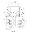
- the representative power distribution system 1' of Figure 2 is similar to the power distribution system 1 shown in Figure 1 and like components have been given the same reference numeral.
- the power distribution system 1' includes a distribution bus 5, which defines a point of common coupling between interconnected branches, and conventional circuit breaker/switchgear arrangements to allow connection of a generator 4, a first VSD system 2 1 and a second VSD system 2 2 to the distribution bus.
- the first VSD system 2 1 includes a first power converter 3 1 of the back to back PWM VSI type and a first ac line filter 6 1 and is used to interface a first electrical machine 7 1 (e.g., a motor) to the distribution bus 5.
- the second VSD system 2 2 includes a second power converter 3 2 of the back to back PWM VSI type and a second ac line filter 6 2 and is used to interface a second electrical machine 7 2 (e.g. a motor) to the distribution bus 5.
- the first common mode voltage CMV1 of the supply bridge 3A 1 is continuously applied between the mid-point of the dc link 3C 1 and the neutral point of the ac lines 9 1 of the supply bridge
- the common mode voltage CMV2 of the machine bridge 3B 1 is continuously applied between the neutral point of the machine ac lines 10 1 and the mid-point of the dc link 3C 1 . It therefore follows that the sum of common mode voltages CMV1 and CMV2 is continuously applied between the neutral point of the supply ac lines 9 1 and the neutral point of the machine ac lines 10 1 .
- the magnitudes of the individual spectral components of the common mode voltages CMV1 and CMV2 are substantially pro rota with the dc link voltage and vary additionally according to the modulation depth of the supply bridge 3A 1 and the machine bridge 3B 1 respectively.
- the fundamental component of the PWM switching frequency that is applicable to the supply bridge 3A 1 and the machine bridge 3B 1 is present in the common mode voltages CMV1 and CMV2, respectively, at all practically useful modulation depths.
- the voltage to ground at any point in the representative power distribution system 1' is governed by the relative levels of impedances to ground throughout the system - these impedances generally being capacitive, and ground faults typically having a dominantly low resistive impedance to ground and therefore defining the voltages to ground elsewhere in the system.
- These voltages to ground and impedances to ground define the currents that flow to ground, i.e., the zero sequence currents. It therefore follows that zero sequence currents are a maximum when a ground fault is present.
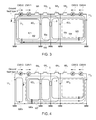
- the magnitude of zero sequence fault currents is defined by common mode voltages CMV1 and CMV2, the zero sequence impedance of the second filter reactor 6B 1 , the impedance of the EMC filter capacitor 6D 1 , and stray interconnecting impedances (not shown). These stray impedances are minimised by design in the interest of EMC and will be described in more detail below with reference to the third and fourth modes.
- the type 3 ground fault also causes the common mode voltage that is applied to the EMC filter capacitor 6D 1 to be increased.
- This voltage is also generally applied to equipment that is electrically connected to the point of common coupling but its amplitude is progressively and only slightly reduced as it propagates through the zero sequence impedance of the first filter reactor 6A 1 , the zero sequence impedances of the distribution bus 5, the zero sequence impedance of the first filter reactor 6A 2 of the second ac line filter 6 2 , and then to the EMC filter capacitor 6D 2 of the second ac line filter.
- the zero sequence fault currents then return to the site of the ground fault at the machine ac lines 10 1 .
- This propagation is the second mode of propagation (labelled 'M2').
- the spectra of zero sequence fault currents that flow in the EMC filter capacitor 6D 1 , the first filter reactor 6A 1 , the first filter reactor 6A 2 and the EMC filter capacitor 6D 2 are closely related in as much as they share the same source of common mode voltage, i.e., CMV1 and CMV2, and the degree of attenuation in the first filter reactor 6A 2 and the EMC filter capacitor 6D 2 of the second ac line filter 6 2 , progressively increases in significance as harmonic order increases. It will be readily appreciated that the zero sequence fault currents that flow in the EMC filter capacitor 6D 1 , the first filter reactor 6A 1 , the first filter reactor 6A 2 and the EMC filter capacitor 6D 2 are phase shifted relative to one another according to their impedances.
- the supply bridge 3A 2 and the machine bridge 3B 2 of the second VSD system 2 2 have respective common mode voltages CMV3 and CMV4 that are of similar form to the common mode voltages CMV1 and CMV2. In practice, they may be identical to the common mode voltages CMV1 and CMV2 when similar operating conditions are experienced by the first and second VSD systems 2 1 , 2 2 .
- a third mode of propagation of zero sequence fault currents (labelled 'M3') exists because the stator main wall insulation of the electrical machine 7 2 has a significant distributed capacitance 11 2 to ground and this provides a path between the machine ac lines 10 2 and local ground (i.e., the local point of connection in the ground network).
- the form of the third mode M3 is similar to that of the first mode M1 and the zero sequence fault currents are of a similar nature to those that flow in the first mode.
- the impedance of the distributed capacitance 11 2 to ground is generally greater than the impedance of the ground faults and the magnitude of current in the third mode M3 that flows in the EMC filter capacitor 6D 2 is generally less than the zero sequence fault currents of the first and second modes M1, M2.
- the zero sequence fault currents that flow in the third mode M3 commonly have similar frequency characteristics to those of the first and second modes M1, M2.
- common mode voltages CMV3 and CMV4 also cause a fourth mode (labelled 'M4') of propagation of zero sequence fault currents.
- the form of the fourth mode M4 is similar to that of the second mode M2 and the zero sequence fault currents are of a similar nature to those that flow in the second mode.
- the impedance of the distributed capacitance 11 2 to ground is generally greater than the impedance of the ground faults and the magnitude of zero sequence fault currents in the fourth mode M4 that flows in the EMC filter capacitor 6D 1 of the first ac line filter 6 1 is generally less than the zero sequence fault currents of the first, second and third modes M1-M3.
- the zero sequence fault currents that flow in the fourth mode M4 commonly have similar frequency characteristics to those of the first and second modes M1, M2.
- a fifth mode also exists encompassing all four common mode voltages CMV1, CMV2, CMV3 and CMV4 and with currents flowing between the ground fault and distributed capacitance 11 2 to ground.
- the magnitude of the zero sequence fault currents that flow in the fifth mode M5 are generally less than the zero sequence fault currents of the first, second, third and fourth modes M1-M4 and comprises the frequencies associated with the summation of all four common mode voltages.
- the magnitude of the various sequence fault current propagation modes is M1>M2>M3>M4>M5.
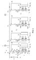
- Figure 3 also shows the current circulation paths through the high resistance grounding resistor 8.
- the high impedance of this resistor causes currents that pass through this resistor to have a relatively small magnitude.
- the modes that flow in the high resistance grounding resistor 8 are labelled 'Ma' and 'Mb'.
- the first circulating current path of the sixth mode M6a is similar to the first mode M1 of propagation of zero sequence fault currents, the difference being that the common mode voltage CMV2 is no longer summated with the common mode voltage CMV1 because the ground reference point is now in either the positive or negative terminal of the dc link 3C 1 according to the location of the ground fault.
- This ground reference point is also applicable to the common mode voltage CMV2 of the machine bridge 3B 1 and this causes the second circulating current path of the sixth mode M6b to exist.
- the first circulating current path of the sixth mode of propagation of zero sequence fault currents is associated with a seventh mode of propagation of zero sequence fault currents (labelled 'M7').
- the seventh mode M7 is similar to the second mode M2 but in this case the mode of propagation of zero sequence fault currents is not excited by the common mode voltage CMV2 of the machine bridge 3B 1 .
- Eighth and ninth modes of propagation of zero sequence fault currents are equivalent to the third and fourth modes M3, M4.
- a tenth mode of propagation of zero sequence fault currents (labelled 'M10') is similar to the fifth mode M5. However, it will be readily appreciated that the eighth, ninth and tenth modes are not exited by the common mode voltage CMV2 of the machine bridge 3B 1 .
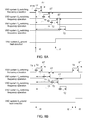
- Type 1 ground fault
- a single phase equivalent circuit showing the modes of propagation during a type 1 ground fault has not been included because the propagation between VSD systems is greatly reduced as a result of the voltage to ground of the distribution bus being set by the ground fault.
- the propagation of zero sequence fault currents in the distribution bus 5 is dominated by a first current component that is defined by the fundamental component of the ac power distribution phase voltage and the ohmic value of the high resistance grounding resistor 8.
- the second mode M2 of propagation of zero sequence fault currents is also effective and these respective currents are superimposed upon the first current component.
- a conventional high resistance ground current detection process i.e., a detection process that is generally responsive to the fundamental component of the distribution voltage frequency
- this detection process is generally rendered non-responsive to the circulating currents that are defined by the second mode M2 of propagation of zero sequence fault currents as a result of careful selection of the high resistance grounding resistor 8 and the capacitance to ground of the EMC filter capacitor 6D of the ac line filter 6.
- the EMC filter capacitance is defined with the specific objective of reducing the high frequency spectral content of common mode voltage that is experienced throughout the distribution bus 5.
- VSD systems typically have more than one generator and more than two VSD systems.
- the VSD systems are generally identical or at least have identical modular power electronics and PWM control strategies for reasons of system simplification, economy and reduced spares holding.
- PWM control strategies for reasons of system simplification, economy and reduced spares holding.
- the present invention provides a ground fault protection method for a power distribution system comprising a plurality of power converter systems electrically connected to a point of common coupling (e.g., a distribution bus), each power converter system including a power converter with a plurality of semiconductor switching devices controlled using a pulse width modulation (PWM) strategy with a switching frequency, the method comprising applying a spectrum analysis process to each power converter system that uses measured or derived zero sequence currents associated with the respective power converter system to determine the location of a ground fault within the power distribution system, and a switching frequency process where the switching frequency of the power converter of at least one of the power converter systems is different from the switching frequency of the power converter of at least another one of the power converter systems (i.e., so that the power converters of at least two of the plurality of power converter systems have a different switching frequency) during at least part of the time that the spectrum analysis process is applied.
- PWM pulse width modulation
- the present invention further provides a power distribution system comprising a plurality of power converter systems electrically connected to a point of common coupling, each power converter system including a power converter with a plurality of semiconductor switching devices controlled using a PWM strategy with a switching frequency, wherein the power distribution system further includes a controller for each power converter system, each controller being adapted to apply a spectrum analysis process to the respective power converter system that uses measured or derived zero sequence currents associated with the respective power converter system to determine the location of a ground fault within the power distribution system, and each controller being adapted to apply a switching frequency process where the switching frequency of the power converter of at least one of the power converter systems is different from the switching frequency of the power converter of at least another one of the power converter systems during at least part of the time that the spectrum analysis process is applied.
- the spectrum analysis process can also be used to initially detect the presence of a ground fault at an unspecified location within the power distribution system.
- the spectrum analysis process applied to each power converter system can comprise the steps of:
- the frequency component within the zero sequence current frequency spectrum will normally be the fundamental component or an integer or non-integer harmonic component of the switching frequency of the power converter of the respective power converter system. For example, if a power converter has a switching frequency (or carrier frequency) of 2.5 kHz, the frequency component will normally be 2.5 kHz or an integer or non-integer harmonic component of 2.5 kHz.
- the amplitude of two or more different frequency components can be derived simultaneously within the zero sequence current frequency spectrum and each amplitude can be compared against a respective threshold or stored amplitude(s).
- Additional frequency components within the zero sequence current frequency spectrum can be the fundamental component or an integer or non-integer harmonic component of the distribution voltage frequency (e.g., 50 or 60 Hz for a conventional power distribution system) and the fundamental component or an integer or non-integer harmonic component of the machine stator or load voltage frequency.
- the additional frequency components can optionally be used to determine the location of the ground fault within the respective power converter system, i.e., to determine if the ground fault is a type 1, type 2 or type 3 ground fault where appropriate.
- the amplitude of the frequency component(s) within the zero sequence current frequency spectrum can be derived using any suitable and time-efficient digital signal processing (DSP) technique including inter alia synchronous discrete Fourier transform (DFT), Goertzel algorithm (or filter) and heterodyne with frequency.
- DSP digital signal processing
- DFT synchronous discrete Fourier transform
- Goertzel algorithm or filter
- heterodyne with frequency The spectrum analysis process is used to reliably and rapidly detect the amplitude of the frequency component(s) within the complete spectrum of zero sequence currents.
- Each frequency component is known and can be provided as an input to the spectrum analysis process.
- the controllers will normally be provided with data that includes inter alia the prevailing PWM switching frequency, the distribution voltage frequency and the machine stator or load voltage frequency to allow the controllers to carry out routine operational control of the power converters.
- the sampling rate of a synchronous DFT is preferably synchronised to the PWM generator for the respective power converter.
- the Goertzel filter is a simplified and computationally more efficient version of the DFT that is adapted to identify a single frequency and has a similar function to the DFT. With heterodyne technique the heterodyne frequency is identical to the required frequency component and the method is concluded by detecting that the difference frequency output is zero. Some DSP techniques will be followed by amplitude detection.
- the spectrum analysis process can generate a signal indicative of a ground fault being present at an unspecified location within the power distribution system (a 'fault detection signal'). If an amplitude exceeds a fault location threshold, the spectrum analysis process can generate a signal indicative of a ground fault being present within the respective power converter system (a 'fault location signal').
- a fault detection signal or a fault location signal can also be generated based on the comparison between a derived amplitude and one or more stored amplitudes, e.g., if a derived amplitude exceeds a stored amplitude optionally by a predetermined margin. Such a comparison can identify variations in the amplitudes at the frequency component that can indicate the presence of a ground fault at an unspecified location within the power distribution system or within the respective power converter system.
- the simultaneously-derived amplitudes within the zero sequence current frequency spectrum can be identified generally as A1(F1), A2(F2)-An(Fn) where A1 is the amplitude at a first frequency component F1, A2 is the amplitude at a second frequency component F2 and An is the amplitude at an nth frequency component Fn.
- Thresholds can be identified generally as T1(F1), T1(F1)-Tn(Fn) where T1 is the threshold at the first frequency component F1, T2 is the threshold at the second frequency component F2 and Tn is the threshold at the nth frequency component Fn. It can therefore be understood that each amplitude and each threshold are a function of the corresponding frequency component.
- the simultaneously-derived amplitudes A1(F1)-An(Fn) can be compared against a respective threshold (e.g., a fault detection threshold D1(F1)-Dn(Fn) and/or a fault location threshold L1(F1)-Ln(Fn) for the particular frequency component F1-Fn).
- a respective threshold e.g., a fault detection threshold D1(F1)-Dn(Fn) and/or a fault location threshold L1(F1)-Ln(Fn) for the particular frequency component F1-Fn.
- the spectrum analysis process can be continuously applied to each power converter system by the respective controller.
- Each threshold can be preset for the particular power converter system or derived using one of more of the following power converter system parameters as appropriate:
- each threshold can be a fixed (or preset) threshold or a variable threshold, e.g., it can vary in response to changes in the power converter system parameters.
- Each threshold may be derived using a look-up table which may be based on data obtained during system commissioning or during normal operation.
- One or more of the power converter system parameters can be used as a pointer to the look-up table, which is effectively a series of preset thresholds.
- a fault location signal is generated by the spectrum analysis process it can be used to open a protective circuit breaker/switchgear for the respective power converter system to isolate it from the point of common coupling (e.g., a distribution bus to which the power converter systems are electrically connected) and/or trip the power converter system.
- An objective of the present invention is to maximise power distribution system and associated equipment availability. This involves utilising the method to avoid having to open protective circuit breakers/switchgear for all of the power converter systems. Ideally, the presence of a ground fault anywhere within a power converter system will cause only the tripping of the faulty power converter system and its isolation from the point of common coupling.
- healthy or non-faulted equipment in a power distribution system that employs high resistance grounding is generally expected to maintain full functionality while a ground fault is present elsewhere in the system, also that the non-faulted equipment is subjected to increased voltage to ground stress until the ground fault is removed.
- the probability of a second ground fault occurring increases with the duration of operation with a first ground fault present, and the consequence of two ground faults being present simultaneously is serious in as much as high fault currents flow and equipment damage occurs until the fault current is interrupted.
- the consequence of a double ground fault is that the power distribution system is typically rendered inoperative until major repair work is completed.
- the spectrum analysis process is able to identify when the source of ground fault current is specific to a particular power converter system. Having achieved rapid discrimination of the location of a ground fault, the corresponding protective circuit breaker/switchgear can be instructed to open and isolate the ground fault before a conventional ground fault protective process effects a less selective tripping and shutdown of the power distribution system.
- Different switching frequency processes can be used to ensure that the power converters of at least two of the power converter systems have different switching frequencies during at least part of the time that the spectral analysis process is applied to the power converter systems.
- the power converters can be operated continuously at different fixed switching frequencies.
- the power converter of the first power converter system can be operated at a first switching frequency (e.g., 2.0 kHz)
- the power converter of the second power converter system can be operated at a second switching frequency (e.g., 2.5 kHz)
- the power converter of the third power converter system can be operated at a third switching frequency (e.g., 3.0 kHz).
- the power converters will be operated at these different switching frequencies during both ground fault and normal operating conditions.
- the power converters can be operated continuously at a pseudo-random series of different switching frequencies.
- the randomness can be defined such that the probability of two or more power converters having the same switching frequency at any specified time period would be sufficiently low and that successive displacements of switching frequency from the mean switching frequency would be sufficiently high for the spectrum analysis process to be effective.
- the power converter of the first power converter system can be operated at a first pseudo-random series of switching frequencies within a range of switching frequencies (e.g., between 2.0 and 3.0 kHz)
- the power converter of the second power converter system can be operated at a second pseudo-random series of switching frequencies within a range of switching frequencies (e.g., between 2.0 and 3.0 kHz)
- the power converter of the third power converter system can be operated at a third pseudo-random series of switching frequencies within a range of switching frequencies (e.g., between 2.0 and 3.0 kHz).
- the power converters will be operated at these different pseudo-random series of switching frequencies during both ground fault and normal operating conditions.
- the switching frequency range can be the same for all power converters or different.
- a switching frequency process the power converters can be operated at a switching frequency during normal operation (a 'nominal switching frequency') and a switching frequency operation is then sequentially applied to each power converter system without overlap, i.e., so that a switching frequency operation is not applied simultaneously to power converters in different power converter systems, in response to ground fault detection.
- the respective power converter is operated for a predetermined period of time at a switching frequency that is different from the nominal switching frequency (a 'displaced switching frequency').
- the respective power converter reverts back to being operated at the nominal switching frequency.
- Such a switching frequency process can be particularly useful because the power converters can use the same nominal switching frequency during normal operation of the power distribution system and the switching frequency is only changed to the displaced switching frequency when a switching frequency operation is applied to the power converter system during a ground fault.
- the switching frequency operations of the third switching frequency process are normally applied sequentially to each power converter system in turn once an unspecified ground fault has been detected. For example, if the power distribution system includes three power converter systems, the switching frequency operation is applied to the power converter of the first power converter system, then to the power converter of the second power converter system, and finally to the power converter of the third power converter system. During each switching frequency operation, the switching frequency of the respective power converter is changed from the nominal switching frequency (e.g., 2.5 kHz) to the displaced switching frequency (e.g., 2.5 kHz ⁇ F) for a predetermined period of time.
- the nominal switching frequency e.g., 2.5 kHz
- the displaced switching frequency e.g., 2.5 kHz ⁇ F
- the spectrum analysis process can derive the amplitude of the fundamental component or an integer or non-integer harmonic component of the displaced switching frequency. For example, if the displaced switching frequency is 2.0 kHz, the frequency component will be 2.0 kHz or an integer or non-integer harmonic component of 2.0 kHz. At the end of each switching frequency operation, the switching frequency of the power converter reverts back to the nominal switching frequency.
- the spectrum analysis process can switch between different frequency components as the switching frequency operation is applied to the respective power converter system.
- the spectrum analysis can derive simultaneously the amplitudes of a first frequency component which is the fundamental component or an integer or non-integer harmonic component of the nominal switching frequency (e.g., a frequency component of 2.5 kHz) when the power converter is operating at the nominal switching frequency and which switches to the fundamental component or an integer or non-integer harmonic component of the displaced switching frequency (e.g., a frequency component of 2.0 kHz) when the switching frequency operation is applied and the power converter is operating at the displaced switching frequency.
- a first frequency component which is the fundamental component or an integer or non-integer harmonic component of the nominal switching frequency (e.g., a frequency component of 2.5 kHz) when the power converter is operating at the nominal switching frequency and which switches to the fundamental component or an integer or non-integer harmonic component of the displaced switching frequency (e.g., a frequency component of 2.0 kHz) when the switching frequency operation is applied and the power converter is operating at the displaced switching frequency.
- the spectrum analysis process can also derive the amplitudes of a first frequency component which is the fundamental component or an integer or non-integer harmonic component of the nominal switching frequency (e.g., a frequency component of 2.5 kHz) and derive the amplitudes of a second frequency component which is the fundamental component or an integer or non-integer harmonic component of the displaced switching frequency (e.g., a frequency component of 2.0 kHz) during the duration of the third switching frequency process.
- the spectrum analysis process can derive the amplitudes of the second frequency component even when the switching frequency operation is not being applied to the respective power converter system such that its power converter is still operating at the nominal switching frequency and vice versa .
- the switching frequency can be controlled by the PWM generator for each power converter, for example. In the above example, only one power converter will be operating at the displaced switching frequency at any particular time. Once the power converter of a power converter system has reverted back to the nominal switching frequency (i.e., the switching frequency operation for that power converter system has ended), there can be a delay before the switching frequency operation is applied to the next power converter system. Put another way, there can be a gap between each of the switching frequency operations. The gaps can avoid an overlap of switching frequency operations if the switching frequency process is not initiated in each power converter system at exactly the same time.
- a plurality of power converter systems electrically connected to a point of common coupling must be considered to be a distributed broadband noise source and hence such a power distribution system constitutes an extremely electrically noisy environment.
- the nature of the problem to be solved is therefore one of achieving an adequately discriminating signal to noise ratio and response time.
- the signal to noise ratio can be improved by continuously operating the power converters at different fixed switching frequencies (first switching frequency process) or at a pseudo-random series of different switching frequencies (second switching frequency process) during both ground fault and normal operating conditions.
- the pseudo-random PWM control strategy can be specified so that the power converters operate at different switching frequencies for the statistical majority of time.
- the displaced switching frequency for each power converter is preferably in a low-noise area of the zero sequence current frequency spectrum such that the signal to noise ratio for the spectrum analysis process is improved significantly when a switching frequency operation is applied to the power converter system.
- the improvement in the signal to noise ratio arises because only one power converter system has the harmonics that relate to the displaced switching frequency and consequently the noise from the remaining power converter systems that continue to operate at the nominal switching frequency is avoided.
- the displaced switching frequency is preferably selected so that it does not correspond to any significant harmonics of the nominal switching frequency.
- the difference between the nominal and the displaced switching frequencies i.e., ⁇ F) is selected appropriately by the PWM generator.
- the power converters in a particular power distribution system will have the same fixed nominal switching frequency and will be operated at the same displaced switching frequency when the switching frequency operation is applied. But the power converters can have different fixed nominal switching frequencies (e.g., 2.0 kHz, 2.5 kHz and 3.0 kHz) and can be operated at different displaced switching frequencies if this is appropriate.
- the power converters use a pseudo-random series of switching frequencies, the individual switching frequencies can be defined so as to be displaced above and below the mean switching frequency in a manner that ensures that the mean switching frequency is equal to the nominal switching frequency.
- the pseudo-random series of switching frequencies can be defined so that the individual frequencies within the series are effective for equal time periods within a predetermined time period. Many individual switching frequencies can be effective within the execution period of the spectrum analysis process.
- the DSP technique is preferably adapted according to the switching frequency of each power converter in order to maximise its computational efficiency.
- the switching frequency of each power converter is set to, or maintained at, a constant value either continuously or for predetermined periods of time (e.g., when a switching frequency operation is applied).
- the switching frequency of each power converter is continuously variable.
- the sampling strategy of the DSP technique is preferably synchronised to the switching frequency of the respective power converter and an integer number of substantially equal spaced samples can be taken during each cycle of switching frequency. It follows that the DSP sampling frequency may be fixed for the first and third switching frequency processes but may be variable for the second switching frequency process.
- the sampling and subsequent spectrum analysis is performed during an appropriate time window and the execution period of the spectrum analysis process will generally span at least several (e.g., at least four) cycles of the switching frequency.
- the switching frequency operations of the third switching frequency process can be repeated any suitable number of times. In other words, a switching frequency operation can be applied to each power converter system more than once.
- the ground fault protection method according to the present invention can be carried out in parallel with a conventional ground fault protection process which is initiated when a ground fault is detected in the power distribution system and which can open protective circuit breakers/switchgear (typically for all of the power converter systems) in the event that a signal is not generated as a result of the spectrum analysis process within a predetermined period of time.
- Each power converter system has its own dedicated controller.
- Each controller can include a PWM generator that controls the switching frequency of the power converter for the respective power converter system.
- the controllers operate completely independently, i.e., there is no need for the controllers to communicate with each other.
- the switching frequency operations can be applied sequentially to the respective power converter systems on the basis of predetermined time delays.
- Each controller can be programmed or preset with its own unique time delay which represents the period of time between the switching frequency process being initiated or the ground fault being detected and the start of the switching frequency operation being applied to the respective power converter system.
- the first and second switching frequency processes are not 'initiated' in the same manner as the third switching frequency process because the power converters are operated continuously at the fixed switching frequencies, or in accordance with a pseudo-random series of different switching frequencies. But the third switching frequency process is not applied during normal operation of the power distribution system and must therefore be initiated when a ground fault is detected but the location of the ground fault has not been determined.
- Each controller can independently initiate the switching frequency process when a ground fault is detected and then apply the switching frequency operation to its power converter system in such a way that the switching frequency operations for the power distribution system as a whole are applied sequentially and without overlap as described above.
- the controller for the first power converter system can wait for a first period of time (first predetermined time delay) after initiating the switching frequency process before applying the switching operation to the power converter of the first power converter system
- the controller for the second power converter system can wait for a second period of time (second predetermined time delay) after initiating the switching frequency process before applying the switching frequency operation to the power converter of the second power converter system
- the controller for the third power converter system can wait for a third period of time (third predetermined time delay) after initiating the switching frequency process before applying the switching frequency operation to the power converter of the third power converter system.
- Each switching frequency operation can be applied by the controller for a predetermined period of time and the first, second and third predetermined time delays can be selected so that the switching frequency operations
- Each controller can independently carry out its own fault detection process (e.g., using the spectrum analysis process applied to its respective power converter system) and use this to initiate the third switching frequency process.
- the presence of a ground fault within the power distribution system can be detected by any suitable means. For example, by detecting a perturbation of a dc link mid-point voltage relative to ground, by detecting excessive zero sequence fault currents in the ac lines of an ac line filter or in the ac lines of an electrical machine or other load, or by detecting a common mode current in a dc link of a power converter system.
- the third switching frequency process can be initiated for each power converter system. If the controllers are operating correctly, it will be readily appreciated that they should all detect the presence of a ground fault within the power distribution system substantially simultaneously. As a result, the third switching frequency process should be initiated substantially simultaneously in all controllers.
- the remaining controllers will still apply the switching frequency operation to their respective power converter system and attempt to identify the location of the ground fault. It would simply be the case that one of the switching frequency operations would be omitted from the overall switching frequency process.
- the ground fault will normally be isolated by a conventional ground fault protective process when a signal is not generated by the spectrum analysis process within a predetermined period of time.
- two or more of the controllers can independently identify that the ground fault is located in their respective power converter systems. In this case, the two or more power converter systems can be isolated from the point of common coupling by opening the respective protective circuit breaker/switchgear and/or tripped. It will be understood that this is still a significant improvement on less selective conventional ground fault protective processes.
- the controllers can communicate with each other using any suitable wired or wireless communication network.
- a signal e.g., a reference signal or a command to initiate the third switching frequency process
- the controller that transmits the signal might be the first controller to detect a ground fault.
- the controllers might also transmit signals to coordinate or synchronise their respective switching frequency operations or any other aspect of the fault location process. If one of the controllers identifies the location of the ground fault, it might optionally transmit a signal to halt the switching frequency process in the remaining controllers.
- An external fault detection process can also be utilised which commands the controllers to initiate the third switching frequency process.
- Each power converter can include just a single power converter module.
- the power converter module can be an active rectifier/inverter (or bridge) with a plurality of semiconductor switching devices controlled using a PWM strategy with a switching frequency.
- An example is a power converter of the PWM VSI type used as an active filter or a static VAR compensator electrically connected to a point of common coupling to which other PWM VSI type power converters are also connected.
- the power converter can be a matrix converter or PWM direct frequency converter.
- Each power converter can include a first power converter module and a second power converter module.
- the first power converter module can be an active rectifier/inverter (e.g., a supply bridge) with a plurality of semiconductor switching devices controlled using a PWM strategy with a first fixed switching frequency (first switching frequency process) or a first pseudo-random series of switching frequencies (second switching frequency process) and the second power converter module can be an active receiver/inverter (e.g., a machine bridge, a load bridge or an output bridge as appropriate) with a plurality of semiconductor switching devices controlled using a PWM strategy with a second fixed switching frequency (first switching frequency process) or a second pseudo-random series of switching frequencies (second switching frequency process).
- An example is a power converter of the back to back PWM VSI type.
- the first and second power converter modules can optionally be connected by a dc link and can both be controlled by the controller for the respective power converter system.
- the first and second fixed switching frequencies can be the same or different.
- the first and second pseudo-random series of switching frequencies can be the same or different.
- the switching frequency operation is normally applied to the first and second power converter modules with each first power converter module being operated at a first nominal switching frequency and a first displaced switching frequency and each second power converter module being operated at a second nominal switching frequency and a second displaced switching frequency.
- the first and second nominal switching frequencies can be the same or different.
- the first and second displaced switching frequencies can be the same or different.
- the switching frequency operation can be applied to the first and second power converter modules of each power converter system simultaneously.
- the first and second power converter modules of each power converter system can be operated at their respective displaced switching frequency at the same time, and can revert back to their respective nominal switching frequency at the same time when the switching frequency operation ends.
- the switching frequency operation can be applied simultaneously to the first and second power converter modules of the first power converter system, then to the first and second power converter modules of the second power converter system, and finally to the first and second power converter modules of the third power converter system. It will be readily appreciated that even in a situation where the switching frequency operation is applied simultaneously to the first and second power converter modules of a particular power converter system, it still follows that the switching frequency operation is being sequentially applied to each power converter system without overlap.
- the switching frequency operation can be applied to the first and second power converter modules of each power converter system sequentially and without overlap.
- the first and second power converter modules of each power converter system can be operated at their respective displaced switching frequency at different times.
- the switching frequency operation can be applied to the first power converter module of the first power converter system, then to the second power converter module of the first power converter system, then to the first power converter module of the second power converter system, then to the second power converter module of the second power converter system, then to the first power converter module of the third power converter system, and finally to the second power converter module of the third power converter system.
- the switching frequency operations can also be sequentially applied to the first and second power converter modules of the power converter systems in a different order if appropriate.
- the first power converter module can be a passive rectifier (e.g., a diode or thyristor bridge) and in this case the switching frequency process is applied only to each second power converter module.
- a passive rectifier e.g., a diode or thyristor bridge
- Each power converter can include two or more first power converter modules electrically connected in parallel to the point of common coupling (e.g., two or more supply bridges optionally of the PWM VSI type) as long as the zero sequence currents can be measured or derived for each of the supply ac lines.
- each first power converter module would have common mode voltages (e.g., CMV1a and CMV1b) equivalent to common mode voltage CMV1 shown in Figure 1 .
- Type 3 and type 2 ground faults may be detected by sensing zero sequence fault currents in the ac lines of one or more of the parallel-connected first power converter modules.
- a type 1 ground fault that affects one of the parallel-connected first power converter modules may be detected as described herein but this type of fault has an additional implication in that the ac lines that are electrically connected to each of the other power converters also experience much of the effect of the common mode voltage.
- Each power converter can include two or more second power converter modules electrically connected in parallel to an electrical machine or other load (e.g., two or more machine or load bridges optionally of the PWM VSI type).
- each parallel-connected second power converter module would have common mode voltages (e.g., CMV2a and CMV2b) equivalent to common mode voltage CMV2 shown in Figure 1 .
- a type 3 ground fault that is present in ac lines of one of the parallel-connected second power converters causes spectral components of the respective common mode voltage (e.g., CMV2a) to be sensed as zero sequence currents in the supply ac lines primarily as a result of one or both of the first and second modes M1, M2 as shown in Figure 3 .
- Any power converter module (and particularly those of the PWM VSI type) can have a two-level, three-level or multi-level topology and utilise any suitable semiconductor switching devices (e.g., IGBTs, GTOs, IGCTs, ETOs etc.) that are turned on and off by gate drive signals according to any suitable PWM control strategy.
- any suitable semiconductor switching devices e.g., IGBTs, GTOs, IGCTs, ETOs etc.
- the PWM strategy used to control the on/off operation of the semiconductor switching devices will generate strong zero sequence current signals at a particular switching frequency.
- Each power converter system can be a variable speed drive (VSD) system or an application-specific system.
- VSD variable speed drive
- Each power converter system can be electrically connected to an electrical machine (e.g., a motor) or to any suitable load and is typically used to interface the electrical machine or load to a distribution bus.
- Each power converter system can be an auxiliary power supply, e.g., including a supply bridge and an output bridge with a modulation frequency that is substantially constant.
- a power distribution system can include a combination of different power converter systems if appropriate.
- the power distribution system can be a marine power distribution and propulsion system.
- Each power converter system can further include an ac line filter between the power converter and the point of common coupling.
- the ac line filter can include at least one filter reactor and optionally a filter capacitor connected to ground.
- the zero sequence currents for the spectrum analysis process can be measured at, or derived from measurements taken at, any suitable location(s) within each power converter system.
- a power converter system includes an ac line filter with a filter capacitor connected to ground
- preferred measurement locations are at the supply-side of the ac line filter (i.e., in the ac supply lines between the point of common coupling and the ac line filter), the converter-side of the ac line filter (i.e., in the ac supply lines between the ac line filter and the power converter and typically at the input of a power converter module of the PWM VSI type) and between the filter capacitor and ground.
- a power converter includes a dc link between a first power converter module and a second power converter module
- another measurement location is between a measuring capacitor that is connected to a centre tap of the dc link and ground.
- the measurements can be obtained using core balance current transformers (CBCTs), single phase current transformers or current sensors, for example.
- CBCTs core balance current transformers
- the measurements can also be obtained by current sensors that are actually embedded within the power converter, e.g., located in each converter leg of a power converter module.
- the output from current transformers or current sensors can be processed by the respective controller.
- the present invention further provides a power distribution system comprising a plurality of power converter systems electrically connected to a point of common coupling, each power converter system including a power converter with a plurality of semiconductor switching devices controlled using a PWM strategy with a switching frequency and an ac line filter between the power converter and the point of common coupling that includes at least one filter reactor and optionally a filter capacitor connected to ground, wherein the power distribution system includes a controller for each power converter system, each controller being adapted to apply a spectrum analysis process to the respective power converter system that uses measured or derived zero sequence currents associated with the respective power converter system to determine the location of a ground fault within the power distribution system, and wherein the zero sequence currents for the spectrum analysis process are measured at, or derived from measurements taken at, at location between the ac line filter and the power converter (i.e., on the converter-side of the ac line filter in the ac supply lines between the ac line filter and the power converter and typically at the input of a power converter module of the PWM
- the measurements can be obtained using CBCTs, single phase current transformers or current sensors, for example.
- the output from current transformers or current sensors can be processed by the respective controller.
- Each controller can be adapted to apply a switching frequency process where the switching frequency of the power converter of at least one of the power converter systems is different from the switching frequency of the power converter of at least another one of the power converter systems during at least part of the time that the spectrum analysis process is applied.
- FIG. 5 shows a transformerless, high resistance grounded, power distribution system 1" that is similar to the system shown in Figure 1 and like components have been given the same reference sign.
- the power distribution system 1" includes four variable speed drive (VSD) systems 2 1 -2 4 .
- Each VSD system 2 includes a power converter 3 of the back to back PWM VSI type and an ac line filter 6.
- Each VSD system 2 interfaces an electrical machine (e.g., a motor) 7 to a distribution bus 5 which defines a point of common coupling.
- Each power converter 3 includes a supply bridge 3A having ac terminals electrically connected to the distribution bus 5 and a machine bridge 3B electrically connected to the machine 7.
- the dc terminals of each supply bridge 3A are electrically connected to the dc terminals of the machine bridge 3B by a dc link 3C.
- the supply bridge 3A of each power converter 3 is electrically connected to the distribution bus 5 by the ac line filter 6.
- the supply bridge 3A and the machine bridge 3B are of the PWM VSI type with a plurality of semiconductor switching devices fully controlled using a PWM control strategy.
- the VSD systems 2 1 -2 4 are generally identical or at least have identical modular power electronics and PWM control strategies for reasons of system simplification, economy and reduced spares holding.
- the supply bridge 3A and the machine bridge 3B of each power converter 3 are therefore normally controlled to have the same switching frequency.
- the following discussion will generally refer to the switching frequency of the power converter 3 on the basis that this is the same as the switching frequency of both the supply bridge 3A and the machine bridge 3B. But it is also possible for the supply bridge 3A and the machine bridge 3B of each power converter 3 to be controlled to have different switching frequencies.
- Each ac line filter 6 includes a first filter reactor 6A, a second filter reactor 6B and additional filter component 6C. Each ac line filter 6 also includes an EMC filter capacitor 6D that is connected to ground.
- Each VSD system 2 has a dedicated controller 12.
- the controllers 12 1 -12 4 are completely independent from each other (i.e., there is no inter-controller communication) and each controller is adapted to carry out spectrum analysis and switching frequency processes as described in more detail below.
- Each controller 12 incorporates a conventional PWM generator 12A which derives gate drive signals 13 for controlling the on/off operation of the semiconductor switching devices of the respective power converter 3 according to the PWM control strategy.
- the switching frequency of the PWM control strategy is determined by each PWM generator 12A and is used as an input to the spectrum analysis process that is applied by the respective controller 12.
- Each controller 12 also receives zero sequence current inputs 14 for its respective VSD system 2.
- the zero sequence currents can be measured at the supply ac lines 9 or at the ground connection to the EMC filter capacitor 6D as shown in Figure 6 .
- Figure 6 shows a first core balanced current transformer (CBCT) 15 positioned in the supply ac lines 9 between the distribution bus 5 and the first filter reactor 6A and a second CBCT 16 positioned in the supply ac lines between the second filter reactor 6B and the supply bridge 3A.
- the first CBCT 15 is able to measure zero sequence currents that propagate from the VSD system 2 into a ground fault in the distribution bus 5 of the power distribution system 1".
- the ac line currents are effectively summated within three phases and either CBCTs or three-phase current transformers (CTs) with summated outputs may be employed.
- Each VSD system 2 may inherently be fitted with three ac line current sensors (not shown) in the supply ac lines 9 so that zero sequence currents are derived by summating the three output signals from these current sensors within the associated controller 12.
- Figure 6 also shows a CBCT 17 between the EMC filter capacitor 6D and ground.
- the CBCT 17 measures zero sequence currents that are fed into the EMC filter capacitor 6D by the additional filter component 6C, e.g., a differential mode filter capacitor array.
- Figure 7 shows an alternative arrangement of deriving zero sequence currents.
- a measuring capacitor 18 is connected in series with a CT 19 between a centre tap of the dc link 3C and ground. It is commonplace for the dc link 3C of a back to back PWM VSI type power converter to incorporate centre tapped dc link capacitors but two equal value capacitors can be also provided for this purpose.
- the CT 19 will measure common mode voltage ripple in the dc link 3C that is a consequence of zero sequence currents in the supply bridge and machine ac lines.
- the common mode voltage (or CMV1) of the supply bridge 3A is impressed between the neutral of the supply ac lines 9 and the centre tap of the dc link 3C and the common mode voltage (or CMV2) of the machine bridge 3B is impressed between the neutral of the machine ac lines 10 and the centre tap of the dc link.
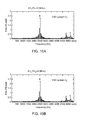
- CMV2 is of the form n ⁇ Fm where n is an integer and Fm is the fundamental component of the switching frequency of the machine bridge 3B.
- the amplitudes of common mode voltage CMV2 spectral components reduce as harmonic order n is increased.
- the fundamental voltage and frequency are lowest and common mode voltage CMV2 is greatest when the machine is at low speed.
- Common mode voltage CMV2 is dominant at low speeds and the spectrum analysis process must be able to rapidly detect the fundamental component or an integer or non-integer harmonic component of the switching frequency of the machine bridge 3B.
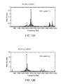
- Machine stator ground faults can occur in intermediate sites between ac line terminals and this reduces the fundamental voltage amplitude relative to the terminal voltages.
- the fundamental voltage and frequency are greatest and the common mode voltage CMV2 is lowest when the machine is at high speed.
- this component of common mode voltage is sufficient for the corresponding component of measured current to be detectable.
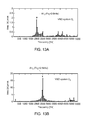
- Common mode voltage CMV1 of the supply bridge 3A is of the form m ⁇ Fs where m is an integer and Fs is the fundamental component of the switching frequency of the supply bridge.
- Common mode voltage CMV1 is typically variable over a small range in as much as dc link voltage and supply distribution voltage are well defined. The spectrum analysis process must be able to rapidly detect the fundamental component or an integer or non-integer harmonic component of the switching frequency of the supply bridge 3A.
- Common mode voltage CMV1 is summated with the dc link mid-point voltage and the summated voltages are impressed upon the supply ac lines 9.
- Common mode voltage CMV1 is of the form n ⁇ Fs.
- the amplitudes of common mode voltage CMV1 spectral components reduce as harmonic order n is increased.
- Common mode voltage CMV1 and the dc offset voltage vary over a small range and are both zero sequence voltage components. These summated zero sequence voltages cause corresponding zero sequence fault currents to flow in the supply ac lines 9 and in the EMC filter capacitor 6D of the respective ac line filter 6.
- the zero sequence fault current frequency spectrum that flows in the EMC filter capacitor 6D and the CBCT 16 at the input to the supply bridge 3A can be analysed in order to identify a type 2 ground fault.
- the presence of a type 1 ground fault at the supply ac lines 9 causes the fundamental component of the distribution voltage to be applied as a common mode voltage to the supply ac lines. It also causes a distribution frequency current to flow in the high resistance grounding resistor 8, in the supply ac lines 9 to the first filter reactor 6A and in the EMC filter capacitor 6D of the respective ac line filter 6.
- the fundamental component of the distribution voltage frequency (Fd) is normally 60 Hz and occasionally 50 Hz. Because the zero sequence fault currents have a low frequency, they are distributed primarily to the high resistance grounding resistor 8.
- the spectrum analysis process should be able to detect these fault currents in one cycle, e.g. 16.7 ms or 20 ms.
- a low pass filter may be used to isolate the distribution fundamental frequency component of current from the PWM current spectrum. Since voltages to ground throughout the power distribution system are now defined by the ground fault, and as a result of the PWM differential mode voltages between supply ac lines 9, zero sequence fault currents flow in the grounding resistor 8, the supply bridge ac lines to the first filter reactor 6A and in the EMC filter capacitor 6D of the respective ac line filter 6.
- Each controller 12 continuously carries out a spectrum analysis process that can be used for fault detection and fault location.
- Each controller 12 uses an appropriate digital signal processing (DSP) technique such as synchronous Discrete Fourier Transform (DFT) to derive a series of amplitudes of the frequency component within the zero sequence current frequency spectrum that correspond to the fundamental component of the switching frequency of the power converter 3.
- DFT digital signal processing
- each controller 12 derives a series of first amplitudes A1(Fc) where Fc is the fundamental component of the switching frequency of the power converter 3.
- Each controller 12 can additionally derive a series of second amplitudes A2(Fd) and third amplitudes A3(Fl) where Fl is the fundamental component of the machine stator (or load) voltage frequency.
- the first amplitudes A1(Fc) are compared against predetermined thresholds for fault detection and fault location. For example, A1(Fc) can be compared against a first threshold D1(Fc) for fault detection and a first threshold L1(Fc) for fault location. When the power distribution system 1" is operating normally, the first amplitudes A1(Fc) should be below the first fault detection threshold D1(Fc) because there is no ground fault in the power distribution system.
- the switching frequency process can also be initiated by other, conventional, ground fault detecting means.
- an unspecified ground fault can be detected based on:
- the first amplitudes A1(Fc) should be below the first fault location threshold L1(Fc). But if a ground fault is located in the particular VSD system, the first amplitudes A1(Fc) should exceed the first fault location threshold L1(Fc), i.e., A1(Fc)>L1(Fc). If a first amplitude A1(Fc) exceeds the first fault location threshold L1(Fc), a signal 20 is generated by the controller 12 and used to open a protective circuit breaker 21 for the associated VSD system 2 and/or to trip the VSD system.
- the second and third amplitudes A2(Fd) and A3(Fl) can optionally be used to determine the precise location of the ground fault within the faulty VSD system.
- the second and third amplitudes A2(Fd) and A3(Fl) can be compared against second and third fault location thresholds L2(Fd) and L3(Fl), respectively.
- ground fault protection equipment (not shown) is installed to protect the power distribution system 1" and this can be used to initiate circuit breaker/switchgear tripping if the location of the unspecified ground fault is not identified by the spectrum analysis process within a predetermined period of time, for example.
- Each controller 12 carries out a switching frequency process to improve the signal to noise ratio for the benefit of the spectrum analysis process, particularly for fault location.
- Corresponding first amplitudes A1 2 (Fc 2 ), A1 3 (Fc 3 ) and A1 4 (Fc 4 ) can be derived by the second, third and fourth controllers 12 2 , 12 3 and 12 4 for the fundamental component of the switching frequency of the second, third and fourth power converters 3 2 , 3 3 and 3 4 in a similar manner.
- the first, second, third and fourth controllers 12 1 -12 4 can each additionally derive a series of second amplitudes A2 1 (Fd 1 )-A2 4 (Fd 4 ) and third amplitudes A3 1 (Fl 1 )-A3 4 (Fl 4 ).
- the first amplitudes A1 1 (Fc 1 ), A1 2 (Fc 2 ), A1 3 (Fc 3 ) and A1 4 (Fc 4 ) can be compared against first fault detection thresholds D1 1 (Fc 1 ), D1 2 (Fc 2 ), D1 3 (Fc 3 ) and D1 4 (Fc 4 ) and first fault location thresholds L1 1 (Fc 1 ) L1 2 (Fc 2 ), L1 3 (Fc 3 ) and L1 4 (Fc 4 ), respectively, by the first, second, third and fourth controllers 12 1 -12 4 for fault detection and fault location purposes.
- the ground fault will propagate through the appropriate modes described above and should be detected because A1 1 (Fc 1 )>D1 1 (Fc 1 ) for the first VSD system 2 1 , Al2(Fc 2 )>D1 2 (Fc 2 ) for the second VSD system 2 2 , A1 3 (Fc 3 )>D1 3 (Fc 3 ) for the third VSD system 2 3 and A1 4 (Fc 4 )>D1 4 (Fc 4 ) for the fourth VSD system 2 4 .
- the detection of a ground fault at an unspecified location within the power distribution system 1" can be used to initiate a conventional ground fault protection process, for example.
- the first amplitudes A1 2 (Fc 2 ) should exceed the first fault location threshold L1 2 (Fc 2 ), i.e., A1 2 (Fc 2 )>L1 2 (Fc 2 ). But the first amplitudes for the first, third and fourth VSD systems 2 1 , 2 3 and 2 4 should not exceed the respective first fault location thresholds, i.e., A1 1 (Fc 1 ) ⁇ L1 1 (Fc 1 ), A1 3 (Fc 3 ) ⁇ L1 3 (Fc 3 ) and A1 4 (Fc 4 ) ⁇ L1 4 (Fc 4 ).
- a signal 20 is generated by the second controller 12 2 and used to open a protective circuit breaker 21 2 for the second VSD system and/or to trip the second VSD system.
- the second and third amplitudes A2 2 (Fd 2 ) and A3 2 (Fl 3 ) derived by the second controller 12 2 can optionally be used to determine the precise location of the ground fault within the second VSD system 2 2 .
- the derived amplitudes, fault detection thresholds and fault location thresholds are related to the pseudo-random series of switching frequencies.
- the switching frequency of the supply bridge 3A and the machine bridge 3B of each power converter 3 is continuously variable within a range of switching frequencies.
- the switching frequencies are controlled by the PWM generator 12A of each controller 12 and are provided as inputs to the spectrum analysis process that is applied by each controller to its respective power converter 3.
- the spectrum analysis process carried out by the first controller 12 1 will derive a series of first aggregated amplitudes A1 1 (Fc 1 ) for the first power converter 3 1 .
- the switching frequencies are a pseudo-random series and not a fixed value.
- Corresponding first aggregated amplitudes A1 2 (Fc 2 ), A1 3 (Fc 3 ) and A1 4 (Fc 4 ) can be derived by the second, third and fourth controllers 12 2 , 12 3 and 12 4 for the fundamental component of the switching frequency of the second, third and fourth power converters 3 2 , 3 3 and 3 4 in a similar manner.
- the first, second, third and fourth controllers 12 1 -12 4 can each additionally derive a series of second aggregated amplitudes A2 1 (Fd 1 )-A2 4 (Fd 4 ) and third aggregated amplitudes A3 1 (Fl 1 )-A3 4 (Fl 4 ).
- the first aggregated amplitudes A1 1 (Fc 1 ), A1 2 (Fc 2 ), A1 3 (Fc 3 ) and A1 4 (Fc 4 ) can be compared against first fault detection thresholds D1 1 (Fc 1 ), D1 2 (Fc 2 ), D1 3 (Fc 3 ) and D1 4 (Fc 4 ) and first fault location thresholds L1 1 (Fc 1 ) L1 2 (Fc 2 ), Lb(Fc 3 ) and L1 4 (Fc 4 ), respectively, by the first, second, third and fourth controllers 12 1 -12 4 for fault detection and fault location purposes.
- the ground fault will propagate through the appropriate modes described above and should be detected because A1 1 (Fc 1 )>D1 1 (Fc 1 ) for the first VSD system 2 1 , A1 2 (Fc 2 )>D1 2 (Fc 2 ) for the second VSD system 2 2 , A1 3 (Fc 3 )>D1 3 (Fc 3 ) for the third VSD system 2 3 and A1 4 (Fc 4 )>D1 4 (Fc 4 ) for the fourth VSD system 2 4 .
- the detection of a ground fault at an unspecified location within the power distribution system 1" can be used to initiate a conventional ground fault protection process, for example.
- the first aggregated amplitudes A1 2 (Fc 2 ) should exceed the first fault location threshold L1 2 (Fc 2 ), i.e., A1 2 (Fc 2 )>L1 2 (Fc 2 ). But the first aggregate amplitudes for the first, third and fourth VSD systems 2 1 , 2 3 and 2 4 should not exceed the first fault location thresholds, i.e., A1 1 (Fc 1 ) ⁇ L1 1 (Fc 1 ), A1 3 (Fc 3 ) ⁇ L1 3 (Fc 3 ) and A1 4 (Fc 4 ) ⁇ L1 4 (Fc 4 ).
- a signal 20 is generated by the second controller 12 2 and used to open a protective circuit breaker 21 2 for the second VSD system and/or to trip the second VSD system.
- the second and third amplitudes A2 2 (Fd 2 ) and A3 2 (Fl 2 ) derived by the second controller 12 2 can optionally be used to determine the precise location of the ground fault within the second VSD system 2 2 .
- the switching frequencies are controlled by the PWM generator 12A of each controller 12 and are provided as inputs to the spectrum analysis process that is applied by each controller to its respective power converter 3.
- the third switching frequency process can be initiated by any suitable means. But in one arrangement the switching frequency process is initiated by the spectrum analysis process that is carried out by the first, second, third and fourth controllers 12 1 -12 4 .
- the first controller 12 1 will derive a series of first amplitudes A1 1 (Fc 1 ) for the fundamental component of the nominal switching frequency of the first power converter 3 1 .
- Corresponding first amplitudes A1 2 (Fc 2 ), Al 3 (Fc 3 ) and A1 4 (Fc 4 ) can be derived by the second, third and fourth controllers 12 2 , 12 3 and 12 4 for the fundamental component of the nominal switching frequency of the second, third and fourth power converters 3 2 , 3 3 and 3 4 in a similar manner.
- the first amplitudes A1 1 (Fc 1 ), A1 2 (Fc 2 ), Al 3 (Fc 3 ) and A1 4 (Fc 4 ) can be compared against first fault detection thresholds D1 1 (Fc 1 ), D1 2 (Fc 2 ), D1 3 (Fc 3 ) and D1 4 (Fc 4 ), respectively, by the first, second, third and fourth controllers 12 1 -12 4 for fault detection purposes.
- the ground fault will propagate through the appropriate modes described above and should be detected because A1 1 (Fc 1 )>D1 1 (Fc 1 ) for the first VSD system 2 1 , A1 2 (Fc 2 )>D1 2 (Fc 2 ) for the second VSD system 2 2 , A1 3 (Fc 3 )>D1 3 (Fc 3 ) for the third VSD system 2 3 and A1 4 (Fc 4 )>D1 4 (Fc 4 ) for the fourth VSD system 2 4 .
- the detection of a ground fault at an unspecified location within the power distribution system 1" can be used to initiate the switching frequency process in each controller 12 1 -12 4 .
- the first amplitudes A1 1 (Fc 1 ), A1 2 (Fc 2 ), Al 3 (Fc 3 ) and A1 4 (Fc 4 ) can be compared against first fault location thresholds L1 1 (Fc 1 ) L1 2 (Fc 2 ), L1 3 (Fc 3 ) and L1 4 (Fc 4 ), respectively, by the first, second, third and fourth controllers 12 1 -12 4 for fault location even before the third switching frequency process is initiated.
- a first amplitude might exceed the first fault location threshold at the fundamental component of the nominal switching frequency, i.e., A1 3 (Fc 3 )>L1 3 (Fc 3 ) before the switching frequency process begins.
- a signal 20 is generated by the third controller 12 3 and used to open a protective circuit breaker 21 3 for the third VSD system 3 2 and/or to trip the third VSD system without the need to initiate the switching frequency process.
- the third switching frequency process When the third switching frequency process is initiated in a particular controller 12, it will wait for a predetermined period of time before applying a switching frequency operation to its associated power converter 3.
- a predetermined period of time In this example, it is assumed that the switching frequency operation is applied simultaneously to both the supply bridge 3A 1 -3A 4 and the machine bridge 3B 1 -3B 4 of each power converter 3 1 -3 4 .
- the predetermined period of time for each controller 12 1 -12 4 is selected such that the switching frequency operations are applied to the VSD systems 2 1 -2 4 of the power distribution system 1" in a non-overlapping manner.
- the supply bridge 3A and the machine bridge 3B When a switching frequency operation is applied to a particular power converter 3, the supply bridge 3A and the machine bridge 3B will be operated at a displaced switching frequency (e.g., 2.0 kHz) for a predetermined period of time before reverting back to the nominal switching frequency of 2.5 kHz.
- the switching frequency of the supply bridge 3A and the machine bridge 3B is varied between the nominal switching frequency and the displaced switching frequency by the PWM generator 12A of each controller 12.
- Figures 8A and 8B show how the switching frequency operations are applied sequentially to each of the four power converters 3 1 -3 4 . It is assumed that an unspecified ground fault is detected at time t0 and that the switching frequency process is initiated simultaneously at t0 in all controllers 12 1 -12 4 . The first controller 12 1 waits for a predetermined period of time T1 before applying the switching frequency operation to the first power converter 3 1 .
- the second controller 12 2 waits for a predetermined period of time T3 before applying the switching frequency operation to the second power converter 3 2 .
- T3 T2+ ⁇ T where ⁇ T is a predetermined delay that provides a gap between the sequential switching frequency operations.
- the third controller 12 3 waits for a predetermined period of time T4 before applying the switching frequency operation to the third power converter 3 3 .
- T4 (T3+T2)+ ⁇ T.
- the fourth controller 12 4 waits for a predetermined period of time T5 before applying the switching frequency operation to the fourth power converter 3 4 .
- T5 (T4+T2)+ ⁇ T.
- a fault location determination is made by the third controller 12 3 at time t1.
- the switching frequency operation is applied to the third power converter 3 3 which will operate at the displaced switching frequency for a predetermined period of time T2.
- Figures 12A and 12B show the zero sequence current frequency spectra for the first VSD system 2 1 and the third VSD system 2 3 , respectively, for a time window during the predetermined period of time T2 when the switching frequency operation is applied to the third power converter 3 3 .
- a signal 20 is generated by the third controller 12 3 and used to open a protective circuit breaker 21 3 for the third VSD system 2 3 and/or to trip the third VSD system.
- Each controller 12 1 -12 4 can additionally derive second amplitudes A2 1 (Fd 1 )-A2 4 (Fd 4 ) and third amplitudes A3 1 (Fl 1 )-A3 4 (Fl 4 ).
- the second and third amplitudes A2 3 (Fd 3 ) and A3 3 (Fl 3 ) derived by the third controller 12 3 can optionally be used to determine the precise location of the ground fault within the third VSD system 2 3 .
- the third power converter 3 3 will revert back to being operated at the nominal switching frequency for the remainder of the switching frequency process.
- Switching frequency operations will be applied to the first, second and fourth power converter 3 1 , 3 2 and 3 4 in the same manner but the first amplitudes should not exceed the respective first fault location threshold at either the fundamental component of the nominal switching frequency or the displaced switching frequency.
- Figures 13A and 13B show the zero sequence current frequency spectra for the first VSD system 2 1 and the third VSD system 2 3 , respectively, for a time window during the period of time T2 when the switching frequency operation is applied to the first power converter 3 1 .
- Figures 10A, 10B , 11A, 11B , 12A, 12B , 13A and 13B show the amplitudes for all zero sequence current frequencies up to 5.5 kHz. But in practice the DSP technique will isolate just the one or more desired frequency components from the zero sequence current frequency spectra.
- the switching frequency operations are applied sequentially to each of the four power converters 3 1 -3 4 without a fault location determination being made.
- the switching frequency process is therefore repeated with the first controller 12 1 applying the switching frequency operation to the first power converter 3 1 for a second time at time t2.
- the switching frequency operation is then applied to sequentially to the second, third and fourth power converters 3 2 , 3 3 and 3 4 as described above.
- Figure 8B shows a fault location determination being made by the first controller 12 1 at time t3.
- Figure 8A shows how a ground fault might be located in the third VSD system 2 3 and that this is detected by the third controller 12 3 at time t1. It will be noted that even when a ground fault is located in the third VSD system 2 3 by the third controller 12 3 , the switching frequency operation will still be applied to the fourth power converter 3 4 by the fourth controller 12 4 because the controllers are operated independently. Similarly, Figure 8B shows how a ground fault might be located in the first VSD system 2 1 and that this is detected by the first controller 12 1 at time t3 when the switching frequency process is repeated.
- Step 1 A ground fault occurs that affects all VSD systems.
- Step 2 The ground fault is detected by the controller at t0
- Step 3 The zero sequence currents for the associated power converter system are measured or derived, e.g., using a CBCT or CT.
- Step 4 The controller applies a spectrum analysis to the zero sequence currents and derives a series of amplitudes A1(F1).
- Step 5 After a predetermined time delay, the controller applies a frequency switching operation to the respective VSD system where the switching frequency of the supply bridge and the machine bridge is changed from the nominal switching frequency to the displaced switching frequency for a predetermined period of time before reverting back to the nominal switching frequency.
- Step 6 The controller compares the derived amplitudes A1(F1) against the corresponding fault location threshold L1(F1), which can be preset or derived using power converter system parameters.
- Step 7 If a derived amplitude A1(F1) is greater than the corresponding fault location threshold L1(F1) the VSD system is tripped.
- Step 8 A signal that is indicative that a ground fault is present in the VSD system is provided to trip the associated protective circuit breaker/switchgear and isolate the VSD system from the distribution bus 5. This signal is preferably generated before the circuit breaker/switchgear is tripped by a conventional ground fault protective process that is effective within the switchboard that incorporates the associated circuit breaker/switchgear for the VSD system (Step 9).
Abstract
Description
- The present invention relates to ground fault protection of power distribution systems, particularly those systems in which a plurality of power converter systems are interconnected by a point of common coupling without the use of isolating transformers or any form of low resistance grounding network. The present invention addresses the difficulty in achieving ground fault discrimination in such "floating" or high resistance grounded systems.
- It is known that when a ground fault is present in a transformerless, high resistance grounded, power distribution system that interconnects a plurality of power converter systems (e.g., variable speed drive (VSD) systems), the voltages to ground in all parts of the system are affected by the presence of the ground fault, wherever the ground fault is located. Consequently, there is a requirement to precisely identify the location of such a ground fault, take protective actions to isolate that fault as soon as possible, and for this to be achieved without the operation of non-faulted equipment being disturbed. Non-faulted equipment that is electrically connected to such a power distribution system is expected to operate briefly under the associated additional voltage stress while these protective actions are being carried out.
- An example of a conventional transformerless, high resistance grounded, power distribution system is shown in
Figure 1 . Thepower distribution system 1 provides power to four VSD systems 21-24. EachVSD system 2 is electrically connected to adistribution bus 5 that defines a point of common coupling and includes apower converter 3 of the back to back pulse width modulation (PWM) voltage source inverter (VSI) type and anac line filter 6. EachVSD system 2 is used to interface an electrical machine 7 (e.g., a motor) to thedistribution bus 5. Thepower distribution system 1 shown inFigure 1 is for a marine vessel (e.g., a ship, drilling rig or any other surface-going vessel or platform or submersible (submarine) vessel) but it will be understood that similar power distribution systems can be used for other applications. - Each
power converter 3 includes asupply bridge 3A having ac terminals electrically connected to adistribution bus 5 and amachine bridge 3B electrically connected to theelectrical machine 7. Themachine bridge 3B will often be directly connected to theelectrical machine 7, but it can also be indirectly connected by a filter, e.g., a sine wave filter. The dc output of eachsupply bridge 3A is electrically connected to the dc input of themachine bridge 3B by adc link 3C. Thesupply bridge 3A andmachine bridge 3B are active rectifier/inverters with a plurality of semiconductor switching devices controlled using a PWM strategy. Thesupply bridge 3A of eachpower converter 3 is electrically connected to thedistribution bus 5 by theac line filter 6. - Each
ac line filter 6 includes afirst filter reactor 6A, asecond filter reactor 6B and anadditional filter component 6C. Theac line filter 6 also includes afilter capacitor 6D that is connected to ground. As used herein, thesubscripts 1 to 4 are used to indicate components or operating parameters of the first, second, third and fourth VSD systems 21-24, respectively. This includes indicating components or operating parameters of thepower converter 3 and theac line filter 6. For example, thesupply bridge 3A1 is the supply bridge of thefirst power converter 31 which forms part of thefirst VSD system 21. - In normal operation, each
supply bridge 3A will operate as an active rectifier to supply power to thedc link 3C and eachmachine bridge 3B will operate as an inverter to supply power to therespective machine 7. But it will be readily appreciated that in some situations, the direction of power flow may be reversed, e.g., if aparticular machine 7 is operated in a generating mode or experiencing regenerative braking where power is supplied to thedistribution bus 5. In this case, themachine bridge 3B of the associatedVSD system 2 will operate as an active rectifier to supply power from themachine 7 to thedc link 3C and thesupply bridge 3A will operate as an inverter to supply power to thedistribution bus 5. - Generators 4 (e.g., diesel generators) supply power to the
distribution bus 5. Thepower distribution system 1 will typically include a first bus section and a second bus section that are interconnected by a bus tie. Some power distribution systems use a plurality of bus sections interconnected by a plurality of bus ties to improve power availability. - As noted above, the direction of power flow is generally from the
generators 4 to the machines 71-74 through thedistribution bus 5, the ac line filters 61-64 and the respective power converters 31-34. The normal working mean voltage to ground throughout thepower distribution system 1 is defined by at least one highresistance grounding resistor 8 whereas the non zero frequency symmetry of the normal working ac phase voltage relative to ground is defined by the capacitance to ground of the ac line filters 61-64. During ground faults, the voltages to ground throughout thepower distribution system 1 experience perturbations from their normal working conditions and these perturbations are dependent on the nature and location of the ground fault. These ground faults also cause abnormal zero sequence currents to flow throughout thepower distribution system 1. As used herein, the term 'zero sequence current' refers to the residual component of current after summation of the individual ac line currents of a polyphase system. It will be readily appreciated that the zero sequence currents do not experience phase rotation. Since such a power distribution system is typically extensive and includes a number of items of equipment that routinely generate common mode voltages and/or have deliberate or parasitic capacitance to ground, it is generally the case that a wide spectrum of zero sequence currents flow throughout the system when in normal operation, albeit of controlled magnitude. - Three different types of ground fault are identified in
Figure 1 and are labelled 'type 1', 'type 2' and 'type 3', respectively. Atype 1 ground fault is a ground fault in one of the supply ac lines 91-94 (i.e., the ac lines between thedistribution bus 5 and therespective supply bridge 3A1-3A4, including the ac line filter 61-64), atype 2 ground fault is a ground fault in thedc link 3C of the power converter and atype 3 ground fault is a ground fault in one of the machine ac lines 101-104 (i.e., the ac lines between themachine bridge 3B and the respective machine 71-74). If each VSD drive includes a filter, e.g., a sine wave filter (not shown), between the machine bridge and the machine, atype 3 ground fault will typically have similar characteristics to atype 1 ground fault. - A number of techniques have been developed to allow ground faults to be detected and zero sequence current detection means are commonly employed for this purpose. Zero sequence currents are typically detected by core balance current transformers (CBCTs) and simplistic detectors. But these devices have only a limited ability to discriminate between zero sequence fault currents and the zero sequence currents associated with normal operation. This discrimination can be made ineffective when zero sequence fault currents flow in healthy or non-faulted equipment as a result of the above perturbations in voltages to ground when a ground fault is present, and in the worst case can result in the unnecessary tripping of non-faulted equipment.
- In another well-known ground fault detection system based upon the use of current transformers, a dedicated pulse generator injects a known spectrum of zero sequence voltages into the distribution bus at a high level in the power distribution system. The current transformers and a specialised detector are used to identify the abnormal zero sequence currents that are associated with a ground fault in a particular branch of the power distribution system. This method is calibrated to measure branch insulation resistance, despite there potentially being a large distributed capacitance to ground. In practice, this method has inadequate signal to noise ratio to operate effectively in systems that employ back to back PWM VSIs with significant supply side capacitive ac line filters.
- It is common practice to use voltage detectors to identify the presence of the abnormal common mode voltages that are associated with ground faults when the VSD systems benefit from an isolating transformer power supply. Such VSD systems are similar to the VSD systems 21-24 shown in
Figure 1 but the coupling between thedistribution bus 5 and theac line filter 6 is by means of a transformer, which provides galvanic isolation. The common mode voltages CMV1 and CMV2 may be detected when atype 1,type 2, ortype 3 ground fault is present. For example, when a supply isolation transformer is used, this provides common mode voltage isolation between the distribution bus and the associated VSD system and it is common practice to sense the voltage between the mid-point of thedc link 3C and ground in order to locate a ground fault. This also allows the ground fault type to be discriminated as follows: - a
type 1 ground fault causes the dc mid-point voltage to be offset from its normal condition by the distribution phase voltage - a
type 2 ground fault causes the dc mid-point voltage to be offset from its normal condition by Vdc/2 - a
type 3 ground fault causes the dc mid-point voltage to be offset from its normal condition by the machine phase voltage - The voltage offsets that are experienced in the cases of
type 2 andtype 3 ground faults include all spectral components of the respective phase voltage, i.e., a classical PWM spectrum, and it is known for the detection of these voltages to be performed by techniques ranging from the use of passively filtered detectors to sophisticated signature-based detectors. When signature-based detectors are used, these are based upon the principle that the detector will have an inbuilt knowledge of the PWM spectra of the associated power converter. - However, when a supply isolation transformer is not provided, as in the case for the
power distribution system 1 shown inFigure 1 , the common mode voltages CMV1 and CMV2 may be detected in all of the VSD systems 21-24 that are electrically connected to the point of common coupling provided by thedistribution bus 5 when a ground fault oftype 1,type 2, ortype 3 is present in just one of the VSD systems. Such power distribution systems are commonly known as transformerless systems and are known not to be capable of providing ground fault protection discrimination when the above types of common mode voltage detection are employed. - The voltage sensing method has also been applied to ac lines by detecting the voltage between an artificial neutral point (the mid-point of a star (wye) connected resistive network) and ground. This form of voltage sensing is also compromised when a supply isolation transformer is not provided.
- The above-described method of detecting zero sequence currents using CBCTs and RMS detectors has been enhanced to allow the spectral content of the zero sequence component of ac line currents to be resolved in order to determine whether normal or ground faulted conditions are present. However, when a supply isolation transformer is not provided, the common mode voltages CMV1 and CMV2, in being impressed upon all parts of the power distribution system, cause zero sequence currents to be detected in all of the VSD systems that are electrically connected to the point of common coupling provided by the distribution bus when a ground fault of
type 1,type 2, ortype 3 is present in just one of the VSD systems. The propagation of ground fault-related zero sequence currents into the ac line filters of otherwise healthy or non-faulted VSD systems is governed by the interconnecting zero sequence impedances and the nature of the ac line filters - it generally being the case that these ac line filters have significant capacitance to ground in order to comply with Electromagnetic Compatibility (EMC) legislation. In practice, when a single VSD system experiences atype 2 ortype 3 ground fault, all of the VSD systems experience similar zero sequence components of ac line currents and such a detection system is not capable of providing ground fault protection discrimination. When a single VSD system experiences atype 1 ground fault, if the grounding resistance and EMC capacitance are suitably designed, it can be possible for a detection system to be capable of providing ground fault protection discrimination. It is known that the failure to provide this discrimination or ground fault location can result in the tripping of all VSD systems that are electrically connected to the point of common coupling even though some of the VSD systems are healthy. - Similar methods have been applied to ground fault detection in power distribution systems with multiple VSD systems having a point of common coupling that is a dc distribution bus as opposed to the ac distribution bus shown in
Figure 1 . - Signature-based ground fault detection methods have become increasingly sophisticated yet fail to provide reliable ground fault discrimination in power distribution systems that employ a plurality of identical or similar VSD systems. It has proven to be difficult to provide the required detection dependability and response time for all operating conditions and fault conditions.
- The propagation of zero sequence currents within a representative power distribution system 1' will now be described with reference to
Figures 2 to 4 . - The representative power distribution system 1' of
Figure 2 is similar to thepower distribution system 1 shown inFigure 1 and like components have been given the same reference numeral. The power distribution system 1' includes adistribution bus 5, which defines a point of common coupling between interconnected branches, and conventional circuit breaker/switchgear arrangements to allow connection of agenerator 4, afirst VSD system 21 and asecond VSD system 22 to the distribution bus. Thefirst VSD system 21 includes afirst power converter 31 of the back to back PWM VSI type and a firstac line filter 61 and is used to interface a first electrical machine 71 (e.g., a motor) to thedistribution bus 5. Thesecond VSD system 22 includes asecond power converter 32 of the back to back PWM VSI type and a secondac line filter 62 and is used to interface a second electrical machine 72 (e.g. a motor) to thedistribution bus 5. - As is the case for all back to back PWM VSI type power converters, irrespective of voltage and power ratings, the first common mode voltage CMV1 of the
supply bridge 3A1 is continuously applied between the mid-point of thedc link 3C1 and the neutral point of theac lines 91 of the supply bridge, and the common mode voltage CMV2 of themachine bridge 3B1 is continuously applied between the neutral point of themachine ac lines 101 and the mid-point of thedc link 3C1. It therefore follows that the sum of common mode voltages CMV1 and CMV2 is continuously applied between the neutral point of thesupply ac lines 91 and the neutral point of the machine ac lines 101. The magnitudes of the individual spectral components of the common mode voltages CMV1 and CMV2 are substantially pro rota with the dc link voltage and vary additionally according to the modulation depth of thesupply bridge 3A1 and themachine bridge 3B1 respectively. - It will be readily appreciated that the fundamental component of the PWM switching frequency that is applicable to the
supply bridge 3A1 and themachine bridge 3B1 is present in the common mode voltages CMV1 and CMV2, respectively, at all practically useful modulation depths. The voltage to ground at any point in the representative power distribution system 1' is governed by the relative levels of impedances to ground throughout the system - these impedances generally being capacitive, and ground faults typically having a dominantly low resistive impedance to ground and therefore defining the voltages to ground elsewhere in the system. These voltages to ground and impedances to ground define the currents that flow to ground, i.e., the zero sequence currents. It therefore follows that zero sequence currents are a maximum when a ground fault is present. - Five significant modes of propagation of zero sequence fault currents within the power distribution system 1' exist when a
type 3 ground fault is present. The current circulation paths of the first three modes are shown inFigure 2 and the current circulation paths of all five modes are shown in single phase equivalent circuit form inFigure 3 . - It is assumed that a
type 3 ground fault is present within thefirst VSD system 21. As a result of the presence of the ground fault on one of themachine ac lines 101, the common mode voltage CMV2 of themachine bridge 3B1 is applied to thedc link 3C1 and the common mode voltage CMV1 of thesupply bridge 3A1 is then superimposed upon CMV2 and the sum of CMV1 and CMV2 is impressed upon the supply ac lines 91. TheEMC filter capacitor 6D1 is connected to ground, hence a circulating current path is present and this is the first mode (labelled 'M1') of propagation of zero sequence fault currents. The magnitude of zero sequence fault currents is defined by common mode voltages CMV1 and CMV2, the zero sequence impedance of thesecond filter reactor 6B1, the impedance of theEMC filter capacitor 6D1, and stray interconnecting impedances (not shown). These stray impedances are minimised by design in the interest of EMC and will be described in more detail below with reference to the third and fourth modes. - The
type 3 ground fault also causes the common mode voltage that is applied to theEMC filter capacitor 6D1 to be increased. This voltage is also generally applied to equipment that is electrically connected to the point of common coupling but its amplitude is progressively and only slightly reduced as it propagates through the zero sequence impedance of thefirst filter reactor 6A1, the zero sequence impedances of thedistribution bus 5, the zero sequence impedance of thefirst filter reactor 6A2 of the secondac line filter 62, and then to theEMC filter capacitor 6D2 of the second ac line filter. The zero sequence fault currents then return to the site of the ground fault at the machine ac lines 101. This propagation is the second mode of propagation (labelled 'M2'). The spectra of zero sequence fault currents that flow in theEMC filter capacitor 6D1, thefirst filter reactor 6A1, thefirst filter reactor 6A2 and theEMC filter capacitor 6D2 are closely related in as much as they share the same source of common mode voltage, i.e., CMV1 and CMV2, and the degree of attenuation in thefirst filter reactor 6A2 and theEMC filter capacitor 6D2 of the secondac line filter 62, progressively increases in significance as harmonic order increases. It will be readily appreciated that the zero sequence fault currents that flow in theEMC filter capacitor 6D1, thefirst filter reactor 6A1, thefirst filter reactor 6A2 and theEMC filter capacitor 6D2 are phase shifted relative to one another according to their impedances. - The
supply bridge 3A2 and themachine bridge 3B2 of thesecond VSD system 22 have respective common mode voltages CMV3 and CMV4 that are of similar form to the common mode voltages CMV1 and CMV2. In practice, they may be identical to the common mode voltages CMV1 and CMV2 when similar operating conditions are experienced by the first andsecond VSD systems electrical machine 72 has a significant distributedcapacitance 112 to ground and this provides a path between themachine ac lines 102 and local ground (i.e., the local point of connection in the ground network). The form of the third mode M3 is similar to that of the first mode M1 and the zero sequence fault currents are of a similar nature to those that flow in the first mode. In practice, the impedance of the distributedcapacitance 112 to ground is generally greater than the impedance of the ground faults and the magnitude of current in the third mode M3 that flows in theEMC filter capacitor 6D2 is generally less than the zero sequence fault currents of the first and second modes M1, M2. The zero sequence fault currents that flow in the third mode M3 commonly have similar frequency characteristics to those of the first and second modes M1, M2. - With reference to
Figure 3 , common mode voltages CMV3 and CMV4 also cause a fourth mode (labelled 'M4') of propagation of zero sequence fault currents. The form of the fourth mode M4 is similar to that of the second mode M2 and the zero sequence fault currents are of a similar nature to those that flow in the second mode. In practice, the impedance of the distributedcapacitance 112 to ground is generally greater than the impedance of the ground faults and the magnitude of zero sequence fault currents in the fourth mode M4 that flows in theEMC filter capacitor 6D1 of the firstac line filter 61 is generally less than the zero sequence fault currents of the first, second and third modes M1-M3. The zero sequence fault currents that flow in the fourth mode M4 commonly have similar frequency characteristics to those of the first and second modes M1, M2. - A fifth mode (labelled 'M5') also exists encompassing all four common mode voltages CMV1, CMV2, CMV3 and CMV4 and with currents flowing between the ground fault and distributed
capacitance 112 to ground. The magnitude of the zero sequence fault currents that flow in the fifth mode M5 are generally less than the zero sequence fault currents of the first, second, third and fourth modes M1-M4 and comprises the frequencies associated with the summation of all four common mode voltages. In general terms the magnitude of the various sequence fault current propagation modes is M1>M2>M3>M4>M5. -
Figure 3 also shows the current circulation paths through the highresistance grounding resistor 8. The high impedance of this resistor causes currents that pass through this resistor to have a relatively small magnitude. The modes that flow in the highresistance grounding resistor 8 are labelled 'Ma' and 'Mb'. - When a
type 2 ground fault is present, a sixth mode of propagation of zero sequence fault currents comprising two circulating current paths exists and these are labelled 'M6a' and 'M6b' in single phase equivalent circuit form inFigure 4 . - The first circulating current path of the sixth mode M6a is similar to the first mode M1 of propagation of zero sequence fault currents, the difference being that the common mode voltage CMV2 is no longer summated with the common mode voltage CMV1 because the ground reference point is now in either the positive or negative terminal of the
dc link 3C1 according to the location of the ground fault. This ground reference point is also applicable to the common mode voltage CMV2 of themachine bridge 3B1 and this causes the second circulating current path of the sixth mode M6b to exist. As is the case for the relationship between the first and second modes of propagation of zero sequence fault currents, the first circulating current path of the sixth mode of propagation of zero sequence fault currents is associated with a seventh mode of propagation of zero sequence fault currents (labelled 'M7'). The seventh mode M7 is similar to the second mode M2 but in this case the mode of propagation of zero sequence fault currents is not excited by the common mode voltage CMV2 of themachine bridge 3B1. - Eighth and ninth modes of propagation of zero sequence fault currents (labelled 'M8' and 'M9') are equivalent to the third and fourth modes M3, M4. A tenth mode of propagation of zero sequence fault currents (labelled 'M10') is similar to the fifth mode M5. However, it will be readily appreciated that the eighth, ninth and tenth modes are not exited by the common mode voltage CMV2 of the
machine bridge 3B1. - A single phase equivalent circuit showing the modes of propagation during a
type 1 ground fault has not been included because the propagation between VSD systems is greatly reduced as a result of the voltage to ground of the distribution bus being set by the ground fault. - When a
type 1 ground fault is present, the propagation of zero sequence fault currents in thedistribution bus 5 is dominated by a first current component that is defined by the fundamental component of the ac power distribution phase voltage and the ohmic value of the highresistance grounding resistor 8. The second mode M2 of propagation of zero sequence fault currents is also effective and these respective currents are superimposed upon the first current component. When a conventional high resistance ground current detection process is employed, i.e., a detection process that is generally responsive to the fundamental component of the distribution voltage frequency, this detection process is generally rendered non-responsive to the circulating currents that are defined by the second mode M2 of propagation of zero sequence fault currents as a result of careful selection of the highresistance grounding resistor 8 and the capacitance to ground of theEMC filter capacitor 6D of theac line filter 6. The EMC filter capacitance is defined with the specific objective of reducing the high frequency spectral content of common mode voltage that is experienced throughout thedistribution bus 5. - Practical power distribution systems typically have more than one generator and more than two VSD systems. The VSD systems are generally identical or at least have identical modular power electronics and PWM control strategies for reasons of system simplification, economy and reduced spares holding. The above description of the nature of the zero sequence fault current propagation modes is adequate for the proper understanding of the present invention, but it will be readily understood that many more propagation modes exist in practice.
- The present invention provides a ground fault protection method for a power distribution system comprising a plurality of power converter systems electrically connected to a point of common coupling (e.g., a distribution bus), each power converter system including a power converter with a plurality of semiconductor switching devices controlled using a pulse width modulation (PWM) strategy with a switching frequency, the method comprising applying a spectrum analysis process to each power converter system that uses measured or derived zero sequence currents associated with the respective power converter system to determine the location of a ground fault within the power distribution system, and a switching frequency process where the switching frequency of the power converter of at least one of the power converter systems is different from the switching frequency of the power converter of at least another one of the power converter systems (i.e., so that the power converters of at least two of the plurality of power converter systems have a different switching frequency) during at least part of the time that the spectrum analysis process is applied.
- The present invention further provides a power distribution system comprising a plurality of power converter systems electrically connected to a point of common coupling, each power converter system including a power converter with a plurality of semiconductor switching devices controlled using a PWM strategy with a switching frequency, wherein the power distribution system further includes a controller for each power converter system, each controller being adapted to apply a spectrum analysis process to the respective power converter system that uses measured or derived zero sequence currents associated with the respective power converter system to determine the location of a ground fault within the power distribution system, and each controller being adapted to apply a switching frequency process where the switching frequency of the power converter of at least one of the power converter systems is different from the switching frequency of the power converter of at least another one of the power converter systems during at least part of the time that the spectrum analysis process is applied.
- The spectrum analysis process can also be used to initially detect the presence of a ground fault at an unspecified location within the power distribution system.
- The spectrum analysis process applied to each power converter system can comprise the steps of:
- measuring or deriving zero sequence currents associated with the respective power converter system;
- performing spectrum analysis on the zero sequence currents and deriving the amplitude of a frequency component within the zero sequence current frequency spectrum; and
- comparing the derived amplitude against a threshold or at least one stored amplitude (e.g., an amplitude of the same frequency component previously derived from the spectrum analysis process and stored in a suitable memory).
- The steps will typically be repeated such that the spectrum analysis process derives a series of amplitudes while it is applied to each power converter system.
- The frequency component within the zero sequence current frequency spectrum will normally be the fundamental component or an integer or non-integer harmonic component of the switching frequency of the power converter of the respective power converter system. For example, if a power converter has a switching frequency (or carrier frequency) of 2.5 kHz, the frequency component will normally be 2.5 kHz or an integer or non-integer harmonic component of 2.5 kHz. The amplitude of two or more different frequency components can be derived simultaneously within the zero sequence current frequency spectrum and each amplitude can be compared against a respective threshold or stored amplitude(s). Additional frequency components within the zero sequence current frequency spectrum can be the fundamental component or an integer or non-integer harmonic component of the distribution voltage frequency (e.g., 50 or 60 Hz for a conventional power distribution system) and the fundamental component or an integer or non-integer harmonic component of the machine stator or load voltage frequency. The additional frequency components can optionally be used to determine the location of the ground fault within the respective power converter system, i.e., to determine if the ground fault is a
type 1,type 2 ortype 3 ground fault where appropriate. - The amplitude of the frequency component(s) within the zero sequence current frequency spectrum can be derived using any suitable and time-efficient digital signal processing (DSP) technique including inter alia synchronous discrete Fourier transform (DFT), Goertzel algorithm (or filter) and heterodyne with frequency. The spectrum analysis process is used to reliably and rapidly detect the amplitude of the frequency component(s) within the complete spectrum of zero sequence currents. Each frequency component is known and can be provided as an input to the spectrum analysis process. For example, the controllers will normally be provided with data that includes inter alia the prevailing PWM switching frequency, the distribution voltage frequency and the machine stator or load voltage frequency to allow the controllers to carry out routine operational control of the power converters. The sampling rate of a synchronous DFT is preferably synchronised to the PWM generator for the respective power converter. The Goertzel filter is a simplified and computationally more efficient version of the DFT that is adapted to identify a single frequency and has a similar function to the DFT. With heterodyne technique the heterodyne frequency is identical to the required frequency component and the method is concluded by detecting that the difference frequency output is zero. Some DSP techniques will be followed by amplitude detection.
- If a derived amplitude exceeds a fault detection threshold, the spectrum analysis process can generate a signal indicative of a ground fault being present at an unspecified location within the power distribution system (a 'fault detection signal'). If an amplitude exceeds a fault location threshold, the spectrum analysis process can generate a signal indicative of a ground fault being present within the respective power converter system (a 'fault location signal'). A fault detection signal or a fault location signal can also be generated based on the comparison between a derived amplitude and one or more stored amplitudes, e.g., if a derived amplitude exceeds a stored amplitude optionally by a predetermined margin. Such a comparison can identify variations in the amplitudes at the frequency component that can indicate the presence of a ground fault at an unspecified location within the power distribution system or within the respective power converter system.
- The simultaneously-derived amplitudes within the zero sequence current frequency spectrum can be identified generally as A1(F1), A2(F2)-An(Fn) where A1 is the amplitude at a first frequency component F1, A2 is the amplitude at a second frequency component F2 and An is the amplitude at an nth frequency component Fn. Thresholds can be identified generally as T1(F1), T1(F1)-Tn(Fn) where T1 is the threshold at the first frequency component F1, T2 is the threshold at the second frequency component F2 and Tn is the threshold at the nth frequency component Fn. It can therefore be understood that each amplitude and each threshold are a function of the corresponding frequency component. The simultaneously-derived amplitudes A1(F1)-An(Fn) can be compared against a respective threshold (e.g., a fault detection threshold D1(F1)-Dn(Fn) and/or a fault location threshold L1(F1)-Ln(Fn) for the particular frequency component F1-Fn).
- The spectrum analysis process can be continuously applied to each power converter system by the respective controller.
- Each threshold can be preset for the particular power converter system or derived using one of more of the following power converter system parameters as appropriate:
- supply ac line voltage
- dc link voltage
- load ac line voltage
- supply ac line frequency
- load ac line frequency
- PWM control strategy parameters
- impedance data for any associated ac line filter
- impedance data for any system zero sequence stray and/or parasitic components
- It follows that each threshold can be a fixed (or preset) threshold or a variable threshold, e.g., it can vary in response to changes in the power converter system parameters. Each threshold may be derived using a look-up table which may be based on data obtained during system commissioning or during normal operation. One or more of the power converter system parameters can be used as a pointer to the look-up table, which is effectively a series of preset thresholds.
- If a fault location signal is generated by the spectrum analysis process it can be used to open a protective circuit breaker/switchgear for the respective power converter system to isolate it from the point of common coupling (e.g., a distribution bus to which the power converter systems are electrically connected) and/or trip the power converter system. An objective of the present invention is to maximise power distribution system and associated equipment availability. This involves utilising the method to avoid having to open protective circuit breakers/switchgear for all of the power converter systems. Ideally, the presence of a ground fault anywhere within a power converter system will cause only the tripping of the faulty power converter system and its isolation from the point of common coupling.
- The proposed method and system are robust, fast-acting and dependable. It will be readily appreciated that there is a practical need for such a method because if an unspecified ground fault cannot be properly located, it is normally necessary to simultaneously trip all equipment that is electrically connected to the point of common coupling to which a faulty power converter system is also connected. In the case of a marine power distribution and propulsion system, for example, this could lead to a complete loss of propulsive power without warning and the consequence could be the inability of a marine vessel using dynamic positioning to maintain station keeping or the inability for any type of marine vessel to complete a safety-critical manoeuvre. It will also be readily appreciated that healthy or non-faulted equipment in a power distribution system that employs high resistance grounding is generally expected to maintain full functionality while a ground fault is present elsewhere in the system, also that the non-faulted equipment is subjected to increased voltage to ground stress until the ground fault is removed. Moreover, the probability of a second ground fault occurring increases with the duration of operation with a first ground fault present, and the consequence of two ground faults being present simultaneously is serious in as much as high fault currents flow and equipment damage occurs until the fault current is interrupted. The consequence of a double ground fault is that the power distribution system is typically rendered inoperative until major repair work is completed.
- The spectrum analysis process is able to identify when the source of ground fault current is specific to a particular power converter system. Having achieved rapid discrimination of the location of a ground fault, the corresponding protective circuit breaker/switchgear can be instructed to open and isolate the ground fault before a conventional ground fault protective process effects a less selective tripping and shutdown of the power distribution system.
- Different switching frequency processes can be used to ensure that the power converters of at least two of the power converter systems have different switching frequencies during at least part of the time that the spectral analysis process is applied to the power converter systems.
- In a first switching frequency process the power converters can be operated continuously at different fixed switching frequencies. For example, if the power distribution system includes three power converter systems, the power converter of the first power converter system can be operated at a first switching frequency (e.g., 2.0 kHz), the power converter of the second power converter system can be operated at a second switching frequency (e.g., 2.5 kHz) and the power converter of the third power converter system can be operated at a third switching frequency (e.g., 3.0 kHz). The power converters will be operated at these different switching frequencies during both ground fault and normal operating conditions.
- In a second switching frequency process the power converters can be operated continuously at a pseudo-random series of different switching frequencies. The randomness can be defined such that the probability of two or more power converters having the same switching frequency at any specified time period would be sufficiently low and that successive displacements of switching frequency from the mean switching frequency would be sufficiently high for the spectrum analysis process to be effective. For example, if the power distribution system includes three power converters, the power converter of the first power converter system can be operated at a first pseudo-random series of switching frequencies within a range of switching frequencies (e.g., between 2.0 and 3.0 kHz), the power converter of the second power converter system can be operated at a second pseudo-random series of switching frequencies within a range of switching frequencies (e.g., between 2.0 and 3.0 kHz) and the power converter of the third power converter system can be operated at a third pseudo-random series of switching frequencies within a range of switching frequencies (e.g., between 2.0 and 3.0 kHz). The power converters will be operated at these different pseudo-random series of switching frequencies during both ground fault and normal operating conditions. The switching frequency range can be the same for all power converters or different.
- In a third switching frequency process the power converters can be operated at a switching frequency during normal operation (a 'nominal switching frequency') and a switching frequency operation is then sequentially applied to each power converter system without overlap, i.e., so that a switching frequency operation is not applied simultaneously to power converters in different power converter systems, in response to ground fault detection. During each switching frequency operation, the respective power converter is operated for a predetermined period of time at a switching frequency that is different from the nominal switching frequency (a 'displaced switching frequency'). At the end of each switching frequency operation, the respective power converter reverts back to being operated at the nominal switching frequency. Such a switching frequency process can be particularly useful because the power converters can use the same nominal switching frequency during normal operation of the power distribution system and the switching frequency is only changed to the displaced switching frequency when a switching frequency operation is applied to the power converter system during a ground fault.
- The switching frequency operations of the third switching frequency process are normally applied sequentially to each power converter system in turn once an unspecified ground fault has been detected. For example, if the power distribution system includes three power converter systems, the switching frequency operation is applied to the power converter of the first power converter system, then to the power converter of the second power converter system, and finally to the power converter of the third power converter system. During each switching frequency operation, the switching frequency of the respective power converter is changed from the nominal switching frequency (e.g., 2.5 kHz) to the displaced switching frequency (e.g., 2.5 kHz±ΔF) for a predetermined period of time. When a switching frequency operation is applied to a power converter system, the spectrum analysis process can derive the amplitude of the fundamental component or an integer or non-integer harmonic component of the displaced switching frequency. For example, if the displaced switching frequency is 2.0 kHz, the frequency component will be 2.0 kHz or an integer or non-integer harmonic component of 2.0 kHz. At the end of each switching frequency operation, the switching frequency of the power converter reverts back to the nominal switching frequency. The spectrum analysis process can switch between different frequency components as the switching frequency operation is applied to the respective power converter system. In other words, the spectrum analysis can derive simultaneously the amplitudes of a first frequency component which is the fundamental component or an integer or non-integer harmonic component of the nominal switching frequency (e.g., a frequency component of 2.5 kHz) when the power converter is operating at the nominal switching frequency and which switches to the fundamental component or an integer or non-integer harmonic component of the displaced switching frequency (e.g., a frequency component of 2.0 kHz) when the switching frequency operation is applied and the power converter is operating at the displaced switching frequency. The spectrum analysis process can also derive the amplitudes of a first frequency component which is the fundamental component or an integer or non-integer harmonic component of the nominal switching frequency (e.g., a frequency component of 2.5 kHz) and derive the amplitudes of a second frequency component which is the fundamental component or an integer or non-integer harmonic component of the displaced switching frequency (e.g., a frequency component of 2.0 kHz) during the duration of the third switching frequency process. In other words, the spectrum analysis process can derive the amplitudes of the second frequency component even when the switching frequency operation is not being applied to the respective power converter system such that its power converter is still operating at the nominal switching frequency and vice versa.
- The switching frequency can be controlled by the PWM generator for each power converter, for example. In the above example, only one power converter will be operating at the displaced switching frequency at any particular time. Once the power converter of a power converter system has reverted back to the nominal switching frequency (i.e., the switching frequency operation for that power converter system has ended), there can be a delay before the switching frequency operation is applied to the next power converter system. Put another way, there can be a gap between each of the switching frequency operations. The gaps can avoid an overlap of switching frequency operations if the switching frequency process is not initiated in each power converter system at exactly the same time.
- A plurality of power converter systems electrically connected to a point of common coupling must be considered to be a distributed broadband noise source and hence such a power distribution system constitutes an extremely electrically noisy environment. The nature of the problem to be solved is therefore one of achieving an adequately discriminating signal to noise ratio and response time. The signal to noise ratio can be improved by continuously operating the power converters at different fixed switching frequencies (first switching frequency process) or at a pseudo-random series of different switching frequencies (second switching frequency process) during both ground fault and normal operating conditions. The pseudo-random PWM control strategy can be specified so that the power converters operate at different switching frequencies for the statistical majority of time. In the case of the third switching frequency process, the displaced switching frequency for each power converter is preferably in a low-noise area of the zero sequence current frequency spectrum such that the signal to noise ratio for the spectrum analysis process is improved significantly when a switching frequency operation is applied to the power converter system. The improvement in the signal to noise ratio arises because only one power converter system has the harmonics that relate to the displaced switching frequency and consequently the noise from the remaining power converter systems that continue to operate at the nominal switching frequency is avoided. Moreover, the displaced switching frequency is preferably selected so that it does not correspond to any significant harmonics of the nominal switching frequency. The difference between the nominal and the displaced switching frequencies (i.e., ΔF) is selected appropriately by the PWM generator. Often the power converters in a particular power distribution system will have the same fixed nominal switching frequency and will be operated at the same displaced switching frequency when the switching frequency operation is applied. But the power converters can have different fixed nominal switching frequencies (e.g., 2.0 kHz, 2.5 kHz and 3.0 kHz) and can be operated at different displaced switching frequencies if this is appropriate. If the power converters use a pseudo-random series of switching frequencies, the individual switching frequencies can be defined so as to be displaced above and below the mean switching frequency in a manner that ensures that the mean switching frequency is equal to the nominal switching frequency. The pseudo-random series of switching frequencies can be defined so that the individual frequencies within the series are effective for equal time periods within a predetermined time period. Many individual switching frequencies can be effective within the execution period of the spectrum analysis process.
- The DSP technique is preferably adapted according to the switching frequency of each power converter in order to maximise its computational efficiency. In the case of the first and third switching frequency processes, the switching frequency of each power converter is set to, or maintained at, a constant value either continuously or for predetermined periods of time (e.g., when a switching frequency operation is applied). But in the case of the second switching frequency process, the switching frequency of each power converter is continuously variable. The sampling strategy of the DSP technique is preferably synchronised to the switching frequency of the respective power converter and an integer number of substantially equal spaced samples can be taken during each cycle of switching frequency. It follows that the DSP sampling frequency may be fixed for the first and third switching frequency processes but may be variable for the second switching frequency process. The sampling and subsequent spectrum analysis is performed during an appropriate time window and the execution period of the spectrum analysis process will generally span at least several (e.g., at least four) cycles of the switching frequency.
- The switching frequency operations of the third switching frequency process can be repeated any suitable number of times. In other words, a switching frequency operation can be applied to each power converter system more than once. The ground fault protection method according to the present invention can be carried out in parallel with a conventional ground fault protection process which is initiated when a ground fault is detected in the power distribution system and which can open protective circuit breakers/switchgear (typically for all of the power converter systems) in the event that a signal is not generated as a result of the spectrum analysis process within a predetermined period of time.
- Each power converter system has its own dedicated controller. Each controller can include a PWM generator that controls the switching frequency of the power converter for the respective power converter system.
- In a preferred arrangement, the controllers operate completely independently, i.e., there is no need for the controllers to communicate with each other.
- In the case of the third switching frequency process, the switching frequency operations can be applied sequentially to the respective power converter systems on the basis of predetermined time delays. Each controller can be programmed or preset with its own unique time delay which represents the period of time between the switching frequency process being initiated or the ground fault being detected and the start of the switching frequency operation being applied to the respective power converter system. It will be understood that the first and second switching frequency processes are not 'initiated' in the same manner as the third switching frequency process because the power converters are operated continuously at the fixed switching frequencies, or in accordance with a pseudo-random series of different switching frequencies. But the third switching frequency process is not applied during normal operation of the power distribution system and must therefore be initiated when a ground fault is detected but the location of the ground fault has not been determined.
- Each controller can independently initiate the switching frequency process when a ground fault is detected and then apply the switching frequency operation to its power converter system in such a way that the switching frequency operations for the power distribution system as a whole are applied sequentially and without overlap as described above. For example, if the power distribution system includes three power converter systems, the controller for the first power converter system can wait for a first period of time (first predetermined time delay) after initiating the switching frequency process before applying the switching operation to the power converter of the first power converter system, the controller for the second power converter system can wait for a second period of time (second predetermined time delay) after initiating the switching frequency process before applying the switching frequency operation to the power converter of the second power converter system, and the controller for the third power converter system can wait for a third period of time (third predetermined time delay) after initiating the switching frequency process before applying the switching frequency operation to the power converter of the third power converter system. Each switching frequency operation can be applied by the controller for a predetermined period of time and the first, second and third predetermined time delays can be selected so that the switching frequency operations are applied sequentially and without overlap.
- Each controller can independently carry out its own fault detection process (e.g., using the spectrum analysis process applied to its respective power converter system) and use this to initiate the third switching frequency process. But in practice, the presence of a ground fault within the power distribution system can be detected by any suitable means. For example, by detecting a perturbation of a dc link mid-point voltage relative to ground, by detecting excessive zero sequence fault currents in the ac lines of an ac line filter or in the ac lines of an electrical machine or other load, or by detecting a common mode current in a dc link of a power converter system. Once an unspecified ground fault has been detected, the third switching frequency process can be initiated for each power converter system. If the controllers are operating correctly, it will be readily appreciated that they should all detect the presence of a ground fault within the power distribution system substantially simultaneously. As a result, the third switching frequency process should be initiated substantially simultaneously in all controllers.
- Small timing deviations in the initiation of the third switching frequency process between controllers can normally be accommodated by the gap between each switching frequency operation. But there may be limited situations where the deviations in the initiation of the third switching frequency process are such that there is an overlap between two or more switching frequency operations. Although such an overlap will degrade the ability of the spectrum analysis process to detect the location of a ground fault (e.g., because the power converters of two power converter systems will be operating at the displaced switching frequency at the same time) it is generally considered that any disadvantages arising from the independent operation of the controllers are significantly outweighed by the simplicity and robustness of the overall control process when there is no need for inter-controller communication. If a controller is faulty or does not initiate the third switching frequency process for any reason, the remaining controllers will still apply the switching frequency operation to their respective power converter system and attempt to identify the location of the ground fault. It would simply be the case that one of the switching frequency operations would be omitted from the overall switching frequency process. If the unspecified ground fault happens to be located in the power converter system with the faulty controller, the ground fault will normally be isolated by a conventional ground fault protective process when a signal is not generated by the spectrum analysis process within a predetermined period of time. It is also possible for two or more of the controllers to independently identify that the ground fault is located in their respective power converter systems. In this case, the two or more power converter systems can be isolated from the point of common coupling by opening the respective protective circuit breaker/switchgear and/or tripped. It will be understood that this is still a significant improvement on less selective conventional ground fault protective processes.
- In some arrangements the controllers can communicate with each other using any suitable wired or wireless communication network. For example, although it is generally preferable that the switching frequency operations are carried out independently by each controller, one of the controllers might optionally transmit a signal (e.g., a reference signal or a command to initiate the third switching frequency process) to the remaining controllers in the power distribution system. The controller that transmits the signal might be the first controller to detect a ground fault. The controllers might also transmit signals to coordinate or synchronise their respective switching frequency operations or any other aspect of the fault location process. If one of the controllers identifies the location of the ground fault, it might optionally transmit a signal to halt the switching frequency process in the remaining controllers.
- An external fault detection process can also be utilised which commands the controllers to initiate the third switching frequency process.
- Each power converter can include just a single power converter module. The power converter module can be an active rectifier/inverter (or bridge) with a plurality of semiconductor switching devices controlled using a PWM strategy with a switching frequency. An example is a power converter of the PWM VSI type used as an active filter or a static VAR compensator electrically connected to a point of common coupling to which other PWM VSI type power converters are also connected. The power converter can be a matrix converter or PWM direct frequency converter.
- Each power converter can include a first power converter module and a second power converter module. The first power converter module can be an active rectifier/inverter (e.g., a supply bridge) with a plurality of semiconductor switching devices controlled using a PWM strategy with a first fixed switching frequency (first switching frequency process) or a first pseudo-random series of switching frequencies (second switching frequency process) and the second power converter module can be an active receiver/inverter (e.g., a machine bridge, a load bridge or an output bridge as appropriate) with a plurality of semiconductor switching devices controlled using a PWM strategy with a second fixed switching frequency (first switching frequency process) or a second pseudo-random series of switching frequencies (second switching frequency process). An example is a power converter of the back to back PWM VSI type. The first and second power converter modules can optionally be connected by a dc link and can both be controlled by the controller for the respective power converter system.
- In the case of the first switching frequency process, the first and second fixed switching frequencies can be the same or different.
- In the case of the second switching frequency process, the first and second pseudo-random series of switching frequencies can be the same or different.
- In the case of the third switching frequency process, the switching frequency operation is normally applied to the first and second power converter modules with each first power converter module being operated at a first nominal switching frequency and a first displaced switching frequency and each second power converter module being operated at a second nominal switching frequency and a second displaced switching frequency. The first and second nominal switching frequencies can be the same or different. The first and second displaced switching frequencies can be the same or different.
- The switching frequency operation can be applied to the first and second power converter modules of each power converter system simultaneously. In other words, the first and second power converter modules of each power converter system can be operated at their respective displaced switching frequency at the same time, and can revert back to their respective nominal switching frequency at the same time when the switching frequency operation ends. For example, if the power distribution system includes three power converter systems, and each power converter includes a first power converter module and a second power converter module, the switching frequency operation can be applied simultaneously to the first and second power converter modules of the first power converter system, then to the first and second power converter modules of the second power converter system, and finally to the first and second power converter modules of the third power converter system. It will be readily appreciated that even in a situation where the switching frequency operation is applied simultaneously to the first and second power converter modules of a particular power converter system, it still follows that the switching frequency operation is being sequentially applied to each power converter system without overlap.
- The switching frequency operation can be applied to the first and second power converter modules of each power converter system sequentially and without overlap. In other words, the first and second power converter modules of each power converter system can be operated at their respective displaced switching frequency at different times. For example, if the power distribution system includes three power converter systems, and each power converter includes a first power converter module and a second power converter module, the switching frequency operation can be applied to the first power converter module of the first power converter system, then to the second power converter module of the first power converter system, then to the first power converter module of the second power converter system, then to the second power converter module of the second power converter system, then to the first power converter module of the third power converter system, and finally to the second power converter module of the third power converter system. This means that only one power converter module will be operating at the displaced switching frequency at any particular time during the switching frequency process. The switching frequency operations can also be sequentially applied to the first and second power converter modules of the power converter systems in a different order if appropriate.
- The first power converter module can be a passive rectifier (e.g., a diode or thyristor bridge) and in this case the switching frequency process is applied only to each second power converter module.
- Each power converter can include two or more first power converter modules electrically connected in parallel to the point of common coupling (e.g., two or more supply bridges optionally of the PWM VSI type) as long as the zero sequence currents can be measured or derived for each of the supply ac lines. In such an arrangement, each first power converter module would have common mode voltages (e.g., CMV1a and CMV1b) equivalent to common mode voltage CMV1 shown in
Figure 1 .Type 3 andtype 2 ground faults may be detected by sensing zero sequence fault currents in the ac lines of one or more of the parallel-connected first power converter modules. Atype 1 ground fault that affects one of the parallel-connected first power converter modules may be detected as described herein but this type of fault has an additional implication in that the ac lines that are electrically connected to each of the other power converters also experience much of the effect of the common mode voltage. - Each power converter can include two or more second power converter modules electrically connected in parallel to an electrical machine or other load (e.g., two or more machine or load bridges optionally of the PWM VSI type). In such an arrangement, each parallel-connected second power converter module would have common mode voltages (e.g., CMV2a and CMV2b) equivalent to common mode voltage CMV2 shown in
Figure 1 . Atype 3 ground fault that is present in ac lines of one of the parallel-connected second power converters causes spectral components of the respective common mode voltage (e.g., CMV2a) to be sensed as zero sequence currents in the supply ac lines primarily as a result of one or both of the first and second modes M1, M2 as shown inFigure 3 . - Any power converter module (and particularly those of the PWM VSI type) can have a two-level, three-level or multi-level topology and utilise any suitable semiconductor switching devices (e.g., IGBTs, GTOs, IGCTs, ETOs etc.) that are turned on and off by gate drive signals according to any suitable PWM control strategy. Most preferably, the PWM strategy used to control the on/off operation of the semiconductor switching devices will generate strong zero sequence current signals at a particular switching frequency.
- Each power converter system can be a variable speed drive (VSD) system or an application-specific system. Each power converter system can be electrically connected to an electrical machine (e.g., a motor) or to any suitable load and is typically used to interface the electrical machine or load to a distribution bus. Each power converter system can be an auxiliary power supply, e.g., including a supply bridge and an output bridge with a modulation frequency that is substantially constant.
- A power distribution system can include a combination of different power converter systems if appropriate.
- The power distribution system can be a marine power distribution and propulsion system.
- Each power converter system can further include an ac line filter between the power converter and the point of common coupling. The ac line filter can include at least one filter reactor and optionally a filter capacitor connected to ground.
- The zero sequence currents for the spectrum analysis process can be measured at, or derived from measurements taken at, any suitable location(s) within each power converter system. In the case where a power converter system includes an ac line filter with a filter capacitor connected to ground, preferred measurement locations are at the supply-side of the ac line filter (i.e., in the ac supply lines between the point of common coupling and the ac line filter), the converter-side of the ac line filter (i.e., in the ac supply lines between the ac line filter and the power converter and typically at the input of a power converter module of the PWM VSI type) and between the filter capacitor and ground. If a power converter includes a dc link between a first power converter module and a second power converter module, another measurement location is between a measuring capacitor that is connected to a centre tap of the dc link and ground. The measurements can be obtained using core balance current transformers (CBCTs), single phase current transformers or current sensors, for example. The measurements can also be obtained by current sensors that are actually embedded within the power converter, e.g., located in each converter leg of a power converter module. The output from current transformers or current sensors can be processed by the respective controller.
- The present invention further provides a power distribution system comprising a plurality of power converter systems electrically connected to a point of common coupling, each power converter system including a power converter with a plurality of semiconductor switching devices controlled using a PWM strategy with a switching frequency and an ac line filter between the power converter and the point of common coupling that includes at least one filter reactor and optionally a filter capacitor connected to ground, wherein the power distribution system includes a controller for each power converter system, each controller being adapted to apply a spectrum analysis process to the respective power converter system that uses measured or derived zero sequence currents associated with the respective power converter system to determine the location of a ground fault within the power distribution system, and wherein the zero sequence currents for the spectrum analysis process are measured at, or derived from measurements taken at, at location between the ac line filter and the power converter (i.e., on the converter-side of the ac line filter in the ac supply lines between the ac line filter and the power converter and typically at the input of a power converter module of the PWM VSI type) or between the optional filter capacitor and ground.
- The measurements can be obtained using CBCTs, single phase current transformers or current sensors, for example. The output from current transformers or current sensors can be processed by the respective controller.
- Each controller can be adapted to apply a switching frequency process where the switching frequency of the power converter of at least one of the power converter systems is different from the switching frequency of the power converter of at least another one of the power converter systems during at least part of the time that the spectrum analysis process is applied.
- Other features of the power distribution system are as described herein.
-
-
Figure 1 shows a conventional transformerless, high resistance grounded, power distribution system; -
Figure 2 shows a representative power distribution system; -
Figure 3 is a single phase equivalent circuit showing the modes of propagation of zero sequence currents for atype 3 ground fault in the representative power distribution system ofFigure 2 ; -
Figure 4 is a single phase equivalent circuit showing the modes of propagation of zero sequence currents for atype 2 ground fault in the representative power distribution system ofFigure 2 ; -
Figure 5 shows a transformerless, high resistance grounded power distribution system according to the present invention; -
Figures 6 and 7 show possible locations within the power distribution system ofFigure 5 where zero sequence currents can be measured; -
Figures 8A and 8B show a switching frequency process according to the present invention; -
Figures 9A and 9B show measured zero sequence currents for two variable speed drive (VSD) systems; -
Figures 10A and 10B show zero sequence current frequency spectra for the VSD systems ofFigures 9A and 9B before a ground fault occurs in one of the VSD systems; -
Figures 11A and 11B show zero sequence current frequency spectra for the VSD systems ofFigures 9A and 9B after a ground fault occurs in one of the VSD systems; -
Figures 12A and 12B show zero sequence current frequency spectra for the VSD systems ofFigures 9A and 9B when a switching frequency operation is applied to the faulty VSD system; -
Figures 13A and 13B show zero sequence current frequency spectra for the VSD systems ofFigures 9A and 9B when a switching frequency operation is applied to the non-faulty VSD system; and -
Figure 14 is a flow chart of the switching frequency process; -
Figure 5 shows a transformerless, high resistance grounded,power distribution system 1" that is similar to the system shown inFigure 1 and like components have been given the same reference sign. Thepower distribution system 1" includes four variable speed drive (VSD) systems 21-24. EachVSD system 2 includes apower converter 3 of the back to back PWM VSI type and anac line filter 6. EachVSD system 2 interfaces an electrical machine (e.g., a motor) 7 to adistribution bus 5 which defines a point of common coupling. - Each
power converter 3 includes asupply bridge 3A having ac terminals electrically connected to thedistribution bus 5 and amachine bridge 3B electrically connected to themachine 7. The dc terminals of eachsupply bridge 3A are electrically connected to the dc terminals of themachine bridge 3B by adc link 3C. Thesupply bridge 3A of eachpower converter 3 is electrically connected to thedistribution bus 5 by theac line filter 6. Thesupply bridge 3A and themachine bridge 3B are of the PWM VSI type with a plurality of semiconductor switching devices fully controlled using a PWM control strategy. In practical power distribution systems the VSD systems 21-24 are generally identical or at least have identical modular power electronics and PWM control strategies for reasons of system simplification, economy and reduced spares holding. Thesupply bridge 3A and themachine bridge 3B of eachpower converter 3 are therefore normally controlled to have the same switching frequency. The following discussion will generally refer to the switching frequency of thepower converter 3 on the basis that this is the same as the switching frequency of both thesupply bridge 3A and themachine bridge 3B. But it is also possible for thesupply bridge 3A and themachine bridge 3B of eachpower converter 3 to be controlled to have different switching frequencies. - Each
ac line filter 6 includes afirst filter reactor 6A, asecond filter reactor 6B andadditional filter component 6C. Eachac line filter 6 also includes anEMC filter capacitor 6D that is connected to ground. - Each
VSD system 2 has a dedicated controller 12. The controllers 121-124 are completely independent from each other (i.e., there is no inter-controller communication) and each controller is adapted to carry out spectrum analysis and switching frequency processes as described in more detail below. Each controller 12 incorporates a conventional PWM generator 12A which derives gate drive signals 13 for controlling the on/off operation of the semiconductor switching devices of therespective power converter 3 according to the PWM control strategy. The switching frequency of the PWM control strategy is determined by each PWM generator 12A and is used as an input to the spectrum analysis process that is applied by the respective controller 12. - Each controller 12 also receives zero sequence
current inputs 14 for itsrespective VSD system 2. The zero sequence currents can be measured at thesupply ac lines 9 or at the ground connection to theEMC filter capacitor 6D as shown inFigure 6 . More particularly,Figure 6 shows a first core balanced current transformer (CBCT) 15 positioned in thesupply ac lines 9 between thedistribution bus 5 and thefirst filter reactor 6A and asecond CBCT 16 positioned in the supply ac lines between thesecond filter reactor 6B and thesupply bridge 3A. Thefirst CBCT 15 is able to measure zero sequence currents that propagate from theVSD system 2 into a ground fault in thedistribution bus 5 of thepower distribution system 1". The ac line currents are effectively summated within three phases and either CBCTs or three-phase current transformers (CTs) with summated outputs may be employed. EachVSD system 2 may inherently be fitted with three ac line current sensors (not shown) in thesupply ac lines 9 so that zero sequence currents are derived by summating the three output signals from these current sensors within the associated controller 12.Figure 6 also shows aCBCT 17 between theEMC filter capacitor 6D and ground. TheCBCT 17 measures zero sequence currents that are fed into theEMC filter capacitor 6D by theadditional filter component 6C, e.g., a differential mode filter capacitor array.Figure 7 shows an alternative arrangement of deriving zero sequence currents. A measuringcapacitor 18 is connected in series with aCT 19 between a centre tap of thedc link 3C and ground. It is commonplace for thedc link 3C of a back to back PWM VSI type power converter to incorporate centre tapped dc link capacitors but two equal value capacitors can be also provided for this purpose. TheCT 19 will measure common mode voltage ripple in thedc link 3C that is a consequence of zero sequence currents in the supply bridge and machine ac lines. In particular, the common mode voltage (or CMV1) of thesupply bridge 3A is impressed between the neutral of thesupply ac lines 9 and the centre tap of thedc link 3C and the common mode voltage (or CMV2) of themachine bridge 3B is impressed between the neutral of themachine ac lines 10 and the centre tap of the dc link. - The presence of a
type 3 ground fault at themachine ac lines 10 causes the fundamental phase voltage of themachine 7 to be summated with the PWM related common mode voltage CMV2 of themachine bridge 3C. CMV2 is of the form n·Fm where n is an integer and Fm is the fundamental component of the switching frequency of themachine bridge 3B. The amplitudes of common mode voltage CMV2 spectral components reduce as harmonic order n is increased. The fundamental voltage and frequency are lowest and common mode voltage CMV2 is greatest when the machine is at low speed. Common mode voltage CMV2 is dominant at low speeds and the spectrum analysis process must be able to rapidly detect the fundamental component or an integer or non-integer harmonic component of the switching frequency of themachine bridge 3B. Machine stator ground faults can occur in intermediate sites between ac line terminals and this reduces the fundamental voltage amplitude relative to the terminal voltages. The fundamental voltage and frequency are greatest and the common mode voltage CMV2 is lowest when the machine is at high speed. Despite the reduction in the common mode voltage CMV2 when the machine is at high speeds, this component of common mode voltage is sufficient for the corresponding component of measured current to be detectable. - Common mode voltage CMV1 of the
supply bridge 3A is of the form m·Fs where m is an integer and Fs is the fundamental component of the switching frequency of the supply bridge. Common mode voltage CMV1 is typically variable over a small range in as much as dc link voltage and supply distribution voltage are well defined. The spectrum analysis process must be able to rapidly detect the fundamental component or an integer or non-integer harmonic component of the switching frequency of thesupply bridge 3A. Common mode voltage CMV1 is summated with the dc link mid-point voltage and the summated voltages are impressed upon the supply ac lines 9. These summated zero sequence voltages cause corresponding zero sequence fault currents to flow in thefirst filter reactor 6A and thereby into theEMC filter capacitor 6D and the ac lines that are electrically connected to thesecond filter reactor 6B of the respectiveac line filter 6. The zero sequence current frequency spectrum that flows in theEMC filter capacitor 6D and theCBCT 16 at the input to thesupply bridge 3A can be analysed in order to identify atype 3 ground fault. - The presence of a
type 2 ground fault on either the positive terminal or the negative terminal of thedc link 3C causes a dc offset voltage of +Vdc/2 or -Vdc/2 to be summated with the PWM related common mode voltage CMV1 of thesupply bridge 3A. Common mode voltage CMV1 is of the form n·Fs. The amplitudes of common mode voltage CMV1 spectral components reduce as harmonic order n is increased. Common mode voltage CMV1 and the dc offset voltage vary over a small range and are both zero sequence voltage components. These summated zero sequence voltages cause corresponding zero sequence fault currents to flow in thesupply ac lines 9 and in theEMC filter capacitor 6D of the respectiveac line filter 6. The zero sequence fault current frequency spectrum that flows in theEMC filter capacitor 6D and theCBCT 16 at the input to thesupply bridge 3A can be analysed in order to identify atype 2 ground fault. - The presence of a
type 1 ground fault at thesupply ac lines 9 causes the fundamental component of the distribution voltage to be applied as a common mode voltage to the supply ac lines. It also causes a distribution frequency current to flow in the highresistance grounding resistor 8, in thesupply ac lines 9 to thefirst filter reactor 6A and in theEMC filter capacitor 6D of the respectiveac line filter 6. The fundamental component of the distribution voltage frequency (Fd) is normally 60 Hz and occasionally 50 Hz. Because the zero sequence fault currents have a low frequency, they are distributed primarily to the highresistance grounding resistor 8. The spectrum analysis process should be able to detect these fault currents in one cycle, e.g. 16.7 ms or 20 ms. A low pass filter may be used to isolate the distribution fundamental frequency component of current from the PWM current spectrum. Since voltages to ground throughout the power distribution system are now defined by the ground fault, and as a result of the PWM differential mode voltages betweensupply ac lines 9, zero sequence fault currents flow in thegrounding resistor 8, the supply bridge ac lines to thefirst filter reactor 6A and in theEMC filter capacitor 6D of the respectiveac line filter 6. - Each controller 12 continuously carries out a spectrum analysis process that can be used for fault detection and fault location.
- Each controller 12 uses an appropriate digital signal processing (DSP) technique such as synchronous Discrete Fourier Transform (DFT) to derive a series of amplitudes of the frequency component within the zero sequence current frequency spectrum that correspond to the fundamental component of the switching frequency of the
power converter 3. In other words each controller 12 derives a series of first amplitudes A1(Fc) where Fc is the fundamental component of the switching frequency of thepower converter 3. Fc=Fs=Fm where Fs is the fundamental component of the switching frequency of thesupply bridge 3A and Fm is the fundamental component of the switching frequency of themachine bridge 3B as noted above. Each controller 12 can additionally derive a series of second amplitudes A2(Fd) and third amplitudes A3(Fl) where Fl is the fundamental component of the machine stator (or load) voltage frequency. - The first amplitudes A1(Fc) are compared against predetermined thresholds for fault detection and fault location. For example, A1(Fc) can be compared against a first threshold D1(Fc) for fault detection and a first threshold L1(Fc) for fault location. When the
power distribution system 1" is operating normally, the first amplitudes A1(Fc) should be below the first fault detection threshold D1(Fc) because there is no ground fault in the power distribution system. But in the event of a ground fault occurring in thepower distribution system 1", the ground fault will propagate through the appropriate modes described above, and the first amplitudes A1(Fc) should exceed the first fault detection threshold D1(Fc), i.e., A1(Fc)>D1(Fc). - When a first amplitude A1(Fc) exceeds the first fault detection threshold D1(Fc), an internal signal is generated by the controller 12 and this can be used to initiate a switching frequency process where a switching frequency operation is sequentially applied to each VSD system 21-24 without overlap as described in more detail below. It must be emphasised that each controller 12 will carry out the spectrum analysis process completely independently and in parallel. But if all of the controllers 12 are operating normally, they should all detect the presence of an unspecified ground fault at substantially the same time. This means that such a switching frequency process will be initiated in parallel in each controller 12 at substantially the same time. Small timing deviations in the initiation of the switching frequency process can normally be accommodated by a gap between each switching frequency operation as will be described in more detail below with reference to
Figures 8A and 8B . - The switching frequency process can also be initiated by other, conventional, ground fault detecting means. For example, an unspecified ground fault can be detected based on:
- a perturbation of the mid-point voltage of the
dc link 3C relative to ground-this perturbation being an ac voltage at the fundamental component or an integer or non-integer harmonic of the distribution voltage frequency, e.g., 50 or 60 Hz - a dc offset of ± Vdc/2
- an ac voltage at the fundamental component or an integer or non-integer harmonic of the machine stator frequency
- excessive zero sequence fault currents in the supply ac lines or in the machine ac lines
- a common mode current in the
dc link 3C - If the ground fault is not located in the particular VSD system, the first amplitudes A1(Fc) should be below the first fault location threshold L1(Fc). But if a ground fault is located in the particular VSD system, the first amplitudes A1(Fc) should exceed the first fault location threshold L1(Fc), i.e., A1(Fc)>L1(Fc). If a first amplitude A1(Fc) exceeds the first fault location threshold L1(Fc), a
signal 20 is generated by the controller 12 and used to open aprotective circuit breaker 21 for the associatedVSD system 2 and/or to trip the VSD system. - The second and third amplitudes A2(Fd) and A3(Fl) can optionally be used to determine the precise location of the ground fault within the faulty VSD system. For example, the second and third amplitudes A2(Fd) and A3(Fl) can be compared against second and third fault location thresholds L2(Fd) and L3(Fl), respectively.
- It is generally preferred that conventional ground fault protection equipment (not shown) is installed to protect the
power distribution system 1" and this can be used to initiate circuit breaker/switchgear tripping if the location of the unspecified ground fault is not identified by the spectrum analysis process within a predetermined period of time, for example. - Each controller 12 carries out a switching frequency process to improve the signal to noise ratio for the benefit of the spectrum analysis process, particularly for fault location.
- In a first switching frequency process, the
supply bridge 3A1 and themachine bridge 3B1 of thefirst power converter 31 are operated continuously at a first switching frequency, (i.e., Fc1=Fs1=Fm1=1.5 kHz), thesupply bridge 3A2 and themachine bridge 3B2 of thesecond power converter 32 are operated continuously at a second switching frequency (i.e., Fc2=Fs2=Fm2=2.0 kHz), thesupply bridge 3A3 and themachine bridge 3B3 of thethird power converter 33 are operated continuously at a third switching frequency, (i.e., Fc3=Fs3=Fm3=2.5 kHz), and thesupply bridge 3A4 and themachine bridge 3B4 of thefourth power converter 34 are operated continuously at a fourth switching frequency (i.e., Fc4=Fs4=Fm4=3.0 kHz). - The switching frequencies are controlled by the PWM generator 12A of each controller 12 and are provided as inputs to the spectrum analysis process that is applied by each controller to its
respective power converter 3. For example, if Fc1=Fs1=Fm1=1.5 kHz for thefirst VSD system 21, the spectrum analysis process carried out by the first controller 121 will derive a series of first amplitudes A11(Fc1) for the fundamental component of the switching frequency of thefirst power converter 31. Corresponding first amplitudes A12(Fc2), A13(Fc3) and A14(Fc4) can be derived by the second, third and fourth controllers 122, 123 and 124 for the fundamental component of the switching frequency of the second, third andfourth power converters - The first amplitudes A11(Fc1), A12(Fc2), A13(Fc3) and A14(Fc4) can be compared against first fault detection thresholds D11(Fc1), D12(Fc2), D13(Fc3) and D14(Fc4) and first fault location thresholds L11(Fc1) L12(Fc2), L13(Fc3) and L14(Fc4), respectively, by the first, second, third and fourth controllers 121-124 for fault detection and fault location purposes. In the event of a ground fault occurring in the
power distribution system 1", the ground fault will propagate through the appropriate modes described above and should be detected because A11(Fc1)>D11(Fc1) for thefirst VSD system 21, Al2(Fc2)>D12(Fc2) for thesecond VSD system 22, A13(Fc3)>D13(Fc3) for thethird VSD system 23 and A14(Fc4)>D14(Fc4) for thefourth VSD system 24. The detection of a ground fault at an unspecified location within thepower distribution system 1" can be used to initiate a conventional ground fault protection process, for example. - If the ground fault is located in the
second VSD system 22, the first amplitudes A12(Fc2) should exceed the first fault location threshold L12(Fc2), i.e., A12(Fc2)>L12(Fc2). But the first amplitudes for the first, third andfourth VSD systems - If a first amplitude A12(Fc2) for the
second VSD system 22 exceeds the first fault location threshold L12(Fc2) asignal 20 is generated by the second controller 122 and used to open aprotective circuit breaker 212 for the second VSD system and/or to trip the second VSD system. The second and third amplitudes A22(Fd2) and A32(Fl3) derived by the second controller 122 can optionally be used to determine the precise location of the ground fault within thesecond VSD system 22. - In a second switching frequency process the derived amplitudes, fault detection thresholds and fault location thresholds are related to the pseudo-random series of switching frequencies. In other words, the switching frequency of the
supply bridge 3A and themachine bridge 3B of eachpower converter 3 is continuously variable within a range of switching frequencies. Thesupply bridge 3A1 and themachine bridge 3B1 of thefirst power converter 31 are operated continuously with a first pseudo-random series of variable switching frequencies within a range of switching frequencies (i.e.,
supply bridge 3A2 and themachine bridge 3B2 of thesecond power converter 32 are operated continuously with a second pseudo-random series of variable switching frequencies within a range of switching frequencies, (i.e.,
supply bridge 3A3 and themachine bridge 3B3 of thethird power converter 33 are operated continuously with a third pseudo-random series of variable switching frequencies within a range of switching frequencies (i.e.,
supply bridge 3A4 and themachine bridge 3B4 of thefourth power converter 34 are operated continuously with a fourth pseudo-random series of variable switching frequencies within a range of switching frequencies, (i.e.,
- The switching frequencies are controlled by the PWM generator 12A of each controller 12 and are provided as inputs to the spectrum analysis process that is applied by each controller to its
respective power converter 3. For example, the spectrum analysis process carried out by the first controller 121 will derive a series of first aggregated amplitudes A11(Fc1) for thefirst power converter 31. (It will be readily appreciated that in the second switching frequency operation the switching frequencies are a pseudo-random series and not a fixed value. It is therefore appropriate to think of the derived first amplitudes as being aggregate values where the aggregation is performed over an appropriate time window.) Corresponding first aggregated amplitudes A12(Fc2), A13(Fc3) and A14(Fc4) can be derived by the second, third and fourth controllers 122, 123 and 124 for the fundamental component of the switching frequency of the second, third andfourth power converters - The first aggregated amplitudes A11(Fc1), A12(Fc2), A13(Fc3) and A14(Fc4) can be compared against first fault detection thresholds D11(Fc1), D12(Fc2), D13(Fc3) and D14(Fc4) and first fault location thresholds L11(Fc1) L12(Fc2), Lb(Fc3) and L14(Fc4), respectively, by the first, second, third and fourth controllers 121-124 for fault detection and fault location purposes. In the event of a ground fault occurring in the
power distribution system 1", the ground fault will propagate through the appropriate modes described above and should be detected because A11(Fc1)>D11(Fc1) for thefirst VSD system 21, A12(Fc2)>D12(Fc2) for thesecond VSD system 22, A13(Fc3)>D13(Fc3) for thethird VSD system 23 and A14(Fc4)>D14(Fc4) for thefourth VSD system 24. The detection of a ground fault at an unspecified location within thepower distribution system 1" can be used to initiate a conventional ground fault protection process, for example. - If the ground fault is located in the
second VSD system 22, the first aggregated amplitudes A12(Fc2) should exceed the first fault location threshold L12(Fc2), i.e., A12(Fc2)>L12 (Fc2). But the first aggregate amplitudes for the first, third andfourth VSD systems - If a first aggregated amplitude A12(Fc2) for the
second VSD system 22 exceeds the first fault location threshold L12(Fc2) asignal 20 is generated by the second controller 122 and used to open aprotective circuit breaker 212 for the second VSD system and/or to trip the second VSD system. The second and third amplitudes A22(Fd2) and A32(Fl2) derived by the second controller 122 can optionally be used to determine the precise location of the ground fault within thesecond VSD system 22. - In a third switching frequency process, the
supply bridge 3A1-3A4 and themachine bridge 3B1-3B4 of the first, second, third and fourth power converters 31-34 are operated at the same nominal switching frequency, (i.e., Fc1-4=Fs1-4=Fm1-4=2.5 kHz). - The switching frequencies are controlled by the PWM generator 12A of each controller 12 and are provided as inputs to the spectrum analysis process that is applied by each controller to its
respective power converter 3. - The third switching frequency process can be initiated by any suitable means. But in one arrangement the switching frequency process is initiated by the spectrum analysis process that is carried out by the first, second, third and fourth controllers 121-124. For example, the first controller 121 will derive a series of first amplitudes A11(Fc1) for the fundamental component of the nominal switching frequency of the
first power converter 31. Corresponding first amplitudes A12(Fc2), Al3(Fc3) and A14(Fc4) can be derived by the second, third and fourth controllers 122, 123 and 124 for the fundamental component of the nominal switching frequency of the second, third andfourth power converters power distribution system 1", the ground fault will propagate through the appropriate modes described above and should be detected because A11(Fc1)>D11(Fc1) for thefirst VSD system 21, A12(Fc2)>D12(Fc2) for thesecond VSD system 22, A13(Fc3)>D13(Fc3) for thethird VSD system 23 and A14(Fc4)>D14(Fc4) for thefourth VSD system 24. The detection of a ground fault at an unspecified location within thepower distribution system 1" can be used to initiate the switching frequency process in each controller 121-124. - In some situations, the first amplitudes A11(Fc1), A12(Fc2), Al3(Fc3) and A14(Fc4) can be compared against first fault location thresholds L11(Fc1) L12(Fc2), L13(Fc3) and L14(Fc4), respectively, by the first, second, third and fourth controllers 121-124 for fault location even before the third switching frequency process is initiated. For example, if the ground fault is located in the
third VSD system 23, a first amplitude might exceed the first fault location threshold at the fundamental component of the nominal switching frequency, i.e., A13(Fc3)>L13(Fc3) before the switching frequency process begins. In this case asignal 20 is generated by the third controller 123 and used to open aprotective circuit breaker 213 for thethird VSD system 32 and/or to trip the third VSD system without the need to initiate the switching frequency process. - When the third switching frequency process is initiated in a particular controller 12, it will wait for a predetermined period of time before applying a switching frequency operation to its associated
power converter 3. In this example, it is assumed that the switching frequency operation is applied simultaneously to both thesupply bridge 3A1-3A4 and themachine bridge 3B1-3B4 of each power converter 31-34. The predetermined period of time for each controller 121-124 is selected such that the switching frequency operations are applied to the VSD systems 21-24 of thepower distribution system 1" in a non-overlapping manner. - When a switching frequency operation is applied to a
particular power converter 3, thesupply bridge 3A and themachine bridge 3B will be operated at a displaced switching frequency (e.g., 2.0 kHz) for a predetermined period of time before reverting back to the nominal switching frequency of 2.5 kHz. The switching frequency of thesupply bridge 3A and themachine bridge 3B is varied between the nominal switching frequency and the displaced switching frequency by the PWM generator 12A of each controller 12. -
Figures 8A and 8B show how the switching frequency operations are applied sequentially to each of the four power converters 31-34. It is assumed that an unspecified ground fault is detected at time t0 and that the switching frequency process is initiated simultaneously at t0 in all controllers 121-124. The first controller 121 waits for a predetermined period of time T1 before applying the switching frequency operation to thefirst power converter 31. (In the switching frequency process shown inFigures 8A and 8B , T1=0 so the switching frequency operation is applied immediately to thefirst power converter 31.) The switching frequency operation is applied to thefirst power converter 31 for a predetermined period of time T2 during which thesupply bridge 3A1 and themachine bridge 3B1 of thefirst power converter 31 are operated at the displaced switching frequency (i.e., Fc1=Fs1=Fm1=2.0 kHz) but the supply bridge and the machine bridge of the second, third andfourth power converters second power converter 32. In the switching frequency process shown inFigures 8A and 8B , T3=T2+ΔT where ΔT is a predetermined delay that provides a gap between the sequential switching frequency operations. The switching frequency operation is applied to thesecond power converter 32 for a predetermined period of time T2 during which thesupply bridge 3A2 and themachine bridge 3B2 of thesecond power converter 32 are operated at the displaced switching frequency of 2.0 kHz (i.e., Fc2=Fs2=Fm2=2.0 kHz) but the supply bridge and the machine bridge of the first, third andfourth power converters third power converter 33. In the switching frequency process shown inFigures 8A and 8B , T4=(T3+T2)+ΔT. The switching frequency operation is applied to thethird power converter 33 for a predetermined period of time T2 during which thesupply bridge 3A3 and themachine bridge 3B3 of thethird power converter 33 are operated at the displaced switching frequency of 2.0 kHz (i.e., Fc3=Fs3=Fm3=2.0 kHz) but the supply bridge and machine bridge of the first, second andfourth power converters fourth power converter 34. In the switching frequency process shown inFigure 8A and 8B , T5=(T4+T2)+ΔT. The switching frequency operation is applied to thefourth power converter 34 for a predetermined period of time T2 during which thesupply bridge 3A4 and themachine bridge 3B4 of thefourth power converter 34 are operated at the displaced switching frequency of 2.0 kHz (i.e., Fc4=Fs4=Fm4=2.0 kHz) but the supply bridge and the machine bridge of the first, second andthird power converters - In the switching frequency process shown in
Figure 8A , a fault location determination is made by the third controller 123 at time t1. -
Figures 9A and 9B show measured zero sequence currents for thefirst VSD system 21 and thethird VSD system 23, respectively, where a ground fault occurs in the third VSD system at time 0.5 sec (i.e., t0=0.5 sec). -
Figures 10A and 10B show the zero sequence current frequency spectra for thefirst VSD system 21 and thethird VSD system 23, respectively, for a time window before the ground fault occurs in the third VSD system (i.e., t<0.5 sec). It can be seen that the particular first amplitudes A11(Fc1) and Al3(Fc3) are about 2.2 A where Fc1=Fc3=2.5 kHz. -
Figures 11A and 11B show the zero sequence current frequency spectra for thefirst VSD system 21 and thethird VSD system 23, respectively, for a time window after the ground fault occurs in the third VSD system but before any switching frequency operations are applied. It can be seen that the particular first amplitude A11(Fc1) is still about 2.2 A and the particular amplitude Al3(Fc3) has increased to about 17 A as a result of the propagating zero sequence fault currents where Fc1=Fc3=2.5 kHz. - Considering just the
third VSD system 23, the spectrum analysis process carried out by the third controller 123 will derive first amplitudes Al3(Fc3) during the predetermined period of time T4 where Fc3=2.5 kHz and will compare them against the first fault location threshold L13(Fc3). In some situations, it is possible that the first amplitudes will exceed the first fault location threshold during the predetermined period of time T4, i.e., A13(Fc3)>L13(Fc3) where Fc3=2.5 kHz. In this case asignal 20 is generated by the third controller 123 and used to open aprotective circuit breaker 213 for thethird VSD system 32 and/or to trip the VSD system. But in practice it will normally be expected that the first amplitudes will not exceed the first fault location threshold during the predetermined period of time T4 because of the relatively poor signal to noise ratio. The switching frequency operation is applied to thethird power converter 33 which will operate at the displaced switching frequency for a predetermined period of time T2. The spectrum analysis process carried out by the third controller 123 will derive first amplitudes Al3(Fc3) during the predetermined period of time T2 where Fc3=2.0 kHz and will compare them against the first fault location threshold L13(Fc3).Figures 12A and 12B show the zero sequence current frequency spectra for thefirst VSD system 21 and thethird VSD system 23, respectively, for a time window during the predetermined period of time T2 when the switching frequency operation is applied to thethird power converter 33. It can be seen that the particular first amplitude A11(Fc1) is still about 2.2 A where Fc1=2.5 kHz and the particular first amplitude Al3(Fc3) is about 16 A where Fc3=2.0 kHz. The first fault location thresholds L13(Fc3) for Fc3=2.5 kHz and Fc3=2.0 kHz can be the same or different. Because the ground fault is located in thethird VSD system 23, the first amplitudes will exceed the first fault location threshold during the predetermined period of time T2 when the signal to noise ratio is significantly improved, i.e., A13(Fc3)>L13(Fc3) where Fc3=2.0 kHz. For example, with reference toFigures 12A and 12B , the first fault location threshold L13(Fc3) can be 2.5 A for Fc3=2.0 kHz because this is not exceeded before the ground fault occurs or before the switching frequency operation is applied to the third converter 33 - see alsoFigures 10B and11B . But the first fault location threshold L13(Fc3) for Fc3=2.0 kHz would be exceeded when the switching frequency operation is applied to the third converter 33 - seeFigure 12B . In this case asignal 20 is generated by the third controller 123 and used to open aprotective circuit breaker 213 for thethird VSD system 23 and/or to trip the third VSD system. Each controller 121-124 can additionally derive second amplitudes A21(Fd1)-A24(Fd4) and third amplitudes A31(Fl1)-A34(Fl4). The second and third amplitudes A23(Fd3) and A33(Fl3) derived by the third controller 123 can optionally be used to determine the precise location of the ground fault within thethird VSD system 23. - At the end of the switching frequency operation, the
third power converter 33 will revert back to being operated at the nominal switching frequency for the remainder of the switching frequency process. Switching frequency operations will be applied to the first, second andfourth power converter Figures 13A and 13B show the zero sequence current frequency spectra for thefirst VSD system 21 and thethird VSD system 23, respectively, for a time window during the period of time T2 when the switching frequency operation is applied to thefirst power converter 31. It can be seen that the particular first amplitude A11(Fc1) is about 1.8 A where Fc1=2.0 kHz and the particular first amplitude A13(Fc3) is still about 17 A where Fc3=2.5 kHz. If L11(Fc1) is 2.5 A for Fc1=2.0 kHz it will not be exceeded before the ground fault occurs or when the switching frequency operation is applied to thefirst converter 31, i.e., A11(Fc1)≤2.5 A. - It will be appreciated that
Figures 10A, 10B ,11A, 11B ,12A, 12B ,13A and 13B show the amplitudes for all zero sequence current frequencies up to 5.5 kHz. But in practice the DSP technique will isolate just the one or more desired frequency components from the zero sequence current frequency spectra. - In the switching frequency process shown in
Figure 8B , the switching frequency operations are applied sequentially to each of the four power converters 31-34 without a fault location determination being made. The switching frequency process is therefore repeated with the first controller 121 applying the switching frequency operation to thefirst power converter 31 for a second time at time t2. The switching frequency operation is then applied to sequentially to the second, third andfourth power converters Figure 8B shows a fault location determination being made by the first controller 121 at time t3. -
Figure 8A shows how a ground fault might be located in thethird VSD system 23 and that this is detected by the third controller 123 at time t1. It will be noted that even when a ground fault is located in thethird VSD system 23 by the third controller 123, the switching frequency operation will still be applied to thefourth power converter 34 by the fourth controller 124 because the controllers are operated independently. Similarly,Figure 8B shows how a ground fault might be located in thefirst VSD system 21 and that this is detected by the first controller 121 at time t3 when the switching frequency process is repeated. It will be noted that even when a ground fault is located in thefirst VSD system 21 by the first controller 121, the switching frequency operation will still be applied for a second time to the second, third andfourth power converters - The third switching frequency process described above is now summarised for one controller with reference to the flowchart shown in
Figure 14 . - Step 1: A ground fault occurs that affects all VSD systems.
- Step 2: The ground fault is detected by the controller at t0
- Step 3: The zero sequence currents for the associated power converter system are measured or derived, e.g., using a CBCT or CT.
- Step 4: The controller applies a spectrum analysis to the zero sequence currents and derives a series of amplitudes A1(F1).
- Step 5: After a predetermined time delay, the controller applies a frequency switching operation to the respective VSD system where the switching frequency of the supply bridge and the machine bridge is changed from the nominal switching frequency to the displaced switching frequency for a predetermined period of time before reverting back to the nominal switching frequency. F1 will be the fundamental component of the displaced switching frequency (F1= 2.0 kHz) when a frequency switching operation is applied to the VSD system and the fundamental component of the nominal switching frequency (F1=2.5 kHz) at all other times.
- Step 6: The controller compares the derived amplitudes A1(F1) against the corresponding fault location threshold L1(F1), which can be preset or derived using power converter system parameters.
- Step 7: If a derived amplitude A1(F1) is greater than the corresponding fault location threshold L1(F1) the VSD system is tripped.
- Step 8: A signal that is indicative that a ground fault is present in the VSD system is provided to trip the associated protective circuit breaker/switchgear and isolate the VSD system from the
distribution bus 5. This signal is preferably generated before the circuit breaker/switchgear is tripped by a conventional ground fault protective process that is effective within the switchboard that incorporates the associated circuit breaker/switchgear for the VSD system (Step 9).
Claims (15)
- A ground fault protection method for a power distribution system (1") comprising a plurality of power converter systems (21-24) electrically connected to a point of common coupling (5), each power converter system (21-24) including a power converter (31-34) with a plurality of semiconductor switching devices controlled using a pulse width modulation (PWM) strategy with a switching frequency, the method comprising applying a spectrum analysis process to each power converter system (21-24) that uses measured or derived zero sequence currents associated with the respective power converter system (21-24) to determine the location of a ground fault within the power distribution system (1"), and a switching frequency process where the switching frequency of the power converter (31-34) of at least one of the power converter systems (21-24) is different from the switching frequency of the power converter (31-34) of at least another one of the power converter systems (21-24) during at least part of the time that the spectrum analysis process is applied.
- A method according to claim 1, wherein the spectrum analysis process further uses measured or derived zero sequence currents associated with the respective power converter system (21-24) to detect the presence of a ground fault at an unspecified location within the power distribution system (1").
- A method according to claim 1 or claim 2, wherein the spectrum analysis process comprises the steps of:measuring or deriving zero sequence currents associated with the respective power converter system (21-24);performing spectrum analysis on the zero sequence currents and deriving the amplitude of a frequency component within the zero sequence current frequency spectrum; andcomparing the derived amplitude against a threshold or at least one stored amplitude.
- A method according to claim 3, wherein the frequency component within the zero sequence current frequency spectrum is the fundamental component or an integer or non-integer harmonic component of the switching frequency of the power converter (31-34) of the respective power converter system (21-24).
- A method according to claim 3 or claim 4, wherein the threshold is a fixed threshold or a variable threshold that can optionally be derived using a look-up table.
- A method according to any of claims 3 to 5, wherein the spectrum analysis process generates a signal indicative of a ground fault being present at an unspecified location within the power distribution system (1") if the amplitude exceeds a fault detection threshold.
- A method according to any of claims 3 to 6, wherein the spectrum analysis process generated a signal indicative of a ground fault being present within the respective power converter system (21-24) if the amplitude exceeds a fault location threshold, the signal optionally be used to open a protective circuit breaker/switchgear (211-214) for the respective power converter system (21-24) to isolate it from the point of common coupling (5) and/or trip the power converter system (21-24).
- A method according to any preceding claim, wherein the power converters (31-34) are operated continuously at different fixed switching frequencies during normal operation and during a ground fault condition.
- A method according to any of claims 3 to 7, wherein the power converters (31-34) are operated continuously with a pseudo random series of different switching frequencies during normal operation and during a ground fault condition.
- A method according to any preceding claim, wherein the power converters (31-34) are operated at a nominal switching frequency during normal operation and a switching frequency operation is then sequentially applied to each power converter system (21-24) without overlap in response to ground fault detection, wherein during each switching frequency operation the respective power converter (31-34) is operated at a switching frequency that is different from the nominal switching frequency.
- A method according to claim 10, wherein a gap is provided between each of the switching frequency operations.
- A power distribution system (1") comprising a plurality of power converter systems (21-24) electrically connected to a point of common coupling (5), each power converter system (21-24) including a power converter (31-34) with a plurality of semiconductor switching devices controlled using a PWM strategy with a switching frequency, wherein the power distribution system (1") further includes a controller (121-124) for each power converter system (21-24), each controller (121-124) being adapted to apply a spectrum analysis process to the respective power converter system (21-24) that uses measured or derived zero sequence currents associated with the respective power converter system (21-24) to determine the location of a ground fault within the power distribution system (1"), and each controller (121-124) being adapted to apply a switching frequency process where the switching frequency of the power converter (31-34) of at least one of the power converter systems (21-24) is different from the switching frequency of the power converter (31-34) of at least another one of the power converter systems (21-24) during at least part of the time that the spectrum analysis process is applied.
- A power distribution system according to claim 12, wherein each power converter (31-34) comprises a single power converter module.
- A power distribution system according to claim 12, wherein each power converter (31-34) comprises a first power converter module (3A1-3A4) and a second power converter module (3B1-3B4), optionally electrically connected together by a dc link (3C1-3C4).
- A power distribution system according to any of claims 12 to 14, wherein each power converter system (21-24) comprises an ac line filter (61-64), optionally comprising at least one filter reactor (6B1-6B4) and a filter capacitor (6D1-6D4) connected to ground.
Priority Applications (3)
| Application Number | Priority Date | Filing Date | Title |
|---|---|---|---|
| EP15182373.9A EP3136526B8 (en) | 2015-08-25 | 2015-08-25 | Ground fault protection methods |
| PCT/GB2016/052593 WO2017032992A1 (en) | 2015-08-25 | 2016-08-22 | Ground fault protection methods |
| US15/754,783 US10992129B2 (en) | 2015-08-25 | 2016-08-22 | Ground fault protection methods |
Applications Claiming Priority (1)
| Application Number | Priority Date | Filing Date | Title |
|---|---|---|---|
| EP15182373.9A EP3136526B8 (en) | 2015-08-25 | 2015-08-25 | Ground fault protection methods |
Publications (3)
| Publication Number | Publication Date |
|---|---|
| EP3136526A1 true EP3136526A1 (en) | 2017-03-01 |
| EP3136526B1 EP3136526B1 (en) | 2022-11-16 |
| EP3136526B8 EP3136526B8 (en) | 2022-12-21 |
Family
ID=54007600
Family Applications (1)
| Application Number | Title | Priority Date | Filing Date |
|---|---|---|---|
| EP15182373.9A Active EP3136526B8 (en) | 2015-08-25 | 2015-08-25 | Ground fault protection methods |
Country Status (3)
| Country | Link |
|---|---|
| US (1) | US10992129B2 (en) |
| EP (1) | EP3136526B8 (en) |
| WO (1) | WO2017032992A1 (en) |
Cited By (11)
| Publication number | Priority date | Publication date | Assignee | Title |
|---|---|---|---|---|
| CN108008244A (en) * | 2017-10-25 | 2018-05-08 | 国网湖北省电力公司电力科学研究院 | A kind of small current grounding fault progressive classifying identification method at many levels |
| CN108169623A (en) * | 2017-12-21 | 2018-06-15 | 国网宁夏电力公司中卫供电公司 | The method that single-phase earth fault current traveling wave in 10kv outlets is measured in electric substation |
| ES2719933A1 (en) * | 2018-11-23 | 2019-07-16 | De Heredia Escolano David Fernandez | Procedure to isolate the damaged section using an adapted dielectric strength meter, in distribution networks of the 3rd category (Machine-translation by Google Translate, not legally binding) |
| CN110456218A (en) * | 2019-08-08 | 2019-11-15 | 三峡大学 | Fast failure selection method based on power frequency increment coefficient before and after medium resistance switching |
| CN110514934A (en) * | 2019-09-10 | 2019-11-29 | 苏州热工研究院有限公司 | A kind of low-tension distribution board power supply reliability analysis method and system |
| CN112327152A (en) * | 2020-10-26 | 2021-02-05 | 西安热工研究院有限公司 | FC switch on-time and time-sharing test and zero sequence protection setting system and method |
| CN112986858A (en) * | 2021-01-26 | 2021-06-18 | 国网浙江杭州市萧山区供电有限公司 | Ground fault judgment method based on zero sequence wavelet decomposition calculation |
| CN113419139A (en) * | 2021-07-30 | 2021-09-21 | 广东电网有限责任公司 | High-resistance grounding fault positioning method and related device for small-resistance grounding system |
| CN113985279A (en) * | 2021-11-01 | 2022-01-28 | 华北电力大学(保定) | Asymmetric fault diagnosis method and system for stator winding of permanent magnet wind driven generator |
| US20220146594A1 (en) * | 2019-03-18 | 2022-05-12 | Siemens Aktiengesellschaft | Locating a ground fault in a dc system |
| CN116699317A (en) * | 2023-07-11 | 2023-09-05 | 西南交通大学 | Interelectrode short-circuit fault positioning method for multi-terminal annular flexible direct-current power distribution network |
Families Citing this family (12)
| Publication number | Priority date | Publication date | Assignee | Title |
|---|---|---|---|---|
| EP3300202A1 (en) * | 2016-09-27 | 2018-03-28 | Siemens Aktiengesellschaft | Method for preventing hazardous ground fault of a higher frequency for an electric drive system |
| CN106771870A (en) * | 2016-12-26 | 2017-05-31 | 北京国电通网络技术有限公司 | A kind of distribution net work earthing fault localization method and system |
| EP3435503A1 (en) * | 2017-07-27 | 2019-01-30 | Siemens Aktiengesellschaft | Localisation of an earth fault in an it network |
| US10651654B2 (en) * | 2017-11-07 | 2020-05-12 | State Grid Corporation Of China | Model predictive controller for autonomous hybrid microgrids |
| EP3925046A1 (en) * | 2019-03-29 | 2021-12-22 | Siemens Aktiengesellschaft | Electric grid |
| CN110544929B (en) * | 2019-10-18 | 2022-06-07 | 云南电网有限责任公司电力科学研究院 | Earth fault current compensation system and method for self-generating power phase power supply |
| CN113300338B (en) * | 2021-05-26 | 2023-11-07 | 中铁十六局集团电气化工程有限公司 | Method, device, medium and equipment for suppressing relay protection misoperation of power supply system |
| JP2023016308A (en) * | 2021-07-21 | 2023-02-02 | 株式会社日立製作所 | Power distribution system and failure detection method for power distribution system |
| CN113972634B (en) * | 2021-10-28 | 2022-09-16 | 同济大学 | Micro-grid differential protection method for self-adaptive zero-sequence energy injection |
| US20230408601A1 (en) * | 2022-06-17 | 2023-12-21 | Honeywell Limited | Fault detection in a power distribution system providing high voltage direct current through multiple channels with a floating ground |
| WO2024061473A1 (en) * | 2022-09-23 | 2024-03-28 | Hitachi Energy Ltd | Method for detecting earth faults and frequency converter system with earth fault detection |
| CN115963443B (en) * | 2023-03-13 | 2023-06-16 | 国网江西省电力有限公司电力科学研究院 | All-fiber current transformer abnormality processing method and system |
Citations (3)
| Publication number | Priority date | Publication date | Assignee | Title |
|---|---|---|---|---|
| US4878142A (en) * | 1987-09-16 | 1989-10-31 | Asea Brown Boveri Ab | High resistance ground fault protection |
| US20130027077A1 (en) * | 2011-07-28 | 2013-01-31 | Eaton Corporation | Systems and apparatus for fault detection in dc power sources using ac residual current detection |
| US20130258537A1 (en) * | 2010-06-07 | 2013-10-03 | Ampcontrol Pty Ltd. | Method for detection of leakage or fault currents from equipment in an electrical power system |
-
2015
- 2015-08-25 EP EP15182373.9A patent/EP3136526B8/en active Active
-
2016
- 2016-08-22 WO PCT/GB2016/052593 patent/WO2017032992A1/en active Application Filing
- 2016-08-22 US US15/754,783 patent/US10992129B2/en active Active
Patent Citations (3)
| Publication number | Priority date | Publication date | Assignee | Title |
|---|---|---|---|---|
| US4878142A (en) * | 1987-09-16 | 1989-10-31 | Asea Brown Boveri Ab | High resistance ground fault protection |
| US20130258537A1 (en) * | 2010-06-07 | 2013-10-03 | Ampcontrol Pty Ltd. | Method for detection of leakage or fault currents from equipment in an electrical power system |
| US20130027077A1 (en) * | 2011-07-28 | 2013-01-31 | Eaton Corporation | Systems and apparatus for fault detection in dc power sources using ac residual current detection |
Non-Patent Citations (1)
| Title |
|---|
| BALDWIN T ET AL: "DIRECTIONAL GROUND-FAULT INDICATOR FOR HIGH-RESISTANCE GROUNDED SYSTEMS", IEEE TRANSACTIONS ON INDUSTRY APPLICATIONS, IEEE SERVICE CENTER, PISCATAWAY, NJ, US, vol. 39, no. 2, 1 March 2003 (2003-03-01), pages 325 - 332, XP001158268, ISSN: 0093-9994, DOI: 10.1109/TIA.2003.808948 * |
Cited By (20)
| Publication number | Priority date | Publication date | Assignee | Title |
|---|---|---|---|---|
| CN108008244A (en) * | 2017-10-25 | 2018-05-08 | 国网湖北省电力公司电力科学研究院 | A kind of small current grounding fault progressive classifying identification method at many levels |
| CN108008244B (en) * | 2017-10-25 | 2019-07-26 | 国网湖北省电力公司电力科学研究院 | A kind of small current grounding fault progressive classifying identification method at many levels |
| CN108169623A (en) * | 2017-12-21 | 2018-06-15 | 国网宁夏电力公司中卫供电公司 | The method that single-phase earth fault current traveling wave in 10kv outlets is measured in electric substation |
| CN108169623B (en) * | 2017-12-21 | 2019-12-10 | 国网宁夏电力公司中卫供电公司 | Method for measuring single-phase earth fault current traveling wave on 10kv outgoing line in substation |
| ES2719933A1 (en) * | 2018-11-23 | 2019-07-16 | De Heredia Escolano David Fernandez | Procedure to isolate the damaged section using an adapted dielectric strength meter, in distribution networks of the 3rd category (Machine-translation by Google Translate, not legally binding) |
| WO2020104711A1 (en) * | 2018-11-23 | 2020-05-28 | Fernandez De Heredia Escolano David | Method for isolating a faulty section using an adapted dielectric strength meter in category 3 distribution networks |
| US20220146594A1 (en) * | 2019-03-18 | 2022-05-12 | Siemens Aktiengesellschaft | Locating a ground fault in a dc system |
| CN110456218A (en) * | 2019-08-08 | 2019-11-15 | 三峡大学 | Fast failure selection method based on power frequency increment coefficient before and after medium resistance switching |
| CN110456218B (en) * | 2019-08-08 | 2021-09-21 | 三峡大学 | Rapid fault line selection method based on power frequency increment coefficients before and after medium resistance switching |
| CN110514934B (en) * | 2019-09-10 | 2021-07-30 | 苏州热工研究院有限公司 | Power supply reliability analysis method and system for low-voltage distribution board |
| CN110514934A (en) * | 2019-09-10 | 2019-11-29 | 苏州热工研究院有限公司 | A kind of low-tension distribution board power supply reliability analysis method and system |
| CN112327152A (en) * | 2020-10-26 | 2021-02-05 | 西安热工研究院有限公司 | FC switch on-time and time-sharing test and zero sequence protection setting system and method |
| CN112327152B (en) * | 2020-10-26 | 2023-12-15 | 西安热工研究院有限公司 | FC switch on-off time testing and zero sequence protection setting system and method thereof |
| CN112986858A (en) * | 2021-01-26 | 2021-06-18 | 国网浙江杭州市萧山区供电有限公司 | Ground fault judgment method based on zero sequence wavelet decomposition calculation |
| CN112986858B (en) * | 2021-01-26 | 2023-12-19 | 国网浙江杭州市萧山区供电有限公司 | Ground fault judging method based on zero sequence wavelet decomposition calculation |
| CN113419139A (en) * | 2021-07-30 | 2021-09-21 | 广东电网有限责任公司 | High-resistance grounding fault positioning method and related device for small-resistance grounding system |
| CN113985279A (en) * | 2021-11-01 | 2022-01-28 | 华北电力大学(保定) | Asymmetric fault diagnosis method and system for stator winding of permanent magnet wind driven generator |
| CN113985279B (en) * | 2021-11-01 | 2023-06-20 | 华北电力大学(保定) | Asymmetric fault diagnosis method and system for stator winding of permanent magnet wind driven generator |
| CN116699317A (en) * | 2023-07-11 | 2023-09-05 | 西南交通大学 | Interelectrode short-circuit fault positioning method for multi-terminal annular flexible direct-current power distribution network |
| CN116699317B (en) * | 2023-07-11 | 2024-02-20 | 西南交通大学 | Interelectrode short-circuit fault positioning method for multi-terminal annular flexible direct-current power distribution network |
Also Published As
| Publication number | Publication date |
|---|---|
| US10992129B2 (en) | 2021-04-27 |
| WO2017032992A1 (en) | 2017-03-02 |
| EP3136526B1 (en) | 2022-11-16 |
| EP3136526B8 (en) | 2022-12-21 |
| US20180241200A1 (en) | 2018-08-23 |
Similar Documents
| Publication | Publication Date | Title |
|---|---|---|
| US10992129B2 (en) | Ground fault protection methods | |
| Dhumale et al. | Neural network fault diagnosis of voltage source inverter under variable load conditions at different frequencies | |
| Kim et al. | Detection method for open-circuit fault in neutral-point-clamped inverter systems | |
| Alavi et al. | Short-circuit fault diagnosis for three-phase inverters based on voltage-space patterns | |
| Kamel et al. | Fault diagnoses for industrial grid-connected converters in the power distribution systems | |
| Trabelsi et al. | Multiple criteria for high performance real-time diagnostic of single and multiple open-switch faults in ac-motor drives: Application to IGBT-based voltage source inverter | |
| US8319466B2 (en) | Modular line-to-ground fault identification | |
| EP2905630A2 (en) | Fault detection in brushless exciters | |
| EP2910959B1 (en) | Fault location in DC networks | |
| Zhou et al. | A model predictive control-based open-circuit fault diagnosis and tolerant scheme of three-phase AC–DC rectifiers | |
| CN104364989A (en) | System and method for high resistance ground fault detection and protection in power distribution systems | |
| JP5530769B2 (en) | DC circuit leakage detection device | |
| JP2006238573A (en) | Method and apparatus for measuring insulation resistance of frequency converter | |
| Christopher et al. | Fault location for a DC zonal electrical distribution systems using active impedance estimation | |
| Jalilian et al. | Distance protection of transmission lines in presence of inverter-based resources: A new earth fault detection scheme during asymmetrical power swings | |
| Allahdadi et al. | Protection of converter-interfaced microgrids using modified short-time correlation transform | |
| Rahiminejad et al. | Open-circuit fault diagnosis in 3-phase uncontrolled rectifiers | |
| JP2017099103A (en) | Rotary rectifier fault detector and rotary rectifier fault detection method | |
| Thantirige et al. | An open-switch fault detection method for cascaded H-bridge multilevel inverter fed industrial drives | |
| Thantirige et al. | Reliable detection of open-circuit faults in cascaded H-bridge multilevel inverter via current residual analysis | |
| Shahbazi et al. | Fast detection of open-switch fault in cascaded H-Bridge multilevel converter | |
| Sobanski et al. | IGBT open-circuit fault diagnosis based on the current prediction in the line-side AC/DC converter | |
| Kamel et al. | Fault diagnoses for all the stages of the power electronic converter | |
| RU2309507C1 (en) | Method for protecting a three-phased network from one-phased ground fault | |
| US9488698B2 (en) | System and method for detecting diode failures |
Legal Events
| Date | Code | Title | Description |
|---|---|---|---|
| PUAI | Public reference made under article 153(3) epc to a published international application that has entered the european phase |
Free format text: ORIGINAL CODE: 0009012 |
|
| STAA | Information on the status of an ep patent application or granted ep patent |
Free format text: STATUS: THE APPLICATION HAS BEEN PUBLISHED |
|
| AK | Designated contracting states |
Kind code of ref document: A1 Designated state(s): AL AT BE BG CH CY CZ DE DK EE ES FI FR GB GR HR HU IE IS IT LI LT LU LV MC MK MT NL NO PL PT RO RS SE SI SK SM TR |
|
| AX | Request for extension of the european patent |
Extension state: BA ME |
|
| STAA | Information on the status of an ep patent application or granted ep patent |
Free format text: STATUS: REQUEST FOR EXAMINATION WAS MADE |
|
| 17P | Request for examination filed |
Effective date: 20170823 |
|
| RBV | Designated contracting states (corrected) |
Designated state(s): AL AT BE BG CH CY CZ DE DK EE ES FI FR GB GR HR HU IE IS IT LI LT LU LV MC MK MT NL NO PL PT RO RS SE SI SK SM TR |
|
| STAA | Information on the status of an ep patent application or granted ep patent |
Free format text: STATUS: EXAMINATION IS IN PROGRESS |
|
| 17Q | First examination report despatched |
Effective date: 20191004 |
|
| STAA | Information on the status of an ep patent application or granted ep patent |
Free format text: STATUS: EXAMINATION IS IN PROGRESS |
|
| STAA | Information on the status of an ep patent application or granted ep patent |
Free format text: STATUS: EXAMINATION IS IN PROGRESS |
|
| GRAP | Despatch of communication of intention to grant a patent |
Free format text: ORIGINAL CODE: EPIDOSNIGR1 |
|
| STAA | Information on the status of an ep patent application or granted ep patent |
Free format text: STATUS: GRANT OF PATENT IS INTENDED |
|
| RIC1 | Information provided on ipc code assigned before grant |
Ipc: G01R 19/25 20060101ALN20220520BHEP Ipc: G01R 23/16 20060101ALN20220520BHEP Ipc: H02H 7/26 20060101ALI20220520BHEP Ipc: G01R 31/08 20060101ALI20220520BHEP Ipc: G01R 31/52 20200101ALI20220520BHEP Ipc: H02H 3/16 20060101AFI20220520BHEP |
|
| INTG | Intention to grant announced |
Effective date: 20220615 |
|
| GRAS | Grant fee paid |
Free format text: ORIGINAL CODE: EPIDOSNIGR3 |
|
| GRAA | (expected) grant |
Free format text: ORIGINAL CODE: 0009210 |
|
| STAA | Information on the status of an ep patent application or granted ep patent |
Free format text: STATUS: THE PATENT HAS BEEN GRANTED |
|
| AK | Designated contracting states |
Kind code of ref document: B1 Designated state(s): AL AT BE BG CH CY CZ DE DK EE ES FI FR GB GR HR HU IE IS IT LI LT LU LV MC MK MT NL NO PL PT RO RS SE SI SK SM TR |
|
| REG | Reference to a national code |
Ref country code: GB Ref legal event code: FG4D |
|
| REG | Reference to a national code |
Ref country code: CH Ref legal event code: PK Free format text: BERICHTIGUNG B8 Ref country code: CH Ref legal event code: EP |
|
| REG | Reference to a national code |
Ref country code: IE Ref legal event code: FG4D |
|
| REG | Reference to a national code |
Ref country code: DE Ref legal event code: R096 Ref document number: 602015081590 Country of ref document: DE |
|
| RAP4 | Party data changed (patent owner data changed or rights of a patent transferred) |
Owner name: GE ENERGY POWER CONVERSION TECHNOLOGY LTD |
|
| REG | Reference to a national code |
Ref country code: AT Ref legal event code: REF Ref document number: 1532354 Country of ref document: AT Kind code of ref document: T Effective date: 20221215 |
|
| REG | Reference to a national code |
Ref country code: NO Ref legal event code: T2 Effective date: 20221116 |
|
| REG | Reference to a national code |
Ref country code: LT Ref legal event code: MG9D |
|
| REG | Reference to a national code |
Ref country code: NL Ref legal event code: MP Effective date: 20221116 |
|
| REG | Reference to a national code |
Ref country code: AT Ref legal event code: MK05 Ref document number: 1532354 Country of ref document: AT Kind code of ref document: T Effective date: 20221116 |
|
| PG25 | Lapsed in a contracting state [announced via postgrant information from national office to epo] |
Ref country code: SE Free format text: LAPSE BECAUSE OF FAILURE TO SUBMIT A TRANSLATION OF THE DESCRIPTION OR TO PAY THE FEE WITHIN THE PRESCRIBED TIME-LIMIT Effective date: 20221116 Ref country code: PT Free format text: LAPSE BECAUSE OF FAILURE TO SUBMIT A TRANSLATION OF THE DESCRIPTION OR TO PAY THE FEE WITHIN THE PRESCRIBED TIME-LIMIT Effective date: 20230316 Ref country code: LT Free format text: LAPSE BECAUSE OF FAILURE TO SUBMIT A TRANSLATION OF THE DESCRIPTION OR TO PAY THE FEE WITHIN THE PRESCRIBED TIME-LIMIT Effective date: 20221116 Ref country code: FI Free format text: LAPSE BECAUSE OF FAILURE TO SUBMIT A TRANSLATION OF THE DESCRIPTION OR TO PAY THE FEE WITHIN THE PRESCRIBED TIME-LIMIT Effective date: 20221116 Ref country code: ES Free format text: LAPSE BECAUSE OF FAILURE TO SUBMIT A TRANSLATION OF THE DESCRIPTION OR TO PAY THE FEE WITHIN THE PRESCRIBED TIME-LIMIT Effective date: 20221116 Ref country code: AT Free format text: LAPSE BECAUSE OF FAILURE TO SUBMIT A TRANSLATION OF THE DESCRIPTION OR TO PAY THE FEE WITHIN THE PRESCRIBED TIME-LIMIT Effective date: 20221116 |
|
| PG25 | Lapsed in a contracting state [announced via postgrant information from national office to epo] |
Ref country code: RS Free format text: LAPSE BECAUSE OF FAILURE TO SUBMIT A TRANSLATION OF THE DESCRIPTION OR TO PAY THE FEE WITHIN THE PRESCRIBED TIME-LIMIT Effective date: 20221116 Ref country code: PL Free format text: LAPSE BECAUSE OF FAILURE TO SUBMIT A TRANSLATION OF THE DESCRIPTION OR TO PAY THE FEE WITHIN THE PRESCRIBED TIME-LIMIT Effective date: 20221116 Ref country code: LV Free format text: LAPSE BECAUSE OF FAILURE TO SUBMIT A TRANSLATION OF THE DESCRIPTION OR TO PAY THE FEE WITHIN THE PRESCRIBED TIME-LIMIT Effective date: 20221116 Ref country code: IS Free format text: LAPSE BECAUSE OF FAILURE TO SUBMIT A TRANSLATION OF THE DESCRIPTION OR TO PAY THE FEE WITHIN THE PRESCRIBED TIME-LIMIT Effective date: 20230316 Ref country code: HR Free format text: LAPSE BECAUSE OF FAILURE TO SUBMIT A TRANSLATION OF THE DESCRIPTION OR TO PAY THE FEE WITHIN THE PRESCRIBED TIME-LIMIT Effective date: 20221116 Ref country code: GR Free format text: LAPSE BECAUSE OF FAILURE TO SUBMIT A TRANSLATION OF THE DESCRIPTION OR TO PAY THE FEE WITHIN THE PRESCRIBED TIME-LIMIT Effective date: 20230217 |
|
| PG25 | Lapsed in a contracting state [announced via postgrant information from national office to epo] |
Ref country code: NL Free format text: LAPSE BECAUSE OF FAILURE TO SUBMIT A TRANSLATION OF THE DESCRIPTION OR TO PAY THE FEE WITHIN THE PRESCRIBED TIME-LIMIT Effective date: 20221116 |
|
| P01 | Opt-out of the competence of the unified patent court (upc) registered |
Effective date: 20230530 |
|
| PG25 | Lapsed in a contracting state [announced via postgrant information from national office to epo] |
Ref country code: SM Free format text: LAPSE BECAUSE OF FAILURE TO SUBMIT A TRANSLATION OF THE DESCRIPTION OR TO PAY THE FEE WITHIN THE PRESCRIBED TIME-LIMIT Effective date: 20221116 Ref country code: RO Free format text: LAPSE BECAUSE OF FAILURE TO SUBMIT A TRANSLATION OF THE DESCRIPTION OR TO PAY THE FEE WITHIN THE PRESCRIBED TIME-LIMIT Effective date: 20221116 Ref country code: EE Free format text: LAPSE BECAUSE OF FAILURE TO SUBMIT A TRANSLATION OF THE DESCRIPTION OR TO PAY THE FEE WITHIN THE PRESCRIBED TIME-LIMIT Effective date: 20221116 Ref country code: DK Free format text: LAPSE BECAUSE OF FAILURE TO SUBMIT A TRANSLATION OF THE DESCRIPTION OR TO PAY THE FEE WITHIN THE PRESCRIBED TIME-LIMIT Effective date: 20221116 Ref country code: CZ Free format text: LAPSE BECAUSE OF FAILURE TO SUBMIT A TRANSLATION OF THE DESCRIPTION OR TO PAY THE FEE WITHIN THE PRESCRIBED TIME-LIMIT Effective date: 20221116 |
|
| REG | Reference to a national code |
Ref country code: DE Ref legal event code: R097 Ref document number: 602015081590 Country of ref document: DE |
|
| PG25 | Lapsed in a contracting state [announced via postgrant information from national office to epo] |
Ref country code: SK Free format text: LAPSE BECAUSE OF FAILURE TO SUBMIT A TRANSLATION OF THE DESCRIPTION OR TO PAY THE FEE WITHIN THE PRESCRIBED TIME-LIMIT Effective date: 20221116 Ref country code: AL Free format text: LAPSE BECAUSE OF FAILURE TO SUBMIT A TRANSLATION OF THE DESCRIPTION OR TO PAY THE FEE WITHIN THE PRESCRIBED TIME-LIMIT Effective date: 20221116 |
|
| PLBE | No opposition filed within time limit |
Free format text: ORIGINAL CODE: 0009261 |
|
| STAA | Information on the status of an ep patent application or granted ep patent |
Free format text: STATUS: NO OPPOSITION FILED WITHIN TIME LIMIT |
|
| 26N | No opposition filed |
Effective date: 20230817 |
|
| PGFP | Annual fee paid to national office [announced via postgrant information from national office to epo] |
Ref country code: NO Payment date: 20230721 Year of fee payment: 9 Ref country code: GB Payment date: 20230720 Year of fee payment: 9 |
|
| PG25 | Lapsed in a contracting state [announced via postgrant information from national office to epo] |
Ref country code: SI Free format text: LAPSE BECAUSE OF FAILURE TO SUBMIT A TRANSLATION OF THE DESCRIPTION OR TO PAY THE FEE WITHIN THE PRESCRIBED TIME-LIMIT Effective date: 20221116 |
|
| PGFP | Annual fee paid to national office [announced via postgrant information from national office to epo] |
Ref country code: FR Payment date: 20230720 Year of fee payment: 9 Ref country code: DE Payment date: 20230720 Year of fee payment: 9 |
|
| PG25 | Lapsed in a contracting state [announced via postgrant information from national office to epo] |
Ref country code: MC Free format text: LAPSE BECAUSE OF FAILURE TO SUBMIT A TRANSLATION OF THE DESCRIPTION OR TO PAY THE FEE WITHIN THE PRESCRIBED TIME-LIMIT Effective date: 20221116 |
|
| REG | Reference to a national code |
Ref country code: CH Ref legal event code: PL |
|
| PG25 | Lapsed in a contracting state [announced via postgrant information from national office to epo] |
Ref country code: MC Free format text: LAPSE BECAUSE OF FAILURE TO SUBMIT A TRANSLATION OF THE DESCRIPTION OR TO PAY THE FEE WITHIN THE PRESCRIBED TIME-LIMIT Effective date: 20221116 |