EP3138509A1 - Dissection tip and introducer for surgical instrument - Google Patents
Dissection tip and introducer for surgical instrument Download PDFInfo
- Publication number
- EP3138509A1 EP3138509A1 EP16183321.5A EP16183321A EP3138509A1 EP 3138509 A1 EP3138509 A1 EP 3138509A1 EP 16183321 A EP16183321 A EP 16183321A EP 3138509 A1 EP3138509 A1 EP 3138509A1
- Authority
- EP
- European Patent Office
- Prior art keywords
- introducer member
- introducer
- surgical fastener
- end effector
- anvil
- Prior art date
- Legal status (The legal status is an assumption and is not a legal conclusion. Google has not performed a legal analysis and makes no representation as to the accuracy of the status listed.)
- Granted
Links
- 238000002224 dissection Methods 0.000 title 1
- 239000012636 effector Substances 0.000 claims abstract description 112
- 239000012530 fluid Substances 0.000 claims abstract description 9
- 238000004891 communication Methods 0.000 claims abstract description 4
- 239000012858 resilient material Substances 0.000 claims description 10
- 210000001519 tissue Anatomy 0.000 description 156
- 239000000463 material Substances 0.000 description 38
- 230000036961 partial effect Effects 0.000 description 31
- 230000014759 maintenance of location Effects 0.000 description 12
- 238000000034 method Methods 0.000 description 10
- 238000000926 separation method Methods 0.000 description 10
- 238000001356 surgical procedure Methods 0.000 description 10
- 230000003872 anastomosis Effects 0.000 description 8
- 238000010304 firing Methods 0.000 description 8
- 239000000560 biocompatible material Substances 0.000 description 6
- 230000015572 biosynthetic process Effects 0.000 description 5
- 210000000056 organ Anatomy 0.000 description 4
- 230000000149 penetrating effect Effects 0.000 description 4
- 238000013459 approach Methods 0.000 description 3
- 208000014674 injury Diseases 0.000 description 3
- 239000007787 solid Substances 0.000 description 3
- 230000008733 trauma Effects 0.000 description 3
- 210000005166 vasculature Anatomy 0.000 description 3
- 230000001464 adherent effect Effects 0.000 description 2
- 210000003484 anatomy Anatomy 0.000 description 2
- 230000007423 decrease Effects 0.000 description 2
- 230000000694 effects Effects 0.000 description 2
- 229920001971 elastomer Polymers 0.000 description 2
- 230000002496 gastric effect Effects 0.000 description 2
- 238000003780 insertion Methods 0.000 description 2
- 230000037431 insertion Effects 0.000 description 2
- 230000003993 interaction Effects 0.000 description 2
- 230000013011 mating Effects 0.000 description 2
- 238000012986 modification Methods 0.000 description 2
- 230000004048 modification Effects 0.000 description 2
- 239000004033 plastic Substances 0.000 description 2
- 229920003023 plastic Polymers 0.000 description 2
- 230000002829 reductive effect Effects 0.000 description 2
- 239000005060 rubber Substances 0.000 description 2
- 0 CCC1=**(*)CC1 Chemical compound CCC1=**(*)CC1 0.000 description 1
- FAPWRFPIFSIZLT-UHFFFAOYSA-M Sodium chloride Chemical compound [Na+].[Cl-] FAPWRFPIFSIZLT-UHFFFAOYSA-M 0.000 description 1
- 210000001015 abdomen Anatomy 0.000 description 1
- 239000000853 adhesive Substances 0.000 description 1
- 230000001070 adhesive effect Effects 0.000 description 1
- 210000001367 artery Anatomy 0.000 description 1
- 238000005452 bending Methods 0.000 description 1
- 239000011248 coating agent Substances 0.000 description 1
- 238000000576 coating method Methods 0.000 description 1
- 210000002808 connective tissue Anatomy 0.000 description 1
- 230000008602 contraction Effects 0.000 description 1
- 230000000916 dilatatory effect Effects 0.000 description 1
- 230000009977 dual effect Effects 0.000 description 1
- -1 e.g. Substances 0.000 description 1
- 230000001747 exhibiting effect Effects 0.000 description 1
- 238000010348 incorporation Methods 0.000 description 1
- 230000002401 inhibitory effect Effects 0.000 description 1
- 238000002955 isolation Methods 0.000 description 1
- 230000000670 limiting effect Effects 0.000 description 1
- 230000007246 mechanism Effects 0.000 description 1
- 239000002184 metal Substances 0.000 description 1
- 238000012978 minimally invasive surgical procedure Methods 0.000 description 1
- 238000000465 moulding Methods 0.000 description 1
- 230000037361 pathway Effects 0.000 description 1
- 230000035515 penetration Effects 0.000 description 1
- 230000008569 process Effects 0.000 description 1
- 238000011084 recovery Methods 0.000 description 1
- 230000000717 retained effect Effects 0.000 description 1
- 231100000241 scar Toxicity 0.000 description 1
- 239000011780 sodium chloride Substances 0.000 description 1
- 239000010935 stainless steel Substances 0.000 description 1
- 229910001220 stainless steel Inorganic materials 0.000 description 1
- 210000003462 vein Anatomy 0.000 description 1
Images


Classifications
-
- A—HUMAN NECESSITIES
- A61—MEDICAL OR VETERINARY SCIENCE; HYGIENE
- A61B—DIAGNOSIS; SURGERY; IDENTIFICATION
- A61B17/00—Surgical instruments, devices or methods, e.g. tourniquets
- A61B17/068—Surgical staplers, e.g. containing multiple staples or clamps
- A61B17/072—Surgical staplers, e.g. containing multiple staples or clamps for applying a row of staples in a single action, e.g. the staples being applied simultaneously
- A61B17/07207—Surgical staplers, e.g. containing multiple staples or clamps for applying a row of staples in a single action, e.g. the staples being applied simultaneously the staples being applied sequentially
-
- A—HUMAN NECESSITIES
- A61—MEDICAL OR VETERINARY SCIENCE; HYGIENE
- A61B—DIAGNOSIS; SURGERY; IDENTIFICATION
- A61B17/00—Surgical instruments, devices or methods, e.g. tourniquets
- A61B17/00234—Surgical instruments, devices or methods, e.g. tourniquets for minimally invasive surgery
- A61B2017/00292—Surgical instruments, devices or methods, e.g. tourniquets for minimally invasive surgery mounted on or guided by flexible, e.g. catheter-like, means
- A61B2017/003—Steerable
-
- A—HUMAN NECESSITIES
- A61—MEDICAL OR VETERINARY SCIENCE; HYGIENE
- A61B—DIAGNOSIS; SURGERY; IDENTIFICATION
- A61B17/00—Surgical instruments, devices or methods, e.g. tourniquets
- A61B2017/0046—Surgical instruments, devices or methods, e.g. tourniquets with a releasable handle; with handle and operating part separable
- A61B2017/00473—Distal part, e.g. tip or head
-
- A—HUMAN NECESSITIES
- A61—MEDICAL OR VETERINARY SCIENCE; HYGIENE
- A61B—DIAGNOSIS; SURGERY; IDENTIFICATION
- A61B17/00—Surgical instruments, devices or methods, e.g. tourniquets
- A61B2017/00477—Coupling
-
- A—HUMAN NECESSITIES
- A61—MEDICAL OR VETERINARY SCIENCE; HYGIENE
- A61B—DIAGNOSIS; SURGERY; IDENTIFICATION
- A61B17/00—Surgical instruments, devices or methods, e.g. tourniquets
- A61B2017/00831—Material properties
- A61B2017/00858—Material properties high friction, non-slip
-
- A—HUMAN NECESSITIES
- A61—MEDICAL OR VETERINARY SCIENCE; HYGIENE
- A61B—DIAGNOSIS; SURGERY; IDENTIFICATION
- A61B17/00—Surgical instruments, devices or methods, e.g. tourniquets
- A61B2017/00831—Material properties
- A61B2017/00862—Material properties elastic or resilient
-
- A—HUMAN NECESSITIES
- A61—MEDICAL OR VETERINARY SCIENCE; HYGIENE
- A61B—DIAGNOSIS; SURGERY; IDENTIFICATION
- A61B17/00—Surgical instruments, devices or methods, e.g. tourniquets
- A61B2017/00831—Material properties
- A61B2017/00946—Material properties malleable
-
- A—HUMAN NECESSITIES
- A61—MEDICAL OR VETERINARY SCIENCE; HYGIENE
- A61B—DIAGNOSIS; SURGERY; IDENTIFICATION
- A61B17/00—Surgical instruments, devices or methods, e.g. tourniquets
- A61B17/068—Surgical staplers, e.g. containing multiple staples or clamps
- A61B17/072—Surgical staplers, e.g. containing multiple staples or clamps for applying a row of staples in a single action, e.g. the staples being applied simultaneously
- A61B2017/07214—Stapler heads
- A61B2017/07228—Arrangement of the staples
-
- A—HUMAN NECESSITIES
- A61—MEDICAL OR VETERINARY SCIENCE; HYGIENE
- A61B—DIAGNOSIS; SURGERY; IDENTIFICATION
- A61B17/00—Surgical instruments, devices or methods, e.g. tourniquets
- A61B17/22—Implements for squeezing-off ulcers or the like on the inside of inner organs of the body; Implements for scraping-out cavities of body organs, e.g. bones; Calculus removers; Calculus smashing apparatus; Apparatus for removing obstructions in blood vessels, not otherwise provided for
- A61B2017/22038—Implements for squeezing-off ulcers or the like on the inside of inner organs of the body; Implements for scraping-out cavities of body organs, e.g. bones; Calculus removers; Calculus smashing apparatus; Apparatus for removing obstructions in blood vessels, not otherwise provided for with a guide wire
- A61B2017/22045—Implements for squeezing-off ulcers or the like on the inside of inner organs of the body; Implements for scraping-out cavities of body organs, e.g. bones; Calculus removers; Calculus smashing apparatus; Apparatus for removing obstructions in blood vessels, not otherwise provided for with a guide wire fixed to the catheter; guiding tip
-
- A—HUMAN NECESSITIES
- A61—MEDICAL OR VETERINARY SCIENCE; HYGIENE
- A61B—DIAGNOSIS; SURGERY; IDENTIFICATION
- A61B17/00—Surgical instruments, devices or methods, e.g. tourniquets
- A61B17/32—Surgical cutting instruments
- A61B2017/320044—Blunt dissectors
-
- A—HUMAN NECESSITIES
- A61—MEDICAL OR VETERINARY SCIENCE; HYGIENE
- A61B—DIAGNOSIS; SURGERY; IDENTIFICATION
- A61B17/00—Surgical instruments, devices or methods, e.g. tourniquets
- A61B17/32—Surgical cutting instruments
- A61B2017/320044—Blunt dissectors
- A61B2017/320048—Balloon dissectors
Definitions
- the present disclosure relates generally to an apparatus for the application of surgical fasteners to tissue.
- the present application also relates to flexible guide for use with a surgical fastener applying apparatus to facilitate the separation of tissue and access to internal anatomical structures.
- a surgical fastener applying apparatus is often employed to connect adjacent sections of tissue.
- Many varieties of such apparatus are known in the art, some of which are specifically adapted for use in particular surgical procedures including, but not limited to, end-to-end anastomosis, circular end-to-end anastomosis, open gastrointestinal anastomosis, endoscopic gastrointestinal anastomosis, and transverse anastomosis.
- suitable surgical fastener applying apparatus are disclosed in U.S. Pat. Nos. 5,915,616 ; 6,202,914 ; 5,865,361 ; and 5,964,394 .
- these surgical fastener applying apparatus include a first member that is movable relative to a second member such that target tissue is positionable therebetween to facilitate grasping and/or clamping of the target tissue.
- Linear surgical fastener applying apparatus generally include two elongated jaw members, one of which includes a surgical fastener cartridge housing a plurality of surgical fasteners that are arranged in two or more linear rows, and the other of which includes an anvil component with a plurality of fastener forming pockets that are configured and dimensioned to receive and form the surgical fasteners upon ejection of the fasteners from the surgical fastener cartridge.
- the surgical fastener applying apparatus will also include a knife that is movable between the linear rows of surgical fasteners such that the tissue being joined and/or sealed is simultaneously, or nearly simultaneously, cut upon actuation of the surgical fastener applying apparatus.
- surgical fastener applying apparatus of the linear variety are commonly used during surgical procedures to simultaneously seal and cut target tissue, e.g., a patient's vasculature, organs, or the like.
- collateral tissues e.g., vasculature or other connective tissues
- a surgical fastener applying instrument including structure capable of separating the target tissue from these adherent collateral tissues would be desirable to facilitate isolation of the target tissue before continuing with the surgical procedure.
- a surgical fastener applying apparatus in one aspect of the present disclosure, includes an elongate body portion with proximal and distal ends, an end effector that is positioned at the distal end of the elongate body portion, and an introducer member.
- the end effector includes a first jaw that is movably coupled to a second jaw such that target tissue is positionable therebetween.
- the first jaw of the end effector includes an anvil component, and the second jaw of the end effector includes a surgical fastener cartridge that is configured and dimensioned to retain a plurality of surgical fasteners therein.
- the first jaw terminates in a tapered, rigid tip having engagement structure.
- the introducer member includes proximal and distal portions, and is configured and dimensioned for releasable connection with the end effector.
- the introducer member is at least partially formed from a flexible material, and is configured and dimensioned to separate the target tissue from collateral tissue to positioning of the target tissue between the first and second jaws of the end effector.
- the introducer has attachment structure at the proximal portion corresponding in configuration and dimensions to the engagement structure of the first jaw to facilitate releasable connection of the introducer member with the first jaw.
- the proximal portion of the introducer member may be formed from a first material, whereas the distal portion of the introducer member may be formed from a second, different material with a lower durometer.
- the proximal portion of the introducer member may be a separate part attached to the distal portion of the introducer.
- the proximal portion can be a conical member having ridges for frictionally engaging the distal portion.
- the first jaw includes an anvil component and the second jaw includes a surgical fastener cartridge.
- the cartridge is configured and dimensioned to retain a plurality of surgical fasteners therein.
- the second jaw member may be pivotably mounted with respect to the first jaw member.
- the engagement structure is formed on the tip of the anvil component.
- the proximal portion of the introducer member may include a hollow that is configured and dimensioned to at least partially receive one of the first jaw and the second jaw.
- the engagement structure included on the end effector and the attachment structure included on the introducer member may be configured and dimensioned for connection in snap-fit arrangement.
- the engagement structure provided on the end effector may include one or more recesses
- the attachment structure may include one or more detents that are configured and dimensioned for releasable positioning within the recess(es).
- the recess(es) and the detent may be configured and dimensioned to provide the clinician with an audible, or tactile, indication upon successful connection of the introducer member to the end effector.
- the introducer member is longer than a length of the first jaw member.
- a surgical fastener applying apparatus in another aspect of the present disclosure, includes an elongate body portion with proximal and distal ends, an end effector that is positioned at the distal end of the elongate body portion, a connector member with proximal and distal ends that is configured and dimensioned for releasable engagement with the end effector, and an introducer member with proximal and distal portions that is configured and dimensioned for releasable engagement with the connector member.
- One of the first jaw and the second jaw terminates in a dissector tip and the connector member is engaged with the end effector at the dissector tip.
- the end effector includes a first jaw that is movably coupled to a second jaw such that target tissue is positionable therebetween.
- the first jaw may include an anvil component
- the second jaw may include a surgical fastener cartridge that is configured and dimensioned to retain a plurality of surgical fasteners.
- the proximal end of the connector member may include first attachment structure, and the distal end of the connector member may include second attachment structure.
- first and second jaws of the end effector may include first engagement structure, e.g., on the anvil component, that corresponds in configuration and dimensions to the first attachment structure included at the proximal end of the connector member.
- the dissector tip includes the first engagement structure.
- the proximal end of the introducer member may include second engagement structure for engaging the second attachment structure.
- first attachment structure and the first engagement structure may be configured and dimensioned for connection in snap-fit arrangement. Additionally, or alternatively, the first attachment structure and the first engagement structure may be configured and dimensioned to provide the clinician with an audible, or tactile, indication upon successful connection of the connector member and the end effector.
- the first jaw includes an anvil component and the second jaw includes a surgical fastener cartridge that retains a plurality of surgical fasteners.
- the dissector tip may form the terminal end of the first jaw.
- the first engagement structure may be formed on the anvil component.
- the introducer member is configured and dimensioned to separate target tissue from collateral tissue prior to positioning of the target tissue between the first and second jaws of the end effector.
- the proximal portion of the introducer member may include a hollow that is configured and dimensioned to at least partially receive the second attachment structure of the connector member.
- the proximal end of the introducer member may be at least partially formed from a flexible material such that receipt of the second attachment structure of the connector member causes outward expansion of the proximal end of the introducer member to create an interference fit between the introducer member and the connector member.
- the connector member defines ridges for frictionally engaging the proximal portion of the introducer member.
- a flexible guide for use with a surgical fastener applying apparatus that includes an end effector with first and second movable jaws, and the flexible guide is configured and dimensioned to separate target tissue from collateral tissue prior to positioning of the target tissue between the first and second jaws.
- the flexible guide is longer than each of the first and second jaws, and has a connector member configured and dimensioned for releasable, contemporaneous engagement with a dissector tip of the end effector and with an introducer member such that the connector member is positionable between the end effector and the introducer member.
- the connector member is formed from a biocompatible material that is relatively more rigid than the introducer member.
- the connector member may include a proximal end with first attachment structure and a distal end with second attachment structure.
- first attachment structure corresponds in configuration and dimensions to first engagement structure associated with at least one of the first and second jaws of the end effector
- second attachment structure corresponds in configuration and dimensions to second engagement structure associated with the introducer member.
- the introducer member may be at least partially formed from a flexible material.
- proximal should be understood as referring to the end the surgical fastener applying apparatus, introducer member, or connector member discussed below, or component thereof, that is closer to the clinician during proper use, while the term “distal” should be understood as referring to the end that is further from the clinician, as is traditional and conventional in the art.
- tissue should be understood as referring to any human or animal tissue, artery, vein, organ, or other such anatomical structure found within the body.
- target tissue herein below identifies the tissue that is the target, or subject, of the surgical procedure
- collateral tissue refers to any tissue surrounding the target tissue that is not the subject of the surgical procedure.
- FIG. 1 illustrates a surgical fastener applying apparatus 10, of either the re-usable or disposable variety, that includes a handle assembly 12 with a movable handle 14 and a stationary handle 16, an elongated shaft 18 that extends distally from the handle assembly 12, an end effector 20 that is positioned at a distal end 22 of the elongated shaft 18, and an introducer member 100 that is releasably connectable to the end effector 20.
- the handle assembly 12 may include motor-driven, hydraulic, ratcheting, or other such mechanisms to facilitate actuation of the surgical fastener applying apparatus 10.
- the end effector 20 is adapted to clamp, fasten together, and sever adjacent tissue segments along a cut-line.
- the surgical fastener applying apparatus 10 is approximated and fired similarly to, and in accordance with, other known surgical fastener applying apparatus.
- additional details regarding approximation and firing of surgical fastener applying apparatus 10 may also be obtained through reference to commonly assigned U.S. Pat. No. 5,865,361 , currently assigned to Tyco Healthcare Group LP, the entire contents of which are hereby incorporated by reference in their entirety.
- the end effector 20 includes a first jaw 24 that is pivotally coupled to a second jaw 26 to facilitate approximation thereof, and is adapted to clamp, fasten together, and sever adjacent tissue segments along a cut-line.
- the first jaw 24 of the end effector 20 includes an anvil component 28 comprising an anvil plate 30 ( FIGS. 2, 3 ) and an anvil cover 32 ( FIG. 3 ), and the second jaw 26 includes a surgical fastener cartridge 34 ( FIG. 2 ) that is loaded with a plurality of surgical fasteners 36 ( FIGS. 2, 4 ). Pivoting the movable handle 14 ( FIG. 1 ) towards the stationary handle 16 approximates the first jaw 24 and the second jaw 26.
- the surgical fastener cartridge 34 may be removable and replaceable with another loaded cartridge.
- the present disclosure contemplates that the end effector 20 may constitute a component of a removable and replaceable loading unit for the surgical fastener applying apparatus 10.
- each surgical fastener 36 loaded into the surgical fastener cartridge 34 includes two legs 38 that are connected by a backspan 40 extending therebetween.
- the legs 38 extend from the backspan 40 to penetrating ends 42 that are configured and dimensioned to facilitate passage of the legs 38 through tissue.
- the dimensions of the backspan 40 and the legs 38 can be varied such that the surgical fastener 36 may be used to fasten tissue with varying attributes, such as tissues of different thickness, or tissues including scar tissue.
- the legs 38 and the backspan 40 may define a cross-section having any suitable geometric configuration including, but not limited to, rectangular, oval, square, triangular, trapezoidal, etc.
- the legs 38 and the backspan 40 may exhibit the same geometrical configuration, as shown in FIG. 4 , or alternatively, the legs 38 and the backspan 40 may exhibit different geometrical configurations.
- the legs 38 may exhibit a rectangular cross-section, whereas the backspan 40 may exhibit an oval cross-section.
- the penetrating ends 42 of the legs 38 may be tapered to facilitate the penetration of tissue, or alternatively, the penetrating ends 42 may not include a taper. In various embodiments, it is envisioned that the penetrating ends 42 may define either a conical surface, or flat surface.
- each surgical fastener 36 may extend from the backspan 40 such that they are substantially parallel. In the alternative, however, the legs 38 may converge or diverge from the backspan 40.
- the anvil component 28 ( FIG. 3 ) will be discussed.
- the anvil component 28 includes the anvil plate 30 and the anvil cover 32.
- the anvil plate 30 is an elongated member with a tissue contacting surface 44 ( FIG. 5 ) that includes a plurality of pockets 46 formed therein.
- Each of the pockets 46 is positioned to receive and deform the legs 38 ( FIG. 4 ) of a surgical fastener 36 to achieve a formed configuration.
- each pocket 46 formed in the anvil component 28 includes two forming surfaces 48 ( FIG. 5 ) that extend into the anvil component 28, i.e., away from the tissue contacting surface 44, to define a depth "D," as best seen in FIG. 6 .
- the forming surfaces 48 guide the legs 38 inwardly in the direction of arrows "A" ( FIG. 5 ) to facilitate deformation of the surgical fastener 36 into a standard "B" shaped configuration ( FIG. 7 ).
- the pockets 46 formed in the tissue contacting surface 44 of the anvil plate 30 may be configured and dimensioned to deform the surgical fastener 36 so as to achieve a single-loop configuration or other shape upon formation. It should be appreciated that additional configurations and dimensions for the pockets 46 are also contemplated herein such that the surgical fasteners 36 may exhibit other configurations upon formation.
- the pockets 46 are arranged into rows disposed on opposite sides of a slot 50 ( FIGS. 2, 5 ) extending through the anvil plate 30.
- the slot 50 is configured to accommodate movement of a knife 52 ( FIG. 2 ), or other such cutting element, in order to facilitate severing of tissue along a cut-line.
- the slot 50 is depicted as extending longitudinally through the anvil plate 30, in alternative embodiments, it is envisioned that the slot 50 may define a configuration that is angled, arcuate, or shaped otherwise.
- the slot 50 may extend along a centerline of the anvil plate 30, as shown in the embodiment illustrated in FIGS. 2 and 5 , or alternatively, the slot 50 may be offset from the centerline of the anvil plate 30.
- the pockets 46 formed in the tissue contacting surface 44 are arranged into a pair of inner rows 54A, a pair of intermediate rows 54B, and a pair of outer rows 54C ( FIG. 4 ).
- the pair of inner rows 54A are spaced laterally outward of the slot 50 and are closest thereto
- the pair of intermediate rows 54B are spaced laterally outward from the pair of inner rows 54A
- the pair of outer rows 54C are spaced laterally outward from the pair of intermediate rows 54B and are furthest from the slot 50.
- anvil plate 30 is depicted as including three pairs of rows, i.e., the respective pairs of inner, intermediate, and outer rows 54A, 54B, 54C, alternative embodiments of the anvil plate 30 including fewer and greater numbers of rows of pockets 46 are not beyond the scope of the present disclosure.
- the anvil cover 32 includes an outer surface 56 and is fixed relative to the anvil plate 30 such that there is no relative movement therebetween.
- the anvil cover 32 may be secured to the anvil plate 30 in a snap-fit arrangement, via one or more welds, or in any other manner suitable for the intended purpose of establishing a secured connection therewith.
- the surgical fastener cartridge 34 includes a cartridge body 58 with a pair of sidewalls 60, a bottom wall 62, and a top wall 64, and resides in the channel 66 of the second jaw 26.
- the cartridge body 58 includes a slot 68 extending therethrough that is configured to accommodate longitudinal movement of the knife 52.
- the slot 68 may define a configuration that is angled, arcuate, or shaped otherwise.
- the position of the slot 68 corresponds to that of the slot 50 extending through the anvil plate 30 such that the slot 68 aligns with the slot 50.
- the slot 68 may extend along a centerline of the surgical fastener cartridge 34, as seen in FIG. 3 , or alternatively, the slot 68 may be spaced therefrom.
- the top wall 64 of the cartridge body 58 includes a substantially planar configuration that extends in substantially parallel relation to the tissue contacting surface 44 ( FIG. 5 ) of the anvil plate 30, as well as a plurality of retention slots 68.
- the retention slots 68 are arranged into rows corresponding in position to the rows of pockets 46 ( FIG. 5 ) formed in the tissue contacting surface 44 of the anvil plate 30. Accordingly, in the particular embodiment of the surgical fastener cartridge 34 seen in FIG. 2 , the retention slots 68 are arranged into a pair of inner rows 72A, a pair of intermediate rows 72B, and a pair of outer rows 72C, each of which is disposed on opposite sides of the slot 68.
- the pair of inner rows 72A are spaced laterally outward of the slot 68 and are closest thereto, the pair of intermediate rows 72B are spaced laterally outward from the pair of inner rows 72A, and the pair of outer rows 72C are spaced laterally outward from the pair of intermediate rows 72B and are furthest from the slot 68. While the surgical fastener cartridge 34 is depicted as including three pairs of rows, i.e., the respective inner, intermediate, and outer rows 72A, 72B, 72C, alternative embodiments of the surgical fastener cartridge 34 including fewer and greater numbers of rows of fastener retention slots 68 are not beyond the scope of the present disclosure.
- Each fastener retention slot 68 is configured and dimensioned to receive a surgical fastener 36 ( FIGS. 2, 4 ), as well as a correspondingly dimensioned pusher 74 ( FIG. 2 ) positioned therein.
- the pushers 74 are driven upwardly, i.e. towards the top wall 64 of the cartridge body 58, by a sled 76 ( FIG. 3 ) into engagement with the surgical fasteners 36 to thereby eject the surgical fasteners 36 from the retention slots 68, as discussed in further detail below.
- the surgical fasteners 36 exit the fastener retention slots 68 they are deployed in rows, e.g., inner, intermediate, and outer rows in the illustrated embodiment, on opposite sides of the cut-line created in the tissue.
- the introducer member 100 includes respective proximal and distal ends 102, 104, and is formed from a pliable, biocompatible material, including but not limited to polymeric materials, such as rubbers or plastics. In one particular embodiment, it is envisioned that the introducer member 100 may be entirely formed from a flexible material. Alternatively, however, it is envisioned that the introducer member 100 may include portions of increased rigidity formed from a higher durometer material to provide additional structure to the introducer member 100, and/or assist in the separation of tissue.
- the open proximal end 102 of the introducer member 100 is configured and dimensioned to facilitate placement over a distal end 20A of the end effector 20.
- the proximal end 102 of the introducer member 100 may be configured and dimensioned for placement about the anvil component 28, or alternatively, the proximal end 102 may be configured and dimensioned for placement about the surgical fastener cartridge 34.
- the proximal end 102 of the introducer 100 may include radiused edges "E," as shown in FIG. 10 .
- the introducer member 100 may be operatively connected to the handle assembly 12 ( FIG. 1 ) of the surgical fastener applying apparatus 10 such that the introducer member 100 is steerable by the clinician.
- the introducer member 100 may be operatively connected to the handle assembly 12 via one or more flexible members (not shown), such as cables, guidewires, or the like, that are attached at various points along the length of the introducer member 100 such that manipulation of the flexible member(s) will cause corresponding movement of the introducer member 100.
- the flexible member(s) may be attached to the introducer member 100 such that proximal retraction of the flexible member(s) causes bending or flexing of the introducer member 100 at a predetermined location, thereby allowing the clinician to selectively reconfigure the introducer member 100, and effectively steer the introducer member 100 between the target tissue "T” ( FIG. 10 ) and the collateral tissue “C.”
- the introducer member 100 is configured, dimensioned, and adapted to guide the end effector 20 into position between the target tissue "T” ( FIG. 10 ) that is the subject of the surgical procedure, and any collateral tissue “C” surrounding the target tissue “T.”
- the introducer member 100 may include a partially or wholly curved configuration that defines an arc substantially in the range of approximately 5° to approximately 90°.
- the introducer member 100 curves from the anvil component 28 towards the surgical fastener cartridge 34, and is longer than the jaws, so that the target tissue is approached at an angle and directed between the jaws of the surgical fastener applying apparatus. It should be appreciated, however, that the introducer member 100 may curve in any direction suitable for the intended purpose of guiding the instrument into position and/or facilitating separation of the target tissue "T" from any collateral tissue "C.”
- the introducer member 100 includes an elongate profile that tapers towards the distal end 104, as seen in FIGS. 1 and 9-11 . Including a tapered profile allows the distal end 104 of the introducer member 100 to define a reduced cross-sectional area when compared to more proximal portions thereof in order to facilitate advancement of the introducer member 100 through the patient's tissue. Additionally, the reduced cross-sectional area at the distal end 104 of the introducer member 100 facilitates access to internal spaces and tissues that would otherwise be inaccessible given the larger dimensions of the end effector 20 ( FIG. 1 ), and reduces the effect that distal advancement of the surgical fastener applying apparatus 10 has upon the patient's internal tissues. For example, in one embodiment, it is envisioned that the distal end 104 of the introducer member 100 may have a transverse dimension in the range of approximately 2 mm to approximately 6 mm, although dimensions that are both larger and smaller are not beyond the scope of the present disclosure.
- the introducer member 100 may have any cross-sectional configuration suitable for the intended purpose of atraumatically separating the target tissue "T” ( FIG. 10 ) from any collateral tissue “C” in order to facilitate access to a patient's internal tissues and organs with the surgical fastener applying apparatus 10 ( FIG. 1 ).
- the introducer member 100 may have an oval cross-sectional configuration ( see FIG. 13 ), a substantially rounded cross-sectional configuration, or a polygonal cross-sectional configuration.
- the handle assembly 12 includes a movable handle 14.
- the movable handle 14 is operatively connected to an actuation shaft (not shown), which receives the proximal end of a control rod such that linear advancement of the actuation shaft causes corresponding linear advancement of the control rod.
- the control rod is further engagable with an axial drive assembly including an elongated drive beam 78 ( FIG. 2 ) having a distal end that is configured and dimensioned to support the knife 52.
- the sled 76 drives the pushers 74 upwardly, driving the fasteners 36 against the pockets 46 of the anvil component 28.
- the knife 52 is positioned on the drive beam 78 to translate behind the sled 76.
- the drive beam 78 includes an upper flange 79A that is configured and dimensioned to move along a top surface of the anvil plate 30, and a lower flange 79B that is configured and dimensioned for movement along the outer side of the channel 66 while the drive beam moves through the slot 50 of the anvil component and the slot 68 of the channel 66.
- the introducer member 100 is connected to the end effector 20 ( FIG. 1 , 8, 9 ), i.e., the introducer member 100 is positioned about the anvil component 28 or the surgical fastener cartridge 34. Thereafter, the assembly of the surgical fastener applying apparatus 10 ( FIG. 1 ) and the introducer member 100 can be manipulated such that the distal end 104 of the introducer member 100 is positioned between the target tissue "T” ( FIG. 10 ) and the collateral tissue “C.” During manipulation of the introducer member 100, the flexible material comprising the introducer member 100 allows the introducer member 100 to gently urge the collateral tissue "C" away from the target tissue "T," thereby establishing and/or dilating a pathway along which the end effector 20 can travel.
- the distal end 104 of the introducer member 100 can be withdrawn, or pulled proximally, e.g., via the aforementioned flexible member(s) (not shown), if included.
- Manipulating the introducer member 100 in this manner guides the target tissue "T” into position between the anvil component 28 and the surgical fastener cartridge 34, while simultaneously protecting the collateral tissue “C” from undesirable contact with any components of the surgical fastener applying apparatus 10.
- the introducer member 100 can be removed from the end effector 20. Thereafter, the jaws 24, 26 ( FIG. 1 ) are approximated using the handle assembly 12 to clamp the target tissue "T” ( FIG. 9 ) therebetween, and apply a compressive force thereto. Specifically, manipulation of the movable handle 14 advances the actuation shaft to effectuate corresponding advancement of the control rod.
- the actuation shaft includes a toothed rack defined thereon, and the movable handle 14 has a ratcheting pawl mounted thereto for incrementally engaging and advancing the actuation shaft.
- the pawl may be mounted on a pivot pin and a coiled torsion spring may be provided to bias the pawl into engagement with the toothed rack.
- the control rod is connected at its distal end to the axial drive assembly, which includes the aforementioned drive beam 78 ( FIG. 2 ), such that distal movement of control rod effects distal movement of the drive beam 78, which in turn, forces the anvil component 28 ( FIG. 2 ) towards the surgical fastener cartridge 34.
- control rod advances the drive beam 78 distally such that the upper flange 79A traverses the top surface of the anvil plate 30, and the lower flange 79B traverses the channel 66 extending through the surgical fastener cartridge 34.
- the surgical fastener applying apparatus 10 is fired to eject the surgical fasteners 36 ( FIG. 2 ).
- the surgical fastener applying apparatus 10 is approximated and fired similarly to, and in accordance with other known surgical fastener applying apparatus, such as, for example, the surgical fastener applying apparatus disclosed in commonly assigned U.S. Pat. No. 5,865,361 , which is currently assigned to Tyco Healthcare Group LP, the disclosure of which is hereby incorporated by reference herein in its entirety.
- the movable handle 14 is manipulated to cause advancement of the drive assembly, which causes the sled 76 ( FIG.
- the plurality of surgical fasteners 36 pass through the retention slots 68 through the target tissue "T,” and into engagement with the pockets 46 ( FIGS. 2, 5 ) defined in the tissue contacting surface 44 of the anvil component 28. Engagement of the surgical fasteners 36 with the pockets 46 forms the surgical fasteners 36 to thereby connect adjacent portions of the target tissue "T" ( FIG. 9 ).
- FIGS. 11-48 alternative embodiments of the presently disclosed introducer member will be discussed.
- Each embodiment of the introducer member discussed herein below is similar to the aforedescribed introducer member 100, and accordingly, will only be discussed with respect to any differences therefrom.
- the introducer member 200 may be entirely or partially hollow or solid, and includes an open proximal end 202, and a closed distal end 204. When configured as a solid member, interior surfaces of the open proximal end 202 may be shaped to abut exterior surfaces of the anvil component 28 ( FIG. 3 ) to provide stability and support for the introducer member 200.
- the introducer member 200 may include a dual taper. Specifically, the introducer member 200 may include a tapered profile that decreases in cross-sectional height and width from the proximal end 202 to the distal end 204.
- the open proximal end 202 of the introducer member 200 is configured, dimensioned, and adapted to facilitate slidable engagement and disengagement with the end effector 20 ( FIGS. 1,12 ).
- the open proximal end 202 of the introducer member 200 may be configured and dimensioned to frictionally engage the surgical fastener cartridge 34, as shown in FIG. 13 , or alternatively, the open proximal end 202 of the introducer member 200 may be configured and dimensioned to frictionally engage the anvil component 28 ( FIG. 3 ), e.g., in a manner similar to that discussed above with respect to the introducer member 100 ( FIGS. 1-11 ).
- the portion of the introducer member 200 positioned between the anvil component 28 ( FIG. 12 ) and the surgical fastener cartridge 34 may have a thickness less than the designed gap between the anvil component 28 and the surgical fastener cartridge 34, thus inhibiting interference with the anvil component 28 upon actuation of the surgical fastener applying apparatus 10.
- the proximal end 202 of the introducer member 200 may include a cutout (not shown) that is positionable between the anvil plate 30 and the surgical fastener cartridge 34.
- the introducer member 200 may incorporate an adhesive, or alternatively, that the introducer member 200 may include structure that is configured and dimensioned for engagement with corresponding structure formed on the end effector 20.
- the introducer member 200 may include structure, e.g., projections 206 ( FIG. 13 ), formed on opposing surfaces within the proximal end 202 that is configured and dimensioned for engagement with corresponding structure on the end effector 20, e.g., with notches 80 formed in the sidewalls 60 of the cartridge body 58.
- the notches 80 formed in the sidewalls 60 cartridge body 58 are configured and dimensioned for engagement with corresponding structure (not shown) on the second jaw 26 ( FIG. 1 ) to assist in secured placement of the surgical fastener cartridge 34.
- the introducer member 200 is positioned about the distal end of the surgical fastener cartridge 34 until the projections 206 within the proximal end 202 of the introducer member 200 engage the notches 80.
- the clinician applies a force sufficient to deform the proximal end 202 of the introducer member 200 such that the proximal end 202 flexes outwardly, thereby disengaging the projections 206 from the notches 80. Subsequently, the introducer member 200 can be removed from the surgical fastener cartridge 34.
- the introducer member 200 may include one or more recessed portion(s), cutouts, or the like (not shown) to inhibit interference with movable structure of the end effector 20, such as a flange 81 ( FIG. 12 ) formed on the surgical fastener cartridge 34.
- the flange 81 is configured and dimensioned for longitudinal, slidable movement towards the distal end of the surgical fastener cartridge 34 as the anvil component 28 is progressively clamped to balance clamping forces generated within the end effector 20.
- introducer members 100, 200 may be integrally formed with the end effector 20, such that the introducer members 100, 200 are not detachable from the end effector 20.
- the introducer member 200 may be operatively connected to the handle assembly 12 ( FIG. 1 ) of the surgical fastener applying apparatus 10 via a linkage, e.g., cables, bands, or the like, to facilitate selective reconfiguration of the introducer member 200.
- a linkage e.g., cables, bands, or the like
- the introducer member 200 may be biased towards a curved configuration ( FIG. 12 ) relative to the component of the end effector 20 ( FIGS. 1, 12 ) to which the introducer member 200 is attached, e.g., the anvil component 28 ( FIG. 12 ) or the surgical fastener cartridge 34, or alternatively, that the introducer member 200 may be biased towards a linear position ( FIG. 12 )
- FIGS. 13-15 an embodiment of the presently disclosed introducer, which is identified by the reference character 300, will be discussed.
- certain vasculature or other adherent connective, joined or other tissue adheres or is joined with the target tissue, i.e., the tissue to be stapled and severed. If such tissue must be separated before accessing the target tissue, separating the tissue and guiding the surgical fastening apparatus into place so that the target tissue is directed between the jaws, while the collateral tissue is avoided, it is advantageous to include a dissector portion or dissector tip 85 on one of the jaws.
- the dissector tip 85 is a rigid, tapered tip that is integral with or attached to the anvil component of the surgical fastening apparatus. Such a dissector tip 85 can be seen in FIG. 16 .
- the dissector tip 85 is desirably curved or angled so as to approach the surgical fastener cartridge 34 so that when tissue is approached at an angle, the tissue is directed between the jaws.
- the introducer 300 includes a proximal end 302 defining a hollow 304 that is configured and dimensioned to at least partially receive the dissector tip of the anvil component 28 ( FIGS. 2, 3 ). As illustrated in FIGS. 13-15 , for example, the hollow 304 is configured and dimensioned to receive a portion of the anvil component 28, and more specifically, an optional dissector portion 83 or tip 85 of the anvil component 28 ( FIGS. 1 , 3 , 15 ).
- the introducer 300 provides a flexible, longer guide for the surgical fastener apparatus and extends the access of the apparatus, while more gradually guiding the apparatus toward the target tissue.
- the introducer 300 is flexible, in contrast to the rigid dissector tip, to give the user more options in how to approach the tissue. If the user prefers, the introducer 300 can be attached to the dissector tip, or removed so that the dissector tip can be used to approach, access and separate tissue while guiding the tissue into place between the jaws.
- the proximal end 302 of the introducer member 300 includes attachment structure 306 ( FIG. 13 ) that is configured and dimensioned for releasable connection with corresponding engagement structure 82 ( FIG. 15 ) included on the dissector portion of the end effector 20 ( FIG. 1 ), e.g., on the dissector portion 83 or tip 85 in the embodiment shown in FIG. 16 .
- the attachment structure 306 included at the proximal end 302 of the introducer member 300 may be formed from a material different than that comprising the remainder of the introducer member 300. In one specific embodiment, for example, it is envisioned that the attachment structure 306 may be formed from a material having a higher durometer than that of the material comprising the remainder of the introducer member 300.
- the attachment structure 306 ( FIGS. 13, 14 ) and the engagement structure 82 ( FIG. 15 ) are configured and dimensioned for engagement in a snap-fit manner. More specifically, the attachment structure 306 includes one or more raised protrusions 308 that extend inwardly into the hollow 304, and the engagement structure 82 includes one or more recess(es) 84 that correspond in configuration and dimensions to the protrusion(s) 308. It is contemplated that the particular configuration and dimensions of the protrusion(s) 308 and the recess(es) 84 may be such that the clinician is provided with an audible, or tactile, indication upon successful connection of the introducer member 100 with the end effector 20.
- the protrusion(s) 308 and the recess(es) 84 may have any geometrical configuration suitable for the intended purpose of establishing a releasable connection between the introducer member 300 and the end effector 20 ( FIG. 1 ).
- the protrusion(s) 308 may be configured as one or more raised ribs 310 ( FIG. 13 ), and that the recess(es) 84 may be configured as one or more corresponding linear channels 85 ( FIG. 15 ).
- the protrusion(s) 308 may be configured as one or more hemispherical protuberances 312 ( FIG. 16 ), and the recess(es) 84 may be configured as one or more corresponding cavities 92 ( FIG. 17 ).
- the introducer member 300 Prior to inserting the surgical fastener applying apparatus 10 ( FIG. 1 ) into the patient, the introducer member 300 ( FIGS. 14, 15 ) is connected to the end effector 20 ( FIG. 1 ), e.g., to the dissector portion 83 ( FIGS. 1 , 3 , 16 ) of the anvil component 28 ( FIG. 3 ).
- the attachment structure 306 included at the proximal end 302 of the introducer member 300 mates with the corresponding engagement structure 82 ( FIG. 16 ) included on the dissector portion 83 ( FIG. 16 ), or other component of the end effector 20.
- the surgical fastener applying apparatus 10 ( FIG. 1 ) is inserted into, and advanced distally through, the patient's tissue.
- the introducer member 300 atraumatically separates the patient's internal tissues and organs to provide the clinician with access to the target tissue "T" ( FIG. 9 ).
- the clinician may elect to remove the introducer member 300, e.g., through an incision, or alternatively, the introducer member 300 may be left in place.
- the flexible material comprising the introducer member 300 allows the introducer member 300 to bend and flex during manipulation to accommodate movement of the introducer member 300 without damaging the patient's internal tissues.
- the clinician then orients the surgical fastener applying apparatus 10 ( FIG.
- the jaws 24, 26 are approximated using the handle assembly 12 to clamp the target tissue "T” therebetween, and the surgical fastener applying apparatus 10 is fired to thereby eject the surgical fasteners 36 ( FIG. 2 ) from the surgical fastener cartridge 34, as discussed above.
- the surgical fasteners 36 After passing through the target tissue "T,” the surgical fasteners 36 are formed through engagement with the anvil plate 30 to achieve a formed configuration, and thereby attach adjacent portions of the target tissue "T.”
- the target tissue "T” is simultaneously, or nearly simultaneously, severed by the aforementioned knife 52 ( FIG. 2 ) which moves in concert with the drive beam 78 in a position behind, i.e., proximally of, the sled 76.
- a connector member 400 is provided to connect the surgical fastener applying apparatus 10 ( FIG. 1 ), e.g., the anvil component 28, with the introducer member 300 discussed in connection with FIGS. 14 and 15 .
- the connector member 400 is formed from a biocompatible material suitable for contact with a patient's internal tissue during a surgical procedure, e.g., polymeric materials or stainless steel, and includes respective proximal and distal ends 402, 404.
- the connector member 400 is configured and dimensioned for releasable engagement with the anvil component 28, or other such component of the end effector 20, as well as the introducer member 300, to facilitate operative attachment of the introducer member 300 to the end effector 20.
- the proximal end 402 of the connector member 400 is engagable with the end effector 20, ( FIG. 1 ), e.g., the dissector portion 83 of the anvil component 28, as shown in FIGS.
- the proximal end 402 thereof includes an internal space 406 that is configured and dimensioned to at least partially receive the dissector portion 83 of the anvil component 28.
- the proximal end 402 of the connector member 400 includes proximal attachment structure 408 that is configured and dimensioned for releasable connection with the aforedescribed engagement structure 82 included on the dissector portion 83, which corresponds in configuration and dimensions thereto.
- the engagement structure 82 may be associated with any other portion of the anvil component 28 (or the surgical fastener cartridge 34 ( FIG. 2 ), in alternative embodiments of the present disclosure).
- the proximal attachment structure 408 is illustrated as including one or more raised protrusions 410 extending inwardly into the internal space 406 that is/are configured and dimensioned for engagement with the recess(es) 84 formed on the dissector portion 83 of the anvil component 28.
- the proximal attachment structure 408 and the engagement structure 82 may assume any configuration or dimensions suitable for the intended purpose of creating a releasable connection between the connector member 400 and the end effector 20 ( FIG. 1 ).
- the particular configuration and dimensions of the attachment structure 408 and the engagement structure 32 may be such that the clinician is provided with an audible, or tactile, indication upon successful connection of the connector member 400 to the end effector 20.
- the distal end 404 of the connector member 400 includes distal attachment structure 412 that is configured and dimensioned for partial or complete reception by the hollow 304 ( FIG. 19 ) included at the proximal end 302 of the introducer member 300.
- the distal attachment structure 412 may include one or more protrusions (not shown), e.g., having an annular configuration, that are configured and dimensioned for engagement with one or more recesses (not shown) formed in the hollow 304 at the proximal end 302 of the introducer member 300 such that the distal attachment structure 412 is engagable with the proximal end 302 of the introducer member 300 in a snap-fit, or friction-fit, arrangement.
- the distal attachment structure 412 and the hollow 304 may be configured and dimensioned so as to provide the clinician with an audible, or tactile, indication upon successful connection of the connector member 400 to the introducer member 300.
- the distal attachment structure 412 may include a series of tapered portions 414 that progressively decrease in size to define ridges 416 at the location where adjacent tapered portions 414 intersect.
- the flexible material comprising the introducer member 300 allows the tapered portions 414 to expand the proximal end 302 of the introducer member 300 outwardly such that an interference fit is created between the proximal end 302 of the introducer member and the distal attachment structure 412 of the connector member 400.
- the ridges 416 engage the inner surface of the hollow 304 in a manner which maintains the position of the introducer 300 relative to the connector member 400 until disconnection is desired.
- FIGS. 1 , 18, and 19 a method of fastening tissue with the surgical fastener applying apparatus 10 ( FIG. 1 ) will be discussed in connection with the introducer member 300 and the connector member 400.
- the proximal end 402 of the connector member 400 is attached to the end effector 20, e.g., the dissector portion 83 of the anvil component 28, and the introducer member 300 is connected to the distal end 404 of the connector member 400.
- the proximal attachment structure 408 of the connector member 400 mates with the corresponding engagement structure 82 included on the dissector portion 83, and the distal attachment structure 412 of the connector member 400 is inserted into the hollow 304 defined in the proximal end 302 of the introducer member 300 such that the ridges 416 engage an inner surface thereof to maintain the relative positions of the introducer member 300 and the connector member 400.
- the surgical fastener applying apparatus 10 ( FIG. 1 ) is inserted into, and advanced distally through, the patient's tissue, during which time the introducer member 300 atraumatically separates the target tissue "T” ( FIG. 9 ) from any collateral tissue “C” to provide access to the target tissue "T” with the surgical fastener applying apparatus 10.
- the clinician may elect to remove the introducer member 300 and the connector member 400, or leave them in place, as mentioned previously. The clinician can then proceed with the grasping, fastening, and cutting of the target tissue "T” in accordance with the discussion above.
- the introducer 500 includes a proximal end 502 and a distal end 504.
- the proximal end 502 of the introducer member 500 is formed from an at least partially resilient material, and includes a Y-shaped configuration with respective first and second branches 506, 508.
- the branches 506, 508 are configured and dimensioned to facilitate releasable engagement with the end effector 20 of the surgical fastener applying apparatus 10 ( FIG. 1 ), e.g., with either the anvil component 28 ( FIGS. 2, 3 ) or the surgical fastener cartridge 34 ( FIG. 2 ).
- the branches 506, 508 of the introducer member 500 include attachment structure 510 that is configured and dimensioned for releasable connection with the engagement structure 82 included on the end effector 20. While the engagement structure 82 is shown as formed on the anvil component 28 of the end effector 20 in the illustrated embodiment, it should be appreciated that the attachment structure 510 may alternatively be configured and dimensioned for engagement with structure formed on the surgical fastener cartridge 34 ( FIG. 2 ).
- branches 506, 508 of the introducer member 500 are illustrated as being configured and dimensioned to facilitate connection with engagement structure 82 that is positioned on side portions 87 of the end effector 20, in alternative embodiments, it is envisioned that the engagement structure 82 may be included on upper and lower portions of the end effector 20, and that the branches 506, 508 of the introducer member 500 may be configured and dimensioned accordingly.
- the attachment structure 510 included on the branches 506, 508 includes a pair of protrusions 512 that are configured as arcuate detents 514, and the engagement structure 82 included on the anvil component 28 is configured as recess(es) 84 of corresponding configuration and dimensions. It should be appreciated, however, that in alternative embodiments of the present disclosure, the attachment structure 510 and the engagement structure 82 may assume other geometrical configurations without departing from the scope of the present disclosure.
- the distal end 504 of the introducer member 500 includes an elongate profile that is configured and dimensioned to facilitate atraumatic distal advancement of the introducer member 500 through the patient's tissue.
- the distal end 504 includes a flexible, resilient material that allows the distal end 504 to bend and flex when necessary so as to permit the clinician to navigate the introducer member 500 around the target tissue "T” ( FIG. 9 ) and the collateral tissue "C" without causing unnecessary trauma.
- the attachment structure 510 rides along an outer surface of the end effector 20, which causes the branches 506, 508 to splay slightly outward in the direction indicated by arrows 1.
- the resilient material comprising the proximal end 502 allows the branches 506, 508 to return to their normal configuration, whereby the branches 506, 508 are caused to engage the end effector 20 in press-fit arrangement.
- the clinician applies a predetermined force to the introducer member 500 to separate the attachment structure 510 from the engagement structure 82. For example, the clinician can pull the introducer member 500 distally, or rotate the introducer member 500 relative to the end effector 20, to force the detents 514 from the recess(es) 84.
- the branches 506, 508 of the introducer member 500 may further include pivot members 516, in addition to the attachment structure 510, to facilitate separation of the introducer 500 from the end effector 20.
- a force is applied to the branches 506, 508 about the pivot members 516 that is directly inwardly, i.e., in the direction identified by arrows 2.
- the proximal end 502 of the introducer member 500 may be formed from a first material
- the distal end 504 of the introducer member 500 may be formed from a second, different material.
- the first material may have a higher durometer than the second material. Incorporating a material with a higher durometer at the proximal end 502 of the introducer 500, as opposed to a more compliant material, facilitates a more secure connection between the attachment structure 510 and the engagement structure 82.
- the material comprising the distal end 504 of the introducer 500 while more flexible than the material comprising the proximal end 502, is sufficiently rigid to facilitate separation of the target tissue "T” ( FIG. 9 ) from the collateral tissue "C” in the manner discussed above.
- the distal end 504 of the introducer member 500 may incorporate a material having a highly visible color, such as red, green, yellow, etc., in order to increase visibility of the introducer member 500 within an internal workspace.
- the dissector portion 83 of the anvil component 28 may comprise a tip 600 that is secured between the anvil plate 30 ( FIGS. 23, 24 ) and the anvil cover 32 ( FIG. 22 ).
- the tip 600 includes an arcuate distal portion 602 that is configured and dimensioned to facilitate separation of the target tissue "T" ( FIG. 9 ) from any collateral tissue "C.”
- the tip 600 may be formed from any suitable biocompatible material, including but not limited to polymeric materials, through any suitable process, such as molding.
- the tip 600 is secured to the anvil plate 30 via a post 604, rivet, or the like, that extends through corresponding openings (not shown) formed in the tip 600 and the anvil plate 30.
- the anvil cover 32 ( FIG. 22 ) is secured to the anvil plate 30 in the aforedescribed manner, e.g., via one or more welds.
- FIGS. 25-27 an alternative embodiment of the tip, which is identified by the reference character 600', will be discussed.
- the tip 600' is substantially similar to the tip 600 discussed with respect to FIGS. 22-24 , and accordingly, will only be described with respect to any differences therefrom.
- the tip 600' is inserted into the anvil component 28 through an opening 92 ( FIG. 25 ) formed in a distal end 28A thereof.
- the tip 600' when properly positioned relative to the anvil component 28, the tip 600' is oriented between the anvil plate 30 ( FIGS. 26, 27 ) and the anvil cover 32 ( FIG. 25 ).
- the tip 600' includes a tab 606 that is configured and dimensioned for positioning within the slot 50 formed in the anvil plate 30 to inhibit inadvertent disconnection of the tip 600' from the anvil component 28.
- the tab 606 is configured and dimensioned for engagement with a distal wall 93 ( FIGS. 25, 26 ) defined by the slot 50. Engagement of the tab 606 and the distal wall 93 of the slot 50 prevents distal movement of the tip 600' relative to the anvil component 28 beyond a predetermined location.
- the tip 600 FIGS. 22-24 ), 600' ( FIGS. 25-27 ) may be used in conjunction with any embodiment of the presently disclosed introducer member described herein, such as, for example, the introducer member identified by the reference character 700 in FIG. 28 .
- the introducer member 700 includes a proximal end 702 defining a hollow 704 that is configured and dimensioned to facilitate attachment with the distal end 28A of the anvil component 28 ( see FIG. 25 ). It should be appreciated, however, that the hollow 704 may be configured and dimensioned for engagement with the surgical fastener cartridge 34 ( FIG. 2 ) in alternative embodiments of the introducer member 700.
- the introducer member 700 includes attachment structure 706 that is positioned on an internal wall 708 of the proximal end 702. The attachment structure 706 extends into the hollow 704, and includes a plurality of protrusions 710.
- protrusions 710 are illustrated as including a configuration defining a plurality of teeth 712, it should be appreciated that alternative configurations for the protrusions 710 are not beyond the scope of the present disclosure, e.g., protrusions with an arcuate configuration.
- the anvil component 28, e.g., the dissector portion 83 may include a roughened surface 88. While the roughened surface 88 has been illustrated as formed on the anvil component 28 in the illustrated embodiment, the roughened surface 88 alternatively be formed on the surgical fastener cartridge 34 ( FIG. 2 ) in order to enhance the connection between the introducer member 700 and the surgical fastener cartridge 34, when desired.
- the roughened surface 88 may include any structure suitable for the intended purpose of facilitating attachment with the proximal end 702 ( FIG. 28 ) of the introducer member 700.
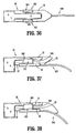
- the roughened surface 88 may include a surface coating 89, as shown in FIG. 29 , or alternatively, the roughened surface 88 may include a glass-bit surface finish 90, as shown in FIG. 30 .
- the anvil component 28 may include a polished tip 91, as also shown in FIG. 30 .
- the polished tip 91 serves to reduce friction between the anvil component 28 and the proximal end 702 of the introducer member 700 in order to allow for sufficient advancement of the anvil component 28 into the hollow 704 to facilitate engagement of the attachment structure 706 with the roughened surface 88.
- the introducer member 800 includes a proximal end 802 and a distal end 804, and is configured and dimensioned for longitudinal movement relative to the end effector 20 ( FIG. 1 ), e.g., the anvil component 28. More specifically, the introducer member 800 is configured and dimensioned for slidable movement through a slot 94 formed in the anvil cover 32 such that the introducer member 800 is selectively repositionable between a retracted position ( FIGS. 31, 32 ) and an advanced position ( FIG. 33 ).
- the distal end 804 of the introducer member 800 In the retracted position, the distal end 804 of the introducer member 800 is positioned proximally of a distal-most tip 95 of the anvil component 28, and in the advanced position, the distal end 804 of the introducer member 800 is positioned distally of the distal-most tip 95 of the anvil component 28 to facilitate separation of the target tissue "T” ( FIG. 9 ) from any collateral tissue "C.”
- the introducer member 800 may include a manual member 806 that is configured and dimensioned for engagement by the clinician.
- the manual member 806 extends upwardly from the introducer member 800, and may be positioned at the proximal end 802 of the introducer member 800, as shown in FIGS. 31-33 , or in any other suitable location.
- the manual member 806 may constitute a roughened surface (not shown) which does not extend upwardly from the introducer member 800, but rather, extends along the plane of the anvil cover 32 ( FIG. 3 ).
- the introducer member 800 may be connected to the end effector 20 ( FIG. 1 ) so as to allow for lateral movement thereof, e.g., side-to-side, as well as longitudinal movement.
- the introducer member 800 may be connected to the anvil component 28 via a pivot member 808 such that the introducer member 800 is movable in the directions indicated by arrows 1 and 2. Allowing for both longitudinal and lateral movement provides the clinician with increased access to internal spaces, which allows the clinician to more accurate place the introducer member 800during navigation around the patient's internal tissues.
- FIGS. 36-38 illustrate another embodiment of the introducer member, which is identified by the reference character 900.
- the introducer member 900 includes a pair of flexible wings 902 with feet 904 that are configured and dimensioned to securely engage the anvil component 28, e.g., the anvil cover 32.
- the feet 904 may be configured and dimensioned to engage the anvil component 28 in snap-fit relation.
- the introducer member 900 further includes a rail 906 ( FIGS. 37, 38 ) that is configured and dimensioned for positioning within the slot 50 formed in the anvil plate 30.
- the rail 906 includes a wall 908 that is configured and dimensioned for engagement with the distal wall 93 defined by the slot 50 to inhibit distal movement of the introducer member 900 relative to the anvil component 28 beyond a predetermined location in order to reduce the likelihood of inadvertent disconnection therefrom.
- the introducer member 900 can be removed from the anvil component 28 by disengaging the feet 904 from the anvil cover 32.
- the wings 902 can be deformed laterally outward, e.g., by rotating the introducer member 900 relative to the anvil component 28.
- FIGS. 39 and 40 illustrate another embodiment of the presently disclosed introducer that is identified by the reference character 1000.
- the introducer member 1000 is mounted to the anvil component 28 by a pivot member 1002 that extends through the introducer 1000 and one or more pivot plates 1004 that are secured to an outer surface of the end effector 20.
- the pivot member 1002 may be any member suitable for the intended purpose of facilitating lateral pivotal movement of the introducer member 1000, i.e., side-to-side in the direction indicated by arrows 1 ( FIG. 39 ), including but not limited to screws, rivets, or the like.
- the introducer member 1000 may be utilized in connection with end effectors 20 of various configurations.
- the introducer member 1000 may be employed in connection with an anvil component 28 having a substantially linear configuration ( see FIG. 41 ), or alternatively, with an anvil component 28 that includes the aforementioned dissector portion 83, as shown in FIG. 40 .
- the introducer member 1100 includes a proximal end 1102 with a collar 1104 that is configured and dimensioned for positioning about the anvil cover 32, and a distal portion 1106 that is configured and dimensioned to facilitate separation of the target tissue "T" ( FIG. 9 ) from any collateral tissue "C.”
- the collar 1104 is configured and dimensioned to engage the anvil component 28 such that relative longitudinal movement therebetween is substantially inhibited.
- the collar 1104 may comprise an at least partially resilient material allowing the collar 1104 to be deformed outwardly upon association with the anvil component 28 in order to facilitate a snap-fit connection with the anvil cover 32.
- the distal portion 1106 of the introducer member 1100 may include one or more tabs 1108, snaps, protrusions, or the like that are configured and dimensioned for engagement with corresponding structure in the anvil cover 32, as shown in FIG. 41 .
- the introducer member 1200 includes a proximal end 1202 incorporating attachment structure 11204, a distal end 1206 including an atraumatic tip portion 1208, and an elongate body portion 1210. As illustrated in FIG. 43 , the elongate body portion 1210 of the introducer member 1200 may include a tapered configuration to facilitate separation of the target tissue "T” ( FIG. 9 ) from any collateral tissue "C.”
- the proximal end 1202 of the introducer member 1200 is configured and dimensioned for insertion into the opening 92 formed at the distal end 28A of the anvil component 28 such that the introducer member 1200 is positionable between the anvil cover 32 ( FIG. 3 ) and the anvil plate 30.
- the proximal end 1202 of the introducer member 1200 and the distal end 28A of the anvil component 28 may include corresponding structure that is configured and dimensioned for mating engagement. For example, in the embodiment shown in FIG.
- the attachment structure 1204 included at the proximal end 1202 of the introducer member 1200 may be configured and dimensioned for connection with corresponding engagement structure 96 formed within the opening 92 at the distal end 28A of the anvil component 28 in a press-fit arrangement.
- the attachment structure 1204 is depicted as including a plurality of protrusions 1212, and the engagement structure 96 is depicted as including recesses 97 of corresponding configuration and dimensions. It should be appreciated, however, that alternative configurations for the attachment structure 1204 and the engagement structure 96 are not beyond the scope of the present disclosure.
- the introducer member 1200 is illustrated as including a configuration similar to that of the dissector portion 83 ( FIGS. 1 , 3 , 15 ), in alternative embodiments of the present disclosure, it is envisioned that the introducer member 1200 may assume other configurations.
- the introducer member 1200 may include a more elongate configuration similar to that of the introducer member 100 discussed above with respect to FIGS. 1-10 .
- the attachment structure 1204 included at the proximal end 1202 of the introducer member 1200 may include a stem 1214 with a head portion 1216 attached thereto that is configured and dimensioned for positioning within the opening 92 ( FIG. 43 ) formed at the distal end 28A of the anvil component 28.
- the engagement structure 96 included at the distal end 28A of the anvil component 28 may include a pair of shoulders 98 defining a gap "G" ( FIG. 45 ) therebetween.
- the transverse dimension of the gap "G" is larger than the transverse dimension of the stem 1214, but smaller than the transverse dimension of the head portion 1216, in order to prevent inadvertent disconnection of the introducer member 1200 from the anvil component 28.
- the distal end 28A of the anvil component 28 may be formed from a first material, e.g., a rigid material, such as solid or sheet metal, and that the introducer member 1200 may be formed from a second, more flexible material, such as plastic or rubber.
- a first material e.g., a rigid material, such as solid or sheet metal
- the introducer member 1200 may be formed from a second, more flexible material, such as plastic or rubber.
- the attachment structure 1204 included at the proximal end 1202 of the introducer member 1200 may be heat-staked to the distal end 28A of the anvil component 28.
- FIG. 46 illustrates another embodiment of the presently disclosed introducer member, which is identified by the reference character 1300, that includes a proximal portion 1302 and a distal portion 1304.
- the proximal portion 1302 of the introducer member 1300 includes an outer layer 1306 and an inner layer 1308 which collectively define a cavity 1310 therebetween, as well as a hollow 1312 that is configured and dimensioned to receive the end effector 20 ( FIG. 1 ), e.g., the anvil component 28 ( FIG. 2, 3 ) or the surgical fastener cartridge 34 ( FIG. 2 ).
- the introducer member 1300 further includes a passage 1314 extending longitudinally therethrough that is in fluid communication with the cavity 1310 and a port 1316 included on the distal portion 1304 of the introducer member 1300.
- the passage 1314 allows for the communication of a fluid, such as air or saline, through the port 1316 and into the cavity 1310 to thereby fill and inflate the cavity 1310.
- the port 1316 may include a seal (not shown), valve, or the like to inhibit the escape of fluid from the cavity 1310 and/or the port 1316 until such time that deflation of the cavity 1310 is desired.
- the hollow 1312 at the proximal end 1302 of the introducer member 1300 Prior to inflation of the cavity 1310, the hollow 1312 at the proximal end 1302 of the introducer member 1300 defines a transverse dimension that is smaller than the transverse dimension defined by the component of the end effector 20 to which the introducer member 1300 is to be attached, e.g., a transverse dimension that is smaller than that of the anvil component 28 or the surgical fastener cartridge 34.
- the transverse dimension of the hollow 1312 is increased such that the end effector 20, or component thereof, is positionable within the hollow 1312.
- the clinician can optionally deflate the cavity 1310 by draining the inflation fluid.
- the fluid within the cavity 1310 may exert pressure upon the outer layer 1306 and the inner layer 1308, and that this pressure may be transmitted to an outer surface of the end effector 20 ( FIG. 1 ), thus assisting in retention of the proximal portion 1302 of the introducer member 1300 about the end effector 20.
- either or both of the outer layer 1306 and the inner layer 1308 comprising the proximal portion 1302 of the introducer member 1300 may be formed from a resilient material, e.g., materials with a relatively low durometer, such as shrink tubing.
- FIG. 47 illustrates another embodiment of the presently disclosed introducer member, which is identified by the reference character 1400.
- the introducer member 1400 includes a proximal portion 1402 including a selectively deformable section 1404, and a distal portion 1406 that is positionable about the deformable section 1404.
- the deformable section 1404 includes a resilient member 1408 that is formed from a deformable, e.g., malleable, material that can be manually reconfigured by the clinician in order to assume a desired geometrical configuration.
- the resilient member 1408 may include a flexible shaft 1410 that is connected, either directly or operatively, to the end effector 20, as shown in FIG. 47 .
- the flexible shaft 1410 is connected to the end effector 20 via attachment structure 1412 formed, either integrally or releasably, with the end effector 20, e.g., between the anvil plate 30 ( FIG. 3 ) and the anvil cover 32.
- the distal portion 1406 of the introducer member 1400 is formed from a material that is at least partially resilient in order to facilitate atraumatic advancement of the introducer member 1400 during a surgical procedure, such that introducer member 1400 can be effectively navigated about the target tissue "T” ( FIG. 9 ) and any collateral tissue “C” without causing unnecessary trauma.
- the distal portion 1406 includes an internal cavity 1414 that is configured and dimensioned to receive the deformable section 1404.
- the distal portion 1406 may be attached to the proximal portion 1402 in any suitable manner, such as, for example, through the incorporation of a resilient material.
- a resilient material allows the distal portion 1406 to be forced over the deformable section 1404 and/or the attachment structure 1412 such that the proximal portion 1402 and the distal portion 1406 engage one another in a force-fit arrangement.
- the proximal portion 1402 and the distal portion 1406 may include corresponding structure that is configured and dimensioned for releasable, mating engagement, such as that described in connection with several of the embodiments of the introducer member discussed herein above.
- the introducer member 1400 is illustrated as including an elongate configuration similar to that of the introducer member 100 discussed above with respect to FIGS. 1-10 , in alternative embodiments of the present disclosure, it is envisioned that the introducer member 1400 may assume other configurations.
- the introducer member 1200 may include a configuration similar to that of the dissector portion 83 ( FIGS. 1 , 3 , 15 ).
- the introducer member may be adapted for use with any surgical instrument suitable for the intended purpose of applying the plurality of surgical fasteners 36 ( FIG. 2 ) to a section of tissue, and thereafter severing the tissue along a cut-line.
- the presently disclosed introducer member may alternatively be adapted for use with a surgical stapling apparatus 3000 ( FIG. 49 ), such as that disclosed in commonly assigned U.S. Pat. No. 7,334,717 , currently assigned to Tyco Healthcare Group LP, the contents of which are hereby incorporated by reference herein in its entirety.
- the surgical stapling apparatus 3000 includes a cartridge receiving half-section 3002, which accommodates a plurality of surgical fasteners, and an anvil half-section 3004.
- the half-sections 3002, 3004 are pivotally connected via handles 3006, 3008 for approximation during use.
- the surgical fastener applying apparatus 3000 is fired by driving a firing slide 3010 distally through the advancement of a firing lever 3012. Distal movement of the firing slide 3010 causes a plurality of cam bars to engage camming surfaces that interact with a plurality of pushers to expel the plurality of surgical fasteners from the cartridge receiving half-section 3002.
- the surgical fasteners are positioned on either side of a track which guides a knife during longitudinal movement to thereby sever tissue along a cut-line.
- the surgical fastener applying apparatus 4000 includes an approximation lever 4001, a movable handle 4002, an elongated portion 4004 that extends distally from the handle 4002, and an arm 4006 that extends from a distal end 4008 of the elongated portion 4004.
- the surgical fastener applying apparatus 4000 further includes a end effector 4010 that includes an anvil 4012 that is orthogonally affixed to the arm 4006, and a surgical fastener cartridge receiver 4014 that is operatively coupled to the distal end 4008 of the elongated portion 4004 for retention of the surgical fastener cartridge 200.
- the approximation lever 4001 Prior to firing of the surgical fastener applying apparatus 4000, the approximation lever 4001 is actuated to distally advance a drive member that is operatively connected to the surgical fastener cartridge 200 to move the surgical fastener cartridge 200 towards the anvil 4012, which remains stationary, and capture tissue therebetween. Thereafter, the handle 4002 is moved to advance a pusher bar distally through the elongated portion 4004 to cause corresponding movement of a head portion included at the distal end of the pusher bar.
- the head portion includes a plurality of fingers extending distally therefrom that are configured and dimensioned to engage the cartridge assembly to thereby discharge the plurality of surgical fasteners retained therein. Upon discharge, the surgical fasteners are driven through the tissue and into the anvil 4012 for formation.
- the presently disclosed introducer member may be adapted for use with any of the other surgical fastener applying apparatus discussed in commonly owned U.S. Pat. Nos. 6,045,560 ; 5,964,394 ; 5,894,979 ; 5,878,937 ; 5,915,616 ; 5,836,503 ; 5,865,361 ; 5,862,972 ; 5,817,109 ; 5,797,538 ; and 5,782,396 , the disclosures of which are hereby incorporated by reference herein in their entirety.
- the disclosed surgical fastener applying apparatus may include a plurality of cam bars for interacting with the pushers to deploy the surgical fasteners.
- the apparatus disclosed in commonly owned U.S. Pat. No. 5,318,221 includes a cam bar adapter that holds a plurality of cam bars and a knife, as well as a channel that is advanced through operation of the handle of the apparatus, which drives the cam bars and knife forward.
- the apparatus further includes a clamp tube that is movable to surround the proximal end of the anvil.
- the apparatus disclosed in U.S. Pat. No. 5,782,396 includes an actuation sled and an elongated drive beam that is advanced distally through operation of the handle of the apparatus, driving the actuation sled forward.
- the distal end of the drive beam engages the anvil and the channel that supports the surgical fastener cartridge as the drive beam travels distally to deploy the staples and clamp the anvil and surgical fastener cartridge together.
Applications Claiming Priority (2)
| Application Number | Priority Date | Filing Date | Title |
|---|---|---|---|
| US12/571,659 US8136711B2 (en) | 2006-09-08 | 2009-10-01 | Dissection tip and introducer for surgical instrument |
| EP10251721.6A EP2314230B1 (en) | 2009-10-01 | 2010-10-01 | Dissection tip and introducer for surgical instrument |
Related Parent Applications (2)
| Application Number | Title | Priority Date | Filing Date |
|---|---|---|---|
| EP10251721.6A Division EP2314230B1 (en) | 2009-10-01 | 2010-10-01 | Dissection tip and introducer for surgical instrument |
| EP10251721.6A Division-Into EP2314230B1 (en) | 2009-10-01 | 2010-10-01 | Dissection tip and introducer for surgical instrument |
Publications (2)
| Publication Number | Publication Date |
|---|---|
| EP3138509A1 true EP3138509A1 (en) | 2017-03-08 |
| EP3138509B1 EP3138509B1 (en) | 2020-04-01 |
Family
ID=43569152
Family Applications (2)
| Application Number | Title | Priority Date | Filing Date |
|---|---|---|---|
| EP10251721.6A Active EP2314230B1 (en) | 2009-10-01 | 2010-10-01 | Dissection tip and introducer for surgical instrument |
| EP16183321.5A Active EP3138509B1 (en) | 2009-10-01 | 2010-10-01 | Dissection tip and introducer for surgical instrument |
Family Applications Before (1)
| Application Number | Title | Priority Date | Filing Date |
|---|---|---|---|
| EP10251721.6A Active EP2314230B1 (en) | 2009-10-01 | 2010-10-01 | Dissection tip and introducer for surgical instrument |
Country Status (7)
| Country | Link |
|---|---|
| US (2) | US8136711B2 (es) |
| EP (2) | EP2314230B1 (es) |
| JP (2) | JP5562788B2 (es) |
| CN (1) | CN102048566B (es) |
| AU (1) | AU2010226932B2 (es) |
| CA (1) | CA2716151C (es) |
| ES (1) | ES2611473T3 (es) |
Cited By (3)
| Publication number | Priority date | Publication date | Assignee | Title |
|---|---|---|---|---|
| EP3892208A3 (en) * | 2020-04-07 | 2021-12-22 | Covidien LP | Surgical stapling device with adjustable dissecting tip |
| US11864761B2 (en) | 2021-09-14 | 2024-01-09 | Covidien Lp | Surgical instrument with illumination mechanism |
| US11890014B2 (en) | 2020-02-14 | 2024-02-06 | Covidien Lp | Cartridge holder for surgical staples and having ridges in peripheral walls for gripping tissue |
Families Citing this family (587)
| Publication number | Priority date | Publication date | Assignee | Title |
|---|---|---|---|---|
| US5865361A (en) | 1997-09-23 | 1999-02-02 | United States Surgical Corporation | Surgical stapling apparatus |
| US8714429B2 (en) | 2003-04-29 | 2014-05-06 | Covidien Lp | Dissecting tip for surgical stapler |
| US20040243151A1 (en) * | 2003-04-29 | 2004-12-02 | Demmy Todd L. | Surgical stapling device with dissecting tip |
| US9060770B2 (en) | 2003-05-20 | 2015-06-23 | Ethicon Endo-Surgery, Inc. | Robotically-driven surgical instrument with E-beam driver |
| US20070084897A1 (en) | 2003-05-20 | 2007-04-19 | Shelton Frederick E Iv | Articulating surgical stapling instrument incorporating a two-piece e-beam firing mechanism |
| EP1680028B1 (en) | 2003-10-17 | 2012-01-25 | Tyco Healthcare Group LP | Surgical stapling device |
| US8215531B2 (en) | 2004-07-28 | 2012-07-10 | Ethicon Endo-Surgery, Inc. | Surgical stapling instrument having a medical substance dispenser |
| US11890012B2 (en) | 2004-07-28 | 2024-02-06 | Cilag Gmbh International | Staple cartridge comprising cartridge body and attached support |
| US7669746B2 (en) | 2005-08-31 | 2010-03-02 | Ethicon Endo-Surgery, Inc. | Staple cartridges for forming staples having differing formed staple heights |
| US11246590B2 (en) | 2005-08-31 | 2022-02-15 | Cilag Gmbh International | Staple cartridge including staple drivers having different unfired heights |
| US9237891B2 (en) | 2005-08-31 | 2016-01-19 | Ethicon Endo-Surgery, Inc. | Robotically-controlled surgical stapling devices that produce formed staples having different lengths |
| US11484312B2 (en) | 2005-08-31 | 2022-11-01 | Cilag Gmbh International | Staple cartridge comprising a staple driver arrangement |
| US10159482B2 (en) | 2005-08-31 | 2018-12-25 | Ethicon Llc | Fastener cartridge assembly comprising a fixed anvil and different staple heights |
| US7934630B2 (en) | 2005-08-31 | 2011-05-03 | Ethicon Endo-Surgery, Inc. | Staple cartridges for forming staples having differing formed staple heights |
| US20070106317A1 (en) | 2005-11-09 | 2007-05-10 | Shelton Frederick E Iv | Hydraulically and electrically actuated articulation joints for surgical instruments |
| US8186555B2 (en) | 2006-01-31 | 2012-05-29 | Ethicon Endo-Surgery, Inc. | Motor-driven surgical cutting and fastening instrument with mechanical closure system |
| US8820603B2 (en) | 2006-01-31 | 2014-09-02 | Ethicon Endo-Surgery, Inc. | Accessing data stored in a memory of a surgical instrument |
| US11793518B2 (en) | 2006-01-31 | 2023-10-24 | Cilag Gmbh International | Powered surgical instruments with firing system lockout arrangements |
| US7845537B2 (en) | 2006-01-31 | 2010-12-07 | Ethicon Endo-Surgery, Inc. | Surgical instrument having recording capabilities |
| US20110024477A1 (en) | 2009-02-06 | 2011-02-03 | Hall Steven G | Driven Surgical Stapler Improvements |
| US7753904B2 (en) | 2006-01-31 | 2010-07-13 | Ethicon Endo-Surgery, Inc. | Endoscopic surgical instrument with a handle that can articulate with respect to the shaft |
| US11224427B2 (en) | 2006-01-31 | 2022-01-18 | Cilag Gmbh International | Surgical stapling system including a console and retraction assembly |
| US20120292367A1 (en) | 2006-01-31 | 2012-11-22 | Ethicon Endo-Surgery, Inc. | Robotically-controlled end effector |
| US11278279B2 (en) | 2006-01-31 | 2022-03-22 | Cilag Gmbh International | Surgical instrument assembly |
| US8708213B2 (en) | 2006-01-31 | 2014-04-29 | Ethicon Endo-Surgery, Inc. | Surgical instrument having a feedback system |
| US20110290856A1 (en) | 2006-01-31 | 2011-12-01 | Ethicon Endo-Surgery, Inc. | Robotically-controlled surgical instrument with force-feedback capabilities |
| US8992422B2 (en) | 2006-03-23 | 2015-03-31 | Ethicon Endo-Surgery, Inc. | Robotically-controlled endoscopic accessory channel |
| US8322455B2 (en) | 2006-06-27 | 2012-12-04 | Ethicon Endo-Surgery, Inc. | Manually driven surgical cutting and fastening instrument |
| US8136711B2 (en) * | 2006-09-08 | 2012-03-20 | Tyco Healthcare Group Lp | Dissection tip and introducer for surgical instrument |
| US8403196B2 (en) | 2006-09-08 | 2013-03-26 | Covidien Lp | Dissection tip and introducer for surgical instrument |
| US10568652B2 (en) | 2006-09-29 | 2020-02-25 | Ethicon Llc | Surgical staples having attached drivers of different heights and stapling instruments for deploying the same |
| US7506791B2 (en) | 2006-09-29 | 2009-03-24 | Ethicon Endo-Surgery, Inc. | Surgical stapling instrument with mechanical mechanism for limiting maximum tissue compression |
| US7845535B2 (en) | 2006-10-06 | 2010-12-07 | Tyco Healthcare Group Lp | Surgical instrument having a plastic surface |
| US8652120B2 (en) | 2007-01-10 | 2014-02-18 | Ethicon Endo-Surgery, Inc. | Surgical instrument with wireless communication between control unit and sensor transponders |
| US8684253B2 (en) | 2007-01-10 | 2014-04-01 | Ethicon Endo-Surgery, Inc. | Surgical instrument with wireless communication between a control unit of a robotic system and remote sensor |
| US11291441B2 (en) | 2007-01-10 | 2022-04-05 | Cilag Gmbh International | Surgical instrument with wireless communication between control unit and remote sensor |
| US8540128B2 (en) | 2007-01-11 | 2013-09-24 | Ethicon Endo-Surgery, Inc. | Surgical stapling device with a curved end effector |
| US11039836B2 (en) | 2007-01-11 | 2021-06-22 | Cilag Gmbh International | Staple cartridge for use with a surgical stapling instrument |
| US8727197B2 (en) | 2007-03-15 | 2014-05-20 | Ethicon Endo-Surgery, Inc. | Staple cartridge cavity configuration with cooperative surgical staple |
| US8893946B2 (en) | 2007-03-28 | 2014-11-25 | Ethicon Endo-Surgery, Inc. | Laparoscopic tissue thickness and clamp load measuring devices |
| US11857181B2 (en) | 2007-06-04 | 2024-01-02 | Cilag Gmbh International | Robotically-controlled shaft based rotary drive systems for surgical instruments |
| US8931682B2 (en) | 2007-06-04 | 2015-01-13 | Ethicon Endo-Surgery, Inc. | Robotically-controlled shaft based rotary drive systems for surgical instruments |
| US7753245B2 (en) | 2007-06-22 | 2010-07-13 | Ethicon Endo-Surgery, Inc. | Surgical stapling instruments |
| US11849941B2 (en) | 2007-06-29 | 2023-12-26 | Cilag Gmbh International | Staple cartridge having staple cavities extending at a transverse angle relative to a longitudinal cartridge axis |
| US8061576B2 (en) | 2007-08-31 | 2011-11-22 | Tyco Healthcare Group Lp | Surgical instrument |
| US7866523B1 (en) * | 2007-09-21 | 2011-01-11 | Cardica, Inc. | Soft-tipped anvil |
| US8636736B2 (en) | 2008-02-14 | 2014-01-28 | Ethicon Endo-Surgery, Inc. | Motorized surgical cutting and fastening instrument |
| BRPI0901282A2 (pt) | 2008-02-14 | 2009-11-17 | Ethicon Endo Surgery Inc | instrumento cirúrgico de corte e fixação dotado de eletrodos de rf |
| US8573465B2 (en) | 2008-02-14 | 2013-11-05 | Ethicon Endo-Surgery, Inc. | Robotically-controlled surgical end effector system with rotary actuated closure systems |
| US8758391B2 (en) | 2008-02-14 | 2014-06-24 | Ethicon Endo-Surgery, Inc. | Interchangeable tools for surgical instruments |
| US7866527B2 (en) | 2008-02-14 | 2011-01-11 | Ethicon Endo-Surgery, Inc. | Surgical stapling apparatus with interlockable firing system |
| US9179912B2 (en) | 2008-02-14 | 2015-11-10 | Ethicon Endo-Surgery, Inc. | Robotically-controlled motorized surgical cutting and fastening instrument |
| US7819298B2 (en) | 2008-02-14 | 2010-10-26 | Ethicon Endo-Surgery, Inc. | Surgical stapling apparatus with control features operable with one hand |
| US11272927B2 (en) | 2008-02-15 | 2022-03-15 | Cilag Gmbh International | Layer arrangements for surgical staple cartridges |
| US9770245B2 (en) | 2008-02-15 | 2017-09-26 | Ethicon Llc | Layer arrangements for surgical staple cartridges |
| WO2009114779A2 (en) * | 2008-03-14 | 2009-09-17 | Safestitch Medical, Inc. | Hernia stapler with integrated mesh manipulator |
| US8870049B2 (en) | 2008-03-14 | 2014-10-28 | Transenterix, Inc. | Hernia stapler |
| US9005230B2 (en) | 2008-09-23 | 2015-04-14 | Ethicon Endo-Surgery, Inc. | Motorized surgical instrument |
| US9386983B2 (en) | 2008-09-23 | 2016-07-12 | Ethicon Endo-Surgery, Llc | Robotically-controlled motorized surgical instrument |
| US7988028B2 (en) | 2008-09-23 | 2011-08-02 | Tyco Healthcare Group Lp | Surgical instrument having an asymmetric dynamic clamping member |
| US11648005B2 (en) | 2008-09-23 | 2023-05-16 | Cilag Gmbh International | Robotically-controlled motorized surgical instrument with an end effector |
| US8628544B2 (en) | 2008-09-23 | 2014-01-14 | Covidien Lp | Knife bar for surgical instrument |
| US8210411B2 (en) | 2008-09-23 | 2012-07-03 | Ethicon Endo-Surgery, Inc. | Motor-driven surgical cutting instrument |
| US8608045B2 (en) | 2008-10-10 | 2013-12-17 | Ethicon Endo-Sugery, Inc. | Powered surgical cutting and stapling apparatus with manually retractable firing system |
| US8517239B2 (en) | 2009-02-05 | 2013-08-27 | Ethicon Endo-Surgery, Inc. | Surgical stapling instrument comprising a magnetic element driver |
| US8444036B2 (en) | 2009-02-06 | 2013-05-21 | Ethicon Endo-Surgery, Inc. | Motor driven surgical fastener device with mechanisms for adjusting a tissue gap within the end effector |
| CN102341048A (zh) | 2009-02-06 | 2012-02-01 | 伊西康内外科公司 | 动力手术缝合器的改进 |
| US8851354B2 (en) | 2009-12-24 | 2014-10-07 | Ethicon Endo-Surgery, Inc. | Surgical cutting instrument that analyzes tissue thickness |
| US8220688B2 (en) | 2009-12-24 | 2012-07-17 | Ethicon Endo-Surgery, Inc. | Motor-driven surgical cutting instrument with electric actuator directional control assembly |
| US10219826B2 (en) | 2010-07-14 | 2019-03-05 | Seg-Way Orthopaedics, Inc. | Method and apparatus for endoscopic ligament release |
| US8783543B2 (en) | 2010-07-30 | 2014-07-22 | Ethicon Endo-Surgery, Inc. | Tissue acquisition arrangements and methods for surgical stapling devices |
| US9364233B2 (en) | 2010-09-30 | 2016-06-14 | Ethicon Endo-Surgery, Llc | Tissue thickness compensators for circular surgical staplers |
| US9517063B2 (en) | 2012-03-28 | 2016-12-13 | Ethicon Endo-Surgery, Llc | Movable member for use with a tissue thickness compensator |
| US9016542B2 (en) | 2010-09-30 | 2015-04-28 | Ethicon Endo-Surgery, Inc. | Staple cartridge comprising compressible distortion resistant components |
| US11298125B2 (en) | 2010-09-30 | 2022-04-12 | Cilag Gmbh International | Tissue stapler having a thickness compensator |
| US9211120B2 (en) | 2011-04-29 | 2015-12-15 | Ethicon Endo-Surgery, Inc. | Tissue thickness compensator comprising a plurality of medicaments |
| US9282962B2 (en) | 2010-09-30 | 2016-03-15 | Ethicon Endo-Surgery, Llc | Adhesive film laminate |
| US9629814B2 (en) | 2010-09-30 | 2017-04-25 | Ethicon Endo-Surgery, Llc | Tissue thickness compensator configured to redistribute compressive forces |
| US11812965B2 (en) | 2010-09-30 | 2023-11-14 | Cilag Gmbh International | Layer of material for a surgical end effector |
| US10945731B2 (en) | 2010-09-30 | 2021-03-16 | Ethicon Llc | Tissue thickness compensator comprising controlled release and expansion |
| US9386988B2 (en) | 2010-09-30 | 2016-07-12 | Ethicon End-Surgery, LLC | Retainer assembly including a tissue thickness compensator |
| US11849952B2 (en) | 2010-09-30 | 2023-12-26 | Cilag Gmbh International | Staple cartridge comprising staples positioned within a compressible portion thereof |
| US8695866B2 (en) | 2010-10-01 | 2014-04-15 | Ethicon Endo-Surgery, Inc. | Surgical instrument having a power control circuit |
| CN103476353A (zh) | 2011-02-02 | 2013-12-25 | 山姆·菲利乔托 | 外科系统及其方法 |
| CA2834649C (en) | 2011-04-29 | 2021-02-16 | Ethicon Endo-Surgery, Inc. | Staple cartridge comprising staples positioned within a compressible portion thereof |
| US9072535B2 (en) | 2011-05-27 | 2015-07-07 | Ethicon Endo-Surgery, Inc. | Surgical stapling instruments with rotatable staple deployment arrangements |
| US11207064B2 (en) | 2011-05-27 | 2021-12-28 | Cilag Gmbh International | Automated end effector component reloading system for use with a robotic system |
| US8740036B2 (en) | 2011-12-01 | 2014-06-03 | Covidien Lp | Surgical instrument with actuator spring arm |
| US9549738B2 (en) * | 2012-01-05 | 2017-01-24 | Ethicon Endo-Surgery, Llc | Ratcheting feature on tissue staple trigger to prevent premature jaw opening |
| US9044230B2 (en) | 2012-02-13 | 2015-06-02 | Ethicon Endo-Surgery, Inc. | Surgical cutting and fastening instrument with apparatus for determining cartridge and firing motion status |
| CN104379068B (zh) | 2012-03-28 | 2017-09-22 | 伊西康内外科公司 | 包括组织厚度补偿件的保持器组件 |
| BR112014024098B1 (pt) | 2012-03-28 | 2021-05-25 | Ethicon Endo-Surgery, Inc. | cartucho de grampos |
| BR112014024102B1 (pt) | 2012-03-28 | 2022-03-03 | Ethicon Endo-Surgery, Inc | Conjunto de cartucho de prendedores para um instrumento cirúrgico, e conjunto de atuador de extremidade para um instrumento cirúrgico |
| EP2833802A4 (en) * | 2012-04-04 | 2015-11-18 | Cardica Inc | CARTRIDGE OF SURGICAL STAPLES HAVING A CURABLE HEAD |
| US9101358B2 (en) | 2012-06-15 | 2015-08-11 | Ethicon Endo-Surgery, Inc. | Articulatable surgical instrument comprising a firing drive |
| US9204879B2 (en) | 2012-06-28 | 2015-12-08 | Ethicon Endo-Surgery, Inc. | Flexible drive member |
| US9289256B2 (en) | 2012-06-28 | 2016-03-22 | Ethicon Endo-Surgery, Llc | Surgical end effectors having angled tissue-contacting surfaces |
| US9226751B2 (en) | 2012-06-28 | 2016-01-05 | Ethicon Endo-Surgery, Inc. | Surgical instrument system including replaceable end effectors |
| BR112014032776B1 (pt) | 2012-06-28 | 2021-09-08 | Ethicon Endo-Surgery, Inc | Sistema de instrumento cirúrgico e kit cirúrgico para uso com um sistema de instrumento cirúrgico |
| US9282974B2 (en) | 2012-06-28 | 2016-03-15 | Ethicon Endo-Surgery, Llc | Empty clip cartridge lockout |
| US11278284B2 (en) | 2012-06-28 | 2022-03-22 | Cilag Gmbh International | Rotary drive arrangements for surgical instruments |
| JP6290201B2 (ja) | 2012-06-28 | 2018-03-07 | エシコン・エンド−サージェリィ・インコーポレイテッドEthicon Endo−Surgery,Inc. | 空クリップカートリッジ用のロックアウト |
| US20140001231A1 (en) | 2012-06-28 | 2014-01-02 | Ethicon Endo-Surgery, Inc. | Firing system lockout arrangements for surgical instruments |
| US9364236B2 (en) | 2012-11-09 | 2016-06-14 | Covidien Lp | Slanted introducer for end-to-end anastomosis anvil |
| US8920419B2 (en) | 2012-11-30 | 2014-12-30 | Gyrus Acmi, Inc. | Apparatus and method for tubeset with drive axle |
| JP6306039B2 (ja) * | 2012-11-30 | 2018-04-04 | ジャイラス・エーシーエムアイ・インコーポレーテッド | 取り替え可能な交換可能部品を備えるマイクロデブリッダー、および部品を取り付ける方法 |
| US9622746B2 (en) * | 2013-02-28 | 2017-04-18 | Ethicon Endo-Surgery, Llc | Distal tip features for end effector of surgical instrument |
| US9808248B2 (en) * | 2013-02-28 | 2017-11-07 | Ethicon Llc | Installation features for surgical instrument end effector cartridge |
| JP6345707B2 (ja) | 2013-03-01 | 2018-06-20 | エシコン・エンド−サージェリィ・インコーポレイテッドEthicon Endo−Surgery,Inc. | ソフトストップを備えた外科用器具 |
| JP6382235B2 (ja) | 2013-03-01 | 2018-08-29 | エシコン・エンド−サージェリィ・インコーポレイテッドEthicon Endo−Surgery,Inc. | 信号通信用の導電路を備えた関節運動可能な外科用器具 |
| US9936951B2 (en) * | 2013-03-12 | 2018-04-10 | Covidien Lp | Interchangeable tip reload |
| US9717498B2 (en) | 2013-03-13 | 2017-08-01 | Covidien Lp | Surgical stapling apparatus |
| US9629628B2 (en) | 2013-03-13 | 2017-04-25 | Covidien Lp | Surgical stapling apparatus |
| US9888921B2 (en) | 2013-03-13 | 2018-02-13 | Covidien Lp | Surgical stapling apparatus |
| US9814463B2 (en) | 2013-03-13 | 2017-11-14 | Covidien Lp | Surgical stapling apparatus |
| US9629629B2 (en) | 2013-03-14 | 2017-04-25 | Ethicon Endo-Surgey, LLC | Control systems for surgical instruments |
| US9332987B2 (en) | 2013-03-14 | 2016-05-10 | Ethicon Endo-Surgery, Llc | Control arrangements for a drive member of a surgical instrument |
| US20140263558A1 (en) | 2013-03-15 | 2014-09-18 | Cardica, Inc. | Extended curved tip for surgical apparatus |
| BR112015026109B1 (pt) | 2013-04-16 | 2022-02-22 | Ethicon Endo-Surgery, Inc | Instrumento cirúrgico |
| US9844368B2 (en) | 2013-04-16 | 2017-12-19 | Ethicon Llc | Surgical system comprising first and second drive systems |
| US20150053746A1 (en) | 2013-08-23 | 2015-02-26 | Ethicon Endo-Surgery, Inc. | Torque optimization for surgical instruments |
| JP6416260B2 (ja) | 2013-08-23 | 2018-10-31 | エシコン エルエルシー | 動力付き外科用器具のための発射部材後退装置 |
| US9662108B2 (en) | 2013-08-30 | 2017-05-30 | Covidien Lp | Surgical stapling apparatus |
| US9642642B2 (en) * | 2013-09-20 | 2017-05-09 | Kok Hoo LIM | Guide tip introducer and method to create thereof |
| CN105682568B (zh) | 2013-11-04 | 2018-10-23 | 柯惠Lp公司 | 手术紧固件施加装置 |
| AU2013403916A1 (en) | 2013-11-04 | 2016-04-28 | Covidien Lp | Surgical fastener applying apparatus |
| CA2926750A1 (en) | 2013-11-04 | 2015-05-07 | Covidien Lp | Surgical fastener applying apparatus |
| US9867613B2 (en) | 2013-12-19 | 2018-01-16 | Covidien Lp | Surgical staples and end effectors for deploying the same |
| US9700312B2 (en) | 2014-01-28 | 2017-07-11 | Covidien Lp | Surgical apparatus |
| US9936952B2 (en) | 2014-02-03 | 2018-04-10 | Covidien Lp | Introducer assembly for a surgical fastener applying apparatus |
| US9962161B2 (en) | 2014-02-12 | 2018-05-08 | Ethicon Llc | Deliverable surgical instrument |
| US9848874B2 (en) | 2014-02-14 | 2017-12-26 | Covidien Lp | Small diameter endoscopic stapler |
| CN106232029B (zh) | 2014-02-24 | 2019-04-12 | 伊西康内外科有限责任公司 | 包括击发构件锁定件的紧固系统 |
| US10004497B2 (en) | 2014-03-26 | 2018-06-26 | Ethicon Llc | Interface systems for use with surgical instruments |
| BR112016021943B1 (pt) | 2014-03-26 | 2022-06-14 | Ethicon Endo-Surgery, Llc | Instrumento cirúrgico para uso por um operador em um procedimento cirúrgico |
| US9733663B2 (en) | 2014-03-26 | 2017-08-15 | Ethicon Llc | Power management through segmented circuit and variable voltage protection |
| US9757126B2 (en) | 2014-03-31 | 2017-09-12 | Covidien Lp | Surgical stapling apparatus with firing lockout mechanism |
| JP6532889B2 (ja) | 2014-04-16 | 2019-06-19 | エシコン エルエルシーEthicon LLC | 締結具カートリッジ組立体及びステープル保持具カバー配置構成 |
| US10561422B2 (en) | 2014-04-16 | 2020-02-18 | Ethicon Llc | Fastener cartridge comprising deployable tissue engaging members |
| US20150297223A1 (en) | 2014-04-16 | 2015-10-22 | Ethicon Endo-Surgery, Inc. | Fastener cartridges including extensions having different configurations |
| JP6636452B2 (ja) | 2014-04-16 | 2020-01-29 | エシコン エルエルシーEthicon LLC | 異なる構成を有する延在部を含む締結具カートリッジ |
| US10327764B2 (en) | 2014-09-26 | 2019-06-25 | Ethicon Llc | Method for creating a flexible staple line |
| BR112016023825B1 (pt) | 2014-04-16 | 2022-08-02 | Ethicon Endo-Surgery, Llc | Cartucho de grampos para uso com um grampeador cirúrgico e cartucho de grampos para uso com um instrumento cirúrgico |
| US9668733B2 (en) | 2014-04-21 | 2017-06-06 | Covidien Lp | Stapling device with features to prevent inadvertent firing of staples |
| US9861366B2 (en) | 2014-05-06 | 2018-01-09 | Covidien Lp | Ejecting assembly for a surgical stapler |
| EP3142569B1 (en) | 2014-05-15 | 2023-12-27 | Covidien LP | Surgical fastener applying apparatus |
| US11311294B2 (en) | 2014-09-05 | 2022-04-26 | Cilag Gmbh International | Powered medical device including measurement of closure state of jaws |
| BR112017004361B1 (pt) | 2014-09-05 | 2023-04-11 | Ethicon Llc | Sistema eletrônico para um instrumento cirúrgico |
| US10111679B2 (en) | 2014-09-05 | 2018-10-30 | Ethicon Llc | Circuitry and sensors for powered medical device |
| US10105142B2 (en) | 2014-09-18 | 2018-10-23 | Ethicon Llc | Surgical stapler with plurality of cutting elements |
| JP6648119B2 (ja) | 2014-09-26 | 2020-02-14 | エシコン エルエルシーEthicon LLC | 外科ステープル留めバットレス及び付属物材料 |
| US11523821B2 (en) | 2014-09-26 | 2022-12-13 | Cilag Gmbh International | Method for creating a flexible staple line |
| US10076325B2 (en) | 2014-10-13 | 2018-09-18 | Ethicon Llc | Surgical stapling apparatus comprising a tissue stop |
| US9924944B2 (en) | 2014-10-16 | 2018-03-27 | Ethicon Llc | Staple cartridge comprising an adjunct material |
| US11141153B2 (en) | 2014-10-29 | 2021-10-12 | Cilag Gmbh International | Staple cartridges comprising driver arrangements |
| US10517594B2 (en) * | 2014-10-29 | 2019-12-31 | Ethicon Llc | Cartridge assemblies for surgical staplers |
| US9844376B2 (en) | 2014-11-06 | 2017-12-19 | Ethicon Llc | Staple cartridge comprising a releasable adjunct material |
| US10736636B2 (en) | 2014-12-10 | 2020-08-11 | Ethicon Llc | Articulatable surgical instrument system |
| US10004501B2 (en) | 2014-12-18 | 2018-06-26 | Ethicon Llc | Surgical instruments with improved closure arrangements |
| US9987000B2 (en) | 2014-12-18 | 2018-06-05 | Ethicon Llc | Surgical instrument assembly comprising a flexible articulation system |
| US9844375B2 (en) | 2014-12-18 | 2017-12-19 | Ethicon Llc | Drive arrangements for articulatable surgical instruments |
| US9844374B2 (en) | 2014-12-18 | 2017-12-19 | Ethicon Llc | Surgical instrument systems comprising an articulatable end effector and means for adjusting the firing stroke of a firing member |
| MX2017008108A (es) | 2014-12-18 | 2018-03-06 | Ethicon Llc | Instrumento quirurgico con un yunque que puede moverse de manera selectiva sobre un eje discreto no movil con relacion a un cartucho de grapas. |
| US10085748B2 (en) | 2014-12-18 | 2018-10-02 | Ethicon Llc | Locking arrangements for detachable shaft assemblies with articulatable surgical end effectors |
| US10039545B2 (en) | 2015-02-23 | 2018-08-07 | Covidien Lp | Double fire stapling |
| US10130367B2 (en) | 2015-02-26 | 2018-11-20 | Covidien Lp | Surgical apparatus |
| US10085749B2 (en) | 2015-02-26 | 2018-10-02 | Covidien Lp | Surgical apparatus with conductor strain relief |
| US11154301B2 (en) | 2015-02-27 | 2021-10-26 | Cilag Gmbh International | Modular stapling assembly |
| US10321907B2 (en) | 2015-02-27 | 2019-06-18 | Ethicon Llc | System for monitoring whether a surgical instrument needs to be serviced |
| US20160256159A1 (en) * | 2015-03-05 | 2016-09-08 | Covidien Lp | Jaw members and methods of manufacture |
| US10687806B2 (en) | 2015-03-06 | 2020-06-23 | Ethicon Llc | Adaptive tissue compression techniques to adjust closure rates for multiple tissue types |
| US9993248B2 (en) | 2015-03-06 | 2018-06-12 | Ethicon Endo-Surgery, Llc | Smart sensors with local signal processing |
| US9808246B2 (en) | 2015-03-06 | 2017-11-07 | Ethicon Endo-Surgery, Llc | Method of operating a powered surgical instrument |
| US10441279B2 (en) | 2015-03-06 | 2019-10-15 | Ethicon Llc | Multiple level thresholds to modify operation of powered surgical instruments |
| US9901342B2 (en) | 2015-03-06 | 2018-02-27 | Ethicon Endo-Surgery, Llc | Signal and power communication system positioned on a rotatable shaft |
| JP2020121162A (ja) | 2015-03-06 | 2020-08-13 | エシコン エルエルシーEthicon LLC | 測定の安定性要素、クリープ要素、及び粘弾性要素を決定するためのセンサデータの時間依存性評価 |
| US10617412B2 (en) | 2015-03-06 | 2020-04-14 | Ethicon Llc | System for detecting the mis-insertion of a staple cartridge into a surgical stapler |
| US10245033B2 (en) | 2015-03-06 | 2019-04-02 | Ethicon Llc | Surgical instrument comprising a lockable battery housing |
| US9924961B2 (en) | 2015-03-06 | 2018-03-27 | Ethicon Endo-Surgery, Llc | Interactive feedback system for powered surgical instruments |
| US10548504B2 (en) | 2015-03-06 | 2020-02-04 | Ethicon Llc | Overlaid multi sensor radio frequency (RF) electrode system to measure tissue compression |
| US9918717B2 (en) | 2015-03-18 | 2018-03-20 | Covidien Lp | Pivot mechanism for surgical device |
| US10213201B2 (en) | 2015-03-31 | 2019-02-26 | Ethicon Llc | Stapling end effector configured to compensate for an uneven gap between a first jaw and a second jaw |
| US10463368B2 (en) | 2015-04-10 | 2019-11-05 | Covidien Lp | Endoscopic stapler |
| US10299789B2 (en) | 2015-05-05 | 2019-05-28 | Covidie LP | Adapter assembly for surgical stapling devices |
| US10117650B2 (en) | 2015-05-05 | 2018-11-06 | Covidien Lp | Adapter assembly and loading units for surgical stapling devices |
| US10039532B2 (en) | 2015-05-06 | 2018-08-07 | Covidien Lp | Surgical instrument with articulation assembly |
| US10349941B2 (en) | 2015-05-27 | 2019-07-16 | Covidien Lp | Multi-fire lead screw stapling device |
| US10172615B2 (en) | 2015-05-27 | 2019-01-08 | Covidien Lp | Multi-fire push rod stapling device |
| US10548599B2 (en) | 2015-07-20 | 2020-02-04 | Covidien Lp | Endoscopic stapler and staple |
| US9987012B2 (en) | 2015-07-21 | 2018-06-05 | Covidien Lp | Small diameter cartridge design for a surgical stapling instrument |
| US10194912B2 (en) * | 2015-07-28 | 2019-02-05 | Ethicon Llc | Surgical staple cartridge with outer edge compression features |
| US10064622B2 (en) | 2015-07-29 | 2018-09-04 | Covidien Lp | Surgical stapling loading unit with stroke counter and lockout |
| US10045782B2 (en) | 2015-07-30 | 2018-08-14 | Covidien Lp | Surgical stapling loading unit with stroke counter and lockout |
| US11058425B2 (en) | 2015-08-17 | 2021-07-13 | Ethicon Llc | Implantable layers for a surgical instrument |
| CN105125247A (zh) * | 2015-08-28 | 2015-12-09 | 常州华森医疗器械有限公司 | 一种带翘头的腔镜直线切割闭合器的抵钉槽 |
| US10363036B2 (en) | 2015-09-23 | 2019-07-30 | Ethicon Llc | Surgical stapler having force-based motor control |
| US10105139B2 (en) | 2015-09-23 | 2018-10-23 | Ethicon Llc | Surgical stapler having downstream current-based motor control |
| US10327769B2 (en) | 2015-09-23 | 2019-06-25 | Ethicon Llc | Surgical stapler having motor control based on a drive system component |
| US10238386B2 (en) | 2015-09-23 | 2019-03-26 | Ethicon Llc | Surgical stapler having motor control based on an electrical parameter related to a motor current |
| US10299878B2 (en) | 2015-09-25 | 2019-05-28 | Ethicon Llc | Implantable adjunct systems for determining adjunct skew |
| US11890015B2 (en) | 2015-09-30 | 2024-02-06 | Cilag Gmbh International | Compressible adjunct with crossing spacer fibers |
| US10980539B2 (en) | 2015-09-30 | 2021-04-20 | Ethicon Llc | Implantable adjunct comprising bonded layers |
| US10327777B2 (en) | 2015-09-30 | 2019-06-25 | Ethicon Llc | Implantable layer comprising plastically deformed fibers |
| US10285699B2 (en) | 2015-09-30 | 2019-05-14 | Ethicon Llc | Compressible adjunct |
| US10213204B2 (en) | 2015-10-02 | 2019-02-26 | Covidien Lp | Micro surgical instrument and loading unit for use therewith |
| US10772632B2 (en) | 2015-10-28 | 2020-09-15 | Covidien Lp | Surgical stapling device with triple leg staples |
| WO2017083129A1 (en) * | 2015-11-13 | 2017-05-18 | Intuitive Surgical Operations, Inc. | Stapler anvil with compliant tip |
| US10595864B2 (en) | 2015-11-24 | 2020-03-24 | Covidien Lp | Adapter assembly for interconnecting electromechanical surgical devices and surgical loading units, and surgical systems thereof |
| US10111660B2 (en) | 2015-12-03 | 2018-10-30 | Covidien Lp | Surgical stapler flexible distal tip |
| US10368865B2 (en) | 2015-12-30 | 2019-08-06 | Ethicon Llc | Mechanisms for compensating for drivetrain failure in powered surgical instruments |
| US10265068B2 (en) | 2015-12-30 | 2019-04-23 | Ethicon Llc | Surgical instruments with separable motors and motor control circuits |
| US10292704B2 (en) | 2015-12-30 | 2019-05-21 | Ethicon Llc | Mechanisms for compensating for battery pack failure in powered surgical instruments |
| US10966717B2 (en) | 2016-01-07 | 2021-04-06 | Covidien Lp | Surgical fastener apparatus |
| US10660623B2 (en) | 2016-01-15 | 2020-05-26 | Covidien Lp | Centering mechanism for articulation joint |
| BR112018016098B1 (pt) | 2016-02-09 | 2023-02-23 | Ethicon Llc | Instrumento cirúrgico |
| US11213293B2 (en) | 2016-02-09 | 2022-01-04 | Cilag Gmbh International | Articulatable surgical instruments with single articulation link arrangements |
| US20170224332A1 (en) | 2016-02-09 | 2017-08-10 | Ethicon Endo-Surgery, Llc | Surgical instruments with non-symmetrical articulation arrangements |
| US10349937B2 (en) | 2016-02-10 | 2019-07-16 | Covidien Lp | Surgical stapler with articulation locking mechanism |
| US10420559B2 (en) | 2016-02-11 | 2019-09-24 | Covidien Lp | Surgical stapler with small diameter endoscopic portion |
| US11224426B2 (en) | 2016-02-12 | 2022-01-18 | Cilag Gmbh International | Mechanisms for compensating for drivetrain failure in powered surgical instruments |
| US10258331B2 (en) | 2016-02-12 | 2019-04-16 | Ethicon Llc | Mechanisms for compensating for drivetrain failure in powered surgical instruments |
| US10448948B2 (en) | 2016-02-12 | 2019-10-22 | Ethicon Llc | Mechanisms for compensating for drivetrain failure in powered surgical instruments |
| JP6010244B1 (ja) * | 2016-03-07 | 2016-10-19 | 富士システムズ株式会社 | 自動縫合器誘導用チューブ |
| US10617413B2 (en) | 2016-04-01 | 2020-04-14 | Ethicon Llc | Closure system arrangements for surgical cutting and stapling devices with separate and distinct firing shafts |
| US11064997B2 (en) | 2016-04-01 | 2021-07-20 | Cilag Gmbh International | Surgical stapling instrument |
| US10357247B2 (en) | 2016-04-15 | 2019-07-23 | Ethicon Llc | Surgical instrument with multiple program responses during a firing motion |
| US10426467B2 (en) | 2016-04-15 | 2019-10-01 | Ethicon Llc | Surgical instrument with detection sensors |
| US10828028B2 (en) | 2016-04-15 | 2020-11-10 | Ethicon Llc | Surgical instrument with multiple program responses during a firing motion |
| US11179150B2 (en) | 2016-04-15 | 2021-11-23 | Cilag Gmbh International | Systems and methods for controlling a surgical stapling and cutting instrument |
| US11607239B2 (en) | 2016-04-15 | 2023-03-21 | Cilag Gmbh International | Systems and methods for controlling a surgical stapling and cutting instrument |
| US10492783B2 (en) | 2016-04-15 | 2019-12-03 | Ethicon, Llc | Surgical instrument with improved stop/start control during a firing motion |
| US10405859B2 (en) | 2016-04-15 | 2019-09-10 | Ethicon Llc | Surgical instrument with adjustable stop/start control during a firing motion |
| US10456137B2 (en) | 2016-04-15 | 2019-10-29 | Ethicon Llc | Staple formation detection mechanisms |
| US10335145B2 (en) | 2016-04-15 | 2019-07-02 | Ethicon Llc | Modular surgical instrument with configurable operating mode |
| US20170296173A1 (en) | 2016-04-18 | 2017-10-19 | Ethicon Endo-Surgery, Llc | Method for operating a surgical instrument |
| US11317917B2 (en) | 2016-04-18 | 2022-05-03 | Cilag Gmbh International | Surgical stapling system comprising a lockable firing assembly |
| US10368867B2 (en) | 2016-04-18 | 2019-08-06 | Ethicon Llc | Surgical instrument comprising a lockout |
| US10561419B2 (en) | 2016-05-04 | 2020-02-18 | Covidien Lp | Powered end effector assembly with pivotable channel |
| US11065022B2 (en) | 2016-05-17 | 2021-07-20 | Covidien Lp | Cutting member for a surgical instrument |
| US11642126B2 (en) | 2016-11-04 | 2023-05-09 | Covidien Lp | Surgical stapling apparatus with tissue pockets |
| US10631857B2 (en) | 2016-11-04 | 2020-04-28 | Covidien Lp | Loading unit for surgical instruments with low profile pushers |
| US10492784B2 (en) | 2016-11-08 | 2019-12-03 | Covidien Lp | Surgical tool assembly with compact firing assembly |
| US10463371B2 (en) | 2016-11-29 | 2019-11-05 | Covidien Lp | Reload assembly with spent reload indicator |
| CN110099614B (zh) * | 2016-12-21 | 2022-08-09 | 爱惜康有限责任公司 | 用于外科缝合器的砧座布置 |
| US10568624B2 (en) | 2016-12-21 | 2020-02-25 | Ethicon Llc | Surgical instruments with jaws that are pivotable about a fixed axis and include separate and distinct closure and firing systems |
| US11419606B2 (en) | 2016-12-21 | 2022-08-23 | Cilag Gmbh International | Shaft assembly comprising a clutch configured to adapt the output of a rotary firing member to two different systems |
| MX2019007311A (es) | 2016-12-21 | 2019-11-18 | Ethicon Llc | Sistemas de engrapado quirurgico. |
| CN110099619B (zh) | 2016-12-21 | 2022-07-15 | 爱惜康有限责任公司 | 用于外科端部执行器和可替换工具组件的闭锁装置 |
| US11134942B2 (en) | 2016-12-21 | 2021-10-05 | Cilag Gmbh International | Surgical stapling instruments and staple-forming anvils |
| US20180168625A1 (en) | 2016-12-21 | 2018-06-21 | Ethicon Endo-Surgery, Llc | Surgical stapling instruments with smart staple cartridges |
| JP7010956B2 (ja) | 2016-12-21 | 2022-01-26 | エシコン エルエルシー | 組織をステープル留めする方法 |
| US10426471B2 (en) | 2016-12-21 | 2019-10-01 | Ethicon Llc | Surgical instrument with multiple failure response modes |
| US10888322B2 (en) | 2016-12-21 | 2021-01-12 | Ethicon Llc | Surgical instrument comprising a cutting member |
| US10695055B2 (en) | 2016-12-21 | 2020-06-30 | Ethicon Llc | Firing assembly comprising a lockout |
| US10682138B2 (en) | 2016-12-21 | 2020-06-16 | Ethicon Llc | Bilaterally asymmetric staple forming pocket pairs |
| US10856868B2 (en) | 2016-12-21 | 2020-12-08 | Ethicon Llc | Firing member pin configurations |
| US10588631B2 (en) | 2016-12-21 | 2020-03-17 | Ethicon Llc | Surgical instruments with positive jaw opening features |
| US10959727B2 (en) | 2016-12-21 | 2021-03-30 | Ethicon Llc | Articulatable surgical end effector with asymmetric shaft arrangement |
| US10918385B2 (en) | 2016-12-21 | 2021-02-16 | Ethicon Llc | Surgical system comprising a firing member rotatable into an articulation state to articulate an end effector of the surgical system |
| US20180168633A1 (en) | 2016-12-21 | 2018-06-21 | Ethicon Endo-Surgery, Llc | Surgical stapling instruments and staple-forming anvils |
| US10973516B2 (en) | 2016-12-21 | 2021-04-13 | Ethicon Llc | Surgical end effectors and adaptable firing members therefor |
| US20180168615A1 (en) | 2016-12-21 | 2018-06-21 | Ethicon Endo-Surgery, Llc | Method of deforming staples from two different types of staple cartridges with the same surgical stapling instrument |
| US11090048B2 (en) | 2016-12-21 | 2021-08-17 | Cilag Gmbh International | Method for resetting a fuse of a surgical instrument shaft |
| US10709901B2 (en) | 2017-01-05 | 2020-07-14 | Covidien Lp | Implantable fasteners, applicators, and methods for brachytherapy |
| US10952767B2 (en) | 2017-02-06 | 2021-03-23 | Covidien Lp | Connector clip for securing an introducer to a surgical fastener applying apparatus |
| US10758231B2 (en) * | 2017-02-17 | 2020-09-01 | Ethicon Llc | Surgical stapler with bent anvil tip, angled staple cartridge tip, and tissue gripping features |
| US10806451B2 (en) * | 2017-02-17 | 2020-10-20 | Ethicon Llc | Surgical stapler with cooperating distal tip features on anvil and staple cartridge |
| US11103244B2 (en) | 2017-02-17 | 2021-08-31 | Cilag Gmbh International | Surgical stapling end effector jaw with tip deflecting toward other jaw |
| US11564687B2 (en) | 2017-02-17 | 2023-01-31 | Cilag Gmbh International | Method of surgical stapling with end effector component having a curved tip |
| US10729434B2 (en) * | 2017-02-17 | 2020-08-04 | Ethicon Llc | Surgical stapler with insertable distal anvil tip |
| US11564684B2 (en) | 2017-02-17 | 2023-01-31 | Cilag Gmbh International | Surgical stapling end effector component with tip having varying bend angle |
| US10828031B2 (en) * | 2017-02-17 | 2020-11-10 | Ethicon Llc | Surgical stapler with elastically deformable tip |
| US11272930B2 (en) | 2017-02-17 | 2022-03-15 | Cilag Gmbh International | Method of surgical stapling with end effector component having a curved tip |
| US20180235618A1 (en) | 2017-02-22 | 2018-08-23 | Covidien Lp | Loading unit for surgical instruments with low profile pushers |
| US11350915B2 (en) | 2017-02-23 | 2022-06-07 | Covidien Lp | Surgical stapler with small diameter endoscopic portion |
| US10849621B2 (en) | 2017-02-23 | 2020-12-01 | Covidien Lp | Surgical stapler with small diameter endoscopic portion |
| US10299790B2 (en) | 2017-03-03 | 2019-05-28 | Covidien Lp | Adapter with centering mechanism for articulation joint |
| US10660641B2 (en) | 2017-03-16 | 2020-05-26 | Covidien Lp | Adapter with centering mechanism for articulation joint |
| EP3599980B1 (en) * | 2017-03-20 | 2022-07-27 | Covidien LP | Endoscopic reusable surgical device |
| US11324502B2 (en) | 2017-05-02 | 2022-05-10 | Covidien Lp | Surgical loading unit including an articulating end effector |
| US10603035B2 (en) | 2017-05-02 | 2020-03-31 | Covidien Lp | Surgical loading unit including an articulating end effector |
| US10524784B2 (en) | 2017-05-05 | 2020-01-07 | Covidien Lp | Surgical staples with expandable backspan |
| US10390826B2 (en) | 2017-05-08 | 2019-08-27 | Covidien Lp | Surgical stapling device with elongated tool assembly and methods of use |
| US10420551B2 (en) | 2017-05-30 | 2019-09-24 | Covidien Lp | Authentication and information system for reusable surgical instruments |
| US10478185B2 (en) | 2017-06-02 | 2019-11-19 | Covidien Lp | Tool assembly with minimal dead space |
| US10779820B2 (en) | 2017-06-20 | 2020-09-22 | Ethicon Llc | Systems and methods for controlling motor speed according to user input for a surgical instrument |
| USD890784S1 (en) | 2017-06-20 | 2020-07-21 | Ethicon Llc | Display panel with changeable graphical user interface |
| US10813639B2 (en) | 2017-06-20 | 2020-10-27 | Ethicon Llc | Closed loop feedback control of motor velocity of a surgical stapling and cutting instrument based on system conditions |
| US10327767B2 (en) | 2017-06-20 | 2019-06-25 | Ethicon Llc | Control of motor velocity of a surgical stapling and cutting instrument based on angle of articulation |
| US10888321B2 (en) | 2017-06-20 | 2021-01-12 | Ethicon Llc | Systems and methods for controlling velocity of a displacement member of a surgical stapling and cutting instrument |
| US11517325B2 (en) | 2017-06-20 | 2022-12-06 | Cilag Gmbh International | Closed loop feedback control of motor velocity of a surgical stapling and cutting instrument based on measured displacement distance traveled over a specified time interval |
| US11071554B2 (en) | 2017-06-20 | 2021-07-27 | Cilag Gmbh International | Closed loop feedback control of motor velocity of a surgical stapling and cutting instrument based on magnitude of velocity error measurements |
| US11653914B2 (en) | 2017-06-20 | 2023-05-23 | Cilag Gmbh International | Systems and methods for controlling motor velocity of a surgical stapling and cutting instrument according to articulation angle of end effector |
| US11382638B2 (en) | 2017-06-20 | 2022-07-12 | Cilag Gmbh International | Closed loop feedback control of motor velocity of a surgical stapling and cutting instrument based on measured time over a specified displacement distance |
| US10881396B2 (en) | 2017-06-20 | 2021-01-05 | Ethicon Llc | Surgical instrument with variable duration trigger arrangement |
| US10980537B2 (en) | 2017-06-20 | 2021-04-20 | Ethicon Llc | Closed loop feedback control of motor velocity of a surgical stapling and cutting instrument based on measured time over a specified number of shaft rotations |
| US11090046B2 (en) | 2017-06-20 | 2021-08-17 | Cilag Gmbh International | Systems and methods for controlling displacement member motion of a surgical stapling and cutting instrument |
| US10881399B2 (en) | 2017-06-20 | 2021-01-05 | Ethicon Llc | Techniques for adaptive control of motor velocity of a surgical stapling and cutting instrument |
| USD879808S1 (en) | 2017-06-20 | 2020-03-31 | Ethicon Llc | Display panel with graphical user interface |
| USD879809S1 (en) | 2017-06-20 | 2020-03-31 | Ethicon Llc | Display panel with changeable graphical user interface |
| US10646220B2 (en) | 2017-06-20 | 2020-05-12 | Ethicon Llc | Systems and methods for controlling displacement member velocity for a surgical instrument |
| US10307170B2 (en) | 2017-06-20 | 2019-06-04 | Ethicon Llc | Method for closed loop control of motor velocity of a surgical stapling and cutting instrument |
| US10624633B2 (en) | 2017-06-20 | 2020-04-21 | Ethicon Llc | Systems and methods for controlling motor velocity of a surgical stapling and cutting instrument |
| US10368864B2 (en) | 2017-06-20 | 2019-08-06 | Ethicon Llc | Systems and methods for controlling displaying motor velocity for a surgical instrument |
| US20180368844A1 (en) | 2017-06-27 | 2018-12-27 | Ethicon Llc | Staple forming pocket arrangements |
| US10772629B2 (en) | 2017-06-27 | 2020-09-15 | Ethicon Llc | Surgical anvil arrangements |
| US10856869B2 (en) | 2017-06-27 | 2020-12-08 | Ethicon Llc | Surgical anvil arrangements |
| US11266405B2 (en) | 2017-06-27 | 2022-03-08 | Cilag Gmbh International | Surgical anvil manufacturing methods |
| US10993716B2 (en) | 2017-06-27 | 2021-05-04 | Ethicon Llc | Surgical anvil arrangements |
| US11324503B2 (en) | 2017-06-27 | 2022-05-10 | Cilag Gmbh International | Surgical firing member arrangements |
| EP3420947B1 (en) | 2017-06-28 | 2022-05-25 | Cilag GmbH International | Surgical instrument comprising selectively actuatable rotatable couplers |
| US11478242B2 (en) | 2017-06-28 | 2022-10-25 | Cilag Gmbh International | Jaw retainer arrangement for retaining a pivotable surgical instrument jaw in pivotable retaining engagement with a second surgical instrument jaw |
| USD854151S1 (en) | 2017-06-28 | 2019-07-16 | Ethicon Llc | Surgical instrument shaft |
| US10903685B2 (en) | 2017-06-28 | 2021-01-26 | Ethicon Llc | Surgical shaft assemblies with slip ring assemblies forming capacitive channels |
| USD851762S1 (en) | 2017-06-28 | 2019-06-18 | Ethicon Llc | Anvil |
| US10716614B2 (en) | 2017-06-28 | 2020-07-21 | Ethicon Llc | Surgical shaft assemblies with slip ring assemblies with increased contact pressure |
| USD869655S1 (en) | 2017-06-28 | 2019-12-10 | Ethicon Llc | Surgical fastener cartridge |
| US10765427B2 (en) | 2017-06-28 | 2020-09-08 | Ethicon Llc | Method for articulating a surgical instrument |
| US11259805B2 (en) | 2017-06-28 | 2022-03-01 | Cilag Gmbh International | Surgical instrument comprising firing member supports |
| USD906355S1 (en) | 2017-06-28 | 2020-12-29 | Ethicon Llc | Display screen or portion thereof with a graphical user interface for a surgical instrument |
| US11564686B2 (en) | 2017-06-28 | 2023-01-31 | Cilag Gmbh International | Surgical shaft assemblies with flexible interfaces |
| US11246592B2 (en) | 2017-06-28 | 2022-02-15 | Cilag Gmbh International | Surgical instrument comprising an articulation system lockable to a frame |
| US11484310B2 (en) | 2017-06-28 | 2022-11-01 | Cilag Gmbh International | Surgical instrument comprising a shaft including a closure tube profile |
| US10898183B2 (en) | 2017-06-29 | 2021-01-26 | Ethicon Llc | Robotic surgical instrument with closed loop feedback techniques for advancement of closure member during firing |
| US11007022B2 (en) | 2017-06-29 | 2021-05-18 | Ethicon Llc | Closed loop velocity control techniques based on sensed tissue parameters for robotic surgical instrument |
| US10932772B2 (en) | 2017-06-29 | 2021-03-02 | Ethicon Llc | Methods for closed loop velocity control for robotic surgical instrument |
| US10398434B2 (en) | 2017-06-29 | 2019-09-03 | Ethicon Llc | Closed loop velocity control of closure member for robotic surgical instrument |
| US10258418B2 (en) | 2017-06-29 | 2019-04-16 | Ethicon Llc | System for controlling articulation forces |
| US11304695B2 (en) | 2017-08-03 | 2022-04-19 | Cilag Gmbh International | Surgical system shaft interconnection |
| US11471155B2 (en) | 2017-08-03 | 2022-10-18 | Cilag Gmbh International | Surgical system bailout |
| US11944300B2 (en) | 2017-08-03 | 2024-04-02 | Cilag Gmbh International | Method for operating a surgical system bailout |
| US20190046200A1 (en) * | 2017-08-10 | 2019-02-14 | Ethicon Llc | Clip appliers with extended jaw tip |
| US10624636B2 (en) | 2017-08-23 | 2020-04-21 | Covidien Lp | Surgical stapling device with floating staple cartridge |
| US10806452B2 (en) | 2017-08-24 | 2020-10-20 | Covidien Lp | Loading unit for a surgical stapling instrument |
| USD907647S1 (en) | 2017-09-29 | 2021-01-12 | Ethicon Llc | Display screen or portion thereof with animated graphical user interface |
| US10729501B2 (en) | 2017-09-29 | 2020-08-04 | Ethicon Llc | Systems and methods for language selection of a surgical instrument |
| USD917500S1 (en) | 2017-09-29 | 2021-04-27 | Ethicon Llc | Display screen or portion thereof with graphical user interface |
| US10796471B2 (en) | 2017-09-29 | 2020-10-06 | Ethicon Llc | Systems and methods of displaying a knife position for a surgical instrument |
| US11399829B2 (en) | 2017-09-29 | 2022-08-02 | Cilag Gmbh International | Systems and methods of initiating a power shutdown mode for a surgical instrument |
| US10765429B2 (en) | 2017-09-29 | 2020-09-08 | Ethicon Llc | Systems and methods for providing alerts according to the operational state of a surgical instrument |
| USD907648S1 (en) | 2017-09-29 | 2021-01-12 | Ethicon Llc | Display screen or portion thereof with animated graphical user interface |
| US10743872B2 (en) | 2017-09-29 | 2020-08-18 | Ethicon Llc | System and methods for controlling a display of a surgical instrument |
| US11090075B2 (en) | 2017-10-30 | 2021-08-17 | Cilag Gmbh International | Articulation features for surgical end effector |
| US11134944B2 (en) | 2017-10-30 | 2021-10-05 | Cilag Gmbh International | Surgical stapler knife motion controls |
| US10842490B2 (en) | 2017-10-31 | 2020-11-24 | Ethicon Llc | Cartridge body design with force reduction based on firing completion |
| US10779903B2 (en) | 2017-10-31 | 2020-09-22 | Ethicon Llc | Positive shaft rotation lock activated by jaw closure |
| US10925603B2 (en) | 2017-11-14 | 2021-02-23 | Covidien Lp | Reload with articulation stabilization system |
| US10863987B2 (en) | 2017-11-16 | 2020-12-15 | Covidien Lp | Surgical instrument with imaging device |
| US10966718B2 (en) | 2017-12-15 | 2021-04-06 | Ethicon Llc | Dynamic clamping assemblies with improved wear characteristics for use in connection with electromechanical surgical instruments |
| US11197670B2 (en) | 2017-12-15 | 2021-12-14 | Cilag Gmbh International | Surgical end effectors with pivotal jaws configured to touch at their respective distal ends when fully closed |
| US10828033B2 (en) | 2017-12-15 | 2020-11-10 | Ethicon Llc | Handheld electromechanical surgical instruments with improved motor control arrangements for positioning components of an adapter coupled thereto |
| US10687813B2 (en) | 2017-12-15 | 2020-06-23 | Ethicon Llc | Adapters with firing stroke sensing arrangements for use in connection with electromechanical surgical instruments |
| US10869666B2 (en) | 2017-12-15 | 2020-12-22 | Ethicon Llc | Adapters with control systems for controlling multiple motors of an electromechanical surgical instrument |
| US11033267B2 (en) | 2017-12-15 | 2021-06-15 | Ethicon Llc | Systems and methods of controlling a clamping member firing rate of a surgical instrument |
| US10779826B2 (en) | 2017-12-15 | 2020-09-22 | Ethicon Llc | Methods of operating surgical end effectors |
| US10779825B2 (en) | 2017-12-15 | 2020-09-22 | Ethicon Llc | Adapters with end effector position sensing and control arrangements for use in connection with electromechanical surgical instruments |
| US10743874B2 (en) | 2017-12-15 | 2020-08-18 | Ethicon Llc | Sealed adapters for use with electromechanical surgical instruments |
| US11006955B2 (en) | 2017-12-15 | 2021-05-18 | Ethicon Llc | End effectors with positive jaw opening features for use with adapters for electromechanical surgical instruments |
| US11071543B2 (en) | 2017-12-15 | 2021-07-27 | Cilag Gmbh International | Surgical end effectors with clamping assemblies configured to increase jaw aperture ranges |
| US10743875B2 (en) | 2017-12-15 | 2020-08-18 | Ethicon Llc | Surgical end effectors with jaw stiffener arrangements configured to permit monitoring of firing member |
| US10716565B2 (en) | 2017-12-19 | 2020-07-21 | Ethicon Llc | Surgical instruments with dual articulation drivers |
| US11045270B2 (en) | 2017-12-19 | 2021-06-29 | Cilag Gmbh International | Robotic attachment comprising exterior drive actuator |
| US10835330B2 (en) | 2017-12-19 | 2020-11-17 | Ethicon Llc | Method for determining the position of a rotatable jaw of a surgical instrument attachment assembly |
| USD910847S1 (en) | 2017-12-19 | 2021-02-16 | Ethicon Llc | Surgical instrument assembly |
| US10729509B2 (en) | 2017-12-19 | 2020-08-04 | Ethicon Llc | Surgical instrument comprising closure and firing locking mechanism |
| US11020112B2 (en) | 2017-12-19 | 2021-06-01 | Ethicon Llc | Surgical tools configured for interchangeable use with different controller interfaces |
| US11311290B2 (en) | 2017-12-21 | 2022-04-26 | Cilag Gmbh International | Surgical instrument comprising an end effector dampener |
| US11179152B2 (en) | 2017-12-21 | 2021-11-23 | Cilag Gmbh International | Surgical instrument comprising a tissue grasping system |
| US11129680B2 (en) | 2017-12-21 | 2021-09-28 | Cilag Gmbh International | Surgical instrument comprising a projector |
| US11076853B2 (en) | 2017-12-21 | 2021-08-03 | Cilag Gmbh International | Systems and methods of displaying a knife position during transection for a surgical instrument |
| US10945732B2 (en) | 2018-01-17 | 2021-03-16 | Covidien Lp | Surgical stapler with self-returning assembly |
| CN111801055A (zh) | 2018-03-02 | 2020-10-20 | 柯惠有限合伙公司 | 外科缝合器械 |
| US10849622B2 (en) | 2018-06-21 | 2020-12-01 | Covidien Lp | Articulated stapling with fire lock |
| US10786252B2 (en) * | 2018-07-16 | 2020-09-29 | Ethicon Llc | Surgical stapling end effector component with deformable tip having void |
| US11179154B2 (en) * | 2018-07-16 | 2021-11-23 | Cilag Gmbh International | Surgical stapling end effector component with deformable tip skewing in multiple planes |
| CN112702959A (zh) | 2018-07-16 | 2021-04-23 | 爱惜康有限责任公司 | 具有朝向另一个钳口偏转的末端的外科缝合端部执行器钳口 |
| US10912558B2 (en) | 2018-07-16 | 2021-02-09 | Ethicon Llc | Surgical stapling end effector component with deformable tip having thick distal end |
| CN112714631A (zh) | 2018-07-16 | 2021-04-27 | 爱惜康有限责任公司 | 用具有弧形末端的端部执行器部件进行外科缝合的方法 |
| US10912561B2 (en) | 2018-07-16 | 2021-02-09 | Ethicon Llc | Buttress applier cartridge for surgical stapler having end effector with deflectable curved tip |
| JP2021530304A (ja) * | 2018-07-16 | 2021-11-11 | エシコン エルエルシーEthicon LLC | 様々な屈曲角度を有する先端部を有する外科用ステープル留めエンドエフェクタ構成要素 |
| US10973515B2 (en) * | 2018-07-16 | 2021-04-13 | Ethicon Llc | Permanent attachment means for curved tip of component of surgical stapling instrument |
| US11160550B2 (en) | 2018-07-16 | 2021-11-02 | Cilag Gmbh International | Surgical stapling end effector component with articulation and asymmetric deformable tip |
| US10736631B2 (en) | 2018-08-07 | 2020-08-11 | Covidien Lp | End effector with staple cartridge ejector |
| US10842492B2 (en) | 2018-08-20 | 2020-11-24 | Ethicon Llc | Powered articulatable surgical instruments with clutching and locking arrangements for linking an articulation drive system to a firing drive system |
| US11253256B2 (en) | 2018-08-20 | 2022-02-22 | Cilag Gmbh International | Articulatable motor powered surgical instruments with dedicated articulation motor arrangements |
| US11083458B2 (en) | 2018-08-20 | 2021-08-10 | Cilag Gmbh International | Powered surgical instruments with clutching arrangements to convert linear drive motions to rotary drive motions |
| USD914878S1 (en) | 2018-08-20 | 2021-03-30 | Ethicon Llc | Surgical instrument anvil |
| US10779821B2 (en) | 2018-08-20 | 2020-09-22 | Ethicon Llc | Surgical stapler anvils with tissue stop features configured to avoid tissue pinch |
| US10856870B2 (en) | 2018-08-20 | 2020-12-08 | Ethicon Llc | Switching arrangements for motor powered articulatable surgical instruments |
| US10912559B2 (en) | 2018-08-20 | 2021-02-09 | Ethicon Llc | Reinforced deformable anvil tip for surgical stapler anvil |
| US11324501B2 (en) | 2018-08-20 | 2022-05-10 | Cilag Gmbh International | Surgical stapling devices with improved closure members |
| US11207065B2 (en) | 2018-08-20 | 2021-12-28 | Cilag Gmbh International | Method for fabricating surgical stapler anvils |
| US11291440B2 (en) | 2018-08-20 | 2022-04-05 | Cilag Gmbh International | Method for operating a powered articulatable surgical instrument |
| US11039834B2 (en) | 2018-08-20 | 2021-06-22 | Cilag Gmbh International | Surgical stapler anvils with staple directing protrusions and tissue stability features |
| US11045192B2 (en) | 2018-08-20 | 2021-06-29 | Cilag Gmbh International | Fabricating techniques for surgical stapler anvils |
| US10849620B2 (en) | 2018-09-14 | 2020-12-01 | Covidien Lp | Connector mechanisms for surgical stapling instruments |
| US11510669B2 (en) | 2020-09-29 | 2022-11-29 | Covidien Lp | Hand-held surgical instruments |
| US11090051B2 (en) | 2018-10-23 | 2021-08-17 | Covidien Lp | Surgical stapling device with floating staple cartridge |
| US11197673B2 (en) | 2018-10-30 | 2021-12-14 | Covidien Lp | Surgical stapling instruments and end effector assemblies thereof |
| US11103245B2 (en) * | 2018-12-31 | 2021-08-31 | Cilag Gmbh International | Knife for surgical stapler and associated method of manufacture with MIM and hip |
| US11291450B2 (en) * | 2018-12-31 | 2022-04-05 | Cilag Gmbh International | Anvil for circular surgical stapler and associated method of manufacture with MIM |
| US10912563B2 (en) | 2019-01-02 | 2021-02-09 | Covidien Lp | Stapling device including tool assembly stabilizing member |
| US11304697B2 (en) | 2019-01-30 | 2022-04-19 | Cilag Gmbh International | Surgical stapler with deflectable distal tip |
| US11439391B2 (en) | 2019-01-30 | 2022-09-13 | Cilag Gmbh International | Surgical stapler with toggling distal tip |
| US11317912B2 (en) * | 2019-01-30 | 2022-05-03 | Cilag Gmbh International | Surgical stapler with rotatable distal tip |
| US11344297B2 (en) | 2019-02-28 | 2022-05-31 | Covidien Lp | Surgical stapling device with independently movable jaws |
| US11259808B2 (en) | 2019-03-13 | 2022-03-01 | Covidien Lp | Tool assemblies with a gap locking member |
| US11172929B2 (en) | 2019-03-25 | 2021-11-16 | Cilag Gmbh International | Articulation drive arrangements for surgical systems |
| US11147553B2 (en) | 2019-03-25 | 2021-10-19 | Cilag Gmbh International | Firing drive arrangements for surgical systems |
| US11696761B2 (en) | 2019-03-25 | 2023-07-11 | Cilag Gmbh International | Firing drive arrangements for surgical systems |
| US11147551B2 (en) | 2019-03-25 | 2021-10-19 | Cilag Gmbh International | Firing drive arrangements for surgical systems |
| US11284892B2 (en) | 2019-04-01 | 2022-03-29 | Covidien Lp | Loading unit and adapter with modified coupling assembly |
| US11284893B2 (en) | 2019-04-02 | 2022-03-29 | Covidien Lp | Stapling device with articulating tool assembly |
| US11241228B2 (en) | 2019-04-05 | 2022-02-08 | Covidien Lp | Surgical instrument including an adapter assembly and an articulating surgical loading unit |
| US11432816B2 (en) | 2019-04-30 | 2022-09-06 | Cilag Gmbh International | Articulation pin for a surgical instrument |
| US11452528B2 (en) | 2019-04-30 | 2022-09-27 | Cilag Gmbh International | Articulation actuators for a surgical instrument |
| US11426251B2 (en) | 2019-04-30 | 2022-08-30 | Cilag Gmbh International | Articulation directional lights on a surgical instrument |
| US11648009B2 (en) | 2019-04-30 | 2023-05-16 | Cilag Gmbh International | Rotatable jaw tip for a surgical instrument |
| US11253254B2 (en) | 2019-04-30 | 2022-02-22 | Cilag Gmbh International | Shaft rotation actuator on a surgical instrument |
| US11903581B2 (en) | 2019-04-30 | 2024-02-20 | Cilag Gmbh International | Methods for stapling tissue using a surgical instrument |
| US11471157B2 (en) | 2019-04-30 | 2022-10-18 | Cilag Gmbh International | Articulation control mapping for a surgical instrument |
| US11291451B2 (en) | 2019-06-28 | 2022-04-05 | Cilag Gmbh International | Surgical instrument with battery compatibility verification functionality |
| US11478241B2 (en) | 2019-06-28 | 2022-10-25 | Cilag Gmbh International | Staple cartridge including projections |
| US11219455B2 (en) | 2019-06-28 | 2022-01-11 | Cilag Gmbh International | Surgical instrument including a lockout key |
| US11638587B2 (en) | 2019-06-28 | 2023-05-02 | Cilag Gmbh International | RFID identification systems for surgical instruments |
| US11627959B2 (en) | 2019-06-28 | 2023-04-18 | Cilag Gmbh International | Surgical instruments including manual and powered system lockouts |
| US11259803B2 (en) | 2019-06-28 | 2022-03-01 | Cilag Gmbh International | Surgical stapling system having an information encryption protocol |
| US11298127B2 (en) | 2019-06-28 | 2022-04-12 | Cilag GmbH Interational | Surgical stapling system having a lockout mechanism for an incompatible cartridge |
| US11464601B2 (en) | 2019-06-28 | 2022-10-11 | Cilag Gmbh International | Surgical instrument comprising an RFID system for tracking a movable component |
| US11684434B2 (en) | 2019-06-28 | 2023-06-27 | Cilag Gmbh International | Surgical RFID assemblies for instrument operational setting control |
| US11298132B2 (en) | 2019-06-28 | 2022-04-12 | Cilag GmbH Inlernational | Staple cartridge including a honeycomb extension |
| US11399837B2 (en) | 2019-06-28 | 2022-08-02 | Cilag Gmbh International | Mechanisms for motor control adjustments of a motorized surgical instrument |
| US11497492B2 (en) | 2019-06-28 | 2022-11-15 | Cilag Gmbh International | Surgical instrument including an articulation lock |
| US11350938B2 (en) | 2019-06-28 | 2022-06-07 | Cilag Gmbh International | Surgical instrument comprising an aligned rfid sensor |
| US11246678B2 (en) | 2019-06-28 | 2022-02-15 | Cilag Gmbh International | Surgical stapling system having a frangible RFID tag |
| US11771419B2 (en) | 2019-06-28 | 2023-10-03 | Cilag Gmbh International | Packaging for a replaceable component of a surgical stapling system |
| US11224497B2 (en) | 2019-06-28 | 2022-01-18 | Cilag Gmbh International | Surgical systems with multiple RFID tags |
| US11051807B2 (en) | 2019-06-28 | 2021-07-06 | Cilag Gmbh International | Packaging assembly including a particulate trap |
| US11523822B2 (en) | 2019-06-28 | 2022-12-13 | Cilag Gmbh International | Battery pack including a circuit interrupter |
| US11660163B2 (en) | 2019-06-28 | 2023-05-30 | Cilag Gmbh International | Surgical system with RFID tags for updating motor assembly parameters |
| US11376098B2 (en) | 2019-06-28 | 2022-07-05 | Cilag Gmbh International | Surgical instrument system comprising an RFID system |
| US11553971B2 (en) | 2019-06-28 | 2023-01-17 | Cilag Gmbh International | Surgical RFID assemblies for display and communication |
| US11426167B2 (en) | 2019-06-28 | 2022-08-30 | Cilag Gmbh International | Mechanisms for proper anvil attachment surgical stapling head assembly |
| US11344309B2 (en) | 2019-07-05 | 2022-05-31 | Covidien Lp | Circular stapling instruments |
| US11224424B2 (en) | 2019-08-02 | 2022-01-18 | Covidien Lp | Linear stapling device with vertically movable knife |
| US11406385B2 (en) | 2019-10-11 | 2022-08-09 | Covidien Lp | Stapling device with a gap locking member |
| US11123068B2 (en) | 2019-11-08 | 2021-09-21 | Covidien Lp | Surgical staple cartridge |
| US11707274B2 (en) | 2019-12-06 | 2023-07-25 | Covidien Lp | Articulating mechanism for surgical instrument |
| US11109862B2 (en) | 2019-12-12 | 2021-09-07 | Covidien Lp | Surgical stapling device with flexible shaft |
| US11737747B2 (en) | 2019-12-17 | 2023-08-29 | Covidien Lp | Hand-held surgical instruments |
| US11576672B2 (en) | 2019-12-19 | 2023-02-14 | Cilag Gmbh International | Surgical instrument comprising a closure system including a closure member and an opening member driven by a drive screw |
| US11911032B2 (en) | 2019-12-19 | 2024-02-27 | Cilag Gmbh International | Staple cartridge comprising a seating cam |
| US11607219B2 (en) | 2019-12-19 | 2023-03-21 | Cilag Gmbh International | Staple cartridge comprising a detachable tissue cutting knife |
| US11529137B2 (en) | 2019-12-19 | 2022-12-20 | Cilag Gmbh International | Staple cartridge comprising driver retention members |
| US11844520B2 (en) | 2019-12-19 | 2023-12-19 | Cilag Gmbh International | Staple cartridge comprising driver retention members |
| US11464512B2 (en) | 2019-12-19 | 2022-10-11 | Cilag Gmbh International | Staple cartridge comprising a curved deck surface |
| US11304696B2 (en) | 2019-12-19 | 2022-04-19 | Cilag Gmbh International | Surgical instrument comprising a powered articulation system |
| US11446029B2 (en) | 2019-12-19 | 2022-09-20 | Cilag Gmbh International | Staple cartridge comprising projections extending from a curved deck surface |
| US11504122B2 (en) | 2019-12-19 | 2022-11-22 | Cilag Gmbh International | Surgical instrument comprising a nested firing member |
| US11234698B2 (en) | 2019-12-19 | 2022-02-01 | Cilag Gmbh International | Stapling system comprising a clamp lockout and a firing lockout |
| US11529139B2 (en) | 2019-12-19 | 2022-12-20 | Cilag Gmbh International | Motor driven surgical instrument |
| US11291447B2 (en) | 2019-12-19 | 2022-04-05 | Cilag Gmbh International | Stapling instrument comprising independent jaw closing and staple firing systems |
| US11701111B2 (en) | 2019-12-19 | 2023-07-18 | Cilag Gmbh International | Method for operating a surgical stapling instrument |
| US11931033B2 (en) | 2019-12-19 | 2024-03-19 | Cilag Gmbh International | Staple cartridge comprising a latch lockout |
| US11559304B2 (en) | 2019-12-19 | 2023-01-24 | Cilag Gmbh International | Surgical instrument comprising a rapid closure mechanism |
| US11452524B2 (en) | 2020-01-31 | 2022-09-27 | Covidien Lp | Surgical stapling device with lockout |
| US11278282B2 (en) | 2020-01-31 | 2022-03-22 | Covidien Lp | Stapling device with selective cutting |
| US11344301B2 (en) | 2020-03-02 | 2022-05-31 | Covidien Lp | Surgical stapling device with replaceable reload assembly |
| US11344302B2 (en) | 2020-03-05 | 2022-05-31 | Covidien Lp | Articulation mechanism for surgical stapling device |
| US11246593B2 (en) | 2020-03-06 | 2022-02-15 | Covidien Lp | Staple cartridge |
| US11707278B2 (en) | 2020-03-06 | 2023-07-25 | Covidien Lp | Surgical stapler tool assembly to minimize bleeding |
| US11317911B2 (en) | 2020-03-10 | 2022-05-03 | Covidien Lp | Tool assembly with replaceable cartridge assembly |
| US11357505B2 (en) | 2020-03-10 | 2022-06-14 | Covidien Lp | Surgical stapling apparatus with firing lockout mechanism |
| US11406383B2 (en) | 2020-03-17 | 2022-08-09 | Covidien Lp | Fire assisted powered EGIA handle |
| US11331098B2 (en) | 2020-04-01 | 2022-05-17 | Covidien Lp | Sled detection device |
| US11426159B2 (en) | 2020-04-01 | 2022-08-30 | Covidien Lp | Sled detection device |
| US11504117B2 (en) | 2020-04-02 | 2022-11-22 | Covidien Lp | Hand-held surgical instruments |
| CN113491548A (zh) * | 2020-04-03 | 2021-10-12 | 江苏风和医疗器材股份有限公司 | 用于外科器械的分离件及外科器械 |
| CN113491549A (zh) | 2020-04-03 | 2021-10-12 | 江苏风和医疗器材股份有限公司 | 用于外科器械的组件及外科套件 |
| US11937794B2 (en) | 2020-05-11 | 2024-03-26 | Covidien Lp | Powered handle assembly for surgical devices |
| US11406387B2 (en) | 2020-05-12 | 2022-08-09 | Covidien Lp | Surgical stapling device with replaceable staple cartridge |
| US11191537B1 (en) | 2020-05-12 | 2021-12-07 | Covidien Lp | Stapling device with continuously parallel jaws |
| US11534167B2 (en) | 2020-05-28 | 2022-12-27 | Covidien Lp | Electrotaxis-conducive stapling |
| USD975850S1 (en) | 2020-06-02 | 2023-01-17 | Cilag Gmbh International | Staple cartridge |
| USD975278S1 (en) | 2020-06-02 | 2023-01-10 | Cilag Gmbh International | Staple cartridge |
| USD976401S1 (en) | 2020-06-02 | 2023-01-24 | Cilag Gmbh International | Staple cartridge |
| USD974560S1 (en) | 2020-06-02 | 2023-01-03 | Cilag Gmbh International | Staple cartridge |
| USD975851S1 (en) | 2020-06-02 | 2023-01-17 | Cilag Gmbh International | Staple cartridge |
| USD967421S1 (en) | 2020-06-02 | 2022-10-18 | Cilag Gmbh International | Staple cartridge |
| USD966512S1 (en) | 2020-06-02 | 2022-10-11 | Cilag Gmbh International | Staple cartridge |
| US11191538B1 (en) | 2020-06-08 | 2021-12-07 | Covidien Lp | Surgical stapling device with parallel jaw closure |
| US11844517B2 (en) | 2020-06-25 | 2023-12-19 | Covidien Lp | Linear stapling device with continuously parallel jaws |
| US11324500B2 (en) | 2020-06-30 | 2022-05-10 | Covidien Lp | Surgical stapling device |
| US11446028B2 (en) | 2020-07-09 | 2022-09-20 | Covidien Lp | Tool assembly with pivotable clamping beam |
| US11517305B2 (en) | 2020-07-09 | 2022-12-06 | Covidien Lp | Contoured staple pusher |
| US20220031320A1 (en) | 2020-07-28 | 2022-02-03 | Cilag Gmbh International | Surgical instruments with flexible firing member actuator constraint arrangements |
| US11266402B2 (en) | 2020-07-30 | 2022-03-08 | Covidien Lp | Sensing curved tip for surgical stapling instruments |
| US11439392B2 (en) | 2020-08-03 | 2022-09-13 | Covidien Lp | Surgical stapling device and fastener for pathological exam |
| US11395654B2 (en) | 2020-08-07 | 2022-07-26 | Covidien Lp | Surgical stapling device with articulation braking assembly |
| US11602342B2 (en) | 2020-08-27 | 2023-03-14 | Covidien Lp | Surgical stapling device with laser probe |
| US11678878B2 (en) | 2020-09-16 | 2023-06-20 | Covidien Lp | Articulation mechanism for surgical stapling device |
| US11660092B2 (en) | 2020-09-29 | 2023-05-30 | Covidien Lp | Adapter for securing loading units to handle assemblies of surgical stapling instruments |
| US11406384B2 (en) | 2020-10-05 | 2022-08-09 | Covidien Lp | Stapling device with drive assembly stop member |
| US11576674B2 (en) | 2020-10-06 | 2023-02-14 | Covidien Lp | Surgical stapling device with articulation lock assembly |
| US11452526B2 (en) | 2020-10-29 | 2022-09-27 | Cilag Gmbh International | Surgical instrument comprising a staged voltage regulation start-up system |
| US11617577B2 (en) | 2020-10-29 | 2023-04-04 | Cilag Gmbh International | Surgical instrument comprising a sensor configured to sense whether an articulation drive of the surgical instrument is actuatable |
| US11844518B2 (en) | 2020-10-29 | 2023-12-19 | Cilag Gmbh International | Method for operating a surgical instrument |
| US11896217B2 (en) | 2020-10-29 | 2024-02-13 | Cilag Gmbh International | Surgical instrument comprising an articulation lock |
| US11534259B2 (en) | 2020-10-29 | 2022-12-27 | Cilag Gmbh International | Surgical instrument comprising an articulation indicator |
| USD980425S1 (en) | 2020-10-29 | 2023-03-07 | Cilag Gmbh International | Surgical instrument assembly |
| US11779330B2 (en) | 2020-10-29 | 2023-10-10 | Cilag Gmbh International | Surgical instrument comprising a jaw alignment system |
| US11931025B2 (en) | 2020-10-29 | 2024-03-19 | Cilag Gmbh International | Surgical instrument comprising a releasable closure drive lock |
| USD1013170S1 (en) | 2020-10-29 | 2024-01-30 | Cilag Gmbh International | Surgical instrument assembly |
| US11717289B2 (en) | 2020-10-29 | 2023-08-08 | Cilag Gmbh International | Surgical instrument comprising an indicator which indicates that an articulation drive is actuatable |
| US11517390B2 (en) | 2020-10-29 | 2022-12-06 | Cilag Gmbh International | Surgical instrument comprising a limited travel switch |
| US11890007B2 (en) | 2020-11-18 | 2024-02-06 | Covidien Lp | Stapling device with flex cable and tensioning mechanism |
| US11678882B2 (en) | 2020-12-02 | 2023-06-20 | Cilag Gmbh International | Surgical instruments with interactive features to remedy incidental sled movements |
| US11849943B2 (en) | 2020-12-02 | 2023-12-26 | Cilag Gmbh International | Surgical instrument with cartridge release mechanisms |
| US11890010B2 (en) | 2020-12-02 | 2024-02-06 | Cllag GmbH International | Dual-sided reinforced reload for surgical instruments |
| US11737751B2 (en) | 2020-12-02 | 2023-08-29 | Cilag Gmbh International | Devices and methods of managing energy dissipated within sterile barriers of surgical instrument housings |
| US11627960B2 (en) | 2020-12-02 | 2023-04-18 | Cilag Gmbh International | Powered surgical instruments with smart reload with separately attachable exteriorly mounted wiring connections |
| US11744581B2 (en) | 2020-12-02 | 2023-09-05 | Cilag Gmbh International | Powered surgical instruments with multi-phase tissue treatment |
| US11653920B2 (en) | 2020-12-02 | 2023-05-23 | Cilag Gmbh International | Powered surgical instruments with communication interfaces through sterile barrier |
| US11653915B2 (en) | 2020-12-02 | 2023-05-23 | Cilag Gmbh International | Surgical instruments with sled location detection and adjustment features |
| US11944296B2 (en) | 2020-12-02 | 2024-04-02 | Cilag Gmbh International | Powered surgical instruments with external connectors |
| US11737774B2 (en) | 2020-12-04 | 2023-08-29 | Covidien Lp | Surgical instrument with articulation assembly |
| US11819200B2 (en) | 2020-12-15 | 2023-11-21 | Covidien Lp | Surgical instrument with articulation assembly |
| US11553914B2 (en) | 2020-12-22 | 2023-01-17 | Covidien Lp | Surgical stapling device with parallel jaw closure |
| US11744582B2 (en) | 2021-01-05 | 2023-09-05 | Covidien Lp | Surgical stapling device with firing lockout mechanism |
| US11759206B2 (en) | 2021-01-05 | 2023-09-19 | Covidien Lp | Surgical stapling device with firing lockout mechanism |
| US11517313B2 (en) | 2021-01-27 | 2022-12-06 | Covidien Lp | Surgical stapling device with laminated drive member |
| US11759207B2 (en) | 2021-01-27 | 2023-09-19 | Covidien Lp | Surgical stapling apparatus with adjustable height clamping member |
| US11751869B2 (en) | 2021-02-26 | 2023-09-12 | Cilag Gmbh International | Monitoring of multiple sensors over time to detect moving characteristics of tissue |
| US11950779B2 (en) | 2021-02-26 | 2024-04-09 | Cilag Gmbh International | Method of powering and communicating with a staple cartridge |
| US11701113B2 (en) | 2021-02-26 | 2023-07-18 | Cilag Gmbh International | Stapling instrument comprising a separate power antenna and a data transfer antenna |
| US11812964B2 (en) | 2021-02-26 | 2023-11-14 | Cilag Gmbh International | Staple cartridge comprising a power management circuit |
| US11744583B2 (en) | 2021-02-26 | 2023-09-05 | Cilag Gmbh International | Distal communication array to tune frequency of RF systems |
| US11730473B2 (en) | 2021-02-26 | 2023-08-22 | Cilag Gmbh International | Monitoring of manufacturing life-cycle |
| US11696757B2 (en) | 2021-02-26 | 2023-07-11 | Cilag Gmbh International | Monitoring of internal systems to detect and track cartridge motion status |
| US11723657B2 (en) | 2021-02-26 | 2023-08-15 | Cilag Gmbh International | Adjustable communication based on available bandwidth and power capacity |
| US11749877B2 (en) | 2021-02-26 | 2023-09-05 | Cilag Gmbh International | Stapling instrument comprising a signal antenna |
| US11793514B2 (en) | 2021-02-26 | 2023-10-24 | Cilag Gmbh International | Staple cartridge comprising sensor array which may be embedded in cartridge body |
| US11950777B2 (en) | 2021-02-26 | 2024-04-09 | Cilag Gmbh International | Staple cartridge comprising an information access control system |
| US11925349B2 (en) | 2021-02-26 | 2024-03-12 | Cilag Gmbh International | Adjustment to transfer parameters to improve available power |
| US11717300B2 (en) | 2021-03-11 | 2023-08-08 | Covidien Lp | Surgical stapling apparatus with integrated visualization |
| US11806011B2 (en) | 2021-03-22 | 2023-11-07 | Cilag Gmbh International | Stapling instrument comprising tissue compression systems |
| US11826042B2 (en) | 2021-03-22 | 2023-11-28 | Cilag Gmbh International | Surgical instrument comprising a firing drive including a selectable leverage mechanism |
| US11826012B2 (en) | 2021-03-22 | 2023-11-28 | Cilag Gmbh International | Stapling instrument comprising a pulsed motor-driven firing rack |
| US11717291B2 (en) | 2021-03-22 | 2023-08-08 | Cilag Gmbh International | Staple cartridge comprising staples configured to apply different tissue compression |
| US11759202B2 (en) | 2021-03-22 | 2023-09-19 | Cilag Gmbh International | Staple cartridge comprising an implantable layer |
| US11723658B2 (en) | 2021-03-22 | 2023-08-15 | Cilag Gmbh International | Staple cartridge comprising a firing lockout |
| US11737749B2 (en) | 2021-03-22 | 2023-08-29 | Cilag Gmbh International | Surgical stapling instrument comprising a retraction system |
| US11832816B2 (en) | 2021-03-24 | 2023-12-05 | Cilag Gmbh International | Surgical stapling assembly comprising nonplanar staples and planar staples |
| US11896218B2 (en) | 2021-03-24 | 2024-02-13 | Cilag Gmbh International | Method of using a powered stapling device |
| US11849944B2 (en) | 2021-03-24 | 2023-12-26 | Cilag Gmbh International | Drivers for fastener cartridge assemblies having rotary drive screws |
| US11944336B2 (en) | 2021-03-24 | 2024-04-02 | Cilag Gmbh International | Joint arrangements for multi-planar alignment and support of operational drive shafts in articulatable surgical instruments |
| US11793516B2 (en) | 2021-03-24 | 2023-10-24 | Cilag Gmbh International | Surgical staple cartridge comprising longitudinal support beam |
| US11903582B2 (en) | 2021-03-24 | 2024-02-20 | Cilag Gmbh International | Leveraging surfaces for cartridge installation |
| US11896219B2 (en) | 2021-03-24 | 2024-02-13 | Cilag Gmbh International | Mating features between drivers and underside of a cartridge deck |
| US11857183B2 (en) | 2021-03-24 | 2024-01-02 | Cilag Gmbh International | Stapling assembly components having metal substrates and plastic bodies |
| US11786243B2 (en) | 2021-03-24 | 2023-10-17 | Cilag Gmbh International | Firing members having flexible portions for adapting to a load during a surgical firing stroke |
| US11849945B2 (en) | 2021-03-24 | 2023-12-26 | Cilag Gmbh International | Rotary-driven surgical stapling assembly comprising eccentrically driven firing member |
| US11744603B2 (en) | 2021-03-24 | 2023-09-05 | Cilag Gmbh International | Multi-axis pivot joints for surgical instruments and methods for manufacturing same |
| US11786239B2 (en) | 2021-03-24 | 2023-10-17 | Cilag Gmbh International | Surgical instrument articulation joint arrangements comprising multiple moving linkage features |
| US11497495B2 (en) | 2021-03-31 | 2022-11-15 | Covidien Lp | Continuous stapler strip for use with a surgical stapling device |
| US11666330B2 (en) | 2021-04-05 | 2023-06-06 | Covidien Lp | Surgical stapling device with lockout mechanism |
| US11576670B2 (en) | 2021-05-06 | 2023-02-14 | Covidien Lp | Surgical stapling device with optimized drive assembly |
| US11812956B2 (en) | 2021-05-18 | 2023-11-14 | Covidien Lp | Dual firing radial stapling device |
| US11696755B2 (en) | 2021-05-19 | 2023-07-11 | Covidien Lp | Surgical stapling device with reload assembly removal lockout |
| US11510673B1 (en) | 2021-05-25 | 2022-11-29 | Covidien Lp | Powered stapling device with manual retraction |
| US11771423B2 (en) | 2021-05-25 | 2023-10-03 | Covidien Lp | Powered stapling device with manual retraction |
| US11701119B2 (en) | 2021-05-26 | 2023-07-18 | Covidien Lp | Powered stapling device with rack release |
| US11826047B2 (en) | 2021-05-28 | 2023-11-28 | Cilag Gmbh International | Stapling instrument comprising jaw mounts |
| US11576675B2 (en) | 2021-06-07 | 2023-02-14 | Covidien Lp | Staple cartridge with knife |
| US11617579B2 (en) | 2021-06-29 | 2023-04-04 | Covidien Lp | Ultra low profile surgical stapling instrument for tissue resections |
| US11707275B2 (en) | 2021-06-29 | 2023-07-25 | Covidien Lp | Asymmetrical surgical stapling device |
| US11602344B2 (en) | 2021-06-30 | 2023-03-14 | Covidien Lp | Surgical stapling apparatus with firing lockout assembly |
| US11540831B1 (en) | 2021-08-12 | 2023-01-03 | Covidien Lp | Staple cartridge with actuation sled detection |
| US11779334B2 (en) | 2021-08-19 | 2023-10-10 | Covidien Lp | Surgical stapling device including a manual retraction assembly |
| US11576671B1 (en) | 2021-08-20 | 2023-02-14 | Covidien Lp | Small diameter linear surgical stapling apparatus |
| US11707277B2 (en) | 2021-08-20 | 2023-07-25 | Covidien Lp | Articulating surgical stapling apparatus with pivotable knife bar guide assembly |
| US11660094B2 (en) | 2021-09-29 | 2023-05-30 | Covidien Lp | Surgical fastening instrument with two-part surgical fasteners |
| US11653922B2 (en) | 2021-09-29 | 2023-05-23 | Covidien Lp | Surgical stapling device with firing lockout mechanism |
| US11849949B2 (en) | 2021-09-30 | 2023-12-26 | Covidien Lp | Surgical stapling device with firing lockout member |
| US11877745B2 (en) | 2021-10-18 | 2024-01-23 | Cilag Gmbh International | Surgical stapling assembly having longitudinally-repeating staple leg clusters |
| US11937816B2 (en) | 2021-10-28 | 2024-03-26 | Cilag Gmbh International | Electrical lead arrangements for surgical instruments |
| CN116650041A (zh) * | 2022-02-17 | 2023-08-29 | 宁波海泰科迈医疗器械有限公司 | 用于外科手术器械的辅助件和外科手术器械 |
Citations (19)
| Publication number | Priority date | Publication date | Assignee | Title |
|---|---|---|---|---|
| US5318221A (en) | 1989-05-26 | 1994-06-07 | United States Surgical Corporation | Apparatus and method for placing staples in laparoscopic or endoscopic procedures |
| DE19542616A1 (de) * | 1994-11-18 | 1996-05-23 | Peter Kobler | Aufziehvorrichtung für Kondome |
| CN2260593Y (zh) * | 1995-02-21 | 1997-08-27 | 张晓平 | 一种充气式妇女月经杯 |
| US5766187A (en) * | 1995-10-11 | 1998-06-16 | Sugarbaker; David J. | Mechanism for guiding surgical instruments |
| US5772099A (en) * | 1996-04-01 | 1998-06-30 | United States Surgical Corporation | Surgical fastening apparatus with alignment pin |
| US5782396A (en) | 1995-08-28 | 1998-07-21 | United States Surgical Corporation | Surgical stapler |
| US5797538A (en) | 1994-10-05 | 1998-08-25 | United States Surgical Corporation | Articulating apparatus for applying surgical fasteners to body tissue |
| US5817109A (en) | 1991-10-18 | 1998-10-06 | United States Surgical Corporation | Apparatus and method for applying surgical staples to attach an object to body tissue |
| US5836503A (en) | 1996-04-22 | 1998-11-17 | United States Surgical Corporation | Insertion device for surgical apparatus |
| US5862972A (en) | 1993-10-14 | 1999-01-26 | United States Surgical Corporation | Gas powered apparatus for applying surgical fasteners to body tissue |
| US5865361A (en) | 1997-09-23 | 1999-02-02 | United States Surgical Corporation | Surgical stapling apparatus |
| US5878937A (en) | 1991-10-18 | 1999-03-09 | United States Surgical Corporation | Apparatus for applying surgical fasteners |
| US5894979A (en) | 1994-03-01 | 1999-04-20 | United States Surgical Corporation | Surgical stapler with anvil sensor and lockout |
| US5915616A (en) | 1991-10-18 | 1999-06-29 | United States Surgical Corporation | Surgical fastener applying apparatus |
| US5964394A (en) | 1996-03-15 | 1999-10-12 | United States Surgical Corporation | Surgical fastener applying device |
| US6045560A (en) | 1993-10-06 | 2000-04-04 | United States Surgical Corporation | Surgical stapling apparatus with biocompatible surgical fabric |
| US6202914B1 (en) | 1995-10-27 | 2001-03-20 | United States Surgical Corporation | Surgical stapler |
| WO2004096057A2 (en) * | 2003-04-29 | 2004-11-11 | Tyco Healthcare Group, Lp | Surgical stapling device with dissecting tip |
| US7334717B2 (en) | 2001-10-05 | 2008-02-26 | Tyco Healthcare Group Lp | Surgical fastener applying apparatus |
Family Cites Families (108)
| Publication number | Priority date | Publication date | Assignee | Title |
|---|---|---|---|---|
| US2887111A (en) | 1957-10-03 | 1959-05-19 | Diaz Ricardo M Leyro | Surgical forceps |
| US4545373A (en) | 1983-05-04 | 1985-10-08 | Christoudias George C | Silastic tube relay rod |
| US4601710B1 (en) | 1983-08-24 | 1998-05-05 | United States Surgical Corp | Trocar assembly |
| US4576164A (en) | 1983-11-14 | 1986-03-18 | Richeson W George | Knife with locking shroud |
| US4723545A (en) | 1986-02-03 | 1988-02-09 | Graduate Hospital Foundation Research Corporation | Power assisted arthroscopic surgical device |
| US4873977A (en) | 1987-02-11 | 1989-10-17 | Odis L. Avant | Stapling method and apparatus for vesicle-urethral re-anastomosis following retropubic prostatectomy and other tubular anastomosis |
| US5040715B1 (en) | 1989-05-26 | 1994-04-05 | United States Surgical Corp | Apparatus and method for placing staples in laparoscopic or endoscopic procedures |
| US5665100A (en) | 1989-12-05 | 1997-09-09 | Yoon; Inbae | Multifunctional instrument with interchangeable operating units for performing endoscopic procedures |
| US5527298A (en) * | 1990-06-11 | 1996-06-18 | Schneider (Usa) Inc. | Tracking guidewire |
| US5047039A (en) | 1990-09-14 | 1991-09-10 | Odis Lynn Avant | Method and apparatus for effecting dorsal vein ligation and tubular anastomosis and laparoscopic prostatectomy |
| US5282807A (en) | 1990-11-05 | 1994-02-01 | Knoepfler Dennis J | Automatic stapler for laparoscopic procedure with selective cutter, nontraumatic jaws and suction irrigator |
| US5129570A (en) | 1990-11-30 | 1992-07-14 | Ethicon, Inc. | Surgical stapler |
| US5217460A (en) | 1991-03-22 | 1993-06-08 | Knoepfler Dennis J | Multiple purpose forceps |
| US5735290A (en) | 1993-02-22 | 1998-04-07 | Heartport, Inc. | Methods and systems for performing thoracoscopic coronary bypass and other procedures |
| US5234454A (en) | 1991-08-05 | 1993-08-10 | Akron City Hospital | Percutaneous intragastric balloon catheter and method for controlling body weight therewith |
| US5350104A (en) | 1991-08-23 | 1994-09-27 | Ethicon, Inc. | Sealing means for endoscopic surgical anastomosis stapling instrument |
| GB2260704B (en) | 1991-09-30 | 1995-08-23 | Philip Richardson | Suturing apparatus |
| US5531744A (en) | 1991-11-01 | 1996-07-02 | Medical Scientific, Inc. | Alternative current pathways for bipolar surgical cutting tool |
| US5376376A (en) | 1992-01-13 | 1994-12-27 | Li; Shu-Tung | Resorbable vascular wound dressings |
| US5355897A (en) | 1992-04-16 | 1994-10-18 | Ethicon, Inc. | Method of performing a pyloroplasty/pylorectomy using a stapler having a shield |
| US5281236A (en) | 1992-06-23 | 1994-01-25 | Boston Scientific Corporation | Method and device for intracorporeal knot tying |
| US5360154A (en) | 1992-07-17 | 1994-11-01 | United States Surgical Corporation | Apparatus for creating partial anastomoses |
| US5397324A (en) | 1993-03-10 | 1995-03-14 | Carroll; Brendan J. | Surgical stapler instrument and method for vascular hemostasis |
| WO1994023786A1 (en) | 1993-04-13 | 1994-10-27 | Boston Scientific Corporation | Prosthesis delivery system |
| WO1994023669A1 (en) | 1993-04-13 | 1994-10-27 | Boston Scientific Corporation | Prosthesis delivery system with dilating tip |
| US5467911A (en) | 1993-04-27 | 1995-11-21 | Olympus Optical Co., Ltd. | Surgical device for stapling and fastening body tissues |
| US5501654A (en) | 1993-07-15 | 1996-03-26 | Ethicon, Inc. | Endoscopic instrument having articulating element |
| US5507754A (en) | 1993-08-20 | 1996-04-16 | United States Surgical Corporation | Apparatus and method for applying and adjusting an anchoring device |
| US5597107A (en) | 1994-02-03 | 1997-01-28 | Ethicon Endo-Surgery, Inc. | Surgical stapler instrument |
| US5465895A (en) | 1994-02-03 | 1995-11-14 | Ethicon Endo-Surgery, Inc. | Surgical stapler instrument |
| US5487500A (en) | 1994-02-03 | 1996-01-30 | Ethicon Endo-Surgery, Inc. | Surgical stapler instrument |
| US5489058A (en) | 1994-05-02 | 1996-02-06 | Minnesota Mining And Manufacturing Company | Surgical stapler with mechanisms for reducing the firing force |
| US5522788A (en) | 1994-10-26 | 1996-06-04 | Kuzmak; Lubomyr I. | Finger-like laparoscopic blunt dissector device |
| US5632432A (en) | 1994-12-19 | 1997-05-27 | Ethicon Endo-Surgery, Inc. | Surgical instrument |
| US5810855A (en) | 1995-07-21 | 1998-09-22 | Gore Enterprise Holdings, Inc. | Endoscopic device and method for reinforcing surgical staples |
| US6562052B2 (en) | 1995-08-24 | 2003-05-13 | Sutura, Inc. | Suturing device and method |
| US6032849A (en) | 1995-08-28 | 2000-03-07 | United States Surgical | Surgical stapler |
| US6099537A (en) | 1996-02-26 | 2000-08-08 | Olympus Optical Co., Ltd. | Medical treatment instrument |
| US6149660A (en) | 1996-04-22 | 2000-11-21 | Vnus Medical Technologies, Inc. | Method and apparatus for delivery of an appliance in a vessel |
| US6482224B1 (en) | 1996-08-22 | 2002-11-19 | The Trustees Of Columbia University In The City Of New York | Endovascular flexible stapling device |
| AUPO820897A0 (en) | 1997-07-24 | 1997-08-14 | Cardiac Crc Nominees Pty Limited | An intraoperative endocardial and epicardial ablation probe |
| US6117148A (en) | 1997-10-17 | 2000-09-12 | Ravo; Biagio | Intraluminal anastomotic device |
| US6099551A (en) | 1998-03-12 | 2000-08-08 | Shelhigh, Inc. | Pericardial strip and stapler assembly for dividing and sealing visceral tissues and method of use thereof |
| US6592581B2 (en) | 1998-05-05 | 2003-07-15 | Cardiac Pacemakers, Inc. | Preformed steerable catheter with movable outer sleeve and method for use |
| US6361559B1 (en) | 1998-06-10 | 2002-03-26 | Converge Medical, Inc. | Thermal securing anastomosis systems |
| US6165183A (en) | 1998-07-15 | 2000-12-26 | St. Jude Medical, Inc. | Mitral and tricuspid valve repair |
| US6152937A (en) | 1998-11-06 | 2000-11-28 | St. Jude Medical Cardiovascular Group, Inc. | Medical graft connector and methods of making and installing same |
| US6273902B1 (en) | 1999-06-18 | 2001-08-14 | Novare Surgical Systems, Inc. | Surgical clamp having replaceable pad |
| US7300444B1 (en) | 1999-07-28 | 2007-11-27 | Cardica, Inc. | Surgical system and method for connecting hollow tissue structures |
| GB2353712A (en) | 1999-09-01 | 2001-03-07 | Samuel George | A laparoscopic sterilisation instrument |
| US20020173809A1 (en) | 1999-09-01 | 2002-11-21 | Fleischman Sidney D. | Sutureless anastomosis system deployment concepts |
| US6702828B2 (en) | 1999-09-01 | 2004-03-09 | Converge Medical, Inc. | Anastomosis system |
| DE60020856D1 (de) | 1999-09-20 | 2005-07-21 | Sapi Med S P A | Zubehör für ein transanal-invasiv zu verwendendes, chirurgisches instrument, insbesondere für ein mechanisches rundnahtgerät |
| US6325811B1 (en) | 1999-10-05 | 2001-12-04 | Ethicon Endo-Surgery, Inc. | Blades with functional balance asymmetries for use with ultrasonic surgical instruments |
| US20040068278A1 (en) | 1999-12-06 | 2004-04-08 | Converge Medical Inc. | Anastomosis systems |
| US6193129B1 (en) | 2000-01-24 | 2001-02-27 | Ethicon Endo-Surgery, Inc. | Cutting blade for a surgical anastomosis stapling instrument |
| US9173658B2 (en) | 2000-03-06 | 2015-11-03 | Covidien Lp | Apparatus and method for performing a bypass procedure in a digestive system |
| DE10031436A1 (de) | 2000-06-28 | 2002-01-10 | Alexander Von Fuchs | Gleitschutz für einen Gehäusekopf medizinischer Instrumente |
| US6951568B1 (en) | 2000-07-10 | 2005-10-04 | Origin Medsystems, Inc. | Low-profile multi-function vessel harvester and method |
| US8551134B2 (en) | 2000-09-01 | 2013-10-08 | Medtronic Vascular, Inc. | Wound site management and wound closure device |
| AU2000274774A1 (en) | 2000-09-01 | 2002-03-22 | Angiolink Corporation | Wound site management and wound closure device |
| US6767356B2 (en) | 2000-09-01 | 2004-07-27 | Angiolink Corporation | Advanced wound site management systems and methods |
| AU8800801A (en) | 2000-09-08 | 2002-03-22 | James E Coleman | Surgical staple |
| ZA200006432B (en) | 2000-09-08 | 2000-12-08 | Christy Cummins | Surgical micro-stapling instrument. |
| US6620161B2 (en) | 2001-01-24 | 2003-09-16 | Ethicon, Inc. | Electrosurgical instrument with an operational sequencing element |
| US6458128B1 (en) | 2001-01-24 | 2002-10-01 | Ethicon, Inc. | Electrosurgical instrument with a longitudinal element for conducting RF energy and moving a cutting element |
| US6554829B2 (en) | 2001-01-24 | 2003-04-29 | Ethicon, Inc. | Electrosurgical instrument with minimally invasive jaws |
| US6652521B2 (en) | 2001-01-24 | 2003-11-25 | Ethicon, Inc. | Surgical instrument with a bi-directional cutting element |
| US6464702B2 (en) | 2001-01-24 | 2002-10-15 | Ethicon, Inc. | Electrosurgical instrument with closing tube for conducting RF energy and moving jaws |
| US6443970B1 (en) | 2001-01-24 | 2002-09-03 | Ethicon, Inc. | Surgical instrument with a dissecting tip |
| US6592597B2 (en) | 2001-05-07 | 2003-07-15 | Ethicon Endo-Surgery, Inc. | Adhesive for attaching buttress material to a surgical fastening device |
| US7115136B2 (en) | 2001-06-20 | 2006-10-03 | Park Medical Llc | Anastomotic device |
| US6749601B2 (en) | 2001-08-03 | 2004-06-15 | Scimed Life Systems, Inc. | Protective sleeve for an endoscopic instrument and related method of use |
| US6616661B2 (en) | 2001-09-28 | 2003-09-09 | Ethicon, Inc. | Surgical device for clamping, ligating, and severing tissue |
| EP1323382B1 (en) | 2001-12-27 | 2009-02-25 | Olympus Corporation | Sheath with devices for endoscopic blood vessel harvesting |
| US6602252B2 (en) | 2002-01-03 | 2003-08-05 | Starion Instruments Corporation | Combined dissecting, cauterizing, and stapling device |
| US20030144686A1 (en) | 2002-01-30 | 2003-07-31 | Embol-X, Inc. | Distal filtration devices and methods of use during aortic procedures |
| AU2003217714A1 (en) | 2002-02-27 | 2003-09-09 | J. Daniel Raulerson | Dissolvable subcutaneous catheter cover |
| US7128748B2 (en) | 2002-03-26 | 2006-10-31 | Synovis Life Technologies, Inc. | Circular stapler buttress combination |
| ES2377641T3 (es) | 2002-04-15 | 2012-03-29 | Tyco Healthcare Group Lp | Introductor de instrumento |
| US8714429B2 (en) | 2003-04-29 | 2014-05-06 | Covidien Lp | Dissecting tip for surgical stapler |
| US9597078B2 (en) | 2003-04-29 | 2017-03-21 | Covidien Lp | Surgical stapling device with dissecting tip |
| US7117743B2 (en) | 2003-07-31 | 2006-10-10 | Hewlett-Packard Development Company, L.P. | Multiple-transducer sensor system and method with selective activation and isolation of individual transducers |
| US7547312B2 (en) | 2003-09-17 | 2009-06-16 | Gore Enterprise Holdings, Inc. | Circular stapler buttress |
| US6905057B2 (en) | 2003-09-29 | 2005-06-14 | Ethicon Endo-Surgery, Inc. | Surgical stapling instrument incorporating a firing mechanism having a linked rack transmission |
| US20050080434A1 (en) | 2003-10-08 | 2005-04-14 | Cedars-Sinai Medical Center | Laparoscopic retractable dissector and suture and needle passer |
| EP1680028B1 (en) | 2003-10-17 | 2012-01-25 | Tyco Healthcare Group LP | Surgical stapling device |
| US20050096671A1 (en) | 2003-10-31 | 2005-05-05 | Parris Wellman | Control mechanism for a surgical instrument |
| US20050096670A1 (en) | 2003-10-31 | 2005-05-05 | Parris Wellman | Surgical end effector |
| US8252009B2 (en) | 2004-03-09 | 2012-08-28 | Ethicon Endo-Surgery, Inc. | Devices and methods for placement of partitions within a hollow body organ |
| US20050228413A1 (en) | 2004-04-12 | 2005-10-13 | Binmoeller Kenneth F | Automated transluminal tissue targeting and anchoring devices and methods |
| WO2006007410A2 (en) | 2004-06-16 | 2006-01-19 | Medtronic, Inc. | Minimally invasive coring vein harvester |
| US7147138B2 (en) | 2004-07-28 | 2006-12-12 | Ethicon Endo-Surgery, Inc. | Surgical stapling instrument having an electroactive polymer actuated buttress deployment mechanism |
| US7402172B2 (en) | 2004-10-13 | 2008-07-22 | Boston Scientific Scimed, Inc. | Intraluminal therapeutic patch |
| US20060129165A1 (en) | 2004-11-24 | 2006-06-15 | Edrich Health Technologies, Inc. | Gel based laparoscopic trocar |
| EP1885259B1 (en) | 2005-05-11 | 2016-08-17 | Mayo Foundation For Medical Education And Research | Apparatus for internal surgical procedures |
| US20070021840A1 (en) | 2005-07-20 | 2007-01-25 | Jorge Lopera | Temporal stricture expander |
| US8579176B2 (en) | 2005-07-26 | 2013-11-12 | Ethicon Endo-Surgery, Inc. | Surgical stapling and cutting device and method for using the device |
| US7500979B2 (en) * | 2005-08-31 | 2009-03-10 | Ethicon Endo-Surgery, Inc. | Surgical stapling device with multiple stacked actuator wedge cams for driving staple drivers |
| WO2007059368A1 (en) * | 2005-11-11 | 2007-05-24 | Ams Research Corporation | Integral sling connection system and method |
| US7651017B2 (en) * | 2005-11-23 | 2010-01-26 | Ethicon Endo-Surgery, Inc. | Surgical stapler with a bendable end effector |
| US8721630B2 (en) | 2006-03-23 | 2014-05-13 | Ethicon Endo-Surgery, Inc. | Methods and devices for controlling articulation |
| US20070225562A1 (en) | 2006-03-23 | 2007-09-27 | Ethicon Endo-Surgery, Inc. | Articulating endoscopic accessory channel |
| DE502006006482C5 (de) | 2006-06-21 | 2017-08-17 | Steffpa Gmbh | Vorrichtung zum einführen und positionieren von chirurgischen instrumenten |
| US8136711B2 (en) | 2006-09-08 | 2012-03-20 | Tyco Healthcare Group Lp | Dissection tip and introducer for surgical instrument |
| GB0703249D0 (en) * | 2007-02-20 | 2007-03-28 | Sra Dev Ltd | Removal of spinal prostheses |
| US8496153B2 (en) * | 2007-03-29 | 2013-07-30 | Covidien Lp | Anvil-mounted dissecting tip for surgical stapling device |
| US7866523B1 (en) * | 2007-09-21 | 2011-01-11 | Cardica, Inc. | Soft-tipped anvil |
-
2009
- 2009-10-01 US US12/571,659 patent/US8136711B2/en active Active
-
2010
- 2010-09-30 CA CA2716151A patent/CA2716151C/en active Active
- 2010-09-30 JP JP2010223094A patent/JP5562788B2/ja active Active
- 2010-10-01 EP EP10251721.6A patent/EP2314230B1/en active Active
- 2010-10-01 ES ES10251721.6T patent/ES2611473T3/es active Active
- 2010-10-01 AU AU2010226932A patent/AU2010226932B2/en not_active Ceased
- 2010-10-01 EP EP16183321.5A patent/EP3138509B1/en active Active
- 2010-10-08 CN CN201010572706.7A patent/CN102048566B/zh active Active
-
2012
- 2012-02-13 US US13/371,643 patent/US8403195B2/en active Active
-
2014
- 2014-05-13 JP JP2014099278A patent/JP2014198249A/ja not_active Withdrawn
Patent Citations (19)
| Publication number | Priority date | Publication date | Assignee | Title |
|---|---|---|---|---|
| US5318221A (en) | 1989-05-26 | 1994-06-07 | United States Surgical Corporation | Apparatus and method for placing staples in laparoscopic or endoscopic procedures |
| US5817109A (en) | 1991-10-18 | 1998-10-06 | United States Surgical Corporation | Apparatus and method for applying surgical staples to attach an object to body tissue |
| US5915616A (en) | 1991-10-18 | 1999-06-29 | United States Surgical Corporation | Surgical fastener applying apparatus |
| US5878937A (en) | 1991-10-18 | 1999-03-09 | United States Surgical Corporation | Apparatus for applying surgical fasteners |
| US6045560A (en) | 1993-10-06 | 2000-04-04 | United States Surgical Corporation | Surgical stapling apparatus with biocompatible surgical fabric |
| US5862972A (en) | 1993-10-14 | 1999-01-26 | United States Surgical Corporation | Gas powered apparatus for applying surgical fasteners to body tissue |
| US5894979A (en) | 1994-03-01 | 1999-04-20 | United States Surgical Corporation | Surgical stapler with anvil sensor and lockout |
| US5797538A (en) | 1994-10-05 | 1998-08-25 | United States Surgical Corporation | Articulating apparatus for applying surgical fasteners to body tissue |
| DE19542616A1 (de) * | 1994-11-18 | 1996-05-23 | Peter Kobler | Aufziehvorrichtung für Kondome |
| CN2260593Y (zh) * | 1995-02-21 | 1997-08-27 | 张晓平 | 一种充气式妇女月经杯 |
| US5782396A (en) | 1995-08-28 | 1998-07-21 | United States Surgical Corporation | Surgical stapler |
| US5766187A (en) * | 1995-10-11 | 1998-06-16 | Sugarbaker; David J. | Mechanism for guiding surgical instruments |
| US6202914B1 (en) | 1995-10-27 | 2001-03-20 | United States Surgical Corporation | Surgical stapler |
| US5964394A (en) | 1996-03-15 | 1999-10-12 | United States Surgical Corporation | Surgical fastener applying device |
| US5772099A (en) * | 1996-04-01 | 1998-06-30 | United States Surgical Corporation | Surgical fastening apparatus with alignment pin |
| US5836503A (en) | 1996-04-22 | 1998-11-17 | United States Surgical Corporation | Insertion device for surgical apparatus |
| US5865361A (en) | 1997-09-23 | 1999-02-02 | United States Surgical Corporation | Surgical stapling apparatus |
| US7334717B2 (en) | 2001-10-05 | 2008-02-26 | Tyco Healthcare Group Lp | Surgical fastener applying apparatus |
| WO2004096057A2 (en) * | 2003-04-29 | 2004-11-11 | Tyco Healthcare Group, Lp | Surgical stapling device with dissecting tip |
Cited By (3)
| Publication number | Priority date | Publication date | Assignee | Title |
|---|---|---|---|---|
| US11890014B2 (en) | 2020-02-14 | 2024-02-06 | Covidien Lp | Cartridge holder for surgical staples and having ridges in peripheral walls for gripping tissue |
| EP3892208A3 (en) * | 2020-04-07 | 2021-12-22 | Covidien LP | Surgical stapling device with adjustable dissecting tip |
| US11864761B2 (en) | 2021-09-14 | 2024-01-09 | Covidien Lp | Surgical instrument with illumination mechanism |
Also Published As
| Publication number | Publication date |
|---|---|
| JP5562788B2 (ja) | 2014-07-30 |
| CA2716151A1 (en) | 2011-04-01 |
| CA2716151C (en) | 2018-04-24 |
| EP3138509B1 (en) | 2020-04-01 |
| EP2314230A1 (en) | 2011-04-27 |
| ES2611473T3 (es) | 2017-05-09 |
| AU2010226932A1 (en) | 2011-04-21 |
| US20100094315A1 (en) | 2010-04-15 |
| US8136711B2 (en) | 2012-03-20 |
| AU2010226932B2 (en) | 2014-02-20 |
| CN102048566B (zh) | 2015-07-01 |
| US8403195B2 (en) | 2013-03-26 |
| EP2314230B1 (en) | 2016-12-07 |
| JP2011072791A (ja) | 2011-04-14 |
| JP2014198249A (ja) | 2014-10-23 |
| US20120138661A1 (en) | 2012-06-07 |
| CN102048566A (zh) | 2011-05-11 |
Similar Documents
| Publication | Publication Date | Title |
|---|---|---|
| US11123066B2 (en) | Dissection tip and introducer for surgical instrument | |
| EP3138509B1 (en) | Dissection tip and introducer for surgical instrument | |
| US10952767B2 (en) | Connector clip for securing an introducer to a surgical fastener applying apparatus | |
| EP3120783B1 (en) | Small diameter cartridge design for a surgical stapling instrument | |
| EP3363385B1 (en) | Surgical stapler with insertable distal anvil tip | |
| EP3205288B1 (en) | Flexible circular stapler | |
| CN116456911A (zh) | 用于经由驱动构件将支撑物施用到外科缝合器的端部执行器的设备和方法 | |
| US7954683B1 (en) | Feeder belt with integrated surgical staples | |
| US9168039B1 (en) | Surgical stapler with staples of different sizes | |
| US8636189B1 (en) | Active wedge for surgical stapler | |
| EP2756809A1 (en) | Surgical instrument and cartridge members for use therewith | |
| EP2913010A2 (en) | Introducer assembly for a surgical fastener applying apparatus | |
| JP6957500B2 (ja) | 負荷制御を含む円形状ステープル留めシステム | |
| AU2014202475B2 (en) | Dissection tip and introducer for surgical instrument | |
| JP7010839B2 (ja) | 非侵襲性の特徴部を備えたステープルカートリッジ | |
| JP7010837B2 (ja) | 組織の選択的切断を提供するように構成されている外科用ステープル留めシステム | |
| EP4018939A1 (en) | Surgical stapling device with parallel jaw closure | |
| JP6921853B2 (ja) | 回転発射システムを含む円形ステープル留めシステム | |
| JP7003052B2 (ja) | 再配向可能な表示フィールドを含むディスプレイを備える外科用ステープル留めシステム |
Legal Events
| Date | Code | Title | Description |
|---|---|---|---|
| PUAI | Public reference made under article 153(3) epc to a published international application that has entered the european phase |
Free format text: ORIGINAL CODE: 0009012 |
|
| STAA | Information on the status of an ep patent application or granted ep patent |
Free format text: STATUS: THE APPLICATION HAS BEEN PUBLISHED |
|
| AC | Divisional application: reference to earlier application |
Ref document number: 2314230 Country of ref document: EP Kind code of ref document: P |
|
| AK | Designated contracting states |
Kind code of ref document: A1 Designated state(s): AL AT BE BG CH CY CZ DE DK EE ES FI FR GB GR HR HU IE IS IT LI LT LU LV MC MK MT NL NO PL PT RO RS SE SI SK SM TR |
|
| STAA | Information on the status of an ep patent application or granted ep patent |
Free format text: STATUS: REQUEST FOR EXAMINATION WAS MADE |
|
| 17P | Request for examination filed |
Effective date: 20170906 |
|
| RBV | Designated contracting states (corrected) |
Designated state(s): AL AT BE BG CH CY CZ DE DK EE ES FI FR GB GR HR HU IE IS IT LI LT LU LV MC MK MT NL NO PL PT RO RS SE SI SK SM TR |
|
| GRAP | Despatch of communication of intention to grant a patent |
Free format text: ORIGINAL CODE: EPIDOSNIGR1 |
|
| STAA | Information on the status of an ep patent application or granted ep patent |
Free format text: STATUS: GRANT OF PATENT IS INTENDED |
|
| RIC1 | Information provided on ipc code assigned before grant |
Ipc: A61B 17/32 20060101ALI20190418BHEP Ipc: A61B 17/22 20060101ALI20190418BHEP Ipc: A61B 17/00 20060101ALI20190418BHEP Ipc: A61B 17/072 20060101AFI20190418BHEP |
|
| INTG | Intention to grant announced |
Effective date: 20190515 |
|
| GRAJ | Information related to disapproval of communication of intention to grant by the applicant or resumption of examination proceedings by the epo deleted |
Free format text: ORIGINAL CODE: EPIDOSDIGR1 |
|
| STAA | Information on the status of an ep patent application or granted ep patent |
Free format text: STATUS: REQUEST FOR EXAMINATION WAS MADE |
|
| INTC | Intention to grant announced (deleted) | ||
| GRAP | Despatch of communication of intention to grant a patent |
Free format text: ORIGINAL CODE: EPIDOSNIGR1 |
|
| STAA | Information on the status of an ep patent application or granted ep patent |
Free format text: STATUS: GRANT OF PATENT IS INTENDED |
|
| INTG | Intention to grant announced |
Effective date: 20191113 |
|
| GRAS | Grant fee paid |
Free format text: ORIGINAL CODE: EPIDOSNIGR3 |
|
| GRAA | (expected) grant |
Free format text: ORIGINAL CODE: 0009210 |
|
| STAA | Information on the status of an ep patent application or granted ep patent |
Free format text: STATUS: THE PATENT HAS BEEN GRANTED |
|
| AC | Divisional application: reference to earlier application |
Ref document number: 2314230 Country of ref document: EP Kind code of ref document: P |
|
| AK | Designated contracting states |
Kind code of ref document: B1 Designated state(s): AL AT BE BG CH CY CZ DE DK EE ES FI FR GB GR HR HU IE IS IT LI LT LU LV MC MK MT NL NO PL PT RO RS SE SI SK SM TR |
|
| REG | Reference to a national code |
Ref country code: GB Ref legal event code: FG4D |
|
| REG | Reference to a national code |
Ref country code: CH Ref legal event code: EP Ref country code: AT Ref legal event code: REF Ref document number: 1250315 Country of ref document: AT Kind code of ref document: T Effective date: 20200415 |
|
| REG | Reference to a national code |
Ref country code: DE Ref legal event code: R096 Ref document number: 602010063783 Country of ref document: DE |
|
| REG | Reference to a national code |
Ref country code: IE Ref legal event code: FG4D |
|
| PG25 | Lapsed in a contracting state [announced via postgrant information from national office to epo] |
Ref country code: BG Free format text: LAPSE BECAUSE OF FAILURE TO SUBMIT A TRANSLATION OF THE DESCRIPTION OR TO PAY THE FEE WITHIN THE PRESCRIBED TIME-LIMIT Effective date: 20200701 |
|
| REG | Reference to a national code |
Ref country code: NL Ref legal event code: MP Effective date: 20200401 |
|
| REG | Reference to a national code |
Ref country code: LT Ref legal event code: MG4D |
|
| PG25 | Lapsed in a contracting state [announced via postgrant information from national office to epo] |
Ref country code: GR Free format text: LAPSE BECAUSE OF FAILURE TO SUBMIT A TRANSLATION OF THE DESCRIPTION OR TO PAY THE FEE WITHIN THE PRESCRIBED TIME-LIMIT Effective date: 20200702 Ref country code: NO Free format text: LAPSE BECAUSE OF FAILURE TO SUBMIT A TRANSLATION OF THE DESCRIPTION OR TO PAY THE FEE WITHIN THE PRESCRIBED TIME-LIMIT Effective date: 20200701 Ref country code: LT Free format text: LAPSE BECAUSE OF FAILURE TO SUBMIT A TRANSLATION OF THE DESCRIPTION OR TO PAY THE FEE WITHIN THE PRESCRIBED TIME-LIMIT Effective date: 20200401 Ref country code: FI Free format text: LAPSE BECAUSE OF FAILURE TO SUBMIT A TRANSLATION OF THE DESCRIPTION OR TO PAY THE FEE WITHIN THE PRESCRIBED TIME-LIMIT Effective date: 20200401 Ref country code: NL Free format text: LAPSE BECAUSE OF FAILURE TO SUBMIT A TRANSLATION OF THE DESCRIPTION OR TO PAY THE FEE WITHIN THE PRESCRIBED TIME-LIMIT Effective date: 20200401 Ref country code: PT Free format text: LAPSE BECAUSE OF FAILURE TO SUBMIT A TRANSLATION OF THE DESCRIPTION OR TO PAY THE FEE WITHIN THE PRESCRIBED TIME-LIMIT Effective date: 20200817 Ref country code: CZ Free format text: LAPSE BECAUSE OF FAILURE TO SUBMIT A TRANSLATION OF THE DESCRIPTION OR TO PAY THE FEE WITHIN THE PRESCRIBED TIME-LIMIT Effective date: 20200401 Ref country code: IS Free format text: LAPSE BECAUSE OF FAILURE TO SUBMIT A TRANSLATION OF THE DESCRIPTION OR TO PAY THE FEE WITHIN THE PRESCRIBED TIME-LIMIT Effective date: 20200801 Ref country code: SE Free format text: LAPSE BECAUSE OF FAILURE TO SUBMIT A TRANSLATION OF THE DESCRIPTION OR TO PAY THE FEE WITHIN THE PRESCRIBED TIME-LIMIT Effective date: 20200401 |
|
| REG | Reference to a national code |
Ref country code: AT Ref legal event code: MK05 Ref document number: 1250315 Country of ref document: AT Kind code of ref document: T Effective date: 20200401 |
|
| PG25 | Lapsed in a contracting state [announced via postgrant information from national office to epo] |
Ref country code: RS Free format text: LAPSE BECAUSE OF FAILURE TO SUBMIT A TRANSLATION OF THE DESCRIPTION OR TO PAY THE FEE WITHIN THE PRESCRIBED TIME-LIMIT Effective date: 20200401 Ref country code: LV Free format text: LAPSE BECAUSE OF FAILURE TO SUBMIT A TRANSLATION OF THE DESCRIPTION OR TO PAY THE FEE WITHIN THE PRESCRIBED TIME-LIMIT Effective date: 20200401 Ref country code: HR Free format text: LAPSE BECAUSE OF FAILURE TO SUBMIT A TRANSLATION OF THE DESCRIPTION OR TO PAY THE FEE WITHIN THE PRESCRIBED TIME-LIMIT Effective date: 20200401 |
|
| PG25 | Lapsed in a contracting state [announced via postgrant information from national office to epo] |
Ref country code: AL Free format text: LAPSE BECAUSE OF FAILURE TO SUBMIT A TRANSLATION OF THE DESCRIPTION OR TO PAY THE FEE WITHIN THE PRESCRIBED TIME-LIMIT Effective date: 20200401 |
|
| REG | Reference to a national code |
Ref country code: DE Ref legal event code: R097 Ref document number: 602010063783 Country of ref document: DE |
|
| PG25 | Lapsed in a contracting state [announced via postgrant information from national office to epo] |
Ref country code: ES Free format text: LAPSE BECAUSE OF FAILURE TO SUBMIT A TRANSLATION OF THE DESCRIPTION OR TO PAY THE FEE WITHIN THE PRESCRIBED TIME-LIMIT Effective date: 20200401 Ref country code: AT Free format text: LAPSE BECAUSE OF FAILURE TO SUBMIT A TRANSLATION OF THE DESCRIPTION OR TO PAY THE FEE WITHIN THE PRESCRIBED TIME-LIMIT Effective date: 20200401 Ref country code: DK Free format text: LAPSE BECAUSE OF FAILURE TO SUBMIT A TRANSLATION OF THE DESCRIPTION OR TO PAY THE FEE WITHIN THE PRESCRIBED TIME-LIMIT Effective date: 20200401 Ref country code: IT Free format text: LAPSE BECAUSE OF FAILURE TO SUBMIT A TRANSLATION OF THE DESCRIPTION OR TO PAY THE FEE WITHIN THE PRESCRIBED TIME-LIMIT Effective date: 20200401 Ref country code: RO Free format text: LAPSE BECAUSE OF FAILURE TO SUBMIT A TRANSLATION OF THE DESCRIPTION OR TO PAY THE FEE WITHIN THE PRESCRIBED TIME-LIMIT Effective date: 20200401 Ref country code: EE Free format text: LAPSE BECAUSE OF FAILURE TO SUBMIT A TRANSLATION OF THE DESCRIPTION OR TO PAY THE FEE WITHIN THE PRESCRIBED TIME-LIMIT Effective date: 20200401 Ref country code: SM Free format text: LAPSE BECAUSE OF FAILURE TO SUBMIT A TRANSLATION OF THE DESCRIPTION OR TO PAY THE FEE WITHIN THE PRESCRIBED TIME-LIMIT Effective date: 20200401 |
|
| PLBE | No opposition filed within time limit |
Free format text: ORIGINAL CODE: 0009261 |
|
| STAA | Information on the status of an ep patent application or granted ep patent |
Free format text: STATUS: NO OPPOSITION FILED WITHIN TIME LIMIT |
|
| PG25 | Lapsed in a contracting state [announced via postgrant information from national office to epo] |
Ref country code: SK Free format text: LAPSE BECAUSE OF FAILURE TO SUBMIT A TRANSLATION OF THE DESCRIPTION OR TO PAY THE FEE WITHIN THE PRESCRIBED TIME-LIMIT Effective date: 20200401 Ref country code: PL Free format text: LAPSE BECAUSE OF FAILURE TO SUBMIT A TRANSLATION OF THE DESCRIPTION OR TO PAY THE FEE WITHIN THE PRESCRIBED TIME-LIMIT Effective date: 20200401 |
|
| 26N | No opposition filed |
Effective date: 20210112 |
|
| PG25 | Lapsed in a contracting state [announced via postgrant information from national office to epo] |
Ref country code: SI Free format text: LAPSE BECAUSE OF FAILURE TO SUBMIT A TRANSLATION OF THE DESCRIPTION OR TO PAY THE FEE WITHIN THE PRESCRIBED TIME-LIMIT Effective date: 20200401 |
|
| REG | Reference to a national code |
Ref country code: CH Ref legal event code: PL |
|
| PG25 | Lapsed in a contracting state [announced via postgrant information from national office to epo] |
Ref country code: MC Free format text: LAPSE BECAUSE OF FAILURE TO SUBMIT A TRANSLATION OF THE DESCRIPTION OR TO PAY THE FEE WITHIN THE PRESCRIBED TIME-LIMIT Effective date: 20200401 Ref country code: LU Free format text: LAPSE BECAUSE OF NON-PAYMENT OF DUE FEES Effective date: 20201001 |
|
| REG | Reference to a national code |
Ref country code: BE Ref legal event code: MM Effective date: 20201031 |
|
| PG25 | Lapsed in a contracting state [announced via postgrant information from national office to epo] |
Ref country code: BE Free format text: LAPSE BECAUSE OF NON-PAYMENT OF DUE FEES Effective date: 20201031 Ref country code: CH Free format text: LAPSE BECAUSE OF NON-PAYMENT OF DUE FEES Effective date: 20201031 Ref country code: LI Free format text: LAPSE BECAUSE OF NON-PAYMENT OF DUE FEES Effective date: 20201031 |
|
| PG25 | Lapsed in a contracting state [announced via postgrant information from national office to epo] |
Ref country code: IE Free format text: LAPSE BECAUSE OF NON-PAYMENT OF DUE FEES Effective date: 20201001 |
|
| PG25 | Lapsed in a contracting state [announced via postgrant information from national office to epo] |
Ref country code: TR Free format text: LAPSE BECAUSE OF FAILURE TO SUBMIT A TRANSLATION OF THE DESCRIPTION OR TO PAY THE FEE WITHIN THE PRESCRIBED TIME-LIMIT Effective date: 20200401 Ref country code: MT Free format text: LAPSE BECAUSE OF FAILURE TO SUBMIT A TRANSLATION OF THE DESCRIPTION OR TO PAY THE FEE WITHIN THE PRESCRIBED TIME-LIMIT Effective date: 20200401 Ref country code: CY Free format text: LAPSE BECAUSE OF FAILURE TO SUBMIT A TRANSLATION OF THE DESCRIPTION OR TO PAY THE FEE WITHIN THE PRESCRIBED TIME-LIMIT Effective date: 20200401 |
|
| PG25 | Lapsed in a contracting state [announced via postgrant information from national office to epo] |
Ref country code: MK Free format text: LAPSE BECAUSE OF FAILURE TO SUBMIT A TRANSLATION OF THE DESCRIPTION OR TO PAY THE FEE WITHIN THE PRESCRIBED TIME-LIMIT Effective date: 20200401 |
|
| PGFP | Annual fee paid to national office [announced via postgrant information from national office to epo] |
Ref country code: GB Payment date: 20220921 Year of fee payment: 13 |
|
| PGFP | Annual fee paid to national office [announced via postgrant information from national office to epo] |
Ref country code: FR Payment date: 20220922 Year of fee payment: 13 |
|
| PGFP | Annual fee paid to national office [announced via postgrant information from national office to epo] |
Ref country code: DE Payment date: 20230920 Year of fee payment: 14 |