EP3156007A1 - Implantable prosthetic valve with non-laminar flow - Google Patents
Implantable prosthetic valve with non-laminar flow Download PDFInfo
- Publication number
- EP3156007A1 EP3156007A1 EP16191929.5A EP16191929A EP3156007A1 EP 3156007 A1 EP3156007 A1 EP 3156007A1 EP 16191929 A EP16191929 A EP 16191929A EP 3156007 A1 EP3156007 A1 EP 3156007A1
- Authority
- EP
- European Patent Office
- Prior art keywords
- valve assembly
- support stent
- valve
- prosthetic heart
- outlet
- Prior art date
- Legal status (The legal status is an assumption and is not a legal conclusion. Google has not performed a legal analysis and makes no representation as to the accuracy of the status listed.)
- Granted
Links
- 210000003709 heart valve Anatomy 0.000 claims description 16
- 239000012528 membrane Substances 0.000 claims description 13
- 239000008280 blood Substances 0.000 claims description 5
- 210000004369 blood Anatomy 0.000 claims description 5
- 239000003566 sealing material Substances 0.000 claims 2
- 239000000463 material Substances 0.000 abstract description 77
- 238000002513 implantation Methods 0.000 abstract description 19
- 230000000694 effects Effects 0.000 abstract description 13
- 238000010276 construction Methods 0.000 abstract description 12
- 229920000139 polyethylene terephthalate Polymers 0.000 description 16
- 238000000034 method Methods 0.000 description 15
- 239000005020 polyethylene terephthalate Substances 0.000 description 15
- 229920002635 polyurethane Polymers 0.000 description 12
- 239000004814 polyurethane Substances 0.000 description 12
- 229910001000 nickel titanium Inorganic materials 0.000 description 10
- 229920000642 polymer Polymers 0.000 description 7
- 210000001519 tissue Anatomy 0.000 description 7
- 210000001765 aortic valve Anatomy 0.000 description 6
- 238000004519 manufacturing process Methods 0.000 description 6
- HZEWFHLRYVTOIW-UHFFFAOYSA-N [Ti].[Ni] Chemical compound [Ti].[Ni] HZEWFHLRYVTOIW-UHFFFAOYSA-N 0.000 description 5
- 238000002788 crimping Methods 0.000 description 5
- -1 stainless steels Chemical class 0.000 description 5
- 239000011248 coating agent Substances 0.000 description 4
- 238000000576 coating method Methods 0.000 description 4
- 229910001385 heavy metal Inorganic materials 0.000 description 4
- 210000005240 left ventricle Anatomy 0.000 description 4
- 229910001220 stainless steel Inorganic materials 0.000 description 4
- 210000000709 aorta Anatomy 0.000 description 3
- 229920000249 biocompatible polymer Polymers 0.000 description 3
- 210000004204 blood vessel Anatomy 0.000 description 3
- 238000007598 dipping method Methods 0.000 description 3
- 230000006870 function Effects 0.000 description 3
- 238000002347 injection Methods 0.000 description 3
- 239000007924 injection Substances 0.000 description 3
- 229910052751 metal Inorganic materials 0.000 description 3
- 239000002184 metal Substances 0.000 description 3
- HWLDNSXPUQTBOD-UHFFFAOYSA-N platinum-iridium alloy Chemical compound [Ir].[Pt] HWLDNSXPUQTBOD-UHFFFAOYSA-N 0.000 description 3
- 239000010935 stainless steel Substances 0.000 description 3
- 238000005728 strengthening Methods 0.000 description 3
- 229910052715 tantalum Inorganic materials 0.000 description 3
- GUVRBAGPIYLISA-UHFFFAOYSA-N tantalum atom Chemical compound [Ta] GUVRBAGPIYLISA-UHFFFAOYSA-N 0.000 description 3
- 241000218202 Coptis Species 0.000 description 2
- 235000002991 Coptis groenlandica Nutrition 0.000 description 2
- 238000002399 angioplasty Methods 0.000 description 2
- 239000000560 biocompatible material Substances 0.000 description 2
- 239000011247 coating layer Substances 0.000 description 2
- 238000005242 forging Methods 0.000 description 2
- PCHJSUWPFVWCPO-UHFFFAOYSA-N gold Chemical compound [Au] PCHJSUWPFVWCPO-UHFFFAOYSA-N 0.000 description 2
- 229910052737 gold Inorganic materials 0.000 description 2
- 239000010931 gold Substances 0.000 description 2
- 238000001727 in vivo Methods 0.000 description 2
- 230000007774 longterm Effects 0.000 description 2
- 238000003754 machining Methods 0.000 description 2
- 210000004379 membrane Anatomy 0.000 description 2
- 150000002739 metals Chemical class 0.000 description 2
- HLXZNVUGXRDIFK-UHFFFAOYSA-N nickel titanium Chemical compound [Ti].[Ti].[Ti].[Ti].[Ti].[Ti].[Ti].[Ti].[Ti].[Ti].[Ti].[Ni].[Ni].[Ni].[Ni].[Ni].[Ni].[Ni].[Ni].[Ni].[Ni].[Ni].[Ni].[Ni].[Ni] HLXZNVUGXRDIFK-UHFFFAOYSA-N 0.000 description 2
- 238000007789 sealing Methods 0.000 description 2
- 229910001285 shape-memory alloy Inorganic materials 0.000 description 2
- 210000000591 tricuspid valve Anatomy 0.000 description 2
- 241000283690 Bos taurus Species 0.000 description 1
- 229910000599 Cr alloy Inorganic materials 0.000 description 1
- 206010067171 Regurgitation Diseases 0.000 description 1
- 208000007536 Thrombosis Diseases 0.000 description 1
- 229910001069 Ti alloy Inorganic materials 0.000 description 1
- 238000004026 adhesive bonding Methods 0.000 description 1
- 229910045601 alloy Inorganic materials 0.000 description 1
- 239000000956 alloy Substances 0.000 description 1
- 238000004873 anchoring Methods 0.000 description 1
- 230000010100 anticoagulation Effects 0.000 description 1
- 210000002376 aorta thoracic Anatomy 0.000 description 1
- 239000012237 artificial material Substances 0.000 description 1
- 230000005540 biological transmission Effects 0.000 description 1
- 230000000747 cardiac effect Effects 0.000 description 1
- 230000001413 cellular effect Effects 0.000 description 1
- 239000000788 chromium alloy Substances 0.000 description 1
- 210000003748 coronary sinus Anatomy 0.000 description 1
- 238000001523 electrospinning Methods 0.000 description 1
- 238000005516 engineering process Methods 0.000 description 1
- 210000001105 femoral artery Anatomy 0.000 description 1
- 238000007667 floating Methods 0.000 description 1
- 239000007943 implant Substances 0.000 description 1
- 238000010409 ironing Methods 0.000 description 1
- 239000010410 layer Substances 0.000 description 1
- 210000004115 mitral valve Anatomy 0.000 description 1
- 210000004165 myocardium Anatomy 0.000 description 1
- 230000010412 perfusion Effects 0.000 description 1
- 210000003516 pericardium Anatomy 0.000 description 1
- 238000003825 pressing Methods 0.000 description 1
- 230000011514 reflex Effects 0.000 description 1
- 238000009958 sewing Methods 0.000 description 1
- 210000003291 sinus of valsalva Anatomy 0.000 description 1
- 239000000243 solution Substances 0.000 description 1
- 238000012414 sterilization procedure Methods 0.000 description 1
- 238000007514 turning Methods 0.000 description 1
- 238000003466 welding Methods 0.000 description 1
Images

Classifications
-
- A—HUMAN NECESSITIES
- A61—MEDICAL OR VETERINARY SCIENCE; HYGIENE
- A61F—FILTERS IMPLANTABLE INTO BLOOD VESSELS; PROSTHESES; DEVICES PROVIDING PATENCY TO, OR PREVENTING COLLAPSING OF, TUBULAR STRUCTURES OF THE BODY, e.g. STENTS; ORTHOPAEDIC, NURSING OR CONTRACEPTIVE DEVICES; FOMENTATION; TREATMENT OR PROTECTION OF EYES OR EARS; BANDAGES, DRESSINGS OR ABSORBENT PADS; FIRST-AID KITS
- A61F2/00—Filters implantable into blood vessels; Prostheses, i.e. artificial substitutes or replacements for parts of the body; Appliances for connecting them with the body; Devices providing patency to, or preventing collapsing of, tubular structures of the body, e.g. stents
- A61F2/02—Prostheses implantable into the body
- A61F2/24—Heart valves ; Vascular valves, e.g. venous valves; Heart implants, e.g. passive devices for improving the function of the native valve or the heart muscle; Transmyocardial revascularisation [TMR] devices; Valves implantable in the body
- A61F2/2412—Heart valves ; Vascular valves, e.g. venous valves; Heart implants, e.g. passive devices for improving the function of the native valve or the heart muscle; Transmyocardial revascularisation [TMR] devices; Valves implantable in the body with soft flexible valve members, e.g. tissue valves shaped like natural valves
- A61F2/2418—Scaffolds therefor, e.g. support stents
-
- A—HUMAN NECESSITIES
- A61—MEDICAL OR VETERINARY SCIENCE; HYGIENE
- A61F—FILTERS IMPLANTABLE INTO BLOOD VESSELS; PROSTHESES; DEVICES PROVIDING PATENCY TO, OR PREVENTING COLLAPSING OF, TUBULAR STRUCTURES OF THE BODY, e.g. STENTS; ORTHOPAEDIC, NURSING OR CONTRACEPTIVE DEVICES; FOMENTATION; TREATMENT OR PROTECTION OF EYES OR EARS; BANDAGES, DRESSINGS OR ABSORBENT PADS; FIRST-AID KITS
- A61F2/00—Filters implantable into blood vessels; Prostheses, i.e. artificial substitutes or replacements for parts of the body; Appliances for connecting them with the body; Devices providing patency to, or preventing collapsing of, tubular structures of the body, e.g. stents
- A61F2/02—Prostheses implantable into the body
- A61F2/24—Heart valves ; Vascular valves, e.g. venous valves; Heart implants, e.g. passive devices for improving the function of the native valve or the heart muscle; Transmyocardial revascularisation [TMR] devices; Valves implantable in the body
- A61F2/2412—Heart valves ; Vascular valves, e.g. venous valves; Heart implants, e.g. passive devices for improving the function of the native valve or the heart muscle; Transmyocardial revascularisation [TMR] devices; Valves implantable in the body with soft flexible valve members, e.g. tissue valves shaped like natural valves
-
- A—HUMAN NECESSITIES
- A61—MEDICAL OR VETERINARY SCIENCE; HYGIENE
- A61F—FILTERS IMPLANTABLE INTO BLOOD VESSELS; PROSTHESES; DEVICES PROVIDING PATENCY TO, OR PREVENTING COLLAPSING OF, TUBULAR STRUCTURES OF THE BODY, e.g. STENTS; ORTHOPAEDIC, NURSING OR CONTRACEPTIVE DEVICES; FOMENTATION; TREATMENT OR PROTECTION OF EYES OR EARS; BANDAGES, DRESSINGS OR ABSORBENT PADS; FIRST-AID KITS
- A61F2/00—Filters implantable into blood vessels; Prostheses, i.e. artificial substitutes or replacements for parts of the body; Appliances for connecting them with the body; Devices providing patency to, or preventing collapsing of, tubular structures of the body, e.g. stents
- A61F2/02—Prostheses implantable into the body
- A61F2/24—Heart valves ; Vascular valves, e.g. venous valves; Heart implants, e.g. passive devices for improving the function of the native valve or the heart muscle; Transmyocardial revascularisation [TMR] devices; Valves implantable in the body
- A61F2/2427—Devices for manipulating or deploying heart valves during implantation
- A61F2/243—Deployment by mechanical expansion
- A61F2/2433—Deployment by mechanical expansion using balloon catheter
-
- A—HUMAN NECESSITIES
- A61—MEDICAL OR VETERINARY SCIENCE; HYGIENE
- A61F—FILTERS IMPLANTABLE INTO BLOOD VESSELS; PROSTHESES; DEVICES PROVIDING PATENCY TO, OR PREVENTING COLLAPSING OF, TUBULAR STRUCTURES OF THE BODY, e.g. STENTS; ORTHOPAEDIC, NURSING OR CONTRACEPTIVE DEVICES; FOMENTATION; TREATMENT OR PROTECTION OF EYES OR EARS; BANDAGES, DRESSINGS OR ABSORBENT PADS; FIRST-AID KITS
- A61F2/00—Filters implantable into blood vessels; Prostheses, i.e. artificial substitutes or replacements for parts of the body; Appliances for connecting them with the body; Devices providing patency to, or preventing collapsing of, tubular structures of the body, e.g. stents
- A61F2/02—Prostheses implantable into the body
- A61F2/24—Heart valves ; Vascular valves, e.g. venous valves; Heart implants, e.g. passive devices for improving the function of the native valve or the heart muscle; Transmyocardial revascularisation [TMR] devices; Valves implantable in the body
- A61F2/2475—Venous valves
-
- A—HUMAN NECESSITIES
- A61—MEDICAL OR VETERINARY SCIENCE; HYGIENE
- A61F—FILTERS IMPLANTABLE INTO BLOOD VESSELS; PROSTHESES; DEVICES PROVIDING PATENCY TO, OR PREVENTING COLLAPSING OF, TUBULAR STRUCTURES OF THE BODY, e.g. STENTS; ORTHOPAEDIC, NURSING OR CONTRACEPTIVE DEVICES; FOMENTATION; TREATMENT OR PROTECTION OF EYES OR EARS; BANDAGES, DRESSINGS OR ABSORBENT PADS; FIRST-AID KITS
- A61F2/00—Filters implantable into blood vessels; Prostheses, i.e. artificial substitutes or replacements for parts of the body; Appliances for connecting them with the body; Devices providing patency to, or preventing collapsing of, tubular structures of the body, e.g. stents
- A61F2/82—Devices providing patency to, or preventing collapsing of, tubular structures of the body, e.g. stents
- A61F2/844—Devices providing patency to, or preventing collapsing of, tubular structures of the body, e.g. stents folded prior to deployment
-
- A—HUMAN NECESSITIES
- A61—MEDICAL OR VETERINARY SCIENCE; HYGIENE
- A61F—FILTERS IMPLANTABLE INTO BLOOD VESSELS; PROSTHESES; DEVICES PROVIDING PATENCY TO, OR PREVENTING COLLAPSING OF, TUBULAR STRUCTURES OF THE BODY, e.g. STENTS; ORTHOPAEDIC, NURSING OR CONTRACEPTIVE DEVICES; FOMENTATION; TREATMENT OR PROTECTION OF EYES OR EARS; BANDAGES, DRESSINGS OR ABSORBENT PADS; FIRST-AID KITS
- A61F2210/00—Particular material properties of prostheses classified in groups A61F2/00 - A61F2/26 or A61F2/82 or A61F9/00 or A61F11/00 or subgroups thereof
- A61F2210/0014—Particular material properties of prostheses classified in groups A61F2/00 - A61F2/26 or A61F2/82 or A61F9/00 or A61F11/00 or subgroups thereof using shape memory or superelastic materials, e.g. nitinol
-
- A—HUMAN NECESSITIES
- A61—MEDICAL OR VETERINARY SCIENCE; HYGIENE
- A61F—FILTERS IMPLANTABLE INTO BLOOD VESSELS; PROSTHESES; DEVICES PROVIDING PATENCY TO, OR PREVENTING COLLAPSING OF, TUBULAR STRUCTURES OF THE BODY, e.g. STENTS; ORTHOPAEDIC, NURSING OR CONTRACEPTIVE DEVICES; FOMENTATION; TREATMENT OR PROTECTION OF EYES OR EARS; BANDAGES, DRESSINGS OR ABSORBENT PADS; FIRST-AID KITS
- A61F2220/00—Fixations or connections for prostheses classified in groups A61F2/00 - A61F2/26 or A61F2/82 or A61F9/00 or A61F11/00 or subgroups thereof
- A61F2220/0025—Connections or couplings between prosthetic parts, e.g. between modular parts; Connecting elements
- A61F2220/0041—Connections or couplings between prosthetic parts, e.g. between modular parts; Connecting elements using additional screws, bolts, dowels or rivets, e.g. connecting screws
-
- A—HUMAN NECESSITIES
- A61—MEDICAL OR VETERINARY SCIENCE; HYGIENE
- A61F—FILTERS IMPLANTABLE INTO BLOOD VESSELS; PROSTHESES; DEVICES PROVIDING PATENCY TO, OR PREVENTING COLLAPSING OF, TUBULAR STRUCTURES OF THE BODY, e.g. STENTS; ORTHOPAEDIC, NURSING OR CONTRACEPTIVE DEVICES; FOMENTATION; TREATMENT OR PROTECTION OF EYES OR EARS; BANDAGES, DRESSINGS OR ABSORBENT PADS; FIRST-AID KITS
- A61F2220/00—Fixations or connections for prostheses classified in groups A61F2/00 - A61F2/26 or A61F2/82 or A61F9/00 or A61F11/00 or subgroups thereof
- A61F2220/0025—Connections or couplings between prosthetic parts, e.g. between modular parts; Connecting elements
- A61F2220/0075—Connections or couplings between prosthetic parts, e.g. between modular parts; Connecting elements sutured, ligatured or stitched, retained or tied with a rope, string, thread, wire or cable
-
- A—HUMAN NECESSITIES
- A61—MEDICAL OR VETERINARY SCIENCE; HYGIENE
- A61F—FILTERS IMPLANTABLE INTO BLOOD VESSELS; PROSTHESES; DEVICES PROVIDING PATENCY TO, OR PREVENTING COLLAPSING OF, TUBULAR STRUCTURES OF THE BODY, e.g. STENTS; ORTHOPAEDIC, NURSING OR CONTRACEPTIVE DEVICES; FOMENTATION; TREATMENT OR PROTECTION OF EYES OR EARS; BANDAGES, DRESSINGS OR ABSORBENT PADS; FIRST-AID KITS
- A61F2250/00—Special features of prostheses classified in groups A61F2/00 - A61F2/26 or A61F2/82 or A61F9/00 or A61F11/00 or subgroups thereof
- A61F2250/0014—Special features of prostheses classified in groups A61F2/00 - A61F2/26 or A61F2/82 or A61F9/00 or A61F11/00 or subgroups thereof having different values of a given property or geometrical feature, e.g. mechanical property or material property, at different locations within the same prosthesis
- A61F2250/0039—Special features of prostheses classified in groups A61F2/00 - A61F2/26 or A61F2/82 or A61F9/00 or A61F11/00 or subgroups thereof having different values of a given property or geometrical feature, e.g. mechanical property or material property, at different locations within the same prosthesis differing in diameter
-
- Y—GENERAL TAGGING OF NEW TECHNOLOGICAL DEVELOPMENTS; GENERAL TAGGING OF CROSS-SECTIONAL TECHNOLOGIES SPANNING OVER SEVERAL SECTIONS OF THE IPC; TECHNICAL SUBJECTS COVERED BY FORMER USPC CROSS-REFERENCE ART COLLECTIONS [XRACs] AND DIGESTS
- Y10—TECHNICAL SUBJECTS COVERED BY FORMER USPC
- Y10S—TECHNICAL SUBJECTS COVERED BY FORMER USPC CROSS-REFERENCE ART COLLECTIONS [XRACs] AND DIGESTS
- Y10S623/00—Prosthesis, i.e. artificial body members, parts thereof, or aids and accessories therefor
- Y10S623/902—Method of implanting
- Y10S623/904—Heart
Definitions
- the present invention relates to implantable prosthetic valves. More particularly, the invention relates to a valve prosthesis for cardiac implantation or for implantation in other body ducts where the prosthesis has improved flow characteristics.
- a highly desirable, and often preferred design utilizes a cylindrical stent platform of either balloon expandable or self-expanding metal designs. Usually these stents follow the cellular designs which tend to have higher radial strength and less foreshortening than wire-wound platforms.
- Such cylindrical stents offer a stable and reproducible expansion platform for attaching valves and may be manufactured from a variety of biocompatible metals including stainless steels, titanium alloys, platinum-iridium, nickel-titanium alloys, chromium alloys, or tantalum.
- the retrograde flow characteristics are most important in low flow/low pressure systems where the valve leaflets may thrombose in the presence of poor retrograde laminar flow.
- Stented valves are passive devices. The valves function as a result of changes in pressure and flow.
- An aortic stented valve opens passively when the pressure in the left ventricle exceeds the pressure in the aorta (plus any resistance required to open the valve). The valve closes when the pressure in the left ventricle is less than the pressure in the aorta.
- the flow characteristics are critical to effect the closing of the aortic valve, otherwise regurgitation will ensue.
- Laminar flow is the normal condition found in most of the circulatory system. It is characterized by concentric layers of blood moving in parallel down the length of the blood vessel. The highest velocity is found in the middle of the blood vessel while the lowest is found along the wall. The flow is parabolic in a long straight vessel under steady flow conditions.
- Non-laminar, or turbulent, flow is useful to the circulatory system.
- the aortic valve opens into the sinus of Valsalva at the inferior aspect of the ascending aorta.
- This sinus has two key functions: First, it maximizes the flow characteristics so that the aortic valve closes during diastole. And second, it optimizes coronary sinus flow and perfusion.
- Laminar flow makes the retrograde flow characteristics of valves mounted in cylindrical stents problematic as the flow along the wall is least, which is central to the closing of a valve. Such laminar flow with its attendant drawbacks is a characteristic of known stented valves. There is a need to have stented valves where the retrograde flow characteristics will be non-laminar, which will be advantageous with regard to valve closing.
- a valve prosthesis device suitable for implantation in body ducts comprises:
- a valve prosthesis device suitable for implantation in body ducts comprises:
- the support stent comprises an annular frame.
- the expanded prosthesis comprises a sinus area adjacent the valve assembly.
- the support stent comprises an annular frame wherein the middle portion of the expanded annular frame extends radially to create a sinus adjacent the valve assembly.
- the support stent comprises an annular frame with a valve assembly arranged therein to redirect flow towards the valve assembly.
- said valve assembly has a tricuspid configuration.
- the valve assembly is made from biocompatible material.
- the valve assembly is made from pericardial tissue, or other biological tissue.
- the valve assembly is made from biocompatible polymers.
- valve assembly is made from materials selected from the group consisting of polyurethane and polyethylene terephthalate (PET).
- PET polyethylene terephthalate
- the valve assembly comprises a main body made from PET (polyethylene terephthalate) and leaflets made from polyurethane.
- the support stent is made from nickel titanium.
- the support beams are substantially equidistant and substantially parallel so as to provide anchorage for the valve assembly.
- the support beams are provided with bores so as to allow stitching or tying of the valve assembly to the beams.
- the support beams are chemically adhered to the support stent.
- valve assembly is riveted to the support beams.
- said valve assembly is sutured to the support beams.
- the beams are manufactured by injection using a mold, or by machining.
- valve assembly is rolled over the support stent at the inlet.
- valve device is manufactured using forging or dipping techniques.
- valve assembly leaflets are longer than needed to exactly close the outlet, thus when they are in the collapsed state substantial portions of the leaflets fall on each other creating better sealing.
- valve assembly is made from coils of a polymer, coated by a coating layer of same polymer.
- the polymer is polyurethane.
- the support stent is provided with heavy metal markers to enable tracking and determining the valve device position and orientation.
- the heavy metal markers are selected from the group consisting of gold, platinum-iridium, and tantalum.
- valve assembly leaflets are provided with radio-opaque material at the outlet, to help tracking the valve device operation in vivo.
- the radio-opaque material comprises gold thread.
- the diameter of the support stent, when fully deployed is in the range of from about 19 to about 26 mm.
- the diameter of the support stent may be expanded from about 4 to about 25 mm.
- the support beams are provided with bores and wherein the valve assembly is attached to the support beams by means of U-shaped rigid members that are fastened to the valve assembly and that are provided with extruding portions that fit into matching bores on the support beams.
- the support beams comprise rigid support beams in the form of frame construction, and the valve assembly pliant material is inserted through a gap in the frame and a fastening rod is inserted through a pocket formed between the pliant material and the frame and holds the valve in position.
- the main body of the valve assembly is made from coiled wire coated with coating material.
- the coiled wire and the coating material is made from polyurethane.
- a strengthening wire is interlaced in the valve assembly at the outlet of the conduit so as to define a fault line about which the collapsible slack portion of the valve assembly may flap.
- the strengthening wire is made from nickel titanium alloy.
- a valve prosthesis device suitable for implantation in body ducts, the device comprising a main conduit body having an inlet and an outlet and pliant leaflets attached at the outlet so that when a flow passes through the conduit from the inlet to the outlet the leaflets are in an open position allowing the flow to exit the outlet, and when the flow is reversed the leaflets collapse so as to block the outlet, wherein the main body is made from PET and collapsible leaflets are made from polyurethane.
- support beams made from polyurethane are provided on the main body and wherein the leaflets are attached to the main body at the support beams.
- said support beams are chemically adhered to the main body.
- valve prosthesis device suitable for implantation in body ducts, the device comprising:
- a crimping device for crimping the valve device described above or in the claims below, the crimping device comprising a plurality of adjustable plates that resemble a typical SLR (Single Lens Reflex) camera variable restrictor, each provided with a blade, that are equally dispersed in a radial symmetry but each plate moves along a. line passing off an opening in the center, all plates equidistant from that center opening.
- SLR Single Lens Reflex
- the multiple plates are adapted to move simultaneously by means of a lever and transmission.
- a method for deploying an implantable prosthetic valve device from the retrograde approach (approaching the aortic valve from the descending aorta) or from the antegrade approach (approaching the aortic valve from the left ventricle after performing a trans-septal puncture) at the natural aortic valve position at the entrance to the left ventricle of a myocardium of a patient.
- This method is described in co-pending, commonly assigned U.S. patent applications Serial Nos. 09/975,750, filed October 11, 2001 , and 10,139,741, filed May 2, 2002 , each of which is incorporated herein by reference in its entirety.
- a valve prosthesis device suitable for implantation in body ducts comprises:
- the support frame comprises a deployable construction adapted to be initially crimped in a narrow configuration suitable for catheterization through the body duct to a target location and adapted to be deployed by exerting substantially radial forces from within by means of a deployment device to a deployed state in the target location.
- the support beams have a U-shaped cross section.
- a holder is used to secure the plaint material to the support beams.
- the support frame comprises three segments that form a circular assembly when assembled.
- the support beams point inwardly with respect to a central longitudinal axis of the device.
- the device is further provided with a restricting tapered housing, for housing it in a crimped state.
- hooks are provided to secure the device in position after it is deployed.
- the support beams comprise longitudinal bars having a narrow slit used as the commissural attachment so that extensions the pliant material are tightly inserted through it.
- the extensions of the pliant material are wrapped about rigid bars serving as anchorage means.
- extensions of the pliant material are sutured to each other at the rigid bars.
- a bottom portion of the pliant material is attached to the inlet.
- the support beams are each provided with a rounded pole, forming a loop through which the pliant material is inserted.
- the pliant material is provided with longitudinal bars attached to the pliant material at positions assigned for attachment to the support frame, in order to prevent localized stress from forming.
- the device is further provided with longitudinal bars having protrusions that are inserted in bores in the pliant material, a sheet of PET and through bores provided on the support beams.
- pliant material is sutured leaving the slack portions free of sutures.
- a connecting member with a split portion is used to connect leaflets of the pliant material to the support beams, the split connecting member compressing the pliant material in position.
- a portion of the connecting member is perpendicular to the split portion.
- the support frame is provided with metallic members coupled to the stent and rigid members are positioned on two opposite sides of the metallic member and held against each other holding portion of the pliant material between them, sutured, the metallic members wrapped with PET.
- the device is further provided with spring in order to reduce wear of the pliant material.
- the spring is provided with a spiral.
- the spring is made from stainless steel.
- the spring is attached to slots provided on the support frames.
- the pliant material is sutured to the support frame forming pockets.
- attachment bars are provided on the stent support at a portion of the stent close to the outlet, onto which the pliant material is coupled, and wherein the pliant material is attached circumferentially to the inlet, leaving slack pliant material.
- the outlet is tapered with respect to the inlet.
- the support frame at the outlet is wider in diameter than the pliant material forming the outlet.
- the pliant material is reinforced using PET.
- the support frame is a tube having an inner wall, having sinusoidal fold lines, wherein the pliant material is sutured to the inner wall of the tube along suture lines.
- additional piece of PET is added below the suture lines.
- the device is incorporated with an angioplasty balloon.
- balloon has a central longitudinal axis that runs along a flow path through the device, and a perimeter, the balloon comprising four inflatable portions, one portion located along a central axis and the other three located on the perimeter, the pliant material in the form of leaflets is distributed about the perimeter.
- a main aspect of the present invention is the introduction of several novel designs for an implantable prosthetic valve. Another aspect of the present invention is the disclosure of several manufacturing methods for implantable prosthetic valves in accordance with the present invention. A further aspect of the present invention is the provision of novel deployment and positioning techniques suitable for the valve of the present invention.
- the implantable prosthetic valve of the present invention comprises a leaflet-valve assembly, preferably tricuspid but not limited to tricuspid valves only, consisting of a conduit having an inlet end and an outlet, made of pliant material arranged so as to present collapsible walls at the outlet.
- the valve assembly is mounted on a support structure or frame such as a stent adapted to be positioned at a target location within the body duct and deploy the valve assembly by the use of deploying means, such as a balloon catheter or similar devices.
- the annular frame is able to be posed in two positions, a crimped position where the conduit passage cross-section presented is small so as to permit advancing the device towards its target location, and a deployed position where the frame is radial extended by forces exerted from within (by deploying means) so as to provide support against the body duct wall, secure the valve in position and open itself so as to allow flow through the conduit.
- the valve assembly can be made from biological matter, such as a natural tissue, pericardial tissue or other biological tissue.
- the valve assembly may be made form biocompatible polymers or similar materials.
- Homograph biological valves need occasional replacement (usually within 5 to 14 years), and this is a consideration the surgeon must take into account when selecting the proper valve implant according to the patient type.
- Mechanical valves which have better durability qualities, carry the associated risk of long-term anticoagulation treatment.
- the frame can be made from shape memory alloys such as nickel titanium (nickel titanium shape memory alloys, or NiTi, as marketed, for example, under the brand name Nitinol), or other biocompatible metals.
- NiTi nickel titanium shape memory alloys
- the percutaneously implantable embodiment of the implantable valve of the present invention has to be suitable for crimping into a narrow configuration for positioning and expandable to a wider, deployed configuration so as to anchor in position in the desired target location.
- the support stent is preferably annular, but may be provided in other shapes too, depending on the cross-section shape of the desired target location passage.
- Manufacturing of the implantable prosthetic valve of the present invention can be done in various methods, by using pericardium or, for example, by using artificial materials made by dipping, injection, electrospinning, rotation, ironing, or pressing.
- the attachment of the valve assembly to the support stent can be accomplished in several ways, such as by sewing it to several anchoring points on the support frame or stent, or riveting it, pinning it, adhering it, or welding it, to provide a valve assembly that is cast or molded over the support frame or stent, or use any other suitable way of attachment.
- floating supports may be added to enhance the stability of the device and prevent it from turning inside out.
- An important aspect of certain embodiments of the present invention is the provision of rigid support beams incorporated with the support stent that retains its longitudinal dimension while the entire support stent may be longitudinally or laterally extended.
- FIGs 1 and 2 illustrate a general tricuspid implantable prosthetic valve 10 in accordance with a preferred embodiment of the present invention, suitable for percutaneous deployment using an expandable stent or similar deploying means, shown in its deployed position.
- Valve 10 comprises a valve assembly 20 having an inlet 22 and an outlet 24, the outlet walls consisting of collapsible pliant leaflet material 26 that is arranged to collapse in a tricuspid arrangement.
- Valve assembly 20 is attached to an annular support stent 32, the one in this figure being a net-like frame designed to be adapted to crimp evenly so as to present a narrow configuration and be radially deployable so as to extend to occupy the passage at the target location for implantation in a body duct.
- Support beams 34 are provided on annular support stent 32 to provide anchorage to valve assembly 20.
- Support beams 34 are optionally provided with bores 36 to allow stitching of valve assembly 20 to support beams 34 by thread, wire, or other attachment means.
- the proximal portion 38 of support stent 32 is snuggly fit or fastened to the proximal portion of valve assembly 20 so that any flow is only into inlet 22.
- the radial sections of each leaflet 26 is closed by stitching, gluing or other means to narrow outlet 24.
- the distal portion 42 of support stent 32 is narrower than proximal portion 38. The combination of the effect on flow characteristics due to the narrowing of support stent 32 and the narrowing of outlet 24 is sufficient to engender the desired effect or flow characteristics, namely, non-laminar retrograde flow that will assist in the closing of leaflets 26.
- a prosthetic valve 50 comprises a valve assembly 52 positioned within a support stent 54.
- the proximal 56 and distal 58 portions of support stent 54 are narrow as compared to the mid-portion 60 of support stent 54, where valve assembly 52 is positioned.
- valve assembly 52 is preferably positioned co-axially and at a small distance, for example, from 0.5 to 3 cm, from the interior surface 64 of support stent 54.
- Valve assembly 52 is attached by connecting membrane 66 to stent supports 68, which optimally have holes or projections 70 to anchor said membranes 66. Any annular space between interior surface 64 and valve assembly 54 is filled with appropriate material to prevent flow around valve assembly 54.
- Valve leaflets are shown in closed 72 and open 74 positions.
- Valve assembly 54 is shown in a closed position wherein leaflets 70 inhibit flow.
- valve assembly 54 will preferably be from about 40 to 80% of the cross-sectional area across support stent midsection 60.
- the preferred embodiments representing an implantable prosthetic valve in accordance with the present invention are relatively easy to manufacture as they are generally flat throughout most of the production process and only at the final stage of mounting the other elements of the valve assembly on the support frame, a three dimensional form is established.
- a typical size of an aortic prosthetic valve is from about 19 to about 26 mm in diameter.
- a maximal size of a catheter inserted into the femoral artery should be no more than 9 mm in diameter.
- the present invention introduces a device, which has the ability to change its diameter from about 4 mm to about 26 mm.
- Artificial valves are not new; however, artificial valves in accordance with the present invention posses the ability to change shape and size for the purpose of delivery and as such are novel. These newly designed valves require new manufacturing methods and technical inventions and improvements, some of which were described herein.
- the material of which the valve is made from can be either biological or artificial. In any case new technologies are needed to create such a valve.
- the blood vessels determine the size during delivery, and the requirements for it to work efficiently, there is a need to mount it on a collapsible construction which can be crimped to a small size, be expanded to a larger size, and be strong enough to act as a support for the valve function.
- This construction which is in somewhat similar to a large "stent", can be made of different materials such as Nitinol, biocompatible stainless steel, polymeric material or a combination of all. Special requirement for the stent are a subject of some of the embodiments discussed herein.
- Another major aspect of the design of the valve of the present invention is the attachment to the body.
Abstract
Description
- The present invention relates to implantable prosthetic valves. More particularly, the invention relates to a valve prosthesis for cardiac implantation or for implantation in other body ducts where the prosthesis has improved flow characteristics.
- Several prosthetic valves are known. See, for example,
U.S. Patent No. 5,411,552 (Andersen et al. ), entitled VALVE PROSTHESIS FOR IMPLANTATION IN THE BODY AND CATHETER FOR IMPLANTING SUCH VALVE PROSTHESIS, which discloses a valve prosthesis comprising a stent made from an expandable cylinder-shaped thread structure comprising several spaced apices. See, also,U.S. Patent No. 6,168,614 (Andersen et al. ), entitled VALVE PROSTHESIS FOR IMPLANTATION IN THE BODY,U.S. Patent No. 5,840,081 (Andersen et al. ), entitled SYSTEM AND METHOD FOR IMPLANTING CARDIAC VALVES, and PCT Application No.PCT/EP97/07337 (Letac, Cribier et al. ), published asWO 98/29057 - In the development of stented valves, a highly desirable, and often preferred design utilizes a cylindrical stent platform of either balloon expandable or self-expanding metal designs. Usually these stents follow the cellular designs which tend to have higher radial strength and less foreshortening than wire-wound platforms.
- Such cylindrical stents offer a stable and reproducible expansion platform for attaching valves and may be manufactured from a variety of biocompatible metals including stainless steels, titanium alloys, platinum-iridium, nickel-titanium alloys, chromium alloys, or tantalum.
- Polymeric, bovine venous, pericardial, and porcine valve constructs have lead the early development efforts of stent-valve designs. All of the early designs have utilized either bicuspid or tricuspid valve designs.
- One of the key factors that determines the long term functionality of stented valves is the retrograde flow characteristics. The retrograde flow characteristics, along with the stiffness characteristics of the valve material, will determine leakage and closing pressure requirements. The retrograde flow characteristics are most important in low flow/low pressure systems where the valve leaflets may thrombose in the presence of poor retrograde laminar flow.
- Stented valves are passive devices. The valves function as a result of changes in pressure and flow. An aortic stented valve opens passively when the pressure in the left ventricle exceeds the pressure in the aorta (plus any resistance required to open the valve). The valve closes when the pressure in the left ventricle is less than the pressure in the aorta. However, the flow characteristics are critical to effect the closing of the aortic valve, otherwise regurgitation will ensue.
- Laminar flow is the normal condition found in most of the circulatory system. It is characterized by concentric layers of blood moving in parallel down the length of the blood vessel. The highest velocity is found in the middle of the blood vessel while the lowest is found along the wall. The flow is parabolic in a long straight vessel under steady flow conditions.
- Non-laminar, or turbulent, flow is useful to the circulatory system. For example, the aortic valve opens into the sinus of Valsalva at the inferior aspect of the ascending aorta. This sinus has two key functions: First, it maximizes the flow characteristics so that the aortic valve closes during diastole. And second, it optimizes coronary sinus flow and perfusion.
- Laminar flow makes the retrograde flow characteristics of valves mounted in cylindrical stents problematic as the flow along the wall is least, which is central to the closing of a valve. Such laminar flow with its attendant drawbacks is a characteristic of known stented valves. There is a need to have stented valves where the retrograde flow characteristics will be non-laminar, which will be advantageous with regard to valve closing.
- According to the invention, a valve prosthesis device suitable for implantation in body ducts comprises:
- a support stent having support beams; and
- a valve assembly comprising a flexible conduit having an inlet end and an outlet end, made of pliant material attached to the support beams,
- wherein when flow is allowed to pass through the valve prosthesis device from the inlet end to the outlet end, the valve assembly is kept in an open position; wherein a reverse flow is prevented as portions of the valve assembly collapse inwardly providing blockage to the reverse flow; and wherein the device is configured so that retrograde flow will be altered from laminar flow and directed towards the leaflets to effect closing.
- In accordance with a preferred embodiment of the present invention, a valve prosthesis device suitable for implantation in body ducts comprises:
- a support stent, comprised of a deployable construction adapted to be initially crimped in a narrow configuration suitable for catheterization through the body duct to a target location and adapted to be deployed by exerting substantially radial forces from within by means of a deployment device to a deployed state in the target location, the support stent provided with a plurality of longitudinally generally rigid support beams of fixed length; and
- a valve assembly comprising a flexible conduit having an inlet and an outlet, made of pliant material attached to the support beams providing collapsible slack portions of the conduit at the outlet,
- wherein when flow is allowed to pass through the valve prosthesis device from the inlet to the outlet, the valve assembly is kept in an open position; wherein a reverse flow is prevented as the collapsible slack portions of the valve assembly collapse inwardly providing blockage to the reverse flow; and wherein the device is configured so that retrograde flow will be altered from laminar flow and directed towards the leaflets to effect closing.
- Furthermore, in accordance with another preferred embodiment of the present invention, the support stent comprises an annular frame.
- Furthermore, in accordance with another preferred embodiment of the present invention, the expanded prosthesis comprises a sinus area adjacent the valve assembly.
- Furthermore, in accordance with another preferred embodiment of the invention, the support stent comprises an annular frame wherein the middle portion of the expanded annular frame extends radially to create a sinus adjacent the valve assembly.
- Furthermore, in accordance with another preferred embodiment of the present invention, the support stent comprises an annular frame with a valve assembly arranged therein to redirect flow towards the valve assembly.
- Furthermore, in accordance with another preferred embodiment of the present invention, said valve assembly has a tricuspid configuration.
- Furthermore, in accordance with another preferred embodiment of the present invention, the valve assembly is made from biocompatible material.
- Furthermore, in accordance with another preferred embodiment of the present invention, the valve assembly is made from pericardial tissue, or other biological tissue.
- Furthermore, in accordance with another preferred embodiment of the present invention, the valve assembly is made from biocompatible polymers.
- Furthermore, in accordance with another preferred embodiment of the present invention, the valve assembly is made from materials selected from the group consisting of polyurethane and polyethylene terephthalate (PET).
- Furthermore, in accordance with another preferred embodiment of the present invention, the valve assembly comprises a main body made from PET (polyethylene terephthalate) and leaflets made from polyurethane.
- Furthermore, in accordance with another preferred embodiment of the present invention, the support stent is made from nickel titanium.
- Furthermore, in accordance with another preferred embodiment of the present invention, the support beams are substantially equidistant and substantially parallel so as to provide anchorage for the valve assembly.
- Furthermore, in accordance with another preferred embodiment of the present invention, the support beams are provided with bores so as to allow stitching or tying of the valve assembly to the beams.
- Furthermore, in accordance with another preferred embodiment of the present invention, the support beams are chemically adhered to the support stent.
- Furthermore, in accordance with another preferred embodiment of the present invention, the valve assembly is riveted to the support beams.
- Furthermore, in accordance with another preferred embodiment of the present invention, said valve assembly is sutured to the support beams.
- Furthermore, in accordance with another preferred embodiment of the present invention, the beams are manufactured by injection using a mold, or by machining.
- Furthermore, in accordance with another preferred embodiment of the present invention, the valve assembly is rolled over the support stent at the inlet.
- Furthermore, in accordance with another preferred embodiment of the present invention, the valve device is manufactured using forging or dipping techniques.
- Furthermore, in accordance with another preferred embodiment of the present invention, the valve assembly leaflets are longer than needed to exactly close the outlet, thus when they are in the collapsed state substantial portions of the leaflets fall on each other creating better sealing.
- Furthermore, in accordance with another preferred embodiment of the present invention, the valve assembly is made from coils of a polymer, coated by a coating layer of same polymer.
- Furthermore, in accordance with another preferred embodiment of the present invention, the polymer is polyurethane.
- Furthermore, in accordance with another preferred embodiment of the present invention, the support stent is provided with heavy metal markers to enable tracking and determining the valve device position and orientation.
- Furthermore, in accordance with another preferred embodiment of the present invention, the heavy metal markers are selected from the group consisting of gold, platinum-iridium, and tantalum.
- Furthermore, in accordance with another preferred embodiment of the present invention, the valve assembly leaflets are provided with radio-opaque material at the outlet, to help tracking the valve device operation in vivo.
- Furthermore, in accordance with another preferred embodiment of the present invention, the radio-opaque material comprises gold thread.
- Furthermore, in accordance with another preferred embodiment of the present invention, the diameter of the support stent, when fully deployed, is in the range of from about 19 to about 26 mm.
- Furthermore, in accordance with another preferred embodiment of the present invention, the diameter of the support stent may be expanded from about 4 to about 25 mm.
- Furthermore, in accordance with another preferred embodiment of the present invention, the support beams are provided with bores and wherein the valve assembly is attached to the support beams by means of U-shaped rigid members that are fastened to the valve assembly and that are provided with extruding portions that fit into matching bores on the support beams.
- Furthermore, in accordance with another preferred embodiment of the present invention, the support beams comprise rigid support beams in the form of frame construction, and the valve assembly pliant material is inserted through a gap in the frame and a fastening rod is inserted through a pocket formed between the pliant material and the frame and holds the valve in position.
- Furthermore, in accordance with another preferred embodiment of the present invention, the main body of the valve assembly is made from coiled wire coated with coating material.
- Furthermore, in accordance with another preferred embodiment of the present invention, the coiled wire and the coating material is made from polyurethane.
- Furthermore, in accordance with another preferred embodiment of the present invention, a strengthening wire is interlaced in the valve assembly at the outlet of the conduit so as to define a fault line about which the collapsible slack portion of the valve assembly may flap.
- Furthermore, in accordance with another preferred embodiment of the present invention, the strengthening wire is made from nickel titanium alloy.
- Furthermore, in accordance with another preferred embodiment of the present invention, there is provided a valve prosthesis device suitable for implantation in body ducts, the device comprising a main conduit body having an inlet and an outlet and pliant leaflets attached at the outlet so that when a flow passes through the conduit from the inlet to the outlet the leaflets are in an open position allowing the flow to exit the outlet, and when the flow is reversed the leaflets collapse so as to block the outlet, wherein the main body is made from PET and collapsible leaflets are made from polyurethane.
- Furthermore, in accordance with another preferred embodiment of the present invention, support beams made from polyurethane are provided on the main body and wherein the leaflets are attached to the main body at the support beams.
- Furthermore, in accordance with another preferred embodiment of the present invention, said support beams are chemically adhered to the main body.
- Furthermore, in accordance with another preferred embodiment of the present invention, there is provided a valve prosthesis device suitable for implantation in body ducts, the device comprising:
- a support stent, comprised of a deployable construction adapted to be initially crimped in a narrow configuration suitable for catheterization through the body duct to a target location and adapted to be deployed by exerting substantially radial forces from within by means of a deployment device to a deployed state in the target location, the support stent provided with a plurality of longitudinally rigid support beams of fixed length;
- a valve assembly comprising a flexible conduit having an inlet end and an outlet, made of pliant material attached to the support beams providing collapsible slack portions of the conduit at the outlet; and
- substantially equidistant rigid support beams interlaced or attached to the slack portion of the valve assembly material, arranged longitudinally,
- wherein the device is configured so that retrograde flow will be altered from laminar flow and directed towards the leaflets to effect closing.
- Furthermore, in accordance with another preferred embodiment of the present invention, there is provided a crimping device for crimping the valve device described above or in the claims below, the crimping device comprising a plurality of adjustable plates that resemble a typical SLR (Single Lens Reflex) camera variable restrictor, each provided with a blade, that are equally dispersed in a radial symmetry but each plate moves along a. line passing off an opening in the center, all plates equidistant from that center opening.
- Furthermore, in accordance with another preferred embodiment of the present invention, the multiple plates are adapted to move simultaneously by means of a lever and transmission.
- Furthermore, in accordance with another preferred embodiment of the present invention, there is provided a method for deploying an implantable prosthetic valve device from the retrograde approach (approaching the aortic valve from the descending aorta) or from the antegrade approach (approaching the aortic valve from the left ventricle after performing a trans-septal puncture) at the natural aortic valve position at the entrance to the left ventricle of a myocardium of a patient. This method is described in co-pending, commonly assigned U.S. patent applications Serial Nos.
09/975,750, filed October 11, 2001 10,139,741, filed May 2, 2002 - Furthermore, in accordance with another preferred embodiment of the present invention, a valve prosthesis device suitable for implantation in body ducts comprises:
- an expandable support frame, the support frame provided with a plurality of longitudinally rigid support beams of fixed length; and
- a valve assembly comprising a flexible conduit having an inlet end and an outlet, made of pliant material attached to the support beams providing collapsible slack portions of the conduit at the outlet,
- wherein when flow is allowed to pass through the valve prosthesis device from the inlet to the outlet, the valve assembly is kept in an open position; wherein a reverse flow is prevented as the collapsible slack portions of the valve assembly collapse inwardly providing blockage to the reverse flow; and wherein the device is configured so that retrograde flow will be altered from laminar flow and directed towards the leaflets to effect closing.
- Furthermore, in accordance with another preferred embodiment of the present invention, the support frame comprises a deployable construction adapted to be initially crimped in a narrow configuration suitable for catheterization through the body duct to a target location and adapted to be deployed by exerting substantially radial forces from within by means of a deployment device to a deployed state in the target location.
- Furthermore, in accordance with another preferred embodiment of the present invention, the support beams have a U-shaped cross section.
- Furthermore, in accordance with another preferred embodiment of the present invention, a holder is used to secure the plaint material to the support beams.
- Furthermore, in accordance with another preferred embodiment of the present invention, the support frame comprises three segments that form a circular assembly when assembled.
- Furthermore, in accordance with another preferred embodiment of the present invention, the support beams point inwardly with respect to a central longitudinal axis of the device.
- Furthermore, in accordance with another preferred embodiment of the present invention, the device is further provided with a restricting tapered housing, for housing it in a crimped state.
- Furthermore, in accordance with another preferred embodiment of the present invention, hooks are provided to secure the device in position after it is deployed.
- Furthermore, in accordance with another preferred embodiment of the present invention, the support beams comprise longitudinal bars having a narrow slit used as the commissural attachment so that extensions the pliant material are tightly inserted through it.
- Furthermore, in accordance with another preferred embodiment of the present invention, the extensions of the pliant material are wrapped about rigid bars serving as anchorage means.
- Furthermore, in accordance with another preferred embodiment of the present invention, extensions of the pliant material are sutured to each other at the rigid bars.
- Furthermore, in accordance with another preferred embodiment of the present invention, a bottom portion of the pliant material is attached to the inlet.
- Furthermore, in accordance with another preferred embodiment of the present invention, the support beams are each provided with a rounded pole, forming a loop through which the pliant material is inserted.
- Furthermore, in accordance with another preferred embodiment of the present invention, the pliant material is provided with longitudinal bars attached to the pliant material at positions assigned for attachment to the support frame, in order to prevent localized stress from forming.
- Furthermore, in accordance with another preferred embodiment of the present invention, the device is further provided with longitudinal bars having protrusions that are inserted in bores in the pliant material, a sheet of PET and through bores provided on the support beams.
- Furthermore, in accordance with another preferred embodiment of the present invention, pliant material is sutured leaving the slack portions free of sutures.
- Furthermore, in accordance with another preferred embodiment of the present invention, a connecting member with a split portion is used to connect leaflets of the pliant material to the support beams, the split connecting member compressing the pliant material in position.
- Furthermore, in accordance with another preferred embodiment of the present invention, a portion of the connecting member is perpendicular to the split portion.
- Furthermore, in accordance with another preferred embodiment of the present invention, the support frame is provided with metallic members coupled to the stent and rigid members are positioned on two opposite sides of the metallic member and held against each other holding portion of the pliant material between them, sutured, the metallic members wrapped with PET.
- Furthermore, in accordance with another preferred embodiment of the present invention, the device is further provided with spring in order to reduce wear of the pliant material.
- Furthermore, in accordance with another preferred embodiment of the present invention, the spring is provided with a spiral.
- Furthermore, in accordance with another preferred embodiment of the present invention, the spring is made from stainless steel.
- Furthermore, in accordance with another preferred embodiment of the present invention, the spring is attached to slots provided on the support frames.
- Furthermore, in accordance with another preferred embodiment of the present invention, the pliant material is sutured to the support frame forming pockets.
- Furthermore, in accordance with another preferred embodiment of the present invention, attachment bars are provided on the stent support at a portion of the stent close to the outlet, onto which the pliant material is coupled, and wherein the pliant material is attached circumferentially to the inlet, leaving slack pliant material.
- Furthermore, in accordance with another preferred embodiment of the present invention, the outlet is tapered with respect to the inlet.
- Furthermore, in accordance with another preferred embodiment of the present invention, the support frame at the outlet is wider in diameter than the pliant material forming the outlet.
- Furthermore, in accordance with another preferred embodiment of the present invention, the pliant material is reinforced using PET.
- Furthermore, in accordance with another preferred embodiment of the present invention, the support frame is a tube having an inner wall, having sinusoidal fold lines, wherein the pliant material is sutured to the inner wall of the tube along suture lines.
- Furthermore, in accordance with another preferred embodiment of the present invention, additional piece of PET is added below the suture lines.
- Furthermore, in accordance with another preferred embodiment of the present invention, the device is incorporated with an angioplasty balloon.
- Finally, in accordance with another preferred embodiment of the present invention, balloon has a central longitudinal axis that runs along a flow path through the device, and a perimeter, the balloon comprising four inflatable portions, one portion located along a central axis and the other three located on the perimeter, the pliant material in the form of leaflets is distributed about the perimeter.
- To better understand the present invention and appreciate its practical applications, the following Figures are provided and referenced hereafter. It should be noted that the Figures are given as examples only and in no way limit the scope of the invention as defined in the appended claims.
-
Figure 1 represents an oblique view of an embodiment of the invention: -
Figure 2 represents a cross-sectional view across line 2-2 of the embodiment shown inFigure 1 ; -
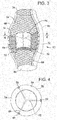
Figure 3 represents an oblique, partly cross-sectional view of another embodiment of the invention; and -
Figure 4 represents a cross-sectional view across line 4-4 of the embodiment shown inFigure 3 . - A main aspect of the present invention is the introduction of several novel designs for an implantable prosthetic valve. Another aspect of the present invention is the disclosure of several manufacturing methods for implantable prosthetic valves in accordance with the present invention. A further aspect of the present invention is the provision of novel deployment and positioning techniques suitable for the valve of the present invention.
- Basically the implantable prosthetic valve of the present invention comprises a leaflet-valve assembly, preferably tricuspid but not limited to tricuspid valves only, consisting of a conduit having an inlet end and an outlet, made of pliant material arranged so as to present collapsible walls at the outlet. The valve assembly is mounted on a support structure or frame such as a stent adapted to be positioned at a target location within the body duct and deploy the valve assembly by the use of deploying means, such as a balloon catheter or similar devices. In embodiments suitable for safe and convenient percutaneous positioning and deployment the annular frame is able to be posed in two positions, a crimped position where the conduit passage cross-section presented is small so as to permit advancing the device towards its target location, and a deployed position where the frame is radial extended by forces exerted from within (by deploying means) so as to provide support against the body duct wall, secure the valve in position and open itself so as to allow flow through the conduit.
- The valve assembly can be made from biological matter, such as a natural tissue, pericardial tissue or other biological tissue. Alternatively, the valve assembly may be made form biocompatible polymers or similar materials. Homograph biological valves need occasional replacement (usually within 5 to 14 years), and this is a consideration the surgeon must take into account when selecting the proper valve implant according to the patient type. Mechanical valves, which have better durability qualities, carry the associated risk of long-term anticoagulation treatment.
- The frame can be made from shape memory alloys such as nickel titanium (nickel titanium shape memory alloys, or NiTi, as marketed, for example, under the brand name Nitinol), or other biocompatible metals. The percutaneously implantable embodiment of the implantable valve of the present invention has to be suitable for crimping into a narrow configuration for positioning and expandable to a wider, deployed configuration so as to anchor in position in the desired target location.
- The support stent is preferably annular, but may be provided in other shapes too, depending on the cross-section shape of the desired target location passage.
- Manufacturing of the implantable prosthetic valve of the present invention can be done in various methods, by using pericardium or, for example, by using artificial materials made by dipping, injection, electrospinning, rotation, ironing, or pressing.
- The attachment of the valve assembly to the support stent can be accomplished in several ways, such as by sewing it to several anchoring points on the support frame or stent, or riveting it, pinning it, adhering it, or welding it, to provide a valve assembly that is cast or molded over the support frame or stent, or use any other suitable way of attachment.
- To prevent leakage from the inlet it is optionally possible to roll up some slack wall of the inlet over the edge of the frame so as to present rolled-up sleeve-like portion at the inlet.
- Furthermore, floating supports may be added to enhance the stability of the device and prevent it from turning inside out.
- An important aspect of certain embodiments of the present invention is the provision of rigid support beams incorporated with the support stent that retains its longitudinal dimension while the entire support stent may be longitudinally or laterally extended.
- The aforementioned embodiments as well as other embodiments, manufacturing methods, different designs and different types of devices are discussed and explained below with reference to the accompanying drawings. Note that the drawings are only given for the purpose of understanding the present invention and presenting some preferred embodiments of the present invention, but this does in no way limit the scope of the present invention as defined in the appended claims.
-
Figures 1 and 2 illustrate a general tricuspid implantableprosthetic valve 10 in accordance with a preferred embodiment of the present invention, suitable for percutaneous deployment using an expandable stent or similar deploying means, shown in its deployed position.Valve 10 comprises avalve assembly 20 having aninlet 22 and anoutlet 24, the outlet walls consisting of collapsiblepliant leaflet material 26 that is arranged to collapse in a tricuspid arrangement.Valve assembly 20 is attached to anannular support stent 32, the one in this figure being a net-like frame designed to be adapted to crimp evenly so as to present a narrow configuration and be radially deployable so as to extend to occupy the passage at the target location for implantation in a body duct. Support beams 34 are provided onannular support stent 32 to provide anchorage tovalve assembly 20. Support beams 34 are optionally provided withbores 36 to allow stitching ofvalve assembly 20 to supportbeams 34 by thread, wire, or other attachment means. - The
proximal portion 38 ofsupport stent 32 is snuggly fit or fastened to the proximal portion ofvalve assembly 20 so that any flow is only intoinlet 22. Optionally the radial sections of eachleaflet 26 is closed by stitching, gluing or other means tonarrow outlet 24. Thedistal portion 42 ofsupport stent 32 is narrower thanproximal portion 38. The combination of the effect on flow characteristics due to the narrowing ofsupport stent 32 and the narrowing ofoutlet 24 is sufficient to engender the desired effect or flow characteristics, namely, non-laminar retrograde flow that will assist in the closing ofleaflets 26. - Another embodiment of the invention is shown in
Figures 3 and 4 . Aprosthetic valve 50 comprises avalve assembly 52 positioned within asupport stent 54. The proximal 56 and distal 58 portions ofsupport stent 54 are narrow as compared to the mid-portion 60 ofsupport stent 54, wherevalve assembly 52 is positioned. Within support stent mid-portion 60valve assembly 52 is preferably positioned co-axially and at a small distance, for example, from 0.5 to 3 cm, from theinterior surface 64 ofsupport stent 54.Valve assembly 52 is attached by connectingmembrane 66 to stent supports 68, which optimally have holes orprojections 70 to anchor saidmembranes 66. Any annular space betweeninterior surface 64 andvalve assembly 54 is filled with appropriate material to prevent flow aroundvalve assembly 54. Valve leaflets are shown in closed 72 and open 74 positions. -
Valve assembly 54 is shown in a closed position whereinleaflets 70 inhibit flow. - The effective cross-sectional area of
valve assembly 54 will preferably be from about 40 to 80% of the cross-sectional area acrosssupport stent midsection 60. - The preferred embodiments representing an implantable prosthetic valve in accordance with the present invention are relatively easy to manufacture as they are generally flat throughout most of the production process and only at the final stage of mounting the other elements of the valve assembly on the support frame, a three dimensional form is established.
- A typical size of an aortic prosthetic valve is from about 19 to about 26 mm in diameter. A maximal size of a catheter inserted into the femoral artery should be no more than 9 mm in diameter. The present invention introduces a device, which has the ability to change its diameter from about 4 mm to about 26 mm. Artificial valves are not new; however, artificial valves in accordance with the present invention posses the ability to change shape and size for the purpose of delivery and as such are novel. These newly designed valves require new manufacturing methods and technical inventions and improvements, some of which were described herein.
- As mentioned earlier, the material of which the valve is made from can be either biological or artificial. In any case new technologies are needed to create such a valve.
- To attach the valve to the body, the blood vessels determine the size during delivery, and the requirements for it to work efficiently, there is a need to mount it on a collapsible construction which can be crimped to a small size, be expanded to a larger size, and be strong enough to act as a support for the valve function. This construction, which is in somewhat similar to a large "stent", can be made of different materials such as Nitinol, biocompatible stainless steel, polymeric material or a combination of all. Special requirement for the stent are a subject of some of the embodiments discussed herein.
- The mounting of the valve onto a collapsible stent is a new field of problems. New solutions to this problem are described herein.
- Another major aspect of the design of the valve of the present invention is the attachment to the body.
- In the traditional procedure the valve is sutured in place by a complicated suturing procedure. In the case of the percutaneous procedure there is no direct access to the implantation site therefore different attachment techniques are needed.
- Another new problem that is dealt herein is the delivery procedure, which is new and unique. Positioning of the device in the body in an accurate location and orientation requires special marking and measuring methods of the device and surgical site as was disclosed herein.
- Artificial polymer valves require special treatment and special conditions when kept on a shelf, as well as a special sterilization procedure. One of the consequences of the shelf treatment is the need to crimp the valve during the implantation procedure. A series of devices and inventions to allow the crimping procedure are disclosed herein.
- One or more embodiments may be defined in accordance with the following clauses:
- 1. A valve prosthesis device suitable for implantation in corporeal ducts, the device comprising: a support stent, and a valve assembly comprising a flexible conduit having an inlet end and an outlet end, wherein when flow is allowed to pass through the valve prosthesis device from the inlet to the outlet, the valve assembly is kept in an open position; wherein a reverse flow is prevented as the collapsible slack portions of the valve assembly collapse inwardly providing blockage to the reverse flow; and where the device is configured so that retrograde flow will be altered from laminar flow and directed towards the leaflets to effect closing.
- 2. The valve prosthesis device of Clause 1, wherein the support stent comprises a deployable construction adapted to be initially crimped in a narrow configuration suitable for catheterization through the body duct to a target location and adapted to be deployed by exerting substantially radial forces from within by means of a deployment device to a deployed state in the target location
- 3. The valve prosthesis device of Clause 1, wherein the support stent is provided with a plurality of longitudinally rigid support beams of fixed length.
- 4. The valve prosthesis device of Clause 1, wherein the valve assembly comprises pliant material attached to the support beams and provides collapsible slack portions of the conduit at the outlet.
- 5. The valve prosthesis of Clause 1, wherein the device is configured so that an artificial sinus is formed adjacent to the valve assembly.
- 6. The valve prosthesis of Clause 1, wherein the retrograde flow will be substantially non-laminar.
- 7. A valve prosthesis device suitable for implantation in corporeal ducts, the device comprising:
- a support stent, comprised of a deployable construction adapted to be initially crimped in a narrow configuration suitable for catheterization through the body duct to a target location and adapted to be deployed by exerting substantially radial forces from within by means of a deployment device to a deployed state in the target location, the support stent provided with a plurality of longitudinally rigid support beams of fixed length; and a valve assembly comprising a flexible conduit having an inlet end and an outlet, made of pliant material attached to the support beams providing collapsible slack portions of the conduit at the outlet, wherein when flow is allowed to pass through the valve prosthesis device from the inlet to the outlet, the valve assembly is kept in an open position, wherein a reverse flow is prevented as the collapsible slack portions of the valve assembly collapse inwardly providing blockage to the reverse flow, and wherein the device is configured so that retrograde flow will be altered from laminar flow and directed towards the leaflets to effect closing.
- 8. The valve prosthesis device of Clause 7, wherein the support stent comprises an annular frame.
- 9. The valve prosthesis device of Clause 7, wherein said valve assembly has a tricuspid configuration.
- 10. The valve prosthesis device of Clause 7, wherein said valve assembly is made from biocompatible material.
- 11. The valve prosthesis device of
Clause 10, wherein the valve assembly is made from pericardial tissue, or other biological tissue. - 12. The valve prosthesis device of Clause 7, wherein said valve assembly is made from biocompatible polymers.
- 13. The valve prosthesis device of Clause 12, wherein the valve assembly is made from materials selected from polyurethane and polyethylene terephthalate.
- 14. The valve prosthesis device of Clause 13, wherein said valve assembly comprises a main body made from polyethylene terephthalate and leaflets made from polyurethane.
- 15. The valve prosthesis device of Clause 7, wherein said support stent is made from nickel titanium.
- 16. The valve prosthesis device of Clause 7, wherein the support beams are substantially equidistant and substantially parallel so as to provide anchorage for the valve assembly.
- 17. The valve prosthesis device of Clause 7, wherein the support beams are provided with bores so as to allow stitching or tying of the valve assembly to the beams.
- 18. The valve prosthesis device of Clause 7, wherein the support beams are chemically adhered to the support stent.
- 19. The valve prosthesis device of Clause 7, wherein said valve assembly is riveted to the support beams.
- 20. The valve prosthesis device of Clause 7, wherein said valve assembly is stitched to the support beams.
- 21. The valve prosthesis device of Clause 7, wherein said beams are manufactured by injection using a mold, or by machining.
- 22. The valve prosthesis device of Clause 7, wherein said valve assembly is rolled over the support stent at the inlet.
- 23. The valve prosthesis device of Clause 7, wherein said valve device is manufactured using forging or dipping techniques.
- 24. The valve prosthesis device of Clause 7, wherein said valve assembly leaflets are longer than needed to exactly close the outlet, thus when they are in the collapsed state substantial portions of the leaflets fall on each other creating better sealing.
- 25. The valve prosthesis device of Clause 7, wherein said valve assembly is made from a coiled polymer, coated by a coating layer of the same polymer.
- 26. The valve prosthesis device of Clause 25, wherein said polymer is polyurethane.
- 27. The valve prosthesis device of Clause 7, wherein the support stent is provided with heavy metal markers so as to enable tracking and determining the valve device position and orientation.
- 28. The valve prosthesis device of Clause 27, wherein the heavy metal markers are selected from the group consisting of gold, platinum-iridium, and tantalum.
- 29. The valve prosthesis device of Clause 7, wherein the valve assembly leaflets are provided with radio-opaque material at the outlet, so as to help tracking the valve device operation in vivo.
- 30. The valve prosthesis device of Clause 29, wherein said radio-opaque material comprises gold thread.
- 31. The valve prosthesis device of Clause 7, wherein the diameter of said support stent, when fully deployed is in the range of from about 19 to about 26 mm.
- 32. The valve prosthesis device of Clause 7, wherein the diameter of said support stent may be expanded from about 4 to about 26mm.
- 33. The valve prosthesis device of Clause 7, wherein the support beams are provided with bores and wherein the valve assembly is attached to the support beams by means of U-shaped rigid members that are fastened to the valve assembly and that are provided with extruding portions that fit into matching bores on the support beams.
- 34. The valve prosthesis device of Clause 7, wherein the support beams comprise rigid support beams in the form of frame construction, and the valve assembly pliant material is inserted through a gap in the frame and a fastening rod is inserted through a pocket formed between the pliant material and the frame and holds the valve in position.
- 35. The valve prosthesis device of Clause 7, wherein the main body of the valve assembly is made from coiled wire coated with a coating material.
- 36. The valve prosthesis device of Clause 35, wherein the coiled wire and the coating material is made from polyurethane.
- 37. The valve prosthesis device of Clause 7, wherein a strengthening wire is interlaced in the valve assembly at the outlet of the conduit so as to define a fault line about which the collapsible slack portion of the valve assembly may flap.
- 38. The valve prosthesis device of Clause 37, wherein the strengthening-wire is made from nickel titanium alloy.
- 39. A valve prosthesis device suitable for implantation in corporeal ducts, the device comprising a main conduit body having an inlet and an outlet and pliant leaflets attached at the outlet so that when flow passes through the conduit from the inlet to the outlet the leaflets are in an open position allowing the flow to exit the outlet, and when the flow is reversed the leaflets collapse so as to block the outlet, wherein the main body is made from polyethylene terephtalate and collapsible leaflets are made form polyurethane and wherein the device is configured so that retrograde flow will be altered from laminar flow and directed towards the leaflets to effect closing.
- 40. The valve prosthesis device of Clause 39, wherein support beams made from polyurethane are provided on the main body and wherein the leaflets are attached to the main body at the support beams.
- 41. The valve prosthesis device of Clause 39, wherein said support beams are chemically adhered to the main body.
- 42. A valve prosthesis device suitable for implantation in corporeal ducts, the device comprising: a support stent, comprised of a deployable construction adapted to be initially crimped in a narrow configuration suitable for catheterization through the body duct to a target location and adapted to be deployed by exerting substantially radial forces from within by means of a deployment device to a deployed state in the target location, the support stent provided with a plurality of longitudinally rigid support beams of fixed length; a valve assembly comprising a flexible conduit having an inlet end and an outlet, made of pliant material attached to the support beams providing collapsible slack portions of the conduit at the outlet; and substantially equidistant rigid support beams interlaced or attached to the slack portion of the valve assembly material, arranged longitudinally, wherein the device is configured so that retrograde flow will be altered from laminar flow and directed towards the leaflets to effect closing.
- 43. A valve prosthesis device suitable for implantation in corporeal ducts, the device comprising:
- an expandable support frame, the support frame provided with a plurality of longitudinally rigid support beams of fixed length; and a valve assembly comprising a flexible conduit having an inlet end and an outlet, made of pliant material attached to the support beams providing collapsible slack portions of the conduit at the outlet, wherein when flow is allowed to pass through the valve prosthesis device from the inlet to the outlet, the valve assembly is
- kept in an open position, wherein a reverse flow is prevented as the collapsible slack portions of the valve assembly collapse inwardly providing blockage to the reverse flow, and wherein the device is configured so that retrograde flow will be altered from laminar flow and
- directed towards the leaflets to effect closing.
- 44. The valve prosthetic device of Clause 43, wherein the expandable support frame comprises a deployable construction adapted to be initially crimped in a narrow configuration suitable for catheterization through the corporeal duct to a target location and adapted to be deployed by exerting substantially radial forces from within by means of a deployment device to a deployed state in the target location.
- 45. The valve prosthetic device of Clause 43, wherein the support beams have aU-shaped cross section.
- 46. The valve prosthetic device of Clause 45, wherein a holder is used to secure the pliant material to the support beams.
- 47. The valve prosthetic device of Clause 43, wherein the support frame comprises three segments that form a circular assembly when assembled.
- 48. The valve prosthetic device of Clause 43, wherein the support beams point inwardly with respect to a central longitudinal axis of the device.
- 49. The valve prosthetic device of Clause 47, wherein the support beams point outwardly with respect to a central longitudinal axis of the device.
- 50. The valve prosthetic device of Clause 43, further provided with a restricting tapered housing, for housing it in a crimped state.
- 51. The valve prosthetic device of Clause 43, wherein hooks are provided to secure the device in position after it is deployed.
- 52. The valve prosthetic device of Clause 43, wherein the support beams comprise longitudinal bars having a narrow slit used as the commissural attachment so that extensions the pliant material are tightly inserted through it.
- 53. The valve prosthetic device of
Clause 52, wherein the extensions of the pliant material are wrapped about rigid bars serving as anchorage means. - 54. The valve prosthetic device of Clause 53, wherein extensions of the pliant material are sutured to each other at the rigid bars.
- 55. The valve prosthetic device of
Clause 54, wherein a bottom portion of the pliant material is attached to the inlet. - 56. The valve prosthetic device of Clause 43, wherein the support beams are each provided with a rounded pole, forming a loop through which the pliant material is inserted.
- 57. The valve prosthetic device of Clause 43, wherein the pliant material is provided with longitudinal bars attached to the pliant material at positions assigned for attachment to the support frame, in order to prevent localized stress from forming.
- 58. The valve prosthetic device of Clause 43, further provided with longitudinal bars having protrusions that are inserted in bores in the pliant material, a sheet of PET and through bores provided on the support beams.
- 59. The valve prosthetic device of Clause 43, wherein the pliant material is sutured leaving the slack portions free of sutures.
- 60. The valve prosthetic device of Clause 43, wherein a connecting member with a split portion is used to connect leaflets of the pliant material to the support beams, the split connecting member compressing the pliant material in position.
- 61. The valve prosthetic device of
Clause 60, wherein a portion of the connecting member is perpendicular to the split portion. - 62. The valve prosthetic device of Clause 43, wherein the support frame is provided with metallic members coupled to the stent and rigid members are positioned on two opposite sides of the metallic member and held against each other, holding a portion of the pliant material between them, sutured, the metallic members wrapped with PET.
- 63. The valve prosthetic device of Clause 3, wherein the device is further provided with spring to reduce wear of the pliant material.
- 64. The valve prosthetic device of Clause 63, wherein the spring is provided with a spiral.
- 65. The valve prosthetic device of Clause 63, wherein the spring is made from stainless steel.
- 66. The valve prosthetic device of Clause 63, wherein the spring is attached to slots provided on the support frame.
- 67. The valve prosthetic device of Clause 43, wherein the pliant material is sutured to the support frame forming pockets.
- 68. The valve prosthetic device of Clause 67, wherein attachment bars are provided on the stent support at a portion of the stent close to the outlet, on which the pliant material is coupled to, and wherein the pliant material is attached circumferentially to the inlet, leaving slack pliant material.
- 69. The valve prosthetic device of Clause 43, wherein the outlet is tapered with respect to the inlet.
- 70. The valve prosthetic device of Clause 69, wherein the support frame at the outlet is wider in diameter than the pliant material forming the outlet.
- 71. The valve prosthetic device of Clause 43, wherein the pliant material is reinforced using PET.
- 72. The valve prosthetic device of Clause 43, wherein the support frame is a tube having an inner wall, having sinusoidal fold lines, wherein the pliant material is sutured to the inner wall of the tube along suture lines.
- 73. The valve prosthetic device of
Clause 72, wherein additional piece of PET is added below the suture lines. - 74. The valve prosthetic device of Clause 43, wherein the device is incorporated with an angioplasty balloon.
- 75. The valve prosthetic device of
Clause 74, wherein the balloon has a central longitudinal axis that runs along a flow path through the device, and a perimeter, the balloon comprising four inflatable portions, one portion located along a central axis and the other three located on the perimeter, the pliant material in the form of leaflets is distributed about the perimeter. - It should be clear that the description of the embodiments and attached Figures set forth in this specification serves only for a better understanding of the invention, without limiting its scope as covered by the following Claims.
- It should also be clear that a person skilled in the art, after reading the present specification could make adjustments or amendments to the attached Figures and above described embodiments that would still be covered by the following Claims.
Claims (15)
- A prosthetic heart valve, comprising:an expandable support stent having first and second end portions, wherein the support stent is configured to be radially expandable from a first configuration to a second configuration;a valve assembly having an inlet portion, an outlet portion, and a plurality of leaflets, wherein the valve assembly is supported in the support stent; anda connecting membrane extending radially inwardly from the support stent to the valve assembly, wherein the support stent and the valve assembly are connected to the connecting membrane.
- The prosthetic heart valve of claim 1, wherein the connecting membrane has an inner edge connected to the valve assembly and an outer edge connected to the support stent.
- The prosthetic heart valve of claim 2, wherein the outer edge of the connecting membrane is connected to the support stent with stitching.
- The prosthetic heart valve of any preceding claim, wherein an annular space is defined between the inner surface of the support stent and the outer surface of the valve assembly, and sealing material is disposed in the annular spaced to prevent blood from flowing around the valve assembly.
- The prosthetic heart valve of any preceding claim, wherein the first configuration is a crimped configuration and the second configuration is a deployed configuration, and the valve assembly is spaced radially inwardly from the support stent by 0.5 cm to 3 cm when the support stent is in the deployed configuration.
- The prosthetic heart valve of any preceding claim, wherein the support stent further comprises a mid-portion disposed axially between the first and second end portions and comprises a longitudinal axis extending from the first end portion to the second end portion, the support stent and the valve assembly each have a cross-sectional area taken in a plane that is perpendicular to the longitudinal axis of the support stent at the mid-portion of the support stent, and the cross-sectional area of the valve assembly is 40-80 percent of the cross-sectional area of the support stent when the support stent is in the deployed configuration.
- The prosthetic heart valve of any preceding claim, wherein the support stent further comprises a mid-portion disposed axially between the first and second end portions, and the mid-portion of the support stent is radially larger than the first end second end portions when the support stent is in the deployed configuration.
- The prosthetic heart valve of any preceding claim, wherein the connecting membrane extends from the inlet portion to the outlet portion of the valve assembly.
- The prosthetic heart valve of any preceding claim, wherein the inlet portion and the outlet portion of the valve assembly are spaced radially inwardly of the support stent by the connecting membrane.
- The prosthetic heart valve of any preceding claim, wherein the leaflets form a plurality of commissures and the connecting membrane comprises a connecting membrane positioned adjacent each commissure, each connecting membrane extending from the support stent to an adjacent commissure.
- A prosthetic heart valve, comprising:an expandable support stent having a first end portion and a second end portion, wherein the support stent is configured to be radially expandable from a first, crimped configuration for catheterization into a patient's body to a second, expanded configuration;a valve assembly having an inlet end, an outlet end, and a plurality of leaflets, wherein the valve assembly is supported in the support stent, wherein the leaflets are configured to permit blood to flow through the valve assembly in a direction from the first end portion to the second end portion of the frame and block the flow of blood in the reverse direction; andwherein an annular space is defined between an interior of the support stent and the valve assembly at the inlet end of the valve assembly when the support stent is in the second configuration.
- The prosthetic heart valve of claim 12, further comprising sealing material disposed in the annular space to prevent blood from flowing around the valve assembly.
- The prosthetic heart valve of claim 11 or 12, further comprising a connecting membrane extending radially inwardly from the support stent to the valve assembly, wherein the support stent and the valve assembly are connected to the connecting membrane.
- The prosthetic heart valve of any of claims 11 to 13, wherein the support stent tapers from the first end portion to the second end portion.
- The prosthetic heart valve of any of claim 11 to 14, wherein the annular space extends from the inlet end to the outlet end of the valve assembly.
Applications Claiming Priority (3)
| Application Number | Priority Date | Filing Date | Title |
|---|---|---|---|
| US10/677,947 US20050075725A1 (en) | 2003-10-02 | 2003-10-02 | Implantable prosthetic valve with non-laminar flow |
| EP04785349.4A EP1667614B2 (en) | 2003-10-02 | 2004-10-01 | Implantable prosthetic valve with non-laminar flow |
| PCT/US2004/032388 WO2005034812A1 (en) | 2003-10-02 | 2004-10-01 | Implantable prosthetic valve with non-laminar flow |
Related Parent Applications (2)
| Application Number | Title | Priority Date | Filing Date |
|---|---|---|---|
| EP04785349.4A Division-Into EP1667614B2 (en) | 2003-10-02 | 2004-10-01 | Implantable prosthetic valve with non-laminar flow |
| EP04785349.4A Division EP1667614B2 (en) | 2003-10-02 | 2004-10-01 | Implantable prosthetic valve with non-laminar flow |
Publications (2)
| Publication Number | Publication Date |
|---|---|
| EP3156007A1 true EP3156007A1 (en) | 2017-04-19 |
| EP3156007B1 EP3156007B1 (en) | 2020-11-25 |
Family
ID=34393839
Family Applications (2)
| Application Number | Title | Priority Date | Filing Date |
|---|---|---|---|
| EP04785349.4A Active EP1667614B2 (en) | 2003-10-02 | 2004-10-01 | Implantable prosthetic valve with non-laminar flow |
| EP16191929.5A Active EP3156007B1 (en) | 2003-10-02 | 2004-10-01 | Implantable prosthetic valve with non-laminar flow |
Family Applications Before (1)
| Application Number | Title | Priority Date | Filing Date |
|---|---|---|---|
| EP04785349.4A Active EP1667614B2 (en) | 2003-10-02 | 2004-10-01 | Implantable prosthetic valve with non-laminar flow |
Country Status (6)
| Country | Link |
|---|---|
| US (6) | US20050075725A1 (en) |
| EP (2) | EP1667614B2 (en) |
| JP (2) | JP4852421B2 (en) |
| AU (1) | AU2004279385B2 (en) |
| CA (1) | CA2541065A1 (en) |
| WO (1) | WO2005034812A1 (en) |
Cited By (13)
| Publication number | Priority date | Publication date | Assignee | Title |
|---|---|---|---|---|
| US10940001B2 (en) | 2012-05-30 | 2021-03-09 | Neovasc Tiara Inc. | Methods and apparatus for loading a prosthesis onto a delivery system |
| US11311376B2 (en) | 2019-06-20 | 2022-04-26 | Neovase Tiara Inc. | Low profile prosthetic mitral valve |
| US11357622B2 (en) | 2016-01-29 | 2022-06-14 | Neovase Tiara Inc. | Prosthetic valve for avoiding obstruction of outflow |
| US11389291B2 (en) | 2013-04-04 | 2022-07-19 | Neovase Tiara Inc. | Methods and apparatus for delivering a prosthetic valve to a beating heart |
| US11413139B2 (en) | 2011-11-23 | 2022-08-16 | Neovasc Tiara Inc. | Sequentially deployed transcatheter mitral valve prosthesis |
| US11419720B2 (en) | 2010-05-05 | 2022-08-23 | Neovasc Tiara Inc. | Transcatheter mitral valve prosthesis |
| US11464631B2 (en) | 2016-11-21 | 2022-10-11 | Neovasc Tiara Inc. | Methods and systems for rapid retraction of a transcatheter heart valve delivery system |
| US11491006B2 (en) | 2019-04-10 | 2022-11-08 | Neovasc Tiara Inc. | Prosthetic valve with natural blood flow |
| US11497602B2 (en) | 2012-02-14 | 2022-11-15 | Neovasc Tiara Inc. | Methods and apparatus for engaging a valve prosthesis with tissue |
| US11602429B2 (en) | 2019-04-01 | 2023-03-14 | Neovasc Tiara Inc. | Controllably deployable prosthetic valve |
| US11737872B2 (en) | 2018-11-08 | 2023-08-29 | Neovasc Tiara Inc. | Ventricular deployment of a transcatheter mitral valve prosthesis |
| US11779742B2 (en) | 2019-05-20 | 2023-10-10 | Neovasc Tiara Inc. | Introducer with hemostasis mechanism |
| US11793640B2 (en) | 2017-08-25 | 2023-10-24 | Neovasc Tiara Inc. | Sequentially deployed transcatheter mitral valve prosthesis |
Families Citing this family (281)
| Publication number | Priority date | Publication date | Assignee | Title |
|---|---|---|---|---|
| EP0850607A1 (en) | 1996-12-31 | 1998-07-01 | Cordis Corporation | Valve prosthesis for implantation in body channels |
| US6254564B1 (en) | 1998-09-10 | 2001-07-03 | Percardia, Inc. | Left ventricular conduit with blood vessel graft |
| DE10010074B4 (en) | 2000-02-28 | 2005-04-14 | Fraunhofer-Gesellschaft zur Förderung der angewandten Forschung e.V. | Device for fastening and anchoring heart valve prostheses |
| DE10010073B4 (en) * | 2000-02-28 | 2005-12-22 | Fraunhofer-Gesellschaft zur Förderung der angewandten Forschung e.V. | Anchoring for implantable heart valve prostheses |
| US6454799B1 (en) | 2000-04-06 | 2002-09-24 | Edwards Lifesciences Corporation | Minimally-invasive heart valves and methods of use |
| US6602286B1 (en) | 2000-10-26 | 2003-08-05 | Ernst Peter Strecker | Implantable valve system |
| US6733525B2 (en) | 2001-03-23 | 2004-05-11 | Edwards Lifesciences Corporation | Rolled minimally-invasive heart valves and methods of use |
| FR2828263B1 (en) | 2001-08-03 | 2007-05-11 | Philipp Bonhoeffer | DEVICE FOR IMPLANTATION OF AN IMPLANT AND METHOD FOR IMPLANTATION OF THE DEVICE |
| US6893460B2 (en) | 2001-10-11 | 2005-05-17 | Percutaneous Valve Technologies Inc. | Implantable prosthetic valve |
| US8308797B2 (en) | 2002-01-04 | 2012-11-13 | Colibri Heart Valve, LLC | Percutaneously implantable replacement heart valve device and method of making same |
| US6752828B2 (en) | 2002-04-03 | 2004-06-22 | Scimed Life Systems, Inc. | Artificial valve |
| US6945957B2 (en) | 2002-12-30 | 2005-09-20 | Scimed Life Systems, Inc. | Valve treatment catheter and methods |
| US20050107871A1 (en) * | 2003-03-30 | 2005-05-19 | Fidel Realyvasquez | Apparatus and methods for valve repair |
| US20050075725A1 (en) | 2003-10-02 | 2005-04-07 | Rowe Stanton J. | Implantable prosthetic valve with non-laminar flow |
| US7854761B2 (en) | 2003-12-19 | 2010-12-21 | Boston Scientific Scimed, Inc. | Methods for venous valve replacement with a catheter |
| US8128681B2 (en) | 2003-12-19 | 2012-03-06 | Boston Scientific Scimed, Inc. | Venous valve apparatus, system, and method |
| JP4975609B2 (en) * | 2004-02-27 | 2012-07-11 | エーオーテックス, インコーポレイテッド | Prosthetic heart valve delivery system and method |
| WO2005087140A1 (en) | 2004-03-11 | 2005-09-22 | Percutaneous Cardiovascular Solutions Pty Limited | Percutaneous heart valve prosthesis |
| US7276078B2 (en) * | 2004-06-30 | 2007-10-02 | Edwards Lifesciences Pvt | Paravalvular leak detection, sealing, and prevention |
| US7566343B2 (en) | 2004-09-02 | 2009-07-28 | Boston Scientific Scimed, Inc. | Cardiac valve, system, and method |
| AU2004324043A1 (en) * | 2004-10-02 | 2006-04-20 | Christoph Hans Huber | Methods and devices for repair or replacement of heart valves or adjacent tissue without the need for full cardiopulmonary support |
| US20060095117A1 (en) * | 2004-11-03 | 2006-05-04 | Popelar Carl F | Apparatus and method for temporarily clamping a tubular graft to a prosthetic cardiac valve |
| DE102005003632A1 (en) | 2005-01-20 | 2006-08-17 | Fraunhofer-Gesellschaft zur Förderung der angewandten Forschung e.V. | Catheter for the transvascular implantation of heart valve prostheses |
| US20060173490A1 (en) | 2005-02-01 | 2006-08-03 | Boston Scientific Scimed, Inc. | Filter system and method |
| US7854755B2 (en) | 2005-02-01 | 2010-12-21 | Boston Scientific Scimed, Inc. | Vascular catheter, system, and method |
| US7878966B2 (en) | 2005-02-04 | 2011-02-01 | Boston Scientific Scimed, Inc. | Ventricular assist and support device |
| US7670368B2 (en) | 2005-02-07 | 2010-03-02 | Boston Scientific Scimed, Inc. | Venous valve apparatus, system, and method |
| US7780722B2 (en) | 2005-02-07 | 2010-08-24 | Boston Scientific Scimed, Inc. | Venous valve apparatus, system, and method |
| US7867274B2 (en) | 2005-02-23 | 2011-01-11 | Boston Scientific Scimed, Inc. | Valve apparatus, system and method |
| US7722666B2 (en) | 2005-04-15 | 2010-05-25 | Boston Scientific Scimed, Inc. | Valve apparatus, system and method |
| US7914569B2 (en) * | 2005-05-13 | 2011-03-29 | Medtronics Corevalve Llc | Heart valve prosthesis and methods of manufacture and use |
| EP1895941A1 (en) * | 2005-05-20 | 2008-03-12 | The Cleveland Clinic Foundation | Apparatus and methods for repairing the function of a diseased valve and method for making same |
| US8012198B2 (en) | 2005-06-10 | 2011-09-06 | Boston Scientific Scimed, Inc. | Venous valve, system, and method |
| US7569071B2 (en) | 2005-09-21 | 2009-08-04 | Boston Scientific Scimed, Inc. | Venous valve, system, and method with sinus pocket |
| DE102005051849B4 (en) * | 2005-10-28 | 2010-01-21 | JenaValve Technology Inc., Wilmington | Device for implantation and attachment of heart valve prostheses |
| DE102005052628B4 (en) * | 2005-11-04 | 2014-06-05 | Jenavalve Technology Inc. | Self-expanding, flexible wire mesh with integrated valvular prosthesis for the transvascular heart valve replacement and a system with such a device and a delivery catheter |
| US8092520B2 (en) | 2005-11-10 | 2012-01-10 | CardiAQ Technologies, Inc. | Vascular prosthesis connecting stent |
| US20070213813A1 (en) | 2005-12-22 | 2007-09-13 | Symetis Sa | Stent-valves for valve replacement and associated methods and systems for surgery |
| US7799038B2 (en) | 2006-01-20 | 2010-09-21 | Boston Scientific Scimed, Inc. | Translumenal apparatus, system, and method |
| US8147541B2 (en) | 2006-02-27 | 2012-04-03 | Aortx, Inc. | Methods and devices for delivery of prosthetic heart valves and other prosthetics |
| US7749266B2 (en) * | 2006-02-27 | 2010-07-06 | Aortx, Inc. | Methods and devices for delivery of prosthetic heart valves and other prosthetics |
| US7648527B2 (en) * | 2006-03-01 | 2010-01-19 | Cook Incorporated | Methods of reducing retrograde flow |
| US8075615B2 (en) | 2006-03-28 | 2011-12-13 | Medtronic, Inc. | Prosthetic cardiac valve formed from pericardium material and methods of making same |
| EP1849440A1 (en) * | 2006-04-28 | 2007-10-31 | Younes Boudjemline | Vascular stents with varying diameter |
| US8585594B2 (en) | 2006-05-24 | 2013-11-19 | Phoenix Biomedical, Inc. | Methods of assessing inner surfaces of body lumens or organs |
| JP2009540954A (en) * | 2006-06-20 | 2009-11-26 | エーオーテックス, インコーポレイテッド | Prosthetic valve implantation site preparation technology |
| EP2035723A4 (en) | 2006-06-20 | 2011-11-30 | Aortx Inc | Torque shaft and torque drive |
| CA2657442A1 (en) | 2006-06-20 | 2007-12-27 | Aortx, Inc. | Prosthetic heart valves, support structures and systems and methods for implanting the same |
| AU2007260951A1 (en) * | 2006-06-21 | 2007-12-27 | Aortx, Inc. | Prosthetic valve implantation systems |
| US9408607B2 (en) | 2009-07-02 | 2016-08-09 | Edwards Lifesciences Cardiaq Llc | Surgical implant devices and methods for their manufacture and use |
| AU2007281553B2 (en) | 2006-07-31 | 2013-09-19 | Edwards Lifesciences Cardiaq Llc | Sealable endovascular implants and methods for their use |
| US9585743B2 (en) | 2006-07-31 | 2017-03-07 | Edwards Lifesciences Cardiaq Llc | Surgical implant devices and methods for their manufacture and use |
| US8414643B2 (en) | 2006-09-19 | 2013-04-09 | Medtronic Ventor Technologies Ltd. | Sinus-engaging valve fixation member |
| US11304800B2 (en) | 2006-09-19 | 2022-04-19 | Medtronic Ventor Technologies Ltd. | Sinus-engaging valve fixation member |
| US8834564B2 (en) | 2006-09-19 | 2014-09-16 | Medtronic, Inc. | Sinus-engaging valve fixation member |
| WO2008046092A2 (en) * | 2006-10-13 | 2008-04-17 | Creighton University | Implantable valve prosthesis |
| DE102006062384A1 (en) * | 2006-12-22 | 2008-06-26 | Aesculap Ag & Co. Kg | Tubular vascular prosthesis for replacement of the ascending aorta |
| US8236045B2 (en) | 2006-12-22 | 2012-08-07 | Edwards Lifesciences Corporation | Implantable prosthetic valve assembly and method of making the same |
| US8133270B2 (en) | 2007-01-08 | 2012-03-13 | California Institute Of Technology | In-situ formation of a valve |
| US8105375B2 (en) * | 2007-01-19 | 2012-01-31 | The Cleveland Clinic Foundation | Method for implanting a cardiovascular valve |
| US7967853B2 (en) | 2007-02-05 | 2011-06-28 | Boston Scientific Scimed, Inc. | Percutaneous valve, system and method |
| US20080262593A1 (en) * | 2007-02-15 | 2008-10-23 | Ryan Timothy R | Multi-layered stents and methods of implanting |
| US9138315B2 (en) * | 2007-04-13 | 2015-09-22 | Jenavalve Technology Gmbh | Medical device for treating a heart valve insufficiency or stenosis |
| US7896915B2 (en) * | 2007-04-13 | 2011-03-01 | Jenavalve Technology, Inc. | Medical device for treating a heart valve insufficiency |
| FR2915678B1 (en) * | 2007-05-02 | 2010-04-16 | Lapeyre Ind Llc | MECHANICAL PROTHETIC CARDIAC VALVE |
| EP2150210B1 (en) * | 2007-05-15 | 2016-10-12 | JenaValve Technology, Inc. | Handle for manipulating a catheter tip, catheter system and medical insertion system for inserting a self-expandable heart valve stent |
| DE102007031148A1 (en) * | 2007-06-27 | 2009-01-08 | Aesculap Ag | aortic sinus |
| US8828079B2 (en) | 2007-07-26 | 2014-09-09 | Boston Scientific Scimed, Inc. | Circulatory valve, system and method |
| US9566178B2 (en) | 2010-06-24 | 2017-02-14 | Edwards Lifesciences Cardiaq Llc | Actively controllable stent, stent graft, heart valve and method of controlling same |
| US9814611B2 (en) | 2007-07-31 | 2017-11-14 | Edwards Lifesciences Cardiaq Llc | Actively controllable stent, stent graft, heart valve and method of controlling same |
| EP2219558B8 (en) * | 2007-08-21 | 2015-09-23 | Symetis SA | Stent-valves for valve replacement and associated systems for surgery |
| DE202008018589U1 (en) | 2007-09-26 | 2016-03-14 | St. Jude Medical, Inc. | Foldable heart valve prostheses |
| US9532868B2 (en) | 2007-09-28 | 2017-01-03 | St. Jude Medical, Inc. | Collapsible-expandable prosthetic heart valves with structures for clamping native tissue |
| WO2009045331A1 (en) | 2007-09-28 | 2009-04-09 | St. Jude Medical, Inc. | Two-stage collapsible/expandable prosthetic heart valves and anchoring systems |
| US8715337B2 (en) * | 2007-11-09 | 2014-05-06 | Cook Medical Technologies Llc | Aortic valve stent graft |
| EP4079261A1 (en) | 2007-12-14 | 2022-10-26 | Edwards Lifesciences Corporation | Leaflet attachment frame for a prosthetic valve |
| US7892276B2 (en) | 2007-12-21 | 2011-02-22 | Boston Scientific Scimed, Inc. | Valve with delayed leaflet deployment |
| US8157852B2 (en) | 2008-01-24 | 2012-04-17 | Medtronic, Inc. | Delivery systems and methods of implantation for prosthetic heart valves |
| JP5687070B2 (en) | 2008-01-24 | 2015-03-18 | メドトロニック,インコーポレイテッド | Stent for prosthetic heart valve |
| US8398704B2 (en) | 2008-02-26 | 2013-03-19 | Jenavalve Technology, Inc. | Stent for the positioning and anchoring of a valvular prosthesis in an implantation site in the heart of a patient |
| WO2011104269A1 (en) | 2008-02-26 | 2011-09-01 | Jenavalve Technology Inc. | Stent for the positioning and anchoring of a valvular prosthesis in an implantation site in the heart of a patient |
| US9044318B2 (en) | 2008-02-26 | 2015-06-02 | Jenavalve Technology Gmbh | Stent for the positioning and anchoring of a valvular prosthesis |
| US9168130B2 (en) * | 2008-02-26 | 2015-10-27 | Jenavalve Technology Gmbh | Stent for the positioning and anchoring of a valvular prosthesis in an implantation site in the heart of a patient |
| US8465540B2 (en) | 2008-02-26 | 2013-06-18 | Jenavalve Technology, Inc. | Stent for the positioning and anchoring of a valvular prosthesis |
| US8317858B2 (en) * | 2008-02-26 | 2012-11-27 | Jenavalve Technology, Inc. | Stent for the positioning and anchoring of a valvular prosthesis in an implantation site in the heart of a patient |
| US8313525B2 (en) * | 2008-03-18 | 2012-11-20 | Medtronic Ventor Technologies, Ltd. | Valve suturing and implantation procedures |
| JP5309207B2 (en) * | 2008-04-01 | 2013-10-09 | メドトロニック ヴァスキュラー インコーポレイテッド | Double wall stent system |
| US20090276040A1 (en) | 2008-05-01 | 2009-11-05 | Edwards Lifesciences Corporation | Device and method for replacing mitral valve |
| WO2009149462A2 (en) | 2008-06-06 | 2009-12-10 | Edwards Lifesciences Corporation | Low profile transcatheter heart valve |
| US8323335B2 (en) | 2008-06-20 | 2012-12-04 | Edwards Lifesciences Corporation | Retaining mechanisms for prosthetic valves and methods for using |
| WO2010008548A2 (en) | 2008-07-15 | 2010-01-21 | St. Jude Medical, Inc. | Collapsible and re-expandable prosthetic heart valve cuff designs and complementary technological applications |
| US8652202B2 (en) | 2008-08-22 | 2014-02-18 | Edwards Lifesciences Corporation | Prosthetic heart valve and delivery apparatus |
| US9314335B2 (en) | 2008-09-19 | 2016-04-19 | Edwards Lifesciences Corporation | Prosthetic heart valve configured to receive a percutaneous prosthetic heart valve implantation |
| US8287591B2 (en) * | 2008-09-19 | 2012-10-16 | Edwards Lifesciences Corporation | Transformable annuloplasty ring configured to receive a percutaneous prosthetic heart valve implantation |
| EP2367505B1 (en) | 2008-09-29 | 2020-08-12 | Edwards Lifesciences CardiAQ LLC | Heart valve |
| CA2739275C (en) | 2008-10-01 | 2017-01-17 | Impala, Inc. | Delivery system for vascular implant |
| US8690936B2 (en) | 2008-10-10 | 2014-04-08 | Edwards Lifesciences Corporation | Expandable sheath for introducing an endovascular delivery device into a body |
| JP5739823B2 (en) * | 2009-02-20 | 2015-06-24 | セント ジュード メディカル インコーポレイテッドSt. Jude Medical, Inc. | Apparatus and method for folding a prosthetic heart valve |
| CA2961053C (en) | 2009-04-15 | 2019-04-30 | Edwards Lifesciences Cardiaq Llc | Vascular implant and delivery system |
| US8468667B2 (en) * | 2009-05-15 | 2013-06-25 | Jenavalve Technology, Inc. | Device for compressing a stent |
| US8475522B2 (en) | 2009-07-14 | 2013-07-02 | Edwards Lifesciences Corporation | Transapical delivery system for heart valves |
| US9730790B2 (en) | 2009-09-29 | 2017-08-15 | Edwards Lifesciences Cardiaq Llc | Replacement valve and method |
| US20110313515A1 (en) | 2010-06-21 | 2011-12-22 | Arshad Quadri | Replacement heart valve |
| US8449599B2 (en) | 2009-12-04 | 2013-05-28 | Edwards Lifesciences Corporation | Prosthetic valve for replacing mitral valve |
| US8870950B2 (en) | 2009-12-08 | 2014-10-28 | Mitral Tech Ltd. | Rotation-based anchoring of an implant |
| US8795354B2 (en) | 2010-03-05 | 2014-08-05 | Edwards Lifesciences Corporation | Low-profile heart valve and delivery system |
| US8679404B2 (en) | 2010-03-05 | 2014-03-25 | Edwards Lifesciences Corporation | Dry prosthetic heart valve packaging system |
| WO2011111047A2 (en) | 2010-03-10 | 2011-09-15 | Mitraltech Ltd. | Prosthetic mitral valve with tissue anchors |
| EP2552356B1 (en) * | 2010-03-26 | 2019-03-13 | Thubrikar Aortic Valve Inc. | Valve component, frame component and prosthetic valve device including the same for implantation in a body lumen |
| US8652204B2 (en) | 2010-04-01 | 2014-02-18 | Medtronic, Inc. | Transcatheter valve with torsion spring fixation and related systems and methods |
| US11278406B2 (en) | 2010-05-20 | 2022-03-22 | Jenavalve Technology, Inc. | Catheter system for introducing an expandable heart valve stent into the body of a patient, insertion system with a catheter system and medical device for treatment of a heart valve defect |
| US10856978B2 (en) | 2010-05-20 | 2020-12-08 | Jenavalve Technology, Inc. | Catheter system |
| JP2013526388A (en) | 2010-05-25 | 2013-06-24 | イエナバルブ テクノロジー インク | Artificial heart valve, and transcatheter delivery prosthesis comprising an artificial heart valve and a stent |
| AU2011276503B2 (en) | 2010-06-28 | 2015-09-17 | Colibri Heart Value LLC | Method and apparatus for the endoluminal delivery of intravascular devices |
| US9132009B2 (en) | 2010-07-21 | 2015-09-15 | Mitraltech Ltd. | Guide wires with commissural anchors to advance a prosthetic valve |
| US8992604B2 (en) | 2010-07-21 | 2015-03-31 | Mitraltech Ltd. | Techniques for percutaneous mitral valve replacement and sealing |
| US11653910B2 (en) | 2010-07-21 | 2023-05-23 | Cardiovalve Ltd. | Helical anchor implantation |
| US9763657B2 (en) | 2010-07-21 | 2017-09-19 | Mitraltech Ltd. | Techniques for percutaneous mitral valve replacement and sealing |
| WO2012012761A2 (en) | 2010-07-23 | 2012-01-26 | Edwards Lifesciences Corporation | Retaining mechanisms for prosthetic valves |
| WO2012040655A2 (en) | 2010-09-23 | 2012-03-29 | Cardiaq Valve Technologies, Inc. | Replacement heart valves, delivery devices and methods |
| DE202011111128U1 (en) | 2010-10-05 | 2020-05-27 | Edwards Lifesciences Corporation | Prosthetic heart valve |
| US20120116496A1 (en) | 2010-11-05 | 2012-05-10 | Chuter Timothy A | Stent structures for use with valve replacements |
| SG10201601962WA (en) | 2010-12-14 | 2016-04-28 | Colibri Heart Valve Llc | Percutaneously deliverable heart valve including folded membrane cusps with integral leaflets |
| US9498317B2 (en) | 2010-12-16 | 2016-11-22 | Edwards Lifesciences Corporation | Prosthetic heart valve delivery systems and packaging |
| DE102011009555A1 (en) * | 2011-01-21 | 2012-07-26 | Aesculap Ag | Vascular prosthesis with integrated aortic valve |
| US9155619B2 (en) | 2011-02-25 | 2015-10-13 | Edwards Lifesciences Corporation | Prosthetic heart valve delivery apparatus |
| US9289282B2 (en) | 2011-05-31 | 2016-03-22 | Edwards Lifesciences Corporation | System and method for treating valve insufficiency or vessel dilatation |
| US9119716B2 (en) | 2011-07-27 | 2015-09-01 | Edwards Lifesciences Corporation | Delivery systems for prosthetic heart valve |
| WO2013021375A2 (en) | 2011-08-05 | 2013-02-14 | Mitraltech Ltd. | Percutaneous mitral valve replacement and sealing |
| WO2013021374A2 (en) | 2011-08-05 | 2013-02-14 | Mitraltech Ltd. | Techniques for percutaneous mitral valve replacement and sealing |
| US9668859B2 (en) | 2011-08-05 | 2017-06-06 | California Institute Of Technology | Percutaneous heart valve delivery systems |
| US8852272B2 (en) | 2011-08-05 | 2014-10-07 | Mitraltech Ltd. | Techniques for percutaneous mitral valve replacement and sealing |
| US20140324164A1 (en) | 2011-08-05 | 2014-10-30 | Mitraltech Ltd. | Techniques for percutaneous mitral valve replacement and sealing |
| EP2768432A1 (en) | 2011-10-21 | 2014-08-27 | JenaValve Technology Inc. | Catheter system for introducing an expandable heart valve stent into the body of a patient, insertion system with a catheter system and medical device for treatment of a heart valve defect |
| US9827093B2 (en) | 2011-10-21 | 2017-11-28 | Edwards Lifesciences Cardiaq Llc | Actively controllable stent, stent graft, heart valve and method of controlling same |
| CA3201836A1 (en) | 2011-12-09 | 2013-06-13 | Edwards Lifesciences Corporation | Prosthetic heart valve having improved commissure supports |
| US8652145B2 (en) | 2011-12-14 | 2014-02-18 | Edwards Lifesciences Corporation | System and method for crimping a prosthetic valve |
| US10940167B2 (en) | 2012-02-10 | 2021-03-09 | Cvdevices, Llc | Methods and uses of biological tissues for various stent and other medical applications |
| CA2865013C (en) | 2012-02-22 | 2020-12-15 | Syntheon Cardiology, Llc | Actively controllable stent, stent graft, heart valve and method of controlling same |
| GB201207100D0 (en) * | 2012-04-23 | 2012-06-06 | Aortech Internat Plc | Valve |
| US9878127B2 (en) | 2012-05-16 | 2018-01-30 | Jenavalve Technology, Inc. | Catheter delivery system for heart valve prosthesis |
| US9301835B2 (en) | 2012-06-04 | 2016-04-05 | Edwards Lifesciences Corporation | Pre-assembled bioprosthetic valve and sealed conduit |
| US9883941B2 (en) | 2012-06-19 | 2018-02-06 | Boston Scientific Scimed, Inc. | Replacement heart valve |
| WO2014022124A1 (en) * | 2012-07-28 | 2014-02-06 | Tendyne Holdings, Inc. | Improved multi-component designs for heart valve retrieval device, sealing structures and stent assembly |
| US9510946B2 (en) | 2012-09-06 | 2016-12-06 | Edwards Lifesciences Corporation | Heart valve sealing devices |
| US9585748B2 (en) | 2012-09-25 | 2017-03-07 | Edwards Lifesciences Corporation | Methods for replacing a native heart valve and aorta with a prosthetic heart valve and conduit |
| ES2931210T3 (en) | 2012-11-21 | 2022-12-27 | Edwards Lifesciences Corp | Retention Mechanisms for Prosthetic Heart Valves |
| US10543085B2 (en) | 2012-12-31 | 2020-01-28 | Edwards Lifesciences Corporation | One-piece heart valve stents adapted for post-implant expansion |
| EP3375411A1 (en) | 2012-12-31 | 2018-09-19 | Edwards Lifesciences Corporation | Surgical heart valves adapted for post-implant expansion |
| EP2948103B1 (en) | 2013-01-24 | 2022-12-07 | Cardiovalve Ltd | Ventricularly-anchored prosthetic valves |
| US9439763B2 (en) | 2013-02-04 | 2016-09-13 | Edwards Lifesciences Corporation | Prosthetic valve for replacing mitral valve |
| AU2014214700B2 (en) | 2013-02-11 | 2018-01-18 | Cook Medical Technologies Llc | Expandable support frame and medical device |
| US9168129B2 (en) | 2013-02-12 | 2015-10-27 | Edwards Lifesciences Corporation | Artificial heart valve with scalloped frame design |
| US8709076B1 (en) * | 2013-03-01 | 2014-04-29 | Cormatrix Cardiovascular, Inc. | Two-piece prosthetic valve |
| US10583002B2 (en) | 2013-03-11 | 2020-03-10 | Neovasc Tiara Inc. | Prosthetic valve with anti-pivoting mechanism |
| US20140277427A1 (en) | 2013-03-14 | 2014-09-18 | Cardiaq Valve Technologies, Inc. | Prosthesis for atraumatically grasping intralumenal tissue and methods of delivery |
| US9681951B2 (en) | 2013-03-14 | 2017-06-20 | Edwards Lifesciences Cardiaq Llc | Prosthesis with outer skirt and anchors |
| US9730791B2 (en) | 2013-03-14 | 2017-08-15 | Edwards Lifesciences Cardiaq Llc | Prosthesis for atraumatically grasping intralumenal tissue and methods of delivery |
| WO2014144247A1 (en) | 2013-03-15 | 2014-09-18 | Arash Kheradvar | Handle mechanism and functionality for repositioning and retrieval of transcatheter heart valves |
| US11007058B2 (en) * | 2013-03-15 | 2021-05-18 | Edwards Lifesciences Corporation | Valved aortic conduits |
| CA2908342C (en) | 2013-05-20 | 2021-11-30 | Edwards Lifesciences Corporation | Prosthetic heart valve delivery apparatus |
| EP3016595B1 (en) | 2013-07-26 | 2018-12-19 | Edwards Lifesciences CardiAQ LLC | Systems for sealing openings in an anatomical wall |
| SG10202103500PA (en) | 2013-08-12 | 2021-05-28 | Mitral Valve Tech Sarl | Apparatus and methods for implanting a replacement heart valve |
| US10052198B2 (en) | 2013-08-14 | 2018-08-21 | Mitral Valve Technologies Sarl | Coiled anchor for supporting prosthetic heart valve, prosthetic heart valve, and deployment device |
| JP6328242B2 (en) | 2013-08-14 | 2018-05-23 | マイトラル・ヴァルヴ・テクノロジーズ・エス・アー・エール・エル | System for heart valve replacement |
| CN105491978A (en) | 2013-08-30 | 2016-04-13 | 耶拿阀门科技股份有限公司 | Radially collapsible frame for a prosthetic valve and method for manufacturing such a frame |
| US9913715B2 (en) | 2013-11-06 | 2018-03-13 | St. Jude Medical, Cardiology Division, Inc. | Paravalvular leak sealing mechanism |
| CR20160240A (en) | 2013-11-11 | 2016-08-04 | Edwards Lifesciences Cardiaq Llc | SYSTEMS AND METHODS FOR THE MANUFACTURE OF THE FRAME OF A CANNULA |
| US9622863B2 (en) | 2013-11-22 | 2017-04-18 | Edwards Lifesciences Corporation | Aortic insufficiency repair device and method |
| US10098734B2 (en) | 2013-12-05 | 2018-10-16 | Edwards Lifesciences Corporation | Prosthetic heart valve and delivery apparatus |
| US9901444B2 (en) | 2013-12-17 | 2018-02-27 | Edwards Lifesciences Corporation | Inverted valve structure |
| PT3107500T (en) | 2014-02-18 | 2021-12-24 | Edwards Lifesciences Corp | Flexible commissure frame |
| EP3107498B1 (en) | 2014-02-21 | 2020-09-30 | Mitral Valve Technologies Sàrl | Prosthetic mitral valve with anchoring device |
| WO2015127283A1 (en) | 2014-02-21 | 2015-08-27 | Cardiaq Valve Technologies, Inc. | Delivery device for controlled deployement of a replacement valve |
| USD755384S1 (en) | 2014-03-05 | 2016-05-03 | Edwards Lifesciences Cardiaq Llc | Stent |
| US10195025B2 (en) | 2014-05-12 | 2019-02-05 | Edwards Lifesciences Corporation | Prosthetic heart valve |
| WO2015179423A1 (en) | 2014-05-19 | 2015-11-26 | Cardiaq Valve Technologies, Inc. | Replacement mitral valve with annular flap |
| US9532870B2 (en) | 2014-06-06 | 2017-01-03 | Edwards Lifesciences Corporation | Prosthetic valve for replacing a mitral valve |
| IL250181B2 (en) | 2014-07-20 | 2024-04-01 | Bruckheimer Elchanan | Pulmonary artery implant apparatus |
| US10195026B2 (en) | 2014-07-22 | 2019-02-05 | Edwards Lifesciences Corporation | Mitral valve anchoring |
| EP4066786A1 (en) * | 2014-07-30 | 2022-10-05 | Cardiovalve Ltd. | Articulatable prosthetic valve |
| US10058424B2 (en) | 2014-08-21 | 2018-08-28 | Edwards Lifesciences Corporation | Dual-flange prosthetic valve frame |
| US10016272B2 (en) | 2014-09-12 | 2018-07-10 | Mitral Valve Technologies Sarl | Mitral repair and replacement devices and methods |
| WO2016098104A2 (en) * | 2014-12-14 | 2016-06-23 | Mor Research Applications Ltd. | Prosthetic valve and deployment system |
| WO2016098877A1 (en) * | 2014-12-19 | 2016-06-23 | 国立研究開発法人国立循環器病研究センター | Substrate for forming artificial valve and artificial valve |
| US9974651B2 (en) | 2015-02-05 | 2018-05-22 | Mitral Tech Ltd. | Prosthetic valve with axially-sliding frames |
| EP3253333B1 (en) | 2015-02-05 | 2024-04-03 | Cardiovalve Ltd | Prosthetic valve with axially-sliding frames |
| US10231834B2 (en) | 2015-02-09 | 2019-03-19 | Edwards Lifesciences Corporation | Low profile transseptal catheter and implant system for minimally invasive valve procedure |
| US10039637B2 (en) | 2015-02-11 | 2018-08-07 | Edwards Lifesciences Corporation | Heart valve docking devices and implanting methods |
| JP6974916B2 (en) * | 2015-02-27 | 2021-12-01 | ユニバーシティ オブ ピッツバーグ − オブ ザ コモンウェルス システム オブ ハイヤー エデュケイション | Dual component mandrel for electrospun stentless fabrication of multi-valve valve |
| WO2016138423A1 (en) | 2015-02-27 | 2016-09-01 | University Of Pittsburgh - Of The Commonwealth System Of Higher Education | Retrievable self-expanding non-thrombogenic low-profile percutaneous atrioventricular valve prosthesis |
| US10792471B2 (en) | 2015-04-10 | 2020-10-06 | Edwards Lifesciences Corporation | Expandable sheath |
| US10327896B2 (en) | 2015-04-10 | 2019-06-25 | Edwards Lifesciences Corporation | Expandable sheath with elastomeric cross sectional portions |
| US10064718B2 (en) | 2015-04-16 | 2018-09-04 | Edwards Lifesciences Corporation | Low-profile prosthetic heart valve for replacing a mitral valve |
| US10010417B2 (en) | 2015-04-16 | 2018-07-03 | Edwards Lifesciences Corporation | Low-profile prosthetic heart valve for replacing a mitral valve |
| US10441416B2 (en) | 2015-04-21 | 2019-10-15 | Edwards Lifesciences Corporation | Percutaneous mitral valve replacement device |
| US10232564B2 (en) | 2015-04-29 | 2019-03-19 | Edwards Lifesciences Corporation | Laminated sealing member for prosthetic heart valve |
| US10376363B2 (en) | 2015-04-30 | 2019-08-13 | Edwards Lifesciences Cardiaq Llc | Replacement mitral valve, delivery system for replacement mitral valve and methods of use |
| US10709555B2 (en) | 2015-05-01 | 2020-07-14 | Jenavalve Technology, Inc. | Device and method with reduced pacemaker rate in heart valve replacement |
| CA2990872C (en) | 2015-06-22 | 2022-03-22 | Edwards Lifescience Cardiaq Llc | Actively controllable heart valve implant and methods of controlling same |
| US10092400B2 (en) | 2015-06-23 | 2018-10-09 | Edwards Lifesciences Cardiaq Llc | Systems and methods for anchoring and sealing a prosthetic heart valve |
| WO2017004369A1 (en) | 2015-07-02 | 2017-01-05 | Edwards Lifesciences Corporation | Hybrid heart valves adapted for post-implant expansion |
| CR20170597A (en) | 2015-07-02 | 2018-04-20 | Edwards Lifesciences Corp | INTEGRATED HYBRID HEART VALVES |
| US9974650B2 (en) | 2015-07-14 | 2018-05-22 | Edwards Lifesciences Corporation | Prosthetic heart valve |
| US10117744B2 (en) | 2015-08-26 | 2018-11-06 | Edwards Lifesciences Cardiaq Llc | Replacement heart valves and methods of delivery |
| US10575951B2 (en) | 2015-08-26 | 2020-03-03 | Edwards Lifesciences Cardiaq Llc | Delivery device and methods of use for transapical delivery of replacement mitral valve |
| US10350066B2 (en) | 2015-08-28 | 2019-07-16 | Edwards Lifesciences Cardiaq Llc | Steerable delivery system for replacement mitral valve and methods of use |
| US10314703B2 (en) | 2015-09-21 | 2019-06-11 | Edwards Lifesciences Corporation | Cylindrical implant and balloon |
| US10470876B2 (en) | 2015-11-10 | 2019-11-12 | Edwards Lifesciences Corporation | Transcatheter heart valve for replacing natural mitral valve |
| US10376364B2 (en) | 2015-11-10 | 2019-08-13 | Edwards Lifesciences Corporation | Implant delivery capsule |
| US10179043B2 (en) | 2016-02-12 | 2019-01-15 | Edwards Lifesciences Corporation | Prosthetic heart valve having multi-level sealing member |
| US10531866B2 (en) | 2016-02-16 | 2020-01-14 | Cardiovalve Ltd. | Techniques for providing a replacement valve and transseptal communication |
| CA3216740A1 (en) | 2016-03-24 | 2017-09-28 | Edwards Lifesciences Corporation | Delivery system for prosthetic heart valve |
| USD815744S1 (en) | 2016-04-28 | 2018-04-17 | Edwards Lifesciences Cardiaq Llc | Valve frame for a delivery system |
| EP3454795B1 (en) | 2016-05-13 | 2023-01-11 | JenaValve Technology, Inc. | Heart valve prosthesis delivery system for delivery of heart valve prosthesis with introducer sheath and loading system |
| US10350062B2 (en) | 2016-07-21 | 2019-07-16 | Edwards Lifesciences Corporation | Replacement heart valve prosthesis |
| US11096781B2 (en) | 2016-08-01 | 2021-08-24 | Edwards Lifesciences Corporation | Prosthetic heart valve |
| USD800908S1 (en) | 2016-08-10 | 2017-10-24 | Mitraltech Ltd. | Prosthetic valve element |
| CN114587712A (en) | 2016-08-10 | 2022-06-07 | 卡迪尔维尔福股份有限公司 | Prosthetic valve with coaxial frame |
| WO2018035375A1 (en) | 2016-08-19 | 2018-02-22 | Edwards Lifesciences Corporation | Steerable delivery system for replacement mitral valve and methods of use |
| DK3503848T3 (en) | 2016-08-26 | 2021-11-15 | Edwards Lifesciences Corp | Replacement heart valve prosthesis in several parts |
| GB201615219D0 (en) | 2016-09-07 | 2016-10-19 | Vascutek Ltd And Univ Medical Center Hamburg-Eppendorf (Uke) | Hybrid prosthesis and delivery system |
| US10575944B2 (en) | 2016-09-22 | 2020-03-03 | Edwards Lifesciences Corporation | Prosthetic heart valve with reduced stitching |
| US11771434B2 (en) | 2016-09-28 | 2023-10-03 | Restore Medical Ltd. | Artery medical apparatus and methods of use thereof |
| GB2554670B (en) | 2016-09-30 | 2022-01-05 | Vascutek Ltd | A vascular graft |
| US10441421B2 (en) | 2016-10-28 | 2019-10-15 | St. Jude Medical, Cardiology Division, Inc. | Prosthetic mitral valve |
| US10758348B2 (en) | 2016-11-02 | 2020-09-01 | Edwards Lifesciences Corporation | Supra and sub-annular mitral valve delivery system |
| US10463484B2 (en) | 2016-11-17 | 2019-11-05 | Edwards Lifesciences Corporation | Prosthetic heart valve having leaflet inflow below frame |
| US10973631B2 (en) | 2016-11-17 | 2021-04-13 | Edwards Lifesciences Corporation | Crimping accessory device for a prosthetic valve |
| US10603165B2 (en) | 2016-12-06 | 2020-03-31 | Edwards Lifesciences Corporation | Mechanically expanding heart valve and delivery apparatus therefor |
| US11654023B2 (en) | 2017-01-23 | 2023-05-23 | Edwards Lifesciences Corporation | Covered prosthetic heart valve |
| US11013600B2 (en) | 2017-01-23 | 2021-05-25 | Edwards Lifesciences Corporation | Covered prosthetic heart valve |
| US11185406B2 (en) | 2017-01-23 | 2021-11-30 | Edwards Lifesciences Corporation | Covered prosthetic heart valve |
| CN110392557A (en) | 2017-01-27 | 2019-10-29 | 耶拿阀门科技股份有限公司 | Heart valve simulation |
| US11135056B2 (en) | 2017-05-15 | 2021-10-05 | Edwards Lifesciences Corporation | Devices and methods of commissure formation for prosthetic heart valve |
| GB201707929D0 (en) | 2017-05-17 | 2017-06-28 | Vascutek Ltd | Tubular medical device |
| EP3630013A4 (en) | 2017-05-22 | 2020-06-17 | Edwards Lifesciences Corporation | Valve anchor and installation method |
| US20210401571A9 (en) | 2017-05-31 | 2021-12-30 | Edwards Lifesciences Corporation | Sealing member for prosthetic heart valve |
| WO2018225059A1 (en) | 2017-06-05 | 2018-12-13 | Restore Medical Ltd | Double walled fixed length stent like apparatus and methods of use thereof |
| US11026785B2 (en) | 2017-06-05 | 2021-06-08 | Edwards Lifesciences Corporation | Mechanically expandable heart valve |
| US10869759B2 (en) | 2017-06-05 | 2020-12-22 | Edwards Lifesciences Corporation | Mechanically expandable heart valve |
| US10463482B2 (en) * | 2017-06-14 | 2019-11-05 | William Joseph Drasler | Free edge supported mitral valve |
| US10813757B2 (en) | 2017-07-06 | 2020-10-27 | Edwards Lifesciences Corporation | Steerable rail delivery system |
| US10918473B2 (en) | 2017-07-18 | 2021-02-16 | Edwards Lifesciences Corporation | Transcatheter heart valve storage container and crimping mechanism |
| US10888421B2 (en) | 2017-09-19 | 2021-01-12 | Cardiovalve Ltd. | Prosthetic heart valve with pouch |
| US11793633B2 (en) | 2017-08-03 | 2023-10-24 | Cardiovalve Ltd. | Prosthetic heart valve |
| US11246704B2 (en) | 2017-08-03 | 2022-02-15 | Cardiovalve Ltd. | Prosthetic heart valve |
| US10537426B2 (en) | 2017-08-03 | 2020-01-21 | Cardiovalve Ltd. | Prosthetic heart valve |
| US10575948B2 (en) | 2017-08-03 | 2020-03-03 | Cardiovalve Ltd. | Prosthetic heart valve |
| KR102617878B1 (en) | 2017-08-11 | 2023-12-22 | 에드워즈 라이프사이언시스 코포레이션 | Sealing elements for artificial heart valves |
| US11083575B2 (en) | 2017-08-14 | 2021-08-10 | Edwards Lifesciences Corporation | Heart valve frame design with non-uniform struts |
| US10932903B2 (en) | 2017-08-15 | 2021-03-02 | Edwards Lifesciences Corporation | Skirt assembly for implantable prosthetic valve |
| US10898319B2 (en) | 2017-08-17 | 2021-01-26 | Edwards Lifesciences Corporation | Sealing member for prosthetic heart valve |
| US10973628B2 (en) | 2017-08-18 | 2021-04-13 | Edwards Lifesciences Corporation | Pericardial sealing member for prosthetic heart valve |
| US10722353B2 (en) | 2017-08-21 | 2020-07-28 | Edwards Lifesciences Corporation | Sealing member for prosthetic heart valve |
| US10973629B2 (en) | 2017-09-06 | 2021-04-13 | Edwards Lifesciences Corporation | Sealing member for prosthetic heart valve |
| US11147667B2 (en) | 2017-09-08 | 2021-10-19 | Edwards Lifesciences Corporation | Sealing member for prosthetic heart valve |
| WO2019051476A1 (en) | 2017-09-11 | 2019-03-14 | Incubar, LLC | Conduit vascular implant sealing device for reducing endoleak |
| GB201715658D0 (en) | 2017-09-27 | 2017-11-08 | Vascutek Ltd | An endoluminal device |
| EP3681436A1 (en) * | 2017-11-01 | 2020-07-22 | Boston Scientific Scimed Inc. | Esophageal stent including a valve member |
| GB201720803D0 (en) | 2017-12-13 | 2018-01-24 | Mitraltech Ltd | Prosthetic Valve and delivery tool therefor |
| GB201800399D0 (en) | 2018-01-10 | 2018-02-21 | Mitraltech Ltd | Temperature-control during crimping of an implant |
| EP3720390A2 (en) | 2018-01-25 | 2020-10-14 | Edwards Lifesciences Corporation | Delivery system for aided replacement valve recapture and repositioning post- deployment |
| US11051934B2 (en) | 2018-02-28 | 2021-07-06 | Edwards Lifesciences Corporation | Prosthetic mitral valve with improved anchors and seal |
| WO2019195860A2 (en) | 2018-04-04 | 2019-10-10 | Vdyne, Llc | Devices and methods for anchoring transcatheter heart valve |
| US11318011B2 (en) | 2018-04-27 | 2022-05-03 | Edwards Lifesciences Corporation | Mechanically expandable heart valve with leaflet clamps |
| USD944398S1 (en) | 2018-06-13 | 2022-02-22 | Edwards Lifesciences Corporation | Expanded heart valve stent |
| US10321995B1 (en) | 2018-09-20 | 2019-06-18 | Vdyne, Llc | Orthogonally delivered transcatheter heart valve replacement |
| US11344413B2 (en) | 2018-09-20 | 2022-05-31 | Vdyne, Inc. | Transcatheter deliverable prosthetic heart valves and methods of delivery |
| US11278437B2 (en) | 2018-12-08 | 2022-03-22 | Vdyne, Inc. | Compression capable annular frames for side delivery of transcatheter heart valve replacement |
| KR20210082188A (en) | 2018-10-19 | 2021-07-02 | 에드워즈 라이프사이언시스 코포레이션 | Artificial heart valve with non-cylindrical frame |
| US11253359B2 (en) | 2018-12-20 | 2022-02-22 | Vdyne, Inc. | Proximal tab for side-delivered transcatheter heart valves and methods of delivery |
| US11273032B2 (en) | 2019-01-26 | 2022-03-15 | Vdyne, Inc. | Collapsible inner flow control component for side-deliverable transcatheter heart valve prosthesis |
| US11278402B2 (en) | 2019-02-21 | 2022-03-22 | Medtronic, Inc. | Prosthesis for transcatheter delivery having an infolding longitudinal segment for a smaller radially compressed profile |
| WO2020181154A2 (en) * | 2019-03-05 | 2020-09-10 | Vdyne, Inc. | Tricuspid regurgitation control devices for orthogonal transcatheter heart valve prosthesis |
| CN113873973B (en) | 2019-03-26 | 2023-12-22 | 爱德华兹生命科学公司 | prosthetic heart valve |
| JP2022530764A (en) | 2019-05-04 | 2022-07-01 | ブイダイン,インコーポレイテッド | Tightening device and method for deploying a laterally delivered artificial heart valve with a native annulus. |
| CA3152042A1 (en) | 2019-08-20 | 2021-02-25 | Vdyne, Inc. | Delivery and retrieval devices and methods for side-deliverable transcatheter prosthetic valves |
| JP2022545728A (en) | 2019-08-26 | 2022-10-28 | ブイダイン,インコーポレイテッド | Transcatheter prosthetic valves capable of lateral delivery and methods for their delivery and fixation |
| US11234813B2 (en) | 2020-01-17 | 2022-02-01 | Vdyne, Inc. | Ventricular stability elements for side-deliverable prosthetic heart valves and methods of delivery |
| US20220015853A1 (en) * | 2020-07-15 | 2022-01-20 | Arete Innovation LLC | Surgical sleeve |
Citations (3)
| Publication number | Priority date | Publication date | Assignee | Title |
|---|---|---|---|---|
| US4612011A (en) * | 1983-07-22 | 1986-09-16 | Hans Kautzky | Central occluder semi-biological heart valve |
| EP1264582A2 (en) * | 2001-06-05 | 2002-12-11 | M.I. Tech Co., Ltd. | Medical stent |
| US20030153974A1 (en) * | 2001-10-11 | 2003-08-14 | Benjamin Spenser | Implantable prosthetic valve |
Family Cites Families (211)
| Publication number | Priority date | Publication date | Assignee | Title |
|---|---|---|---|---|
| US3029556A (en) | 1958-03-10 | 1962-04-17 | Marvin I Glass | Toy |
| GB1127325A (en) | 1965-08-23 | 1968-09-18 | Henry Berry | Improved instrument for inserting artificial heart valves |
| US3587115A (en) * | 1966-05-04 | 1971-06-28 | Donald P Shiley | Prosthetic sutureless heart valves and implant tools therefor |
| US3548417A (en) | 1967-09-05 | 1970-12-22 | Ronnie G Kischer | Heart valve having a flexible wall which rotates between open and closed positions |
| US3671979A (en) * | 1969-09-23 | 1972-06-27 | Univ Utah | Catheter mounted artificial heart valve for implanting in close proximity to a defective natural heart valve |
| US3657744A (en) * | 1970-05-08 | 1972-04-25 | Univ Minnesota | Method for fixing prosthetic implants in a living body |
| US3714671A (en) * | 1970-11-30 | 1973-02-06 | Cutter Lab | Tissue-type heart valve with a graft support ring or stent |
| US3755823A (en) * | 1971-04-23 | 1973-09-04 | Hancock Laboratories Inc | Flexible stent for heart valve |
| GB1402255A (en) | 1971-09-24 | 1975-08-06 | Smiths Industries Ltd | Medical or surgical devices of the kind having an inflatable balloon |
| US4035849A (en) * | 1975-11-17 | 1977-07-19 | William W. Angell | Heart valve stent and process for preparing a stented heart valve prosthesis |
| CA1069652A (en) * | 1976-01-09 | 1980-01-15 | Alain F. Carpentier | Supported bioprosthetic heart valve with compliant orifice ring |
| US4056854A (en) | 1976-09-28 | 1977-11-08 | The United States Of America As Represented By The Department Of Health, Education And Welfare | Aortic heart valve catheter |
| US4297749A (en) | 1977-04-25 | 1981-11-03 | Albany International Corp. | Heart valve prosthesis |
| US4222126A (en) * | 1978-12-14 | 1980-09-16 | The United States Of America As Represented By The Secretary Of The Department Of Health, Education & Welfare | Unitized three leaflet heart valve |
| US4265694A (en) * | 1978-12-14 | 1981-05-05 | The United States Of America As Represented By The Department Of Health, Education And Welfare | Method of making unitized three leaflet heart valve |
| US4574803A (en) * | 1979-01-19 | 1986-03-11 | Karl Storz | Tissue cutter |
| GB2056023B (en) * | 1979-08-06 | 1983-08-10 | Ross D N Bodnar E | Stent for a cardiac valve |
| US4373216A (en) * | 1980-10-27 | 1983-02-15 | Hemex, Inc. | Heart valves having edge-guided occluders |
| US4339831A (en) * | 1981-03-27 | 1982-07-20 | Medtronic, Inc. | Dynamic annulus heart valve and reconstruction ring |
| US4470157A (en) * | 1981-04-27 | 1984-09-11 | Love Jack W | Tricuspid prosthetic tissue heart valve |
| US4345340A (en) * | 1981-05-07 | 1982-08-24 | Vascor, Inc. | Stent for mitral/tricuspid heart valve |
| US4406022A (en) * | 1981-11-16 | 1983-09-27 | Kathryn Roy | Prosthetic valve means for cardiovascular surgery |
| SE445884B (en) * | 1982-04-30 | 1986-07-28 | Medinvent Sa | DEVICE FOR IMPLANTATION OF A RODFORM PROTECTION |
| IT1212547B (en) | 1982-08-09 | 1989-11-30 | Iorio Domenico | INSTRUMENT FOR SURGICAL USE INTENDED TO MAKE INTERVENTIONS FOR THE IMPLANTATION OF BIOPROTESIS IN HUMAN ORGANS EASIER AND SAFER |
| GB8300636D0 (en) * | 1983-01-11 | 1983-02-09 | Black M M | Heart valve replacements |
| US4535483A (en) * | 1983-01-17 | 1985-08-20 | Hemex, Inc. | Suture rings for heart valves |
| US4585705A (en) | 1983-11-09 | 1986-04-29 | Dow Corning Corporation | Hard organopolysiloxane release coating |
| US4787899A (en) | 1983-12-09 | 1988-11-29 | Lazarus Harrison M | Intraluminal graft device, system and method |
| US4627436A (en) * | 1984-03-01 | 1986-12-09 | Innoventions Biomedical Inc. | Angioplasty catheter and method for use thereof |
| US4592340A (en) * | 1984-05-02 | 1986-06-03 | Boyles Paul W | Artificial catheter means |
| US4883458A (en) | 1987-02-24 | 1989-11-28 | Surgical Systems & Instruments, Inc. | Atherectomy system and method of using the same |
| US4979939A (en) | 1984-05-14 | 1990-12-25 | Surgical Systems & Instruments, Inc. | Atherectomy system with a guide wire |
| US5007896A (en) * | 1988-12-19 | 1991-04-16 | Surgical Systems & Instruments, Inc. | Rotary-catheter for atherectomy |
| DE3442088A1 (en) * | 1984-11-17 | 1986-05-28 | Beiersdorf Ag, 2000 Hamburg | HEART VALVE PROSTHESIS |
| SU1271508A1 (en) | 1984-11-29 | 1986-11-23 | Горьковский государственный медицинский институт им.С.М.Кирова | Artificial heart valve |
| US4759758A (en) * | 1984-12-07 | 1988-07-26 | Shlomo Gabbay | Prosthetic heart valve |
| DE3530262A1 (en) * | 1985-08-22 | 1987-02-26 | Siemens Ag | CIRCUIT ARRANGEMENT FOR TESTING A PASSIVE BUS NETWORK SYSTEM (CSMA / CD ACCESS METHOD) |
| US4733665C2 (en) * | 1985-11-07 | 2002-01-29 | Expandable Grafts Partnership | Expandable intraluminal graft and method and apparatus for implanting an expandable intraluminal graft |
| DE3640745A1 (en) * | 1985-11-30 | 1987-06-04 | Ernst Peter Prof Dr M Strecker | Catheter for producing or extending connections to or between body cavities |
| CH672247A5 (en) * | 1986-03-06 | 1989-11-15 | Mo Vysshee Tekhnicheskoe Uchil | |
| US4878906A (en) | 1986-03-25 | 1989-11-07 | Servetus Partnership | Endoprosthesis for repairing a damaged vessel |
| US4777951A (en) | 1986-09-19 | 1988-10-18 | Mansfield Scientific, Inc. | Procedure and catheter instrument for treating patients for aortic stenosis |
| US4762128A (en) * | 1986-12-09 | 1988-08-09 | Advanced Surgical Intervention, Inc. | Method and apparatus for treating hypertrophy of the prostate gland |
| US4878495A (en) | 1987-05-15 | 1989-11-07 | Joseph Grayzel | Valvuloplasty device with satellite expansion means |
| US4796629A (en) * | 1987-06-03 | 1989-01-10 | Joseph Grayzel | Stiffened dilation balloon catheter device |
| US4829990A (en) * | 1987-06-25 | 1989-05-16 | Thueroff Joachim | Implantable hydraulic penile erector |
| US4851001A (en) * | 1987-09-17 | 1989-07-25 | Taheri Syde A | Prosthetic valve for a blood vein and an associated method of implantation of the valve |
| US5266073A (en) | 1987-12-08 | 1993-11-30 | Wall W Henry | Angioplasty stent |
| US5032128A (en) * | 1988-07-07 | 1991-07-16 | Medtronic, Inc. | Heart valve prosthesis |
| DE8815082U1 (en) * | 1988-11-29 | 1989-05-18 | Biotronik Mess- Und Therapiegeraete Gmbh & Co Ingenieurbuero Berlin, 1000 Berlin, De | |
| US4856516A (en) * | 1989-01-09 | 1989-08-15 | Cordis Corporation | Endovascular stent apparatus and method |
| US4966604A (en) | 1989-01-23 | 1990-10-30 | Interventional Technologies Inc. | Expandable atherectomy cutter with flexibly bowed blades |
| US4994077A (en) * | 1989-04-21 | 1991-02-19 | Dobben Richard L | Artificial heart valve for implantation in a blood vessel |
| US5609626A (en) * | 1989-05-31 | 1997-03-11 | Baxter International Inc. | Stent devices and support/restrictor assemblies for use in conjunction with prosthetic vascular grafts |
| DK0474748T3 (en) * | 1989-05-31 | 1995-05-01 | Baxter Int | Biological flap prosthesis |
| US5047041A (en) * | 1989-08-22 | 1991-09-10 | Samuels Peter B | Surgical apparatus for the excision of vein valves in situ |
| US4986830A (en) * | 1989-09-22 | 1991-01-22 | Schneider (U.S.A.) Inc. | Valvuloplasty catheter with balloon which remains stable during inflation |
| US5089015A (en) * | 1989-11-28 | 1992-02-18 | Promedica International | Method for implanting unstented xenografts and allografts |
| US5591185A (en) * | 1989-12-14 | 1997-01-07 | Corneal Contouring Development L.L.C. | Method and apparatus for reprofiling or smoothing the anterior or stromal cornea by scraping |
| US5037434A (en) * | 1990-04-11 | 1991-08-06 | Carbomedics, Inc. | Bioprosthetic heart valve with elastic commissures |
| US5059177A (en) | 1990-04-19 | 1991-10-22 | Cordis Corporation | Triple lumen balloon catheter |
| DK124690D0 (en) | 1990-05-18 | 1990-05-18 | Henning Rud Andersen | FAT PROTECTION FOR IMPLEMENTATION IN THE BODY FOR REPLACEMENT OF NATURAL FLEET AND CATS FOR USE IN IMPLEMENTING A SUCH FAT PROTECTION |
| US5085635A (en) * | 1990-05-18 | 1992-02-04 | Cragg Andrew H | Valved-tip angiographic catheter |
| US5411552A (en) | 1990-05-18 | 1995-05-02 | Andersen; Henning R. | Valve prothesis for implantation in the body and a catheter for implanting such valve prothesis |
| US5152771A (en) | 1990-12-31 | 1992-10-06 | The Board Of Supervisors Of Louisiana State University | Valve cutter for arterial by-pass surgery |
| US5282847A (en) * | 1991-02-28 | 1994-02-01 | Medtronic, Inc. | Prosthetic vascular grafts with a pleated structure |
| JPH05184611A (en) | 1991-03-19 | 1993-07-27 | Kenji Kusuhara | Valvular annulation retaining member and its attaching method |
| US5295958A (en) * | 1991-04-04 | 1994-03-22 | Shturman Cardiology Systems, Inc. | Method and apparatus for in vivo heart valve decalcification |
| US5167628A (en) | 1991-05-02 | 1992-12-01 | Boyles Paul W | Aortic balloon catheter assembly for indirect infusion of the coronary arteries |
| US5397351A (en) * | 1991-05-13 | 1995-03-14 | Pavcnik; Dusan | Prosthetic valve for percutaneous insertion |
| US5584803A (en) | 1991-07-16 | 1996-12-17 | Heartport, Inc. | System for cardiac procedures |
| US5769812A (en) * | 1991-07-16 | 1998-06-23 | Heartport, Inc. | System for cardiac procedures |
| US5370685A (en) | 1991-07-16 | 1994-12-06 | Stanford Surgical Technologies, Inc. | Endovascular aortic valve replacement |
| US5558644A (en) | 1991-07-16 | 1996-09-24 | Heartport, Inc. | Retrograde delivery catheter and method for inducing cardioplegic arrest |
| US5192297A (en) * | 1991-12-31 | 1993-03-09 | Medtronic, Inc. | Apparatus and method for placement and implantation of a stent |
| US5756476A (en) * | 1992-01-14 | 1998-05-26 | The United States Of America As Represented By The Department Of Health And Human Services | Inhibition of cell proliferation using antisense oligonucleotides |
| US5163953A (en) | 1992-02-10 | 1992-11-17 | Vince Dennis J | Toroidal artificial heart valve stent |
| US5683448A (en) * | 1992-02-21 | 1997-11-04 | Boston Scientific Technology, Inc. | Intraluminal stent and graft |
| US5332402A (en) * | 1992-05-12 | 1994-07-26 | Teitelbaum George P | Percutaneously-inserted cardiac valve |
| DE4327825C2 (en) * | 1992-11-24 | 1996-10-02 | Mannesmann Ag | Throttle check element |
| US6346074B1 (en) | 1993-02-22 | 2002-02-12 | Heartport, Inc. | Devices for less invasive intracardiac interventions |
| GB9312666D0 (en) * | 1993-06-18 | 1993-08-04 | Vesely Ivan | Bioprostetic heart valve |
| CA2125258C (en) | 1993-08-05 | 1998-12-22 | Dinah B Quiachon | Multicapsule intraluminal grafting system and method |
| US5545209A (en) * | 1993-09-30 | 1996-08-13 | Texas Petrodet, Inc. | Controlled deployment of a medical device |
| US5480424A (en) * | 1993-11-01 | 1996-01-02 | Cox; James L. | Heart valve replacement using flexible tubes |
| US5609627A (en) | 1994-02-09 | 1997-03-11 | Boston Scientific Technology, Inc. | Method for delivering a bifurcated endoluminal prosthesis |
| US5728068A (en) * | 1994-06-14 | 1998-03-17 | Cordis Corporation | Multi-purpose balloon catheter |
| US5554185A (en) * | 1994-07-18 | 1996-09-10 | Block; Peter C. | Inflatable prosthetic cardiovascular valve for percutaneous transluminal implantation of same |
| US5639274A (en) * | 1995-06-02 | 1997-06-17 | Fischell; Robert E. | Integrated catheter system for balloon angioplasty and stent delivery |
| US5716417A (en) * | 1995-06-07 | 1998-02-10 | St. Jude Medical, Inc. | Integral supporting structure for bioprosthetic heart valve |
| US5571175A (en) | 1995-06-07 | 1996-11-05 | St. Jude Medical, Inc. | Suture guard for prosthetic heart valve |
| DE19532846A1 (en) | 1995-09-06 | 1997-03-13 | Georg Dr Berg | Valve for use in heart |
| US5591195A (en) | 1995-10-30 | 1997-01-07 | Taheri; Syde | Apparatus and method for engrafting a blood vessel |
| DE19546692C2 (en) | 1995-12-14 | 2002-11-07 | Hans-Reiner Figulla | Self-expanding heart valve prosthesis for implantation in the human body via a catheter system |
| FR2742994B1 (en) | 1995-12-28 | 1998-04-03 | Sgro Jean-Claude | INTRACORPOREAL LIGHT SURGICAL TREATMENT ASSEMBLY |
| US5855602A (en) * | 1996-09-09 | 1999-01-05 | Shelhigh, Inc. | Heart valve prosthesis |
| DE69719237T2 (en) * | 1996-05-23 | 2003-11-27 | Samsung Electronics Co Ltd | Flexible, self-expandable stent and method for its manufacture |
| US5855601A (en) * | 1996-06-21 | 1999-01-05 | The Trustees Of Columbia University In The City Of New York | Artificial heart valve and method and device for implanting the same |
| US6217585B1 (en) * | 1996-08-16 | 2001-04-17 | Converge Medical, Inc. | Mechanical stent and graft delivery system |
| US5749890A (en) * | 1996-12-03 | 1998-05-12 | Shaknovich; Alexander | Method and system for stent placement in ostial lesions |
| NL1004827C2 (en) * | 1996-12-18 | 1998-06-19 | Surgical Innovations Vof | Device for regulating blood circulation. |
| EP0850607A1 (en) | 1996-12-31 | 1998-07-01 | Cordis Corporation | Valve prosthesis for implantation in body channels |
| GB9701479D0 (en) * | 1997-01-24 | 1997-03-12 | Aortech Europ Ltd | Heart valve |
| US5957949A (en) | 1997-05-01 | 1999-09-28 | World Medical Manufacturing Corp. | Percutaneous placement valve stent |
| US6206917B1 (en) | 1997-05-02 | 2001-03-27 | St. Jude Medical, Inc. | Differential treatment of prosthetic devices |
| US5855597A (en) * | 1997-05-07 | 1999-01-05 | Iowa-India Investments Co. Limited | Stent valve and stent graft for percutaneous surgery |
| US6245102B1 (en) * | 1997-05-07 | 2001-06-12 | Iowa-India Investments Company Ltd. | Stent, stent graft and stent valve |
| US5925063A (en) * | 1997-09-26 | 1999-07-20 | Khosravi; Farhad | Coiled sheet valve, filter or occlusive device and methods of use |
| US6530952B2 (en) | 1997-12-29 | 2003-03-11 | The Cleveland Clinic Foundation | Bioprosthetic cardiovascular valve system |
| EP1049425B1 (en) * | 1997-12-29 | 2009-11-25 | Cleveland Clinic Foundation The | System for minimally invasive insertion of a bioprosthetic heart valve |
| EP0935978A1 (en) | 1998-02-16 | 1999-08-18 | Medicorp S.A. | Angioplasty and stent delivery catheter |
| US6174327B1 (en) * | 1998-02-27 | 2001-01-16 | Scimed Life Systems, Inc. | Stent deployment apparatus and method |
| EP0943300A1 (en) | 1998-03-17 | 1999-09-22 | Medicorp S.A. | Reversible action endoprosthesis delivery device. |
| US6524336B1 (en) * | 1998-04-09 | 2003-02-25 | Cook Incorporated | Endovascular graft |
| US6527979B2 (en) | 1999-08-27 | 2003-03-04 | Corazon Technologies, Inc. | Catheter systems and methods for their use in the treatment of calcified vascular occlusions |
| US6334873B1 (en) | 1998-09-28 | 2002-01-01 | Autogenics | Heart valve having tissue retention with anchors and an outer sheath |
| DE19857887B4 (en) | 1998-12-15 | 2005-05-04 | Fraunhofer-Gesellschaft zur Förderung der angewandten Forschung e.V. | Anchoring support for a heart valve prosthesis |
| FR2788217A1 (en) * | 1999-01-12 | 2000-07-13 | Brice Letac | PROSTHETIC VALVE IMPLANTABLE BY CATHETERISM, OR SURGICAL |
| US6350277B1 (en) * | 1999-01-15 | 2002-02-26 | Scimed Life Systems, Inc. | Stents with temporary retaining bands |
| CA2361670C (en) † | 1999-01-27 | 2010-03-30 | Viacor Incorporated | Cardiac valve procedure methods and devices |
| US6425916B1 (en) * | 1999-02-10 | 2002-07-30 | Michi E. Garrison | Methods and devices for implanting cardiac valves |
| DE19907646A1 (en) | 1999-02-23 | 2000-08-24 | Georg Berg | Valve for blood vessels uses flap holders and counterpart holders on stent to latch together in place and all channeled for guide wire. |
| US6210408B1 (en) * | 1999-02-24 | 2001-04-03 | Scimed Life Systems, Inc. | Guide wire system for RF recanalization of vascular blockages |
| US6231602B1 (en) * | 1999-04-16 | 2001-05-15 | Edwards Lifesciences Corporation | Aortic annuloplasty ring |
| EP1057460A1 (en) | 1999-06-01 | 2000-12-06 | Numed, Inc. | Replacement valve assembly and method of implanting same |
| US6299637B1 (en) | 1999-08-20 | 2001-10-09 | Samuel M. Shaolian | Transluminally implantable venous valve |
| IT1307268B1 (en) | 1999-09-30 | 2001-10-30 | Sorin Biomedica Cardio Spa | DEVICE FOR HEART VALVE REPAIR OR REPLACEMENT. |
| US6440164B1 (en) * | 1999-10-21 | 2002-08-27 | Scimed Life Systems, Inc. | Implantable prosthetic valve |
| US7018406B2 (en) * | 1999-11-17 | 2006-03-28 | Corevalve Sa | Prosthetic valve for transluminal delivery |
| FR2800984B1 (en) | 1999-11-17 | 2001-12-14 | Jacques Seguin | DEVICE FOR REPLACING A HEART VALVE PERCUTANEOUSLY |
| FR2815844B1 (en) † | 2000-10-31 | 2003-01-17 | Jacques Seguin | TUBULAR SUPPORT FOR THE PERCUTANEOUS POSITIONING OF A REPLACEMENT HEART VALVE |
| DE19955490A1 (en) | 1999-11-18 | 2001-06-13 | Thermamed Gmbh | Medical heating device |
| US6458153B1 (en) | 1999-12-31 | 2002-10-01 | Abps Venture One, Ltd. | Endoluminal cardiac and venous valve prostheses and methods of manufacture and delivery thereof |
| US7195641B2 (en) * | 1999-11-19 | 2007-03-27 | Advanced Bio Prosthetic Surfaces, Ltd. | Valvular prostheses having metal or pseudometallic construction and methods of manufacture |
| NZ520462A (en) | 2000-01-27 | 2004-08-27 | 3F Therapeutics Inc | Prosthetic heart valve |
| PL211860B1 (en) * | 2000-01-31 | 2012-07-31 | Cook Biotech Inc | Valve stent system |
| DE10010074B4 (en) | 2000-02-28 | 2005-04-14 | Fraunhofer-Gesellschaft zur Förderung der angewandten Forschung e.V. | Device for fastening and anchoring heart valve prostheses |
| DE10010073B4 (en) | 2000-02-28 | 2005-12-22 | Fraunhofer-Gesellschaft zur Förderung der angewandten Forschung e.V. | Anchoring for implantable heart valve prostheses |
| US6454799B1 (en) | 2000-04-06 | 2002-09-24 | Edwards Lifesciences Corporation | Minimally-invasive heart valves and methods of use |
| WO2002022054A1 (en) * | 2000-09-12 | 2002-03-21 | Gabbay S | Valvular prosthesis and method of using same |
| US7510572B2 (en) * | 2000-09-12 | 2009-03-31 | Shlomo Gabbay | Implantation system for delivery of a heart valve prosthesis |
| US6461382B1 (en) | 2000-09-22 | 2002-10-08 | Edwards Lifesciences Corporation | Flexible heart valve having moveable commissures |
| DE10049813C1 (en) | 2000-10-09 | 2002-04-18 | Universitaetsklinikum Freiburg | Instrument for the local removal of built-up matter at an aortic valve, in a human or animal heart, is a hollow catheter with a cutting unit at the far end within a closure cap for minimum invasion |
| DE10049814B4 (en) | 2000-10-09 | 2006-10-19 | Universitätsklinikum Freiburg | Device for supporting surgical procedures within a vessel, in particular for minimally invasive explantation and implantation of heart valves |
| DE10049815B4 (en) | 2000-10-09 | 2005-10-13 | Universitätsklinikum Freiburg | Device for local ablation of an aortic valve on the human or animal heart |
| DE10049812B4 (en) | 2000-10-09 | 2004-06-03 | Universitätsklinikum Freiburg | Device for filtering out macroscopic particles from the bloodstream during local removal of an aortic valve on the human or animal heart |
| US6482228B1 (en) | 2000-11-14 | 2002-11-19 | Troy R. Norred | Percutaneous aortic valve replacement |
| ES2247198T3 (en) | 2000-11-21 | 2006-03-01 | Rex Medical, Lp | PERCUTANEOUS AORTIC VALVE. |
| US6494909B2 (en) | 2000-12-01 | 2002-12-17 | Prodesco, Inc. | Endovascular valve |
| ES2253325T3 (en) | 2000-12-15 | 2006-06-01 | ANGIOMED GMBH & CO. MEDIZINTECHNIK KG | ENDOVASCULAR PROTESIS WITH VALVE. |
| US6468660B2 (en) | 2000-12-29 | 2002-10-22 | St. Jude Medical, Inc. | Biocompatible adhesives |
| NL1017275C2 (en) † | 2001-02-02 | 2002-08-05 | Univ Eindhoven Tech | Heart valve prosthesis has through passage with wall at least partly formed by flexible valve components with free outer ends and movable radially for opening and closing through passage |
| US6488704B1 (en) | 2001-05-07 | 2002-12-03 | Biomed Solutions, Llc | Implantable particle measuring apparatus |
| US7556646B2 (en) * | 2001-09-13 | 2009-07-07 | Edwards Lifesciences Corporation | Methods and apparatuses for deploying minimally-invasive heart valves |
| US6733525B2 (en) * | 2001-03-23 | 2004-05-11 | Edwards Lifesciences Corporation | Rolled minimally-invasive heart valves and methods of use |
| US7374571B2 (en) * | 2001-03-23 | 2008-05-20 | Edwards Lifesciences Corporation | Rolled minimally-invasive heart valves and methods of manufacture |
| US6936067B2 (en) | 2001-05-17 | 2005-08-30 | St. Jude Medical Inc. | Prosthetic heart valve with slit stent |
| FR2826863B1 (en) * | 2001-07-04 | 2003-09-26 | Jacques Seguin | ASSEMBLY FOR PLACING A PROSTHETIC VALVE IN A BODY CONDUIT |
| US6790237B2 (en) * | 2001-10-09 | 2004-09-14 | Scimed Life Systems, Inc. | Medical stent with a valve and related methods of manufacturing |
| WO2003043676A2 (en) * | 2001-11-23 | 2003-05-30 | Mindguard Ltd. | Expandable delivery appliance particularly for delivering intravascular devices |
| US7182779B2 (en) | 2001-12-03 | 2007-02-27 | Xtent, Inc. | Apparatus and methods for positioning prostheses for deployment from a catheter |
| US7125418B2 (en) * | 2002-04-16 | 2006-10-24 | The International Heart Institute Of Montana Foundation | Sigmoid valve and method for its percutaneous implantation |
| US7141064B2 (en) | 2002-05-08 | 2006-11-28 | Edwards Lifesciences Corporation | Compressed tissue for heart valve leaflets |
| US7351256B2 (en) * | 2002-05-10 | 2008-04-01 | Cordis Corporation | Frame based unidirectional flow prosthetic implant |
| US6878162B2 (en) | 2002-08-30 | 2005-04-12 | Edwards Lifesciences Ag | Helical stent having improved flexibility and expandability |
| US7137184B2 (en) | 2002-09-20 | 2006-11-21 | Edwards Lifesciences Corporation | Continuous heart valve support frame and method of manufacture |
| US6926735B2 (en) * | 2002-12-23 | 2005-08-09 | Scimed Life Systems, Inc. | Multi-lumen vascular grafts having improved self-sealing properties |
| US7399315B2 (en) | 2003-03-18 | 2008-07-15 | Edwards Lifescience Corporation | Minimally-invasive heart valve with cusp positioners |
| EP1615595B1 (en) | 2003-04-24 | 2009-10-21 | Cook Incorporated | Artificial valve prosthesis with improved flow dynamics |
| JP2006526464A (en) * | 2003-06-05 | 2006-11-24 | フローメディカ,インコーポレイテッド | System and method for performing bilateral intervention or diagnosis in a branched body lumen |
| US20050004665A1 (en) * | 2003-07-02 | 2005-01-06 | Lishan Aklog | Annuloplasty rings and methods for repairing cardiac valves |
| US20050075725A1 (en) * | 2003-10-02 | 2005-04-07 | Rowe Stanton J. | Implantable prosthetic valve with non-laminar flow |
| US8828078B2 (en) | 2003-12-23 | 2014-09-09 | Sadra Medical, Inc. | Methods and apparatus for endovascular heart valve replacement comprising tissue grasping elements |
| US7959666B2 (en) | 2003-12-23 | 2011-06-14 | Sadra Medical, Inc. | Methods and apparatus for endovascularly replacing a heart valve |
| US8182528B2 (en) | 2003-12-23 | 2012-05-22 | Sadra Medical, Inc. | Locking heart valve anchor |
| US7470285B2 (en) | 2004-02-05 | 2008-12-30 | Children's Medical Center Corp. | Transcatheter delivery of a replacement heart valve |
| JP4975609B2 (en) | 2004-02-27 | 2012-07-11 | エーオーテックス, インコーポレイテッド | Prosthetic heart valve delivery system and method |
| ITTO20040135A1 (en) | 2004-03-03 | 2004-06-03 | Sorin Biomedica Cardio Spa | CARDIAC VALVE PROSTHESIS |
| WO2005087140A1 (en) | 2004-03-11 | 2005-09-22 | Percutaneous Cardiovascular Solutions Pty Limited | Percutaneous heart valve prosthesis |
| US7758633B2 (en) * | 2004-04-12 | 2010-07-20 | Boston Scientific Scimed, Inc. | Varied diameter vascular graft |
| US20060004323A1 (en) | 2004-04-21 | 2006-01-05 | Exploramed Nc1, Inc. | Apparatus and methods for dilating and modifying ostia of paranasal sinuses and other intranasal or paranasal structures |
| CN101052359A (en) * | 2004-04-23 | 2007-10-10 | 3F医疗有限公司 | Implantable prosthetic valve |
| US7462191B2 (en) | 2004-06-30 | 2008-12-09 | Edwards Lifesciences Pvt, Inc. | Device and method for assisting in the implantation of a prosthetic valve |
| US7276078B2 (en) | 2004-06-30 | 2007-10-02 | Edwards Lifesciences Pvt | Paravalvular leak detection, sealing, and prevention |
| US7704277B2 (en) | 2004-09-14 | 2010-04-27 | Edwards Lifesciences Ag | Device and method for treatment of heart valve regurgitation |
| SE531468C2 (en) | 2005-04-21 | 2009-04-14 | Edwards Lifesciences Ag | An apparatus for controlling blood flow |
| EP2901967B1 (en) | 2005-05-24 | 2019-10-02 | Edwards Lifesciences Corporation | Rapid deployment prosthetic heart valve |
| US7780723B2 (en) | 2005-06-13 | 2010-08-24 | Edwards Lifesciences Corporation | Heart valve delivery system |
| US20080058856A1 (en) | 2005-06-28 | 2008-03-06 | Venkatesh Ramaiah | Non-occluding dilation device |
| US8167932B2 (en) | 2005-10-18 | 2012-05-01 | Edwards Lifesciences Corporation | Heart valve delivery system with valve catheter |
| US7785366B2 (en) | 2005-10-26 | 2010-08-31 | Maurer Christopher W | Mitral spacer |
| US8449606B2 (en) | 2005-10-26 | 2013-05-28 | Cardiosolutions, Inc. | Balloon mitral spacer |
| US8778017B2 (en) | 2005-10-26 | 2014-07-15 | Cardiosolutions, Inc. | Safety for mitral valve implant |
| US8764820B2 (en) | 2005-11-16 | 2014-07-01 | Edwards Lifesciences Corporation | Transapical heart valve delivery system and method |
| CA2631662C (en) | 2005-12-07 | 2014-08-05 | Arbor Surgical Technologies, Inc. | Connection systems for two piece prosthetic heart valve assemblies |
| EP1988851A2 (en) | 2006-02-14 | 2008-11-12 | Sadra Medical, Inc. | Systems and methods for delivering a medical implant |
| US8147541B2 (en) | 2006-02-27 | 2012-04-03 | Aortx, Inc. | Methods and devices for delivery of prosthetic heart valves and other prosthetics |
| US8029556B2 (en) | 2006-10-04 | 2011-10-04 | Edwards Lifesciences Corporation | Method and apparatus for reshaping a ventricle |
| US7655034B2 (en) | 2006-11-14 | 2010-02-02 | Medtronic Vascular, Inc. | Stent-graft with anchoring pins |
| EP2111190B1 (en) | 2007-01-19 | 2013-10-09 | Medtronic, Inc. | Stented heart valve devices for atrioventricular valve replacement |
| DE102007043830A1 (en) | 2007-09-13 | 2009-04-02 | Lozonschi, Lucian, Madison | Heart valve stent |
| EP4079261A1 (en) | 2007-12-14 | 2022-10-26 | Edwards Lifesciences Corporation | Leaflet attachment frame for a prosthetic valve |
| US20090276040A1 (en) | 2008-05-01 | 2009-11-05 | Edwards Lifesciences Corporation | Device and method for replacing mitral valve |
| US9061119B2 (en) | 2008-05-09 | 2015-06-23 | Edwards Lifesciences Corporation | Low profile delivery system for transcatheter heart valve |
| WO2009149462A2 (en) | 2008-06-06 | 2009-12-10 | Edwards Lifesciences Corporation | Low profile transcatheter heart valve |
| US8323335B2 (en) | 2008-06-20 | 2012-12-04 | Edwards Lifesciences Corporation | Retaining mechanisms for prosthetic valves and methods for using |
| US8652202B2 (en) | 2008-08-22 | 2014-02-18 | Edwards Lifesciences Corporation | Prosthetic heart valve and delivery apparatus |
| CA2961053C (en) | 2009-04-15 | 2019-04-30 | Edwards Lifesciences Cardiaq Llc | Vascular implant and delivery system |
| US8475522B2 (en) | 2009-07-14 | 2013-07-02 | Edwards Lifesciences Corporation | Transapical delivery system for heart valves |
| DE202011111128U1 (en) | 2010-10-05 | 2020-05-27 | Edwards Lifesciences Corporation | Prosthetic heart valve |
| US8888843B2 (en) | 2011-01-28 | 2014-11-18 | Middle Peak Medical, Inc. | Device, system, and method for transcatheter treatment of valve regurgitation |
-
2003
- 2003-10-02 US US10/677,947 patent/US20050075725A1/en not_active Abandoned
-
2004
- 2004-10-01 EP EP04785349.4A patent/EP1667614B2/en active Active
- 2004-10-01 JP JP2006534149A patent/JP4852421B2/en active Active
- 2004-10-01 CA CA002541065A patent/CA2541065A1/en not_active Abandoned
- 2004-10-01 EP EP16191929.5A patent/EP3156007B1/en active Active
- 2004-10-01 AU AU2004279385A patent/AU2004279385B2/en not_active Ceased
- 2004-10-01 WO PCT/US2004/032388 patent/WO2005034812A1/en active Application Filing
-
2008
- 2008-07-11 US US12/171,588 patent/US8080054B2/en not_active Expired - Fee Related
-
2011
- 2011-05-06 JP JP2011103782A patent/JP5514767B2/en not_active Expired - Fee Related
- 2011-12-19 US US13/330,370 patent/US9241793B2/en active Active
-
2016
- 2016-01-08 US US14/991,852 patent/US10154900B2/en active Active
-
2017
- 2017-08-17 US US15/679,456 patent/US10772723B2/en active Active
-
2020
- 2020-09-09 US US17/015,677 patent/US11076955B2/en not_active Expired - Lifetime
Patent Citations (3)
| Publication number | Priority date | Publication date | Assignee | Title |
|---|---|---|---|---|
| US4612011A (en) * | 1983-07-22 | 1986-09-16 | Hans Kautzky | Central occluder semi-biological heart valve |
| EP1264582A2 (en) * | 2001-06-05 | 2002-12-11 | M.I. Tech Co., Ltd. | Medical stent |
| US20030153974A1 (en) * | 2001-10-11 | 2003-08-14 | Benjamin Spenser | Implantable prosthetic valve |
Cited By (16)
| Publication number | Priority date | Publication date | Assignee | Title |
|---|---|---|---|---|
| US11419720B2 (en) | 2010-05-05 | 2022-08-23 | Neovasc Tiara Inc. | Transcatheter mitral valve prosthesis |
| US11413139B2 (en) | 2011-11-23 | 2022-08-16 | Neovasc Tiara Inc. | Sequentially deployed transcatheter mitral valve prosthesis |
| US11497602B2 (en) | 2012-02-14 | 2022-11-15 | Neovasc Tiara Inc. | Methods and apparatus for engaging a valve prosthesis with tissue |
| US11617650B2 (en) | 2012-05-30 | 2023-04-04 | Neovasc Tiara Inc. | Methods and apparatus for loading a prosthesis onto a delivery system |
| US11389294B2 (en) | 2012-05-30 | 2022-07-19 | Neovasc Tiara Inc. | Methods and apparatus for loading a prosthesis onto a delivery system |
| US10940001B2 (en) | 2012-05-30 | 2021-03-09 | Neovasc Tiara Inc. | Methods and apparatus for loading a prosthesis onto a delivery system |
| US11389291B2 (en) | 2013-04-04 | 2022-07-19 | Neovase Tiara Inc. | Methods and apparatus for delivering a prosthetic valve to a beating heart |
| US11357622B2 (en) | 2016-01-29 | 2022-06-14 | Neovase Tiara Inc. | Prosthetic valve for avoiding obstruction of outflow |
| US11464631B2 (en) | 2016-11-21 | 2022-10-11 | Neovasc Tiara Inc. | Methods and systems for rapid retraction of a transcatheter heart valve delivery system |
| US11793640B2 (en) | 2017-08-25 | 2023-10-24 | Neovasc Tiara Inc. | Sequentially deployed transcatheter mitral valve prosthesis |
| US11737872B2 (en) | 2018-11-08 | 2023-08-29 | Neovasc Tiara Inc. | Ventricular deployment of a transcatheter mitral valve prosthesis |
| US11602429B2 (en) | 2019-04-01 | 2023-03-14 | Neovasc Tiara Inc. | Controllably deployable prosthetic valve |
| US11491006B2 (en) | 2019-04-10 | 2022-11-08 | Neovasc Tiara Inc. | Prosthetic valve with natural blood flow |
| US11779742B2 (en) | 2019-05-20 | 2023-10-10 | Neovasc Tiara Inc. | Introducer with hemostasis mechanism |
| US11311376B2 (en) | 2019-06-20 | 2022-04-26 | Neovase Tiara Inc. | Low profile prosthetic mitral valve |
| US11931254B2 (en) | 2019-06-20 | 2024-03-19 | Neovasc Tiara Inc. | Low profile prosthetic mitral valve |
Also Published As
| Publication number | Publication date |
|---|---|
| US20170340441A1 (en) | 2017-11-30 |
| US9241793B2 (en) | 2016-01-26 |
| EP1667614B1 (en) | 2016-12-07 |
| US8080054B2 (en) | 2011-12-20 |
| US20160120644A1 (en) | 2016-05-05 |
| EP1667614B2 (en) | 2020-04-08 |
| US20200405480A1 (en) | 2020-12-31 |
| JP5514767B2 (en) | 2014-06-04 |
| US10154900B2 (en) | 2018-12-18 |
| AU2004279385A1 (en) | 2005-04-21 |
| CA2541065A1 (en) | 2005-04-21 |
| AU2004279385B2 (en) | 2010-04-22 |
| US10772723B2 (en) | 2020-09-15 |
| JP2011172969A (en) | 2011-09-08 |
| EP3156007B1 (en) | 2020-11-25 |
| JP2007522829A (en) | 2007-08-16 |
| EP1667614A1 (en) | 2006-06-14 |
| US11076955B2 (en) | 2021-08-03 |
| US20050075725A1 (en) | 2005-04-07 |
| US20080275549A1 (en) | 2008-11-06 |
| WO2005034812A1 (en) | 2005-04-21 |
| JP4852421B2 (en) | 2012-01-11 |
| US20120158118A1 (en) | 2012-06-21 |
Similar Documents
| Publication | Publication Date | Title |
|---|---|---|
| US11076955B2 (en) | Implantable prosthetic heart valve | |
| US11166810B2 (en) | Implantable prosthetic valve |
Legal Events
| Date | Code | Title | Description |
|---|---|---|---|
| PUAI | Public reference made under article 153(3) epc to a published international application that has entered the european phase |
Free format text: ORIGINAL CODE: 0009012 |
|
| STAA | Information on the status of an ep patent application or granted ep patent |
Free format text: STATUS: THE APPLICATION HAS BEEN PUBLISHED |
|
| AC | Divisional application: reference to earlier application |
Ref document number: 1667614 Country of ref document: EP Kind code of ref document: P |
|
| AK | Designated contracting states |
Kind code of ref document: A1 Designated state(s): AT BE BG CH CY CZ DE DK EE ES FI FR GB GR HU IE IT LI LU MC NL PL PT RO SE SI SK TR |
|
| STAA | Information on the status of an ep patent application or granted ep patent |
Free format text: STATUS: REQUEST FOR EXAMINATION WAS MADE |
|
| 17P | Request for examination filed |
Effective date: 20171012 |
|
| RBV | Designated contracting states (corrected) |
Designated state(s): AT BE BG CH CY CZ DE DK EE ES FI FR GB GR HU IE IT LI LU MC NL PL PT RO SE SI SK TR |
|
| STAA | Information on the status of an ep patent application or granted ep patent |
Free format text: STATUS: EXAMINATION IS IN PROGRESS |
|
| 17Q | First examination report despatched |
Effective date: 20181212 |
|
| GRAP | Despatch of communication of intention to grant a patent |
Free format text: ORIGINAL CODE: EPIDOSNIGR1 |
|
| STAA | Information on the status of an ep patent application or granted ep patent |
Free format text: STATUS: GRANT OF PATENT IS INTENDED |
|
| INTG | Intention to grant announced |
Effective date: 20200610 |
|
| GRAS | Grant fee paid |
Free format text: ORIGINAL CODE: EPIDOSNIGR3 |
|
| GRAA | (expected) grant |
Free format text: ORIGINAL CODE: 0009210 |
|
| STAA | Information on the status of an ep patent application or granted ep patent |
Free format text: STATUS: THE PATENT HAS BEEN GRANTED |
|
| AC | Divisional application: reference to earlier application |
Ref document number: 1667614 Country of ref document: EP Kind code of ref document: P |
|
| AK | Designated contracting states |
Kind code of ref document: B1 Designated state(s): AT BE BG CH CY CZ DE DK EE ES FI FR GB GR HU IE IT LI LU MC NL PL PT RO SE SI SK TR |
|
| REG | Reference to a national code |
Ref country code: GB Ref legal event code: FG4D |
|
| REG | Reference to a national code |
Ref country code: CH Ref legal event code: EP |
|
| REG | Reference to a national code |
Ref country code: DE Ref legal event code: R096 Ref document number: 602004054870 Country of ref document: DE |
|
| REG | Reference to a national code |
Ref country code: AT Ref legal event code: REF Ref document number: 1337414 Country of ref document: AT Kind code of ref document: T Effective date: 20201215 |
|
| REG | Reference to a national code |
Ref country code: IE Ref legal event code: FG4D |
|
| REG | Reference to a national code |
Ref country code: AT Ref legal event code: MK05 Ref document number: 1337414 Country of ref document: AT Kind code of ref document: T Effective date: 20201125 |
|
| REG | Reference to a national code |
Ref country code: NL Ref legal event code: MP Effective date: 20201125 |
|
| PG25 | Lapsed in a contracting state [announced via postgrant information from national office to epo] |
Ref country code: FI Free format text: LAPSE BECAUSE OF FAILURE TO SUBMIT A TRANSLATION OF THE DESCRIPTION OR TO PAY THE FEE WITHIN THE PRESCRIBED TIME-LIMIT Effective date: 20201125 Ref country code: GR Free format text: LAPSE BECAUSE OF FAILURE TO SUBMIT A TRANSLATION OF THE DESCRIPTION OR TO PAY THE FEE WITHIN THE PRESCRIBED TIME-LIMIT Effective date: 20210226 Ref country code: PT Free format text: LAPSE BECAUSE OF FAILURE TO SUBMIT A TRANSLATION OF THE DESCRIPTION OR TO PAY THE FEE WITHIN THE PRESCRIBED TIME-LIMIT Effective date: 20210325 |
|
| PG25 | Lapsed in a contracting state [announced via postgrant information from national office to epo] |
Ref country code: AT Free format text: LAPSE BECAUSE OF FAILURE TO SUBMIT A TRANSLATION OF THE DESCRIPTION OR TO PAY THE FEE WITHIN THE PRESCRIBED TIME-LIMIT Effective date: 20201125 Ref country code: PL Free format text: LAPSE BECAUSE OF FAILURE TO SUBMIT A TRANSLATION OF THE DESCRIPTION OR TO PAY THE FEE WITHIN THE PRESCRIBED TIME-LIMIT Effective date: 20201125 Ref country code: BG Free format text: LAPSE BECAUSE OF FAILURE TO SUBMIT A TRANSLATION OF THE DESCRIPTION OR TO PAY THE FEE WITHIN THE PRESCRIBED TIME-LIMIT Effective date: 20210225 Ref country code: SE Free format text: LAPSE BECAUSE OF FAILURE TO SUBMIT A TRANSLATION OF THE DESCRIPTION OR TO PAY THE FEE WITHIN THE PRESCRIBED TIME-LIMIT Effective date: 20201125 |
|
| PG25 | Lapsed in a contracting state [announced via postgrant information from national office to epo] |
Ref country code: EE Free format text: LAPSE BECAUSE OF FAILURE TO SUBMIT A TRANSLATION OF THE DESCRIPTION OR TO PAY THE FEE WITHIN THE PRESCRIBED TIME-LIMIT Effective date: 20201125 Ref country code: CZ Free format text: LAPSE BECAUSE OF FAILURE TO SUBMIT A TRANSLATION OF THE DESCRIPTION OR TO PAY THE FEE WITHIN THE PRESCRIBED TIME-LIMIT Effective date: 20201125 Ref country code: SK Free format text: LAPSE BECAUSE OF FAILURE TO SUBMIT A TRANSLATION OF THE DESCRIPTION OR TO PAY THE FEE WITHIN THE PRESCRIBED TIME-LIMIT Effective date: 20201125 Ref country code: RO Free format text: LAPSE BECAUSE OF FAILURE TO SUBMIT A TRANSLATION OF THE DESCRIPTION OR TO PAY THE FEE WITHIN THE PRESCRIBED TIME-LIMIT Effective date: 20201125 |
|
| REG | Reference to a national code |
Ref country code: DE Ref legal event code: R097 Ref document number: 602004054870 Country of ref document: DE |
|
| PG25 | Lapsed in a contracting state [announced via postgrant information from national office to epo] |
Ref country code: DK Free format text: LAPSE BECAUSE OF FAILURE TO SUBMIT A TRANSLATION OF THE DESCRIPTION OR TO PAY THE FEE WITHIN THE PRESCRIBED TIME-LIMIT Effective date: 20201125 |
|
| PLBE | No opposition filed within time limit |
Free format text: ORIGINAL CODE: 0009261 |
|
| STAA | Information on the status of an ep patent application or granted ep patent |
Free format text: STATUS: NO OPPOSITION FILED WITHIN TIME LIMIT |
|
| PG25 | Lapsed in a contracting state [announced via postgrant information from national office to epo] |
Ref country code: NL Free format text: LAPSE BECAUSE OF FAILURE TO SUBMIT A TRANSLATION OF THE DESCRIPTION OR TO PAY THE FEE WITHIN THE PRESCRIBED TIME-LIMIT Effective date: 20201125 Ref country code: IT Free format text: LAPSE BECAUSE OF FAILURE TO SUBMIT A TRANSLATION OF THE DESCRIPTION OR TO PAY THE FEE WITHIN THE PRESCRIBED TIME-LIMIT Effective date: 20201125 |
|
| 26N | No opposition filed |
Effective date: 20210826 |
|
| PG25 | Lapsed in a contracting state [announced via postgrant information from national office to epo] |
Ref country code: ES Free format text: LAPSE BECAUSE OF FAILURE TO SUBMIT A TRANSLATION OF THE DESCRIPTION OR TO PAY THE FEE WITHIN THE PRESCRIBED TIME-LIMIT Effective date: 20201125 Ref country code: SI Free format text: LAPSE BECAUSE OF FAILURE TO SUBMIT A TRANSLATION OF THE DESCRIPTION OR TO PAY THE FEE WITHIN THE PRESCRIBED TIME-LIMIT Effective date: 20201125 |
|
| REG | Reference to a national code |
Ref country code: CH Ref legal event code: PL |
|
| REG | Reference to a national code |
Ref country code: BE Ref legal event code: MM Effective date: 20211031 |
|
| PG25 | Lapsed in a contracting state [announced via postgrant information from national office to epo] |
Ref country code: MC Free format text: LAPSE BECAUSE OF FAILURE TO SUBMIT A TRANSLATION OF THE DESCRIPTION OR TO PAY THE FEE WITHIN THE PRESCRIBED TIME-LIMIT Effective date: 20201125 |
|
| PG25 | Lapsed in a contracting state [announced via postgrant information from national office to epo] |
Ref country code: LU Free format text: LAPSE BECAUSE OF NON-PAYMENT OF DUE FEES Effective date: 20211001 Ref country code: BE Free format text: LAPSE BECAUSE OF NON-PAYMENT OF DUE FEES Effective date: 20211031 |
|
| PG25 | Lapsed in a contracting state [announced via postgrant information from national office to epo] |
Ref country code: LI Free format text: LAPSE BECAUSE OF NON-PAYMENT OF DUE FEES Effective date: 20211031 Ref country code: CH Free format text: LAPSE BECAUSE OF NON-PAYMENT OF DUE FEES Effective date: 20211031 |
|
| PG25 | Lapsed in a contracting state [announced via postgrant information from national office to epo] |
Ref country code: IE Free format text: LAPSE BECAUSE OF NON-PAYMENT OF DUE FEES Effective date: 20211001 |
|
| PGFP | Annual fee paid to national office [announced via postgrant information from national office to epo] |
Ref country code: GB Payment date: 20220818 Year of fee payment: 19 |
|
| PGFP | Annual fee paid to national office [announced via postgrant information from national office to epo] |
Ref country code: FR Payment date: 20220822 Year of fee payment: 19 |
|
| PG25 | Lapsed in a contracting state [announced via postgrant information from national office to epo] |
Ref country code: HU Free format text: LAPSE BECAUSE OF FAILURE TO SUBMIT A TRANSLATION OF THE DESCRIPTION OR TO PAY THE FEE WITHIN THE PRESCRIBED TIME-LIMIT; INVALID AB INITIO Effective date: 20041001 Ref country code: CY Free format text: LAPSE BECAUSE OF FAILURE TO SUBMIT A TRANSLATION OF THE DESCRIPTION OR TO PAY THE FEE WITHIN THE PRESCRIBED TIME-LIMIT Effective date: 20201125 |
|
| PGFP | Annual fee paid to national office [announced via postgrant information from national office to epo] |
Ref country code: DE Payment date: 20230822 Year of fee payment: 20 |