EP3159246A1 - A vehicle comprising a driver seat unit - Google Patents
A vehicle comprising a driver seat unit Download PDFInfo
- Publication number
- EP3159246A1 EP3159246A1 EP16202806.2A EP16202806A EP3159246A1 EP 3159246 A1 EP3159246 A1 EP 3159246A1 EP 16202806 A EP16202806 A EP 16202806A EP 3159246 A1 EP3159246 A1 EP 3159246A1
- Authority
- EP
- European Patent Office
- Prior art keywords
- driver
- floor structure
- cab
- vehicle
- floor
- Prior art date
- Legal status (The legal status is an assumption and is not a legal conclusion. Google has not performed a legal analysis and makes no representation as to the accuracy of the status listed.)
- Granted
Links
Images
Classifications
-
- B—PERFORMING OPERATIONS; TRANSPORTING
- B60—VEHICLES IN GENERAL
- B60N—SEATS SPECIALLY ADAPTED FOR VEHICLES; VEHICLE PASSENGER ACCOMMODATION NOT OTHERWISE PROVIDED FOR
- B60N2/00—Seats specially adapted for vehicles; Arrangement or mounting of seats in vehicles
- B60N2/50—Seat suspension devices
- B60N2/502—Seat suspension devices attached to the base of the seat
-
- B—PERFORMING OPERATIONS; TRANSPORTING
- B60—VEHICLES IN GENERAL
- B60N—SEATS SPECIALLY ADAPTED FOR VEHICLES; VEHICLE PASSENGER ACCOMMODATION NOT OTHERWISE PROVIDED FOR
- B60N2/00—Seats specially adapted for vehicles; Arrangement or mounting of seats in vehicles
- B60N2/02—Seats specially adapted for vehicles; Arrangement or mounting of seats in vehicles the seat or part thereof being movable, e.g. adjustable
- B60N2/04—Seats specially adapted for vehicles; Arrangement or mounting of seats in vehicles the seat or part thereof being movable, e.g. adjustable the whole seat being movable
- B60N2/16—Seats specially adapted for vehicles; Arrangement or mounting of seats in vehicles the seat or part thereof being movable, e.g. adjustable the whole seat being movable height-adjustable
- B60N2/1635—Seats specially adapted for vehicles; Arrangement or mounting of seats in vehicles the seat or part thereof being movable, e.g. adjustable the whole seat being movable height-adjustable characterised by the drive mechanism
- B60N2/1665—Hydraulic or pneumatic actuation
-
- B—PERFORMING OPERATIONS; TRANSPORTING
- B60—VEHICLES IN GENERAL
- B60N—SEATS SPECIALLY ADAPTED FOR VEHICLES; VEHICLE PASSENGER ACCOMMODATION NOT OTHERWISE PROVIDED FOR
- B60N2/00—Seats specially adapted for vehicles; Arrangement or mounting of seats in vehicles
- B60N2/24—Seats specially adapted for vehicles; Arrangement or mounting of seats in vehicles for particular purposes or particular vehicles
-
- B—PERFORMING OPERATIONS; TRANSPORTING
- B60—VEHICLES IN GENERAL
- B60N—SEATS SPECIALLY ADAPTED FOR VEHICLES; VEHICLE PASSENGER ACCOMMODATION NOT OTHERWISE PROVIDED FOR
- B60N2/00—Seats specially adapted for vehicles; Arrangement or mounting of seats in vehicles
- B60N2/50—Seat suspension devices
- B60N2/505—Adjustable suspension including height adjustment
-
- B—PERFORMING OPERATIONS; TRANSPORTING
- B60—VEHICLES IN GENERAL
- B60N—SEATS SPECIALLY ADAPTED FOR VEHICLES; VEHICLE PASSENGER ACCOMMODATION NOT OTHERWISE PROVIDED FOR
- B60N2/00—Seats specially adapted for vehicles; Arrangement or mounting of seats in vehicles
- B60N2/50—Seat suspension devices
- B60N2/52—Seat suspension devices using fluid means
- B60N2/525—Seat suspension devices using fluid means using gas
-
- B—PERFORMING OPERATIONS; TRANSPORTING
- B60—VEHICLES IN GENERAL
- B60N—SEATS SPECIALLY ADAPTED FOR VEHICLES; VEHICLE PASSENGER ACCOMMODATION NOT OTHERWISE PROVIDED FOR
- B60N2/00—Seats specially adapted for vehicles; Arrangement or mounting of seats in vehicles
- B60N2/50—Seat suspension devices
- B60N2/52—Seat suspension devices using fluid means
- B60N2/527—Seat suspension devices using fluid means using liquids
-
- B—PERFORMING OPERATIONS; TRANSPORTING
- B60—VEHICLES IN GENERAL
- B60N—SEATS SPECIALLY ADAPTED FOR VEHICLES; VEHICLE PASSENGER ACCOMMODATION NOT OTHERWISE PROVIDED FOR
- B60N2/00—Seats specially adapted for vehicles; Arrangement or mounting of seats in vehicles
- B60N2/50—Seat suspension devices
- B60N2/54—Seat suspension devices using mechanical springs
- B60N2/544—Compression or tension springs
-
- B—PERFORMING OPERATIONS; TRANSPORTING
- B62—LAND VEHICLES FOR TRAVELLING OTHERWISE THAN ON RAILS
- B62D—MOTOR VEHICLES; TRAILERS
- B62D25/00—Superstructure or monocoque structure sub-units; Parts or details thereof not otherwise provided for
- B62D25/20—Floors or bottom sub-units
-
- B—PERFORMING OPERATIONS; TRANSPORTING
- B62—LAND VEHICLES FOR TRAVELLING OTHERWISE THAN ON RAILS
- B62D—MOTOR VEHICLES; TRAILERS
- B62D33/00—Superstructures for load-carrying vehicles
- B62D33/06—Drivers' cabs
- B62D33/0604—Cabs insulated against vibrations or noise, e.g. with elastic suspension
Abstract
Description
- The present invention relates to a vehicle with a driver's cab comprising a driver seat unit with a vertically suspended floor structure including means for steering control, means for speed control and a driver's seat.
- The driver seating arrangement for heavy trucks and heavy construction vehicles usually comprises a seat with suspension for driver comfort. One disadvantage with seat suspension is that the seat moves up and down when driving over road surface deviations, in relation to the steering wheel, the pedals and other vehicle controls. Thus, the vertical movements can make it more difficult to control a heavy vehicle in a tight situation.
- Also, the vertical movements of the driver may reduce the quality of sensor data used as input to systems for driver awareness detection. For example, these systems often use input data from different vehicle control sensors to monitor driver awareness.
- For example
US 3,774,711 discloses a driver's cab with a seat mounted on a platform that includes a steering wheel and foot pedals. The platform is mounted to the cab floor via a vertical suspension system. - A heavy truck used for long distance hauling needs a driver's cab which is flexible to provide an ergonomic workplace when driving on the road, and also to provide a functional living space when resting in between driving times. As the total length of the vehicle is limited in many countries, cab length is limited to maximize cargo capacity. When a suspended driver platform as described above is applied to this type of vehicle, the suspended platform will normally consume a large part of the available floor space. The suspended platform does not provide a stable surface for moving around inside the cab when parked, and could be a potential safety risk for the driver. Also, when the driver leaves the suspended platform for exiting the cab, the driver has to climb down a number of vertical steps from a considerable height, often about 1.5 meters above ground. Initially, the driver must transfer his weight from the suspended platform to the cab frame or to the uppermost step. As a consequence of the weight transfer, the platform moves upwards until it reaches a top position. This problem may also exist at construction vehicles.
- Usually, the driver's seat is located close to a side door of the cab. Thus, the driver has very little room for safe movement near to a considerable vertical drop.
- It is an object of the invention to provide a vehicle with a suspended driver unit in which the above described problems are minimized.
- This object is achieved according to the invention by a driver's cab as claimed in claim 1. According to the invention, the driver's cab is provided with a locking mechanism for preventing the floor structure from moving vertically in relation to the cab when the vehicle is immobile.
- The locking mechanism is preferably operated by means of a parking brake system to prevent the suspended floor structure from moving vertically when the parking brake system is activated.
- Preferably, the floor structure is arranged in a cab with a primary floor and a secondary floor positioned a certain distance below the primary floor.
- Advantageously, the floor structure is adapted to be restrained in a first mode of position level with the primary floor of the vehicle.
- According to an advantageous embodiment of the invention, the floor structure is able to release and reposition itself from said first mode of position to a second mode of position below said first mode of position, to form a step for climbing into and out of the driver's cab.
- Preferably, the repositioning of the floor structure between said two modes of position is actuated by means of the opening and closing of the driver's door, so that the floor structure is lowered to the second mode of position when the driver's door is opened and raised to the first mode of position when the driver's door is closed. Advantageously, actuation of repositioning of the floor structure via opening and closing of the driver's door can be switched on and off.
- According to a preferable embodiment of the invention, the floor structure is suspended by means of a pneumatically controlled spring system.
- According to still another embodiment of the invention, the pneumatically controlled spring system is adapted to control seat ride height relative to driver weight. Also, the pneumatically controlled spring system can be adapted to control seat ride height in relation to driver length.
- Preferably, vertical motion of the floor structure is controlled by means of a hydraulic piston.
- Further embodiments of the invention are illustrated and explained in the figures.
-
-
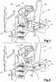
Fig. 1 shows the driver's cab of a commercial vehicle according to the invention in a schematic broken perspective view, with a driver unit in a first mode of position, and -
Fig. 2 shows the truck according toFig. 1 with the driver unit in a second mode of position. -
Fig. 1 and 2 show in a broken view a commercial truck comprising a driver'scab 10 and achassis 11. The driver's cab is provided with aside door 12, a driver'sseat 13 and aninstrument cluster 14 with asteering wheel 15. Thecab 10 is suspended in a conventional manner in relation to thechassis 11 via not shown suspension means. - The lower part of the cab is provided with a double floor comprising a
primary floor 16 and a secondary floor, together forming a cavity below the interior of the cab. This cavity can be used for housing equipment including electrical components, for example a vehicle control unit, and also a unit for controlling the cab interior temperature and ventilation, for example an air conditioning unit. - The provision of a double floor cavity makes it possible to equip the cab with a vertically suspended
driver unit 17 comprising afloor structure 17a including the driver'sseat 13, the instrument cluster withsteering wheel 15 and speed controls for the vehicle. The speed controls may comprise pedals for speed and braking and also a gear selector (not shown in the drawings). Thefloor structure 16 is mounted upon the secondary floor via fourshock absorber units 18. - The cab is provided with a locking mechanism for preventing the floor structure from moving vertically in relation to the cab when the vehicle is immobile. Mechanical springs may be used to preload the shock absorber units. A locking mechanism comprising lock bolts may be used for arresting the floor structure in a fixed position, so that the top of the floor structure is level with the top of the primary floor.
- Alternatively, the shock absorber units may use hydraulic dampers to dampen vertical movements of the floor structure. Valves in the hydraulic circuits of the dampers can then be used for locking the floor structure in any position within the range of vertical movement. Preferably, air pressure is used for providing adjustable preload of the shock absorber units. The adjustable preload may be utilized for automatic control of seat ride height, for example in relation to driver weight or in relation to driver length, by increasing or decreasing the air pressure preload. Control of seat ride height may be manual, alternatively via programmable memory settings or via a fully automatic sensor controlled system.
- The locking mechanism for the
floor structure 17a is preferably operated/controlled by means of a vehicle parking brake system to prevent the floor structure from moving vertically when the parking brake system is activated. When the locking system for the driver unit floor structure is activated, the cab floor including the driver unit floor structure provides a continuous flat surface, which is safe for moving around inside the cab when it is parked. Also, exiting thecab 10 via thedoor 12 is made safer by having a stable surface to step down from the area of theupper step 19 to themiddle step 20. - According to an advantageous embodiment of the invention, the
upper step 19 is connected to the suspendedfloor structure 17a, so that it is level with the top of theprimary floor 16. When the vehicle is parked, the driver unit is normally locked in a first mode of position so the top of the floor structure is level with theprimary floor 16 of the vehicle. When the driver is going to exit thecab 10, the driver can lower the driver unit to a second mode of position, in which theupper step 19 comes closer to the nextmiddle step 20 for entering or exiting the cab. The positioning of the driver unit can be controlled by different means, for example by means of remote control via a button on the vehicle door lock key. Alternatively, the positioning of the driver unit can be automatically controlled by a door lock sensor, so that the driver unit is moved from its first mode of position to its second mode of position when thecab door 12 is opened and vice versa. In this manner, entering or exiting the cab of a commercial truck is made easier and safer. Preferably, the automatic repositioning of thedriver unit 17 can be switched off if desired. - The invention has mainly been described above with reference to the disclosed embodiments. However, as is readily appreciated by the person skilled in the art, embodiments other than the ones disclosed above are equally possible within the scope of the invention, as defined by the appended claims.
Claims (9)
- A vehicle with a driver's cab (10) comprising a driver seat unit (17) with a vertically suspended floor structure (17a) including means for steering control (15), means for speed control and a driver's seat (13), characterized in that the cab is provided with a locking mechanism for preventing the floor structure (17a) from moving vertically in relation to the cab (10) when the vehicle is immobile and in that the floor structure (17a) is arranged in a cab with a primary floor (16) and a secondary floor positioned a certain distance below the primary floor (16).
- The vehicle as claimed in claim 1, characterized in that the floor structure is adapted to be restrained in a first mode of position level with the primary floor (16) of the vehicle.
- The vehicle according to claim 2, characterized in that the floor structure (17a) is able to release and reposition itself from said first mode of position to a second mode of position below said first mode of position, to form a step (19) for climbing into and out of the driver's cab.
- The vehicle according to claim 3, characterized in that the repositioning of the floor structure (17a) between said two modes of position is actuated by means of the opening and closing of the driver's door (12), so that the floor structure is lowered to the second mode of position when the driver's door is opened and raised to the first mode of position when the driver's door is closed.
- The vehicle according to claim 4, characterized in that actuation of repositioning of the floor structure (17a) via opening and closing of the driver's door (12) can be switched on or off.
- The vehicle according to any one of claims 1-5, characterized in that the floor structure is suspended by means of a pneumatically controlled spring system (18).
- The vehicle according to claim 6, characterized in that the pneumatically controlled spring system (18) is adapted to control seat ride height relative to driver weight.
- The vehicle according to claim 7, characterized in that the pneumatically controlled spring system (18) is also adapted to control seat ride height in relation to driver length.
- The vehicle according to any one of claims 1-8, characterized in that vertical motion of the floor structure (17a) is controlled by means of a hydraulic piston.
Priority Applications (1)
| Application Number | Priority Date | Filing Date | Title |
|---|---|---|---|
| EP16202806.2A EP3159246B1 (en) | 2012-05-08 | 2012-05-08 | A vehicle comprising a driver seat unit |
Applications Claiming Priority (3)
| Application Number | Priority Date | Filing Date | Title |
|---|---|---|---|
| PCT/SE2012/000067 WO2014003609A1 (en) | 2012-05-08 | 2012-05-08 | A vehicle with a driver seat unit comprising a vertically suspended floor structure |
| EP16202806.2A EP3159246B1 (en) | 2012-05-08 | 2012-05-08 | A vehicle comprising a driver seat unit |
| EP12879855.0A EP2847062B1 (en) | 2012-05-08 | 2012-05-08 | A vehicle with a driver seat unit comprising a vertically suspended floor structure |
Related Parent Applications (2)
| Application Number | Title | Priority Date | Filing Date |
|---|---|---|---|
| EP12879855.0A Division EP2847062B1 (en) | 2012-05-08 | 2012-05-08 | A vehicle with a driver seat unit comprising a vertically suspended floor structure |
| EP12879855.0A Division-Into EP2847062B1 (en) | 2012-05-08 | 2012-05-08 | A vehicle with a driver seat unit comprising a vertically suspended floor structure |
Publications (2)
| Publication Number | Publication Date |
|---|---|
| EP3159246A1 true EP3159246A1 (en) | 2017-04-26 |
| EP3159246B1 EP3159246B1 (en) | 2018-08-01 |
Family
ID=49783594
Family Applications (2)
| Application Number | Title | Priority Date | Filing Date |
|---|---|---|---|
| EP12879855.0A Active EP2847062B1 (en) | 2012-05-08 | 2012-05-08 | A vehicle with a driver seat unit comprising a vertically suspended floor structure |
| EP16202806.2A Active EP3159246B1 (en) | 2012-05-08 | 2012-05-08 | A vehicle comprising a driver seat unit |
Family Applications Before (1)
| Application Number | Title | Priority Date | Filing Date |
|---|---|---|---|
| EP12879855.0A Active EP2847062B1 (en) | 2012-05-08 | 2012-05-08 | A vehicle with a driver seat unit comprising a vertically suspended floor structure |
Country Status (4)
| Country | Link |
|---|---|
| US (1) | US9365141B2 (en) |
| EP (2) | EP2847062B1 (en) |
| JP (1) | JP6046240B2 (en) |
| WO (1) | WO2014003609A1 (en) |
Families Citing this family (6)
| Publication number | Priority date | Publication date | Assignee | Title |
|---|---|---|---|---|
| DE102016004530A1 (en) * | 2016-04-13 | 2017-10-19 | Man Truck & Bus Ag | Method and device for selecting and automatically adjusting an interior configuration of a cab of a commercial vehicle |
| IT201600093800A1 (en) * | 2016-09-19 | 2018-03-19 | Iveco Spa | DRIVING STATION FOR A COMMERCIAL OR HEAVY VEHICLE AND COMMERCIAL OR HEAVY VEHICLE INCLUDING THIS DRIVING STATION |
| DE102017009249B4 (en) | 2017-01-02 | 2020-09-17 | Bomag Gmbh | Small paver and procedures for operating a small paver |
| DE102018202074A1 (en) * | 2018-02-09 | 2019-08-14 | Wirtgen Gmbh | Soil cultivation machine with pluggable operating seat |
| GB2580070B (en) * | 2018-12-20 | 2021-01-06 | Smith Andrew | Improvements relating to motor vehicles |
| US11110831B2 (en) * | 2019-02-25 | 2021-09-07 | Scott Coffman | Force absorbing vehicle seat mounting system |
Citations (3)
| Publication number | Priority date | Publication date | Assignee | Title |
|---|---|---|---|---|
| DD110815A1 (en) * | 1974-04-08 | 1975-01-12 | ||
| GB1440686A (en) * | 1973-11-22 | 1976-06-23 | Uop Inc | Vehicle control assemblies |
| DE102010054410A1 (en) * | 2010-12-14 | 2011-07-28 | Daimler AG, 70327 | Truck has driving cab that is supported on vehicle frame, where structure is provided in area of driving cab in spring-mounted manner, and seating system is firmly connected with structure |
Family Cites Families (16)
| Publication number | Priority date | Publication date | Assignee | Title |
|---|---|---|---|---|
| GB1372700A (en) | 1970-12-31 | 1974-11-06 | Universal Oil Prod Co | Vehicle control assemblies |
| JPS5743712A (en) * | 1980-08-29 | 1982-03-11 | Tachikawa Spring Co | Air suspension |
| JP2580789B2 (en) | 1989-09-11 | 1997-02-12 | 凸版印刷株式会社 | IC card |
| JPH0810072Y2 (en) * | 1990-01-29 | 1996-03-27 | 日野自動車工業株式会社 | Cab suspension system for vehicles with cab |
| JPH06286649A (en) | 1993-03-30 | 1994-10-11 | Isuzu Motors Ltd | Attitude controller for cab |
| US5536059A (en) * | 1994-11-04 | 1996-07-16 | University Of Illinois | Seat suspension system using human body responses |
| SE513346C2 (en) * | 1999-02-12 | 2000-08-28 | Scania Cv Ab | Method of device when hanging a cab on a vehicle frame |
| JP3798572B2 (en) * | 1999-04-19 | 2006-07-19 | 日立建機株式会社 | Construction machinery cab |
| JP2003026051A (en) | 2001-07-12 | 2003-01-29 | Hino Motors Ltd | Car height adjusting device |
| JP2005075232A (en) | 2003-09-02 | 2005-03-24 | Nissan Diesel Motor Co Ltd | Suspension for vehicle |
| JP2006077544A (en) * | 2004-09-13 | 2006-03-23 | Hitachi Constr Mach Co Ltd | Cabin device of construction machine |
| US7887033B2 (en) * | 2006-06-06 | 2011-02-15 | Deere & Company | Suspension system having active compensation for vibration |
| JP5337021B2 (en) * | 2007-03-23 | 2013-11-06 | 株式会社小松製作所 | Vibration isolator |
| DE102007022654A1 (en) * | 2007-05-15 | 2008-02-07 | Daimler Ag | Driver activity area in driving cab of motor vehicle, has base module which is fastened in spring mounted manner in driving cab with three bearing points and seating module, or steering module, or pedal module is arranged on base module |
| JP5743712B2 (en) | 2011-05-20 | 2015-07-01 | 京セラ株式会社 | Electronic component storage package and electronic device |
| US8991538B2 (en) * | 2013-03-06 | 2015-03-31 | Paccar Inc | Cab suspension and repositioning system |
-
2012
- 2012-05-08 EP EP12879855.0A patent/EP2847062B1/en active Active
- 2012-05-08 EP EP16202806.2A patent/EP3159246B1/en active Active
- 2012-05-08 WO PCT/SE2012/000067 patent/WO2014003609A1/en active Application Filing
- 2012-05-08 US US14/399,540 patent/US9365141B2/en active Active
- 2012-05-08 JP JP2015511399A patent/JP6046240B2/en not_active Expired - Fee Related
Patent Citations (3)
| Publication number | Priority date | Publication date | Assignee | Title |
|---|---|---|---|---|
| GB1440686A (en) * | 1973-11-22 | 1976-06-23 | Uop Inc | Vehicle control assemblies |
| DD110815A1 (en) * | 1974-04-08 | 1975-01-12 | ||
| DE102010054410A1 (en) * | 2010-12-14 | 2011-07-28 | Daimler AG, 70327 | Truck has driving cab that is supported on vehicle frame, where structure is provided in area of driving cab in spring-mounted manner, and seating system is firmly connected with structure |
Also Published As
| Publication number | Publication date |
|---|---|
| EP3159246B1 (en) | 2018-08-01 |
| WO2014003609A1 (en) | 2014-01-03 |
| JP2015520693A (en) | 2015-07-23 |
| EP2847062A1 (en) | 2015-03-18 |
| EP2847062A4 (en) | 2015-12-30 |
| US20150217664A1 (en) | 2015-08-06 |
| EP2847062B1 (en) | 2017-03-29 |
| JP6046240B2 (en) | 2016-12-14 |
| US9365141B2 (en) | 2016-06-14 |
Similar Documents
| Publication | Publication Date | Title |
|---|---|---|
| EP3159246B1 (en) | A vehicle comprising a driver seat unit | |
| EP3498548B1 (en) | Lifting support assembly with a safety device | |
| US6120082A (en) | Integrated active seat suspension and seat lockup device | |
| EP2496441B1 (en) | Vehicle for deploying a mobile surveillance module | |
| CN108698465B (en) | Mechanically operated level adjusting valve device | |
| US10758433B2 (en) | Wheelchair vehicle entry system | |
| CA3012008A1 (en) | Integrated systems for passenger bus | |
| CN207190988U (en) | A kind of car anti-rollover system based on electronic control air suspension system | |
| EP2072323A1 (en) | Cushioned intermediate system for seat, in particular for vehicle seat | |
| CN103303241A (en) | Escape device for automobile falling into water as well as control system and control method of escape device | |
| EP2644417A3 (en) | Method for the level adjustment of a motor vehicle with pneumatic suspension | |
| US6629322B1 (en) | Manual assisted vertical lift bed | |
| US9457846B2 (en) | Vehicle with a suspended driver unit with locking and force absorbing means | |
| AU2015101572B4 (en) | Auto lift trailer | |
| WO2008073026A1 (en) | Bed arrangement for vehicles | |
| CN109751354A (en) | Air-supported shock absorber and the suspension system using the air-supported shock absorber, vehicle | |
| DE102017010138A1 (en) | A - R - O - SyS. The AROSYS system is designed to protect drivers and vehicles from falling over, causing them to crash and tip over, and implicitly people and cargo | |
| KR101613625B1 (en) | A wrecker using a underlift | |
| US11904649B1 (en) | Vehicle with independently adjustable suspension | |
| KR20190047152A (en) | Self Vehicle Direction Switching Apparatus | |
| CN216641600U (en) | Intelligent garage system based on PLC control | |
| KR20140048769A (en) | Mechanical 3 step height control apparatus for air-suspension of vehicle | |
| EP1247664A2 (en) | Tilt control apparatus for vehicles | |
| JP3884250B2 (en) | Vehicle height displacement suppression device | |
| CN203228614U (en) | Medical treatment cabin load self-adaption system of ambulance |
Legal Events
| Date | Code | Title | Description |
|---|---|---|---|
| PUAI | Public reference made under article 153(3) epc to a published international application that has entered the european phase |
Free format text: ORIGINAL CODE: 0009012 |
|
| STAA | Information on the status of an ep patent application or granted ep patent |
Free format text: STATUS: THE APPLICATION HAS BEEN PUBLISHED |
|
| AC | Divisional application: reference to earlier application |
Ref document number: 2847062 Country of ref document: EP Kind code of ref document: P |
|
| AK | Designated contracting states |
Kind code of ref document: A1 Designated state(s): AL AT BE BG CH CY CZ DE DK EE ES FI FR GB GR HR HU IE IS IT LI LT LU LV MC MK MT NL NO PL PT RO RS SE SI SK SM TR |
|
| STAA | Information on the status of an ep patent application or granted ep patent |
Free format text: STATUS: REQUEST FOR EXAMINATION WAS MADE |
|
| 17P | Request for examination filed |
Effective date: 20171024 |
|
| RBV | Designated contracting states (corrected) |
Designated state(s): AL AT BE BG CH CY CZ DE DK EE ES FI FR GB GR HR HU IE IS IT LI LT LU LV MC MK MT NL NO PL PT RO RS SE SI SK SM TR |
|
| GRAP | Despatch of communication of intention to grant a patent |
Free format text: ORIGINAL CODE: EPIDOSNIGR1 |
|
| STAA | Information on the status of an ep patent application or granted ep patent |
Free format text: STATUS: GRANT OF PATENT IS INTENDED |
|
| INTG | Intention to grant announced |
Effective date: 20180316 |
|
| GRAS | Grant fee paid |
Free format text: ORIGINAL CODE: EPIDOSNIGR3 |
|
| GRAA | (expected) grant |
Free format text: ORIGINAL CODE: 0009210 |
|
| STAA | Information on the status of an ep patent application or granted ep patent |
Free format text: STATUS: THE PATENT HAS BEEN GRANTED |
|
| AC | Divisional application: reference to earlier application |
Ref document number: 2847062 Country of ref document: EP Kind code of ref document: P |
|
| AK | Designated contracting states |
Kind code of ref document: B1 Designated state(s): AL AT BE BG CH CY CZ DE DK EE ES FI FR GB GR HR HU IE IS IT LI LT LU LV MC MK MT NL NO PL PT RO RS SE SI SK SM TR |
|
| REG | Reference to a national code |
Ref country code: GB Ref legal event code: FG4D |
|
| REG | Reference to a national code |
Ref country code: CH Ref legal event code: EP Ref country code: AT Ref legal event code: REF Ref document number: 1023941 Country of ref document: AT Kind code of ref document: T Effective date: 20180815 |
|
| REG | Reference to a national code |
Ref country code: IE Ref legal event code: FG4D |
|
| REG | Reference to a national code |
Ref country code: DE Ref legal event code: R096 Ref document number: 602012049328 Country of ref document: DE |
|
| REG | Reference to a national code |
Ref country code: NL Ref legal event code: MP Effective date: 20180801 |
|
| REG | Reference to a national code |
Ref country code: LT Ref legal event code: MG4D |
|
| REG | Reference to a national code |
Ref country code: AT Ref legal event code: MK05 Ref document number: 1023941 Country of ref document: AT Kind code of ref document: T Effective date: 20180801 |
|
| PG25 | Lapsed in a contracting state [announced via postgrant information from national office to epo] |
Ref country code: LT Free format text: LAPSE BECAUSE OF FAILURE TO SUBMIT A TRANSLATION OF THE DESCRIPTION OR TO PAY THE FEE WITHIN THE PRESCRIBED TIME-LIMIT Effective date: 20180801 Ref country code: RS Free format text: LAPSE BECAUSE OF FAILURE TO SUBMIT A TRANSLATION OF THE DESCRIPTION OR TO PAY THE FEE WITHIN THE PRESCRIBED TIME-LIMIT Effective date: 20180801 Ref country code: PL Free format text: LAPSE BECAUSE OF FAILURE TO SUBMIT A TRANSLATION OF THE DESCRIPTION OR TO PAY THE FEE WITHIN THE PRESCRIBED TIME-LIMIT Effective date: 20180801 Ref country code: AT Free format text: LAPSE BECAUSE OF FAILURE TO SUBMIT A TRANSLATION OF THE DESCRIPTION OR TO PAY THE FEE WITHIN THE PRESCRIBED TIME-LIMIT Effective date: 20180801 Ref country code: NO Free format text: LAPSE BECAUSE OF FAILURE TO SUBMIT A TRANSLATION OF THE DESCRIPTION OR TO PAY THE FEE WITHIN THE PRESCRIBED TIME-LIMIT Effective date: 20181101 Ref country code: IS Free format text: LAPSE BECAUSE OF FAILURE TO SUBMIT A TRANSLATION OF THE DESCRIPTION OR TO PAY THE FEE WITHIN THE PRESCRIBED TIME-LIMIT Effective date: 20181201 Ref country code: FI Free format text: LAPSE BECAUSE OF FAILURE TO SUBMIT A TRANSLATION OF THE DESCRIPTION OR TO PAY THE FEE WITHIN THE PRESCRIBED TIME-LIMIT Effective date: 20180801 Ref country code: GR Free format text: LAPSE BECAUSE OF FAILURE TO SUBMIT A TRANSLATION OF THE DESCRIPTION OR TO PAY THE FEE WITHIN THE PRESCRIBED TIME-LIMIT Effective date: 20181102 Ref country code: SE Free format text: LAPSE BECAUSE OF FAILURE TO SUBMIT A TRANSLATION OF THE DESCRIPTION OR TO PAY THE FEE WITHIN THE PRESCRIBED TIME-LIMIT Effective date: 20180801 Ref country code: BG Free format text: LAPSE BECAUSE OF FAILURE TO SUBMIT A TRANSLATION OF THE DESCRIPTION OR TO PAY THE FEE WITHIN THE PRESCRIBED TIME-LIMIT Effective date: 20181101 Ref country code: NL Free format text: LAPSE BECAUSE OF FAILURE TO SUBMIT A TRANSLATION OF THE DESCRIPTION OR TO PAY THE FEE WITHIN THE PRESCRIBED TIME-LIMIT Effective date: 20180801 |
|
| PG25 | Lapsed in a contracting state [announced via postgrant information from national office to epo] |
Ref country code: LV Free format text: LAPSE BECAUSE OF FAILURE TO SUBMIT A TRANSLATION OF THE DESCRIPTION OR TO PAY THE FEE WITHIN THE PRESCRIBED TIME-LIMIT Effective date: 20180801 Ref country code: AL Free format text: LAPSE BECAUSE OF FAILURE TO SUBMIT A TRANSLATION OF THE DESCRIPTION OR TO PAY THE FEE WITHIN THE PRESCRIBED TIME-LIMIT Effective date: 20180801 Ref country code: HR Free format text: LAPSE BECAUSE OF FAILURE TO SUBMIT A TRANSLATION OF THE DESCRIPTION OR TO PAY THE FEE WITHIN THE PRESCRIBED TIME-LIMIT Effective date: 20180801 |
|
| PG25 | Lapsed in a contracting state [announced via postgrant information from national office to epo] |
Ref country code: RO Free format text: LAPSE BECAUSE OF FAILURE TO SUBMIT A TRANSLATION OF THE DESCRIPTION OR TO PAY THE FEE WITHIN THE PRESCRIBED TIME-LIMIT Effective date: 20180801 Ref country code: IT Free format text: LAPSE BECAUSE OF FAILURE TO SUBMIT A TRANSLATION OF THE DESCRIPTION OR TO PAY THE FEE WITHIN THE PRESCRIBED TIME-LIMIT Effective date: 20180801 Ref country code: ES Free format text: LAPSE BECAUSE OF FAILURE TO SUBMIT A TRANSLATION OF THE DESCRIPTION OR TO PAY THE FEE WITHIN THE PRESCRIBED TIME-LIMIT Effective date: 20180801 Ref country code: CZ Free format text: LAPSE BECAUSE OF FAILURE TO SUBMIT A TRANSLATION OF THE DESCRIPTION OR TO PAY THE FEE WITHIN THE PRESCRIBED TIME-LIMIT Effective date: 20180801 Ref country code: EE Free format text: LAPSE BECAUSE OF FAILURE TO SUBMIT A TRANSLATION OF THE DESCRIPTION OR TO PAY THE FEE WITHIN THE PRESCRIBED TIME-LIMIT Effective date: 20180801 |
|
| REG | Reference to a national code |
Ref country code: DE Ref legal event code: R097 Ref document number: 602012049328 Country of ref document: DE |
|
| PG25 | Lapsed in a contracting state [announced via postgrant information from national office to epo] |
Ref country code: SK Free format text: LAPSE BECAUSE OF FAILURE TO SUBMIT A TRANSLATION OF THE DESCRIPTION OR TO PAY THE FEE WITHIN THE PRESCRIBED TIME-LIMIT Effective date: 20180801 Ref country code: DK Free format text: LAPSE BECAUSE OF FAILURE TO SUBMIT A TRANSLATION OF THE DESCRIPTION OR TO PAY THE FEE WITHIN THE PRESCRIBED TIME-LIMIT Effective date: 20180801 Ref country code: SM Free format text: LAPSE BECAUSE OF FAILURE TO SUBMIT A TRANSLATION OF THE DESCRIPTION OR TO PAY THE FEE WITHIN THE PRESCRIBED TIME-LIMIT Effective date: 20180801 |
|
| PLBE | No opposition filed within time limit |
Free format text: ORIGINAL CODE: 0009261 |
|
| STAA | Information on the status of an ep patent application or granted ep patent |
Free format text: STATUS: NO OPPOSITION FILED WITHIN TIME LIMIT |
|
| 26N | No opposition filed |
Effective date: 20190503 |
|
| PG25 | Lapsed in a contracting state [announced via postgrant information from national office to epo] |
Ref country code: SI Free format text: LAPSE BECAUSE OF FAILURE TO SUBMIT A TRANSLATION OF THE DESCRIPTION OR TO PAY THE FEE WITHIN THE PRESCRIBED TIME-LIMIT Effective date: 20180801 |
|
| REG | Reference to a national code |
Ref country code: CH Ref legal event code: PL |
|
| GBPC | Gb: european patent ceased through non-payment of renewal fee |
Effective date: 20190508 |
|
| PG25 | Lapsed in a contracting state [announced via postgrant information from national office to epo] |
Ref country code: LI Free format text: LAPSE BECAUSE OF NON-PAYMENT OF DUE FEES Effective date: 20190531 Ref country code: CH Free format text: LAPSE BECAUSE OF NON-PAYMENT OF DUE FEES Effective date: 20190531 Ref country code: MC Free format text: LAPSE BECAUSE OF FAILURE TO SUBMIT A TRANSLATION OF THE DESCRIPTION OR TO PAY THE FEE WITHIN THE PRESCRIBED TIME-LIMIT Effective date: 20180801 |
|
| REG | Reference to a national code |
Ref country code: BE Ref legal event code: MM Effective date: 20190531 |
|
| PG25 | Lapsed in a contracting state [announced via postgrant information from national office to epo] |
Ref country code: LU Free format text: LAPSE BECAUSE OF NON-PAYMENT OF DUE FEES Effective date: 20190508 |
|
| PG25 | Lapsed in a contracting state [announced via postgrant information from national office to epo] |
Ref country code: TR Free format text: LAPSE BECAUSE OF FAILURE TO SUBMIT A TRANSLATION OF THE DESCRIPTION OR TO PAY THE FEE WITHIN THE PRESCRIBED TIME-LIMIT Effective date: 20180801 |
|
| PG25 | Lapsed in a contracting state [announced via postgrant information from national office to epo] |
Ref country code: IE Free format text: LAPSE BECAUSE OF NON-PAYMENT OF DUE FEES Effective date: 20190508 Ref country code: GB Free format text: LAPSE BECAUSE OF NON-PAYMENT OF DUE FEES Effective date: 20190508 |
|
| PG25 | Lapsed in a contracting state [announced via postgrant information from national office to epo] |
Ref country code: BE Free format text: LAPSE BECAUSE OF NON-PAYMENT OF DUE FEES Effective date: 20190531 |
|
| PG25 | Lapsed in a contracting state [announced via postgrant information from national office to epo] |
Ref country code: PT Free format text: LAPSE BECAUSE OF FAILURE TO SUBMIT A TRANSLATION OF THE DESCRIPTION OR TO PAY THE FEE WITHIN THE PRESCRIBED TIME-LIMIT Effective date: 20181201 |
|
| PG25 | Lapsed in a contracting state [announced via postgrant information from national office to epo] |
Ref country code: CY Free format text: LAPSE BECAUSE OF FAILURE TO SUBMIT A TRANSLATION OF THE DESCRIPTION OR TO PAY THE FEE WITHIN THE PRESCRIBED TIME-LIMIT Effective date: 20180801 |
|
| PG25 | Lapsed in a contracting state [announced via postgrant information from national office to epo] |
Ref country code: MT Free format text: LAPSE BECAUSE OF FAILURE TO SUBMIT A TRANSLATION OF THE DESCRIPTION OR TO PAY THE FEE WITHIN THE PRESCRIBED TIME-LIMIT Effective date: 20180801 Ref country code: HU Free format text: LAPSE BECAUSE OF FAILURE TO SUBMIT A TRANSLATION OF THE DESCRIPTION OR TO PAY THE FEE WITHIN THE PRESCRIBED TIME-LIMIT; INVALID AB INITIO Effective date: 20120508 |
|
| PG25 | Lapsed in a contracting state [announced via postgrant information from national office to epo] |
Ref country code: MK Free format text: LAPSE BECAUSE OF FAILURE TO SUBMIT A TRANSLATION OF THE DESCRIPTION OR TO PAY THE FEE WITHIN THE PRESCRIBED TIME-LIMIT Effective date: 20180801 |
|
| PGFP | Annual fee paid to national office [announced via postgrant information from national office to epo] |
Ref country code: FR Payment date: 20230523 Year of fee payment: 12 Ref country code: DE Payment date: 20230530 Year of fee payment: 12 |