EP3162298A1 - Surgical stapler buttress assembly with adhesion to wet end effector - Google Patents
Surgical stapler buttress assembly with adhesion to wet end effector Download PDFInfo
- Publication number
- EP3162298A1 EP3162298A1 EP16196246.9A EP16196246A EP3162298A1 EP 3162298 A1 EP3162298 A1 EP 3162298A1 EP 16196246 A EP16196246 A EP 16196246A EP 3162298 A1 EP3162298 A1 EP 3162298A1
- Authority
- EP
- European Patent Office
- Prior art keywords
- buttress
- adhesive material
- tolerant adhesive
- anvil
- humidity
- Prior art date
- Legal status (The legal status is an assumption and is not a legal conclusion. Google has not performed a legal analysis and makes no representation as to the accuracy of the status listed.)
- Granted
Links
- 239000012636 effector Substances 0.000 title claims abstract description 120
- 239000000463 material Substances 0.000 claims abstract description 165
- 230000001070 adhesive effect Effects 0.000 claims abstract description 155
- 239000000853 adhesive Substances 0.000 claims abstract description 152
- 238000000034 method Methods 0.000 claims description 56
- 239000000203 mixture Substances 0.000 claims description 39
- 229920001983 poloxamer Polymers 0.000 claims description 31
- 229920001223 polyethylene glycol Polymers 0.000 claims description 30
- 239000002202 Polyethylene glycol Substances 0.000 claims description 29
- 229920001577 copolymer Polymers 0.000 claims description 26
- RVGRUAULSDPKGF-UHFFFAOYSA-N Poloxamer Chemical compound C1CO1.CC1CO1 RVGRUAULSDPKGF-UHFFFAOYSA-N 0.000 claims description 20
- -1 poly(caprolactone) Polymers 0.000 claims description 19
- 239000002594 sorbent Substances 0.000 claims description 12
- 239000000416 hydrocolloid Substances 0.000 claims description 10
- 150000003626 triacylglycerols Chemical class 0.000 claims description 8
- 229920002507 Poloxamer 124 Polymers 0.000 claims description 7
- 229940093448 poloxamer 124 Drugs 0.000 claims description 7
- 229920001993 poloxamer 188 Polymers 0.000 claims description 7
- 229940044519 poloxamer 188 Drugs 0.000 claims description 7
- 229920001992 poloxamer 407 Polymers 0.000 claims description 6
- 239000004698 Polyethylene Substances 0.000 claims description 5
- 229940044476 poloxamer 407 Drugs 0.000 claims description 5
- 239000007787 solid Substances 0.000 claims description 5
- 229920001400 block copolymer Polymers 0.000 claims description 4
- 230000036760 body temperature Effects 0.000 claims description 4
- 239000010410 layer Substances 0.000 description 37
- 229920000642 polymer Polymers 0.000 description 32
- 230000000712 assembly Effects 0.000 description 28
- 238000000429 assembly Methods 0.000 description 28
- 239000012790 adhesive layer Substances 0.000 description 13
- 238000010304 firing Methods 0.000 description 13
- 229920000954 Polyglycolide Polymers 0.000 description 11
- 229920001610 polycaprolactone Polymers 0.000 description 9
- 230000007246 mechanism Effects 0.000 description 8
- 229960000502 poloxamer Drugs 0.000 description 8
- 238000001356 surgical procedure Methods 0.000 description 8
- 238000005520 cutting process Methods 0.000 description 6
- 239000012530 fluid Substances 0.000 description 6
- 239000000499 gel Substances 0.000 description 6
- 230000009477 glass transition Effects 0.000 description 6
- 230000033001 locomotion Effects 0.000 description 6
- 230000004048 modification Effects 0.000 description 6
- 238000012986 modification Methods 0.000 description 6
- 238000009736 wetting Methods 0.000 description 6
- 239000003814 drug Substances 0.000 description 5
- 238000002844 melting Methods 0.000 description 5
- 230000008018 melting Effects 0.000 description 5
- 239000003921 oil Substances 0.000 description 5
- 230000004044 response Effects 0.000 description 5
- 229920002134 Carboxymethyl cellulose Polymers 0.000 description 4
- 108010010803 Gelatin Proteins 0.000 description 4
- 229920002472 Starch Polymers 0.000 description 4
- 229920002678 cellulose Polymers 0.000 description 4
- 239000001913 cellulose Substances 0.000 description 4
- 238000004090 dissolution Methods 0.000 description 4
- 239000006260 foam Substances 0.000 description 4
- 239000008273 gelatin Substances 0.000 description 4
- 229920000159 gelatin Polymers 0.000 description 4
- 235000019322 gelatine Nutrition 0.000 description 4
- 235000011852 gelatine desserts Nutrition 0.000 description 4
- 239000002874 hemostatic agent Substances 0.000 description 4
- 230000002209 hydrophobic effect Effects 0.000 description 4
- 229920003023 plastic Polymers 0.000 description 4
- 239000004033 plastic Substances 0.000 description 4
- 230000005855 radiation Effects 0.000 description 4
- 239000008107 starch Substances 0.000 description 4
- 235000019698 starch Nutrition 0.000 description 4
- 229920001661 Chitosan Polymers 0.000 description 3
- PEDCQBHIVMGVHV-UHFFFAOYSA-N Glycerine Chemical compound OCC(O)CO PEDCQBHIVMGVHV-UHFFFAOYSA-N 0.000 description 3
- 229940030225 antihemorrhagics Drugs 0.000 description 3
- 238000004140 cleaning Methods 0.000 description 3
- 229940079593 drug Drugs 0.000 description 3
- 238000001035 drying Methods 0.000 description 3
- 230000014509 gene expression Effects 0.000 description 3
- 238000009434 installation Methods 0.000 description 3
- 239000011159 matrix material Substances 0.000 description 3
- 210000000056 organ Anatomy 0.000 description 3
- 230000009467 reduction Effects 0.000 description 3
- 230000002787 reinforcement Effects 0.000 description 3
- 238000007789 sealing Methods 0.000 description 3
- 238000000926 separation method Methods 0.000 description 3
- 230000002269 spontaneous effect Effects 0.000 description 3
- 230000007704 transition Effects 0.000 description 3
- XLYOFNOQVPJJNP-UHFFFAOYSA-N water Substances O XLYOFNOQVPJJNP-UHFFFAOYSA-N 0.000 description 3
- 229920001817 Agar Polymers 0.000 description 2
- 102000009123 Fibrin Human genes 0.000 description 2
- 108010073385 Fibrin Proteins 0.000 description 2
- BWGVNKXGVNDBDI-UHFFFAOYSA-N Fibrin monomer Chemical compound CNC(=O)CNC(=O)CN BWGVNKXGVNDBDI-UHFFFAOYSA-N 0.000 description 2
- 239000004820 Pressure-sensitive adhesive Substances 0.000 description 2
- 239000002250 absorbent Substances 0.000 description 2
- 230000002745 absorbent Effects 0.000 description 2
- DPXJVFZANSGRMM-UHFFFAOYSA-N acetic acid;2,3,4,5,6-pentahydroxyhexanal;sodium Chemical compound [Na].CC(O)=O.OCC(O)C(O)C(O)C(O)C=O DPXJVFZANSGRMM-UHFFFAOYSA-N 0.000 description 2
- 239000008272 agar Substances 0.000 description 2
- 229920000615 alginic acid Polymers 0.000 description 2
- 235000010443 alginic acid Nutrition 0.000 description 2
- 230000005540 biological transmission Effects 0.000 description 2
- 230000000740 bleeding effect Effects 0.000 description 2
- 239000008280 blood Substances 0.000 description 2
- 210000004369 blood Anatomy 0.000 description 2
- 239000001768 carboxy methyl cellulose Substances 0.000 description 2
- 230000008859 change Effects 0.000 description 2
- 239000011248 coating agent Substances 0.000 description 2
- 238000000576 coating method Methods 0.000 description 2
- 239000003925 fat Substances 0.000 description 2
- 239000000835 fiber Substances 0.000 description 2
- 229950003499 fibrin Drugs 0.000 description 2
- 150000004676 glycans Chemical class 0.000 description 2
- 238000003780 insertion Methods 0.000 description 2
- 230000037431 insertion Effects 0.000 description 2
- 239000007788 liquid Substances 0.000 description 2
- HQKMJHAJHXVSDF-UHFFFAOYSA-L magnesium stearate Chemical compound [Mg+2].CCCCCCCCCCCCCCCCCC([O-])=O.CCCCCCCCCCCCCCCCCC([O-])=O HQKMJHAJHXVSDF-UHFFFAOYSA-L 0.000 description 2
- 230000014759 maintenance of location Effects 0.000 description 2
- 229920001206 natural gum Polymers 0.000 description 2
- 239000002736 nonionic surfactant Substances 0.000 description 2
- 238000000059 patterning Methods 0.000 description 2
- 239000001814 pectin Substances 0.000 description 2
- 235000010987 pectin Nutrition 0.000 description 2
- 229920001277 pectin Polymers 0.000 description 2
- 229920001282 polysaccharide Polymers 0.000 description 2
- 239000005017 polysaccharide Substances 0.000 description 2
- 229920001343 polytetrafluoroethylene Polymers 0.000 description 2
- 239000004810 polytetrafluoroethylene Substances 0.000 description 2
- 229920006316 polyvinylpyrrolidine Polymers 0.000 description 2
- 230000037452 priming Effects 0.000 description 2
- 235000019812 sodium carboxymethyl cellulose Nutrition 0.000 description 2
- 229920001027 sodium carboxymethylcellulose Polymers 0.000 description 2
- 125000006850 spacer group Chemical group 0.000 description 2
- 210000000115 thoracic cavity Anatomy 0.000 description 2
- 238000011282 treatment Methods 0.000 description 2
- URAYPUMNDPQOKB-UHFFFAOYSA-N triacetin Chemical compound CC(=O)OCC(OC(C)=O)COC(C)=O URAYPUMNDPQOKB-UHFFFAOYSA-N 0.000 description 2
- WCDDVEOXEIYWFB-VXORFPGASA-N (2s,3s,4r,5r,6r)-3-[(2s,3r,5s,6r)-3-acetamido-5-hydroxy-6-(hydroxymethyl)oxan-2-yl]oxy-4,5,6-trihydroxyoxane-2-carboxylic acid Chemical compound CC(=O)N[C@@H]1C[C@H](O)[C@@H](CO)O[C@H]1O[C@@H]1[C@@H](C(O)=O)O[C@@H](O)[C@H](O)[C@H]1O WCDDVEOXEIYWFB-VXORFPGASA-N 0.000 description 1
- RKDVKSZUMVYZHH-UHFFFAOYSA-N 1,4-dioxane-2,5-dione Chemical compound O=C1COC(=O)CO1 RKDVKSZUMVYZHH-UHFFFAOYSA-N 0.000 description 1
- FDCJDKXCCYFOCV-UHFFFAOYSA-N 1-hexadecoxyhexadecane Chemical compound CCCCCCCCCCCCCCCCOCCCCCCCCCCCCCCCC FDCJDKXCCYFOCV-UHFFFAOYSA-N 0.000 description 1
- NMSBTWLFBGNKON-UHFFFAOYSA-N 2-(2-hexadecoxyethoxy)ethanol Chemical compound CCCCCCCCCCCCCCCCOCCOCCO NMSBTWLFBGNKON-UHFFFAOYSA-N 0.000 description 1
- 241000894006 Bacteria Species 0.000 description 1
- OMPIYDSYGYKWSG-UHFFFAOYSA-N Citronensaeure-alpha-aethylester Natural products CCOC(=O)CC(O)(C(O)=O)CC(O)=O OMPIYDSYGYKWSG-UHFFFAOYSA-N 0.000 description 1
- 102000008186 Collagen Human genes 0.000 description 1
- 108010035532 Collagen Proteins 0.000 description 1
- 239000001856 Ethyl cellulose Substances 0.000 description 1
- ZZSNKZQZMQGXPY-UHFFFAOYSA-N Ethyl cellulose Chemical compound CCOCC1OC(OC)C(OCC)C(OCC)C1OC1C(O)C(O)C(OC)C(CO)O1 ZZSNKZQZMQGXPY-UHFFFAOYSA-N 0.000 description 1
- IAYPIBMASNFSPL-UHFFFAOYSA-N Ethylene oxide Chemical compound C1CO1 IAYPIBMASNFSPL-UHFFFAOYSA-N 0.000 description 1
- 229920000604 Polyethylene Glycol 200 Polymers 0.000 description 1
- 229920002562 Polyethylene Glycol 3350 Polymers 0.000 description 1
- 229920002565 Polyethylene Glycol 400 Polymers 0.000 description 1
- 108090000190 Thrombin Proteins 0.000 description 1
- DOOTYTYQINUNNV-UHFFFAOYSA-N Triethyl citrate Chemical compound CCOC(=O)CC(O)(C(=O)OCC)CC(=O)OCC DOOTYTYQINUNNV-UHFFFAOYSA-N 0.000 description 1
- BAECOWNUKCLBPZ-HIUWNOOHSA-N Triolein Natural products O([C@H](OCC(=O)CCCCCCC/C=C\CCCCCCCC)COC(=O)CCCCCCC/C=C\CCCCCCCC)C(=O)CCCCCCC/C=C\CCCCCCCC BAECOWNUKCLBPZ-HIUWNOOHSA-N 0.000 description 1
- PHYFQTYBJUILEZ-UHFFFAOYSA-N Trioleoylglycerol Natural products CCCCCCCCC=CCCCCCCCC(=O)OCC(OC(=O)CCCCCCCC=CCCCCCCCC)COC(=O)CCCCCCCC=CCCCCCCCC PHYFQTYBJUILEZ-UHFFFAOYSA-N 0.000 description 1
- 210000001015 abdomen Anatomy 0.000 description 1
- 230000009471 action Effects 0.000 description 1
- 230000004913 activation Effects 0.000 description 1
- 230000006978 adaptation Effects 0.000 description 1
- 229920006125 amorphous polymer Polymers 0.000 description 1
- 230000003872 anastomosis Effects 0.000 description 1
- 238000003491 array Methods 0.000 description 1
- 239000011324 bead Substances 0.000 description 1
- 230000008901 benefit Effects 0.000 description 1
- 229920002988 biodegradable polymer Polymers 0.000 description 1
- 239000004621 biodegradable polymer Substances 0.000 description 1
- 230000015572 biosynthetic process Effects 0.000 description 1
- 210000001124 body fluid Anatomy 0.000 description 1
- CJZGTCYPCWQAJB-UHFFFAOYSA-L calcium stearate Chemical compound [Ca+2].CCCCCCCCCCCCCCCCCC([O-])=O.CCCCCCCCCCCCCCCCCC([O-])=O CJZGTCYPCWQAJB-UHFFFAOYSA-L 0.000 description 1
- 235000013539 calcium stearate Nutrition 0.000 description 1
- 239000008116 calcium stearate Substances 0.000 description 1
- 230000015556 catabolic process Effects 0.000 description 1
- 239000003153 chemical reaction reagent Substances 0.000 description 1
- 230000001112 coagulating effect Effects 0.000 description 1
- 229920001436 collagen Polymers 0.000 description 1
- 238000013270 controlled release Methods 0.000 description 1
- 230000008878 coupling Effects 0.000 description 1
- 238000010168 coupling process Methods 0.000 description 1
- 238000005859 coupling reaction Methods 0.000 description 1
- 238000004132 cross linking Methods 0.000 description 1
- MTHSVFCYNBDYFN-UHFFFAOYSA-N diethylene glycol Chemical compound OCCOCCO MTHSVFCYNBDYFN-UHFFFAOYSA-N 0.000 description 1
- 238000009826 distribution Methods 0.000 description 1
- 238000002651 drug therapy Methods 0.000 description 1
- 230000000694 effects Effects 0.000 description 1
- 235000019325 ethyl cellulose Nutrition 0.000 description 1
- 229920001249 ethyl cellulose Polymers 0.000 description 1
- 229940057975 ethyl citrate Drugs 0.000 description 1
- 230000002349 favourable effect Effects 0.000 description 1
- 239000002657 fibrous material Substances 0.000 description 1
- 238000011049 filling Methods 0.000 description 1
- 230000009969 flowable effect Effects 0.000 description 1
- 238000001415 gene therapy Methods 0.000 description 1
- 239000001087 glyceryl triacetate Substances 0.000 description 1
- 235000013773 glyceryl triacetate Nutrition 0.000 description 1
- 230000002439 hemostatic effect Effects 0.000 description 1
- 229940014041 hyaluronate Drugs 0.000 description 1
- 239000001866 hydroxypropyl methyl cellulose Substances 0.000 description 1
- 235000010979 hydroxypropyl methyl cellulose Nutrition 0.000 description 1
- 229920003088 hydroxypropyl methyl cellulose Polymers 0.000 description 1
- UFVKGYZPFZQRLF-UHFFFAOYSA-N hydroxypropyl methyl cellulose Chemical compound OC1C(O)C(OC)OC(CO)C1OC1C(O)C(O)C(OC2C(C(O)C(OC3C(C(O)C(O)C(CO)O3)O)C(CO)O2)O)C(CO)O1 UFVKGYZPFZQRLF-UHFFFAOYSA-N 0.000 description 1
- 238000002955 isolation Methods 0.000 description 1
- JJTUDXZGHPGLLC-UHFFFAOYSA-N lactide Chemical compound CC1OC(=O)C(C)OC1=O JJTUDXZGHPGLLC-UHFFFAOYSA-N 0.000 description 1
- 210000004072 lung Anatomy 0.000 description 1
- 235000019359 magnesium stearate Nutrition 0.000 description 1
- 238000002324 minimally invasive surgery Methods 0.000 description 1
- 238000002156 mixing Methods 0.000 description 1
- 230000001151 other effect Effects 0.000 description 1
- 229920000058 polyacrylate Polymers 0.000 description 1
- 229940113115 polyethylene glycol 200 Drugs 0.000 description 1
- 229940050929 polyethylene glycol 3350 Drugs 0.000 description 1
- 229940068918 polyethylene glycol 400 Drugs 0.000 description 1
- 239000004633 polyglycolic acid Substances 0.000 description 1
- 229920001451 polypropylene glycol Polymers 0.000 description 1
- 229920001296 polysiloxane Polymers 0.000 description 1
- 229920000136 polysorbate Polymers 0.000 description 1
- 229940068965 polysorbates Drugs 0.000 description 1
- 230000002980 postoperative effect Effects 0.000 description 1
- 230000002265 prevention Effects 0.000 description 1
- 230000001681 protective effect Effects 0.000 description 1
- 238000011084 recovery Methods 0.000 description 1
- 230000003014 reinforcing effect Effects 0.000 description 1
- 238000000518 rheometry Methods 0.000 description 1
- 239000000565 sealant Substances 0.000 description 1
- 230000035945 sensitivity Effects 0.000 description 1
- 238000010008 shearing Methods 0.000 description 1
- 230000007480 spreading Effects 0.000 description 1
- 238000003892 spreading Methods 0.000 description 1
- 230000001954 sterilising effect Effects 0.000 description 1
- 238000004659 sterilization and disinfection Methods 0.000 description 1
- 239000000126 substance Substances 0.000 description 1
- 229940124597 therapeutic agent Drugs 0.000 description 1
- 230000001225 therapeutic effect Effects 0.000 description 1
- 238000002560 therapeutic procedure Methods 0.000 description 1
- 229960004072 thrombin Drugs 0.000 description 1
- 238000012876 topography Methods 0.000 description 1
- 229960002622 triacetin Drugs 0.000 description 1
- 235000013769 triethyl citrate Nutrition 0.000 description 1
- YFHICDDUDORKJB-UHFFFAOYSA-N trimethylene carbonate Chemical compound O=C1OCCCO1 YFHICDDUDORKJB-UHFFFAOYSA-N 0.000 description 1
- PHYFQTYBJUILEZ-IUPFWZBJSA-N triolein Chemical compound CCCCCCCC\C=C/CCCCCCCC(=O)OCC(OC(=O)CCCCCCC\C=C/CCCCCCCC)COC(=O)CCCCCCC\C=C/CCCCCCCC PHYFQTYBJUILEZ-IUPFWZBJSA-N 0.000 description 1
- 229940117972 triolein Drugs 0.000 description 1
- 238000002604 ultrasonography Methods 0.000 description 1
- 210000001835 viscera Anatomy 0.000 description 1
- 210000000707 wrist Anatomy 0.000 description 1
Images


Classifications
-
- A—HUMAN NECESSITIES
- A61—MEDICAL OR VETERINARY SCIENCE; HYGIENE
- A61B—DIAGNOSIS; SURGERY; IDENTIFICATION
- A61B17/00—Surgical instruments, devices or methods, e.g. tourniquets
- A61B17/068—Surgical staplers, e.g. containing multiple staples or clamps
- A61B17/072—Surgical staplers, e.g. containing multiple staples or clamps for applying a row of staples in a single action, e.g. the staples being applied simultaneously
- A61B17/07207—Surgical staplers, e.g. containing multiple staples or clamps for applying a row of staples in a single action, e.g. the staples being applied simultaneously the staples being applied sequentially
-
- A—HUMAN NECESSITIES
- A61—MEDICAL OR VETERINARY SCIENCE; HYGIENE
- A61B—DIAGNOSIS; SURGERY; IDENTIFICATION
- A61B17/00—Surgical instruments, devices or methods, e.g. tourniquets
- A61B17/068—Surgical staplers, e.g. containing multiple staples or clamps
- A61B17/072—Surgical staplers, e.g. containing multiple staples or clamps for applying a row of staples in a single action, e.g. the staples being applied simultaneously
- A61B17/07292—Reinforcements for staple line, e.g. pledgets
-
- B—PERFORMING OPERATIONS; TRANSPORTING
- B29—WORKING OF PLASTICS; WORKING OF SUBSTANCES IN A PLASTIC STATE IN GENERAL
- B29C—SHAPING OR JOINING OF PLASTICS; SHAPING OF MATERIAL IN A PLASTIC STATE, NOT OTHERWISE PROVIDED FOR; AFTER-TREATMENT OF THE SHAPED PRODUCTS, e.g. REPAIRING
- B29C65/00—Joining or sealing of preformed parts, e.g. welding of plastics materials; Apparatus therefor
- B29C65/48—Joining or sealing of preformed parts, e.g. welding of plastics materials; Apparatus therefor using adhesives, i.e. using supplementary joining material; solvent bonding
-
- A—HUMAN NECESSITIES
- A61—MEDICAL OR VETERINARY SCIENCE; HYGIENE
- A61B—DIAGNOSIS; SURGERY; IDENTIFICATION
- A61B17/00—Surgical instruments, devices or methods, e.g. tourniquets
- A61B2017/00004—(bio)absorbable, (bio)resorbable, resorptive
-
- A—HUMAN NECESSITIES
- A61—MEDICAL OR VETERINARY SCIENCE; HYGIENE
- A61B—DIAGNOSIS; SURGERY; IDENTIFICATION
- A61B17/00—Surgical instruments, devices or methods, e.g. tourniquets
- A61B2017/00831—Material properties
- A61B2017/00938—Material properties hydrophobic
-
- A—HUMAN NECESSITIES
- A61—MEDICAL OR VETERINARY SCIENCE; HYGIENE
- A61B—DIAGNOSIS; SURGERY; IDENTIFICATION
- A61B17/00—Surgical instruments, devices or methods, e.g. tourniquets
- A61B2017/00831—Material properties
- A61B2017/00951—Material properties adhesive
-
- A—HUMAN NECESSITIES
- A61—MEDICAL OR VETERINARY SCIENCE; HYGIENE
- A61B—DIAGNOSIS; SURGERY; IDENTIFICATION
- A61B17/00—Surgical instruments, devices or methods, e.g. tourniquets
- A61B17/068—Surgical staplers, e.g. containing multiple staples or clamps
- A61B17/072—Surgical staplers, e.g. containing multiple staples or clamps for applying a row of staples in a single action, e.g. the staples being applied simultaneously
- A61B2017/07214—Stapler heads
- A61B2017/07257—Stapler heads characterised by its anvil
-
- A—HUMAN NECESSITIES
- A61—MEDICAL OR VETERINARY SCIENCE; HYGIENE
- A61B—DIAGNOSIS; SURGERY; IDENTIFICATION
- A61B17/00—Surgical instruments, devices or methods, e.g. tourniquets
- A61B17/068—Surgical staplers, e.g. containing multiple staples or clamps
- A61B17/072—Surgical staplers, e.g. containing multiple staples or clamps for applying a row of staples in a single action, e.g. the staples being applied simultaneously
- A61B2017/07214—Stapler heads
- A61B2017/07285—Stapler heads characterised by its cutter
-
- B—PERFORMING OPERATIONS; TRANSPORTING
- B29—WORKING OF PLASTICS; WORKING OF SUBSTANCES IN A PLASTIC STATE IN GENERAL
- B29C—SHAPING OR JOINING OF PLASTICS; SHAPING OF MATERIAL IN A PLASTIC STATE, NOT OTHERWISE PROVIDED FOR; AFTER-TREATMENT OF THE SHAPED PRODUCTS, e.g. REPAIRING
- B29C65/00—Joining or sealing of preformed parts, e.g. welding of plastics materials; Apparatus therefor
- B29C65/48—Joining or sealing of preformed parts, e.g. welding of plastics materials; Apparatus therefor using adhesives, i.e. using supplementary joining material; solvent bonding
- B29C65/4805—Joining or sealing of preformed parts, e.g. welding of plastics materials; Apparatus therefor using adhesives, i.e. using supplementary joining material; solvent bonding characterised by the type of adhesives
- B29C65/481—Non-reactive adhesives, e.g. physically hardening adhesives
- B29C65/4825—Pressure sensitive adhesives
-
- B—PERFORMING OPERATIONS; TRANSPORTING
- B29—WORKING OF PLASTICS; WORKING OF SUBSTANCES IN A PLASTIC STATE IN GENERAL
- B29C—SHAPING OR JOINING OF PLASTICS; SHAPING OF MATERIAL IN A PLASTIC STATE, NOT OTHERWISE PROVIDED FOR; AFTER-TREATMENT OF THE SHAPED PRODUCTS, e.g. REPAIRING
- B29C65/00—Joining or sealing of preformed parts, e.g. welding of plastics materials; Apparatus therefor
- B29C65/48—Joining or sealing of preformed parts, e.g. welding of plastics materials; Apparatus therefor using adhesives, i.e. using supplementary joining material; solvent bonding
- B29C65/52—Joining or sealing of preformed parts, e.g. welding of plastics materials; Apparatus therefor using adhesives, i.e. using supplementary joining material; solvent bonding characterised by the way of applying the adhesive
-
- B—PERFORMING OPERATIONS; TRANSPORTING
- B29—WORKING OF PLASTICS; WORKING OF SUBSTANCES IN A PLASTIC STATE IN GENERAL
- B29C—SHAPING OR JOINING OF PLASTICS; SHAPING OF MATERIAL IN A PLASTIC STATE, NOT OTHERWISE PROVIDED FOR; AFTER-TREATMENT OF THE SHAPED PRODUCTS, e.g. REPAIRING
- B29C66/00—General aspects of processes or apparatus for joining preformed parts
- B29C66/80—General aspects of machine operations or constructions and parts thereof
- B29C66/83—General aspects of machine operations or constructions and parts thereof characterised by the movement of the joining or pressing tools
- B29C66/832—Reciprocating joining or pressing tools
- B29C66/8324—Joining or pressing tools pivoting around one axis
-
- B—PERFORMING OPERATIONS; TRANSPORTING
- B29—WORKING OF PLASTICS; WORKING OF SUBSTANCES IN A PLASTIC STATE IN GENERAL
- B29C—SHAPING OR JOINING OF PLASTICS; SHAPING OF MATERIAL IN A PLASTIC STATE, NOT OTHERWISE PROVIDED FOR; AFTER-TREATMENT OF THE SHAPED PRODUCTS, e.g. REPAIRING
- B29C66/00—General aspects of processes or apparatus for joining preformed parts
- B29C66/80—General aspects of machine operations or constructions and parts thereof
- B29C66/84—Specific machine types or machines suitable for specific applications
- B29C66/861—Hand-held tools
- B29C66/8614—Tongs, pincers or scissors
-
- B—PERFORMING OPERATIONS; TRANSPORTING
- B29—WORKING OF PLASTICS; WORKING OF SUBSTANCES IN A PLASTIC STATE IN GENERAL
- B29L—INDEXING SCHEME ASSOCIATED WITH SUBCLASS B29C, RELATING TO PARTICULAR ARTICLES
- B29L2031/00—Other particular articles
- B29L2031/753—Medical equipment; Accessories therefor
- B29L2031/7546—Surgical equipment
Definitions
- endoscopic surgical instruments may be preferred over traditional open surgical devices since a smaller incision may reduce the post-operative recovery time and complications. Consequently, some endoscopic surgical instruments may be suitable for placement of a distal end effector at a desired surgical site through the cannula of a trocar. These distal end effectors may engage tissue in a number of ways to achieve a diagnostic or therapeutic effect (e.g., endocutter, grasper, cutter, stapler, clip applier, access device, drug/gene therapy delivery device, and energy delivery device using ultrasonic vibration, RF, laser, etc.). Endoscopic surgical instruments may include a shaft between the end effector and a handle portion, which is manipulated by the clinician.
- Such a shaft may enable insertion to a desired depth and rotation about the longitudinal axis of the shaft, thereby facilitating positioning of the end effector within the patient. Positioning of an end effector may be further facilitated through inclusion of one or more articulation joints or features, enabling the end effector to be selectively articulated or otherwise deflected relative to the longitudinal axis of the shaft.
- endoscopic surgical instruments include surgical staplers. Some such staplers are operable to clamp down on layers of tissue, cut through the clamped layers of tissue, and drive staples through the layers of tissue to substantially seal the severed layers of tissue together near the severed ends of the tissue layers.
- surgical staplers are disclosed in U.S. Pat. No. 4,805,823 , entitled “Pocket Configuration for Internal Organ Staplers,” issued February 21, 1989; U.S. Pat. No. 5,415,334 , entitled “Surgical Stapler and Staple Cartridge,” issued May 16, 1995; U.S. Pat. No. 5,465,895 , entitled “Surgical Stapler Instrument,” issued November 14, 1995; U.S. Pat. No.
- surgical staplers referred to above are described as being used in endoscopic procedures, it should be understood that such surgical staplers may also be used in open procedures and/or other non-endoscopic procedures.
- a surgical stapler may be inserted through a thoracotomy, and thereby between a patient's ribs, to reach one or more organs in a thoracic surgical procedure that does not use a trocar as a conduit for the stapler.
- Such procedures may include the use of the stapler to sever and close a vessel leading to a lung. For instance, the vessels leading to an organ may be severed and closed by a stapler before removal of the organ from the thoracic cavity.
- surgical staplers may be used in various other settings and procedures.
- 2014/0239036 entitled “Jaw Closure Feature for End Effector of Surgical Instrument,” published August 28, 2014; U.S. Patent Pub. No. 2014/0239040 , entitled “Surgical Instrument with Articulation Lock having a Detenting Binary Spring,” published August 28, 2014; U.S. Patent Pub. No. 2014/0239043 , entitled “Distal Tip Features for End Effector of Surgical Instrument,” published August 28, 2014; U.S. Patent Pub. No. 2014/0239037 , entitled “Staple Forming Features for Surgical Stapling Instrument,” published August 28, 2014; U.S. Patent Pub. No. 2014/0239038 , entitled “Surgical Instrument with Multi-Diameter Shaft,” published August 28, 2014; and U.S. Patent Pub. No. 2014/0239044 , entitled “Installation Features for Surgical Instrument End Effector Cartridge,” published August 28, 2014.
- a surgical stapling instrument may be desirable to equip a surgical stapling instrument with a buttress material to reinforce the mechanical fastening of tissue provided by staples.
- a buttress may prevent the applied staples from pulling through tissue and may otherwise reduce a risk of tissue tearing at or near the site of applied staples.
- FIG. 1 depicts an exemplary surgical stapling and severing instrument (10) that includes a handle assembly (20), a shaft assembly (30), and an end effector (40).
- End effector (40) and the distal portion of shaft assembly (30) are sized for insertion, in a nonarticulated state as depicted in FIG. 1 , through a trocar cannula to a surgical site in a patient for performing a surgical procedure.
- a trocar may be inserted in a patient's abdomen, between two of the patient's ribs, or elsewhere.
- instrument (10) is used without a trocar.
- end effector (40) and the distal portion of shaft assembly (30) may be inserted directly through a thoracotomy or other type of incision.
- terms such as “proximal” and “distal” are used herein with reference to a clinician gripping handle assembly (20) of instrument (10).
- end effector (40) is distal with respect to the more proximal handle assembly (20).
- spatial terms such as “vertical” and “horizontal” are used herein with respect to the drawings.
- surgical instruments are used in many orientations and positions, and these terms are not intended to be limiting and absolute.
- handle assembly (20) of the present example comprises pistol grip (22), a closure trigger (24), and a firing trigger (26). Each trigger (24, 26) is selectively pivotable toward and away from pistol grip (22) as will be described in greater detail below.
- Handle assembly (20) further includes a removable battery pack (28). These components will also be described in greater detail below.
- handle assembly (20) may have a variety of other components, features, and operabilities, in addition to or in lieu of any of those noted above.
- Other suitable configurations for handle assembly (20) will be apparent to those of ordinary skill in the art in view of the teachings herein.
- shaft assembly (30) of the present example comprises an outer closure tube (32), an articulation section (34), and a closure ring (36), which is further coupled with end effector (40).
- Closure tube (32) extends along the length of shaft assembly (30).
- Closure ring (36) is positioned distal to articulation section (34).
- Closure tube (32) and closure ring (36) are configured to translate longitudinally relative to handle assembly (20). Longitudinal translation of closure tube (32) is communicated to closure ring (36) via articulation section (34). Exemplary features that may be used to provide longitudinal translation of closure tube (32) and closure ring (36) will be described in greater detail below.
- Articulation section (34) is operable to laterally deflect closure ring (36) and end effector (40) laterally away from the longitudinal axis (LA) of shaft assembly (30) at a desired angle ( ⁇ ).
- articulation is controlled through an articulation control knob (35) which is located at the proximal end of shaft assembly (30).
- Closure ring (36) and end effector (40) pivot about an axis that is perpendicular to the longitudinal axis (LA) of shaft assembly (30) in response to rotation of knob (35).
- Articulation section (34) is configured to communicate longitudinal translation of closure tube (32) to closure ring (36), regardless of whether articulation section (34) is in a straight configuration or an articulated configuration.
- articulation section (34) and/or articulation control knob (35) may be constructed and operable in accordance with at least some of the teachings of U.S. Pub. No. 2014/0243801 , entitled “Surgical Instrument End Effector Articulation Drive with Pinion and Opposing Racks,” published August 28, 2014; and/or U.S. Pat. App. No. 14/314,125 , entitled “Articulation Drive Features for Surgical Stapler,” filed June 25, 2014; and/or in accordance with the various teachings below.
- Other suitable forms that articulation section (34) and articulation knob (35) may take will be apparent to those of ordinary skill in the art in view of the teachings herein.
- shaft assembly (30) of the present example further includes a rotation knob (31).
- Rotation knob (31) is operable to rotate the entire shaft assembly (30) and end effector (40) relative to handle assembly (20) about the longitudinal axis (LA) of shaft assembly (30).
- shaft assembly (30) may have a variety of other components, features, and operabilities, in addition to or in lieu of any of those noted above.
- at least part of shaft assembly (30) is constructed in accordance with at least some of the teachings of U.S. Pub. No. 2014/0239038 , entitled "Surgical Instrument with Multi-Diameter Shaft,” published August 28, 2014.
- Other suitable configurations for shaft assembly (30) will be apparent to those of ordinary skill in the art in view of the teachings herein.
- end effector (40) of the present example includes a lower jaw (50) and a pivotable anvil (60).
- Anvil (60) includes a pair of integral, outwardly extending pins (66) that are disposed in corresponding curved slots (54) of lower jaw (50).
- Anvil (60) is pivotable toward and away from lower jaw (50) between an open position (shown in FIG. 2 ) and a closed position (shown in FIG. 1 ).
- Use of the term "pivotable” (and similar terms with "pivot" as a base) should not be read as necessarily requiring pivotal movement about a fixed axis.
- anvil (60) pivots about an axis that is defined by pins (66), which slide along curved slots (54) of lower jaw (50) as anvil (60) moves toward lower jaw (50).
- the pivot axis translates along the path defined by slots (54) while anvil (60) simultaneously pivots about that axis.
- the pivot axis may slide along slots (54) first, with anvil (60) then pivoting about the pivot axis after the pivot axis has slid a certain distance along the slots (54).
- pivotal movement is encompassed within terms such as “pivot,” “pivots,” “pivotal,” “pivotable,” “pivoting,” and the like.
- some versions may provide pivotal movement of anvil (60) about an axis that remains fixed and does not translate within a slot or channel, etc.
- lower jaw (50) of the present example defines a channel (52) that is configured to receive a staple cartridge (70).
- Staple cartridge (70) may be inserted into channel (52), end effector (40) may be actuated, and then staple cartridge (70) may be removed and replaced with another staple cartridge (70).
- Lower jaw (50) thus releasably retains staple cartridge (70) in alignment with anvil (60) for actuation of end effector (40).
- lower jaw (50) is constructed in accordance with at least some of the teachings of U.S. Pub. No. 2014/0239044 , entitled "Installation Features for Surgical Instrument End Effector Cartridge," published August 28, 2014. Other suitable forms that lower jaw (50) may take will be apparent to those of ordinary skill in the art in view of the teachings herein.
- staple cartridge (70) of the present example comprises a cartridge body (71) and a tray (76) secured to the underside of cartridge body (71).
- the upper side of cartridge body (71) presents a deck (73), against which tissue may be compressed when anvil (60) is in a closed position.
- Cartridge body (71) further defines a longitudinally extending channel (72) and a plurality of staple pockets (74).
- a staple (90) is positioned in each staple pocket (74).
- a staple driver (75) is also positioned in each staple pocket (74), underneath a corresponding staple (90), and above tray (76).
- staple drivers (75) are operable to translate upwardly in staple pockets (74) to thereby drive staples (90) upwardly through staple pockets (74) and into engagement with anvil (60).
- Staple drivers (75) are driven upwardly by a wedge sled (78), which is captured between cartridge body (71) and tray (76), and which translates longitudinally through cartridge body (71).
- Wedge sled (78) includes a pair of obliquely angled cam surfaces (79), which are configured to engage staple drivers (75) and thereby drive staple drivers (75) upwardly as wedge sled (78) translates longitudinally through cartridge (70). For instance, when wedge sled (78) is in a proximal position, staple drivers (75) are in downward positions and staples (90) are located in staple pockets (74). As wedge sled (78) is driven to the distal position by a translating knife member (80), wedge sled (78) drives staple drivers (75) upwardly, thereby driving staples (90) out of staple pockets (74) and into staple forming pockets (64) that are formed in the underside (65) of anvil (60). Thus, staple drivers (75) translate along a vertical dimension as wedge sled (78) translates along a horizontal dimension.
- staple cartridge (70) is constructed and operable in accordance with at least some of the teachings of U. U.S. Pub. No. 2014/0239042 , entitled “Integrated Tissue Positioning and Jaw Alignment Features for Surgical Stapler,” published August 28, 2014.
- staple cartridge (70) may be constructed and operable in accordance with at least some of the teachings of U.S. Pub. No. 2014/0239044 , entitled “Installation Features for Surgical Instrument End Effector Cartridge,” published August 28, 2014.
- Other suitable forms that staple cartridge (70) may take will be apparent to those of ordinary skill in the art in view of the teachings herein.
- anvil (60) of the present example comprises a longitudinally extending channel (62) and a plurality of staple forming pockets (64).
- Channel (62) is configured to align with channel (72) of staple cartridge (70) when anvil (60) is in a closed position.
- Each staple forming pocket (64) is positioned to lie over a corresponding staple pocket (74) of staple cartridge (70) when anvil (60) is in a closed position.
- Staple forming pockets (64) are configured to deform the legs of staples (90) when staples (90) are driven through tissue and into anvil (60).
- staple forming pockets (64) are configured to bend the legs of staples (90) to secure the formed staples (90) in the tissue.
- Anvil (60) may be constructed in accordance with at least some of the teachings of U.S. Pub. No. 2014/0239042 , entitled “Integrated Tissue Positioning and Jaw Alignment Features for Surgical Stapler,” published August 28, 2014; at least some of the teachings of U.S. Pub. No. 2014/0239036 , entitled “Jaw Closure Feature for End Effector of Surgical Instrument,” published August 28, 2014; and/or at least some of the teachings of U.S. Pub. No. 2014/0239037 , entitled “Staple Forming Features for Surgical Stapling Instrument,” published August 28, 2014.
- Other suitable forms that anvil (60) may take will be apparent to those of ordinary skill in the art in view of the teachings herein.
- a knife member (80) is configured to translate through end effector (40). As best seen in FIG. 3 , knife member (80) is secured to the distal end of a firing beam (82), which extends through a portion of shaft assembly (30). As best seen in FIG. 2 , knife member (80) is positioned in channels (62, 72) of anvil (60) and staple cartridge (70). Knife member (80) includes a distally presented cutting edge (84) that is configured to sever tissue that is compressed between anvil (60) and deck (73) of staple cartridge (70) as knife member (80) translates distally through end effector (40). As noted above, knife member (80) also drives wedge sled (78) distally as knife member (80) translates distally through end effector (40), thereby driving staples (90) through tissue and against anvil (60) into formation.
- anvil (60) is driven toward lower jaw (50) by advancing closure ring (36) distally relative to end effector (40).
- Closure ring (36) cooperates with anvil (60) through a camming action to drive anvil (60) toward lower jaw (50) in response to distal translation of closure ring (36) relative to end effector (40).
- closure ring (36) may cooperate with anvil (60) to open anvil (60) away from lower jaw (50) in response to proximal translation of closure ring (36) relative to end effector (40).
- closure ring (36) and anvil (60) may interact in accordance with at least some of the teachings of U.S. Pub. No.
- handle assembly (20) includes a pistol grip (22) and a closure trigger (24).
- anvil (60) is closed toward lower jaw (50) in response to distal advancement of closure ring (36).
- closure trigger (24) is pivotable toward pistol grip (22) to drive closure tube (32) and closure ring (36) distally.
- suitable components that may be used to convert pivotal movement of closure trigger (24) toward pistol grip (22) into distal translation of closure tube (32) and closure ring (36) relative to handle assembly (20) will be apparent to those of ordinary skill in the art in view of the teachings herein.
- instrument (10) provides motorized control of firing beam (82).
- instrument (10) includes motorized components that are configured to drive firing beam (82) distally in response to pivoting of firing trigger (26) toward pistol grip (22).
- a motor (not shown) is contained in pistol grip (22) and receives power from battery pack (28). This motor is coupled with a transmission assembly (not shown) that converts rotary motion of a drive shaft of the motor into linear translation of firing beam (82).
- the features that are operable to provide motorized actuation of firing beam (82) may be configured and operable in accordance with at least some of the teachings of U.S. Pat. No.
- instrument (10) may be configured and operable in accordance with any of the various references cited herein. Additional exemplary modifications that may be provided for instrument (10) will be described in greater detail below. Various suitable ways in which the below teachings may be incorporated into instrument (10) will be apparent to those of ordinary skill in the art. Similarly, various suitable ways in which the below teachings may be combined with various teachings of the references cited herein will be apparent to those of ordinary skill in the art. It should therefore be understood that the teachings below may be readily incorporated into the various instruments taught in the various references that are cited herein. It should also be understood that the below teachings are not limited to instrument (10) or devices taught in the references cited herein.
- end effector (40) may be desirable to equip end effector (40) with a buttress material to reinforce the mechanical fastening of tissue provided by staples (90).
- a buttress may prevent the applied staples (90) from pulling through the tissue and may otherwise reduce a risk of tissue tearing at or near the site of applied staples (90).
- a buttress may provide various other kinds of effects such as spacing or gap-filling, administration of therapeutic agents, and/or other effects.
- a buttress may be provided on deck (73) of staple cartridge (70).
- a buttress may be provided on the surface of anvil (60) that faces staple cartridge (70).
- first buttress may be provided on deck (73) of staple cartridge (70) while a second buttress is provided on anvil (60) of the same end effector (40).
- a buttress may take will be described in greater detail below.
- Various ways in which a buttress may be secured to a staple cartridge (70) or an anvil (60) will also be described in greater detail below.
- FIG. 4 shows an exemplary pair of buttress assemblies (100, 110) with a basic composition.
- Buttress assembly (100) of this example comprises a buttress body (102) and an upper adhesive layer (104).
- buttress assembly (110) comprises a buttress body (112) and a lower adhesive layer (114).
- each buttress body (102, 112) comprises a strong yet flexible material configured to structurally support a line of staples (90).
- each buttress body (102, 112) may comprise a mesh of polyglactin 910 material by Ethicon, Inc. of Somerville, New Jersey.
- each buttress body (102, 112) may take any other suitable form and may be constructed of any other suitable material(s).
- each buttress body (102, 112) may comprise one or more of the following: NEOVEIL absorbable PGA felt by Gunze Limited, of Kyoto, Japan; SEAMGUARD polyglycolic acid:trimethylene carbonate (PGA:TMC) reinforcement material by W.L.
- each buttress body (102, 112) will be apparent to those of ordinary skill in the art in view of the teachings herein.
- each buttress body (102, 112) may comprise a material including, for example, a hemostatic agent such as fibrin to assist in coagulating blood and reduce bleeding at the severed and/or stapled surgical site along tissue (90).
- a hemostatic agent such as fibrin
- each buttress body (102, 112) may comprise other adjuncts or hemostatic agents such as thrombin may be used such that each buttress body (102, 112) may assist to coagulate blood and reduce the amount of bleeding at the surgical site.
- Other adjuncts or reagents that may be incorporated into each buttress body (102, 112) may further include but are not limited to medical fluid or matrix components.
- each buttress body (102, 112) As well as materials that may be otherwise incorporated into each buttress body (102, 112), are disclosed in U.S. Patent App. No. 14/667,842 , entitled “Method of Applying a Buttress to a Surgical Stapler," filed March 25, 2015. Alternatively, any other suitable materials may be used.
- each buttress body (102, 112) may be constructed in accordance with at least some of the teachings of U.S. Patent Pub. No. 2012/0241493 , entitled “Tissue Thickness Compensator Comprising Controlled Release and Expansion,” published September 27, 2012; U.S. Patent Pub. No. 2013/0068816 , entitled “Surgical Instrument and Buttress Material,” published March 21, 2013; U.S. Patent Pub. No. 2013/0062391 , entitled "Surgical Instrument with Fluid Fillable Buttress,” published March 14, 2013; U.S. Patent Pub. No.
- 2013/0068820 entitled “Fibrin Pad Matrix with Suspended Heat Activated Beads of Adhesive,” published March 21, 2013; U.S. Patent Pub. No. 2013/0082086 , entitled “Attachment of Surgical Staple Buttress to Cartridge,” published April 4, 2013; U.S. Patent Pub. No. 2013/0037596 , entitled “Device for Applying Adjunct in Endoscopic Procedure,” published February 14, 2013; U.S. Patent Pub. No. 2013/0062393 , entitled “Resistive Heated Surgical Staple Cartridge with Phase Change Sealant,” published March 14, 2013; U.S. Patent Pub. No.
- 2013/0075446 entitled “Surgical Staple Assembly with Hemostatic Feature,” published March 28, 2013; U.S. Patent Pub. No. 2013/0062394 , entitled “Surgical Staple Cartridge with Self-Dispensing Staple Buttress,” published March 14, 2013; U.S. Patent Pub. No. 2013/0075445 , entitled “Anvil Cartridge for Surgical Fastening Device,” published March 28, 2013; U.S. Patent Pub. No. 2013/0075447 , entitled "Adjunct Therapy for Applying Hemostatic Agent,” published March 28,2013; U.S. Patent Pub. No.
- adhesive layer (104) is provided on buttress body (102) in order to adhere buttress body (102) to underside (65) of anvil (60).
- adhesive layer (114) is provided on buttress body (112) in order to adhere buttress body (112) to deck (73) of staple cartridge (70).
- Adherence of the buttress body (102) to underside (65) of anvil (60) or to deck (73) of staple cartridge (70) can occur through a variety of mechanisms including but not limited to a pressure sensitive adhesive.
- each adhesive layer (104, 114) comprise a pressure sensitive adhesive material. Examples of various suitable materials that may be used to form adhesive layers (104, 114) are disclosed in U.S. Patent App. No.
- any other suitable materials may be used.
- the term "adhesive,” as used herein may include (but is not limited to) tacky materials and also materials that are pliable or wax-like and adhere to a complex geometry via deformation and conformance. Some suitable adhesives may provide such pliability to adhere to a complex geometry via deformation and conformance without necessarily providing a high initial tack. In some instances, adhesives with lower tackiness may be removed more cleanly from surfaces.
- Suitable materials that may be used to form adhesive layers (104, 114) will be apparent to those of ordinary skill in the art in view of the teachings herein.
- a buttress assembly (100) may include a layer (104, 114) of adhesive material (or other form of adhesive material) that adheres buttress body (102, 112) to either underside (65) of anvil (60) or deck (73) of staple cartridge (70).
- adhesive material or other form of adhesive material
- Such an adhesive material may provide proper positioning of buttress body (102, 112) before and during actuation of end effector (40); then allow buttress body (102, 112) to separate from end effector (40) after end effector (40) has been actuated, without causing damage to buttress body (102, 112) that is substantial enough to compromise the proper subsequent functioning of buttress body (102, 112).
- FIGS. 5A-5C show a sequence where an end effector (40) that has been loaded with buttress assemblies (100, 110) is actuated to drive staples (90) through two apposed layers of tissue (T 1 , T 2 ), with buttress assemblies (100, 110) being secured to the same layers of tissue (T 1 , T 2 ) by staples (90).
- FIG. 5A shows layers of tissue (T 1 , T 2 ) positioned between anvil (60) and staple cartridge (70), with anvil (60) in the open position.
- Buttress assembly (100) is adhered to the underside (65) of anvil (60) via adhesive layer (104); while buttress assembly (110) is adhered to deck (73) of staple cartridge (70) via adhesive layer (114).
- a series of staples (90) will similarly capture and retain buttress assemblies (100, 110) against layers of tissue (T 1 , T 2 ), thereby securing buttress assemblies (100, 110) to tissue (T 1 , T 2 ) as shown in FIG. 6 .
- end effector (40) is pulled away from tissue (90) after deploying staples (90) and buttress assemblies (100, 110), buttress assemblies (100, 110) disengage end effector (40), such that buttress assemblies (100, 110) remain secured to tissue (T 1 , T 2 ) with staples (90).
- Buttress tissue (T 1 , T 2 ) thus provide structural reinforcement to the lines of staples (90).
- knife member (80) also cuts through a centerline of buttress tissue assemblies (100, 110), separating each buttress assemblies (100, 110) into a corresponding pair of sections, such that each section remains secured to a respective severed region of tissue (T 1 , T 2 ).
- buttress assembly (100) is sized to span across the full width of underside (65), such that buttress assembly (100) spans across channel (62).
- knife member (80) cuts through buttress assembly (100) during actuation of end effector (40) as described above.
- buttress assembly (100) is provided in two separate, laterally spaced apart portions, with one portion being disposed on underside (65) on one side of channel (62) and another portion being disposed on underside (65) on the other side of channel (62). In such versions, buttress assembly (100) does not span across channel (62), such that knife member (80) does not cut through buttress assembly (100) during actuation of end effector (40).
- buttress assembly (110) may be sized to span across the full width of deck (73), such that buttress assembly (110) spans across channel (72), and such that knife member (80) cuts through buttress assembly (110) during actuation of end effector (40) as described above.
- buttress assembly (110) may be provided in two separate, laterally spaced apart portions, with one portion being disposed on deck (73) on one side of channel (72) and another portion being disposed on deck (73) on the other side of channel (72), such that buttress assembly (110) does not span across channel (72), and such that knife member (80) does not cut through buttress assembly (110) during actuation of end effector (40).
- end effector (40) may be actuated several times within a patient. Each actuation may require the operator to remove end effector (40) from the patient, reload a new staple cartridge (70) into lower jaw (50), apply new buttress assemblies (100, 110) to anvil (60) and staple cartridge (70), and then insert the reloaded end effector (40) into the patient. Each time end effector (40) is removed from the patient, anvil (60) may be substantially wet with bodily fluids from the patient and/or other fluids in the surgical field.
- the new cartridge (70) may also receive fluids from other portions of end effector (40) that were already wet.
- the presence of fluids on underside (65) of anvil (60) and/or on deck (73) of staple cartridge (70) may make it difficult to adhere buttress assemblies (100, 110) to anvil (60) and staple cartridge (70).
- the following examples relate to various compositions and configurations that may be used to promote proper adhesion of buttress assemblies (100, 110) to anvil (60) and staple cartridge (70) when buttress assemblies (100, 110) to anvil (60) and staple cartridge (70) are wet with one or more fluids.
- a buttress body (102, 112) with one or more humidity tolerant adhesive materials that will at least temporarily adhere to a wet end effector (40), particularly when it is being used intraoperatively.
- humidity tolerant adhesive materials may provide for temporary attachment of a buttress body (102, 112) to the wet deck (73) of staple cartridge (70) or the wet underside (65) of anvil (60).
- a humidity tolerant adhesive material is defined herein as an adhesive material that holds a buttress body (102, 112) in place on an anvil (60) or staple cartridge (70) for at least five minutes in an environment of 100% relative humidity (e.g., in a patient's body, at a normal body temperature of approximately 37°C), preferably after the buttress body (102, 112) has been exposed to a relative humidity of from about 20% to about 60% for up to one hour at room temperature (e.g., between approximately 20°C and approximately 22°C).
- a humidity tolerant adhesive material may hold a buttress body (102, 112) in place on an anvil (60) or staple cartridge (70) for at least ten minutes in an environment of 100% relative humidity (e.g., in a patient's body, at a normal body temperature of approximately 37°C), preferably after the buttress body (102, 112) has been exposed to a relative humidity of from about 20% to about 60% for up to one hour at room temperature (e.g., between approximately 20°C and approximately 22°C).
- a pressure sensitive humidity tolerant adhesive material is defined herein as a humidity tolerant adhesive material that can be transferred from a delivery device onto an anvil (60) or staple cartridge (70) by the pressure respectively exerted by the anvil (60) or staple cartridge (70).
- FIG. 4 shows buttress assemblies (100, 110) that each comprises a buttress body (102, 112) and an adhesive layer (104, 114).
- Adhesive layers (104, 114) respectively provide for temporary attachment of the buttress bodies (102, 112) to underside (65) of anvil (60) and deck (73) of staple cartridge (70).
- the humidity tolerant adhesive material need not necessarily constitute a separate adhesive layer (104, 114) that is discretely identifiable as being different from a layer defined by buttress body (102, 112). Examples of humidity tolerant adhesive materials that may be otherwise integrated onto or into a buttress body (102, 112) are described in further detail below.
- the humidity tolerant adhesive materials for a buttress body (102, 112)
- a buttress body (102, 112) comprise polymers that are either bioabsorbable or of a molecular weight that is sufficiently low so as to be cleared from the patient's body (e.g., less than approximately 30,000 KDa).
- Various physiomechanical properties of polymers may be modified in order to provide different adhesive properties. Such variable characteristics include but are not limited to the following: copolymer composition; copolymer architecture (e.g., random vs.
- some exemplary humidity tolerant adhesive materials may comprise polymers that are combined with sorbents.
- Useful sorbents may be selected from the group consisting of: polysaccharides such as cellulose; cellulose derivatives, e.g., sodium carboxymethylcellulose (Na-CMC); starch; starch derivates; natural gums, e.g., agar and alginates; chitosan; pectin; gelatin; and combinations thereof.
- a hydrocolloid of one or more sorbents may be mixed with the polymers.
- the humidity tolerant adhesive material comprises a blend of sorbent and polymer in a ratio in a range of 70:30 sorbent to polymer, more particularly in a range of 50:50 sorbent to polymer, more preferably in a range of 10:90 sorbent to polymer.
- sorbents may act to absorb moisture away from the surface interface between the humidity tolerant adhesive material and the surface to which it is adhered (e.g., a wet end effector (40)), and to maintain the adherence of the buttress body (102, 112) to said surface until such time as the buttress body (102, 112) is deployed or released from end effector (40) (see, for example, FIG. 5C ).
- Glass transition temperature is the temperature at which the mechanical properties of a copolymer change dramatically from a flowable adhesive to a brittle plastic. It may thus be of importance that the glass transition temperature (Tg) is sufficiently below the operating temperature of the humidity tolerant adhesive material in order to allow for sufficient polymer chain mobility.
- the melting temperature (Tm) of a polymer may be referred to as the "first-order transition,” which is where the polymer changes state from solid to liquid. Crystalline polymers have a true melting point, which is the temperature at which the crystallites melt and the total mass of plastic becomes liquid.
- Amorphous polymers do not have a true melting point, but they do have a first-order transition wherein their mechanical behavior transitions from a rubbery nature to viscous rubbery flow.
- Suitable polymers for use in humidity tolerant adhesive materials may be semi-crystalline, i.e., they may have both amorphous and crystalline segments.
- Suitable polymers may have a melting point that is sufficiently above the operating temperature of the humidity tolerant adhesive material to maintain cohesive strength and to provide dimensional stability of the applied humidity tolerant adhesive material.
- the glass transition temperature of a polymer means the temperature at which the Gibbs free energy is such that the activation energy for the cooperative movement of 50 elements of the polymer is exceeded.
- the molecular weight of non-bioabsorbable polymers should be high enough to provide mechanical strength to the resulting adhesive material in order to avoid cohesive failure, yet low enough that they can be cleared by the patient's body. In the case of biodegradable polymers, an upper limit on molecular weight may not be required to provide polymer breakdown products are small enough to be cleared by the patient's body.
- solubility or dissolution rate of polymers in the aqueous environments depend upon a number of polymer characteristics including, but not limited to: polymer composition; polymer architecture; degree of cross-linking; block length; crystallinity; molecular weight; branching; and combinations thereof.
- the surface tension and rheology of polymers present in a humidity tolerant adhesive material may also impact its adhesive properties. For example, if there is a sufficiently large mismatch between the surface tension of the polymers and the surfaces to which it will adhere, adhesion between the two may be energetically unfavorable. Similarly, the rheological properties of the polymer such as bulk modulus may be such that the humidity tolerant adhesive material can flow to conform to the surface topography of the end effector (40), while at the same time providing sufficient integrity to maintain cohesive strength and resist shearing and peeling of the buttress body (102, 112) from the end effector (40).
- the humidity tolerant adhesive materials for a buttress body (102, 112) may comprise a blend of "plastic fats", more particularly, poloxamers.
- the blend of poloxamers may comprise a blend of poloxamers selected from the group consisting of: poloxamer 188, for example Kolliphor® P188 from BASF (Florham Park, NJ); Synperonic® PE/P84 from Croda Inc.
- poloxamer 124 for example Pluronic® L44 from BASF (Florham Park, NJ); poloxamer 407, for example Pluronic® F-127 from BASF (Florham Park, NJ); and combinations thereof.
- the poloxamers are of National Formulary grade.
- the resulting poloxamer-based humidity tolerant adhesive materials may be putty-like materials with a relatively low crystallinity and low glass transition temperature (Tg).
- a poloxamer blend having a slower dissolution rate which may desirably provide for humidity tolerant adhesive materials having a greater humidity (i.e., wetness) tolerance.
- a buttress body (102, 112), to which poloxamer-based adhesive materials have been applied may desirably remain adhered to a wet end effector (40) of a surgical stapling instrument (10) during a surgical procedure until such time as buttress body (102, 112) is deployed (see, for example, FIG. 5C ).
- the humidity tolerant adhesive materials comprise a poloxamer blend of poloxamer 188 and Synperonic® PE/P84 in a molar ratio in the range of from 1:3 to 1:4 of poloxamer 188 to Synperonic® PE/P84.
- humidity tolerant adhesive materials comprise a poloxamer blend of poloxamer 188 and poloxamer 124 in a molar ratio in the range of from about 1:1 to about 1:4, more particularly from about 1:1.5 to about 1:3, of poloxamer 188 to poloxamer 124.
- the poloxamer blend may comprise a blend of poloxamer 407 and poloxamer 124 in a molar ratio in the range of from about 1:1, to about 1:5, more particularly from about 1:1.5 to about 1:3 of poloxamer 407 to poloxamer 124.
- the poloxamers may be combined with non-ionic surfactants to modify the hydrophobicity of the resulting humidity tolerant adhesive material.
- the poloxamers may be combined with non-ionic surfactants selected from the group consisting of: polysorbates; polyethylene glycol hexadecyl ether, for example Brij 52 from Croda Inc. (Edison, NJ); sorbitane monooleate, for example, Span® 80 from Sigma Aldrich (Saint Louis, MO); and combinations thereof.
- the humidity tolerant adhesive materials for a buttress body (102, 112) comprise polyethylene glycol (PEG) or polyethylene-polyethylene glycol co-polymers (PE-co-PEG).
- PEG polyethylene glycol
- PE-co-PEG polyethylene-polyethylene glycol co-polymers
- the pressure sensitive humidity tolerant adhesive materials comprise, or consist essentially of, polyethylene-polyethylene glycol co-polymers (PE-co-PEG) with a molecular weight that is sufficiently low so as to be cleared from the patient's body (e.g., less than approximately 30,000 KDa).
- PE-co-PEG polyethylene-polyethylene glycol co-polymers
- the humidity tolerant adhesive materials comprise a blend of polyethylene-polyethylene glycol copolymers (PE-co-PEG) and poly(caprolactone)-glycolide copolymers (PCL/PGA) in the ratio of about 40:60 PCL:PGA, preferably in a ratio of about 50:50 PCL:PGA, more preferably in a ratio of about 60:40 PCL:PGA.
- PEG polyethylene-polyethylene glycol copolymers
- PCL/PGA poly(caprolactone)-glycolide copolymers
- Such a blend may have low crystallinity and may even be near amorphous.
- the humidity tolerant adhesive materials comprise a blend of polyethylene glycol having different molecular weights that is in turn blended with a polymer or co-polymer selected from the group consisting of: poloxamers; poly(caprolactone)-glycolide copolymers (PCL/PGA); lactide (PLA); and combinations thereof.
- the blend may include polyethylene glycol 3350 (PEG 3350), polyethylene glycol 400 (PEG 400), and/or other polyethylene glycols.
- the humidity tolerant adhesive materials comprise a block copolymer of polyethylene glycol 20,000 (PEG 20,000) and poly(caprolactone)-glycolide copolymers (PCL/PGA) that are characterized by a molarratio of 65:35 poly(caprolactone) (PCL) to glycolide (PGA).
- PCL/PGA poly(caprolactone)-glycolide copolymers
- the resulting blends may have a relatively high molecular weight and lower solubility.
- the humidity tolerant adhesive materials comprise a blend of other water soluble copolymers with poloxamers or PEG, with a molecular weight low enough to be cleared from the patient's body.
- a blend may be substituted for a component of any of the blends described above; or for the entirety of any of the blends described above.
- the polymer(s) in such a blend may be biodegradable such as PCL/PGA, etc.
- the humidity tolerant adhesive materials for a buttress body (102, 112) comprise "plastic fats" comprising solid triglycerides in oil.
- such humidity tolerant adhesive materials further comprise sorbents.
- Useful sorbents may be selected from the group consisting of: polysaccharides such as cellulose; cellulose derivatives, e.g., sodium carboxymethylcellulose (Na-CMC); starch; starch derivates; natural gums, e.g., agar and alginates; chitosan; pectin; gelatin; and combinations thereof.
- Useful triglycerides may be selected from the group consisting of: decanoyl glycerides; octanoyl glycerides; and combinations thereof-for example, Miglyol® 810, 812, 818 and 829 from Caesar & Loretz GMBH (Hilden, DE).
- Useful oils may be selected from the group consisting of: bis-diglyceryl polyacyladipate-1; glycerol trioheptanoate; and combinations thereof-for example, Softisan® 645 and Spezialöl 107 from Cremer Care (Hamburg, GE).
- the resulting humidity tolerant adhesive materials may desirably provide for good adhesion to end effector (40) and good spreading properties.
- the humidity tolerant adhesive materials for a buttress body (102, 112) comprise hydrocolloid gels.
- useful hydrocolloid gels may be selected from the group consisting of gels comprising: chitosan; carboxymethyl cellulose (CMC); ethyl cellulose; hydroxypropylmethyl cellulose; gelatin; and combinations thereof.
- the resulting humidity tolerant adhesive materials may have a relatively high water binding capacity.
- Patterning of humidity tolerant adhesive material on a buttress body (102, 112) may be utilized to impact the strength of the adhesive bond of the buttress body (102, 112) to an end effector (40), particularly a wet end effector (40).
- the humidity tolerant adhesive material may be applied to a buttress body (102, 112) in a pattern selected from the group consisting of: stripes; discrete dots; lattices; and combinations thereof.
- the humidity tolerant adhesive materials may be applied in an adhesive layer (104, 114), that extends continuously along the entire surface of buttress body (102, 112).
- FIG. 7 shows an exemplary buttress body (702) in which humidity tolerant adhesive material is applied to the buttress body (702) in a pattern of obliquely oriented stripes (704).
- oblique stripes (704) present a continuous line to resist side loads that may be encountered during surgery by a buttress body (704) that has been adhered to an end effector (40).
- oblique stripes (704) minimize the percentage of area that is coated by the adhesive material along the axis of the buttress body (702) in the direction of the forces that will release the buttress body (702), so as allow the buttress body (702) to be readily deployed from the end effector (40) during a surgical procedure (as in FIG. 5C for example).
- oblique stripes (704) are oblique in the sense that stripes (704) extend along paths that are obliquely oriented relative to axes that are parallel to the longitudinal axis of buttress body (702). In some exemplary variations, stripes (704) extend along axial paths that are parallel to the longitudinal axis of buttress body (702).
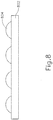
- FIG. 8 depicts a perspective view of an exemplary buttress body (802) in which humidity tolerant adhesive material has been applied in a pattern of discrete, semi-rigid dots (804).
- the discrete, rigid semi-dots (804) may be sized and positioned to correspond with the positioning of staple forming pockets (64) of anvil (60).
- the discrete, semi-rigid dots of adhesive material (804) are may be arranged in four longitudinally extending linear arrays, with each longitudinally extending linear array corresponding the longitudinally arrayed arrangement of staple forming pockets (64) of anvil (60). Alternatively, any other suitable arrangement may be used.
- adding the rigid dots (804) boosts the modulus of the humidity tolerant adhesive material, while having little impact on its cohesive strength.
- FIG. 9 shows how buttress body (902) provides a lattice defining a plurality of cells (908). Due to the presence of cells (908) and the porous nature of buttress body (902), when the humidity tolerant adhesive material (904) is applied to the buttress body (902), it forms a lattice pattern by entering into some of those cells (908), thereby partially infusing buttress body (902) with the adhesive material. In other words, buttress body (902) acts like a sponge absorbing the adhesive material, allowing the adhesive material to deform, surround, and essentially grab hold of the lattice connections within buttress body (902).
- the humidity tolerant adhesive material is initially applied to buttress body (902) when the adhesive material is in a relatively highly viscous form. Buttress body (902) is then heated to decrease the viscosity of the adhesive material, causing the adhesive material to enter some of the cells (908) of buttress body (902). Buttress body (902) is then cooled or allowed to cool, causing the viscosity of the adhesive material to increase back to its previous state. Buttress body (902) may then be heated again as buttress body (902) is being applied to end effector (40) as described above. In some other versions, the adhesive material already has a low enough viscosity to enter cells (908) when the adhesive material is applied, without requiring the adhesive material to be heated.
- the adhesive material may wick into cells (908) of buttress body (902).
- a protective film e.g., polytetrafluoroethylene (PTFE)
- PTFE polytetrafluoroethylene
- de-wetting may occur as a result of moisture being present on the end effector (40) to which the buttress body (102, 112) has been adhered.
- de-wetting may be minimized by one or more steps selected from the group consisting of: drying; priming; absorbing water; and combinations thereof. Each of these steps is explained in further detail below.
- de-wetting may be minimized by drying the end effector (40) prior to adhering a buttress body (102, 112) thereto.
- drying the end effector (40) may be accomplished by applying an absorbent to the end effector (40).
- end effector (40) may be temporary clamped onto an absorbent platform (e.g., comprising a polyacrylate pad) in order to substantially dry underside (65) of anvil (60) and deck (73) of staple cartridge (70) as described in U.S. Patent App. No. 62/209,041 , entitled “Method and Apparatus for Applying a Buttress to an End Effector of a Surgical Stapler," filed August 24, 2015.
- absorbent platform e.g., comprising a polyacrylate pad
- de-wetting may be additionally or alternatively minimized by priming the end effector (40) with a hydrophobic layer prior to adhering a buttress body (102, 112) thereto.
- a sponge with an adhesive -miscible hydrophobe may be clamped onto the end effector (40) to make it temporarily hydrophobic prior to adhering a buttress body (102, 112) thereto.
- adhesive -miscible hydrophobes may be selected from the group consisting of: ethyl citrate; triacetin; triolein; and combinations thereof.
- the adhesive -miscible hydrophobes may be applied as follows.
- One or more adhesive -miscible hydrophobes may be pre-loaded into an open cell foam layer.
- the open cell foam layer may be loaded and squeezed between the buttress bodies (102, 112) after the buttress bodies (102, 112) have been adhered onto the anvil (60) and lower jaw (50) of the end effector (40).
- the adhesive -miscible hydrophobe(s) may migrate from the open cell foam layer, through the buttress bodies (102, 112) to the interface between the humidity tolerant adhesive material and the anvil (60) or staple cartridge (70) of the end effector (40), creating a temporarily hydrophobic environment that may be favorable to maintaining good adhesive properties.
- de-wetting may be additionally or alternatively minimized by coating all or a portion of the end effector (40), e.g. the anvil (60) and/or staple cartridge (70), with a hydrophobic lubricious coating comprising calcium stearate or magnesium stearate.
- de-wetting may be additionally or alternatively minimized by absorbing moisture away from the surface of the end effector (40). In some such versions, this may be accomplished by mixing a hydrocolloid into the humidity tolerant adhesive material at the time that the adhesive is made. Generally it is theorized, but in no way limits the scope of this invention, that hydrocolloids provide the resulting humidity tolerant adhesive material with wet tack characteristics that enable the adhesive material to stick to both wet and dry surfaces. Suitable compositions that may form the hydrocolloid may be selected from the group consisting of: carboxy methylcellulose (CMC); gelatin; hyaluronate; and combinations thereof.
- CMC carboxy methylcellulose
- gelatin hyaluronate
- moisture may additionally or alternatively be absorbed away from the surface of the end effector (40) by adding a hydrophilic block to one of the polymers or co-polymers that form the humidity tolerant adhesive material.
- Suitable hydrophilic blocks may be selected from the group consisting of: polyethylene glycol (PEG); polyvinyl pyrrolidine (PVP); and combinations thereof.
- a series of staples (90) may capture and retain buttress assemblies (100, 110) against layers of tissue (T 1 , T 2 ), thereby securing buttress assemblies (100, 110) to tissue (T 1 , T 2 ).
- tissue-contacting surfaces of one or more buttress assemblies (100, 110) may be treated so that they become lubricious.
- a lubricious buttress body (102, 112) surface may reduce the shear force, i.e., drag force, that is applied between the layers of tissue (T 1 , T 2 ) and buttress assemblies (100, 110).
- Exemplary substances that may be applied to the tissue-contacting surfaces of one or more buttress assemblies (100, 110) to make them lubricious may be selected from the group consisting of: polyethylene glycol 200 (PEG 200); silicone; oil; and combinations thereof.
- forces may additionally or alternatively be reduced by modifying the edges of the buttress body assembly (100, 110).
- modifications of the edges of the buttress body assembly (100, 110) may minimize snagging and/or gripping on the layers of tissue (T 1 , T 2 ) by the buttress assemblies (100, 110) when they are being placed, or are in place, against the layers of tissue (T 1 , T 2 ), and vice versa.
- Useful means of modifying the edges of the buttress body assembly (100, 110) may be selected from the group consisting of: radiusing; chamfering; and combinations thereof.
- a method of applying a buttress to a wet surgical stapler end effector with a humidity tolerant adhesive comprising the steps of: (a) positioning a buttress assembly between an anvil and a staple cartridge of the end effector, wherein the buttress assembly comprises: (i) a buttress body, and (ii) a humidity tolerant adhesive material, wherein the humidity tolerant adhesive material faces either an underside of the anvil or a deck of the staple cartridge, wherein the anvil is in an open position relative to the staple cartridge during the act of positioning the buttress assembly between the anvil and the staple cartridge; (b) moving the anvil toward the staple cartridge; and (c) moving the anvil back to the open position, wherein the buttress assembly is adhered to the underside of the anvil or the deck of the staple cartridge via the humidity tolerant adhesive material with the anvil moved back to the open position, wherein the humidity tolerant adhesive material holds the buttress body to the underside of the anvil or the deck of the staple cartridge for at least five minutes in an environment of 100% relative
- Example 1 The method of Example 1, wherein the humidity tolerant adhesive material holds the buttress body to the underside of the anvil or the deck of the staple cartridge for at least ten minutes in an environment of 100% relative humidity at body temperature after the humidity tolerant adhesive material has been exposed to a relative humidity of from about 20% to about 40% for up to one hour at room temperature.
- Example 3 wherein the poloxamers are selected from the group consisting of: poloxamer 188; Synperonic® PE/P84; poloxamer 124; poloxamer 407; and combinations thereof.
- the humidity tolerant adhesive material comprises a mixture of polyethylene glycol having a molecular weights of from about 200 to about 20,000.
- molecular weight means weight average molecular weight in KDa or g/mol.
- the humidity tolerant adhesive material comprises copolymers selected from the group consisting of: polyethylene-polyethylene glycol copolymers; poly(caprolactone)-glycolide copolymers; and combinations thereof.
- Example 6 wherein the humidity tolerant adhesive material comprises a blend of polyethylene-polyethylene glycol copolymers and poly(caprolactone)-glycolide copolymers in the ratio of from about 40:60 to about 60:40 of polyethylene-polyethylene glycol copolymers to poly(caprolactone)-glycolide copolymers.
- the humidity tolerant adhesive material comprises a block copolymer of polyethylene glycol and poly(caprolactone)-glycolide copolymer.
- a buttress assembly that is configured to temporarily adhere to a wet surgical stapler end effector, the buttress assembly comprising: (a) a buttress body; and (b) humidity tolerant adhesive material, wherein the humidity tolerant adhesive material is applied to at least one side of the buttress body, wherein the humidity tolerant adhesive material is configured to hold the buttress body to an underside of an anvil or a deck of a staple cartridge for at least five minutes in an environment of 100% relative humidity at approximately 37°C.
- Example 11 wherein the humidity tolerant adhesive material is configured to hold the buttress body to the underside of the anvil or the deck of the staple cartridge for at least five minutes in an environment of 100% relative humidity at approximately 37°C after the humidity tolerant adhesive material has been exposed to a relative humidity of from about 20% to about 60% for up to one hour at a temperature between approximately 20°C and approximately 22°C.
- the buttress assembly of any one or more of Examples 11 through 14, wherein the humidity tolerant adhesive material comprises copolymers selected from the group consisting of: polyethylene-polyethylene glycol copolymers; poly(caprolactone)-glycolide copolymers; and combinations thereof.
- the humidity tolerant adhesive material comprises a blend of polyethylene-polyethylene glycol copolymers and poly(caprolactone)-glycolide copolymers in the ratio of from about 40:60 to about 60:40 of polyethylene-polyethylene glycol copolymers to poly(caprolactone)-glycolide copolymers.
- the humidity tolerant adhesive material comprises a block copolymer of polyethylene glycol and poly(caprolactone)-glycolide copolymer.
- a buttress assembly that is configured to temporarily adhere to a wet surgical stapler end effector, the buttress assembly comprising: (a) a buttress body; and (b) humidity tolerant adhesive material, wherein the humidity tolerant adhesive material is applied to at least one side of the buttress body, wherein the humidity tolerant adhesive material is configured to hold the buttress body to an underside of an anvil or a deck of a staple cartridge for at least five minutes in an environment of 100% relative humidity at approximately 37°C, wherein the humidity tolerant adhesive material comprises a combination of solid triglycerides in oil and one or more sorbents.
- any of the various buttress assemblies described herein may be further constructed and operable in accordance with at least some of the teachings of U.S. Patent App. No. 14/667,842 , entitled “Method of Applying a Buttress to a Surgical Stapler,” filed March 25, 2015; U.S. Patent App. No. 14/827,856 , entitled “Implantable Layers for a Surgical Instrument,” filed August 17, 2015; U.S. Patent App. No. 14/871,071 , entitled “Compressible Adjunct with Crossing Spacer Fibers,” filed September 30, 2015; and U.S. Patent App. No.
- any of the various buttress assemblies described herein may be applied to end effector (40) in accordance with at least some of the teachings of U.S. Provisional Patent App. No. 62/209,041 , entitled “Method and Apparatus for Applying a Buttress to End Effector of a Surgical Stapler,” filed August 24, 2015; and/or U.S. Patent App. No. 14/871,131 , entitled “Method for Applying an Implantable Layer to a Fastener Cartridge,” filed September 30, 2015.
- Various suitable ways in which the teachings herein may be combined with various teachings of the above-cited references will be apparent to those of ordinary skill in the art.
- 2012/0199630 entitled “Robotically-Controlled Surgical Instrument with Force-Feedback Capabilities,” published August 9, 2012; U.S. Pub. No. 2012/0132450 , entitled “Shiftable Drive Interface for Robotically-Controlled Surgical Tool,” published May 31, 2012; U.S. Pub. No. 2012/0199633 , entitled “Surgical Stapling Instruments with Cam-Driven Staple Deployment Arrangements,” published August 9, 2012; U.S. Pub. No. 2012/0199631 , entitled “Robotically-Controlled Motorized Surgical End Effector System with Rotary Actuated Closure Systems Having Variable Actuation Speeds,” published August 9, 2012; U.S. Pub. No.
- 2012/0199632 entitled “Robotically-Controlled Surgical Instrument with Selectively Articulatable End Effector,” published August 9, 2012; U.S. Pub. No. 2012/0203247 , entitled “Robotically-Controlled Surgical End Effector System,” published August 9, 2012; U.S. Pub. No. 2012/0211546 , entitled “Drive Interface for Operably Coupling a Manipulatable Surgical Tool to a Robot,” published August 23, 2012; U.S. Pub. No. 2012/0138660 , entitled “Robotically-Controlled Cable-Based Surgical End Effectors,” published June 7, 2012; and/or U.S. Pub. No. 2012/0205421 , entitled “Robotically-Controlled Surgical End Effector System with Rotary Actuated Closure Systems,” published August 16, 2012.
- Versions of the devices described above may be designed to be disposed of after a single use, or they can be designed to be used multiple times. Versions may, in either or both cases, be reconditioned for reuse after at least one use. Reconditioning may include any combination of the steps of disassembly of the device, followed by cleaning or replacement of particular pieces, and subsequent reassembly. In particular, some versions of the device may be disassembled, and any number of the particular pieces or parts of the device may be selectively replaced or removed in any combination. Upon cleaning and/or replacement of particular parts, some versions of the device may be reassembled for subsequent use either at a reconditioning facility, or by a user immediately prior to a procedure.
- reconditioning of a device may utilize a variety of techniques for disassembly, cleaning/replacement, and reassembly. Use of such techniques, and the resulting reconditioned device, are all within the scope of the present application.
- versions described herein may be sterilized before and/or after a procedure.
- the device is placed in a suitable closed and sealed container.
- the container and device may then be placed in a field of radiation that can penetrate the container, such as gamma radiation, x-rays, or high-energy electrons.
- the radiation may kill bacteria on the device and in the container.
- the sterilized device may then be stored in the sterile container for later use.
- a device may also be sterilized using any other technique known in the art, including but not limited to beta or gamma radiation, ethylene oxide, or steam.
Abstract
Description
- In some settings, endoscopic surgical instruments may be preferred over traditional open surgical devices since a smaller incision may reduce the post-operative recovery time and complications. Consequently, some endoscopic surgical instruments may be suitable for placement of a distal end effector at a desired surgical site through the cannula of a trocar. These distal end effectors may engage tissue in a number of ways to achieve a diagnostic or therapeutic effect (e.g., endocutter, grasper, cutter, stapler, clip applier, access device, drug/gene therapy delivery device, and energy delivery device using ultrasonic vibration, RF, laser, etc.). Endoscopic surgical instruments may include a shaft between the end effector and a handle portion, which is manipulated by the clinician. Such a shaft may enable insertion to a desired depth and rotation about the longitudinal axis of the shaft, thereby facilitating positioning of the end effector within the patient. Positioning of an end effector may be further facilitated through inclusion of one or more articulation joints or features, enabling the end effector to be selectively articulated or otherwise deflected relative to the longitudinal axis of the shaft.
- Examples of endoscopic surgical instruments include surgical staplers. Some such staplers are operable to clamp down on layers of tissue, cut through the clamped layers of tissue, and drive staples through the layers of tissue to substantially seal the severed layers of tissue together near the severed ends of the tissue layers. Merely exemplary surgical staplers are disclosed in
U.S. Pat. No. 4,805,823 , entitled "Pocket Configuration for Internal Organ Staplers," issued February 21, 1989;U.S. Pat. No. 5,415,334 , entitled "Surgical Stapler and Staple Cartridge," issued May 16, 1995;U.S. Pat. No. 5,465,895 , entitled "Surgical Stapler Instrument," issued November 14, 1995;U.S. Pat. No. 5,597,107 , entitled "Surgical Stapler Instrument," issued January 28, 1997;U.S. Pat. No. 5,632,432 , entitled "Surgical Instrument," issued May 27, 1997;U.S. Pat. No. 5,673,840 , entitled "Surgical Instrument," issued October 7, 1997;U.S. Pat. No. 5,704,534 , entitled "Articulation Assembly for Surgical Instruments," issued January 6, 1998;U.S. Pat. No. 5,814,055 , entitled "Surgical Clamping Mechanism," issued September 29,1998;U.S. Pat. No. 6,978,921 , entitled "Surgical Stapling Instrument Incorporating an E-Beam Firing Mechanism," issued December 27, 2005;U.S. Pat. No. 7,000,818 , entitled "Surgical Stapling Instrument Having Separate Distinct Closing and Firing Systems," issued February 21,2006;U.S. Pat. No. 7,143,923 , entitled "Surgical Stapling Instrument Having a Firing Lockout for an Unclosed Anvil," issued December 5, 2006;U.S. Pat. No. 7,303,108 , entitled "Surgical Stapling Instrument Incorporating a Multi-Stroke Firing Mechanism with a Flexible Rack," issued December 4, 2007;U.S. Pat. No. 7,367,485 , entitled "Surgical Stapling Instrument Incorporating a Multistroke Firing Mechanism Having a Rotary Transmission," issued May 6, 2008;U.S. Pat. No. 7,380,695 , entitled "Surgical Stapling Instrument Having a Single Lockout Mechanism for Prevention of Firing," issued June 3, 2008;U.S. Pat. No. 7,380,696 , entitled "Articulating Surgical Stapling Instrument Incorporating a Two-Piece E-Beam Firing Mechanism," issued June 3, 2008;U.S. Pat. No. 7,404,508 , entitled "Surgical Stapling and Cutting Device," issued July 29, 2008;U.S. Pat. No. 7,434,715 , entitled "Surgical Stapling Instrument Having Multistroke Firing with Opening Lockout," issued October 14, 2008;U.S. Pat. No. 7,721,930 , entitled "Disposable Cartridge with Adhesive for Use with a Stapling Device," issued May 25, 2010;U.S. Pat. No. 8,408,439 , entitled "Surgical Stapling Instrument with An Articulatable End Effector," issued April 2, 2013; andU.S. Pat. No. 8,453,914 , entitled "Motor-Driven Surgical Cutting Instrument with Electric Actuator Directional Control Assembly," issued June 4, 2013. - While the surgical staplers referred to above are described as being used in endoscopic procedures, it should be understood that such surgical staplers may also be used in open procedures and/or other non-endoscopic procedures. By way of example only, a surgical stapler may be inserted through a thoracotomy, and thereby between a patient's ribs, to reach one or more organs in a thoracic surgical procedure that does not use a trocar as a conduit for the stapler. Such procedures may include the use of the stapler to sever and close a vessel leading to a lung. For instance, the vessels leading to an organ may be severed and closed by a stapler before removal of the organ from the thoracic cavity. Of course, surgical staplers may be used in various other settings and procedures.
- Examples of surgical staplers that may be particularly suited for use through a thoracotomy are disclosed in
U.S. Patent Pub. No. 2014/0243801 , entitled "Surgical Instrument End Effector Articulation Drive with Pinion and Opposing Racks," published August 28, 2014;U.S. Patent Pub. No. 2014/0239041 , entitled "Lockout Feature for Movable Cutting Member of Surgical Instrument," published August 28, 2014;U.S. Patent Pub. No. 2014/0239042 , entitled "Integrated Tissue Positioning and Jaw Alignment Features for Surgical Stapler," published August 28,2014;U.S. Patent Pub. No. 2014/0239036 , entitled "Jaw Closure Feature for End Effector of Surgical Instrument," published August 28, 2014;U.S. Patent Pub. No. 2014/0239040 , entitled "Surgical Instrument with Articulation Lock having a Detenting Binary Spring," published August 28, 2014;U.S. Patent Pub. No. 2014/0239043 , entitled "Distal Tip Features for End Effector of Surgical Instrument," published August 28, 2014;U.S. Patent Pub. No. 2014/0239037 , entitled "Staple Forming Features for Surgical Stapling Instrument," published August 28, 2014;U.S. Patent Pub. No. 2014/0239038 U.S. Patent Pub. No. 2014/0239044 , entitled "Installation Features for Surgical Instrument End Effector Cartridge," published August 28, 2014. - Additional surgical stapling instruments are disclosed in
U.S. Pat. No. 8,801,735 , entitled "Surgical Circular Stapler with Tissue Retention Arrangements," issued August 12, 2014;U.S. Pat. No. 8,141,762 , entitled "Surgical Stapler Comprising a Staple Pocket," issued March 27, 2012;U.S. Pat. No. 8,371,491 , entitled "Surgical End Effector Having Buttress Retention Features," issued February 12, 2013;U.S. Pub. No. 2014/0263563 , entitled "Method and Apparatus for Sealing End-to-End Anastomosis" published September 18, 2014;U.S. Pub. No. 2014/0246473 , entitled "Rotary Powered Surgical Instruments with Multiple Degrees of Freedom," published September 4, 2014;U.S. Pub. No. 2013/0206813 , entitled "Linear Stapler," published August 15, 2013;U.S. Pub. No. 2008/0169328 , entitled "Buttress Material for Use with a Surgical Stapler," published July 17, 2008;U.S. Pat. App. No. 14/300,804 U.S. Pat. App. No. 14/300,811 , entitled "Devices and Methods for Sealing Staples in Tissue"; andU.S. Pat. App. No. 14/498,070 - In some instances, it may be desirable to equip a surgical stapling instrument with a buttress material to reinforce the mechanical fastening of tissue provided by staples. Such a buttress may prevent the applied staples from pulling through tissue and may otherwise reduce a risk of tissue tearing at or near the site of applied staples.
- While various kinds of surgical stapling instruments and associated components have been made and used, it is believed that no one prior to the inventor(s) has made or used the invention described in the appended claims.
- The accompanying drawings, which are incorporated in and constitute a part of this specification, illustrate embodiments of the invention, and, together with the general description of the invention given above, and the detailed description of the embodiments given below, serve to explain the principles of the present invention.
-
FIG. 1 depicts a perspective view of an exemplary articulating surgical stapling instrument; -
FIG. 2 depicts a perspective view of an end effector of the instrument ofFIG. 1 , with the end effector in an open configuration; -
FIG. 3 depicts an exploded perspective view of the end effector ofFIG. 2 ; -
FIG. 4 depicts a perspective view of an exemplary upper buttress and an exemplary lower buttress, each of which may be applied to the end effector ofFIG. 2 ; -
FIG. 5A depicts a cross-sectional end view of a portion of the end effector ofFIG. 2 with a buttress assembly formed by the buttresses ofFIG. 4 applied to the end effector, with tissue positioned between the buttresses in the end effector, and with the anvil in an open position; -
FIG. 5B depicts a cross-sectional end view of the combined end effector and buttress assembly ofFIG. 5A , with tissue positioned between the buttresses in the end effector, and with the anvil in a closed position; -
FIG. 5C depicts a cross-sectional view of a staple and the buttress assembly ofFIG. 5A having been secured to the tissue by the end effector ofFIG. 2 ; -
FIG. 6 depicts a perspective view of staples and the buttress assembly ofFIG. 5A having been secured to the tissue by the end effector ofFIG. 2 ; -
FIG. 7 depicts a perspective view of an exemplary alternative buttress assembly; -
FIG. 8 depicts a cross-sectional side view of another exemplary alternative buttress assembly; and -
FIG. 9 depicts a cross-sectional side view of another exemplary alternative buttress assembly. - The drawings are not intended to be limiting in any way, and it is contemplated that various embodiments of the invention may be carried out in a variety of other ways, including those not necessarily depicted in the drawings. The accompanying drawings incorporated in and forming a part of the specification illustrate several aspects of the present invention, and together with the description serve to explain the principles of the invention; it being understood, however, that this invention is not limited to the precise arrangements shown.
- The following description of certain examples of the invention should not be used to limit the scope of the present invention. Other examples, features, aspects, embodiments, and advantages of the invention will become apparent to those skilled in the art from the following description, which is by way of illustration, one of the best modes contemplated for carrying out the invention. As will be realized, the invention is capable of other different and obvious aspects, all without departing from the invention. Accordingly, the drawings and descriptions should be regarded as illustrative in nature and not restrictive.
-
FIG. 1 depicts an exemplary surgical stapling and severing instrument (10) that includes a handle assembly (20), a shaft assembly (30), and an end effector (40). End effector (40) and the distal portion of shaft assembly (30) are sized for insertion, in a nonarticulated state as depicted inFIG. 1 , through a trocar cannula to a surgical site in a patient for performing a surgical procedure. By way of example only, such a trocar may be inserted in a patient's abdomen, between two of the patient's ribs, or elsewhere. In some settings, instrument (10) is used without a trocar. For instance, end effector (40) and the distal portion of shaft assembly (30) may be inserted directly through a thoracotomy or other type of incision. It should be understood that terms such as "proximal" and "distal" are used herein with reference to a clinician gripping handle assembly (20) of instrument (10). Thus, end effector (40) is distal with respect to the more proximal handle assembly (20). It will be further appreciated that for convenience and clarity, spatial terms such as "vertical" and "horizontal" are used herein with respect to the drawings. However, surgical instruments are used in many orientations and positions, and these terms are not intended to be limiting and absolute. - As shown in
FIG. 1 , handle assembly (20) of the present example comprises pistol grip (22), a closure trigger (24), and a firing trigger (26). Each trigger (24, 26) is selectively pivotable toward and away from pistol grip (22) as will be described in greater detail below. Handle assembly (20) further includes a removable battery pack (28). These components will also be described in greater detail below. Of course, handle assembly (20) may have a variety of other components, features, and operabilities, in addition to or in lieu of any of those noted above. Other suitable configurations for handle assembly (20) will be apparent to those of ordinary skill in the art in view of the teachings herein. - As shown in
FIGS. 1-2 , shaft assembly (30) of the present example comprises an outer closure tube (32), an articulation section (34), and a closure ring (36), which is further coupled with end effector (40). Closure tube (32) extends along the length of shaft assembly (30). Closure ring (36) is positioned distal to articulation section (34). Closure tube (32) and closure ring (36) are configured to translate longitudinally relative to handle assembly (20). Longitudinal translation of closure tube (32) is communicated to closure ring (36) via articulation section (34). Exemplary features that may be used to provide longitudinal translation of closure tube (32) and closure ring (36) will be described in greater detail below. - Articulation section (34) is operable to laterally deflect closure ring (36) and end effector (40) laterally away from the longitudinal axis (LA) of shaft assembly (30) at a desired angle (α). In the present example, articulation is controlled through an articulation control knob (35) which is located at the proximal end of shaft assembly (30). Closure ring (36) and end effector (40) pivot about an axis that is perpendicular to the longitudinal axis (LA) of shaft assembly (30) in response to rotation of knob (35). Articulation section (34) is configured to communicate longitudinal translation of closure tube (32) to closure ring (36), regardless of whether articulation section (34) is in a straight configuration or an articulated configuration. By way of example only, articulation section (34) and/or articulation control knob (35) may be constructed and operable in accordance with at least some of the teachings of
U.S. Pub. No. 2014/0243801 , entitled "Surgical Instrument End Effector Articulation Drive with Pinion and Opposing Racks," published August 28, 2014; and/orU.S. Pat. App. No. 14/314,125 - As shown in
FIG. 1 , shaft assembly (30) of the present example further includes a rotation knob (31). Rotation knob (31) is operable to rotate the entire shaft assembly (30) and end effector (40) relative to handle assembly (20) about the longitudinal axis (LA) of shaft assembly (30). Of course, shaft assembly (30) may have a variety of other components, features, and operabilities, in addition to or in lieu of any of those noted above. By way of example only, at least part of shaft assembly (30) is constructed in accordance with at least some of the teachings ofU.S. Pub. No. 2014/0239038 , entitled "Surgical Instrument with Multi-Diameter Shaft," published August 28, 2014. Other suitable configurations for shaft assembly (30) will be apparent to those of ordinary skill in the art in view of the teachings herein. - As also shown in
FIGS. 1-3 , end effector (40) of the present example includes a lower jaw (50) and a pivotable anvil (60). Anvil (60) includes a pair of integral, outwardly extending pins (66) that are disposed in corresponding curved slots (54) of lower jaw (50). Anvil (60) is pivotable toward and away from lower jaw (50) between an open position (shown inFIG. 2 ) and a closed position (shown inFIG. 1 ). Use of the term "pivotable" (and similar terms with "pivot" as a base) should not be read as necessarily requiring pivotal movement about a fixed axis. For instance, in the present example, anvil (60) pivots about an axis that is defined by pins (66), which slide along curved slots (54) of lower jaw (50) as anvil (60) moves toward lower jaw (50). In such versions, the pivot axis translates along the path defined by slots (54) while anvil (60) simultaneously pivots about that axis. In addition or in the alternative, the pivot axis may slide along slots (54) first, with anvil (60) then pivoting about the pivot axis after the pivot axis has slid a certain distance along the slots (54). It should be understood that such sliding/translating pivotal movement is encompassed within terms such as "pivot," "pivots," "pivotal," "pivotable," "pivoting," and the like. Of course, some versions may provide pivotal movement of anvil (60) about an axis that remains fixed and does not translate within a slot or channel, etc. - As best seen in
FIG. 3 , lower jaw (50) of the present example defines a channel (52) that is configured to receive a staple cartridge (70). Staple cartridge (70) may be inserted into channel (52), end effector (40) may be actuated, and then staple cartridge (70) may be removed and replaced with another staple cartridge (70). Lower jaw (50) thus releasably retains staple cartridge (70) in alignment with anvil (60) for actuation of end effector (40). In some versions, lower jaw (50) is constructed in accordance with at least some of the teachings ofU.S. Pub. No. 2014/0239044 , entitled "Installation Features for Surgical Instrument End Effector Cartridge," published August 28, 2014. Other suitable forms that lower jaw (50) may take will be apparent to those of ordinary skill in the art in view of the teachings herein. - As best seen in
FIGS. 2-3 , staple cartridge (70) of the present example comprises a cartridge body (71) and a tray (76) secured to the underside of cartridge body (71). The upper side of cartridge body (71) presents a deck (73), against which tissue may be compressed when anvil (60) is in a closed position. Cartridge body (71) further defines a longitudinally extending channel (72) and a plurality of staple pockets (74). A staple (90) is positioned in each staple pocket (74). A staple driver (75) is also positioned in each staple pocket (74), underneath a corresponding staple (90), and above tray (76). As will be described in greater detail below, staple drivers (75) are operable to translate upwardly in staple pockets (74) to thereby drive staples (90) upwardly through staple pockets (74) and into engagement with anvil (60). Staple drivers (75) are driven upwardly by a wedge sled (78), which is captured between cartridge body (71) and tray (76), and which translates longitudinally through cartridge body (71). - Wedge sled (78) includes a pair of obliquely angled cam surfaces (79), which are configured to engage staple drivers (75) and thereby drive staple drivers (75) upwardly as wedge sled (78) translates longitudinally through cartridge (70). For instance, when wedge sled (78) is in a proximal position, staple drivers (75) are in downward positions and staples (90) are located in staple pockets (74). As wedge sled (78) is driven to the distal position by a translating knife member (80), wedge sled (78) drives staple drivers (75) upwardly, thereby driving staples (90) out of staple pockets (74) and into staple forming pockets (64) that are formed in the underside (65) of anvil (60). Thus, staple drivers (75) translate along a vertical dimension as wedge sled (78) translates along a horizontal dimension.
- In some versions, staple cartridge (70) is constructed and operable in accordance with at least some of the teachings of U.
U.S. Pub. No. 2014/0239042 , entitled "Integrated Tissue Positioning and Jaw Alignment Features for Surgical Stapler," published August 28, 2014. In addition or in the alternative, staple cartridge (70) may be constructed and operable in accordance with at least some of the teachings ofU.S. Pub. No. 2014/0239044 , entitled "Installation Features for Surgical Instrument End Effector Cartridge," published August 28, 2014. Other suitable forms that staple cartridge (70) may take will be apparent to those of ordinary skill in the art in view of the teachings herein. - As best seen in
FIG. 2 , anvil (60) of the present example comprises a longitudinally extending channel (62) and a plurality of staple forming pockets (64). Channel (62) is configured to align with channel (72) of staple cartridge (70) when anvil (60) is in a closed position. Each staple forming pocket (64) is positioned to lie over a corresponding staple pocket (74) of staple cartridge (70) when anvil (60) is in a closed position. Staple forming pockets (64) are configured to deform the legs of staples (90) when staples (90) are driven through tissue and into anvil (60). In particular, staple forming pockets (64) are configured to bend the legs of staples (90) to secure the formed staples (90) in the tissue. Anvil (60) may be constructed in accordance with at least some of the teachings ofU.S. Pub. No. 2014/0239042 , entitled "Integrated Tissue Positioning and Jaw Alignment Features for Surgical Stapler," published August 28, 2014; at least some of the teachings ofU.S. Pub. No. 2014/0239036 , entitled "Jaw Closure Feature for End Effector of Surgical Instrument," published August 28, 2014; and/or at least some of the teachings ofU.S. Pub. No. 2014/0239037 , entitled "Staple Forming Features for Surgical Stapling Instrument," published August 28, 2014. Other suitable forms that anvil (60) may take will be apparent to those of ordinary skill in the art in view of the teachings herein. - In the present example, a knife member (80) is configured to translate through end effector (40). As best seen in
FIG. 3 , knife member (80) is secured to the distal end of a firing beam (82), which extends through a portion of shaft assembly (30). As best seen inFIG. 2 , knife member (80) is positioned in channels (62, 72) of anvil (60) and staple cartridge (70). Knife member (80) includes a distally presented cutting edge (84) that is configured to sever tissue that is compressed between anvil (60) and deck (73) of staple cartridge (70) as knife member (80) translates distally through end effector (40). As noted above, knife member (80) also drives wedge sled (78) distally as knife member (80) translates distally through end effector (40), thereby driving staples (90) through tissue and against anvil (60) into formation. - In the present example, anvil (60) is driven toward lower jaw (50) by advancing closure ring (36) distally relative to end effector (40). Closure ring (36) cooperates with anvil (60) through a camming action to drive anvil (60) toward lower jaw (50) in response to distal translation of closure ring (36) relative to end effector (40). Similarly, closure ring (36) may cooperate with anvil (60) to open anvil (60) away from lower jaw (50) in response to proximal translation of closure ring (36) relative to end effector (40). By way of example only, closure ring (36) and anvil (60) may interact in accordance with at least some of the teachings of
U.S. Pub. No. 2014/0239036 , entitled "Jaw Closure Feature for End Effector of Surgical Instrument," published August 28, 2014; and/or in accordance with at least some of the teachings ofU.S. Patent App. No. 14/314,108 - As noted above, handle assembly (20) includes a pistol grip (22) and a closure trigger (24). As also noted above, anvil (60) is closed toward lower jaw (50) in response to distal advancement of closure ring (36). In the present example, closure trigger (24) is pivotable toward pistol grip (22) to drive closure tube (32) and closure ring (36) distally. Various suitable components that may be used to convert pivotal movement of closure trigger (24) toward pistol grip (22) into distal translation of closure tube (32) and closure ring (36) relative to handle assembly (20) will be apparent to those of ordinary skill in the art in view of the teachings herein.
- Also in the present example, instrument (10) provides motorized control of firing beam (82). In particular, instrument (10) includes motorized components that are configured to drive firing beam (82) distally in response to pivoting of firing trigger (26) toward pistol grip (22). In some versions, a motor (not shown) is contained in pistol grip (22) and receives power from battery pack (28). This motor is coupled with a transmission assembly (not shown) that converts rotary motion of a drive shaft of the motor into linear translation of firing beam (82). By way of example only, the features that are operable to provide motorized actuation of firing beam (82) may be configured and operable in accordance with at least some of the teachings of
U.S. Pat. No. 8,210,411 , entitled "Motor-Driven Surgical Instrument," issued July 3, 2012;U.S. Pat. No. 8,453,914 , entitled "Motor-Driven Surgical Cutting Instrument with Electric Actuator Directional Control Assembly," issued June 4, 2013; and/orU.S. Patent App. No. 14/226,142 - It should also be understood that any other components or features of instrument (10) may be configured and operable in accordance with any of the various references cited herein. Additional exemplary modifications that may be provided for instrument (10) will be described in greater detail below. Various suitable ways in which the below teachings may be incorporated into instrument (10) will be apparent to those of ordinary skill in the art. Similarly, various suitable ways in which the below teachings may be combined with various teachings of the references cited herein will be apparent to those of ordinary skill in the art. It should therefore be understood that the teachings below may be readily incorporated into the various instruments taught in the various references that are cited herein. It should also be understood that the below teachings are not limited to instrument (10) or devices taught in the references cited herein. The below teachings may be readily applied to various other kinds of instruments, including instruments that would not be classified as surgical staplers. Various other suitable devices and settings in which the below teachings may be applied will be apparent to those of ordinary skill in the art in view of the teachings herein.
- In some instances, it may be desirable to equip end effector (40) with a buttress material to reinforce the mechanical fastening of tissue provided by staples (90). Such a buttress may prevent the applied staples (90) from pulling through the tissue and may otherwise reduce a risk of tissue tearing at or near the site of applied staples (90). In addition to or as an alternative to providing structural support and integrity to a line of staples (90), a buttress may provide various other kinds of effects such as spacing or gap-filling, administration of therapeutic agents, and/or other effects. In some instances, a buttress may be provided on deck (73) of staple cartridge (70). In some other instances, a buttress may be provided on the surface of anvil (60) that faces staple cartridge (70). It should also be understood that a first buttress may be provided on deck (73) of staple cartridge (70) while a second buttress is provided on anvil (60) of the same end effector (40). Various examples of forms that a buttress may take will be described in greater detail below. Various ways in which a buttress may be secured to a staple cartridge (70) or an anvil (60) will also be described in greater detail below.
-
FIG. 4 shows an exemplary pair of buttress assemblies (100, 110) with a basic composition. Buttress assembly (100) of this example comprises a buttress body (102) and an upper adhesive layer (104). Similarly, buttress assembly (110) comprises a buttress body (112) and a lower adhesive layer (114). In the present example, each buttress body (102, 112) comprises a strong yet flexible material configured to structurally support a line of staples (90). By way of example only, each buttress body (102, 112) may comprise a mesh of polyglactin 910 material by Ethicon, Inc. of Somerville, New Jersey. Alternatively, any other suitable materials or combinations of materials may be used in addition to or as an alternative to polyglactin 910 material to form each buttress body (102, 112). Each buttress body (102, 112) may take any other suitable form and may be constructed of any other suitable material(s). By way of further example only, each buttress body (102, 112) may comprise one or more of the following: NEOVEIL absorbable PGA felt by Gunze Limited, of Kyoto, Japan; SEAMGUARD polyglycolic acid:trimethylene carbonate (PGA:TMC) reinforcement material by W.L. Gore & Associates, Inc., of Flagstaff, Arizona; PERI-STRIPS DRY with VERITAS Collagen Matrix (PSDV) reinforcement material, by Baxter Healthcare Corporation of Deerfield, Illinois; BIODESIGN biologic graft material by Cook Medical, Bloomington, Indiana; and/or SURGICEL NU-KNIT hemostat material by Ethicon, Inc. of Somerville, New Jersey. Still other suitable materials that may be used to form each buttress body (102, 112) will be apparent to those of ordinary skill in the art in view of the teachings herein. - In addition or in the alternative, each buttress body (102, 112) may comprise a material including, for example, a hemostatic agent such as fibrin to assist in coagulating blood and reduce bleeding at the severed and/or stapled surgical site along tissue (90). As another merely illustrative example, each buttress body (102, 112) may comprise other adjuncts or hemostatic agents such as thrombin may be used such that each buttress body (102, 112) may assist to coagulate blood and reduce the amount of bleeding at the surgical site. Other adjuncts or reagents that may be incorporated into each buttress body (102, 112) may further include but are not limited to medical fluid or matrix components. Merely illustrative examples of materials that may be used to form each buttress body (102, 112), as well as materials that may be otherwise incorporated into each buttress body (102, 112), are disclosed in
U.S. Patent App. No. 14/667,842 - By way of further example only, each buttress body (102, 112) may be constructed in accordance with at least some of the teachings of
U.S. Patent Pub. No. 2012/0241493 , entitled "Tissue Thickness Compensator Comprising Controlled Release and Expansion," published September 27, 2012;U.S. Patent Pub. No. 2013/0068816 , entitled "Surgical Instrument and Buttress Material," published March 21, 2013;U.S. Patent Pub. No. 2013/0062391 , entitled "Surgical Instrument with Fluid Fillable Buttress," published March 14, 2013;U.S. Patent Pub. No. 2013/0068820 , entitled "Fibrin Pad Matrix with Suspended Heat Activated Beads of Adhesive," published March 21, 2013;U.S. Patent Pub. No. 2013/0082086 , entitled "Attachment of Surgical Staple Buttress to Cartridge," published April 4, 2013;U.S. Patent Pub. No. 2013/0037596 , entitled "Device for Applying Adjunct in Endoscopic Procedure," published February 14, 2013;U.S. Patent Pub. No. 2013/0062393 , entitled "Resistive Heated Surgical Staple Cartridge with Phase Change Sealant," published March 14, 2013;U.S. Patent Pub. No. 2013/0075446 , entitled "Surgical Staple Assembly with Hemostatic Feature," published March 28, 2013;U.S. Patent Pub. No. 2013/0062394 , entitled "Surgical Staple Cartridge with Self-Dispensing Staple Buttress," published March 14, 2013;U.S. Patent Pub. No. 2013/0075445 , entitled "Anvil Cartridge for Surgical Fastening Device," published March 28, 2013;U.S. Patent Pub. No. 2013/0075447 , entitled "Adjunct Therapy for Applying Hemostatic Agent," published March 28,2013;U.S. Patent Pub. No. 2013/0256367 , entitled "Tissue Thickness Compensator Comprising a Plurality of Medicaments," published October 3, 2013;U.S. Patent Application No. 14/300,954 U.S. Patent App. No. 14/827,856 U.S. Patent Application No. 14/840,613 U.S. Patent App. No. 14/871,071 U.S. Patent App. No. 14/871,131 - In the present example, adhesive layer (104) is provided on buttress body (102) in order to adhere buttress body (102) to underside (65) of anvil (60). Similarly, adhesive layer (114) is provided on buttress body (112) in order to adhere buttress body (112) to deck (73) of staple cartridge (70). Adherence of the buttress body (102) to underside (65) of anvil (60) or to deck (73) of staple cartridge (70) can occur through a variety of mechanisms including but not limited to a pressure sensitive adhesive. In some versions, each adhesive layer (104, 114) comprise a pressure sensitive adhesive material. Examples of various suitable materials that may be used to form adhesive layers (104, 114) are disclosed in
U.S. Patent App. No. 14/667,842 - As noted above, a buttress assembly (100) may include a layer (104, 114) of adhesive material (or other form of adhesive material) that adheres buttress body (102, 112) to either underside (65) of anvil (60) or deck (73) of staple cartridge (70). Such an adhesive material may provide proper positioning of buttress body (102, 112) before and during actuation of end effector (40); then allow buttress body (102, 112) to separate from end effector (40) after end effector (40) has been actuated, without causing damage to buttress body (102, 112) that is substantial enough to compromise the proper subsequent functioning of buttress body (102, 112).
-
FIGS. 5A-5C show a sequence where an end effector (40) that has been loaded with buttress assemblies (100, 110) is actuated to drive staples (90) through two apposed layers of tissue (T1, T2), with buttress assemblies (100, 110) being secured to the same layers of tissue (T1, T2) by staples (90). In particular,FIG. 5A shows layers of tissue (T1, T2) positioned between anvil (60) and staple cartridge (70), with anvil (60) in the open position. Buttress assembly (100) is adhered to the underside (65) of anvil (60) via adhesive layer (104); while buttress assembly (110) is adhered to deck (73) of staple cartridge (70) via adhesive layer (114). Layers of tissue (T1, T2) are thus interposed between buttress assemblies (100, 110). Next, trigger (24) is pivoted toward pistol grip (22) to drive closure tube (32) and closure ring (36) distally. This drives anvil (60) to the closed position as shown inFIG. 5B . At this stage, layers of tissue (T1, T2) are compressed between anvil (60) and staple cartridge (70), with buttress assemblies (100, 110) engaging opposite surfaces of tissue layers (T1, T2). End effector (40) is then actuated as described above, driving staple (90) through buttress assemblies (100, 110) and tissue (90). As shown inFIG. 5C , crown (92) of driven staple (90) captures and retains buttress assembly (110) against layer of tissue (T2). Deformed legs (94) of staple (90) capture and retain buttress assembly (100) against layer of tissue (T1). - It should be understood that a series of staples (90) will similarly capture and retain buttress assemblies (100, 110) against layers of tissue (T1, T2), thereby securing buttress assemblies (100, 110) to tissue (T1, T2) as shown in
FIG. 6 . As end effector (40) is pulled away from tissue (90) after deploying staples (90) and buttress assemblies (100, 110), buttress assemblies (100, 110) disengage end effector (40), such that buttress assemblies (100, 110) remain secured to tissue (T1, T2) with staples (90). Buttress tissue (T1, T2) thus provide structural reinforcement to the lines of staples (90). As can also be seen inFIG. 6 , knife member (80) also cuts through a centerline of buttress tissue assemblies (100, 110), separating each buttress assemblies (100, 110) into a corresponding pair of sections, such that each section remains secured to a respective severed region of tissue (T1, T2). - In the foregoing example, buttress assembly (100) is sized to span across the full width of underside (65), such that buttress assembly (100) spans across channel (62). Thus, knife member (80) cuts through buttress assembly (100) during actuation of end effector (40) as described above. In some other examples, such as those described below, buttress assembly (100) is provided in two separate, laterally spaced apart portions, with one portion being disposed on underside (65) on one side of channel (62) and another portion being disposed on underside (65) on the other side of channel (62). In such versions, buttress assembly (100) does not span across channel (62), such that knife member (80) does not cut through buttress assembly (100) during actuation of end effector (40).
- Likewise, buttress assembly (110) may be sized to span across the full width of deck (73), such that buttress assembly (110) spans across channel (72), and such that knife member (80) cuts through buttress assembly (110) during actuation of end effector (40) as described above. Alternatively, buttress assembly (110) may be provided in two separate, laterally spaced apart portions, with one portion being disposed on deck (73) on one side of channel (72) and another portion being disposed on deck (73) on the other side of channel (72), such that buttress assembly (110) does not span across channel (72), and such that knife member (80) does not cut through buttress assembly (110) during actuation of end effector (40).
- One of ordinary skill in the art will recognize that, during some uses of instrument (10), the operator may need to actuate end effector (40) several times within a patient. Each actuation may require the operator to remove end effector (40) from the patient, reload a new staple cartridge (70) into lower jaw (50), apply new buttress assemblies (100, 110) to anvil (60) and staple cartridge (70), and then insert the reloaded end effector (40) into the patient. Each time end effector (40) is removed from the patient, anvil (60) may be substantially wet with bodily fluids from the patient and/or other fluids in the surgical field. Even when a new cartridge (70) is installed in lower jaw (50), the new cartridge (70) may also receive fluids from other portions of end effector (40) that were already wet. The presence of fluids on underside (65) of anvil (60) and/or on deck (73) of staple cartridge (70) may make it difficult to adhere buttress assemblies (100, 110) to anvil (60) and staple cartridge (70). The following examples relate to various compositions and configurations that may be used to promote proper adhesion of buttress assemblies (100, 110) to anvil (60) and staple cartridge (70) when buttress assemblies (100, 110) to anvil (60) and staple cartridge (70) are wet with one or more fluids.
- In some surgical applications, it may be desirable to provide a buttress body (102, 112) with one or more humidity tolerant adhesive materials that will at least temporarily adhere to a wet end effector (40), particularly when it is being used intraoperatively. In some instances, humidity tolerant adhesive materials may provide for temporary attachment of a buttress body (102, 112) to the wet deck (73) of staple cartridge (70) or the wet underside (65) of anvil (60). A humidity tolerant adhesive material is defined herein as an adhesive material that holds a buttress body (102, 112) in place on an anvil (60) or staple cartridge (70) for at least five minutes in an environment of 100% relative humidity (e.g., in a patient's body, at a normal body temperature of approximately 37°C), preferably after the buttress body (102, 112) has been exposed to a relative humidity of from about 20% to about 60% for up to one hour at room temperature (e.g., between approximately 20°C and approximately 22°C). In some instances, a humidity tolerant adhesive material may hold a buttress body (102, 112) in place on an anvil (60) or staple cartridge (70) for at least ten minutes in an environment of 100% relative humidity (e.g., in a patient's body, at a normal body temperature of approximately 37°C), preferably after the buttress body (102, 112) has been exposed to a relative humidity of from about 20% to about 60% for up to one hour at room temperature (e.g., between approximately 20°C and approximately 22°C). A pressure sensitive humidity tolerant adhesive material is defined herein as a humidity tolerant adhesive material that can be transferred from a delivery device onto an anvil (60) or staple cartridge (70) by the pressure respectively exerted by the anvil (60) or staple cartridge (70).
- As noted above,
FIG. 4 shows buttress assemblies (100, 110) that each comprises a buttress body (102, 112) and an adhesive layer (104, 114). Adhesive layers (104, 114) respectively provide for temporary attachment of the buttress bodies (102, 112) to underside (65) of anvil (60) and deck (73) of staple cartridge (70). It should be understood that the humidity tolerant adhesive material need not necessarily constitute a separate adhesive layer (104, 114) that is discretely identifiable as being different from a layer defined by buttress body (102, 112). Examples of humidity tolerant adhesive materials that may be otherwise integrated onto or into a buttress body (102, 112) are described in further detail below. - In some instances, the humidity tolerant adhesive materials (e.g., one or more of layers (104, 114)) for a buttress body (102, 112), comprise polymers that are either bioabsorbable or of a molecular weight that is sufficiently low so as to be cleared from the patient's body (e.g., less than approximately 30,000 KDa). Various physiomechanical properties of polymers may be modified in order to provide different adhesive properties. Such variable characteristics include but are not limited to the following: copolymer composition; copolymer architecture (e.g., random vs. block configurations, polymer branching, etc.); glass transition temperature (Tg); molecular weight; crystallinity; sequence distribution; copolymer chain composition; melting temperature (Tm); solubility or dissolution rate; rheological properties; surface tension; and combinations thereof. Several exemplary combinations of these variables will be provided below, though it should be understood that these examples are merely illustrative.
- In addition or in the alternative to the aforementioned modifications to the physiomechanical properties of polymers, some exemplary humidity tolerant adhesive materials may comprise polymers that are combined with sorbents. Useful sorbents may be selected from the group consisting of: polysaccharides such as cellulose; cellulose derivatives, e.g., sodium carboxymethylcellulose (Na-CMC); starch; starch derivates; natural gums, e.g., agar and alginates; chitosan; pectin; gelatin; and combinations thereof. In some examples, a hydrocolloid of one or more sorbents may be mixed with the polymers. In some examples, the humidity tolerant adhesive material comprises a blend of sorbent and polymer in a ratio in a range of 70:30 sorbent to polymer, more particularly in a range of 50:50 sorbent to polymer, more preferably in a range of 10:90 sorbent to polymer. Generally it is theorized, but in no way limits the scope of this invention, that sorbents may act to absorb moisture away from the surface interface between the humidity tolerant adhesive material and the surface to which it is adhered (e.g., a wet end effector (40)), and to maintain the adherence of the buttress body (102, 112) to said surface until such time as the buttress body (102, 112) is deployed or released from end effector (40) (see, for example,
FIG. 5C ). - One of the aforementioned physiomechanical properties of polymers is glass transition temperature (Tg). Glass transition temperature is the temperature at which the mechanical properties of a copolymer change dramatically from a flowable adhesive to a brittle plastic. It may thus be of importance that the glass transition temperature (Tg) is sufficiently below the operating temperature of the humidity tolerant adhesive material in order to allow for sufficient polymer chain mobility. The melting temperature (Tm) of a polymer may be referred to as the "first-order transition," which is where the polymer changes state from solid to liquid. Crystalline polymers have a true melting point, which is the temperature at which the crystallites melt and the total mass of plastic becomes liquid. Amorphous polymers do not have a true melting point, but they do have a first-order transition wherein their mechanical behavior transitions from a rubbery nature to viscous rubbery flow. Suitable polymers for use in humidity tolerant adhesive materials may be semi-crystalline, i.e., they may have both amorphous and crystalline segments. Suitable polymers may have a melting point that is sufficiently above the operating temperature of the humidity tolerant adhesive material to maintain cohesive strength and to provide dimensional stability of the applied humidity tolerant adhesive material. As used herein, the glass transition temperature of a polymer means the temperature at which the Gibbs free energy is such that the activation energy for the cooperative movement of 50 elements of the polymer is exceeded.
- The molecular weight of non-bioabsorbable polymers should be high enough to provide mechanical strength to the resulting adhesive material in order to avoid cohesive failure, yet low enough that they can be cleared by the patient's body. In the case of biodegradable polymers, an upper limit on molecular weight may not be required to provide polymer breakdown products are small enough to be cleared by the patient's body.
- The solubility or dissolution rate of polymers in the aqueous environments that may be encountered during surgery depend upon a number of polymer characteristics including, but not limited to: polymer composition; polymer architecture; degree of cross-linking; block length; crystallinity; molecular weight; branching; and combinations thereof. In illustrative examples described below, certain polymers and co-polymers are chosen and combined with these characteristics in mind in order to decrease the dissolution rate of the resulting humidity tolerant adhesive materials that are of use for adhering a buttress body (102, 112) to a wet end effector (40) during surgery, and maintaining the adherence of the buttress body to the wet end effector (40) until such time as the buttress body (102, 112) is deployed or released from end effector (40) (see, for example,
FIG. 5C ). - The surface tension and rheology of polymers present in a humidity tolerant adhesive material may also impact its adhesive properties. For example, if there is a sufficiently large mismatch between the surface tension of the polymers and the surfaces to which it will adhere, adhesion between the two may be energetically unfavorable. Similarly, the rheological properties of the polymer such as bulk modulus may be such that the humidity tolerant adhesive material can flow to conform to the surface topography of the end effector (40), while at the same time providing sufficient integrity to maintain cohesive strength and resist shearing and peeling of the buttress body (102, 112) from the end effector (40).
- In some examples, the humidity tolerant adhesive materials (e.g., one or more of layers (104, 114)) for a buttress body (102, 112) may comprise a blend of "plastic fats", more particularly, poloxamers. In illustrative examples, the blend of poloxamers may comprise a blend of poloxamers selected from the group consisting of: poloxamer 188, for example Kolliphor® P188 from BASF (Florham Park, NJ); Synperonic® PE/P84 from Croda Inc. (Edison, NJ); poloxamer 124, for example Pluronic® L44 from BASF (Florham Park, NJ); poloxamer 407, for example Pluronic® F-127 from BASF (Florham Park, NJ); and combinations thereof. Preferably, the poloxamers are of National Formulary grade. The resulting poloxamer-based humidity tolerant adhesive materials may be putty-like materials with a relatively low crystallinity and low glass transition temperature (Tg). Generally it is theorized, but in no way limits the scope of this invention, that the presence of polypropylene oxide repeat units in the backbone of the poloxamers provides for a poloxamer blend having a slower dissolution rate, which may desirably provide for humidity tolerant adhesive materials having a greater humidity (i.e., wetness) tolerance. In turn, a buttress body (102, 112), to which poloxamer-based adhesive materials have been applied, may desirably remain adhered to a wet end effector (40) of a surgical stapling instrument (10) during a surgical procedure until such time as buttress body (102, 112) is deployed (see, for example,
FIG. 5C ). - In some examples, the humidity tolerant adhesive materials comprise a poloxamer blend of poloxamer 188 and Synperonic® PE/P84 in a molar ratio in the range of from 1:3 to 1:4 of poloxamer 188 to Synperonic® PE/P84. In some other examples, humidity tolerant adhesive materials comprise a poloxamer blend of poloxamer 188 and poloxamer 124 in a molar ratio in the range of from about 1:1 to about 1:4, more particularly from about 1:1.5 to about 1:3, of poloxamer 188 to poloxamer 124. In yet some other examples, the poloxamer blend may comprise a blend of poloxamer 407 and poloxamer 124 in a molar ratio in the range of from about 1:1, to about 1:5, more particularly from about 1:1.5 to about 1:3 of poloxamer 407 to poloxamer 124.
- In yet some other examples, the poloxamers may be combined with non-ionic surfactants to modify the hydrophobicity of the resulting humidity tolerant adhesive material. In some such examples, the poloxamers may be combined with non-ionic surfactants selected from the group consisting of: polysorbates; polyethylene glycol hexadecyl ether, for
example Brij 52 from Croda Inc. (Edison, NJ); sorbitane monooleate, for example,Span® 80 from Sigma Aldrich (Saint Louis, MO); and combinations thereof. - In each of the foregoing exemplary poloxamer blends, it may be important to control the crystallite size of the poloxamers in order to achieve the desirable adhesive characteristics in the resulting humidity tolerant adhesive material.
- In some examples, the humidity tolerant adhesive materials (e.g., one or more of layers (104, 114)) for a buttress body (102, 112) comprise polyethylene glycol (PEG) or polyethylene-polyethylene glycol co-polymers (PE-co-PEG). The resulting humidity tolerant adhesive materials may be putty-like, malleable and extrudable.
- In yet further examples, the pressure sensitive humidity tolerant adhesive materials comprise, or consist essentially of, polyethylene-polyethylene glycol co-polymers (PE-co-PEG) with a molecular weight that is sufficiently low so as to be cleared from the patient's body (e.g., less than approximately 30,000 KDa).
- In yet further examples, the humidity tolerant adhesive materials comprise a blend of polyethylene-polyethylene glycol copolymers (PE-co-PEG) and poly(caprolactone)-glycolide copolymers (PCL/PGA) in the ratio of about 40:60 PCL:PGA, preferably in a ratio of about 50:50 PCL:PGA, more preferably in a ratio of about 60:40 PCL:PGA. Such a blend may have low crystallinity and may even be near amorphous.
- In yet further examples, the humidity tolerant adhesive materials comprise a blend of polyethylene glycol having different molecular weights that is in turn blended with a polymer or co-polymer selected from the group consisting of: poloxamers; poly(caprolactone)-glycolide copolymers (PCL/PGA); lactide (PLA); and combinations thereof. By way of example only, the blend may include polyethylene glycol 3350 (PEG 3350), polyethylene glycol 400 (PEG 400), and/or other polyethylene glycols.
- In yet further examples, the humidity tolerant adhesive materials comprise a block copolymer of polyethylene glycol 20,000 (PEG 20,000) and poly(caprolactone)-glycolide copolymers (PCL/PGA) that are characterized by a molarratio of 65:35 poly(caprolactone) (PCL) to glycolide (PGA). The resulting blends may have a relatively high molecular weight and lower solubility.
- As yet another merely illustrative example, the humidity tolerant adhesive materials comprise a blend of other water soluble copolymers with poloxamers or PEG, with a molecular weight low enough to be cleared from the patient's body. Such a blend may be substituted for a component of any of the blends described above; or for the entirety of any of the blends described above. By way of further example only, the polymer(s) in such a blend may be biodegradable such as PCL/PGA, etc.
- In some examples, the humidity tolerant adhesive materials (e.g., one or more of layers (104, 114)) for a buttress body (102, 112) comprise "plastic fats" comprising solid triglycerides in oil. In some illustrative examples, such humidity tolerant adhesive materials further comprise sorbents. Useful sorbents may be selected from the group consisting of: polysaccharides such as cellulose; cellulose derivatives, e.g., sodium carboxymethylcellulose (Na-CMC); starch; starch derivates; natural gums, e.g., agar and alginates; chitosan; pectin; gelatin; and combinations thereof. Useful triglycerides may be selected from the group consisting of: decanoyl glycerides; octanoyl glycerides; and combinations thereof-for example, Miglyol® 810, 812, 818 and 829 from Caesar & Loretz GMBH (Hilden, DE). Useful oils may be selected from the group consisting of: bis-diglyceryl polyacyladipate-1; glycerol trioheptanoate; and combinations thereof-for example, Softisan® 645 and Spezialöl 107 from Cremer Care (Hamburg, GE). The resulting humidity tolerant adhesive materials may desirably provide for good adhesion to end effector (40) and good spreading properties.
- In some examples, the humidity tolerant adhesive materials (e.g., one or more of layers (104, 114)) for a buttress body (102, 112) comprise hydrocolloid gels. In some illustrative examples, useful hydrocolloid gels may be selected from the group consisting of gels comprising: chitosan; carboxymethyl cellulose (CMC); ethyl cellulose; hydroxypropylmethyl cellulose; gelatin; and combinations thereof. The resulting humidity tolerant adhesive materials may have a relatively high water binding capacity.
- Patterning of humidity tolerant adhesive material on a buttress body (102, 112) may be utilized to impact the strength of the adhesive bond of the buttress body (102, 112) to an end effector (40), particularly a wet end effector (40). In exemplary embodiments in which it is desired to reduce the overall adhesion of a buttress body (102, 112) to an end effector (40) so that it may be more easily deployed or released from end effector (40) (as in
FIG. 5C for example), the humidity tolerant adhesive material may be applied to a buttress body (102, 112) in a pattern selected from the group consisting of: stripes; discrete dots; lattices; and combinations thereof. Conversely, in exemplary embodiments in which it is desired to increase the overall adhesion of a buttress body (102, 112) to an end effector (40) so that it less readily deployed or released from end effector (40) (as inFIG. 5C for example), the humidity tolerant adhesive materials may be applied in an adhesive layer (104, 114), that extends continuously along the entire surface of buttress body (102, 112). -
FIG. 7 shows an exemplary buttress body (702) in which humidity tolerant adhesive material is applied to the buttress body (702) in a pattern of obliquely oriented stripes (704). Generally it is theorized, but in no way limits the scope of this invention, that oblique stripes (704) present a continuous line to resist side loads that may be encountered during surgery by a buttress body (704) that has been adhered to an end effector (40). In addition, it is believed that oblique stripes (704) minimize the percentage of area that is coated by the adhesive material along the axis of the buttress body (702) in the direction of the forces that will release the buttress body (702), so as allow the buttress body (702) to be readily deployed from the end effector (40) during a surgical procedure (as inFIG. 5C for example). In the present example, oblique stripes (704) are oblique in the sense that stripes (704) extend along paths that are obliquely oriented relative to axes that are parallel to the longitudinal axis of buttress body (702). In some exemplary variations, stripes (704) extend along axial paths that are parallel to the longitudinal axis of buttress body (702). -
FIG. 8 depicts a perspective view of an exemplary buttress body (802) in which humidity tolerant adhesive material has been applied in a pattern of discrete, semi-rigid dots (804). The discrete, rigid semi-dots (804) may be sized and positioned to correspond with the positioning of staple forming pockets (64) of anvil (60). Thus, the discrete, semi-rigid dots of adhesive material (804) are may be arranged in four longitudinally extending linear arrays, with each longitudinally extending linear array corresponding the longitudinally arrayed arrangement of staple forming pockets (64) of anvil (60). Alternatively, any other suitable arrangement may be used. Generally it is theorized, but in no way limits the scope of this invention, that adding the rigid dots (804) boosts the modulus of the humidity tolerant adhesive material, while having little impact on its cohesive strength. -
FIG. 9 shows how buttress body (902) provides a lattice defining a plurality of cells (908). Due to the presence of cells (908) and the porous nature of buttress body (902), when the humidity tolerant adhesive material (904) is applied to the buttress body (902), it forms a lattice pattern by entering into some of those cells (908), thereby partially infusing buttress body (902) with the adhesive material. In other words, buttress body (902) acts like a sponge absorbing the adhesive material, allowing the adhesive material to deform, surround, and essentially grab hold of the lattice connections within buttress body (902). - In some instances, the humidity tolerant adhesive material is initially applied to buttress body (902) when the adhesive material is in a relatively highly viscous form. Buttress body (902) is then heated to decrease the viscosity of the adhesive material, causing the adhesive material to enter some of the cells (908) of buttress body (902). Buttress body (902) is then cooled or allowed to cool, causing the viscosity of the adhesive material to increase back to its previous state. Buttress body (902) may then be heated again as buttress body (902) is being applied to end effector (40) as described above. In some other versions, the adhesive material already has a low enough viscosity to enter cells (908) when the adhesive material is applied, without requiring the adhesive material to be heated. In other words, the adhesive material may wick into cells (908) of buttress body (902). In some such versions, a protective film (e.g., polytetrafluoroethylene (PTFE)) may be applied over the adhesive material to protect and/or contain the adhesive material before buttress body (902) is applied to end effector (40). Other suitable ways in which buttress assembly (902) may be formed and provided are disclosed in
U.S. Patent App. No. 14/667,842 - In some surgical applications, it may be desirable to reduce the spontaneous separation of a buttress body (102, 112) from the humidity tolerant adhesive material that has been applied thereto. Such spontaneous separation or "de-wetting" may occur as a result of moisture being present on the end effector (40) to which the buttress body (102, 112) has been adhered. In some instances, de-wetting may be minimized by one or more steps selected from the group consisting of: drying; priming; absorbing water; and combinations thereof. Each of these steps is explained in further detail below.
- In some instances, de-wetting may be minimized by drying the end effector (40) prior to adhering a buttress body (102, 112) thereto. In exemplary embodiments, drying the end effector (40) may be accomplished by applying an absorbent to the end effector (40). For instance, end effector (40) may be temporary clamped onto an absorbent platform (e.g., comprising a polyacrylate pad) in order to substantially dry underside (65) of anvil (60) and deck (73) of staple cartridge (70) as described in
U.S. Patent App. No. 62/209,041 - In some instances, de-wetting may be additionally or alternatively minimized by priming the end effector (40) with a hydrophobic layer prior to adhering a buttress body (102, 112) thereto. In exemplary embodiments, a sponge with an adhesive -miscible hydrophobe may be clamped onto the end effector (40) to make it temporarily hydrophobic prior to adhering a buttress body (102, 112) thereto. In exemplary embodiments, adhesive -miscible hydrophobes may be selected from the group consisting of: ethyl citrate; triacetin; triolein; and combinations thereof.
- In some versions, the adhesive -miscible hydrophobes may be applied as follows. One or more adhesive -miscible hydrophobes may be pre-loaded into an open cell foam layer. The open cell foam layer may be loaded and squeezed between the buttress bodies (102, 112) after the buttress bodies (102, 112) have been adhered onto the anvil (60) and lower jaw (50) of the end effector (40). During squeezing of the open cell foam layer, at least a portion of the adhesive -miscible hydrophobe(s) may migrate from the open cell foam layer, through the buttress bodies (102, 112) to the interface between the humidity tolerant adhesive material and the anvil (60) or staple cartridge (70) of the end effector (40), creating a temporarily hydrophobic environment that may be favorable to maintaining good adhesive properties.
- In some instances, de-wetting may be additionally or alternatively minimized by coating all or a portion of the end effector (40), e.g. the anvil (60) and/or staple cartridge (70), with a hydrophobic lubricious coating comprising calcium stearate or magnesium stearate.
- In some instances, de-wetting may be additionally or alternatively minimized by absorbing moisture away from the surface of the end effector (40). In some such versions, this may be accomplished by mixing a hydrocolloid into the humidity tolerant adhesive material at the time that the adhesive is made. Generally it is theorized, but in no way limits the scope of this invention, that hydrocolloids provide the resulting humidity tolerant adhesive material with wet tack characteristics that enable the adhesive material to stick to both wet and dry surfaces. Suitable compositions that may form the hydrocolloid may be selected from the group consisting of: carboxy methylcellulose (CMC); gelatin; hyaluronate; and combinations thereof.
- In some instances, moisture may additionally or alternatively be absorbed away from the surface of the end effector (40) by adding a hydrophilic block to one of the polymers or co-polymers that form the humidity tolerant adhesive material. Suitable hydrophilic blocks may be selected from the group consisting of: polyethylene glycol (PEG); polyvinyl pyrrolidine (PVP); and combinations thereof.
- As noted above in reference to
FIG. 6 , a series of staples (90) may capture and retain buttress assemblies (100, 110) against layers of tissue (T1, T2), thereby securing buttress assemblies (100, 110) to tissue (T1, T2). In some surgical procedures, it may be desirable to reduce forces that are exerted against the buttress assemblies (100, 110) when they are being placed, or are in place, against the layers of tissue (T1, T2). Such a reduction in force may allow for better adhesion of the buttress bodies (102, 112) to the end effector (40). In addition, or in the alternative, it may be desirable to reduce forces that may damage the layers of tissue (T1, T2) that are to be, or have been, secured. In illustrative examples, this may be accomplished by treating the tissue-contacting surfaces of one or more buttress assemblies (100, 110) so that they become lubricious. Generally it is theorized, but in no way limits the scope of this invention, that a lubricious buttress body (102, 112) surface may reduce the shear force, i.e., drag force, that is applied between the layers of tissue (T1, T2) and buttress assemblies (100, 110). Exemplary substances that may be applied to the tissue-contacting surfaces of one or more buttress assemblies (100, 110) to make them lubricious may be selected from the group consisting of: polyethylene glycol 200 (PEG 200); silicone; oil; and combinations thereof. - In further illustrative examples, forces may additionally or alternatively be reduced by modifying the edges of the buttress body assembly (100, 110). Generally it is theorized, but in no way limits the scope of this invention, that such modifications of the edges of the buttress body assembly (100, 110) may minimize snagging and/or gripping on the layers of tissue (T1, T2) by the buttress assemblies (100, 110) when they are being placed, or are in place, against the layers of tissue (T1, T2), and vice versa. Useful means of modifying the edges of the buttress body assembly (100, 110) may be selected from the group consisting of: radiusing; chamfering; and combinations thereof.
- In addition to the foregoing, it should also be understood that any of the various buttress assemblies described herein may be further constructed and operable in accordance with at least some of the teachings of
U.S. Patent App. No. 14/667,842 - The following examples relate to various non-exhaustive ways in which the teachings herein may be combined or applied. It should be understood that the following examples are not intended to restrict the coverage of any claims that may be presented at any time in this application or in subsequent filings of this application. No disclaimer is intended. The following examples are being provided for nothing more than merely illustrative purposes. It is contemplated that the various teachings herein may be arranged and applied in numerous other ways. It is also contemplated that some variations may omit certain features referred to in the below examples. Therefore, none of the aspects or features referred to below should be deemed critical unless otherwise explicitly indicated as such at a later date by the inventors or by a successor in interest to the inventors. If any claims are presented in this application or in subsequent filings related to this application that include additional features beyond those referred to below, those additional features shall not be presumed to have been added for any reason relating to patentability.
- A method of applying a buttress to a wet surgical stapler end effector with a humidity tolerant adhesive, the method comprising the steps of: (a) positioning a buttress assembly between an anvil and a staple cartridge of the end effector, wherein the buttress assembly comprises: (i) a buttress body, and (ii) a humidity tolerant adhesive material, wherein the humidity tolerant adhesive material faces either an underside of the anvil or a deck of the staple cartridge, wherein the anvil is in an open position relative to the staple cartridge during the act of positioning the buttress assembly between the anvil and the staple cartridge; (b) moving the anvil toward the staple cartridge; and (c) moving the anvil back to the open position, wherein the buttress assembly is adhered to the underside of the anvil or the deck of the staple cartridge via the humidity tolerant adhesive material with the anvil moved back to the open position, wherein the humidity tolerant adhesive material holds the buttress body to the underside of the anvil or the deck of the staple cartridge for at least five minutes in an environment of 100% relative humidity.
- The method of Example 1, wherein the humidity tolerant adhesive material holds the buttress body to the underside of the anvil or the deck of the staple cartridge for at least ten minutes in an environment of 100% relative humidity at body temperature after the humidity tolerant adhesive material has been exposed to a relative humidity of from about 20% to about 40% for up to one hour at room temperature.
- The method of any one or more of Examples 1 through 2, wherein the humidity tolerant adhesive material comprises a blend of poloxamers.
- The method of Example 3, wherein the poloxamers are selected from the group consisting of: poloxamer 188; Synperonic® PE/P84; poloxamer 124; poloxamer 407; and combinations thereof.
- The method of any one or more of Examples 1 through 4, wherein the humidity tolerant adhesive material comprises a mixture of polyethylene glycol having a molecular weights of from about 200 to about 20,000. As used herein, molecular weight means weight average molecular weight in KDa or g/mol.
- The method of any one or more of Examples 1 through 5, wherein the humidity tolerant adhesive material comprises copolymers selected from the group consisting of: polyethylene-polyethylene glycol copolymers; poly(caprolactone)-glycolide copolymers; and combinations thereof.
- The method of Example 6, wherein the humidity tolerant adhesive material comprises a blend of polyethylene-polyethylene glycol copolymers and poly(caprolactone)-glycolide copolymers in the ratio of from about 40:60 to about 60:40 of polyethylene-polyethylene glycol copolymers to poly(caprolactone)-glycolide copolymers.
- The method of any one or more of Examples 1 through 7, wherein the humidity tolerant adhesive material comprises a block copolymer of polyethylene glycol and poly(caprolactone)-glycolide copolymer.
- The method of any one or more of Examples 1 through 8, wherein the humidity tolerant adhesive material comprises triglycerides.
- The method of any one or more of Examples 1 through 9, wherein the humidity tolerant adhesive material comprises a hydrocolloid gel.
- A buttress assembly that is configured to temporarily adhere to a wet surgical stapler end effector, the buttress assembly comprising: (a) a buttress body; and (b) humidity tolerant adhesive material, wherein the humidity tolerant adhesive material is applied to at least one side of the buttress body, wherein the humidity tolerant adhesive material is configured to hold the buttress body to an underside of an anvil or a deck of a staple cartridge for at least five minutes in an environment of 100% relative humidity at approximately 37°C.
- The buttress assembly of Example 11, wherein the humidity tolerant adhesive material is configured to hold the buttress body to the underside of the anvil or the deck of the staple cartridge for at least five minutes in an environment of 100% relative humidity at approximately 37°C after the humidity tolerant adhesive material has been exposed to a relative humidity of from about 20% to about 60% for up to one hour at a temperature between approximately 20°C and approximately 22°C.
- The buttress assembly of any one or more of Examples 11 through 12, wherein the humidity tolerant adhesive material comprises a blend of poloxamers.
- The buttress assembly of any one or more of Examples 11 through 13, wherein the humidity tolerant adhesive material comprises a mixture of polyethylene glycol having a molecular weights of from about 200 to about 20,000.
- The buttress assembly of any one or more of Examples 11 through 14, wherein the humidity tolerant adhesive material comprises copolymers selected from the group consisting of: polyethylene-polyethylene glycol copolymers; poly(caprolactone)-glycolide copolymers; and combinations thereof.
- The method of any one or more of Examples 11 through 15, wherein the humidity tolerant adhesive material comprises a blend of polyethylene-polyethylene glycol copolymers and poly(caprolactone)-glycolide copolymers in the ratio of from about 40:60 to about 60:40 of polyethylene-polyethylene glycol copolymers to poly(caprolactone)-glycolide copolymers.
- The buttress assembly of any one or more of Examples 11 through 16, the humidity tolerant adhesive material comprises a block copolymer of polyethylene glycol and poly(caprolactone)-glycolide copolymer.
- The buttress assembly of any one or more of Examples 11 through 17, wherein the humidity tolerant adhesive material comprises triglycerides.
- The buttress assembly of any one or more of Examples 11 through 18, wherein the wherein the humidity tolerant adhesive material comprises a hydrocolloid gel.
- A buttress assembly that is configured to temporarily adhere to a wet surgical stapler end effector, the buttress assembly comprising: (a) a buttress body; and (b) humidity tolerant adhesive material, wherein the humidity tolerant adhesive material is applied to at least one side of the buttress body, wherein the humidity tolerant adhesive material is configured to hold the buttress body to an underside of an anvil or a deck of a staple cartridge for at least five minutes in an environment of 100% relative humidity at approximately 37°C, wherein the humidity tolerant adhesive material comprises a combination of solid triglycerides in oil and one or more sorbents.
- It should be understood that any one or more of the teachings, expressions, embodiments, examples, etc. described herein may be combined with any one or more of the other teachings, expressions, embodiments, examples, etc. that are described herein. The above-described teachings, expressions, embodiments, examples, etc. should therefore not be viewed in isolation relative to each other. Various suitable ways in which the teachings herein may be combined will be readily apparent to those of ordinary skill in the art in view of the teachings herein. Such modifications and variations are intended to be included within the scope of the claims.
- In addition to the foregoing, it should also be understood that any of the various buttress assemblies described herein may be further constructed and operable in accordance with at least some of the teachings of
U.S. Patent App. No. 14/667,842 U.S. Patent App. No. 14/827,856 U.S. Patent App. No. 14/871,071 U.S. Patent App. No. 14/871,131 U.S. Provisional Patent App. No. 62/209,041 U.S. Patent App. No. 14/871,131 - Versions of the devices described above may have application in conventional medical treatments and procedures conducted by a medical professional, as well as application in robotic-assisted medical treatments and procedures. By way of example only, various teachings herein may be readily incorporated into a robotic surgical system such as the DAVINCI™ system by Intuitive Surgical, Inc., of Sunnyvale, California. Similarly, those of ordinary skill in the art will recognize that various teachings herein may be readily combined with various teachings of any of the following:
U.S. Pat. No. 5,792,135 , entitled "Articulated Surgical Instrument For Performing Minimally Invasive Surgery With Enhanced Dexterity and Sensitivity," issued August 11, 1998;U.S. Pat. No. 5,817,084 , entitled "Remote Center Positioning Device with Flexible Drive," issued October 6, 1998;U.S. Pat. No. 5,878,193 , entitled "Automated Endoscope System for Optimal Positioning," issued March 2, 1999;U.S. Pat. No. 6,231,565 , entitled "Robotic Arm DLUS for Performing Surgical Tasks," issued May 15,2001;U.S. Pat. No. 6,783,524 , entitled "Robotic Surgical Tool with Ultrasound Cauterizing and Cutting Instrument," issued August 31, 2004;U.S. Pat. No. 6,364,888 , entitled "Alignment of Master and Slave in a Minimally Invasive Surgical Apparatus," issued April 2, 2002;U.S. Pat. No. 7,524,320 , entitled "Mechanical Actuator Interface System for Robotic Surgical Tools," issued April 28,2009;U.S. Pat. No. 7,691,098 , entitled "Platform Link Wrist Mechanism," issued April 6, 2010;U.S. Pat. No. 7,806,891 , entitled "Repositioning and Reorientation of Master/Slave Relationship in Minimally Invasive Telesurgery," issued October 5, 2010;U.S. Pub. No. 2013/0012957 , entitled "Automated End Effector Component Reloading System for Use with a Robotic System, published January 10, 2013;U.S. Pub. No. 2012/0199630 , entitled "Robotically-Controlled Surgical Instrument with Force-Feedback Capabilities," published August 9, 2012;U.S. Pub. No. 2012/0132450 , entitled "Shiftable Drive Interface for Robotically-Controlled Surgical Tool," published May 31, 2012;U.S. Pub. No. 2012/0199633 , entitled "Surgical Stapling Instruments with Cam-Driven Staple Deployment Arrangements," published August 9, 2012;U.S. Pub. No. 2012/0199631 , entitled "Robotically-Controlled Motorized Surgical End Effector System with Rotary Actuated Closure Systems Having Variable Actuation Speeds," published August 9, 2012;U.S. Pub. No. 2012/0199632 , entitled "Robotically-Controlled Surgical Instrument with Selectively Articulatable End Effector," published August 9, 2012;U.S. Pub. No. 2012/0203247 , entitled "Robotically-Controlled Surgical End Effector System," published August 9, 2012;U.S. Pub. No. 2012/0211546 , entitled "Drive Interface for Operably Coupling a Manipulatable Surgical Tool to a Robot," published August 23, 2012;U.S. Pub. No. 2012/0138660 , entitled "Robotically-Controlled Cable-Based Surgical End Effectors," published June 7, 2012; and/orU.S. Pub. No. 2012/0205421 , entitled "Robotically-Controlled Surgical End Effector System with Rotary Actuated Closure Systems," published August 16, 2012. - Versions of the devices described above may be designed to be disposed of after a single use, or they can be designed to be used multiple times. Versions may, in either or both cases, be reconditioned for reuse after at least one use. Reconditioning may include any combination of the steps of disassembly of the device, followed by cleaning or replacement of particular pieces, and subsequent reassembly. In particular, some versions of the device may be disassembled, and any number of the particular pieces or parts of the device may be selectively replaced or removed in any combination. Upon cleaning and/or replacement of particular parts, some versions of the device may be reassembled for subsequent use either at a reconditioning facility, or by a user immediately prior to a procedure. Those skilled in the art will appreciate that reconditioning of a device may utilize a variety of techniques for disassembly, cleaning/replacement, and reassembly. Use of such techniques, and the resulting reconditioned device, are all within the scope of the present application.
- By way of example only, versions described herein may be sterilized before and/or after a procedure. In one sterilization technique, the device is placed in a suitable closed and sealed container. The container and device may then be placed in a field of radiation that can penetrate the container, such as gamma radiation, x-rays, or high-energy electrons. The radiation may kill bacteria on the device and in the container. The sterilized device may then be stored in the sterile container for later use. A device may also be sterilized using any other technique known in the art, including but not limited to beta or gamma radiation, ethylene oxide, or steam.
- Having shown and described various embodiments of the present invention, further adaptations of the methods and systems described herein may be accomplished by appropriate modifications by one of ordinary skill in the art without departing from the scope of the present invention. Several of such potential modifications have been mentioned, and others will be apparent to those skilled in the art. For instance, the examples, embodiments, geometrics, materials, dimensions, ratios, steps, and the like discussed above are illustrative and are not required. Accordingly, the scope of the present invention should be considered in terms of the following claims and is understood not to be limited to the details of structure and operation shown and described in the specification and drawings.
Claims (15)
- A method of applying a buttress to a wet surgical stapler end effector with a humidity tolerant adhesive, the method comprising the steps of:(a) positioning a buttress assembly between an anvil and a staple cartridge of the end effector, wherein the buttress assembly comprises:(i) a buttress body, and(ii) a humidity tolerant adhesive material,wherein the humidity tolerant adhesive material faces either an underside of
the anvil or a deck of the staple cartridge,
wherein the anvil is in an open position relative to the staple cartridge during
the act of positioning the buttress assembly between the anvil and the staple cartridge;(b) moving the anvil toward the staple cartridge; and(c) moving the anvil back to the open position, wherein the buttress assembly is adhered to the underside of the anvil or the deck of the staple cartridge via the humidity tolerant adhesive material with the anvil moved back to the open position,wherein the humidity tolerant adhesive material holds the buttress body to the underside of the anvil or the deck of the staple cartridge for at least five minutes in an environment of 100% relative humidity. - The method of claim 1, wherein the humidity tolerant adhesive material holds the buttress body to the underside of the anvil or the deck of the staple cartridge for at least five minutes in an environment of 100% relative humidity at body temperature after the humidity tolerant adhesive material has been exposed to a relative humidity of from about 20% to about 60% for up to one hour at room temperature.
- The method of claim 1 or claim 2, wherein the humidity tolerant adhesive material comprises a blend of poloxamers.
- The method of claim 3, wherein the poloxamers are selected from the group consisting of: poloxamer 188; Synperonic® PE/P84; poloxamer 124; poloxamer 407; and combinations thereof.
- The method of any one of claims 1 to 4, wherein the humidity tolerant adhesive material comprises a mixture of polyethylene glycol having a molecular weights of from about 200 to about 20,000.
- A buttress assembly that is configured to temporarily adhere to a wet surgical stapler end effector, the buttress assembly comprising:(a) a buttress body; and(b) humidity tolerant adhesive material, wherein the humidity tolerant adhesive material is applied to at least one side of the buttress body, wherein the humidity tolerant adhesive material is configured to hold the buttress body to an underside of an anvil or a deck of a staple cartridge for at least five minutes in an environment of 100% relative humidity at approximately 37°C.
- The buttress assembly of claim 6, wherein the humidity tolerant adhesive material is configured to hold the buttress body to the underside of the anvil or the deck of the staple cartridge for at least five minutes in an environment of 100% relative humidity at approximately 37°C after the humidity tolerant adhesive material has been exposed to a relative humidity of from about 20% to about 60% for up to one hour at a temperature between approximately 20°C and approximately 22°C.
- The buttress assembly of claim 6 or claim 7, wherein the humidity tolerant adhesive material comprises a blend of poloxamers.
- The buttress assembly of any one of claims 6 to 8, wherein the humidity tolerant adhesive material comprises a mixture of polyethylene glycol having a molecular weights of from about 200 to about 20,000.
- The method of any one of claims 1 to 5, or the buttress assembly of any one of claims 6 to 9, wherein the humidity tolerant adhesive material comprises copolymers selected from the group consisting of: polyethylene-polyethylene glycol copolymers; poly(caprolactone)-glycolide copolymers; and combinations thereof.
- The method of any one of claims 1 to 5 or 10, or the buttress assembly of any one of claims 6 to 10, wherein the humidity tolerant adhesive material comprises a blend of polyethylene-polyethylene glycol copolymers and poly(caprolactone)-glycolide copolymers in the ratio of from about 40:60 to about 60:40 of polyethylene-polyethylene glycol copolymers to poly(caprolactone)-glycolide copolymers.
- The method of any one of claims 1 to 5, 10 or 11, or the buttress assembly of any one of claims 6 to 11, wherein the humidity tolerant adhesive material comprises a block copolymer of polyethylene glycol and poly(caprolactone)-glycolide copolymer.
- The method of any one of claims 1 to 5, 10, 11 or 12, or the buttress assembly of any one of claims 6 to 12, wherein the humidity tolerant adhesive material comprises triglycerides.
- The method of any one of claims 1 to 5, 10, 11, 12 or 13, or the buttress assembly of any one of claims 6 to 13, wherein the humidity tolerant adhesive material comprises a hydrocolloid gel.
- A buttress assembly that is configured to temporarily adhere to a wet surgical stapler end effector, the buttress assembly comprising:(a) a buttress body; and(b) humidity tolerant adhesive material, wherein the humidity tolerant adhesive material is applied to at least one side of the buttress body, wherein the humidity tolerant adhesive material is configured to hold the buttress body to an underside of an anvil or a deck of a staple cartridge for at least five minutes in an environment of 100% relative humidity at approximately 37°C, wherein the humidity tolerant adhesive material comprises a combination of solid triglycerides in oil and one or more sorbents.
Applications Claiming Priority (1)
| Application Number | Priority Date | Filing Date | Title |
|---|---|---|---|
| US14/926,057 US10517592B2 (en) | 2015-10-29 | 2015-10-29 | Surgical stapler buttress assembly with adhesion to wet end effector |
Publications (2)
| Publication Number | Publication Date |
|---|---|
| EP3162298A1 true EP3162298A1 (en) | 2017-05-03 |
| EP3162298B1 EP3162298B1 (en) | 2024-03-27 |
Family
ID=57209333
Family Applications (1)
| Application Number | Title | Priority Date | Filing Date |
|---|---|---|---|
| EP16196246.9A Active EP3162298B1 (en) | 2015-10-29 | 2016-10-28 | Surgical stapler buttress assembly with adhesion to wet end effector |
Country Status (5)
| Country | Link |
|---|---|
| US (4) | US10517592B2 (en) |
| EP (1) | EP3162298B1 (en) |
| JP (1) | JP6847941B2 (en) |
| CN (1) | CN108348252B (en) |
| WO (1) | WO2017074846A1 (en) |
Cited By (2)
| Publication number | Priority date | Publication date | Assignee | Title |
|---|---|---|---|---|
| EP3530213A3 (en) * | 2018-02-22 | 2019-10-16 | Covidien LP | Surgical buttresses for surgical stapling apparatus |
| WO2022208297A1 (en) * | 2021-03-30 | 2022-10-06 | Cilag Gmbh International | Implantable adjuncts having adjustable degradation profile |
Families Citing this family (346)
| Publication number | Priority date | Publication date | Assignee | Title |
|---|---|---|---|---|
| US20070084897A1 (en) | 2003-05-20 | 2007-04-19 | Shelton Frederick E Iv | Articulating surgical stapling instrument incorporating a two-piece e-beam firing mechanism |
| US9060770B2 (en) | 2003-05-20 | 2015-06-23 | Ethicon Endo-Surgery, Inc. | Robotically-driven surgical instrument with E-beam driver |
| US11890012B2 (en) | 2004-07-28 | 2024-02-06 | Cilag Gmbh International | Staple cartridge comprising cartridge body and attached support |
| US8215531B2 (en) | 2004-07-28 | 2012-07-10 | Ethicon Endo-Surgery, Inc. | Surgical stapling instrument having a medical substance dispenser |
| US10159482B2 (en) | 2005-08-31 | 2018-12-25 | Ethicon Llc | Fastener cartridge assembly comprising a fixed anvil and different staple heights |
| US11484312B2 (en) | 2005-08-31 | 2022-11-01 | Cilag Gmbh International | Staple cartridge comprising a staple driver arrangement |
| US11246590B2 (en) | 2005-08-31 | 2022-02-15 | Cilag Gmbh International | Staple cartridge including staple drivers having different unfired heights |
| US7934630B2 (en) | 2005-08-31 | 2011-05-03 | Ethicon Endo-Surgery, Inc. | Staple cartridges for forming staples having differing formed staple heights |
| US9237891B2 (en) | 2005-08-31 | 2016-01-19 | Ethicon Endo-Surgery, Inc. | Robotically-controlled surgical stapling devices that produce formed staples having different lengths |
| US7669746B2 (en) | 2005-08-31 | 2010-03-02 | Ethicon Endo-Surgery, Inc. | Staple cartridges for forming staples having differing formed staple heights |
| US20070106317A1 (en) | 2005-11-09 | 2007-05-10 | Shelton Frederick E Iv | Hydraulically and electrically actuated articulation joints for surgical instruments |
| US20120292367A1 (en) | 2006-01-31 | 2012-11-22 | Ethicon Endo-Surgery, Inc. | Robotically-controlled end effector |
| US7845537B2 (en) | 2006-01-31 | 2010-12-07 | Ethicon Endo-Surgery, Inc. | Surgical instrument having recording capabilities |
| US11224427B2 (en) | 2006-01-31 | 2022-01-18 | Cilag Gmbh International | Surgical stapling system including a console and retraction assembly |
| US20110024477A1 (en) | 2009-02-06 | 2011-02-03 | Hall Steven G | Driven Surgical Stapler Improvements |
| US8708213B2 (en) | 2006-01-31 | 2014-04-29 | Ethicon Endo-Surgery, Inc. | Surgical instrument having a feedback system |
| US8186555B2 (en) | 2006-01-31 | 2012-05-29 | Ethicon Endo-Surgery, Inc. | Motor-driven surgical cutting and fastening instrument with mechanical closure system |
| US7753904B2 (en) | 2006-01-31 | 2010-07-13 | Ethicon Endo-Surgery, Inc. | Endoscopic surgical instrument with a handle that can articulate with respect to the shaft |
| US11793518B2 (en) | 2006-01-31 | 2023-10-24 | Cilag Gmbh International | Powered surgical instruments with firing system lockout arrangements |
| US11278279B2 (en) | 2006-01-31 | 2022-03-22 | Cilag Gmbh International | Surgical instrument assembly |
| US8820603B2 (en) | 2006-01-31 | 2014-09-02 | Ethicon Endo-Surgery, Inc. | Accessing data stored in a memory of a surgical instrument |
| US20110290856A1 (en) | 2006-01-31 | 2011-12-01 | Ethicon Endo-Surgery, Inc. | Robotically-controlled surgical instrument with force-feedback capabilities |
| US8992422B2 (en) | 2006-03-23 | 2015-03-31 | Ethicon Endo-Surgery, Inc. | Robotically-controlled endoscopic accessory channel |
| US8322455B2 (en) | 2006-06-27 | 2012-12-04 | Ethicon Endo-Surgery, Inc. | Manually driven surgical cutting and fastening instrument |
| US10568652B2 (en) | 2006-09-29 | 2020-02-25 | Ethicon Llc | Surgical staples having attached drivers of different heights and stapling instruments for deploying the same |
| US8684253B2 (en) | 2007-01-10 | 2014-04-01 | Ethicon Endo-Surgery, Inc. | Surgical instrument with wireless communication between a control unit of a robotic system and remote sensor |
| US8652120B2 (en) | 2007-01-10 | 2014-02-18 | Ethicon Endo-Surgery, Inc. | Surgical instrument with wireless communication between control unit and sensor transponders |
| US11291441B2 (en) | 2007-01-10 | 2022-04-05 | Cilag Gmbh International | Surgical instrument with wireless communication between control unit and remote sensor |
| US8540128B2 (en) | 2007-01-11 | 2013-09-24 | Ethicon Endo-Surgery, Inc. | Surgical stapling device with a curved end effector |
| US11039836B2 (en) | 2007-01-11 | 2021-06-22 | Cilag Gmbh International | Staple cartridge for use with a surgical stapling instrument |
| US8727197B2 (en) | 2007-03-15 | 2014-05-20 | Ethicon Endo-Surgery, Inc. | Staple cartridge cavity configuration with cooperative surgical staple |
| US8931682B2 (en) | 2007-06-04 | 2015-01-13 | Ethicon Endo-Surgery, Inc. | Robotically-controlled shaft based rotary drive systems for surgical instruments |
| US11857181B2 (en) | 2007-06-04 | 2024-01-02 | Cilag Gmbh International | Robotically-controlled shaft based rotary drive systems for surgical instruments |
| US7753245B2 (en) | 2007-06-22 | 2010-07-13 | Ethicon Endo-Surgery, Inc. | Surgical stapling instruments |
| US11849941B2 (en) | 2007-06-29 | 2023-12-26 | Cilag Gmbh International | Staple cartridge having staple cavities extending at a transverse angle relative to a longitudinal cartridge axis |
| US7866527B2 (en) | 2008-02-14 | 2011-01-11 | Ethicon Endo-Surgery, Inc. | Surgical stapling apparatus with interlockable firing system |
| US8573465B2 (en) | 2008-02-14 | 2013-11-05 | Ethicon Endo-Surgery, Inc. | Robotically-controlled surgical end effector system with rotary actuated closure systems |
| US8636736B2 (en) | 2008-02-14 | 2014-01-28 | Ethicon Endo-Surgery, Inc. | Motorized surgical cutting and fastening instrument |
| US9179912B2 (en) | 2008-02-14 | 2015-11-10 | Ethicon Endo-Surgery, Inc. | Robotically-controlled motorized surgical cutting and fastening instrument |
| BRPI0901282A2 (en) | 2008-02-14 | 2009-11-17 | Ethicon Endo Surgery Inc | surgical cutting and fixation instrument with rf electrodes |
| US7819298B2 (en) | 2008-02-14 | 2010-10-26 | Ethicon Endo-Surgery, Inc. | Surgical stapling apparatus with control features operable with one hand |
| US9770245B2 (en) | 2008-02-15 | 2017-09-26 | Ethicon Llc | Layer arrangements for surgical staple cartridges |
| US9386983B2 (en) | 2008-09-23 | 2016-07-12 | Ethicon Endo-Surgery, Llc | Robotically-controlled motorized surgical instrument |
| US8210411B2 (en) | 2008-09-23 | 2012-07-03 | Ethicon Endo-Surgery, Inc. | Motor-driven surgical cutting instrument |
| US11648005B2 (en) | 2008-09-23 | 2023-05-16 | Cilag Gmbh International | Robotically-controlled motorized surgical instrument with an end effector |
| US9005230B2 (en) | 2008-09-23 | 2015-04-14 | Ethicon Endo-Surgery, Inc. | Motorized surgical instrument |
| US8608045B2 (en) | 2008-10-10 | 2013-12-17 | Ethicon Endo-Sugery, Inc. | Powered surgical cutting and stapling apparatus with manually retractable firing system |
| US8517239B2 (en) | 2009-02-05 | 2013-08-27 | Ethicon Endo-Surgery, Inc. | Surgical stapling instrument comprising a magnetic element driver |
| CN102341048A (en) | 2009-02-06 | 2012-02-01 | 伊西康内外科公司 | Driven surgical stapler improvements |
| US8851354B2 (en) | 2009-12-24 | 2014-10-07 | Ethicon Endo-Surgery, Inc. | Surgical cutting instrument that analyzes tissue thickness |
| US8783543B2 (en) | 2010-07-30 | 2014-07-22 | Ethicon Endo-Surgery, Inc. | Tissue acquisition arrangements and methods for surgical stapling devices |
| US9016542B2 (en) | 2010-09-30 | 2015-04-28 | Ethicon Endo-Surgery, Inc. | Staple cartridge comprising compressible distortion resistant components |
| US9211120B2 (en) | 2011-04-29 | 2015-12-15 | Ethicon Endo-Surgery, Inc. | Tissue thickness compensator comprising a plurality of medicaments |
| US9282962B2 (en) | 2010-09-30 | 2016-03-15 | Ethicon Endo-Surgery, Llc | Adhesive film laminate |
| US11812965B2 (en) | 2010-09-30 | 2023-11-14 | Cilag Gmbh International | Layer of material for a surgical end effector |
| US11849952B2 (en) | 2010-09-30 | 2023-12-26 | Cilag Gmbh International | Staple cartridge comprising staples positioned within a compressible portion thereof |
| US11298125B2 (en) | 2010-09-30 | 2022-04-12 | Cilag Gmbh International | Tissue stapler having a thickness compensator |
| US10945731B2 (en) | 2010-09-30 | 2021-03-16 | Ethicon Llc | Tissue thickness compensator comprising controlled release and expansion |
| US9629814B2 (en) | 2010-09-30 | 2017-04-25 | Ethicon Endo-Surgery, Llc | Tissue thickness compensator configured to redistribute compressive forces |
| US9386988B2 (en) | 2010-09-30 | 2016-07-12 | Ethicon End-Surgery, LLC | Retainer assembly including a tissue thickness compensator |
| US8695866B2 (en) | 2010-10-01 | 2014-04-15 | Ethicon Endo-Surgery, Inc. | Surgical instrument having a power control circuit |
| CA2834649C (en) | 2011-04-29 | 2021-02-16 | Ethicon Endo-Surgery, Inc. | Staple cartridge comprising staples positioned within a compressible portion thereof |
| US11207064B2 (en) | 2011-05-27 | 2021-12-28 | Cilag Gmbh International | Automated end effector component reloading system for use with a robotic system |
| US9072535B2 (en) | 2011-05-27 | 2015-07-07 | Ethicon Endo-Surgery, Inc. | Surgical stapling instruments with rotatable staple deployment arrangements |
| BR112014024102B1 (en) | 2012-03-28 | 2022-03-03 | Ethicon Endo-Surgery, Inc | CLAMP CARTRIDGE ASSEMBLY FOR A SURGICAL INSTRUMENT AND END ACTUATOR ASSEMBLY FOR A SURGICAL INSTRUMENT |
| CN104379068B (en) | 2012-03-28 | 2017-09-22 | 伊西康内外科公司 | Holding device assembly including tissue thickness compensation part |
| BR112014024098B1 (en) | 2012-03-28 | 2021-05-25 | Ethicon Endo-Surgery, Inc. | staple cartridge |
| US9101358B2 (en) | 2012-06-15 | 2015-08-11 | Ethicon Endo-Surgery, Inc. | Articulatable surgical instrument comprising a firing drive |
| US20140001231A1 (en) | 2012-06-28 | 2014-01-02 | Ethicon Endo-Surgery, Inc. | Firing system lockout arrangements for surgical instruments |
| JP6290201B2 (en) | 2012-06-28 | 2018-03-07 | エシコン・エンド−サージェリィ・インコーポレイテッドEthicon Endo−Surgery,Inc. | Lockout for empty clip cartridge |
| US9226751B2 (en) | 2012-06-28 | 2016-01-05 | Ethicon Endo-Surgery, Inc. | Surgical instrument system including replaceable end effectors |
| US9289256B2 (en) | 2012-06-28 | 2016-03-22 | Ethicon Endo-Surgery, Llc | Surgical end effectors having angled tissue-contacting surfaces |
| US11278284B2 (en) | 2012-06-28 | 2022-03-22 | Cilag Gmbh International | Rotary drive arrangements for surgical instruments |
| BR112014032776B1 (en) | 2012-06-28 | 2021-09-08 | Ethicon Endo-Surgery, Inc | SURGICAL INSTRUMENT SYSTEM AND SURGICAL KIT FOR USE WITH A SURGICAL INSTRUMENT SYSTEM |
| US9282974B2 (en) | 2012-06-28 | 2016-03-15 | Ethicon Endo-Surgery, Llc | Empty clip cartridge lockout |
| JP6345707B2 (en) | 2013-03-01 | 2018-06-20 | エシコン・エンド−サージェリィ・インコーポレイテッドEthicon Endo−Surgery,Inc. | Surgical instrument with soft stop |
| JP6382235B2 (en) | 2013-03-01 | 2018-08-29 | エシコン・エンド−サージェリィ・インコーポレイテッドEthicon Endo−Surgery,Inc. | Articulatable surgical instrument with a conductive path for signal communication |
| US9332987B2 (en) | 2013-03-14 | 2016-05-10 | Ethicon Endo-Surgery, Llc | Control arrangements for a drive member of a surgical instrument |
| US9629629B2 (en) | 2013-03-14 | 2017-04-25 | Ethicon Endo-Surgey, LLC | Control systems for surgical instruments |
| BR112015026109B1 (en) | 2013-04-16 | 2022-02-22 | Ethicon Endo-Surgery, Inc | surgical instrument |
| US9844368B2 (en) | 2013-04-16 | 2017-12-19 | Ethicon Llc | Surgical system comprising first and second drive systems |
| US20150053746A1 (en) | 2013-08-23 | 2015-02-26 | Ethicon Endo-Surgery, Inc. | Torque optimization for surgical instruments |
| JP6416260B2 (en) | 2013-08-23 | 2018-10-31 | エシコン エルエルシー | Firing member retractor for a powered surgical instrument |
| US9962161B2 (en) | 2014-02-12 | 2018-05-08 | Ethicon Llc | Deliverable surgical instrument |
| US10004497B2 (en) | 2014-03-26 | 2018-06-26 | Ethicon Llc | Interface systems for use with surgical instruments |
| BR112016021943B1 (en) | 2014-03-26 | 2022-06-14 | Ethicon Endo-Surgery, Llc | SURGICAL INSTRUMENT FOR USE BY AN OPERATOR IN A SURGICAL PROCEDURE |
| US9733663B2 (en) | 2014-03-26 | 2017-08-15 | Ethicon Llc | Power management through segmented circuit and variable voltage protection |
| US20150297223A1 (en) | 2014-04-16 | 2015-10-22 | Ethicon Endo-Surgery, Inc. | Fastener cartridges including extensions having different configurations |
| JP6636452B2 (en) | 2014-04-16 | 2020-01-29 | エシコン エルエルシーEthicon LLC | Fastener cartridge including extension having different configurations |
| US10561422B2 (en) | 2014-04-16 | 2020-02-18 | Ethicon Llc | Fastener cartridge comprising deployable tissue engaging members |
| BR112016023825B1 (en) | 2014-04-16 | 2022-08-02 | Ethicon Endo-Surgery, Llc | STAPLE CARTRIDGE FOR USE WITH A SURGICAL STAPLER AND STAPLE CARTRIDGE FOR USE WITH A SURGICAL INSTRUMENT |
| JP6532889B2 (en) | 2014-04-16 | 2019-06-19 | エシコン エルエルシーEthicon LLC | Fastener cartridge assembly and staple holder cover arrangement |
| BR112017004361B1 (en) | 2014-09-05 | 2023-04-11 | Ethicon Llc | ELECTRONIC SYSTEM FOR A SURGICAL INSTRUMENT |
| US10111679B2 (en) | 2014-09-05 | 2018-10-30 | Ethicon Llc | Circuitry and sensors for powered medical device |
| US11311294B2 (en) | 2014-09-05 | 2022-04-26 | Cilag Gmbh International | Powered medical device including measurement of closure state of jaws |
| US10105142B2 (en) | 2014-09-18 | 2018-10-23 | Ethicon Llc | Surgical stapler with plurality of cutting elements |
| US11523821B2 (en) | 2014-09-26 | 2022-12-13 | Cilag Gmbh International | Method for creating a flexible staple line |
| JP6648119B2 (en) | 2014-09-26 | 2020-02-14 | エシコン エルエルシーEthicon LLC | Surgical stapling buttress and accessory materials |
| US9924944B2 (en) | 2014-10-16 | 2018-03-27 | Ethicon Llc | Staple cartridge comprising an adjunct material |
| US10517594B2 (en) | 2014-10-29 | 2019-12-31 | Ethicon Llc | Cartridge assemblies for surgical staplers |
| US11141153B2 (en) | 2014-10-29 | 2021-10-12 | Cilag Gmbh International | Staple cartridges comprising driver arrangements |
| US9844376B2 (en) | 2014-11-06 | 2017-12-19 | Ethicon Llc | Staple cartridge comprising a releasable adjunct material |
| US10736636B2 (en) | 2014-12-10 | 2020-08-11 | Ethicon Llc | Articulatable surgical instrument system |
| US10004501B2 (en) | 2014-12-18 | 2018-06-26 | Ethicon Llc | Surgical instruments with improved closure arrangements |
| US9844375B2 (en) | 2014-12-18 | 2017-12-19 | Ethicon Llc | Drive arrangements for articulatable surgical instruments |
| US9987000B2 (en) | 2014-12-18 | 2018-06-05 | Ethicon Llc | Surgical instrument assembly comprising a flexible articulation system |
| MX2017008108A (en) | 2014-12-18 | 2018-03-06 | Ethicon Llc | Surgical instrument with an anvil that is selectively movable about a discrete non-movable axis relative to a staple cartridge. |
| US10085748B2 (en) | 2014-12-18 | 2018-10-02 | Ethicon Llc | Locking arrangements for detachable shaft assemblies with articulatable surgical end effectors |
| US9844374B2 (en) | 2014-12-18 | 2017-12-19 | Ethicon Llc | Surgical instrument systems comprising an articulatable end effector and means for adjusting the firing stroke of a firing member |
| US11154301B2 (en) | 2015-02-27 | 2021-10-26 | Cilag Gmbh International | Modular stapling assembly |
| US10548504B2 (en) | 2015-03-06 | 2020-02-04 | Ethicon Llc | Overlaid multi sensor radio frequency (RF) electrode system to measure tissue compression |
| US9993248B2 (en) | 2015-03-06 | 2018-06-12 | Ethicon Endo-Surgery, Llc | Smart sensors with local signal processing |
| US10441279B2 (en) | 2015-03-06 | 2019-10-15 | Ethicon Llc | Multiple level thresholds to modify operation of powered surgical instruments |
| JP2020121162A (en) | 2015-03-06 | 2020-08-13 | エシコン エルエルシーEthicon LLC | Time dependent evaluation of sensor data to determine stability element, creep element and viscoelastic element of measurement |
| US10245033B2 (en) | 2015-03-06 | 2019-04-02 | Ethicon Llc | Surgical instrument comprising a lockable battery housing |
| US10213201B2 (en) | 2015-03-31 | 2019-02-26 | Ethicon Llc | Stapling end effector configured to compensate for an uneven gap between a first jaw and a second jaw |
| US11058425B2 (en) | 2015-08-17 | 2021-07-13 | Ethicon Llc | Implantable layers for a surgical instrument |
| US10166023B2 (en) | 2015-08-24 | 2019-01-01 | Ethicon Llc | Method of applying a buttress to a surgical stapler end effector |
| US10105139B2 (en) | 2015-09-23 | 2018-10-23 | Ethicon Llc | Surgical stapler having downstream current-based motor control |
| US10238386B2 (en) | 2015-09-23 | 2019-03-26 | Ethicon Llc | Surgical stapler having motor control based on an electrical parameter related to a motor current |
| US10299878B2 (en) | 2015-09-25 | 2019-05-28 | Ethicon Llc | Implantable adjunct systems for determining adjunct skew |
| US11890015B2 (en) | 2015-09-30 | 2024-02-06 | Cilag Gmbh International | Compressible adjunct with crossing spacer fibers |
| US10980539B2 (en) | 2015-09-30 | 2021-04-20 | Ethicon Llc | Implantable adjunct comprising bonded layers |
| US10285699B2 (en) | 2015-09-30 | 2019-05-14 | Ethicon Llc | Compressible adjunct |
| US10327777B2 (en) | 2015-09-30 | 2019-06-25 | Ethicon Llc | Implantable layer comprising plastically deformed fibers |
| US10517592B2 (en) | 2015-10-29 | 2019-12-31 | Ethicon Llc | Surgical stapler buttress assembly with adhesion to wet end effector |
| US10292704B2 (en) | 2015-12-30 | 2019-05-21 | Ethicon Llc | Mechanisms for compensating for battery pack failure in powered surgical instruments |
| US10265068B2 (en) | 2015-12-30 | 2019-04-23 | Ethicon Llc | Surgical instruments with separable motors and motor control circuits |
| US10368865B2 (en) | 2015-12-30 | 2019-08-06 | Ethicon Llc | Mechanisms for compensating for drivetrain failure in powered surgical instruments |
| US11213293B2 (en) | 2016-02-09 | 2022-01-04 | Cilag Gmbh International | Articulatable surgical instruments with single articulation link arrangements |
| BR112018016098B1 (en) | 2016-02-09 | 2023-02-23 | Ethicon Llc | SURGICAL INSTRUMENT |
| US10448948B2 (en) | 2016-02-12 | 2019-10-22 | Ethicon Llc | Mechanisms for compensating for drivetrain failure in powered surgical instruments |
| US11224426B2 (en) | 2016-02-12 | 2022-01-18 | Cilag Gmbh International | Mechanisms for compensating for drivetrain failure in powered surgical instruments |
| US10456137B2 (en) | 2016-04-15 | 2019-10-29 | Ethicon Llc | Staple formation detection mechanisms |
| US10357247B2 (en) | 2016-04-15 | 2019-07-23 | Ethicon Llc | Surgical instrument with multiple program responses during a firing motion |
| US11607239B2 (en) | 2016-04-15 | 2023-03-21 | Cilag Gmbh International | Systems and methods for controlling a surgical stapling and cutting instrument |
| US11179150B2 (en) | 2016-04-15 | 2021-11-23 | Cilag Gmbh International | Systems and methods for controlling a surgical stapling and cutting instrument |
| US10492783B2 (en) | 2016-04-15 | 2019-12-03 | Ethicon, Llc | Surgical instrument with improved stop/start control during a firing motion |
| US10426467B2 (en) | 2016-04-15 | 2019-10-01 | Ethicon Llc | Surgical instrument with detection sensors |
| US10335145B2 (en) | 2016-04-15 | 2019-07-02 | Ethicon Llc | Modular surgical instrument with configurable operating mode |
| US10828028B2 (en) | 2016-04-15 | 2020-11-10 | Ethicon Llc | Surgical instrument with multiple program responses during a firing motion |
| US20170296173A1 (en) | 2016-04-18 | 2017-10-19 | Ethicon Endo-Surgery, Llc | Method for operating a surgical instrument |
| US10368867B2 (en) | 2016-04-18 | 2019-08-06 | Ethicon Llc | Surgical instrument comprising a lockout |
| US11317917B2 (en) | 2016-04-18 | 2022-05-03 | Cilag Gmbh International | Surgical stapling system comprising a lockable firing assembly |
| US20180168615A1 (en) | 2016-12-21 | 2018-06-21 | Ethicon Endo-Surgery, Llc | Method of deforming staples from two different types of staple cartridges with the same surgical stapling instrument |
| US10568624B2 (en) | 2016-12-21 | 2020-02-25 | Ethicon Llc | Surgical instruments with jaws that are pivotable about a fixed axis and include separate and distinct closure and firing systems |
| US20180168633A1 (en) | 2016-12-21 | 2018-06-21 | Ethicon Endo-Surgery, Llc | Surgical stapling instruments and staple-forming anvils |
| US10918385B2 (en) | 2016-12-21 | 2021-02-16 | Ethicon Llc | Surgical system comprising a firing member rotatable into an articulation state to articulate an end effector of the surgical system |
| US11134942B2 (en) | 2016-12-21 | 2021-10-05 | Cilag Gmbh International | Surgical stapling instruments and staple-forming anvils |
| US10856868B2 (en) | 2016-12-21 | 2020-12-08 | Ethicon Llc | Firing member pin configurations |
| US10588631B2 (en) | 2016-12-21 | 2020-03-17 | Ethicon Llc | Surgical instruments with positive jaw opening features |
| CN110099619B (en) | 2016-12-21 | 2022-07-15 | 爱惜康有限责任公司 | Lockout device for surgical end effector and replaceable tool assembly |
| US10682138B2 (en) | 2016-12-21 | 2020-06-16 | Ethicon Llc | Bilaterally asymmetric staple forming pocket pairs |
| US11419606B2 (en) | 2016-12-21 | 2022-08-23 | Cilag Gmbh International | Shaft assembly comprising a clutch configured to adapt the output of a rotary firing member to two different systems |
| US10959727B2 (en) | 2016-12-21 | 2021-03-30 | Ethicon Llc | Articulatable surgical end effector with asymmetric shaft arrangement |
| MX2019007311A (en) | 2016-12-21 | 2019-11-18 | Ethicon Llc | Surgical stapling systems. |
| US10973516B2 (en) | 2016-12-21 | 2021-04-13 | Ethicon Llc | Surgical end effectors and adaptable firing members therefor |
| JP7010956B2 (en) | 2016-12-21 | 2022-01-26 | エシコン エルエルシー | How to staple tissue |
| US11090048B2 (en) | 2016-12-21 | 2021-08-17 | Cilag Gmbh International | Method for resetting a fuse of a surgical instrument shaft |
| US20180168625A1 (en) | 2016-12-21 | 2018-06-21 | Ethicon Endo-Surgery, Llc | Surgical stapling instruments with smart staple cartridges |
| US10881399B2 (en) | 2017-06-20 | 2021-01-05 | Ethicon Llc | Techniques for adaptive control of motor velocity of a surgical stapling and cutting instrument |
| US10307170B2 (en) | 2017-06-20 | 2019-06-04 | Ethicon Llc | Method for closed loop control of motor velocity of a surgical stapling and cutting instrument |
| US11090046B2 (en) | 2017-06-20 | 2021-08-17 | Cilag Gmbh International | Systems and methods for controlling displacement member motion of a surgical stapling and cutting instrument |
| US11653914B2 (en) | 2017-06-20 | 2023-05-23 | Cilag Gmbh International | Systems and methods for controlling motor velocity of a surgical stapling and cutting instrument according to articulation angle of end effector |
| US11517325B2 (en) | 2017-06-20 | 2022-12-06 | Cilag Gmbh International | Closed loop feedback control of motor velocity of a surgical stapling and cutting instrument based on measured displacement distance traveled over a specified time interval |
| US10980537B2 (en) | 2017-06-20 | 2021-04-20 | Ethicon Llc | Closed loop feedback control of motor velocity of a surgical stapling and cutting instrument based on measured time over a specified number of shaft rotations |
| US11071554B2 (en) | 2017-06-20 | 2021-07-27 | Cilag Gmbh International | Closed loop feedback control of motor velocity of a surgical stapling and cutting instrument based on magnitude of velocity error measurements |
| US10779820B2 (en) | 2017-06-20 | 2020-09-22 | Ethicon Llc | Systems and methods for controlling motor speed according to user input for a surgical instrument |
| US11382638B2 (en) | 2017-06-20 | 2022-07-12 | Cilag Gmbh International | Closed loop feedback control of motor velocity of a surgical stapling and cutting instrument based on measured time over a specified displacement distance |
| US20180368844A1 (en) | 2017-06-27 | 2018-12-27 | Ethicon Llc | Staple forming pocket arrangements |
| US11324503B2 (en) | 2017-06-27 | 2022-05-10 | Cilag Gmbh International | Surgical firing member arrangements |
| US11266405B2 (en) | 2017-06-27 | 2022-03-08 | Cilag Gmbh International | Surgical anvil manufacturing methods |
| US10993716B2 (en) | 2017-06-27 | 2021-05-04 | Ethicon Llc | Surgical anvil arrangements |
| USD835785S1 (en) | 2017-06-27 | 2018-12-11 | Ethicon Llc | Handle for surgical stapler |
| US11259805B2 (en) | 2017-06-28 | 2022-03-01 | Cilag Gmbh International | Surgical instrument comprising firing member supports |
| US10903685B2 (en) | 2017-06-28 | 2021-01-26 | Ethicon Llc | Surgical shaft assemblies with slip ring assemblies forming capacitive channels |
| US10765427B2 (en) | 2017-06-28 | 2020-09-08 | Ethicon Llc | Method for articulating a surgical instrument |
| US11564686B2 (en) | 2017-06-28 | 2023-01-31 | Cilag Gmbh International | Surgical shaft assemblies with flexible interfaces |
| US11478242B2 (en) | 2017-06-28 | 2022-10-25 | Cilag Gmbh International | Jaw retainer arrangement for retaining a pivotable surgical instrument jaw in pivotable retaining engagement with a second surgical instrument jaw |
| USD906355S1 (en) | 2017-06-28 | 2020-12-29 | Ethicon Llc | Display screen or portion thereof with a graphical user interface for a surgical instrument |
| US11484310B2 (en) | 2017-06-28 | 2022-11-01 | Cilag Gmbh International | Surgical instrument comprising a shaft including a closure tube profile |
| EP3420947B1 (en) | 2017-06-28 | 2022-05-25 | Cilag GmbH International | Surgical instrument comprising selectively actuatable rotatable couplers |
| US11246592B2 (en) | 2017-06-28 | 2022-02-15 | Cilag Gmbh International | Surgical instrument comprising an articulation system lockable to a frame |
| US10932772B2 (en) | 2017-06-29 | 2021-03-02 | Ethicon Llc | Methods for closed loop velocity control for robotic surgical instrument |
| US11944300B2 (en) | 2017-08-03 | 2024-04-02 | Cilag Gmbh International | Method for operating a surgical system bailout |
| US11304695B2 (en) | 2017-08-03 | 2022-04-19 | Cilag Gmbh International | Surgical system shaft interconnection |
| US11471155B2 (en) | 2017-08-03 | 2022-10-18 | Cilag Gmbh International | Surgical system bailout |
| USD907648S1 (en) | 2017-09-29 | 2021-01-12 | Ethicon Llc | Display screen or portion thereof with animated graphical user interface |
| USD907647S1 (en) | 2017-09-29 | 2021-01-12 | Ethicon Llc | Display screen or portion thereof with animated graphical user interface |
| US11399829B2 (en) | 2017-09-29 | 2022-08-02 | Cilag Gmbh International | Systems and methods of initiating a power shutdown mode for a surgical instrument |
| US11134944B2 (en) | 2017-10-30 | 2021-10-05 | Cilag Gmbh International | Surgical stapler knife motion controls |
| US11090075B2 (en) | 2017-10-30 | 2021-08-17 | Cilag Gmbh International | Articulation features for surgical end effector |
| US10842490B2 (en) | 2017-10-31 | 2020-11-24 | Ethicon Llc | Cartridge body design with force reduction based on firing completion |
| US10966718B2 (en) | 2017-12-15 | 2021-04-06 | Ethicon Llc | Dynamic clamping assemblies with improved wear characteristics for use in connection with electromechanical surgical instruments |
| US10828033B2 (en) | 2017-12-15 | 2020-11-10 | Ethicon Llc | Handheld electromechanical surgical instruments with improved motor control arrangements for positioning components of an adapter coupled thereto |
| US11197670B2 (en) | 2017-12-15 | 2021-12-14 | Cilag Gmbh International | Surgical end effectors with pivotal jaws configured to touch at their respective distal ends when fully closed |
| US10779826B2 (en) | 2017-12-15 | 2020-09-22 | Ethicon Llc | Methods of operating surgical end effectors |
| US11033267B2 (en) | 2017-12-15 | 2021-06-15 | Ethicon Llc | Systems and methods of controlling a clamping member firing rate of a surgical instrument |
| US10779825B2 (en) | 2017-12-15 | 2020-09-22 | Ethicon Llc | Adapters with end effector position sensing and control arrangements for use in connection with electromechanical surgical instruments |
| US10869666B2 (en) | 2017-12-15 | 2020-12-22 | Ethicon Llc | Adapters with control systems for controlling multiple motors of an electromechanical surgical instrument |
| US11071543B2 (en) | 2017-12-15 | 2021-07-27 | Cilag Gmbh International | Surgical end effectors with clamping assemblies configured to increase jaw aperture ranges |
| USD910847S1 (en) | 2017-12-19 | 2021-02-16 | Ethicon Llc | Surgical instrument assembly |
| US11020112B2 (en) | 2017-12-19 | 2021-06-01 | Ethicon Llc | Surgical tools configured for interchangeable use with different controller interfaces |
| US10835330B2 (en) | 2017-12-19 | 2020-11-17 | Ethicon Llc | Method for determining the position of a rotatable jaw of a surgical instrument attachment assembly |
| US11129680B2 (en) | 2017-12-21 | 2021-09-28 | Cilag Gmbh International | Surgical instrument comprising a projector |
| US11076853B2 (en) | 2017-12-21 | 2021-08-03 | Cilag Gmbh International | Systems and methods of displaying a knife position during transection for a surgical instrument |
| US11311290B2 (en) | 2017-12-21 | 2022-04-26 | Cilag Gmbh International | Surgical instrument comprising an end effector dampener |
| US11179152B2 (en) | 2017-12-21 | 2021-11-23 | Cilag Gmbh International | Surgical instrument comprising a tissue grasping system |
| US11083458B2 (en) | 2018-08-20 | 2021-08-10 | Cilag Gmbh International | Powered surgical instruments with clutching arrangements to convert linear drive motions to rotary drive motions |
| US10856870B2 (en) | 2018-08-20 | 2020-12-08 | Ethicon Llc | Switching arrangements for motor powered articulatable surgical instruments |
| US11324501B2 (en) | 2018-08-20 | 2022-05-10 | Cilag Gmbh International | Surgical stapling devices with improved closure members |
| US11207065B2 (en) | 2018-08-20 | 2021-12-28 | Cilag Gmbh International | Method for fabricating surgical stapler anvils |
| US11253256B2 (en) | 2018-08-20 | 2022-02-22 | Cilag Gmbh International | Articulatable motor powered surgical instruments with dedicated articulation motor arrangements |
| US11039834B2 (en) | 2018-08-20 | 2021-06-22 | Cilag Gmbh International | Surgical stapler anvils with staple directing protrusions and tissue stability features |
| US11045192B2 (en) | 2018-08-20 | 2021-06-29 | Cilag Gmbh International | Fabricating techniques for surgical stapler anvils |
| US11291440B2 (en) | 2018-08-20 | 2022-04-05 | Cilag Gmbh International | Method for operating a powered articulatable surgical instrument |
| USD914878S1 (en) | 2018-08-20 | 2021-03-30 | Ethicon Llc | Surgical instrument anvil |
| US10912559B2 (en) | 2018-08-20 | 2021-02-09 | Ethicon Llc | Reinforced deformable anvil tip for surgical stapler anvil |
| US11147553B2 (en) | 2019-03-25 | 2021-10-19 | Cilag Gmbh International | Firing drive arrangements for surgical systems |
| US11147551B2 (en) | 2019-03-25 | 2021-10-19 | Cilag Gmbh International | Firing drive arrangements for surgical systems |
| US11172929B2 (en) | 2019-03-25 | 2021-11-16 | Cilag Gmbh International | Articulation drive arrangements for surgical systems |
| US11696761B2 (en) | 2019-03-25 | 2023-07-11 | Cilag Gmbh International | Firing drive arrangements for surgical systems |
| US11452528B2 (en) | 2019-04-30 | 2022-09-27 | Cilag Gmbh International | Articulation actuators for a surgical instrument |
| US11253254B2 (en) | 2019-04-30 | 2022-02-22 | Cilag Gmbh International | Shaft rotation actuator on a surgical instrument |
| US11471157B2 (en) | 2019-04-30 | 2022-10-18 | Cilag Gmbh International | Articulation control mapping for a surgical instrument |
| US11426251B2 (en) | 2019-04-30 | 2022-08-30 | Cilag Gmbh International | Articulation directional lights on a surgical instrument |
| US11903581B2 (en) | 2019-04-30 | 2024-02-20 | Cilag Gmbh International | Methods for stapling tissue using a surgical instrument |
| US11648009B2 (en) | 2019-04-30 | 2023-05-16 | Cilag Gmbh International | Rotatable jaw tip for a surgical instrument |
| US11432816B2 (en) | 2019-04-30 | 2022-09-06 | Cilag Gmbh International | Articulation pin for a surgical instrument |
| US11684434B2 (en) | 2019-06-28 | 2023-06-27 | Cilag Gmbh International | Surgical RFID assemblies for instrument operational setting control |
| US11553971B2 (en) | 2019-06-28 | 2023-01-17 | Cilag Gmbh International | Surgical RFID assemblies for display and communication |
| US11771419B2 (en) | 2019-06-28 | 2023-10-03 | Cilag Gmbh International | Packaging for a replaceable component of a surgical stapling system |
| US11298132B2 (en) | 2019-06-28 | 2022-04-12 | Cilag GmbH Inlernational | Staple cartridge including a honeycomb extension |
| US11497492B2 (en) | 2019-06-28 | 2022-11-15 | Cilag Gmbh International | Surgical instrument including an articulation lock |
| US11660163B2 (en) | 2019-06-28 | 2023-05-30 | Cilag Gmbh International | Surgical system with RFID tags for updating motor assembly parameters |
| US11350938B2 (en) | 2019-06-28 | 2022-06-07 | Cilag Gmbh International | Surgical instrument comprising an aligned rfid sensor |
| US11464601B2 (en) | 2019-06-28 | 2022-10-11 | Cilag Gmbh International | Surgical instrument comprising an RFID system for tracking a movable component |
| US11638587B2 (en) | 2019-06-28 | 2023-05-02 | Cilag Gmbh International | RFID identification systems for surgical instruments |
| US11523822B2 (en) | 2019-06-28 | 2022-12-13 | Cilag Gmbh International | Battery pack including a circuit interrupter |
| US11224497B2 (en) | 2019-06-28 | 2022-01-18 | Cilag Gmbh International | Surgical systems with multiple RFID tags |
| US11291451B2 (en) | 2019-06-28 | 2022-04-05 | Cilag Gmbh International | Surgical instrument with battery compatibility verification functionality |
| US11627959B2 (en) | 2019-06-28 | 2023-04-18 | Cilag Gmbh International | Surgical instruments including manual and powered system lockouts |
| US11426167B2 (en) | 2019-06-28 | 2022-08-30 | Cilag Gmbh International | Mechanisms for proper anvil attachment surgical stapling head assembly |
| US11478241B2 (en) | 2019-06-28 | 2022-10-25 | Cilag Gmbh International | Staple cartridge including projections |
| US11259803B2 (en) | 2019-06-28 | 2022-03-01 | Cilag Gmbh International | Surgical stapling system having an information encryption protocol |
| US11246678B2 (en) | 2019-06-28 | 2022-02-15 | Cilag Gmbh International | Surgical stapling system having a frangible RFID tag |
| US11399837B2 (en) | 2019-06-28 | 2022-08-02 | Cilag Gmbh International | Mechanisms for motor control adjustments of a motorized surgical instrument |
| US11051807B2 (en) | 2019-06-28 | 2021-07-06 | Cilag Gmbh International | Packaging assembly including a particulate trap |
| US11376098B2 (en) | 2019-06-28 | 2022-07-05 | Cilag Gmbh International | Surgical instrument system comprising an RFID system |
| US11219455B2 (en) | 2019-06-28 | 2022-01-11 | Cilag Gmbh International | Surgical instrument including a lockout key |
| US11298127B2 (en) | 2019-06-28 | 2022-04-12 | Cilag GmbH Interational | Surgical stapling system having a lockout mechanism for an incompatible cartridge |
| US11559304B2 (en) | 2019-12-19 | 2023-01-24 | Cilag Gmbh International | Surgical instrument comprising a rapid closure mechanism |
| US11529139B2 (en) | 2019-12-19 | 2022-12-20 | Cilag Gmbh International | Motor driven surgical instrument |
| US11234698B2 (en) | 2019-12-19 | 2022-02-01 | Cilag Gmbh International | Stapling system comprising a clamp lockout and a firing lockout |
| US11504122B2 (en) | 2019-12-19 | 2022-11-22 | Cilag Gmbh International | Surgical instrument comprising a nested firing member |
| US11701111B2 (en) | 2019-12-19 | 2023-07-18 | Cilag Gmbh International | Method for operating a surgical stapling instrument |
| US11576672B2 (en) | 2019-12-19 | 2023-02-14 | Cilag Gmbh International | Surgical instrument comprising a closure system including a closure member and an opening member driven by a drive screw |
| US11931033B2 (en) | 2019-12-19 | 2024-03-19 | Cilag Gmbh International | Staple cartridge comprising a latch lockout |
| US11607219B2 (en) | 2019-12-19 | 2023-03-21 | Cilag Gmbh International | Staple cartridge comprising a detachable tissue cutting knife |
| US11529137B2 (en) | 2019-12-19 | 2022-12-20 | Cilag Gmbh International | Staple cartridge comprising driver retention members |
| US11844520B2 (en) | 2019-12-19 | 2023-12-19 | Cilag Gmbh International | Staple cartridge comprising driver retention members |
| US11464512B2 (en) | 2019-12-19 | 2022-10-11 | Cilag Gmbh International | Staple cartridge comprising a curved deck surface |
| US11911032B2 (en) | 2019-12-19 | 2024-02-27 | Cilag Gmbh International | Staple cartridge comprising a seating cam |
| US11291447B2 (en) | 2019-12-19 | 2022-04-05 | Cilag Gmbh International | Stapling instrument comprising independent jaw closing and staple firing systems |
| US11304696B2 (en) | 2019-12-19 | 2022-04-19 | Cilag Gmbh International | Surgical instrument comprising a powered articulation system |
| US11446029B2 (en) | 2019-12-19 | 2022-09-20 | Cilag Gmbh International | Staple cartridge comprising projections extending from a curved deck surface |
| US11534167B2 (en) * | 2020-05-28 | 2022-12-27 | Covidien Lp | Electrotaxis-conducive stapling |
| USD975278S1 (en) | 2020-06-02 | 2023-01-10 | Cilag Gmbh International | Staple cartridge |
| USD974560S1 (en) | 2020-06-02 | 2023-01-03 | Cilag Gmbh International | Staple cartridge |
| USD976401S1 (en) | 2020-06-02 | 2023-01-24 | Cilag Gmbh International | Staple cartridge |
| USD975850S1 (en) | 2020-06-02 | 2023-01-17 | Cilag Gmbh International | Staple cartridge |
| USD966512S1 (en) | 2020-06-02 | 2022-10-11 | Cilag Gmbh International | Staple cartridge |
| USD975851S1 (en) | 2020-06-02 | 2023-01-17 | Cilag Gmbh International | Staple cartridge |
| USD967421S1 (en) | 2020-06-02 | 2022-10-18 | Cilag Gmbh International | Staple cartridge |
| US20220031320A1 (en) | 2020-07-28 | 2022-02-03 | Cilag Gmbh International | Surgical instruments with flexible firing member actuator constraint arrangements |
| US11534259B2 (en) | 2020-10-29 | 2022-12-27 | Cilag Gmbh International | Surgical instrument comprising an articulation indicator |
| US11844518B2 (en) | 2020-10-29 | 2023-12-19 | Cilag Gmbh International | Method for operating a surgical instrument |
| US11931025B2 (en) | 2020-10-29 | 2024-03-19 | Cilag Gmbh International | Surgical instrument comprising a releasable closure drive lock |
| USD1013170S1 (en) | 2020-10-29 | 2024-01-30 | Cilag Gmbh International | Surgical instrument assembly |
| US11779330B2 (en) | 2020-10-29 | 2023-10-10 | Cilag Gmbh International | Surgical instrument comprising a jaw alignment system |
| US11452526B2 (en) | 2020-10-29 | 2022-09-27 | Cilag Gmbh International | Surgical instrument comprising a staged voltage regulation start-up system |
| US11617577B2 (en) | 2020-10-29 | 2023-04-04 | Cilag Gmbh International | Surgical instrument comprising a sensor configured to sense whether an articulation drive of the surgical instrument is actuatable |
| US11717289B2 (en) | 2020-10-29 | 2023-08-08 | Cilag Gmbh International | Surgical instrument comprising an indicator which indicates that an articulation drive is actuatable |
| US11896217B2 (en) | 2020-10-29 | 2024-02-13 | Cilag Gmbh International | Surgical instrument comprising an articulation lock |
| US11517390B2 (en) | 2020-10-29 | 2022-12-06 | Cilag Gmbh International | Surgical instrument comprising a limited travel switch |
| USD980425S1 (en) | 2020-10-29 | 2023-03-07 | Cilag Gmbh International | Surgical instrument assembly |
| USD956221S1 (en) * | 2020-11-23 | 2022-06-28 | Covidien Lp | End effector supporting suture needles in various orientations |
| US11653915B2 (en) | 2020-12-02 | 2023-05-23 | Cilag Gmbh International | Surgical instruments with sled location detection and adjustment features |
| US11737751B2 (en) | 2020-12-02 | 2023-08-29 | Cilag Gmbh International | Devices and methods of managing energy dissipated within sterile barriers of surgical instrument housings |
| US11890010B2 (en) | 2020-12-02 | 2024-02-06 | Cllag GmbH International | Dual-sided reinforced reload for surgical instruments |
| US11744581B2 (en) | 2020-12-02 | 2023-09-05 | Cilag Gmbh International | Powered surgical instruments with multi-phase tissue treatment |
| US11944296B2 (en) | 2020-12-02 | 2024-04-02 | Cilag Gmbh International | Powered surgical instruments with external connectors |
| US11627960B2 (en) | 2020-12-02 | 2023-04-18 | Cilag Gmbh International | Powered surgical instruments with smart reload with separately attachable exteriorly mounted wiring connections |
| US11849943B2 (en) | 2020-12-02 | 2023-12-26 | Cilag Gmbh International | Surgical instrument with cartridge release mechanisms |
| US11653920B2 (en) | 2020-12-02 | 2023-05-23 | Cilag Gmbh International | Powered surgical instruments with communication interfaces through sterile barrier |
| US11678882B2 (en) | 2020-12-02 | 2023-06-20 | Cilag Gmbh International | Surgical instruments with interactive features to remedy incidental sled movements |
| US11812964B2 (en) | 2021-02-26 | 2023-11-14 | Cilag Gmbh International | Staple cartridge comprising a power management circuit |
| US11696757B2 (en) | 2021-02-26 | 2023-07-11 | Cilag Gmbh International | Monitoring of internal systems to detect and track cartridge motion status |
| US11730473B2 (en) | 2021-02-26 | 2023-08-22 | Cilag Gmbh International | Monitoring of manufacturing life-cycle |
| US11925349B2 (en) | 2021-02-26 | 2024-03-12 | Cilag Gmbh International | Adjustment to transfer parameters to improve available power |
| US11749877B2 (en) | 2021-02-26 | 2023-09-05 | Cilag Gmbh International | Stapling instrument comprising a signal antenna |
| US11950779B2 (en) | 2021-02-26 | 2024-04-09 | Cilag Gmbh International | Method of powering and communicating with a staple cartridge |
| US11701113B2 (en) | 2021-02-26 | 2023-07-18 | Cilag Gmbh International | Stapling instrument comprising a separate power antenna and a data transfer antenna |
| US11723657B2 (en) | 2021-02-26 | 2023-08-15 | Cilag Gmbh International | Adjustable communication based on available bandwidth and power capacity |
| US11751869B2 (en) | 2021-02-26 | 2023-09-12 | Cilag Gmbh International | Monitoring of multiple sensors over time to detect moving characteristics of tissue |
| US11950777B2 (en) | 2021-02-26 | 2024-04-09 | Cilag Gmbh International | Staple cartridge comprising an information access control system |
| US11744583B2 (en) | 2021-02-26 | 2023-09-05 | Cilag Gmbh International | Distal communication array to tune frequency of RF systems |
| US11793514B2 (en) | 2021-02-26 | 2023-10-24 | Cilag Gmbh International | Staple cartridge comprising sensor array which may be embedded in cartridge body |
| US20220287716A1 (en) * | 2021-03-11 | 2022-09-15 | Covidien Lp | Circular stapling device for end-to-end anastomosis |
| US11759202B2 (en) | 2021-03-22 | 2023-09-19 | Cilag Gmbh International | Staple cartridge comprising an implantable layer |
| US11737749B2 (en) | 2021-03-22 | 2023-08-29 | Cilag Gmbh International | Surgical stapling instrument comprising a retraction system |
| US11826042B2 (en) | 2021-03-22 | 2023-11-28 | Cilag Gmbh International | Surgical instrument comprising a firing drive including a selectable leverage mechanism |
| US11806011B2 (en) | 2021-03-22 | 2023-11-07 | Cilag Gmbh International | Stapling instrument comprising tissue compression systems |
| US11723658B2 (en) | 2021-03-22 | 2023-08-15 | Cilag Gmbh International | Staple cartridge comprising a firing lockout |
| US11717291B2 (en) | 2021-03-22 | 2023-08-08 | Cilag Gmbh International | Staple cartridge comprising staples configured to apply different tissue compression |
| US11826012B2 (en) | 2021-03-22 | 2023-11-28 | Cilag Gmbh International | Stapling instrument comprising a pulsed motor-driven firing rack |
| US11944336B2 (en) | 2021-03-24 | 2024-04-02 | Cilag Gmbh International | Joint arrangements for multi-planar alignment and support of operational drive shafts in articulatable surgical instruments |
| US11832816B2 (en) | 2021-03-24 | 2023-12-05 | Cilag Gmbh International | Surgical stapling assembly comprising nonplanar staples and planar staples |
| US11903582B2 (en) | 2021-03-24 | 2024-02-20 | Cilag Gmbh International | Leveraging surfaces for cartridge installation |
| US11786243B2 (en) | 2021-03-24 | 2023-10-17 | Cilag Gmbh International | Firing members having flexible portions for adapting to a load during a surgical firing stroke |
| US11849945B2 (en) | 2021-03-24 | 2023-12-26 | Cilag Gmbh International | Rotary-driven surgical stapling assembly comprising eccentrically driven firing member |
| US11849944B2 (en) | 2021-03-24 | 2023-12-26 | Cilag Gmbh International | Drivers for fastener cartridge assemblies having rotary drive screws |
| US11896219B2 (en) | 2021-03-24 | 2024-02-13 | Cilag Gmbh International | Mating features between drivers and underside of a cartridge deck |
| US11857183B2 (en) | 2021-03-24 | 2024-01-02 | Cilag Gmbh International | Stapling assembly components having metal substrates and plastic bodies |
| US11896218B2 (en) | 2021-03-24 | 2024-02-13 | Cilag Gmbh International | Method of using a powered stapling device |
| US11793516B2 (en) | 2021-03-24 | 2023-10-24 | Cilag Gmbh International | Surgical staple cartridge comprising longitudinal support beam |
| US11786239B2 (en) | 2021-03-24 | 2023-10-17 | Cilag Gmbh International | Surgical instrument articulation joint arrangements comprising multiple moving linkage features |
| US11744603B2 (en) | 2021-03-24 | 2023-09-05 | Cilag Gmbh International | Multi-axis pivot joints for surgical instruments and methods for manufacturing same |
| US20220304692A1 (en) * | 2021-03-26 | 2022-09-29 | Covidien Lp | Surgical staple cartridge |
| US11896226B2 (en) | 2021-03-30 | 2024-02-13 | Cilag Gmbh International | Compressible adjuncts with healing-dependent degradation profile |
| US11786240B2 (en) | 2021-03-30 | 2023-10-17 | Cilag Gmbh International | Using smart packaging in adjusting use of tissue adjuncts |
| US20220313262A1 (en) | 2021-03-30 | 2022-10-06 | Cilag Gmbh International | Composite adjuncts that degrade through multiple different mechanisms |
| US20220313145A1 (en) | 2021-03-30 | 2022-10-06 | Cilag Gmbh International | Monitoring healing after tissue adjunct implantation |
| US20220313256A1 (en) | 2021-03-30 | 2022-10-06 | Cilag Gmbh International | Passively powered packaging for tissue adjuncts |
| US11864765B2 (en) | 2021-03-30 | 2024-01-09 | Cilag Gmbh International | Compressible adjuncts with fluid control features |
| US20220313255A1 (en) | 2021-03-30 | 2022-10-06 | Cilag Gmbh International | Smart packaging for tissue adjuncts |
| US11602341B2 (en) | 2021-03-30 | 2023-03-14 | Cilag Gmbh International | Compressible adjuncts with drug release features |
| US11504125B2 (en) | 2021-03-30 | 2022-11-22 | Cilag Gmbh International | Tissue thickness compensating adjuncts having regions of differential expansion |
| US11850332B2 (en) | 2021-03-30 | 2023-12-26 | Cilag Gmbh International | Method for treating tissue |
| US11627961B2 (en) | 2021-03-30 | 2023-04-18 | Cilag Gmbh International | Compressible adjuncts with different behavioral zones |
| US11839374B2 (en) | 2021-03-30 | 2023-12-12 | Cilag Gmbh International | Compressible adjuncts with drug release features |
| US11849950B2 (en) | 2021-03-30 | 2023-12-26 | Cilag Gmbh International | Compressible adjuncts with drug dosage control features |
| US20220354999A1 (en) * | 2021-05-10 | 2022-11-10 | Cilag Gmbh International | Bioabsorbable staple comprising mechanisms for slowing the absorption of the staple |
| US11826047B2 (en) | 2021-05-28 | 2023-11-28 | Cilag Gmbh International | Stapling instrument comprising jaw mounts |
| US11877745B2 (en) | 2021-10-18 | 2024-01-23 | Cilag Gmbh International | Surgical stapling assembly having longitudinally-repeating staple leg clusters |
| US11937816B2 (en) | 2021-10-28 | 2024-03-26 | Cilag Gmbh International | Electrical lead arrangements for surgical instruments |
Citations (68)
| Publication number | Priority date | Publication date | Assignee | Title |
|---|---|---|---|---|
| US4805823A (en) | 1988-03-18 | 1989-02-21 | Ethicon, Inc. | Pocket configuration for internal organ staplers |
| US5415334A (en) | 1993-05-05 | 1995-05-16 | Ethicon Endo-Surgery | Surgical stapler and staple cartridge |
| US5465895A (en) | 1994-02-03 | 1995-11-14 | Ethicon Endo-Surgery, Inc. | Surgical stapler instrument |
| US5597107A (en) | 1994-02-03 | 1997-01-28 | Ethicon Endo-Surgery, Inc. | Surgical stapler instrument |
| US5632432A (en) | 1994-12-19 | 1997-05-27 | Ethicon Endo-Surgery, Inc. | Surgical instrument |
| US5704534A (en) | 1994-12-19 | 1998-01-06 | Ethicon Endo-Surgery, Inc. | Articulation assembly for surgical instruments |
| US5792135A (en) | 1996-05-20 | 1998-08-11 | Intuitive Surgical, Inc. | Articulated surgical instrument for performing minimally invasive surgery with enhanced dexterity and sensitivity |
| US5814055A (en) | 1995-09-19 | 1998-09-29 | Ethicon Endo-Surgery, Inc. | Surgical clamping mechanism |
| US5817084A (en) | 1993-05-14 | 1998-10-06 | Sri International | Remote center positioning device with flexible drive |
| US5878193A (en) | 1992-08-10 | 1999-03-02 | Computer Motion, Inc. | Automated endoscope system for optimal positioning |
| US6231565B1 (en) | 1997-06-18 | 2001-05-15 | United States Surgical Corporation | Robotic arm DLUs for performing surgical tasks |
| US6364888B1 (en) | 1996-09-09 | 2002-04-02 | Intuitive Surgical, Inc. | Alignment of master and slave in a minimally invasive surgical apparatus |
| US6783524B2 (en) | 2001-04-19 | 2004-08-31 | Intuitive Surgical, Inc. | Robotic surgical tool with ultrasound cauterizing and cutting instrument |
| US6978921B2 (en) | 2003-05-20 | 2005-12-27 | Ethicon Endo-Surgery, Inc. | Surgical stapling instrument incorporating an E-beam firing mechanism |
| US7143923B2 (en) | 2003-05-20 | 2006-12-05 | Ethicon Endo-Surgery, Inc. | Surgical stapling instrument having a firing lockout for an unclosed anvil |
| US7303108B2 (en) | 2003-09-29 | 2007-12-04 | Ethicon Endo-Surgery, Inc. | Surgical stapling instrument incorporating a multi-stroke firing mechanism with a flexible rack |
| US7367485B2 (en) | 2004-06-30 | 2008-05-06 | Ethicon Endo-Surgery, Inc. | Surgical stapling instrument incorporating a multistroke firing mechanism having a rotary transmission |
| US7380695B2 (en) | 2003-05-20 | 2008-06-03 | Ethicon Endo-Surgery, Inc. | Surgical stapling instrument having a single lockout mechanism for prevention of firing |
| US7380696B2 (en) | 2003-05-20 | 2008-06-03 | Ethicon Endo-Surgery, Inc. | Articulating surgical stapling instrument incorporating a two-piece E-beam firing mechanism |
| US20080169328A1 (en) | 2007-01-11 | 2008-07-17 | Shelton Frederick E | Buttress material for use with a surgical stapler |
| US7404508B2 (en) | 2005-07-26 | 2008-07-29 | Ethicon Endo-Surgery, Inc. | Surgical stapling and cutting device |
| US7434715B2 (en) | 2003-09-29 | 2008-10-14 | Ethicon Endo-Surgery, Inc. | Surgical stapling instrument having multistroke firing with opening lockout |
| US7524320B2 (en) | 1998-12-08 | 2009-04-28 | Intuitive Surgical, Inc. | Mechanical actuator interface system for robotic surgical tools |
| US7691098B2 (en) | 2001-06-29 | 2010-04-06 | Intuitive Surgical, Inc. | Platform link wrist mechanism |
| US7721930B2 (en) | 2006-11-10 | 2010-05-25 | Thicon Endo-Surgery, Inc. | Disposable cartridge with adhesive for use with a stapling device |
| US7806891B2 (en) | 1998-11-20 | 2010-10-05 | Intuitive Surgical Operations, Inc. | Repositioning and reorientation of master/slave relationship in minimally invasive telesurgery |
| US8141762B2 (en) | 2009-10-09 | 2012-03-27 | Ethicon Endo-Surgery, Inc. | Surgical stapler comprising a staple pocket |
| US20120132450A1 (en) | 2007-06-04 | 2012-05-31 | Ethicon Endo-Surgery, Inc | Shiftable drive interface for robotically-controlled surgical tool |
| US20120138660A1 (en) | 2005-08-31 | 2012-06-07 | Ethicon Endo-Surgery, Inc. | Robotically-controlled cable-based surgical end effectors |
| US8210411B2 (en) | 2008-09-23 | 2012-07-03 | Ethicon Endo-Surgery, Inc. | Motor-driven surgical cutting instrument |
| US20120199632A1 (en) | 2006-03-23 | 2012-08-09 | Ethicon Endo-Surgery, Inc. | Robotically-controlled surgical instrument with selectively articulatable end effector |
| US20120199630A1 (en) | 2006-01-31 | 2012-08-09 | Ethicon Endo-Surgery, Inc. | Robotically-controlled surgical instrument with force-feedback capabilities |
| US20120203247A1 (en) | 2003-05-20 | 2012-08-09 | Ethicon Endo-Surgery, Inc. | Robotically-controlled surgical end effector system |
| US20120199631A1 (en) | 2008-09-23 | 2012-08-09 | Ethicon Endo-Surgery, Inc. | Robotically-controlled motorized surgical end effector system with rotary actuated closure systems having variable actuation speeds |
| US20120199633A1 (en) | 2008-02-14 | 2012-08-09 | Ethicon Endo-Surgery, Inc. | Surgical stapling instruments with cam-driven staple deployment arrangements |
| US20120205421A1 (en) | 2008-02-14 | 2012-08-16 | Ethicon Endo-Surgery, Inc. | Robotically-controlled surgical end effector system with rotary actuated closure systems |
| US20120211546A1 (en) | 2007-01-10 | 2012-08-23 | Ethicon Endo-Surgery, Inc. | Drive interface for operably coupling a manipulatable surgical tool to a robot |
| US20120241493A1 (en) | 2010-09-30 | 2012-09-27 | Ethicon Endo-Surgery, Inc. | Tissue thickness compensator comprising controlled release and expansion |
| US20130012957A1 (en) | 2006-01-31 | 2013-01-10 | Ethicon Endo-Surgery, Inc. | Automated end effector component reloading system for use with a robotic system |
| US8371491B2 (en) | 2008-02-15 | 2013-02-12 | Ethicon Endo-Surgery, Inc. | Surgical end effector having buttress retention features |
| US20130037596A1 (en) | 2011-08-10 | 2013-02-14 | Brian W. Bear | Device for applying adjunct in endoscopic procedure |
| US20130062391A1 (en) | 2011-09-14 | 2013-03-14 | Chad P. Boudreaux | Surgical instrument with fluid fillable buttress |
| US20130062393A1 (en) | 2011-09-13 | 2013-03-14 | Dean B. Bruewer | Resistive heated surgical staple cartridge with phase change sealant |
| US20130062394A1 (en) | 2011-09-13 | 2013-03-14 | Bret W. Smith | Surgical staple cartridge with self-dispensing staple buttress |
| US20130068820A1 (en) | 2011-09-15 | 2013-03-21 | Matthew C. Miller | Fibrin pad matrix with suspended heat activated beads of adhesive |
| US20130068816A1 (en) | 2011-09-15 | 2013-03-21 | Venkataramanan Mandakolathur Vasudevan | Surgical instrument and buttress material |
| US20130075446A1 (en) | 2011-09-22 | 2013-03-28 | Yi-Lan Wang | Surgical staple assembly with hemostatic feature |
| US20130075447A1 (en) | 2011-09-22 | 2013-03-28 | II William B. Weisenburgh | Adjunct therapy device for applying hemostatic agent |
| US20130075445A1 (en) | 2011-09-22 | 2013-03-28 | Stephen J. Balek | Anvil cartridge for surgical fastening device |
| US8408439B2 (en) | 2007-06-22 | 2013-04-02 | Ethicon Endo-Surgery, Inc. | Surgical stapling instrument with an articulatable end effector |
| US20130082086A1 (en) | 2011-10-03 | 2013-04-04 | Geoffrey C. Hueil | Attachment of surgical staple buttress to cartridge |
| US8453914B2 (en) | 2009-12-24 | 2013-06-04 | Ethicon Endo-Surgery, Inc. | Motor-driven surgical cutting instrument with electric actuator directional control assembly |
| US20130206813A1 (en) | 2012-02-14 | 2013-08-15 | Ethicon Endo-Surgery, Inc. | Linear stapler |
| US20130256367A1 (en) | 2011-04-29 | 2013-10-03 | Ethicon Endo-Surgery, Inc. | Tissue thickness compensator comprising a plurality of medicaments |
| EP2759269A1 (en) * | 2013-01-25 | 2014-07-30 | Covidien LP | Foam application to stapling device |
| US8801735B2 (en) | 2010-07-30 | 2014-08-12 | Ethicon Endo-Surgery, Inc. | Surgical circular stapler with tissue retention arrangements |
| US20140239042A1 (en) | 2013-02-28 | 2014-08-28 | Ethicon Endo-Surgery, Inc. | Integrated tissue positioning and jaw alignment features for surgical stapler |
| US20140243801A1 (en) | 2013-02-28 | 2014-08-28 | Ethicon Endo-Surgery, Inc. | Surgical instrument end effector articulation drive with pinion and opposing racks |
| US20140239041A1 (en) | 2013-02-28 | 2014-08-28 | Ethicon Endo-Surgery, Inc. | Lockout feature for movable cutting member of surgical instrument |
| US20140239036A1 (en) | 2013-02-28 | 2014-08-28 | Ethicon Endo-Surgery, Inc. | Jaw closure feature for end effector of surgical instrument |
| US20140239038A1 (en) | 2013-02-28 | 2014-08-28 | Ethicon Endo-Surgery, Inc. | Surgical instrument with multi-diameter shaft |
| US20140239044A1 (en) | 2013-02-28 | 2014-08-28 | Ethicon Endo-Surgery, Inc. | Installation features for surgical instrument end effector cartridge |
| US20140239037A1 (en) | 2013-02-28 | 2014-08-28 | Ethicon Endo-Surgery, Inc. | Staple forming features for surgical stapling instrument |
| US20140239040A1 (en) | 2013-02-28 | 2014-08-28 | Ethicon Endo-Surgery, Inc. | Surgical instrument with articulation lock having a detenting binary spring |
| US20140239043A1 (en) | 2013-02-28 | 2014-08-28 | Ethicon Endo-Surgery, Inc. | Distal tip features for end effector of surgical instrument |
| US20140246473A1 (en) | 2013-03-01 | 2014-09-04 | Ethicon Endo-Surgery, Inc. | Rotary powered surgical instruments with multiple degrees of freedom |
| US20140263563A1 (en) | 2013-03-14 | 2014-09-18 | Ethicon Endo-Surgery, Inc. | Method and apparatus for sealing end-to-end anastomosis |
| EP3072460A2 (en) * | 2015-03-25 | 2016-09-28 | Ethicon Endo-Surgery, LLC | Method of applying a buttress to a surgical stapler |
Family Cites Families (28)
| Publication number | Priority date | Publication date | Assignee | Title |
|---|---|---|---|---|
| US5752965A (en) * | 1996-10-21 | 1998-05-19 | Bio-Vascular, Inc. | Apparatus and method for producing a reinforced surgical fastener suture line |
| US6325810B1 (en) * | 1999-06-30 | 2001-12-04 | Ethicon, Inc. | Foam buttress for stapling apparatus |
| US6503257B2 (en) * | 2001-05-07 | 2003-01-07 | Ethicon Endo-Surgery, Inc. | Method for releasing buttress material attached to a surgical fastening device |
| US6592597B2 (en) * | 2001-05-07 | 2003-07-15 | Ethicon Endo-Surgery, Inc. | Adhesive for attaching buttress material to a surgical fastening device |
| CA2479765C (en) * | 2002-04-15 | 2009-01-27 | Cook Biotech Incorporated | Apparatus and method for producing a reinforced surgical staple line |
| US20050070929A1 (en) | 2003-09-30 | 2005-03-31 | Dalessandro David A. | Apparatus and method for attaching a surgical buttress to a stapling apparatus |
| WO2005079675A2 (en) * | 2004-02-17 | 2005-09-01 | Cook Biotech Incorporated | Medical devices and methods for applying bolster material |
| US20070292445A1 (en) * | 2004-07-06 | 2007-12-20 | Transpharma Medical Ltd. | Delivery system for transdermal immunization |
| US20060173470A1 (en) * | 2005-01-31 | 2006-08-03 | Oray B N | Surgical fastener buttress material |
| US7845533B2 (en) * | 2007-06-22 | 2010-12-07 | Tyco Healthcare Group Lp | Detachable buttress material retention systems for use with a surgical stapling device |
| US7708180B2 (en) * | 2006-11-09 | 2010-05-04 | Ethicon Endo-Surgery, Inc. | Surgical fastening device with initiator impregnation of a matrix or buttress to improve adhesive application |
| US9358113B2 (en) * | 2007-07-10 | 2016-06-07 | Warsaw Orthopedic, Inc. | Delivery system |
| CN103002926B (en) * | 2010-04-16 | 2015-09-23 | 阿派泰克有限公司 | Biomaterial |
| US8584920B2 (en) * | 2011-11-04 | 2013-11-19 | Covidien Lp | Surgical stapling apparatus including releasable buttress |
| US20130261660A1 (en) * | 2012-04-03 | 2013-10-03 | Warsaw Orthopedic, Inc. | Medical devices and methods for inserting an adhesive membrane |
| IN2014KN02939A (en) * | 2012-06-15 | 2015-05-08 | Univ Washington Ct Commerciali | |
| US9913642B2 (en) | 2014-03-26 | 2018-03-13 | Ethicon Llc | Surgical instrument comprising a sensor system |
| US10327764B2 (en) | 2014-09-26 | 2019-06-25 | Ethicon Llc | Method for creating a flexible staple line |
| US9848871B2 (en) | 2014-06-10 | 2017-12-26 | Ethicon Llc | Woven and fibrous materials for reinforcing a staple line |
| US10172611B2 (en) | 2014-06-10 | 2019-01-08 | Ethicon Llc | Adjunct materials and methods of using same in surgical methods for tissue sealing |
| US9913646B2 (en) | 2014-06-10 | 2018-03-13 | Ethicon Llc | Devices for sealing staples in tissue |
| US10335147B2 (en) | 2014-06-25 | 2019-07-02 | Ethicon Llc | Method of using lockout features for surgical stapler cartridge |
| US10292701B2 (en) | 2014-06-25 | 2019-05-21 | Ethicon Llc | Articulation drive features for surgical stapler |
| US11058425B2 (en) | 2015-08-17 | 2021-07-13 | Ethicon Llc | Implantable layers for a surgical instrument |
| US10569071B2 (en) | 2015-08-31 | 2020-02-25 | Ethicon Llc | Medicant eluting adjuncts and methods of using medicant eluting adjuncts |
| US10285699B2 (en) | 2015-09-30 | 2019-05-14 | Ethicon Llc | Compressible adjunct |
| US10327777B2 (en) | 2015-09-30 | 2019-06-25 | Ethicon Llc | Implantable layer comprising plastically deformed fibers |
| US10517592B2 (en) | 2015-10-29 | 2019-12-31 | Ethicon Llc | Surgical stapler buttress assembly with adhesion to wet end effector |
-
2015
- 2015-10-29 US US14/926,057 patent/US10517592B2/en active Active
-
2016
- 2016-10-24 CN CN201680063836.3A patent/CN108348252B/en active Active
- 2016-10-24 WO PCT/US2016/058401 patent/WO2017074846A1/en active Application Filing
- 2016-10-24 JP JP2018522085A patent/JP6847941B2/en active Active
- 2016-10-28 EP EP16196246.9A patent/EP3162298B1/en active Active
-
2019
- 2019-12-26 US US16/727,348 patent/US11234699B2/en active Active
-
2020
- 2020-10-30 US US17/084,994 patent/US11793515B2/en active Active
-
2021
- 2021-12-09 US US17/546,296 patent/US11877746B2/en active Active
Patent Citations (70)
| Publication number | Priority date | Publication date | Assignee | Title |
|---|---|---|---|---|
| US4805823A (en) | 1988-03-18 | 1989-02-21 | Ethicon, Inc. | Pocket configuration for internal organ staplers |
| US5878193A (en) | 1992-08-10 | 1999-03-02 | Computer Motion, Inc. | Automated endoscope system for optimal positioning |
| US5415334A (en) | 1993-05-05 | 1995-05-16 | Ethicon Endo-Surgery | Surgical stapler and staple cartridge |
| US5817084A (en) | 1993-05-14 | 1998-10-06 | Sri International | Remote center positioning device with flexible drive |
| US5465895A (en) | 1994-02-03 | 1995-11-14 | Ethicon Endo-Surgery, Inc. | Surgical stapler instrument |
| US5597107A (en) | 1994-02-03 | 1997-01-28 | Ethicon Endo-Surgery, Inc. | Surgical stapler instrument |
| US5632432A (en) | 1994-12-19 | 1997-05-27 | Ethicon Endo-Surgery, Inc. | Surgical instrument |
| US5673840A (en) | 1994-12-19 | 1997-10-07 | Ethicon Endo-Surgery, Inc. | Surgical instrument |
| US5704534A (en) | 1994-12-19 | 1998-01-06 | Ethicon Endo-Surgery, Inc. | Articulation assembly for surgical instruments |
| US5814055A (en) | 1995-09-19 | 1998-09-29 | Ethicon Endo-Surgery, Inc. | Surgical clamping mechanism |
| US5792135A (en) | 1996-05-20 | 1998-08-11 | Intuitive Surgical, Inc. | Articulated surgical instrument for performing minimally invasive surgery with enhanced dexterity and sensitivity |
| US6364888B1 (en) | 1996-09-09 | 2002-04-02 | Intuitive Surgical, Inc. | Alignment of master and slave in a minimally invasive surgical apparatus |
| US6231565B1 (en) | 1997-06-18 | 2001-05-15 | United States Surgical Corporation | Robotic arm DLUs for performing surgical tasks |
| US7806891B2 (en) | 1998-11-20 | 2010-10-05 | Intuitive Surgical Operations, Inc. | Repositioning and reorientation of master/slave relationship in minimally invasive telesurgery |
| US7524320B2 (en) | 1998-12-08 | 2009-04-28 | Intuitive Surgical, Inc. | Mechanical actuator interface system for robotic surgical tools |
| US6783524B2 (en) | 2001-04-19 | 2004-08-31 | Intuitive Surgical, Inc. | Robotic surgical tool with ultrasound cauterizing and cutting instrument |
| US7691098B2 (en) | 2001-06-29 | 2010-04-06 | Intuitive Surgical, Inc. | Platform link wrist mechanism |
| US6978921B2 (en) | 2003-05-20 | 2005-12-27 | Ethicon Endo-Surgery, Inc. | Surgical stapling instrument incorporating an E-beam firing mechanism |
| US7380695B2 (en) | 2003-05-20 | 2008-06-03 | Ethicon Endo-Surgery, Inc. | Surgical stapling instrument having a single lockout mechanism for prevention of firing |
| US7380696B2 (en) | 2003-05-20 | 2008-06-03 | Ethicon Endo-Surgery, Inc. | Articulating surgical stapling instrument incorporating a two-piece E-beam firing mechanism |
| US20120203247A1 (en) | 2003-05-20 | 2012-08-09 | Ethicon Endo-Surgery, Inc. | Robotically-controlled surgical end effector system |
| US7143923B2 (en) | 2003-05-20 | 2006-12-05 | Ethicon Endo-Surgery, Inc. | Surgical stapling instrument having a firing lockout for an unclosed anvil |
| US7000818B2 (en) | 2003-05-20 | 2006-02-21 | Ethicon, Endo-Surger, Inc. | Surgical stapling instrument having separate distinct closing and firing systems |
| US7434715B2 (en) | 2003-09-29 | 2008-10-14 | Ethicon Endo-Surgery, Inc. | Surgical stapling instrument having multistroke firing with opening lockout |
| US7303108B2 (en) | 2003-09-29 | 2007-12-04 | Ethicon Endo-Surgery, Inc. | Surgical stapling instrument incorporating a multi-stroke firing mechanism with a flexible rack |
| US7367485B2 (en) | 2004-06-30 | 2008-05-06 | Ethicon Endo-Surgery, Inc. | Surgical stapling instrument incorporating a multistroke firing mechanism having a rotary transmission |
| US7404508B2 (en) | 2005-07-26 | 2008-07-29 | Ethicon Endo-Surgery, Inc. | Surgical stapling and cutting device |
| US20120138660A1 (en) | 2005-08-31 | 2012-06-07 | Ethicon Endo-Surgery, Inc. | Robotically-controlled cable-based surgical end effectors |
| US20120199630A1 (en) | 2006-01-31 | 2012-08-09 | Ethicon Endo-Surgery, Inc. | Robotically-controlled surgical instrument with force-feedback capabilities |
| US20130012957A1 (en) | 2006-01-31 | 2013-01-10 | Ethicon Endo-Surgery, Inc. | Automated end effector component reloading system for use with a robotic system |
| US20120199632A1 (en) | 2006-03-23 | 2012-08-09 | Ethicon Endo-Surgery, Inc. | Robotically-controlled surgical instrument with selectively articulatable end effector |
| US7721930B2 (en) | 2006-11-10 | 2010-05-25 | Thicon Endo-Surgery, Inc. | Disposable cartridge with adhesive for use with a stapling device |
| US20120211546A1 (en) | 2007-01-10 | 2012-08-23 | Ethicon Endo-Surgery, Inc. | Drive interface for operably coupling a manipulatable surgical tool to a robot |
| US20080169328A1 (en) | 2007-01-11 | 2008-07-17 | Shelton Frederick E | Buttress material for use with a surgical stapler |
| US20120132450A1 (en) | 2007-06-04 | 2012-05-31 | Ethicon Endo-Surgery, Inc | Shiftable drive interface for robotically-controlled surgical tool |
| US8408439B2 (en) | 2007-06-22 | 2013-04-02 | Ethicon Endo-Surgery, Inc. | Surgical stapling instrument with an articulatable end effector |
| US20120199633A1 (en) | 2008-02-14 | 2012-08-09 | Ethicon Endo-Surgery, Inc. | Surgical stapling instruments with cam-driven staple deployment arrangements |
| US20120205421A1 (en) | 2008-02-14 | 2012-08-16 | Ethicon Endo-Surgery, Inc. | Robotically-controlled surgical end effector system with rotary actuated closure systems |
| US8371491B2 (en) | 2008-02-15 | 2013-02-12 | Ethicon Endo-Surgery, Inc. | Surgical end effector having buttress retention features |
| US8210411B2 (en) | 2008-09-23 | 2012-07-03 | Ethicon Endo-Surgery, Inc. | Motor-driven surgical cutting instrument |
| US20120199631A1 (en) | 2008-09-23 | 2012-08-09 | Ethicon Endo-Surgery, Inc. | Robotically-controlled motorized surgical end effector system with rotary actuated closure systems having variable actuation speeds |
| US8141762B2 (en) | 2009-10-09 | 2012-03-27 | Ethicon Endo-Surgery, Inc. | Surgical stapler comprising a staple pocket |
| US8453914B2 (en) | 2009-12-24 | 2013-06-04 | Ethicon Endo-Surgery, Inc. | Motor-driven surgical cutting instrument with electric actuator directional control assembly |
| US8801735B2 (en) | 2010-07-30 | 2014-08-12 | Ethicon Endo-Surgery, Inc. | Surgical circular stapler with tissue retention arrangements |
| US20120241493A1 (en) | 2010-09-30 | 2012-09-27 | Ethicon Endo-Surgery, Inc. | Tissue thickness compensator comprising controlled release and expansion |
| US20130256367A1 (en) | 2011-04-29 | 2013-10-03 | Ethicon Endo-Surgery, Inc. | Tissue thickness compensator comprising a plurality of medicaments |
| US20130037596A1 (en) | 2011-08-10 | 2013-02-14 | Brian W. Bear | Device for applying adjunct in endoscopic procedure |
| US20130062394A1 (en) | 2011-09-13 | 2013-03-14 | Bret W. Smith | Surgical staple cartridge with self-dispensing staple buttress |
| US20130062393A1 (en) | 2011-09-13 | 2013-03-14 | Dean B. Bruewer | Resistive heated surgical staple cartridge with phase change sealant |
| US20130062391A1 (en) | 2011-09-14 | 2013-03-14 | Chad P. Boudreaux | Surgical instrument with fluid fillable buttress |
| US20130068820A1 (en) | 2011-09-15 | 2013-03-21 | Matthew C. Miller | Fibrin pad matrix with suspended heat activated beads of adhesive |
| US20130068816A1 (en) | 2011-09-15 | 2013-03-21 | Venkataramanan Mandakolathur Vasudevan | Surgical instrument and buttress material |
| US20130075447A1 (en) | 2011-09-22 | 2013-03-28 | II William B. Weisenburgh | Adjunct therapy device for applying hemostatic agent |
| US20130075445A1 (en) | 2011-09-22 | 2013-03-28 | Stephen J. Balek | Anvil cartridge for surgical fastening device |
| US20130075446A1 (en) | 2011-09-22 | 2013-03-28 | Yi-Lan Wang | Surgical staple assembly with hemostatic feature |
| US20130082086A1 (en) | 2011-10-03 | 2013-04-04 | Geoffrey C. Hueil | Attachment of surgical staple buttress to cartridge |
| US20130206813A1 (en) | 2012-02-14 | 2013-08-15 | Ethicon Endo-Surgery, Inc. | Linear stapler |
| EP2759269A1 (en) * | 2013-01-25 | 2014-07-30 | Covidien LP | Foam application to stapling device |
| US20140239036A1 (en) | 2013-02-28 | 2014-08-28 | Ethicon Endo-Surgery, Inc. | Jaw closure feature for end effector of surgical instrument |
| US20140243801A1 (en) | 2013-02-28 | 2014-08-28 | Ethicon Endo-Surgery, Inc. | Surgical instrument end effector articulation drive with pinion and opposing racks |
| US20140239041A1 (en) | 2013-02-28 | 2014-08-28 | Ethicon Endo-Surgery, Inc. | Lockout feature for movable cutting member of surgical instrument |
| US20140239042A1 (en) | 2013-02-28 | 2014-08-28 | Ethicon Endo-Surgery, Inc. | Integrated tissue positioning and jaw alignment features for surgical stapler |
| US20140239038A1 (en) | 2013-02-28 | 2014-08-28 | Ethicon Endo-Surgery, Inc. | Surgical instrument with multi-diameter shaft |
| US20140239044A1 (en) | 2013-02-28 | 2014-08-28 | Ethicon Endo-Surgery, Inc. | Installation features for surgical instrument end effector cartridge |
| US20140239037A1 (en) | 2013-02-28 | 2014-08-28 | Ethicon Endo-Surgery, Inc. | Staple forming features for surgical stapling instrument |
| US20140239040A1 (en) | 2013-02-28 | 2014-08-28 | Ethicon Endo-Surgery, Inc. | Surgical instrument with articulation lock having a detenting binary spring |
| US20140239043A1 (en) | 2013-02-28 | 2014-08-28 | Ethicon Endo-Surgery, Inc. | Distal tip features for end effector of surgical instrument |
| US20140246473A1 (en) | 2013-03-01 | 2014-09-04 | Ethicon Endo-Surgery, Inc. | Rotary powered surgical instruments with multiple degrees of freedom |
| US20140263563A1 (en) | 2013-03-14 | 2014-09-18 | Ethicon Endo-Surgery, Inc. | Method and apparatus for sealing end-to-end anastomosis |
| EP3072460A2 (en) * | 2015-03-25 | 2016-09-28 | Ethicon Endo-Surgery, LLC | Method of applying a buttress to a surgical stapler |
Cited By (2)
| Publication number | Priority date | Publication date | Assignee | Title |
|---|---|---|---|---|
| EP3530213A3 (en) * | 2018-02-22 | 2019-10-16 | Covidien LP | Surgical buttresses for surgical stapling apparatus |
| WO2022208297A1 (en) * | 2021-03-30 | 2022-10-06 | Cilag Gmbh International | Implantable adjuncts having adjustable degradation profile |
Also Published As
| Publication number | Publication date |
|---|---|
| CN108348252A (en) | 2018-07-31 |
| US11877746B2 (en) | 2024-01-23 |
| US20210113205A1 (en) | 2021-04-22 |
| CN108348252B (en) | 2022-03-25 |
| US20170119385A1 (en) | 2017-05-04 |
| US20200187940A1 (en) | 2020-06-18 |
| US20220167978A1 (en) | 2022-06-02 |
| EP3162298B1 (en) | 2024-03-27 |
| JP2018535002A (en) | 2018-11-29 |
| JP6847941B2 (en) | 2021-03-24 |
| US11234699B2 (en) | 2022-02-01 |
| US10517592B2 (en) | 2019-12-31 |
| BR112018008656A2 (en) | 2018-10-30 |
| WO2017074846A1 (en) | 2017-05-04 |
| US11793515B2 (en) | 2023-10-24 |
Similar Documents
| Publication | Publication Date | Title |
|---|---|---|
| US11877746B2 (en) | Surgical stapler buttress assembly with adhesion to wet end effector | |
| EP3162302B1 (en) | Surgical stapler buttress assembly with multi-layer adhesive | |
| US11759205B2 (en) | Low inherent viscosity bioabsorbable polymer adhesive for releasably attaching a staple buttress to a surgical stapler | |
| US20200214699A1 (en) | Surgical staple buttress with integral adhesive for releasably attaching to a surgical stapler | |
| EP3072457B1 (en) | Biologically derived extracellular matrix with infused viscous absorbable copolymer for releasably attaching a staple buttress to a surgical stapler | |
| EP3072454B1 (en) | Low glass transition temperature bioabsorbable polymer adhesive for releasably attaching a staple buttress to a surgical stapler | |
| US10238388B2 (en) | Surgical stapler buttress assembly with humidity tolerant adhesive | |
| WO2016153887A1 (en) | Malleable bioabsorbable polymer adhesive for releasably attaching a staple buttress to a surgical stapler | |
| BR112018008656B1 (en) | METHOD OF APPLYING A REINFORCEMENT TO A WET SURGICAL STAPLE END ACTUATOR WITH A MOISTURE TOLERANT ADHESIVE AND REINFORCEMENT ASSEMBLY THAT IS CONFIGURED TO TEMPORARILY ADHERE TO AN END ACTUATOR OF A WET SURGICAL STAPLE |
Legal Events
| Date | Code | Title | Description |
|---|---|---|---|
| PUAI | Public reference made under article 153(3) epc to a published international application that has entered the european phase |
Free format text: ORIGINAL CODE: 0009012 |
|
| STAA | Information on the status of an ep patent application or granted ep patent |
Free format text: STATUS: THE APPLICATION HAS BEEN PUBLISHED |
|
| AK | Designated contracting states |
Kind code of ref document: A1 Designated state(s): AL AT BE BG CH CY CZ DE DK EE ES FI FR GB GR HR HU IE IS IT LI LT LU LV MC MK MT NL NO PL PT RO RS SE SI SK SM TR |
|
| AX | Request for extension of the european patent |
Extension state: BA ME |
|
| STAA | Information on the status of an ep patent application or granted ep patent |
Free format text: STATUS: REQUEST FOR EXAMINATION WAS MADE |
|
| 17P | Request for examination filed |
Effective date: 20171103 |
|
| RBV | Designated contracting states (corrected) |
Designated state(s): AL AT BE BG CH CY CZ DE DK EE ES FI FR GB GR HR HU IE IS IT LI LT LU LV MC MK MT NL NO PL PT RO RS SE SI SK SM TR |
|
| STAA | Information on the status of an ep patent application or granted ep patent |
Free format text: STATUS: EXAMINATION IS IN PROGRESS |
|
| 17Q | First examination report despatched |
Effective date: 20190117 |
|
| STAA | Information on the status of an ep patent application or granted ep patent |
Free format text: STATUS: EXAMINATION IS IN PROGRESS |
|
| STAA | Information on the status of an ep patent application or granted ep patent |
Free format text: STATUS: EXAMINATION IS IN PROGRESS |
|
| RAP3 | Party data changed (applicant data changed or rights of an application transferred) |
Owner name: ETHICON LLC |
|
| RAP3 | Party data changed (applicant data changed or rights of an application transferred) |
Owner name: ETHICON LLC |
|
| GRAP | Despatch of communication of intention to grant a patent |
Free format text: ORIGINAL CODE: EPIDOSNIGR1 |
|
| STAA | Information on the status of an ep patent application or granted ep patent |
Free format text: STATUS: GRANT OF PATENT IS INTENDED |
|
| INTG | Intention to grant announced |
Effective date: 20230524 |
|
| GRAJ | Information related to disapproval of communication of intention to grant by the applicant or resumption of examination proceedings by the epo deleted |
Free format text: ORIGINAL CODE: EPIDOSDIGR1 |
|
| STAA | Information on the status of an ep patent application or granted ep patent |
Free format text: STATUS: EXAMINATION IS IN PROGRESS |
|
| GRAP | Despatch of communication of intention to grant a patent |
Free format text: ORIGINAL CODE: EPIDOSNIGR1 |
|
| STAA | Information on the status of an ep patent application or granted ep patent |
Free format text: STATUS: GRANT OF PATENT IS INTENDED |
|
| INTC | Intention to grant announced (deleted) | ||
| INTG | Intention to grant announced |
Effective date: 20231012 |
|
| GRAS | Grant fee paid |
Free format text: ORIGINAL CODE: EPIDOSNIGR3 |
|
| GRAA | (expected) grant |
Free format text: ORIGINAL CODE: 0009210 |
|
| STAA | Information on the status of an ep patent application or granted ep patent |
Free format text: STATUS: THE PATENT HAS BEEN GRANTED |
|
| AK | Designated contracting states |
Kind code of ref document: B1 Designated state(s): AL AT BE BG CH CY CZ DE DK EE ES FI FR GB GR HR HU IE IS IT LI LT LU LV MC MK MT NL NO PL PT RO RS SE SI SK SM TR |
|
| REG | Reference to a national code |
Ref country code: GB Ref legal event code: FG4D |
|
| REG | Reference to a national code |
Ref country code: CH Ref legal event code: EP |
|
| REG | Reference to a national code |
Ref country code: DE Ref legal event code: R096 Ref document number: 602016086521 Country of ref document: DE |