EP3170477A1 - Scaphoid prosthesis - Google Patents
Scaphoid prosthesis Download PDFInfo
- Publication number
- EP3170477A1 EP3170477A1 EP16198305.1A EP16198305A EP3170477A1 EP 3170477 A1 EP3170477 A1 EP 3170477A1 EP 16198305 A EP16198305 A EP 16198305A EP 3170477 A1 EP3170477 A1 EP 3170477A1
- Authority
- EP
- European Patent Office
- Prior art keywords
- scaphoid
- prosthesis
- passage
- patient
- end portion
- Prior art date
- Legal status (The legal status is an assumption and is not a legal conclusion. Google has not performed a legal analysis and makes no representation as to the accuracy of the status listed.)
- Granted
Links
- 238000000034 method Methods 0.000 claims description 39
- 210000002435 tendon Anatomy 0.000 claims description 29
- 238000004519 manufacturing process Methods 0.000 claims description 20
- 239000000654 additive Substances 0.000 claims description 11
- 230000000996 additive effect Effects 0.000 claims description 11
- 239000000560 biocompatible material Substances 0.000 claims description 8
- 239000000463 material Substances 0.000 claims description 8
- RTAQQCXQSZGOHL-UHFFFAOYSA-N Titanium Chemical compound [Ti] RTAQQCXQSZGOHL-UHFFFAOYSA-N 0.000 claims description 7
- 239000004033 plastic Substances 0.000 claims description 7
- 239000010936 titanium Substances 0.000 claims description 7
- 229910052719 titanium Inorganic materials 0.000 claims description 7
- 229910010293 ceramic material Inorganic materials 0.000 claims description 6
- MCMNRKCIXSYSNV-UHFFFAOYSA-N Zirconium dioxide Chemical compound O=[Zr]=O MCMNRKCIXSYSNV-UHFFFAOYSA-N 0.000 claims description 4
- 229920000642 polymer Polymers 0.000 claims description 3
- 239000004696 Poly ether ether ketone Substances 0.000 claims description 2
- 229920002530 polyetherether ketone Polymers 0.000 claims description 2
- 210000003041 ligament Anatomy 0.000 description 28
- 210000000988 bone and bone Anatomy 0.000 description 21
- 208000002607 Pseudarthrosis Diseases 0.000 description 17
- 210000003010 carpal bone Anatomy 0.000 description 17
- 238000011282 treatment Methods 0.000 description 14
- 230000004927 fusion Effects 0.000 description 11
- 201000008482 osteoarthritis Diseases 0.000 description 10
- 210000000707 wrist Anatomy 0.000 description 9
- 230000036770 blood supply Effects 0.000 description 7
- 238000004891 communication Methods 0.000 description 6
- 206010017076 Fracture Diseases 0.000 description 5
- 230000035876 healing Effects 0.000 description 5
- 230000010354 integration Effects 0.000 description 5
- 210000003189 scaphoid bone Anatomy 0.000 description 5
- UOENJXXSKABLJL-UHFFFAOYSA-M sodium;8-[(2-hydroxybenzoyl)amino]octanoate Chemical compound [Na+].OC1=CC=CC=C1C(=O)NCCCCCCCC([O-])=O UOENJXXSKABLJL-UHFFFAOYSA-M 0.000 description 5
- 239000000725 suspension Substances 0.000 description 5
- 238000011161 development Methods 0.000 description 4
- 210000003991 lunate bone Anatomy 0.000 description 4
- 238000002271 resection Methods 0.000 description 4
- 239000003381 stabilizer Substances 0.000 description 4
- 208000010392 Bone Fractures Diseases 0.000 description 3
- 206010062686 Carpal collapse Diseases 0.000 description 3
- 210000003484 anatomy Anatomy 0.000 description 3
- 210000000845 cartilage Anatomy 0.000 description 3
- 230000006870 function Effects 0.000 description 3
- 238000002595 magnetic resonance imaging Methods 0.000 description 3
- 230000008569 process Effects 0.000 description 3
- 206010061218 Inflammation Diseases 0.000 description 2
- 238000004873 anchoring Methods 0.000 description 2
- 206010003246 arthritis Diseases 0.000 description 2
- 210000004204 blood vessel Anatomy 0.000 description 2
- 238000002591 computed tomography Methods 0.000 description 2
- 230000006378 damage Effects 0.000 description 2
- 230000003247 decreasing effect Effects 0.000 description 2
- 239000000945 filler Substances 0.000 description 2
- 238000003384 imaging method Methods 0.000 description 2
- 239000007943 implant Substances 0.000 description 2
- 230000004054 inflammatory process Effects 0.000 description 2
- 210000003127 knee Anatomy 0.000 description 2
- 229910052751 metal Inorganic materials 0.000 description 2
- 239000002184 metal Substances 0.000 description 2
- 238000012986 modification Methods 0.000 description 2
- 230000004048 modification Effects 0.000 description 2
- 230000010412 perfusion Effects 0.000 description 2
- 229920001296 polysiloxane Polymers 0.000 description 2
- 125000006850 spacer group Chemical group 0.000 description 2
- 230000006641 stabilisation Effects 0.000 description 2
- 238000011105 stabilization Methods 0.000 description 2
- 238000001356 surgical procedure Methods 0.000 description 2
- 210000000623 ulna Anatomy 0.000 description 2
- NIXOWILDQLNWCW-UHFFFAOYSA-M Acrylate Chemical compound [O-]C(=O)C=C NIXOWILDQLNWCW-UHFFFAOYSA-M 0.000 description 1
- 241001456553 Chanodichthys dabryi Species 0.000 description 1
- VYZAMTAEIAYCRO-UHFFFAOYSA-N Chromium Chemical compound [Cr] VYZAMTAEIAYCRO-UHFFFAOYSA-N 0.000 description 1
- 241000689109 Corella <basidiomycete fungus> Species 0.000 description 1
- 208000005422 Foreign-Body reaction Diseases 0.000 description 1
- 206010018691 Granuloma Diseases 0.000 description 1
- 206010023204 Joint dislocation Diseases 0.000 description 1
- 229910001182 Mo alloy Inorganic materials 0.000 description 1
- 229910000771 Vitallium Inorganic materials 0.000 description 1
- 238000013459 approach Methods 0.000 description 1
- 238000010420 art technique Methods 0.000 description 1
- 208000037873 arthrodesis Diseases 0.000 description 1
- 230000008901 benefit Effects 0.000 description 1
- 239000010941 cobalt Substances 0.000 description 1
- 229910017052 cobalt Inorganic materials 0.000 description 1
- GUTLYIVDDKVIGB-UHFFFAOYSA-N cobalt atom Chemical compound [Co] GUTLYIVDDKVIGB-UHFFFAOYSA-N 0.000 description 1
- 239000002131 composite material Substances 0.000 description 1
- 150000001875 compounds Chemical class 0.000 description 1
- 230000006835 compression Effects 0.000 description 1
- 238000007906 compression Methods 0.000 description 1
- 230000001419 dependent effect Effects 0.000 description 1
- 238000010586 diagram Methods 0.000 description 1
- 238000005553 drilling Methods 0.000 description 1
- 238000005516 engineering process Methods 0.000 description 1
- 239000000835 fiber Substances 0.000 description 1
- 235000015220 hamburgers Nutrition 0.000 description 1
- 238000002683 hand surgery Methods 0.000 description 1
- 238000002513 implantation Methods 0.000 description 1
- 230000003993 interaction Effects 0.000 description 1
- 239000013067 intermediate product Substances 0.000 description 1
- 239000002994 raw material Substances 0.000 description 1
- 230000000452 restraining effect Effects 0.000 description 1
- 238000007493 shaping process Methods 0.000 description 1
- 239000007787 solid Substances 0.000 description 1
- 238000011351 state-of-the-art imaging technique Methods 0.000 description 1
- 210000001519 tissue Anatomy 0.000 description 1
- 239000000602 vitallium Substances 0.000 description 1
Images


Classifications
-
- A—HUMAN NECESSITIES
- A61—MEDICAL OR VETERINARY SCIENCE; HYGIENE
- A61F—FILTERS IMPLANTABLE INTO BLOOD VESSELS; PROSTHESES; DEVICES PROVIDING PATENCY TO, OR PREVENTING COLLAPSING OF, TUBULAR STRUCTURES OF THE BODY, e.g. STENTS; ORTHOPAEDIC, NURSING OR CONTRACEPTIVE DEVICES; FOMENTATION; TREATMENT OR PROTECTION OF EYES OR EARS; BANDAGES, DRESSINGS OR ABSORBENT PADS; FIRST-AID KITS
- A61F2/00—Filters implantable into blood vessels; Prostheses, i.e. artificial substitutes or replacements for parts of the body; Appliances for connecting them with the body; Devices providing patency to, or preventing collapsing of, tubular structures of the body, e.g. stents
- A61F2/02—Prostheses implantable into the body
- A61F2/30—Joints
- A61F2/42—Joints for wrists or ankles; for hands, e.g. fingers; for feet, e.g. toes
- A61F2/4261—Joints for wrists or ankles; for hands, e.g. fingers; for feet, e.g. toes for wrists
-
- A—HUMAN NECESSITIES
- A61—MEDICAL OR VETERINARY SCIENCE; HYGIENE
- A61F—FILTERS IMPLANTABLE INTO BLOOD VESSELS; PROSTHESES; DEVICES PROVIDING PATENCY TO, OR PREVENTING COLLAPSING OF, TUBULAR STRUCTURES OF THE BODY, e.g. STENTS; ORTHOPAEDIC, NURSING OR CONTRACEPTIVE DEVICES; FOMENTATION; TREATMENT OR PROTECTION OF EYES OR EARS; BANDAGES, DRESSINGS OR ABSORBENT PADS; FIRST-AID KITS
- A61F2/00—Filters implantable into blood vessels; Prostheses, i.e. artificial substitutes or replacements for parts of the body; Appliances for connecting them with the body; Devices providing patency to, or preventing collapsing of, tubular structures of the body, e.g. stents
- A61F2/02—Prostheses implantable into the body
- A61F2/30—Joints
- A61F2/3094—Designing or manufacturing processes
- A61F2/30942—Designing or manufacturing processes for designing or making customized prostheses, e.g. using templates, CT or NMR scans, finite-element analysis or CAD-CAM techniques
-
- A—HUMAN NECESSITIES
- A61—MEDICAL OR VETERINARY SCIENCE; HYGIENE
- A61F—FILTERS IMPLANTABLE INTO BLOOD VESSELS; PROSTHESES; DEVICES PROVIDING PATENCY TO, OR PREVENTING COLLAPSING OF, TUBULAR STRUCTURES OF THE BODY, e.g. STENTS; ORTHOPAEDIC, NURSING OR CONTRACEPTIVE DEVICES; FOMENTATION; TREATMENT OR PROTECTION OF EYES OR EARS; BANDAGES, DRESSINGS OR ABSORBENT PADS; FIRST-AID KITS
- A61F2/00—Filters implantable into blood vessels; Prostheses, i.e. artificial substitutes or replacements for parts of the body; Appliances for connecting them with the body; Devices providing patency to, or preventing collapsing of, tubular structures of the body, e.g. stents
- A61F2/02—Prostheses implantable into the body
- A61F2/30—Joints
- A61F2/30767—Special external or bone-contacting surface, e.g. coating for improving bone ingrowth
- A61F2/30771—Special external or bone-contacting surface, e.g. coating for improving bone ingrowth applied in original prostheses, e.g. holes or grooves
- A61F2002/30772—Apertures or holes, e.g. of circular cross section
- A61F2002/30774—Apertures or holes, e.g. of circular cross section internally-threaded
-
- A—HUMAN NECESSITIES
- A61—MEDICAL OR VETERINARY SCIENCE; HYGIENE
- A61F—FILTERS IMPLANTABLE INTO BLOOD VESSELS; PROSTHESES; DEVICES PROVIDING PATENCY TO, OR PREVENTING COLLAPSING OF, TUBULAR STRUCTURES OF THE BODY, e.g. STENTS; ORTHOPAEDIC, NURSING OR CONTRACEPTIVE DEVICES; FOMENTATION; TREATMENT OR PROTECTION OF EYES OR EARS; BANDAGES, DRESSINGS OR ABSORBENT PADS; FIRST-AID KITS
- A61F2/00—Filters implantable into blood vessels; Prostheses, i.e. artificial substitutes or replacements for parts of the body; Appliances for connecting them with the body; Devices providing patency to, or preventing collapsing of, tubular structures of the body, e.g. stents
- A61F2/02—Prostheses implantable into the body
- A61F2/30—Joints
- A61F2/3094—Designing or manufacturing processes
- A61F2/30942—Designing or manufacturing processes for designing or making customized prostheses, e.g. using templates, CT or NMR scans, finite-element analysis or CAD-CAM techniques
- A61F2002/30943—Designing or manufacturing processes for designing or making customized prostheses, e.g. using templates, CT or NMR scans, finite-element analysis or CAD-CAM techniques using mathematical models
-
- A—HUMAN NECESSITIES
- A61—MEDICAL OR VETERINARY SCIENCE; HYGIENE
- A61F—FILTERS IMPLANTABLE INTO BLOOD VESSELS; PROSTHESES; DEVICES PROVIDING PATENCY TO, OR PREVENTING COLLAPSING OF, TUBULAR STRUCTURES OF THE BODY, e.g. STENTS; ORTHOPAEDIC, NURSING OR CONTRACEPTIVE DEVICES; FOMENTATION; TREATMENT OR PROTECTION OF EYES OR EARS; BANDAGES, DRESSINGS OR ABSORBENT PADS; FIRST-AID KITS
- A61F2/00—Filters implantable into blood vessels; Prostheses, i.e. artificial substitutes or replacements for parts of the body; Appliances for connecting them with the body; Devices providing patency to, or preventing collapsing of, tubular structures of the body, e.g. stents
- A61F2/02—Prostheses implantable into the body
- A61F2/30—Joints
- A61F2/3094—Designing or manufacturing processes
- A61F2/30942—Designing or manufacturing processes for designing or making customized prostheses, e.g. using templates, CT or NMR scans, finite-element analysis or CAD-CAM techniques
- A61F2002/30953—Designing or manufacturing processes for designing or making customized prostheses, e.g. using templates, CT or NMR scans, finite-element analysis or CAD-CAM techniques using a remote computer network, e.g. Internet
-
- A—HUMAN NECESSITIES
- A61—MEDICAL OR VETERINARY SCIENCE; HYGIENE
- A61F—FILTERS IMPLANTABLE INTO BLOOD VESSELS; PROSTHESES; DEVICES PROVIDING PATENCY TO, OR PREVENTING COLLAPSING OF, TUBULAR STRUCTURES OF THE BODY, e.g. STENTS; ORTHOPAEDIC, NURSING OR CONTRACEPTIVE DEVICES; FOMENTATION; TREATMENT OR PROTECTION OF EYES OR EARS; BANDAGES, DRESSINGS OR ABSORBENT PADS; FIRST-AID KITS
- A61F2/00—Filters implantable into blood vessels; Prostheses, i.e. artificial substitutes or replacements for parts of the body; Appliances for connecting them with the body; Devices providing patency to, or preventing collapsing of, tubular structures of the body, e.g. stents
- A61F2/02—Prostheses implantable into the body
- A61F2/30—Joints
- A61F2/3094—Designing or manufacturing processes
- A61F2/30942—Designing or manufacturing processes for designing or making customized prostheses, e.g. using templates, CT or NMR scans, finite-element analysis or CAD-CAM techniques
- A61F2002/30962—Designing or manufacturing processes for designing or making customized prostheses, e.g. using templates, CT or NMR scans, finite-element analysis or CAD-CAM techniques using stereolithography
-
- A—HUMAN NECESSITIES
- A61—MEDICAL OR VETERINARY SCIENCE; HYGIENE
- A61F—FILTERS IMPLANTABLE INTO BLOOD VESSELS; PROSTHESES; DEVICES PROVIDING PATENCY TO, OR PREVENTING COLLAPSING OF, TUBULAR STRUCTURES OF THE BODY, e.g. STENTS; ORTHOPAEDIC, NURSING OR CONTRACEPTIVE DEVICES; FOMENTATION; TREATMENT OR PROTECTION OF EYES OR EARS; BANDAGES, DRESSINGS OR ABSORBENT PADS; FIRST-AID KITS
- A61F2/00—Filters implantable into blood vessels; Prostheses, i.e. artificial substitutes or replacements for parts of the body; Appliances for connecting them with the body; Devices providing patency to, or preventing collapsing of, tubular structures of the body, e.g. stents
- A61F2/02—Prostheses implantable into the body
- A61F2/30—Joints
- A61F2/42—Joints for wrists or ankles; for hands, e.g. fingers; for feet, e.g. toes
- A61F2/4261—Joints for wrists or ankles; for hands, e.g. fingers; for feet, e.g. toes for wrists
- A61F2002/4271—Carpal bones
- A61F2002/4287—Proximal carpal row, i.e. bones adjacent the radius and the ulna
- A61F2002/4289—Scaphoid or navicular bone
Landscapes
- Health & Medical Sciences (AREA)
- Engineering & Computer Science (AREA)
- Orthopedic Medicine & Surgery (AREA)
- Vascular Medicine (AREA)
- Animal Behavior & Ethology (AREA)
- Oral & Maxillofacial Surgery (AREA)
- Biomedical Technology (AREA)
- Heart & Thoracic Surgery (AREA)
- Cardiology (AREA)
- Life Sciences & Earth Sciences (AREA)
- Transplantation (AREA)
- General Health & Medical Sciences (AREA)
- Public Health (AREA)
- Veterinary Medicine (AREA)
- Physics & Mathematics (AREA)
- Geometry (AREA)
- Manufacturing & Machinery (AREA)
- Prostheses (AREA)
Abstract
Description
- The invention is related to a scaphoid prosthesis. The scaphoid is the most important carpal bone. Because of the distally based blood supply, healing of fractures is at risk because the proximal pole has no blood supply and therefore only bad healing potential. If a fracture does not heal, a pseudoarthrosis will develop. Untreated, the pseudoarthrosis will lead to destruction of the joint cartilage (arthrosis) and inflammation (arthritis) with pain, loss of range of motion and function.
- A number of conventional approaches are available depending on the severeness of the pseudoarthrosis developed in consequence of an undetected and consequently untreated or unhealed fracture. The treatments range from placing a non-vascularized or vascularized bone graft to reconstitute the patient's scaphoid to ultimately a fusion of the carpal bones or to a resection of the first carpal row in a proximal row carpectomy.
- Already in 1945, a patient specific prosthetic replacement of the scaphoid was developed using Vitallium (cobalt, chrome and molybdenum alloy). Very little is known about the use and results in the literature. Agner developed an Acrylate prosthesis in 1954 and used this prosthesis in patients [1]. Severe complications like foreign body reaction to silicone with the development of granulomas were reported. In addition, the carpal collapse could not be prevented. Although these problems were well known, Swanson brought another silicone prosthesis 1962 on the market with the same complications, such as the one disclosed e.g. in
US 4 164 793A orUS 4 158 893 A . - In 1989 Swanson reacted on these complications and developed a non-anatomical prosthesis made of titanium, such as the one disclosed in
US 4 645 505 A . There is no information upon the use of this kind of prosthesis in the literature. - Another type of placeholder is the prosthesis made of pyrocarbon by Tornier named Amandys also without any functional or biomechanical suspension or attachment to the carpal bones. An example for a composite prosthesis made of pyrocarbon and metal has been disclosed e.g. in
WO2008001185 A2 . The only functional and biomechanical attached prosthesis for the carpus is an implant for the lunate made of pyrocarbon by Ascension, as disclosed inUS2005033426A1 . - A publication in 2011 reported on a custom-made prosthesis made by titanium by Spingardi/Rossello [2] who reported on the implantation in 113 patients. Five of them dislocated within the follow-up period of 12 years.
- All these prostheses have the same problems, in that they are not biomechanical compatible and just act as a spacer without any suspension or link to the carpal arrangement. These spacers have a major complication: they tend to luxate and cannot prevent carpal collapse.
- From
US6371985B1 it is known to fix prostheses to bones whereby channels are drilled in these prostheses. It is intended that the bone grows into these channels. Neither the tendon nor the prosthesis can move/glide anymore. Such a prosthesis would not meet the biomechanical need and consequently prevent the patient from regaining most of the flexibility of the hand, therefore the application of this technique for hand surgery appears to be unsuitable. - According to
US 5 702 468 A1 , a surgically implantable carpal bone prosthesis is provided, which comprises a biocompatible, medically inert body member contoured to resemble the shape of the carpal bone, which it is to replace. The body member contains two independent channels, which are used for means for restraining the body member along crisscrossing axes. The constrained prosthesis is fixed by drilling a channel through the lunate where the tendon in the technique of Henry / Corella is passed through and sutured to itself to biomechanically reconstruct the dorsal and palmar scapho-lunate ligaments to ensure physiological movement of the prosthesis. - It is also known from
WO2009076758A1 to produce an anatomical replica of a scaphoid bone based on images of the scaphoid bone of the contralateral wrist, i.e. a mirror image using computer tomography or magnetic resonance scans. - The objective is thus to develop a patient-specific prosthesis for the scaphoid bone of increased strength and stability which shall replace the pseudoarthrotic/non-reconstructable scaphoid in cases of impossible or failed attempts of reconstruction.
- The problem is thus solved by the subject matter as claimed in
claim 1. Further advantageous embodiments are subject to thedependent claims 2 to 12. The scaphoid prosthesis according to the subject matter of any ofclaims 1 to 12 can advantageously be manufactured by any of the methods forming the subject matter ofclaims 13 to 15. - In other words, the problem is solved by providing a more accurate scaphoid prosthesis matching with the patient's scaphoid which is suitable for interaction with the portions of the anatomic structure not affected by pseudoarthrosis. For obtaining a more accurate scaphoid prosthesis, a modelling of the patient's scaphoid has been performed to provide a more accurately shaped scaphoid prosthesis.
- The scaphoid prosthesis comprises a body bounded by an outer surface, whereby the outer surface is substantially corresponding to a patient's scaphoid. The body of the scaphoid prosthesis comprises a tubular base element including a first end portion and a second end portion and a plurality of protruding portions. A single curved passage is provided in the tubular base element for a fixation means for fixing the scaphoid prosthesis in its position. The curved passage is positioned in the body in such a way that the distance between the passage wall and the body surface is substantially uniform, that means the passage is arranged in a central region of the body. In particular, the distance between the passage wall and the outer surface measured along any line intersecting with the longitudinal axis is substantially uniform in any cross-sectional area arranged normally to the longitudinal axis of the passage. The advantage of adapting the curvature of the passage to the surface structure of the outer surface of the body is to maximize the body volume surrounding the passage in almost any position of the passage.
- A scaphoid prosthesis is thus generated from a scaphoid model, whereby the scaphoid model is generated from patient data and it corresponds in its shape to the patient's scaphoid.
- Under a scaphoid model, it is to be understood a computer generated three-dimensional image of the patient's scaphoid. An image of the patient's scaphoid can be obtained by state-of-the art imaging technologies, such as X-ray imaging or MRI imaging, which can be available in a database. Due to the fact, that the shape of the scaphoid prosthesis is known from the scaphoid model, it is possible to calculate the curvature of the passage from the shape as given by the scaphoid model. Thereby the body can be anatomically contoured based on data of the contralateral side or from the database. The boundary condition for obtaining the optimum curvature is determined by setting the distance between the passage wall and the outer surface to be substantially uniform, thus to be substantially the same. Thus, the passage is arranged in the scaphoid model in such a manner, that the distance from the passage wall to the outer surface is substantially the same for any cross-sectional area arranged normally to the longitudinal axis of the passage.
- There is a need to provide a patient specific prosthesis mounted in an anatomical structure, such as a bone assembly of a wrist. In particular, if treatment of a joint is required, it is required that the position of a plurality of engaging or interacting anatomical structures is aligned.
- A scaphoid prosthesis comprises a body bounded by an outer surface, whereby the outer surface is substantially corresponding to a patient's scaphoid. The body of the scaphoid prosthesis comprises a tubular base element including a first end portion and a second end portion and a plurality of protruding portions.
- A partial arthrodesis (4-corner fusion) or removal of the first carpal row by proximal row carpectomy (PRC) can be avoided using the scaphoid prosthesis according to the invention. In particular, by using a scaphoid prosthesis according to the invention, the anatomy and biomechanics of the wrist can be maintained. If the prosthetic replacement of the scaphoid should fail, the application of the prior art techniques remains possible.
- To meet the biomechanical requirement of the wrist the prosthesis is functionally suspended using the surgical technique mentioned below. This functional and biomechanical aspect is a unique feature of the implant. The biomechanical and functional suspension of the prosthesis derives from known procedures for scapholunate ligament reconstruction, which is the ligament between the scaphoid and the lunate bone and one of the main stabilizers of the carpus. Other ligaments for the stabilization of the carpal bone are so called secondary stabilizers and are ligaments between the scaphoid and the carpus other than the scapholunate ligament. The technique for the scapholunate ligament reconstruction is performed to anchor the scaphoid prosthesis in the biomechanically correct position. Thereby, a good fixation of the prosthesis is obtained and in addition, luxation and carpal collapse are prevented, which would finally lead into the development of carpal arthrosis.
- According to an embodiment, a passage is provided in the tubular base element for a fixation means for fixing the scaphoid prosthesis in its position. The fixation is advantageously obtained by a tendon strip of the Flexor Carpi Radialis tendon (FCR) passing through the passage in the scaphoid prosthesis. In particular, the tubular base element can have a longitudinal axis substantially corresponding to the opening in the body of the scaphoid prosthesis. The longitudinal axis can extend substantially from the first end portion to the second end portion. The passage can comprise an attachment portion, which can be formed in particular as one of a threaded portion or a roughened portion. The attachment portion can have a smaller cross-sectional area than at least one of the ends of the passage. The threaded portion may be used for fixing a fixation element.
- According to an embodiment, the passage is composed of a first hole and a second hole, whereby the first hole comprises a first longitudinal axis and the second hole comprises a second longitudinal axis. The first and second longitudinal axes are arranged in an angle to each other. One of the first or second holes is advantageously disposed with an attachment portion. According to an embodiment, the surface of the passage can include a roughened portion or a threaded portion. The attachment portion may form an anchoring portion for an interference screw. An interference screw can be used to fix the ligament in the scaphoid prosthesis and/or the lunate to increase stability.
- According to an embodiment, the scaphoid prosthesis can comprise protruding portions having a roughly spherical or ellipsoid shape twisted about the longitudinal axis. In particular, the twisting angle of the first end portion relative to the second end portion can be about 90 degrees.
- According to an embodiment, the scaphoid prosthesis comprises a scaphoid model, wherein the scaphoid model is obtainable from patient data and corresponds in its shape substantially with the patient's scaphoid, whereby the scaphoid prosthesis is obtained from the scaphoid model. In other words, the scaphoid prosthesis is created according to this embodiment utilizing a scaphoid model, wherein the scaphoid model is generated utilizing patient scaphoid data, and wherein the shape of the scaphoid model represents the shape of the scaphoid prosthesis. The scaphoid model can represent a replacement scaphoid, such that the shape of the replacement scaphoid has an outer surface forming the surface of the scaphoid prosthesis, which has substantially the same shape as the surface of the patient's scaphoid. In particular, the scaphoid model is designed by a computer aided design software using the patient data for calculating a shape of a replacement scaphoid of the shape of the patient's scaphoid. The shape of the replacement scaphoid can have an outer surface forming the surface of the scaphoid prosthesis, which has substantially the same shape as the surface of the patient's scaphoid. Thereby a patient specific scaphoid prosthesis is obtainable.
- The scaphoid prosthesis according to any of the preceding embodiments is made from a biocompatible material suitable for permanent reception in a human body. Preferably, the scaphoid prosthesis is made from a biocompatible material. The material can comprise at least one element from the group consisting of titanium, a biocompatible plastic or a polymer, such as a polyetheretherketone or a ceramic material, for instance a ceramic material containing zirconia.
- According to an embodiment, an opening is provided in the scaphoid prosthesis for a fixation means for fixing the scaphoid prosthesis in its position.
- The scaphoid prosthesis can comprise a supporting structure extending between the passage and the body surface. The supporting structure can comprise at least one element from the group grids, webs, porous structures, fibers. The supporting structure can be filled by a filler material. The supporting structure can provide the required mechanical stability, whereas the filler material can comprise any biocompatible material such as the materials previously mentioned. The body surface may be formed by a skin, such that the supporting structure is shielded from the environment.
- The scaphoid prosthesis according to any of the preceding embodiments can be obtainable by an additive manufacturing method. In particular, a method for manufacturing a scaphoid prosthesis can comprise an additive manufacturing step. Furthermore, the method for manufacturing a scaphoid prosthesis can comprise a first step to obtain data relating to the shape of a patient's scaphoid, in a second step a scaphoid model is generated by a computer aided design software, wherein the scaphoid model which is generated from patient data, corresponds in its shape substantially with the patient's scaphoid, whereby the scaphoid prosthesis can be obtained from the scaphoid model in a third step by the additive manufacturing method.
- A method for manufacturing a scaphoid prosthesis according to any of the previously mentioned embodiments can comprise a shaping or forming process starting from a raw material or an intermediate product. In particular, the scaphoid prosthesis is formed from a tubular element comprising a plurality of ribbon-shaped elements, whereby the outer shape of the scaphoid prosthesis is shaped by moving the first end portion towards the second end portion such that a roughly spherical or ellipsoidal shape is obtained, whereby the first end portion is twisted relative to the second end portion such that a scaphoid shape is obtained which corresponds roughly to the surface of the patient's scaphoid.
- An aspect of the disclosure relates to a method for manufacturing a scaphoid prosthesis comprising a body bounded by an outer surface, wherein the outer surface is substantially corresponding to a patient's scaphoid, wherein the body of the scaphoid prosthesis comprises a tubular base element including a first end portion and a second end portion and a plurality of protruding portions wherein a single passage is provided in the tubular base element configured to engage a fixation means for fixing the scaphoid prosthesis in its position, wherein the passage is configured as a curved passage, the method comprising an additive manufacturing step.
- In one embodiment, the method comprising, by a computing device, receiving data relating to the shape of a patient's scaphoid and generating a scaphoid model, wherein the shape of the scaphoid model corresponds to the shape of the patient's scaphoid.
- In one embodiment, the method comprising, by a computing device, generating a scaphoid model utilizing data relating to the shape of a patient's scaphoid.
- The invention will be explained in more detail in the following with reference to the drawings obtained from [3]/[4]. There are shown in a schematic representation in:
- Fig. 1a view on the carpal bones,
-
Fig. 2 the blood supply of the scaphoid, -
Fig. 3a an x-ray scan of a pseudoarthrosis of the scaphoid, -
Fig. 3b a MRI scan of a pseudoarthrosis of the scaphoid, -
Fig. 4a the first stage of SNAC, -
Fig. 4b the second stage of SNAC, -
Fig. 4c the third stage of SNAC, -
Fig. 5a a prior art treatment of pseudoarthrosis of the scaphoid involving the integration of a non-vascularized bone graft into the patient's scaphoid, -
Fig. 5b the second stage of the treatment according toFig. 5a , -
Fig. 5c the third stage of the treatment according toFig. 5a , -
Fig. 5d the fourth stage of the treatment according toFig. 5a , -
Fig. 5e a prior art treatment of pseudoarthrosis of the scaphoid involving the integration of a local vascularized bone graft from the dorsal side of the distal radius into the patient's scaphoid, -
Fig. 5f a second stage of the treatment according toFig. 5 , -
Fig. 5g variant of the treatment according toFig. 5a or Fig. 5b using a local vascularized bone graft from the palmar side of the distal radius, -
Fig. 5h a prior art treatment of pseudoarthrosis of the scaphoid involving the integration of a free vascularized bone graft from the knee into the patient's scaphoid, -
Fig. 6a a prior art treatment of pseudoarthrosis of the scaphoid involving a resection of the scaphoid, -
Fig. 6b the prior art treatment of pseudoarthrosis of the scaphoid according toFig. 6a involving a partial fusion of the carpal bones also referred to as a 4-corner fusion, -
Fig. 6c and x-ray scanned image of a treatment according toFig. 6a or Fig. 6b , -
Fig. 7 a view on the wrist bones after a proximal row carpectomy, -
Fig. 8a a first view of a scaphoid prosthesis according to a first embodiment of the invention, -
Fig. 8b a second view of the scaphoid prosthesis according toFig. 8a , -
Fig. 8c a first view of a scaphoid prosthesis according to a second embodiment of the invention, -
Fig. 9a-9c a technique for attaching a scaphoid prosthesis to a carpal bone structure according to a first variant, -
Fig. 9d a technique for attaching a scaphoid prosthesis to a carpal bone structure according to a second variant, -
Fig. 9e a section of a scapholunate ligament, -
Fig. 10 a technique for attaching a scaphoid prosthesis to a carpal bone structure according to a third variant, -
Fig. 11a-j a series of steps of a technique for attaching a scaphoid prosthesis to a carpal bone structure according to a fourth variant, -
Fig. 12 a block diagram of a computing device. -
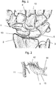
Fig. 1 shows the position of thescaphoid 1 in ahuman wrist 10.Fig. 1 shows thus the bones of a left hand in a dorsal view. Thescaphoid 1 is the most important carpal bone connecting theradius 2 and theulna 3 with thecapitate 4 and the lunate 5. -
Fig. 2 shows a detail of the blood supply to thescaphoid 1 as depicted inFig. 1 . The sectional view ofFig. 2 shows a portion of amain blood vessel 11 and a branchingblood vessel 12 alimenting thescaphoid 1. Because of the distally based blood supply, healing of fractures is at risk because theproximal pole 13 has no blood supply and therefore only bad healing potential. The scaphoid is connected to the lunate with the scapho-lunate ligament 14. If a fracture of thescaphoid 1 does not heal, a pseudoarthrosis will develop. If untreated, the pseudoarthrosis will lead to destruction of the joint cartilage and an arthrosis develops together with an inflammation or arthritis resulting in pain, loss of range of motion and function. -
Figure 3a shows a pseudoarthrosis of thescaphoid 1 on a left hand in an image, which was obtained by conventional x-ray. The MRI-scan inFig. 3b shows a decreased perfusion of theproximal pole 13. The area of decreased perfusion is shown as a dark colored Scaphoid bone compared to the other brighter carpal bones, e.g. the neighboringcapitate 4 or lunate 5. - The development of the arthrosis follows a defined process and results finally in a collapse of the biomechanical important carpal alignment, which will finally lead to a complete arthrosis of the wrist.
Figure 4a - c show the stages of development of the arthrosis in case ofscaphoid nonunion 1. In the first stage of the so-called "Scaphoid Nonunion Advanced Collapse" (= SNAC) arthrosis is shown inFig. 4a and develops between the styloid of theradius 2 and thescaphoid 1 bone. The second stage, as shown inFig. 4b , additionally affects the midcarpal joint betweencapitate 4 and thescaphoid 1 where arthrosis develops. During the third stage, as shown inFig. 4c , the midcarpal joint between scaphoid and lunate 5 bone is also affected. Surgical treatment of the scaphoid pseudoarthrosis according to the prior art consists of a resection of the pseudoarthrosis and reconstruction of the scaphoid using a non-vascularized bone graft (i.e. from the iliac crest). -
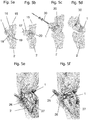
Fig. 5a shows the normal positioned scaphoid.Angle 16 is the scapho-lunate angle (S-L angle) which is calculated between anorthogonal line 15 through the lunate and a line, which lies exactly in theaxis 18 of thescaphoid 1. Normal values range from 30 to 70 degrees. -
Fig. 5b shows a scaphoid in a mal-united position. The scaphoid has like a "humpback" why this mal-united position is called a humpback-deformity.Angle 17 has a value greater than 70 degrees. A correct placedbone graft 20 leads to the results seen inFig. 5c where thescaphoid 1 is in anatomical position and the S-L-angle 16 is normal. Thisbone graft 20 is then fixed using acompression screw 30 seen inFig. 5d . In cases of a vascularity of the proximal pole, a local vascularizedbone graft 25 is used (fig. 5e, fig. 5f orfig. 5g ).Fig. 5e shows the dorsal portion of thedistal radius 2 containing ablood supply 26 after removal of the tissue layers 27 as suggested by Zaidemberg [5]. The treatment of pseudoarthrosis of thescaphoid 1 involves the integration of a local vascularizedbone graft 20 from the dorsal side of thedistal radius 2 into the patient'sscaphoid 1.Fig. 5g shows a variant of a local vascularizedbone graft 35 from the palmar side of thedistal radius 2 as suggested by Kuhlmann/Mathoulin [6]. - Alternatively a free vascularized
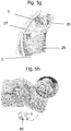
bone graft 40 can be used taken from another location in the body, such as e.g. from the medial femoral condyle as shown inFig. 5h as suggested by Burger [7].Fig. 5h also shows a model of thescaphoid 1 from which the avascular proximal segment has been removed by resection. The resected segment from the knee is attached to thescaphoid 1 shown in the model depicted on the left side of the resectedscaphoid 1. A possible origin of the free vascularizedbone graft 40 is shown by the curved arrow pointing to the location on the medial femoral condyle from which the osteo-cartilaginous graft is harvested to recreate the scaphoid proximal pole. - If these techniques do not lead to healing of the scaphoid bone, a partial fusion would be the next step as shown in
Fig. 6a and 6b . For this reason, the complete scaphoid is excised and a fusion of thecapitate 4, hamate 6, lunate 5 and triquetrum 7 is performed, commonly referred to as a 4-corner fusion. Thefusion element 45 connects inFig. 6b thecapitate 4, lunate 5, triquetrum 7 and hamate 6.Fig. 6c shows a partially fused wrist treated by 4-corner fusion in an x-ray scan. - If the capitate head and the lunate fossa of the distal radius is still in good condition and covered by cartilage, a proximal row carpectomy (PRC) can be performed alternatively as shown in
Fig. 7 . This procedure is only duringSNAC stage 1 andearly stage 2 possible whereas a 4-corner fusion is also possible instage 3. The surgical salvage procedure in the final stage of arthrosis, (complete radio- and midcarpal arthrosis) is the complete fusion of the wrist. -
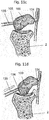
Fig. 8a shows a first view of a scaphoid prosthesis according to a first embodiment of the invention.Fig. 8b shows a second view of the scaphoid prosthesis according toFig. 8a . Thescaphoid prosthesis 100 comprises abody 102 bounded by an outer surface, whereby the outer surface is substantially corresponding to a patient'sscaphoid 1. Thebody 102 of the scaphoid prosthesis comprises atubular base element 105 including afirst end portion 104 and asecond end portion 106 and a plurality of protruding portions. By way of example, a protrudingportion 107 and a protrudingportion 108 are shown inFig. 8a . Apassage 110 is provided in the tubular base element for a fixation means for fixing the scaphoid prosthesis in its position. - The
passage 110 is inFig. 8a and also inFig. 8b only partially visible, therefore, it is shown in dotted lines. Theend portion 104 is configured as an opening of thepassage 110 and is approximated by an ellipsoidal circumference. The shape of the circumference of theend portion 104 can deviate from the ellipsoidal structure depending on the patient's scaphoid forming the basis for the 3D model used for generating the scaphoid prosthesis. - In
Fig. 8b it is also shown, that the shape of theend portion 106 may be approximated by an ellipsoidal circumference. The position of theprotrusions Fig. 8a and of theprotrusions Fig. 8b can be described in relation to the position of thepassage 110 and theend portions - The tubular base element has a longitudinal axis substantially corresponding to the
passage 110 in the body of thescaphoid prosthesis 100. The longitudinal axis substantially extends from thefirst end portion 104 to thesecond end portion 106. The protrudingportions - The scaphoid model is generated from patient data and corresponds in its shape substantially with the patient's scaphoid, thereby the scaphoid prosthesis is obtained from the scaphoid model. The scaphoid model can be designed by a computer aided design software using the anonymized patient data for calculating a shape of a replacement scaphoid of the shape of the patient's scaphoid. The shape of the replacement scaphoid can have an outer surface forming the surface of the scaphoid prosthesis, which has substantially the same shape as the surface of the patient's scaphoid. In particular, the scaphoid prosthesis can be made from a biocompatible material. The scaphoid prosthesis can be made from one of titanium, a plastic or a ceramic material. The plastic can be a biocompatible plastic. The biocompatible plastic can be made of a polymer.
- By way of an example, the manufacture of a scaphoid prosthesis will be explained in the subsequent paragraph. An average size of the prosthesis was evaluated by measuring 9 scaphoids of anonymized computed tomography patient data by making use of the Geomagic Freeform® application resulting in the scaphoid prosthesis according to
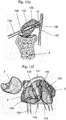
figures 8a /b. The scaphoid prosthesis models obtained by the Geomagic Freeform® application were segmented by making use of the Mimics® 16.0 application. The prototype was then printed in titanium. The surface finishing was performed using vibratory grinding. - According to an alternative embodiment shown in
Fig. 8c , the scaphoid prosthesis is obtained from a tubular or multi-angular shape. The basis for the scaphoid prosthesis according to this embodiment can be a tubular element. This element is provided with a plurality of slits, such that a configuration is obtained, in which a plurality of striped or ribbon-shaped elements are generated. By moving thefirst end portion 104 towards thesecond end portion 106, a bulged structure is formed as the striped or ribbon-shaped elements are bent outwardly. By twisting the first bulged portion with respect the second bulged portion about the longitudinal axis, the bulged structure can be modified to correspond to the structure of a patient's scaphoid. Thus, a plurality ofprotrusions - A
passage 110 can be provided in the scaphoid prosthesis for a fixation means for fixing thescaphoid prosthesis 100 in its position. Thepassage 110 extends from thefirst end portion 104 to thesecond end portion 106. -
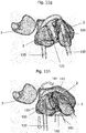
Fig. 9a, 9b, 9c show the integration of thescaphoid prosthesis 100 in the carpal bone and ligament structure. The biomechanical and functional suspension of the prosthesis derives from known procedures forscapholunate ligament 120 reconstruction, which is the ligament between thescaphoid 1 and the lunate 5 bone and one of the main stabilizers of the carpus. Other ligaments for the stabilization of the carpal bone are so called secondary stabilizers and are ligaments between the scaphoid and the carpus other than the scapholunate ligament.Fig. 9a shows the position of ascaphoid prosthesis 100 according to a configuration as described for instance in any of the preceding embodiments. Thescaphoid prosthesis 100 is placed into the space of the patient's scaphoid and precisely fits into the space bounded by theradius 2, the lunate 5 and the other carpal bones. The scaphoid prosthesis is disposed with a passing 110 comprising afirst end portion 104 and asecond end portion 106. Thefirst end portion 104 is shown infig. 9b , as it is not visible infig. 9a . Atendon strip 125 is threaded through thepassage 110 and connected to itself after being passed through a dorsal radio-carpal ligament 115 as shown inFig. 9d in more detail. - Alternatively, the
tendon strip 125 can only be fixed to the lunate 5 or to the lunate 5 and the triquetrum 7 without being passed through a dorsal radio-carpal ligament 115. -
Fig. 9e shows a section of thescapholunate ligament 120, which is arranged on the lower circumference of thescaphoid 1 or thescaphoid prosthesis 100. The scapholunate ligament comprises adorsal portion 121, aproximal portion 122 and apalmar portion 123. - The suspension is carried out through the
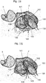
passage 110 in the prosthesis using a tendon strip of the Flexor Carpi Radialis tendon (FCR) 125. A well-known technique described by Marc Garcia-Elias [8] is shown inFig. 9d who modified several techniques for the scapholunate ligament reconstruction. - Alternatively, a minimal invasive and modified technique is described by Mark Henry or arthroscopically assisted by Fernando Corella and shown also in
Fig. 10 . According to this variant, thescaphoid prosthesis 100 is fixed to the lunate by directing a tendon strip of aFCR 135 around thelunate 5. Thepassage 110 in thescaphoid prosthesis 100 extends from the palmar surface of the scaphoid prosthesis to the dorsal surface of thescaphoid prosthesis 100. The palmar surface is located in Fig. 9f on the rear side of the drawing, the dorsal surface is visible and therefore the opening corresponding to thefirst end portion 104. The second opening of thesecond end portion 106 is located on the palmar side. The scaphoid prosthesis is shown in a transparent mode to make thepassage 110 visible, which connects thefirst end portion 104 to thesecond end portion 106. -
Fig. 11a-j show an alternative technique to place and fix ascaphoid prosthesis 100 to lunate 5.Fig. 11a is a top view onto thescaphoid 1 in its biomechanically correct position with respect to the lunate 5 and theradius 2 shown behind the scaphoid and theulna 3. Thescapholunate ligament 120 connecting the scaphoid and the lunate is shown in their normal position.Fig. 11b shows a rupture of the scapholunate ligament.Fig. 11c shows the first step of a scapholunate ligament reconstruction from a lateral view as proposed by Fernando Corella, with the principal modification that the patient'sscaphoid 1 is substituted by thescaphoid prosthesis 100 according to any of the preceding embodiments. The scaphoid prosthesis is disposed with apassage 110. Atendon strip 135 is threaded through thepassage 110 from thefirst end portion 104 to thesecond end portion 106. Thetendon strip 135 can be a portion of the FCR (flexor carpi radialis) tendon or another one. InFig. 11d it is shown, that thescaphoid prosthesis 100 is placed in the biomechanically correct position by pulling the end of thetendon strip 135 extending from thesecond end portion 106. Thereby the scaphoid prosthesis is rotated and/or repositioned on the joint socket of theradius 2. -
Fig. 11e shows a section of thescaphoid prosthesis 100 showing thepassage 110. Thetendon strip 135 extends through thepassage 110. A portion of thetendon strip 135 is shown in section, which reveals theinner structure 136 of thetendon strip 135. The inner structure includes aninterference screw 137, as an example of a fixation element, which is used for fixing thetendon strip 135 in its position in thepassage 110. Thepassage 110 is at least on the location of the desired final position of the interference screw 138 is disposed with a thread corresponding to the thread of theinterference screw 137. The diameter of thepassage 110 may be greater than the outer diameter of theinterference screw 137 in those locations, which the interference screw has to pass before reaching its final position. - Alternatively, the passage may be composed of a first hole and a second hole, whereby the first hole comprises a longitudinal axis and the second hole comprises a longitudinal axis. The first and second longitudinal axes extend in a substantially parallel configuration to each other. The first hole and the second hole advantageously include a common intersection plane, such that a portion of the first hole extends into the second hole and a portion of the second hole extends into the first hole. One of the first or second holes is advantageously disposed with a thread. According to an embodiment, the surface of the passage can include a roughened portion. The roughened portion may form an anchoring portion for an interference screw. A thread may be formed in the roughened portion by the interference screw when placing the interference screw in the roughened portion. The roughened portion advantageously comprises a material which softer or at most of the same hardness as the material of the interference screw. A softer material may ease the positioning of the interference screw in the roughened portion of the
passage 110. -
Fig. 11f shows the fixation of thetendon strip 135 onto thelunate bone 5 on the palmar side. Thelunate bone 5 is disposed with apassage 150, which receives another portion of thetendon strip 135. Thereby thescaphoid prosthesis 100 can be connected to thelunate bone 5.Fig. 11f further shows afixation element 140, which connects thescaphoid prosthesis 100 to the lunate 5 on the palmar side. Thefixation element 140 is also tied to the first andsecond end scapholunate ligament 120 on its dorsal side by athread 143 and to the FCR (or other tendon) tendon, such that in particular thetendon strip 135 taken from the FCR is united by a suture to the main body of the FCR tendon. Thereby thescapholunate ligament 120 can be reconstructed and the position of thescaphoid prosthesis 100 can be stabilized. -
Fig. 11g shows a section of thetendon strip 135 in thescaphoid prosthesis 100. -
Fig. 11h shows an adjustment of the position of thescaphoid prosthesis 100 with respect to the lunate 5 by pulling thetendon strip 135. Thefirst end 141 and thesecond end 142 of the rupturedscapholunate ligament 120 are moved closer to each other. In a next step shown inFig. 11i , the end of thetendon strip 135 is attached to thefixation element 140 by passing the two ends of thethread 143 through the end of thetendon strip 135. -
Fig. 11j shows that the two ends of thethread 143 are tied together to aknot 144. Thereby thetendon strip 135 is fixed in its position and the scaphoid prosthesis as well as the two ends 141, 142 of thescapholunate ligament 120 are fixed in their respective positions. - An aspect of the disclosure relates to a method for manufacturing a scaphoid prosthesis comprising a body bounded by an outer surface, wherein the outer surface is substantially corresponding to a patient's scaphoid, wherein the body of the scaphoid prosthesis comprises a tubular base element including a first end portion and a second end portion and a plurality of protruding portions wherein a single passage is provided in the tubular base element configured to engage a fixation means for fixing the scaphoid prosthesis in its position, wherein the passage is configured as a curved passage, the method comprising an additive manufacturing step.
- In one embodiment, the method comprising, by a
computing device 200 such as shown inFig. 12 , receiving data relating to the shape of a patient's scaphoid and generating a scaphoid model, wherein the shape of the scaphoid model corresponds to the shape of the patient's scaphoid. - In one embodiment, the method comprising, by a
computing device 200, generating a scaphoid model utilizing data relating to the shape of a patient's scaphoid. - A method for manufacturing a scaphoid prosthesis according to any of the preceding embodiments comprises an additive manufacturing step. In a first step of the method data are obtained relating to the shape of a patient's scaphoid, in a second step a scaphoid model can be generated by a computer aided design software. The scaphoid model can be generated from patient data. Advantageously, the scaphoid model can correspond in its shape substantially with the patient's scaphoid. In a third step of the method, the scaphoid prosthesis can be obtained from the scaphoid model by the additive manufacturing method.
- A method for manufacturing a scaphoid prosthesis according to any of the preceding embodiments, wherein the scaphoid prosthesis is formed from a tubular element comprising a plurality of ribbon-shaped elements, whereby the outer shape of the scaphoid prosthesis is shaped by moving the first end portion towards the second end portion such that a roughly spherical or ellipsoidal shape is obtained, whereby the first end portion is twisted relative to the second end portion such that a scaphoid shape is obtained which corresponds roughly to the surface of the patient's scaphoid.
- The
computing device 200 as shown inFig. 12 , can have aprocessor 202 configured to generate a scaphoid model. Theprocessor 202 can be used to run operating system applications, firmware applications, media playback applications, media editing applications, or any other application. In some embodiments,processor 202 can drive a display and process inputs received from an interface. Theprocessor 202 can be an FPGA, ASIC, microchip, hardwired circuit, software controlled processor, DSP, or the like. - The
computing device 200 can havestorage 204, such as, one or more storage mediums including a hard-drive, solid state drive, flash memory, permanent memory such as ROM, any other suitable type of storage component, or any combination thereof.Storage 204 can store, for example, media data (e.g., audio or video files), application data (e.g., for implementing functions on the computing device 200), firmware, data relating to the shape of a patient's scaphoid and/or scaphoid model, and any other suitable data or any combination thereof. - The
computing device 200 can have amemory 206, such as a cache memory, a semi-permanent memory, such as a RAM, and/or one or more different types of memory used for temporarily storing data. In some embodiments, thememory 206 can also be used for storing data used to operate computing device applications, or any other type of data that can be stored in thestorage 204. In some embodiments, thememory 206 and thestorage 204 can be combined as a single storage medium. In some embodiments, thememory 206 and thestorage 204 are coupled to theprocessor 202. - The
computing device 200 can have auser interface 208 configured to receive instructions, e.g. from a user, by way of a keyboard, keypad, touch pad, microphone, movement sensor, gesture sensor, camera, or the like. Theuser interface 208 can have a display/monitor of any type (LED, LCD, OLED, Plasma, CRT, or the like) and/or sound generators, such as speakers. - The
computing device 200 can havecommunications circuitry 210, for example, anysuitable communications circuitry 210 configured to connect to a communications network and to transmit communications (e.g., voice or data) fromcomputing device 200 to other electronic devices. Thecommunication circuitry 210 can have receivers and/or transmitters. The receivers can be configured to receive instructions from a device and thus allows a user to enter instructions into thecomputing device 200. The transmitters can be configured to transmit instructions from thecomputing device 200 and thus allow a user to send instructions from thecomputing device 200 to another device, such as a device used in an additive manufacturing method. The receivers and/or transmitters, and thecomputing device 200 corresponding thereto, can be configured to communicate over a wired connection or over a wireless connection, such as via Ethernet, LAN, WAN, Bluetooth, WiFi, IR communication, or a cloud environment. It should be apparent to those skilled in the art that many more modifications besides those already described are possible without departing from the inventive concepts herein. The inventive subject matter, therefore, is not to be restricted except in the scope of the appended claims. Moreover, in interpreting both the specification and the claims, all terms should be interpreted in the broadest possible manner consistent with the context. In particular, the terms "comprises" and "comprising" should be interpreted as referring to elements, components, or steps in a non-exclusive manner, indicating that the referenced elements, components, or steps may be present, or utilized, or combined with other elements, components, or steps that are not expressly referenced. Where the specification claims refers to at least one of an element or compound selected from the group consisting of A, B, C .... and N, the text should be interpreted as requiring only one element from the group, not A plus N, or B plus N, etc. -
- 1. AGNER O (1963) TREATMENT OF NON-UNITED NAVICULAR FRACTURES BY TOTAL EXCISION OF THE BONE AND THE INSERTION OF ACRYLIC PROSTHESES. Acta Orthop Scand 33:235-245.
- 2. Spingardi O, Rossello MI (2011) The total scaphoid titanium arthroplasty: A 15-year experience. Hand (N Y) 6:179-184. doi: 10.1007/s11552-010-9315-3
- 3. Henry M (2013) Reconstruction of Both Volar and Dorsal Limbs of the Scapholunate Interosseous Ligament. YJHSU 38:1625-1634. doi: 10.1016/j.jhsa.2013.05.026
- 4. Corella Fernando (2013), Del Cerro MD M, MD MO, PhD RL-G (2013) Arthroscopic Ligamentoplasty of the Dorsal and Volar Portions of the Scapholunate Ligament. YJHSU 38:2466-2477. doi: 10.1016/j.jhsa.2013.09.021
- 5. Zaidemberg C, Siebert JW, Angrigiani C (1991) A new vascularized bone graft for scaphoid nonunion. YJHSU 16:474-478.
- 6. Mathoulin C, Haerle M (1998) Vascularized bone graft from the palmar carpal artery for treatment of scaphoid nonunion. J Hand Surg Br 23:318-323.
- 7. Burger HK, Windhofer C, Gaggl AJ, Higgins JP (2013) Vascularized Medial Femoral Trochlea Osteocartilaginous Flap Reconstruction of Proximal Pole Scaphoid Nonunions. YJHSU 38:690-700. doi: 10.1016/j.jhsa.2013.01.036
- 8. Garcia-Elias M, Lluch AL, Stanley JK (2006) Three-ligament tenodesis for the treatment of scapholunate dissociation: indications and surgical technique. YJHSU 31:125-134. doi: 10.1016/j.jhsa.2005.10.011
Claims (15)
- A scaphoid prosthesis (100) comprising a body (102) bounded by an outer surface (101), wherein the outer surface (101) is substantially corresponding to a patient's scaphoid (1), wherein the body (102) of the scaphoid prosthesis comprises a tubular base element (105) including a first end portion (104) and a second end portion (106) and a plurality of protruding portions (107, 108, 109) wherein a single passage (110) is provided in the tubular base element (105) configured to engage a fixation means for fixing the scaphoid prosthesis (100) in its position, characterized in that the passage is configured as a curved passage.
- The scaphoid prosthesis (100) of claim 1, wherein the passage (110) is positioned in the body (102) in such a way that the distance between a passage wall and the body surface measured along any line intersecting with a longitudinal axis is substantially uniform in any cross-sectional area arranged normally to the longitudinal axis of the passage (110).
- The scaphoid prosthesis (100) of claim 2, wherein the passage (110) extends from the first end portion (104) to the second end portion (106).
- The scaphoid prosthesis (100) according to any one of the preceding claims, wherein the passage (110) comprises an attachment portion.
- The scaphoid prosthesis (100) according to any one of the preceding claims, wherein the passage (110) comprises first hole and a second hole, wherein the first hole comprises a first longitudinal axis and the second hole comprises a second longitudinal axis, wherein the first and second longitudinal axes are arranged in an angle to each other.
- The scaphoid prosthesis (100) according to any one of the preceding claims, the body comprising a contralateral side, wherein the body (102) is anatomically contoured based on data of the contralateral side or from a database.
- The scaphoid prosthesis (100) according to any one of the preceding claims, wherein the protruding portions (107, 108, 109) have a substantially spherical or ellipsoid shape twisted about a longitudinal axis, wherein the twisting angle of the first end portion (104) relative to the second end portion (106) is about 90 degrees.
- The scaphoid prosthesis (100) according to any one of the preceding claims, whereby the scaphoid prosthesis is created utilizing a scaphoid model, wherein the scaphoid model is generated utilizing patient scaphoid data and wherein the shape of the scaphoid model represents the shape of the scaphoid prosthesis.
- The scaphoid prosthesis (100) according to any one of the preceding claims, wherein the scaphoid prosthesis is made from a biocompatible material.
- The scaphoid prosthesis (100) per any one of the preceding claims, wherein the scaphoid prosthesis is made from a material which comprises at least one element from the group consisting of titanium, a biocompatible plastic, and a ceramic material, wherein the biocompatible plastic comprises in particular a polymer, for instance a polyetheretherketone, or the ceramic material comprises for instance a ceramic material containing zirconia.
- The scaphoid prosthesis (100) according to any one of the preceding claims, wherein the scaphoid prosthesis comprises an attachment portion configured to engage a fixation element, wherein the fixation element is configured to fix the scaphoid prosthesis in its position, wherein the fixation element can be configured as a tendon strip (135).
- The scaphoid prosthesis (100) according to any one of the preceding claims, wherein the scaphoid prosthesis is obtained by an additive manufacturing method.
- A method for manufacturing a scaphoid prosthesis (100) according to any one of the preceding claims, the method comprising an additive manufacturing step.
- The method according to claim 13, wherein in a first step, data are obtained relating to the shape of a patient's scaphoid (1), in a second step a scaphoid model is generated by a computer aided design software, wherein the scaphoid model which is generated from patient data and corresponds in its shape substantially with the patient's scaphoid, whereby the scaphoid prosthesis (100) is obtained from the scaphoid model in a third step by the additive manufacturing method.
- The method according to one of claims 13 or 14, wherein the scaphoid model is designed by a computer aided design software using the patient data for calculating a shape of a replacement scaphoid of the shape of the patient's scaphoid.
Priority Applications (4)
| Application Number | Priority Date | Filing Date | Title |
|---|---|---|---|
| US15/349,830 US20170143501A1 (en) | 2015-11-22 | 2016-11-11 | Scaphoid Prosthesis |
| EP16198305.1A EP3170477B1 (en) | 2015-11-22 | 2016-11-11 | Scaphoid prosthesis |
| PCT/EP2017/060864 WO2018086765A1 (en) | 2015-11-22 | 2017-05-08 | Scaphoid prosthesis |
| AU2017357400A AU2017357400B2 (en) | 2016-11-11 | 2017-05-08 | Scaphoid prosthesis |
Applications Claiming Priority (2)
| Application Number | Priority Date | Filing Date | Title |
|---|---|---|---|
| EP15195745 | 2015-11-22 | ||
| EP16198305.1A EP3170477B1 (en) | 2015-11-22 | 2016-11-11 | Scaphoid prosthesis |
Publications (2)
| Publication Number | Publication Date |
|---|---|
| EP3170477A1 true EP3170477A1 (en) | 2017-05-24 |
| EP3170477B1 EP3170477B1 (en) | 2020-02-19 |
Family
ID=64662794
Family Applications (1)
| Application Number | Title | Priority Date | Filing Date |
|---|---|---|---|
| EP16198305.1A Active EP3170477B1 (en) | 2015-11-22 | 2016-11-11 | Scaphoid prosthesis |
Country Status (3)
| Country | Link |
|---|---|
| US (1) | US20170143501A1 (en) |
| EP (1) | EP3170477B1 (en) |
| WO (1) | WO2018086765A1 (en) |
Families Citing this family (3)
| Publication number | Priority date | Publication date | Assignee | Title |
|---|---|---|---|---|
| US10925746B2 (en) * | 2018-07-25 | 2021-02-23 | Orthopedix, Inc. | Patient specific carpal implant |
| DE102019114314A1 (en) * | 2019-05-28 | 2020-12-03 | Rheinisch-Westfälische Technische Hochschule Aachen (RWTH) | Wrist endoprosthesis |
| CN112137767B (en) * | 2020-09-18 | 2024-04-12 | 湖南华翔医疗科技有限公司 | Integrated replacement navicular bone used in orthopedic operation and matched machining and installing method |
Citations (8)
| Publication number | Priority date | Publication date | Assignee | Title |
|---|---|---|---|---|
| US4158893A (en) | 1976-10-12 | 1979-06-26 | Swanson Alfred B | Protective sleeve for implantable prosthesis and method of protecting the prosthesis |
| US4164793A (en) | 1978-04-26 | 1979-08-21 | Swanson Alfred B | Lunate implant |
| US4645505A (en) | 1985-03-07 | 1987-02-24 | Swanson Alfred B | Wrist implant |
| US5702468A (en) | 1995-03-09 | 1997-12-30 | Uresil Corporation | Carpal bone biaxially restrained prosthesis |
| US6371985B1 (en) | 1995-03-09 | 2002-04-16 | Robert S. Goldberg | Prostheses restrained by immediate attachment while ingrowth proceeds naturally over time |
| US20050033426A1 (en) | 2003-01-07 | 2005-02-10 | Ogilvie William F. | Carpometacarpal joint prosthesis |
| WO2008001185A2 (en) | 2006-06-29 | 2008-01-03 | Bioprofile | Assembly between a part made of pyrolytic carbon and another part |
| WO2009076758A1 (en) | 2007-12-18 | 2009-06-25 | The Royal Institution For The Advancement Of Learning/Mcgill University | Orthopaedic implants |
Family Cites Families (2)
| Publication number | Priority date | Publication date | Assignee | Title |
|---|---|---|---|---|
| US4198712A (en) * | 1978-10-13 | 1980-04-22 | Swanson Alfred B | Scaphoid implant |
| US4936860A (en) * | 1988-09-23 | 1990-06-26 | Swanson Alfred B | Metal scaphoid implant |
-
2016
- 2016-11-11 US US15/349,830 patent/US20170143501A1/en not_active Abandoned
- 2016-11-11 EP EP16198305.1A patent/EP3170477B1/en active Active
-
2017
- 2017-05-08 WO PCT/EP2017/060864 patent/WO2018086765A1/en active Application Filing
Patent Citations (8)
| Publication number | Priority date | Publication date | Assignee | Title |
|---|---|---|---|---|
| US4158893A (en) | 1976-10-12 | 1979-06-26 | Swanson Alfred B | Protective sleeve for implantable prosthesis and method of protecting the prosthesis |
| US4164793A (en) | 1978-04-26 | 1979-08-21 | Swanson Alfred B | Lunate implant |
| US4645505A (en) | 1985-03-07 | 1987-02-24 | Swanson Alfred B | Wrist implant |
| US5702468A (en) | 1995-03-09 | 1997-12-30 | Uresil Corporation | Carpal bone biaxially restrained prosthesis |
| US6371985B1 (en) | 1995-03-09 | 2002-04-16 | Robert S. Goldberg | Prostheses restrained by immediate attachment while ingrowth proceeds naturally over time |
| US20050033426A1 (en) | 2003-01-07 | 2005-02-10 | Ogilvie William F. | Carpometacarpal joint prosthesis |
| WO2008001185A2 (en) | 2006-06-29 | 2008-01-03 | Bioprofile | Assembly between a part made of pyrolytic carbon and another part |
| WO2009076758A1 (en) | 2007-12-18 | 2009-06-25 | The Royal Institution For The Advancement Of Learning/Mcgill University | Orthopaedic implants |
Non-Patent Citations (10)
| Title |
|---|
| AGNER 0: "TREATMENT OF NON-UNITED NAVICULAR FRACTURES BY TOTAL EXCISION OF THE BONE AND THE INSERTION OF ACRYLIC PROSTHESES", ACTA ORTHOP SCAND, vol. 33, 1963, pages 235 - 245 |
| BURGER HK; WINDHOFER C; GAGGL AJ; HIGGINS JP: "Vascularized Medial Femoral Trochlea Osteocartilaginous Flap Reconstruction of Proximal Pole Scaphoid Nonunions", YJHSU, vol. 38, 2013, pages 690 - 700 |
| CORELLA FERNANDO ET AL: "Arthroscopic Ligamentoplasty of the Dorsal and Volar Portions of the Scapholunate Ligament", THE JOURNAL OF HAND SURGERY, vol. 38, no. 12, 31 December 2013 (2013-12-31), pages 2466 - 2477, XP028783326, ISSN: 0363-5023, DOI: 10.1016/J.JHSA.2013.09.021 * |
| CORELLA FERNANDO: "Del Cerro MD M, MD MO, PhD RL-G (2013) Arthroscopic Ligamentoplasty of the Dorsal and Volar Portions of the Scapholunate Ligament", YJHSU, vol. 38, 2013, pages 2466 - 2477 |
| GARCIA-ELIAS ET AL: "Three-Ligament Tenodesis for the Treatment of Scapholunate Dissociation: Indications and Surgical Technique", THE JOURNAL OF HAND SURGERY, W.B. SAUNDERS, AMSTERDAM, NL, vol. 31, no. 1, 1 January 2006 (2006-01-01), pages 125 - 134, XP005266142, ISSN: 0363-5023, DOI: 10.1016/J.JHSA.2005.10.011 * |
| GARCIA-ELIAS M; LLUCH AL; STANLEY JK: "Three-ligament tenodesis for the treatment of scapholunate dissociation: indications and surgical technique", YJHSU, vol. 31, 2006, pages 125 - 134 |
| HENRY M: "Reconstruction of Both Volar and Dorsal Limbs of the Scapholunate Interosseous Ligament", YJHSU, vol. 38, 2013, pages 1625 - 1634 |
| MATHOULIN C; HAERLE M: "Vascularized bone graft from the palmar carpal artery for treatment of scaphoid nonunion", J HAND SURG BR, vol. 23, 1998, pages 318 - 323 |
| SPINGARDI 0; ROSSELLO MI: "The total scaphoid titanium arthroplasty: A 15-year experience", HAND (N Y, vol. 6, 2011, pages 179 - 184 |
| ZAIDEMBERG C; SIEBERT JW; ANGRIGIANI C: "A new vascularized bone graft for scaphoid nonunion", YJHSU, vol. 16, 1991, pages 474 - 478 |
Also Published As
| Publication number | Publication date |
|---|---|
| EP3170477B1 (en) | 2020-02-19 |
| US20170143501A1 (en) | 2017-05-25 |
| WO2018086765A1 (en) | 2018-05-17 |
Similar Documents
| Publication | Publication Date | Title |
|---|---|---|
| US10828169B2 (en) | Stemless shoulder implant | |
| JP5198069B2 (en) | Patient-selectable knee arthroplasty device | |
| JP4507097B2 (en) | Implant three-dimensional surgical planning system based on optimal balance between morphological and functional evaluation | |
| EP3049003B1 (en) | Prosthetic augments to improve muscle mechanics | |
| JP2006501977A (en) | Minimally invasive joint implant with a three-dimensional profile that conforms to the joint surface | |
| Prkić et al. | Total elbow arthroplasty is moving forward: review on past, present and future | |
| EP3170477B1 (en) | Scaphoid prosthesis | |
| AU2016305486A1 (en) | A joint prosthesis | |
| US11890197B2 (en) | Cruciate replacing artificial knee | |
| US10918488B2 (en) | Intercarpal surgical implant | |
| AU2017357400B2 (en) | Scaphoid prosthesis | |
| JP6659683B2 (en) | Humeral tray with well-designed nodule augmentation to improve joint mechanisms | |
| EP3463198A1 (en) | Implant, fitting plate and method of manufacturing an implant and fitting plate | |
| ES2784929T3 (en) | Scaphoid prosthesis | |
| US20140128984A1 (en) | Artificial implant for carpometacarpal joint | |
| Barnes et al. | Micromotion and push‐out evaluation of an additive manufactured implant for above‐the‐knee amputees | |
| Spinelli et al. | Femoral stem-bone interface analysis of logical uncemented stem | |
| Abouel Nasr et al. | Developing a methodology for analysis and manufacturing of proximal interphalangeal (PIP) joint using rapid prototyping technique | |
| CN113069248A (en) | Bone defect repair system for wrist joint | |
| CN111938878A (en) | Tibia prosthesis | |
| RU2651104C1 (en) | Method of modeling and personified skeletal bone endoprosthesis appliance | |
| US20230263637A1 (en) | Joint implant apparatus, system, and method | |
| CN219803844U (en) | 3D prints half joint bionic rib prosthesis | |
| CN113974918B (en) | Nodule reduction assembly for half-shoulder replacement prosthesis and preparation method thereof | |
| US20220192837A1 (en) | Device for acromion replacement |
Legal Events
| Date | Code | Title | Description |
|---|---|---|---|
| PUAI | Public reference made under article 153(3) epc to a published international application that has entered the european phase |
Free format text: ORIGINAL CODE: 0009012 |
|
| STAA | Information on the status of an ep patent application or granted ep patent |
Free format text: STATUS: THE APPLICATION HAS BEEN PUBLISHED |
|
| AK | Designated contracting states |
Kind code of ref document: A1 Designated state(s): AL AT BE BG CH CY CZ DE DK EE ES FI FR GB GR HR HU IE IS IT LI LT LU LV MC MK MT NL NO PL PT RO RS SE SI SK SM TR |
|
| AX | Request for extension of the european patent |
Extension state: BA ME |
|
| STAA | Information on the status of an ep patent application or granted ep patent |
Free format text: STATUS: REQUEST FOR EXAMINATION WAS MADE |
|
| 17P | Request for examination filed |
Effective date: 20171124 |
|
| RBV | Designated contracting states (corrected) |
Designated state(s): AL AT BE BG CH CY CZ DE DK EE ES FI FR GB GR HR HU IE IS IT LI LT LU LV MC MK MT NL NO PL PT RO RS SE SI SK SM TR |
|
| STAA | Information on the status of an ep patent application or granted ep patent |
Free format text: STATUS: EXAMINATION IS IN PROGRESS |
|
| 17Q | First examination report despatched |
Effective date: 20181206 |
|
| RAP1 | Party data changed (applicant data changed or rights of an application transferred) |
Owner name: MEDARTIS HOLDING AG |
|
| GRAP | Despatch of communication of intention to grant a patent |
Free format text: ORIGINAL CODE: EPIDOSNIGR1 |
|
| STAA | Information on the status of an ep patent application or granted ep patent |
Free format text: STATUS: GRANT OF PATENT IS INTENDED |
|
| INTG | Intention to grant announced |
Effective date: 20190605 |
|
| GRAS | Grant fee paid |
Free format text: ORIGINAL CODE: EPIDOSNIGR3 |
|
| GRAJ | Information related to disapproval of communication of intention to grant by the applicant or resumption of examination proceedings by the epo deleted |
Free format text: ORIGINAL CODE: EPIDOSDIGR1 |
|
| GRAL | Information related to payment of fee for publishing/printing deleted |
Free format text: ORIGINAL CODE: EPIDOSDIGR3 |
|
| STAA | Information on the status of an ep patent application or granted ep patent |
Free format text: STATUS: EXAMINATION IS IN PROGRESS |
|
| GRAR | Information related to intention to grant a patent recorded |
Free format text: ORIGINAL CODE: EPIDOSNIGR71 |
|
| STAA | Information on the status of an ep patent application or granted ep patent |
Free format text: STATUS: GRANT OF PATENT IS INTENDED |
|
| INTC | Intention to grant announced (deleted) | ||
| INTG | Intention to grant announced |
Effective date: 20191009 |
|
| GRAA | (expected) grant |
Free format text: ORIGINAL CODE: 0009210 |
|
| STAA | Information on the status of an ep patent application or granted ep patent |
Free format text: STATUS: THE PATENT HAS BEEN GRANTED |
|
| AK | Designated contracting states |
Kind code of ref document: B1 Designated state(s): AL AT BE BG CH CY CZ DE DK EE ES FI FR GB GR HR HU IE IS IT LI LT LU LV MC MK MT NL NO PL PT RO RS SE SI SK SM TR |
|
| REG | Reference to a national code |
Ref country code: CH Ref legal event code: EP |
|
| REG | Reference to a national code |
Ref country code: DE Ref legal event code: R096 Ref document number: 602016029983 Country of ref document: DE |
|
| REG | Reference to a national code |
Ref country code: AT Ref legal event code: REF Ref document number: 1234082 Country of ref document: AT Kind code of ref document: T Effective date: 20200315 |
|
| REG | Reference to a national code |
Ref country code: IE Ref legal event code: FG4D |
|
| REG | Reference to a national code |
Ref country code: NL Ref legal event code: MP Effective date: 20200219 |
|
| PG25 | Lapsed in a contracting state [announced via postgrant information from national office to epo] |
Ref country code: FI Free format text: LAPSE BECAUSE OF FAILURE TO SUBMIT A TRANSLATION OF THE DESCRIPTION OR TO PAY THE FEE WITHIN THE PRESCRIBED TIME-LIMIT Effective date: 20200219 Ref country code: RS Free format text: LAPSE BECAUSE OF FAILURE TO SUBMIT A TRANSLATION OF THE DESCRIPTION OR TO PAY THE FEE WITHIN THE PRESCRIBED TIME-LIMIT Effective date: 20200219 Ref country code: NO Free format text: LAPSE BECAUSE OF FAILURE TO SUBMIT A TRANSLATION OF THE DESCRIPTION OR TO PAY THE FEE WITHIN THE PRESCRIBED TIME-LIMIT Effective date: 20200519 |
|
| REG | Reference to a national code |
Ref country code: LT Ref legal event code: MG4D |
|
| PG25 | Lapsed in a contracting state [announced via postgrant information from national office to epo] |
Ref country code: IS Free format text: LAPSE BECAUSE OF FAILURE TO SUBMIT A TRANSLATION OF THE DESCRIPTION OR TO PAY THE FEE WITHIN THE PRESCRIBED TIME-LIMIT Effective date: 20200619 Ref country code: GR Free format text: LAPSE BECAUSE OF FAILURE TO SUBMIT A TRANSLATION OF THE DESCRIPTION OR TO PAY THE FEE WITHIN THE PRESCRIBED TIME-LIMIT Effective date: 20200520 Ref country code: BG Free format text: LAPSE BECAUSE OF FAILURE TO SUBMIT A TRANSLATION OF THE DESCRIPTION OR TO PAY THE FEE WITHIN THE PRESCRIBED TIME-LIMIT Effective date: 20200519 Ref country code: HR Free format text: LAPSE BECAUSE OF FAILURE TO SUBMIT A TRANSLATION OF THE DESCRIPTION OR TO PAY THE FEE WITHIN THE PRESCRIBED TIME-LIMIT Effective date: 20200219 Ref country code: LV Free format text: LAPSE BECAUSE OF FAILURE TO SUBMIT A TRANSLATION OF THE DESCRIPTION OR TO PAY THE FEE WITHIN THE PRESCRIBED TIME-LIMIT Effective date: 20200219 Ref country code: SE Free format text: LAPSE BECAUSE OF FAILURE TO SUBMIT A TRANSLATION OF THE DESCRIPTION OR TO PAY THE FEE WITHIN THE PRESCRIBED TIME-LIMIT Effective date: 20200219 |
|
| PG25 | Lapsed in a contracting state [announced via postgrant information from national office to epo] |
Ref country code: NL Free format text: LAPSE BECAUSE OF FAILURE TO SUBMIT A TRANSLATION OF THE DESCRIPTION OR TO PAY THE FEE WITHIN THE PRESCRIBED TIME-LIMIT Effective date: 20200219 |
|
| REG | Reference to a national code |
Ref country code: ES Ref legal event code: FG2A Ref document number: 2784929 Country of ref document: ES Kind code of ref document: T3 Effective date: 20201002 |
|
| PG25 | Lapsed in a contracting state [announced via postgrant information from national office to epo] |
Ref country code: DK Free format text: LAPSE BECAUSE OF FAILURE TO SUBMIT A TRANSLATION OF THE DESCRIPTION OR TO PAY THE FEE WITHIN THE PRESCRIBED TIME-LIMIT Effective date: 20200219 Ref country code: LT Free format text: LAPSE BECAUSE OF FAILURE TO SUBMIT A TRANSLATION OF THE DESCRIPTION OR TO PAY THE FEE WITHIN THE PRESCRIBED TIME-LIMIT Effective date: 20200219 Ref country code: EE Free format text: LAPSE BECAUSE OF FAILURE TO SUBMIT A TRANSLATION OF THE DESCRIPTION OR TO PAY THE FEE WITHIN THE PRESCRIBED TIME-LIMIT Effective date: 20200219 Ref country code: SM Free format text: LAPSE BECAUSE OF FAILURE TO SUBMIT A TRANSLATION OF THE DESCRIPTION OR TO PAY THE FEE WITHIN THE PRESCRIBED TIME-LIMIT Effective date: 20200219 Ref country code: PT Free format text: LAPSE BECAUSE OF FAILURE TO SUBMIT A TRANSLATION OF THE DESCRIPTION OR TO PAY THE FEE WITHIN THE PRESCRIBED TIME-LIMIT Effective date: 20200712 Ref country code: SK Free format text: LAPSE BECAUSE OF FAILURE TO SUBMIT A TRANSLATION OF THE DESCRIPTION OR TO PAY THE FEE WITHIN THE PRESCRIBED TIME-LIMIT Effective date: 20200219 Ref country code: CZ Free format text: LAPSE BECAUSE OF FAILURE TO SUBMIT A TRANSLATION OF THE DESCRIPTION OR TO PAY THE FEE WITHIN THE PRESCRIBED TIME-LIMIT Effective date: 20200219 Ref country code: RO Free format text: LAPSE BECAUSE OF FAILURE TO SUBMIT A TRANSLATION OF THE DESCRIPTION OR TO PAY THE FEE WITHIN THE PRESCRIBED TIME-LIMIT Effective date: 20200219 |
|
| REG | Reference to a national code |
Ref country code: DE Ref legal event code: R097 Ref document number: 602016029983 Country of ref document: DE |
|
| PLBE | No opposition filed within time limit |
Free format text: ORIGINAL CODE: 0009261 |
|
| STAA | Information on the status of an ep patent application or granted ep patent |
Free format text: STATUS: NO OPPOSITION FILED WITHIN TIME LIMIT |
|
| 26N | No opposition filed |
Effective date: 20201120 |
|
| PG25 | Lapsed in a contracting state [announced via postgrant information from national office to epo] |
Ref country code: IT Free format text: LAPSE BECAUSE OF FAILURE TO SUBMIT A TRANSLATION OF THE DESCRIPTION OR TO PAY THE FEE WITHIN THE PRESCRIBED TIME-LIMIT Effective date: 20200219 |
|
| PG25 | Lapsed in a contracting state [announced via postgrant information from national office to epo] |
Ref country code: PL Free format text: LAPSE BECAUSE OF FAILURE TO SUBMIT A TRANSLATION OF THE DESCRIPTION OR TO PAY THE FEE WITHIN THE PRESCRIBED TIME-LIMIT Effective date: 20200219 Ref country code: SI Free format text: LAPSE BECAUSE OF FAILURE TO SUBMIT A TRANSLATION OF THE DESCRIPTION OR TO PAY THE FEE WITHIN THE PRESCRIBED TIME-LIMIT Effective date: 20200219 |
|
| REG | Reference to a national code |
Ref country code: AT Ref legal event code: UEP Ref document number: 1234082 Country of ref document: AT Kind code of ref document: T Effective date: 20200219 |
|
| PG25 | Lapsed in a contracting state [announced via postgrant information from national office to epo] |
Ref country code: MC Free format text: LAPSE BECAUSE OF FAILURE TO SUBMIT A TRANSLATION OF THE DESCRIPTION OR TO PAY THE FEE WITHIN THE PRESCRIBED TIME-LIMIT Effective date: 20200219 |
|
| PG25 | Lapsed in a contracting state [announced via postgrant information from national office to epo] |
Ref country code: LU Free format text: LAPSE BECAUSE OF NON-PAYMENT OF DUE FEES Effective date: 20201111 |
|
| PG25 | Lapsed in a contracting state [announced via postgrant information from national office to epo] |
Ref country code: IE Free format text: LAPSE BECAUSE OF NON-PAYMENT OF DUE FEES Effective date: 20201111 |
|
| PG25 | Lapsed in a contracting state [announced via postgrant information from national office to epo] |
Ref country code: TR Free format text: LAPSE BECAUSE OF FAILURE TO SUBMIT A TRANSLATION OF THE DESCRIPTION OR TO PAY THE FEE WITHIN THE PRESCRIBED TIME-LIMIT Effective date: 20200219 Ref country code: MT Free format text: LAPSE BECAUSE OF FAILURE TO SUBMIT A TRANSLATION OF THE DESCRIPTION OR TO PAY THE FEE WITHIN THE PRESCRIBED TIME-LIMIT Effective date: 20200219 Ref country code: CY Free format text: LAPSE BECAUSE OF FAILURE TO SUBMIT A TRANSLATION OF THE DESCRIPTION OR TO PAY THE FEE WITHIN THE PRESCRIBED TIME-LIMIT Effective date: 20200219 |
|
| PG25 | Lapsed in a contracting state [announced via postgrant information from national office to epo] |
Ref country code: MK Free format text: LAPSE BECAUSE OF FAILURE TO SUBMIT A TRANSLATION OF THE DESCRIPTION OR TO PAY THE FEE WITHIN THE PRESCRIBED TIME-LIMIT Effective date: 20200219 Ref country code: AL Free format text: LAPSE BECAUSE OF FAILURE TO SUBMIT A TRANSLATION OF THE DESCRIPTION OR TO PAY THE FEE WITHIN THE PRESCRIBED TIME-LIMIT Effective date: 20200219 |
|
| PGFP | Annual fee paid to national office [announced via postgrant information from national office to epo] |
Ref country code: BE Payment date: 20221027 Year of fee payment: 7 |
|
| PGFP | Annual fee paid to national office [announced via postgrant information from national office to epo] |
Ref country code: GB Payment date: 20230921 Year of fee payment: 8 |
|
| PGFP | Annual fee paid to national office [announced via postgrant information from national office to epo] |
Ref country code: FR Payment date: 20230921 Year of fee payment: 8 |
|
| PGFP | Annual fee paid to national office [announced via postgrant information from national office to epo] |
Ref country code: ES Payment date: 20231212 Year of fee payment: 8 |
|
| PGFP | Annual fee paid to national office [announced via postgrant information from national office to epo] |
Ref country code: DE Payment date: 20230926 Year of fee payment: 8 Ref country code: CH Payment date: 20231214 Year of fee payment: 8 Ref country code: AT Payment date: 20231025 Year of fee payment: 8 |
|
| PGFP | Annual fee paid to national office [announced via postgrant information from national office to epo] |
Ref country code: BE Payment date: 20231016 Year of fee payment: 8 |