EP3173029A1 - Surgical apparatus having a firing cam bar and a cantilever for approximation of the jaws - Google Patents
Surgical apparatus having a firing cam bar and a cantilever for approximation of the jaws Download PDFInfo
- Publication number
- EP3173029A1 EP3173029A1 EP16192621.7A EP16192621A EP3173029A1 EP 3173029 A1 EP3173029 A1 EP 3173029A1 EP 16192621 A EP16192621 A EP 16192621A EP 3173029 A1 EP3173029 A1 EP 3173029A1
- Authority
- EP
- European Patent Office
- Prior art keywords
- assembly
- cam
- cartridge
- reload
- jaw member
- Prior art date
- Legal status (The legal status is an assumption and is not a legal conclusion. Google has not performed a legal analysis and makes no representation as to the accuracy of the status listed.)
- Granted
Links
- 238000010304 firing Methods 0.000 title claims abstract description 96
- 230000000694 effects Effects 0.000 description 15
- 238000010168 coupling process Methods 0.000 description 10
- 230000008878 coupling Effects 0.000 description 7
- 238000005859 coupling reaction Methods 0.000 description 7
- 230000002792 vascular Effects 0.000 description 4
- 230000017531 blood circulation Effects 0.000 description 2
- 239000012636 effector Substances 0.000 description 2
- 239000002184 metal Substances 0.000 description 2
- 238000002054 transplantation Methods 0.000 description 2
- 238000003466 welding Methods 0.000 description 2
- 239000000853 adhesive Substances 0.000 description 1
- 230000001070 adhesive effect Effects 0.000 description 1
- 230000000712 assembly Effects 0.000 description 1
- 238000000429 assembly Methods 0.000 description 1
- -1 but not limited to Substances 0.000 description 1
- 230000000295 complement effect Effects 0.000 description 1
- 238000005520 cutting process Methods 0.000 description 1
- 230000002401 inhibitory effect Effects 0.000 description 1
- 238000004519 manufacturing process Methods 0.000 description 1
- 239000000463 material Substances 0.000 description 1
- 230000007246 mechanism Effects 0.000 description 1
- 238000000034 method Methods 0.000 description 1
- 238000012986 modification Methods 0.000 description 1
- 230000004048 modification Effects 0.000 description 1
- 238000001356 surgical procedure Methods 0.000 description 1
Images


Classifications
-
- A—HUMAN NECESSITIES
- A61—MEDICAL OR VETERINARY SCIENCE; HYGIENE
- A61B—DIAGNOSIS; SURGERY; IDENTIFICATION
- A61B17/00—Surgical instruments, devices or methods, e.g. tourniquets
- A61B17/068—Surgical staplers, e.g. containing multiple staples or clamps
- A61B17/072—Surgical staplers, e.g. containing multiple staples or clamps for applying a row of staples in a single action, e.g. the staples being applied simultaneously
- A61B17/07207—Surgical staplers, e.g. containing multiple staples or clamps for applying a row of staples in a single action, e.g. the staples being applied simultaneously the staples being applied sequentially
-
- A—HUMAN NECESSITIES
- A61—MEDICAL OR VETERINARY SCIENCE; HYGIENE
- A61B—DIAGNOSIS; SURGERY; IDENTIFICATION
- A61B17/00—Surgical instruments, devices or methods, e.g. tourniquets
- A61B17/068—Surgical staplers, e.g. containing multiple staples or clamps
-
- A—HUMAN NECESSITIES
- A61—MEDICAL OR VETERINARY SCIENCE; HYGIENE
- A61B—DIAGNOSIS; SURGERY; IDENTIFICATION
- A61B17/00—Surgical instruments, devices or methods, e.g. tourniquets
- A61B2017/0046—Surgical instruments, devices or methods, e.g. tourniquets with a releasable handle; with handle and operating part separable
- A61B2017/00473—Distal part, e.g. tip or head
-
- A—HUMAN NECESSITIES
- A61—MEDICAL OR VETERINARY SCIENCE; HYGIENE
- A61B—DIAGNOSIS; SURGERY; IDENTIFICATION
- A61B17/00—Surgical instruments, devices or methods, e.g. tourniquets
- A61B2017/00477—Coupling
-
- A—HUMAN NECESSITIES
- A61—MEDICAL OR VETERINARY SCIENCE; HYGIENE
- A61B—DIAGNOSIS; SURGERY; IDENTIFICATION
- A61B17/00—Surgical instruments, devices or methods, e.g. tourniquets
- A61B17/068—Surgical staplers, e.g. containing multiple staples or clamps
- A61B17/072—Surgical staplers, e.g. containing multiple staples or clamps for applying a row of staples in a single action, e.g. the staples being applied simultaneously
- A61B2017/07214—Stapler heads
- A61B2017/07228—Arrangement of the staples
-
- A—HUMAN NECESSITIES
- A61—MEDICAL OR VETERINARY SCIENCE; HYGIENE
- A61B—DIAGNOSIS; SURGERY; IDENTIFICATION
- A61B17/00—Surgical instruments, devices or methods, e.g. tourniquets
- A61B17/068—Surgical staplers, e.g. containing multiple staples or clamps
- A61B17/072—Surgical staplers, e.g. containing multiple staples or clamps for applying a row of staples in a single action, e.g. the staples being applied simultaneously
- A61B2017/07214—Stapler heads
- A61B2017/07278—Stapler heads characterised by its sled or its staple holder
-
- A—HUMAN NECESSITIES
- A61—MEDICAL OR VETERINARY SCIENCE; HYGIENE
- A61B—DIAGNOSIS; SURGERY; IDENTIFICATION
- A61B17/00—Surgical instruments, devices or methods, e.g. tourniquets
- A61B17/068—Surgical staplers, e.g. containing multiple staples or clamps
- A61B17/072—Surgical staplers, e.g. containing multiple staples or clamps for applying a row of staples in a single action, e.g. the staples being applied simultaneously
- A61B2017/07214—Stapler heads
- A61B2017/07285—Stapler heads characterised by its cutter
-
- A—HUMAN NECESSITIES
- A61—MEDICAL OR VETERINARY SCIENCE; HYGIENE
- A61B—DIAGNOSIS; SURGERY; IDENTIFICATION
- A61B17/00—Surgical instruments, devices or methods, e.g. tourniquets
- A61B17/28—Surgical forceps
- A61B17/29—Forceps for use in minimally invasive surgery
- A61B2017/2926—Details of heads or jaws
- A61B2017/2932—Transmission of forces to jaw members
- A61B2017/2933—Transmission of forces to jaw members camming or guiding means
Definitions
- the present disclosure relates to a surgical apparatus. More specifically, the present disclosure relates to a surgical stapler including firing assemblies configured to control tissue gap distance between jaw members of the stapler when the jaw members are in a clamping configuration and the surgical stapler is fired.
- Surgical staplers configured to clamp and staple tissue are known.
- Such staplers may include a tool assembly that is supported at a distal end of a shaft of the stapler.
- the tool assembly may, for example, include an anvil and a cartridge including a plurality of fasteners that are configured to staple tissue (e.g., occlusion of vascular structure during a transplant procedure).
- tissue can be positioned between the cartridge and anvil, and the anvil can be approximated towards the cartridge to clamp the tissue.
- the stapler can be fired to advance the drive assembly of the stapler distally through the cartridge to eject the plurality of surgical fasteners sequentially from the cartridge to staple tissue.
- conventional staplers may further include a structure configured to control tissue gap distance between the anvil and the cartridge of the tool assembly during firing of the stapler.
- the surgical stapling apparatus includes an actuating device including an elongated shaft.
- a tool assembly is disposed on a distal end of the shaft.
- the tool assembly may be removably couplable to the distal end of the shaft of the surgical stapling apparatus.
- the tool assembly includes a first jaw member supporting a cartridge assembly having a plurality of surgical fasteners, and a second jaw member supporting an anvil.
- the first jaw member is movable in relation to the second jaw member between a spaced position and an approximated position.
- One of the first and second jaw members includes a cantilever at a proximal end thereof.
- the cantilever may be in the form of a bridge that extends transverse in relation to a longitudinal axis defined through the shaft of the surgical stapling apparatus.
- a firing cam bar assembly is slidably disposed within the tool assembly.
- the firing cam bar assembly includes a cam surface configured to engage the cantilever to move the first and second jaw member towards the approximated position and a distal end configured to deploy the plurality of surgical fasteners from the cartridge as the firing cam bar assembly is translated distally through the tool assembly.
- the firing cam bar assembly may include a first firing cam bar having an elongated configuration and a distal portion defining the cam surface.
- the surgical stapler may further include a second firing cam bar having an elongated configuration and a distal portion defining the cam surface, the second firing cam bar seated within the first firing cam bar.
- the cartridge may include a plurality of pushers and the distal portions of the first and second firing cam bars are configured to contact the plurality of pushers of the cartridge to deploy the plurality of surgical fasteners from the cartridge.
- the cam surface of the firing cam bar assembly may include a first cam portion disposed distally and at an angle in relation to a second cam portion.
- the second cam portion of the cam surface may taper inwardly toward a proximal end of the firing cam bar assembly.
- a resilient member may be provided on the cartridge for biasing the cartridge radially away from the anvil.
- the resilient member may include a proximal end that is coupled to a proximal end of the cartridge and a distal end that is positioned to contact at least a portion of the anvil.
- the proximal end of the resilient member may include two finger portions that are seated within two corresponding apertures defined at the proximal end of the cartridge.
- An aspect of the present disclosure provides a reload configured for use with a surgical stapling apparatus.
- the reload includes a shaft including a proximal end, which is adapted to couple to a surgical apparatus, and distal end.
- a tool assembly is disposed on the distal end of the shaft.
- the tool assembly includes a first jaw member supporting a cartridge assembly having a plurality of surgical fasteners, and a second jaw member supporting an anvil.
- the first jaw member is movable in relation to the second jaw member between a spaced position and an approximated position.
- One of the first and second jaw members includes a cantilever at a proximal end thereof.
- the cantilever may be in the form of a bridge that extends transverse in relation to a longitudinal axis defined through the shaft of the surgical stapling apparatus.
- a firing cam bar assembly is slidably disposed within the tool assembly.
- the firing cam bar assembly includes a cam surface configured to engage the cantilever to move the first and second jaw member towards the approximated position and a distal end configured to deploy the plurality of surgical fasteners from the cartridge as the firing cam bar assembly is translated distally through the tool assembly.
- the surgical stapling apparatus includes an actuating device including an elongated shaft.
- a tool assembly is disposed on a distal end of the shaft.
- the tool assembly is removably couplable to the distal end of the shaft of the surgical stapling apparatus.
- the tool assembly includes a first jaw member supporting a cartridge assembly having a plurality of fasteners and a sled positioned to eject the fasteners from the cartridge assembly and a second jaw member supporting an anvil.
- the first jaw member is movable in relation to the second jaw member between spaced and approximated positions.
- a sled pusher assembly includes a sled pusher having a distal end configured to engage the sled of the cartridge assembly.
- a drive beam assembly includes a latch assembly having a latch releasably coupled to the sled pusher assembly. Distal translation of the drive beam assembly from a retracted position towards an advanced position effects movement of the first and second jaw members to the approximated position and disengages the latch of the latch assembly from the sled pusher assembly to facilitate distal movement of the sled pusher independently of the drive beam assembly. Distal movement of the sled pusher independently of the drive beam assembly also advances the distal end of the sled pusher into engagement with the sled of the cartridge assembly to eject the plurality of fasteners from the cartridge assembly.
- the latch assembly may include a collar which is coupled to a proximal end of the drive beam assembly and may include an aperture configured to receive a support member of the sled pusher assembly.
- the support member of the sled pusher assembly may include at least one aperture that is configured to receive the latch of the latch assembly.
- the drive beam assembly may include an I-beam having a sidewall defining a notch, the sled pusher being received within the notch.
- the I-beam may be positioned to cam the first and second jaw members to the approximated position when the drive beam assembly is translated distally.
- the latch assembly may include at least one spring configured to bias the latch of the latch assembly into the aperture defined in the support member of the sled pusher assembly.
- the aperture of the support member may be defined by a proximal wall portion of the sled pusher assembly.
- the proximal wall portion may be configured to engage the latch of the latch assembly to maintain the drive beam assembly and the sled pusher coupled with one another.
- the elongated shaft may include upper and lower housing portions, and at least one of the upper and lower housing portions includes at least one stop member configured to contact a proximal end of the collar of the latch assembly when the drive beam assembly is translated distally.
- the latch may include a lateral offset extension, and wherein at least one of the upper and lower housing portions of the elongated shaft includes at least one ramp portion configured to be engaged by the lateral offset extension to effect movement of the latch out of engagement with the proximal wall portion when the drive beam assembly is moved distally so as to allow the sled pusher assembly to move distally in relation to the drive beam assembly.
- a resilient member may be provided on the cartridge for biasing the cartridge assembly radially away from the anvil.
- the resilient member may include a bottom portion that is coupled to a proximal end of the cartridge and a top portion that is positioned to contact at least a portion of the anvil.
- the bottom portion of the resilient member may be seated within a corresponding slot defined at the proximal end of the cartridge assembly.
- the bottom portion of the resilient member may include at least one detent that couples to a corresponding indent disposed on the cartridge assembly adjacent the slot.
- An aspect of the present disclosure provides a reload configured for use with a surgical stapling apparatus.
- the reload includes a shaft including a proximal end and distal end. The proximal end adapted to couple to a surgical apparatus.
- a tool assembly is disposed on the distal end of the shaft.
- the tool assembly includes a first jaw member supporting a cartridge assembly having a plurality of fasteners and a sled positioned to eject the fasteners from the cartridge assembly and a second jaw member supporting an anvil.
- the first jaw member is movable in relation to the second jaw member between spaced and approximated positions.
- a sled pusher assembly includes a sled pusher having a distal end configured to engage the sled of the cartridge assembly.
- a drive beam assembly includes a latch assembly having a latch releasably coupled to the sled pusher assembly. Distal translation of the drive beam assembly from a retracted position towards an advanced position effects movement of the first and second jaw members to the approximated position and disengages the latch of the latch assembly from the sled pusher assembly to facilitate distal movement of the sled pusher independently of the drive beam assembly. Distal movement of the sled pusher independently of the drive beam assembly also advances the distal end of the sled pusher into engagement with the sled of the cartridge assembly to eject the plurality of fasteners from the cartridge assembly.
- distal refers to the portion that is being described which is further from a user
- proximal refers to the portion that is being described which is closer to a user
- a reload 10 in accordance with the present disclosure is shown.
- the reload 10 may be configured to be coupled to a variety of different surgical actuating devices, shown schematically as 12 in Fig. 1A , including manually operated actuation devices, robotically controlled actuation devices, electromechanical actuation devices, motorized actuation devices, etc.
- the surgical actuating device 12 includes a shaft assembly 16 having a distal end configured to releasably support the reload 10.
- the surgical actuating device 12 is a manually operated stapler 212 which includes a handle assembly 214 and a shaft assembly 216 that engages and supports the reload 10.
- the handle assembly 214 includes a pair of retraction knobs 218 that is configured to return the stapler 212 to a retracted configuration.
- Fig. 2 is a perspective view of the reload 10 with parts separated.
- the reload 10 includes an outer tube 18 that houses a shaft assembly 20 configured to couple the reload 10 to the shaft assembly 16 of the actuating device 12 (see Fig. 1A ).
- the shaft assembly 20 includes an upper housing portion 22a and lower housing portion 22b that, when coupled to one another, house components of the reload 10.
- Proximal ends 24a, 24b of the upper and lower housing portions 22a, 22b are configured to releasably couple with the distal end of the shaft assembly 16 of the actuating device 12 (e.g., see the '361 patent).
- a distal end of the housing portions 22a, 22b of the shaft assembly 20 supports upper and lower coupling members 26a, 26b respectively.
- a distal end of each of coupling members 26a, 26b is configured to pivotally engage upper and lower pivot portions 28a, 28b, respectively, of a pivot assembly 30 (see Fig. 1A ).
- An articulating link 32 is slidably positioned within the upper and lower housing portions 22a, 22b and is configured to articulate an end effector or tool assembly 14 of the reload 10 in relation to the shaft assembly 20.
- the tool assembly 14 includes a first jaw member 13 that supports a cartridge 15 and a second jaw member 17 that supports an anvil 19.
- the first jaw member 13 is pivotally supported in relation to the second jaw member 17 between spaced and approximated positions.
- the cartridge 15 houses a plurality of pushers 9 and fasteners 11.
- a dissecting tip 19a may be secured to a distal end of the anvil 19 to facilitate positioning of the anvil 19 in relation to tissue to be stapled. Such a dissecting tip 19a is described in U.S. Patent No. 8,348,123 which is hereby incorporated herein by reference.
- the shaft assembly 20 includes a firing cam bar assembly 34 that is releasably engaged with a central rod (not shown) of the actuating device 12.
- the firing cam bar assembly 34 is configured to move the cartridge 15 from the spaced position ( Fig. 1B ) towards the anvil 19 to the approximated position ( Fig. 18 ) as the firing cam bar assembly 34 is translated distally through the tool assembly 14.
- a distal end of the firing cam bar assembly 34 is also configured to push the plurality of pushers 9 to fire the plurality of fasteners 11 from the cartridge 15 as the firing cam bar assembly 34 is translated through the cartridge 15 as will be described in further detail below.
- the firing cam bar assembly 34 includes a first firing cam bar 36 having an elongated configuration defined by left and right sidewalls 37a, 37b, which have a distal end 38.
- Each of the left and right sidewalls 37a and 37b of the cam bar 36 includes a cam surface 33 having a first cam portion 39 and a second cam portion 40.
- Each of the first cam portions 39 is disposed distally and at an angle in relation to one of the second cam portions 40 which is defined along a bottom/lower surface of the left and right sidewalls 37a, 37b. Only one of the second cam portions 40 can be seen in Figs. 3-5 .
- the configuration of the first cam portions 39 of the cam surface 33 facilitates movement of the first jaw member 13 towards the second jaw member 17 from the spaced position to the approximated position so that tissue may be clamped as will be described in further detail below.
- the second cam portions 40 are elongated in comparison to the first cam portions 39 and taper inwardly a distance "T" ( Fig. 5 ) in relation to a longitudinal axis "B-B" of the firing cam bar assembly 34 toward a proximal end of the firing cam bar assembly 34 ( Fig. 5 ).
- the taper "T” controls a tissue gap distance between the first and second jaw members 13, 17 when the first and second jaw members 13, 17 are moved toward the approximated position, as will be described in further detail below.
- the distal end 38 of the first firing cam bar 36 includes two pusher contacting surfaces 42a, 42b ( Figs. 4 and 6 ) which are aligned with the plurality of pushers 9 of the cartridge 15 ( Fig. 19 ).
- the pusher contacting surfaces 42a, 42b are configured to contact the plurality of pushers 9 to deploy the plurality of surgical fasteners 11 from the cartridge 15.
- the firing cam bar assembly 34 includes a second or inner firing cam bar 44 that is similar to the first firing cam bar 36.
- the first and second firing cam bars 36, 44 form a nested configuration with one another (as best shown in Fig. 6 ).
- the second firing cam bar 44 has an elongated configuration defined by left and right sidewalls 45a, 45b, which have a distal end 46.
- Each of the left and right sidewalls 45a and 45b of the cam bar 44 includes a cam surface 53 having a first cam portion 49 and second cam portion 50.
- the first cam portions 49 of the cam surface 53 are disposed distally and at an angle in relation to the second cam portions 50 (only one of the second portions 50 is shown) of the cam surface 53.
- the distal end 46 of the second firing cam bar 44 includes two pusher contacting surfaces 48a, 48b which are aligned with the plurality of pushers 9 of the cartridge 15 to contact the plurality of pushers 9 to deploy the plurality of surgical fasteners 11 from the cartridge 15 ( Fig. 19 ).
- the first and second firing cam bars 36, 44 may be formed from any suitable material including, but not limited to, plastic, metal, etc. In embodiments, the first and second firing cam bars 36, 44 are formed from metal.
- first and second firing cam bars 36, 44 greater or fewer firing cam bars may be utilized.
- the second firing cam bar 44 may be omitted.
- the configuration of the first firing cam bar 36 of the firing cam bar assembly 34 may be modified to include features of the second firing cam bar 44.
- the left and right sidewalls 37a, 37b of the first firing cam bar 36 may be widened at the distal end 38 to align with all of the rows of the plurality of pushers 9 for ejecting all of the plurality of fasteners 11 disposed within the cartridge 15.
- the second firing cam bar 44 can be omitted with no change to the configuration of the first firing cam bar 36.
- a cantilever 52 ( Fig. 13 ) is provided at a proximal end of the first jaw member 13.
- the cantilever 52 may be monolithically formed with the first jaw member 13.
- the cantilever 52 may be formed as a separate component apart from the first jaw member 13 and coupled to the first jaw member 13 via one or more suitable coupling methods, e.g., welding.
- the cantilever 52 is disposed adjacent the pivot assembly 30 between the lower coupling member 26b and a distal end of the articulating link 32 (see Fig. 9 for example).
- the cantilever 52 is in the form of a bridge 54 that is formed between side projections 55a, 55b that extend proximally from the proximal end of the first jaw member 13 ( Fig. 13 ).
- the bridge 54 is disposed transverse to a longitudinal axis "A-A" ( Fig. 7 ) defined through the shaft assembly 20 of the reload 10.
- the bridge 54 supports a cam member 57 ( Fig. 2 and 13 ) which is positioned to be slidably engaged by the first and second cam portions 39, 49 and 40, 50, respectively, of the first and second firing cam bars 36, 44 when the firing cam bar assembly 34 is advanced distally within the cartridge 15, as will be described in greater detail below.
- the cam member 57 may be slanted (as shown in the illustrated embodiment) or otherwise configured to operate in conjunction with the taper "T" of the second cam portions 40, 50 of the first and second cam bars 36, 44, respectively, to control the size of the tissue gap between the first and second jaw members 13, 17 when the first and second jaw members 13, 17 are in the approximated configuration.
- the cam member 57 may be coupled to the bridge 54 via one or more suitable coupling methods, e.g., adhesive, welding, etc.
- the cam member 57 may be omitted and the bridge 54 may be integrally formed with a cam surface configured to control the size of the tissue gap.
- the bridge 54 engages the firing cam bars 36, 44 to close the first and second jaw members 13, 17 in both the linear and articulated positions.
- the cantilever 52 defines an aperture 58 between the side projections 55a, 55b and the bridge 54.
- the aperture 58 receives a rivet 59 ( Fig. 9 ) for coupling the lower coupling member 26b to the lower portion 28b of the pivot assembly 30 during manufacture of the reload 10.
- a resilient member 56 is provided on the cartridge 15 and is positioned to bias the cartridge 15 radially away from the anvil 19 towards the spaced position.
- the resilient member 56 includes a proximal end 60 that is coupled to a proximal end of the cartridge 15 and a distal end 62 that is positioned to contact at least a portion of the anvil 19.
- the proximal end 60 of the resilient member 56 includes two finger portions 64a, 64b that seat within two corresponding apertures 66a, 66b of suitable configuration defined at the proximal end of the cartridge 15 (see Fig. 2 and Fig. 13 ).
- the tool assembly 14 in use, prior to positioning tissue between the first and second jaw members 13, 17, the tool assembly 14 is in the spaced or unapproximated position. In this position, the distal ends 38, 46 of the first and second firing cam bars 36, 44 are positioned proximally of the plurality of pushers 9 and the plurality of fasteners 11. In addition, in this configuration an engagement portion of the first cam portions 39, 49 (see also Fig. 6 ) of the first and second firing cam bars 36, 44 is positioned proximally of the cam member 57. As discussed above, the resilient member 56 is positioned to urge the jaw member 13 to the spaced or unapproximated position.
- any of the embodiments disclosed herein can have a first jaw member, or second jaw member, or both that are pivotably movable.
- the degree of the taper "T" on the second cam portions 40, 50 of the first and second firing cam bars 36, 44 may be uniform or non-uniform to selectively control the tissue gap distance during translation of the cam bar assembly 34 through the cartridge 15. It is noted that the taper "T” may define a positive or negative slope in the proximal direction to provide the proper or desired tissue gap distance.
- the unique configuration of the jaw member 13 including the firing cam bar assembly 34 and cantilever 52 provides a simple design for approximating and controlling the tissue gap between the cartridge 15 and the anvil 19. Additionally, the presently disclosed tool assembly 14 allows for the tissue gap between the first and second jaw members 13, 17 to be accurately controlled by the second cam portions 40, 50 of the first and second firing cam bars 36, 44 as the firing cam bar assembly 34 is advanced.
- the tool assembly 14 can be integrally formed with the surgical actuating device 12.
- the tool assembly 14 can be operably coupled to an articulating assembly, e.g., the articulating assembly 30, which may be supported at a distal end of the shaft assembly 16 of the surgical actuating device 12.
- the articulating assembly 30 can be omitted and the tool assembly 14 can be directly connected to the distal end of the shaft assembly 16 of the surgical actuating device 12.
- Figs. 21-44 illustrate a reload 110 according to another embodiment of the instant disclosure.
- the reload 110 is configured for use with the stapler 212 that is shown in Fig. 1B . Only the features that are unique to the reload 110 are described herein.
- Fig. 22 is a perspective view of the reload 110 with parts separated.
- the reload includes an outer tube 118 that houses a shaft assembly 120 configured to couple the reload 110 with the shaft assembly 216 of the actuating device 212 shown in Fig. 1B .
- the shaft assembly 120 includes upper housing portion 122a and lower housing portion 122b that, when coupled to one another, house components of the reload 110.
- Proximal ends 124a, 124b of the upper and lower housing portions 122a, 122b, respectively, are configured to releasably couple to the distal end of the shaft assembly 216 of the actuating device 212 (see '361 patent for example).
- a distal end of the shaft assembly 120 includes a pair of upper and lower coupling members 126a, 126b that are configured to couple the shaft assembly 120 to the upper and lower pivot portions 128a, 128b, respectively, of a pivot assembly 130 (see Fig. 21 ).
- An articulating link 132 is slidably positioned within the upper and lower housing portions 122a, 122b and is configured to articulate an end effector or tool assembly 114 of the reload 110 relative to a longitudinal axis "C-C" ( Fig. 21 ) defined through the shaft assembly 120.
- the tool assembly 114 includes a first jaw member 113 that supports a cartridge 115 housing a plurality of pushers 109 and fasteners 111 and a second jaw member 117 that supports an anvil 119.
- the cartridge 115 supports a resilient member 156 which is positioned to bias the cartridge 115 radially away from the anvil 119 towards an unapproximated or spaced configuration.
- the resilient member 156 includes a base portion 160 ( Fig. 24 ) that couples to a proximal end of the cartridge 115 and an upper portion 162 positioned to contact at least a portion of the anvil 119.
- the base portion 160 of the resilient member 156 is seated within a corresponding slot 165 defined at the proximal end of the cartridge 115 and includes one or more detents 163 (one detent 163 is shown in the figures) which is received in a corresponding indent 166 disposed on the cartridge 115 adjacent the slot 165 to couple the resilient member 156 to the cartridge 115.
- the second jaw member 117 includes a pair of upper rails 121a, 121b that extend longitudinally along an interior wall portion 123 of the second jaw member 117.
- the upper rails 121a, 121b are separated by an elongated slot 125 which extends along the length of the upper rails 121a, 121b.
- the upper rails 121a, 121b are positioned along the interior wall portion 123 proximal to where the top portion 162 of the resilient member 156 contacts the interior wall portion 123 of the jaw member 117 (see Fig. 35 for example).
- a dissecting tip 157 such as disclosed in the '123 patent, may be secured to a distal end of the second jaw member 117 to facilitate positioning of the second jaw member 117 in relation to tissue to be stapled.
- the reload 110 ( Fig. 21 ) includes a drive beam assembly 134 formed from a plurality of drive beam portions 135 that are coupled to one another to form a drive beam 136.
- a working end of the drive beam assembly 134 includes an I-beam 137 which is coupled to the distal end of the drive beam portions 135 and includes upper and lower flanges 139a, 139b respectively connected to each other by a strut 139c.
- the I-beam 137 does not include a knife or cutting blade at a leading edge of the strut 139c, as the I-beam 137 is not configured to sever stapled tissue.
- the I-beam 137 is translatable through the tool assembly 114 to approximate the first and second jaw members 113 and 117 and eject fasteners 111 from the cartridge 115 as will be described in further detail below.
- the upper flange 139a is positioned within the second jaw member 117 ( Fig. 26 ) above the upper rails 121a, 121b.
- the drive beam 136 of the drive beam assembly 134 is translated distally within the second jaw member 117, the upper flange 139 slides atop the upper flange 139a to prevent outward movement of the second jaw member 117 in relation to the first jaw member 113.
- the strut 139c of the I-beam is positioned through an elongated slot 127 (see Fig.
- a notch 129 is defined through a side wall of the strut 139c, the significance of which is described in greater detail below.
- a latch assembly 140 is coupled to a proximal end of the drive beam assembly 134.
- the latch assembly 140 includes a latch body 141 including a collar 142 defining bottom and top slots 144 (only the top slot 144 is shown).
- the slots 144 are configured to receive a proximal end of the drive beam 136.
- a longitudinal aperture 146 of suitable configuration is defined through the collar 142 and is in general alignment with an elongated proximal portion 148 of the latch body 141.
- the latch body 141 of the latch assembly 140 includes a pair of opposing support members 149a, 149b which support a pivot pin 151.
- a protrusion 170 extends upwardly from the latch body of the latch assembly 140 adjacent the collar 142 and is configured to support a spring 171.
- the latch assembly 140 includes a latch 150 having a generally elongated configuration including a distal portion 152, a medial portion 154 and a proximal portion 158.
- a transverse aperture 153 extends through the medial portion 154 and is configured to receive the pivot pin 151 for pivotally securing the latch 150 to the latch body 141 of the latch assembly 140.
- the distal portion 152 of the latch 150 is positioned to contact the spring 171 such that the spring 171 urges a proximal end 172 of the proximal portion 158 of the latch 150 downwardly towards the proximal portion 148 of the latch assembly 140 (as best shown in Fig. 27 ).
- a protrusion 164 is provided on a bottom surface and at the proximal end 172 of the proximal portion 158 of the latch assembly 150.
- a lateral offset extension 173 is also provided at the proximal end 172 of the latch assembly 150 and is configured to move the latch 150 upwardly against the bias of the spring 171, as will be described in greater detail below.
- the sled pusher assembly 174 includes an elongated support member 176 which has a distal end that engages a sled pusher 178 and a proximal end which supports a coupling assembly 180.
- the distal end of the support member 176 defines a slit 181 and a pair of apertures 182 (only one aperture 182 is shown).
- the apertures 182 extend through the slit 181 and receive a pin 183, rivet or the like.
- the slit 181 is configured to receive a proximal end of the sled pusher 178.
- the pin 183 extends through an aperture 186 defined through the proximal end of the sled pusher 178 to secure the sled pusher 178 to the support member 176.
- Other coupling methods could also be utilized to couple the sled pusher 178 to the support member 176.
- An aperture 184 is provided on the support member 176.
- the aperture 184 is configured to receive the protrusion 164 of the latch 150 such that the protrusion 164 contacts a proximal wall portion 185 defining the aperture 184 ( Fig. 33 ).
- the sled pusher assembly 174 and the and the drive beam assembly 134 are releasably coupled to one another such that movement of sled pusher assembly 174 effects corresponding movement of the drive beam assembly 134 to effect movement of the first jaw member 113 towards the second jaw member 117.
- the lower housing portion 122b supports the drive assembly 134 including the latch assembly 140 and the sled pusher assembly 174.
- the lower housing portion 122b is configured to disengage the latch 150 of the latch assembly 140 from the sled pusher assembly 174 to allow further distal translation of the sled pusher assembly 174 independently of the drive beam assembly 134.
- a ramp portion 188 is provided along a top wall 189 of the lower housing portion 122b.
- the ramp portion 188 is configured to contact the lateral offset extension 173 of the latch 150 to pivot the latch 150 about pivot member 151 to raise the protrusion 164 of the latch 150 out from engagement with the aperture 184 of the support member 176 of the sled pusher assembly 174 when the drive beam assembly 134 and sled pusher assembly 174 are translated distally to approximate the jaw members 113 and 117.
- a pair of stops 190a are provided along an interior wall portion 191 of the lower housing portion 122b. Stops 190a are positioned to contact a lower portion of the collar 142 of the latch assembly 140 to prevent further distal translation of the drive beam assembly 134 after the collar 142 engages the stops 190a.
- a corresponding pair of stops 190b ( Fig. 39 ) is provided on the upper housing portion 122a and is configured to contact an upper portion of the collar 142 of the latch assembly 140 to prevent further distal translation of the drive beam assembly 134 after the collar 142 engages the stops 190a.
- Figs. 34-44 illustrate the operation of the reload 110.
- the tool assembly 114 is urged to the spaced or unapproximated position by the resilient member 156 which contacts the interior wall 123 of the second jaw member 117 ( Figs. 34 and 35 ).
- the protrusion 164 of the latch 150 is in contact with the proximal wall portion 185 defining the aperture 184 in the support member 176 to releasably couple the sled pusher assembly 174 to the drive beam assembly 134 such that distal translation of the sled pusher assembly 174 effects corresponding movement of the drive beam assembly 134.
- the distal end of the support member 176 is positioned through the longitudinal aperture 146 of the collar 142 of the latch assembly 140 and the sled pusher 178 is positioned within the notch 129 of strut 139c of the I-beam 137 to align a distal end 193 of the sled pusher 178 with a sled 187 that is provided in the cartridge 115 ( Fig. 35 ).
- the distal end 193 of the sled pusher 178 is configured to engage a proximal end 195 of the sled 187 when the sled pusher 178 is translated distally into the cartridge 115.
- the distal end 193 of the sled pusher 178 and the proximal end 195 of the sled 187 include complementary configurations, e.g., spherical configurations, to facilitate engagement therebetween.
- the sled 187 is configured to sequentially contact the plurality of pushers 109 to eject the plurality of fasteners 111 from the cartridge 115 as is known in the art.
- the drive assembly 134 which is releasably coupled to the sled pusher assembly 174 is advanced distally to move the I-beam 137 distally in relation to the tool assembly 114.
- the upper and lower flanges 139a, 139b of the I-beam 137 engage the first and second jaw members 113, 117, respectively, such that the first jaw member 113 is moved towards the second jaw member 117 to the clamped or approximated position of the tool assembly 114 to clamp tissue ( Fig. 36 ).
- the drive assembly 134 and the sled pusher assembly 174 move in unison as a result of the protrusion 164 being in contact with the proximal wall portion 185 defining the aperture 184 of the support member 176.
- the lateral offset 173 ( Fig. 38 ) of the latch 150 slides up along the ramp 188 of the lower housing portion 122b and raises the latch 150 to disengage the protrusion 164 of the latch 140 from engagement with the proximal wall portion 185 of the support member 176.
- the sled pusher assembly 174 is uncoupled from the drive assembly 134 and the distal end 193 of the sled pusher 178 is positioned in engagement with the proximal end 195 of the sled 187 (as best shown in Fig. 41 ).
- the collar 142 In the approximated position, the collar 142 is in contact with the stops 190a in the lower housing portion 122b ( Figs. 38 and 42 ) and the upper portion of the collar 142 is in contact with the stops 190b in the upper housing portion 122a. Engagement between stops 190a and collar 142 prevents further distal movement of the drive beam assembly 134.
- reloads 10, 110 have been described herein as being configured for use with the stapler 212, it is within the purview of the present disclosure that the operative components of the reloads 10, 110 may be incorporated into a stapler with a tool assembly fixedly attached thereto.
- the stapler 212 with either of the reloads 10, 110 attached thereto can be utilized to staple various tissue structures.
- the stapler 212 can be utilized to staple (i.e., occlude) this vascular structure, thereby controlling and/or inhibiting blood flow through the vascular structure.
- the stapler 212 with either of the reloads 10, 110 attached thereto can be utilized to staple other types of tissue structures and/or can be utilized in conjunction with other surgical procedures.
Abstract
Description
- The present disclosure relates to a surgical apparatus. More specifically, the present disclosure relates to a surgical stapler including firing assemblies configured to control tissue gap distance between jaw members of the stapler when the jaw members are in a clamping configuration and the surgical stapler is fired.
- Surgical staplers configured to clamp and staple tissue are known. Such staplers may include a tool assembly that is supported at a distal end of a shaft of the stapler. The tool assembly may, for example, include an anvil and a cartridge including a plurality of fasteners that are configured to staple tissue (e.g., occlusion of vascular structure during a transplant procedure).
- To staple tissue with such staplers, tissue can be positioned between the cartridge and anvil, and the anvil can be approximated towards the cartridge to clamp the tissue. Once tissue is clamped, the stapler can be fired to advance the drive assembly of the stapler distally through the cartridge to eject the plurality of surgical fasteners sequentially from the cartridge to staple tissue.
- In addition to the mechanisms recited to fire the plurality of fasteners, conventional staplers may further include a structure configured to control tissue gap distance between the anvil and the cartridge of the tool assembly during firing of the stapler.
- While the aforementioned staplers may be satisfactory for the above uses, there may exist a need for a simpler design for firing surgical fasteners and/or approximating a cartridge towards an anvil. There is also a need for a firing assembly that takes up less space, as well as a need for an alternative approximation assembly and/or method.
- An aspect of the present disclosure provides a surgical stapling apparatus. The surgical stapling apparatus includes an actuating device including an elongated shaft. A tool assembly is disposed on a distal end of the shaft. The tool assembly may be removably couplable to the distal end of the shaft of the surgical stapling apparatus. The tool assembly includes a first jaw member supporting a cartridge assembly having a plurality of surgical fasteners, and a second jaw member supporting an anvil. The first jaw member is movable in relation to the second jaw member between a spaced position and an approximated position. One of the first and second jaw members includes a cantilever at a proximal end thereof. The cantilever may be in the form of a bridge that extends transverse in relation to a longitudinal axis defined through the shaft of the surgical stapling apparatus. A firing cam bar assembly is slidably disposed within the tool assembly. The firing cam bar assembly includes a cam surface configured to engage the cantilever to move the first and second jaw member towards the approximated position and a distal end configured to deploy the plurality of surgical fasteners from the cartridge as the firing cam bar assembly is translated distally through the tool assembly.
- The firing cam bar assembly may include a first firing cam bar having an elongated configuration and a distal portion defining the cam surface. The surgical stapler may further include a second firing cam bar having an elongated configuration and a distal portion defining the cam surface, the second firing cam bar seated within the first firing cam bar. The cartridge may include a plurality of pushers and the distal portions of the first and second firing cam bars are configured to contact the plurality of pushers of the cartridge to deploy the plurality of surgical fasteners from the cartridge.
- The cam surface of the firing cam bar assembly may include a first cam portion disposed distally and at an angle in relation to a second cam portion. The second cam portion of the cam surface may taper inwardly toward a proximal end of the firing cam bar assembly.
- A resilient member may be provided on the cartridge for biasing the cartridge radially away from the anvil. The resilient member may include a proximal end that is coupled to a proximal end of the cartridge and a distal end that is positioned to contact at least a portion of the anvil. The proximal end of the resilient member may include two finger portions that are seated within two corresponding apertures defined at the proximal end of the cartridge.
- An aspect of the present disclosure provides a reload configured for use with a surgical stapling apparatus. The reload includes a shaft including a proximal end, which is adapted to couple to a surgical apparatus, and distal end. A tool assembly is disposed on the distal end of the shaft. The tool assembly includes a first jaw member supporting a cartridge assembly having a plurality of surgical fasteners, and a second jaw member supporting an anvil. The first jaw member is movable in relation to the second jaw member between a spaced position and an approximated position. One of the first and second jaw members includes a cantilever at a proximal end thereof. The cantilever may be in the form of a bridge that extends transverse in relation to a longitudinal axis defined through the shaft of the surgical stapling apparatus. A firing cam bar assembly is slidably disposed within the tool assembly. The firing cam bar assembly includes a cam surface configured to engage the cantilever to move the first and second jaw member towards the approximated position and a distal end configured to deploy the plurality of surgical fasteners from the cartridge as the firing cam bar assembly is translated distally through the tool assembly.
- An aspect of the present disclosure provides a surgical stapling apparatus. The surgical stapling apparatus includes an actuating device including an elongated shaft. A tool assembly is disposed on a distal end of the shaft. The tool assembly is removably couplable to the distal end of the shaft of the surgical stapling apparatus. The tool assembly includes a first jaw member supporting a cartridge assembly having a plurality of fasteners and a sled positioned to eject the fasteners from the cartridge assembly and a second jaw member supporting an anvil. The first jaw member is movable in relation to the second jaw member between spaced and approximated positions. A sled pusher assembly includes a sled pusher having a distal end configured to engage the sled of the cartridge assembly. A drive beam assembly includes a latch assembly having a latch releasably coupled to the sled pusher assembly. Distal translation of the drive beam assembly from a retracted position towards an advanced position effects movement of the first and second jaw members to the approximated position and disengages the latch of the latch assembly from the sled pusher assembly to facilitate distal movement of the sled pusher independently of the drive beam assembly. Distal movement of the sled pusher independently of the drive beam assembly also advances the distal end of the sled pusher into engagement with the sled of the cartridge assembly to eject the plurality of fasteners from the cartridge assembly.
- The latch assembly may include a collar which is coupled to a proximal end of the drive beam assembly and may include an aperture configured to receive a support member of the sled pusher assembly. The support member of the sled pusher assembly may include at least one aperture that is configured to receive the latch of the latch assembly.
- The drive beam assembly may include an I-beam having a sidewall defining a notch, the sled pusher being received within the notch. The I-beam may be positioned to cam the first and second jaw members to the approximated position when the drive beam assembly is translated distally.
- The latch assembly may include at least one spring configured to bias the latch of the latch assembly into the aperture defined in the support member of the sled pusher assembly. The aperture of the support member may be defined by a proximal wall portion of the sled pusher assembly. The proximal wall portion may be configured to engage the latch of the latch assembly to maintain the drive beam assembly and the sled pusher coupled with one another.
- The elongated shaft may include upper and lower housing portions, and at least one of the upper and lower housing portions includes at least one stop member configured to contact a proximal end of the collar of the latch assembly when the drive beam assembly is translated distally. The latch may include a lateral offset extension, and wherein at least one of the upper and lower housing portions of the elongated shaft includes at least one ramp portion configured to be engaged by the lateral offset extension to effect movement of the latch out of engagement with the proximal wall portion when the drive beam assembly is moved distally so as to allow the sled pusher assembly to move distally in relation to the drive beam assembly.
- A resilient member may be provided on the cartridge for biasing the cartridge assembly radially away from the anvil. The resilient member may include a bottom portion that is coupled to a proximal end of the cartridge and a top portion that is positioned to contact at least a portion of the anvil. The bottom portion of the resilient member may be seated within a corresponding slot defined at the proximal end of the cartridge assembly. The bottom portion of the resilient member may include at least one detent that couples to a corresponding indent disposed on the cartridge assembly adjacent the slot.
- An aspect of the present disclosure provides a reload configured for use with a surgical stapling apparatus. The reload includes a shaft including a proximal end and distal end. The proximal end adapted to couple to a surgical apparatus. A tool assembly is disposed on the distal end of the shaft. The tool assembly includes a first jaw member supporting a cartridge assembly having a plurality of fasteners and a sled positioned to eject the fasteners from the cartridge assembly and a second jaw member supporting an anvil. The first jaw member is movable in relation to the second jaw member between spaced and approximated positions. A sled pusher assembly includes a sled pusher having a distal end configured to engage the sled of the cartridge assembly. A drive beam assembly includes a latch assembly having a latch releasably coupled to the sled pusher assembly. Distal translation of the drive beam assembly from a retracted position towards an advanced position effects movement of the first and second jaw members to the approximated position and disengages the latch of the latch assembly from the sled pusher assembly to facilitate distal movement of the sled pusher independently of the drive beam assembly. Distal movement of the sled pusher independently of the drive beam assembly also advances the distal end of the sled pusher into engagement with the sled of the cartridge assembly to eject the plurality of fasteners from the cartridge assembly.
- Various embodiments of the present disclosure are described hereinbelow with references to the drawings, wherein:
-
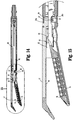
Fig. 1A is a perspective view of a reload according to an embodiment of the instant disclosure, the reload configured for use with a surgical apparatus that is shown schematically inFig. 1A ; -
Fig. 1B is a perspective view of one type of surgical stapler that may be utilized with the reload shown inFig. 1A ; -
Fig. 2 is an exploded view of the reload shown inFig. 1A with parts separated; -
Fig. 3 is a perspective view of a firing cam bar assembly of the reload shown inFigs. 1 and2 ; -
Fig. 4 is the indicated area of detail shown inFig. 3 ; -
Fig. 5 is a side view of the firing cam bar assembly shown inFig. 3 ; -
Fig. 6 is an exploded view of the firing cam bar assembly shown inFig. 3 with parts separated; -
Fig. 7 is the indicated area of detail shown inFig. 1A ; -
Fig. 8 is a perspective view of the reload shown inFig. 1A with an outer tube of the reload removed; -
Fig. 9 is the indicated area of detail shown inFig. 8 ; -
Fig. 10 is a perspective view of the reload shown inFig. 1A with parts removed illustrating the firing cam bar assembly coupled to a cartridge of a tool assembly of the reload; -
Fig. 11 is the indicated area of detail shown inFig. 10 ; -
Fig. 12 is a perspective view of the reload shown inFig. 1A with parts removed illustrating a cantilever of the cartridge in contact with the firing cam bar assembly; -
Fig. 13 is the indicated area of detail shown inFig. 12 ; -
Fig. 14 is a cross sectional view taken along section line 14-14 inFig. 1A ; -
Fig. 15 is the indicated area of detail shown inFig. 14 ; -
Fig. 16 is a partial, cross sectional view of a distal end of the reload shown inFig. 1A illustrating the firing cam bar assembly being translated through the cartridge to fire fasteners of the cartridge; -
Fig. 17 is the indicated area of detail shown inFig. 16 ; -
Fig. 18 is a partial, cross sectional view of the distal end of the reload shown inFig. 15 illustrating a cam surface of the firing cam bar assembly sliding along the cantilever of the cartridge as the firing cam bar assembly is being translated through the cartridge to fire fasteners of the cartridge; -
Fig. 19 is a partial, cross sectional view of the distal end of the reload shown inFig. 15 illustrating a pusher contacting surface of the firing cam bar assembly pushing a pusher of the cartridge as the firing cam bar assembly is being translated through the cartridge to fire fasteners of the cartridge; -
Fig. 20 is a partial, cross sectional view of the distal end of the reload shown inFig. 15 illustrating the cam surface of the firing cam bar assembly and the cantilever of the cartridge in contact with one another to maintain a specific tissue gap distance between the cartridge and an anvil of the tool assembly; -
Fig. 21 is a perspective view of a reload according to another embodiment of the instant disclosure, the reload configured for use with the surgical apparatus that is shown schematically inFig. 1A ; -
Fig. 22 is an exploded view of the reload shown inFig. 21 with parts separated; -
Fig. 23 is a perspective view of a cartridge assembly of the reload shown inFig, 21 ; -
Fig. 24 is an exploded view of the cartridge assembly shown inFig. 23 with parts separated; -
Fig. 25 is a perspective view of a second jaw member of the reload shown inFig. 21 ; -
Fig. 26 is an exploded view of the second jaw member shown inFig. 25 with parts separated; -
Fig. 27 is a perspective view of a drive beam assembly and latch assembly of the reload shown inFig. 21 ; -
Fig. 28 is an exploded view of the drive beam and latch assembly shown inFig. 27 with parts separated; -
Fig. 29 is a perspective view of a sled pusher assembly of the reload shown inFig. 21 ; -
Fig. 30 is an exploded view of the sled pusher assembly shown inFig. 29 with parts separated; -
Fig. 31 is a partial, perspective view of the reload shownFig. 21 with a distal end of the reload shown in an unclamped configuration; -
Fig. 32 is a partial, perspective view of the reload shown inFig. 21 with parts removed illustrating the drive beam assembly and latch assembly when the distal end of the reload is in the unclamped configuration shown inFig. 31 ; -
Fig. 33 is the indicated area of detail shown inFig. 32 ; -
Fig. 34 is a cross sectional view taken along section line 34-34 inFig. 31 ; -
Fig. 35 is the indicated area of detail shown inFig. 34 ; -
Fig. 36 is a partial, perspective view of the reload shown inFig. 21 with a distal end of the reload shown in a clamped configuration; -
Fig. 37 is a partial, perspective view of the reload shown inFig. 21 with parts removed illustrating the drive beam assembly and latch assembly when the distal end of the reload is in the clamped configuration shown inFig. 36 ; -
Fig. 38 is the indicated area of detail shown inFig. 37 ; -
Fig. 39 is a perspective view of an upper shaft portion of the reload shown inFig. 21 ; -
Fig. 40 is a cross sectional view of the reload shown inFig. 21 with the distal end of the reload shown in the clamped configuration; -
Fig. 41 is the indicated area of detail shown inFig. 40 ; -
Fig. 42 is a partial, perspective view of the reload shown inFig. 21 with parts removed illustrating the sled pusher assembly shown inFig. 29 as the sled pusher assembly is being fired; -
Fig. 43 is a cross sectional view of the reload shown inFig. 21 with the reload shown in the clamped configuration and the sled pusher assembly being fired; and -
Fig. 44 is the indicated area of detail shown inFig. 43 . - Detailed embodiments of the present disclosure are disclosed herein; however, the disclosed embodiments are merely examples of the disclosure, which may be embodied in various forms. Therefore, specific structural and functional details disclosed herein are not to be interpreted as limiting, but merely as a basis for the claims and as a representative basis for teaching one skilled in the art to variously employ the present disclosure in virtually any appropriately detailed structure.
- Embodiments of the present disclosure are described in detail with reference to the drawing figures wherein like reference numerals identify similar or identical elements. As used herein, the term "distal" refers to the portion that is being described which is further from a user, while the term "proximal" refers to the portion that is being described which is closer to a user.
- Referring initially to
Fig. 1A , a reload 10 in accordance with the present disclosure is shown. The reload 10 may be configured to be coupled to a variety of different surgical actuating devices, shown schematically as 12 inFig. 1A , including manually operated actuation devices, robotically controlled actuation devices, electromechanical actuation devices, motorized actuation devices, etc. Thesurgical actuating device 12 includes ashaft assembly 16 having a distal end configured to releasably support the reload 10. - In one embodiment illustrated in
Fig. 1B , thesurgical actuating device 12 is a manually operatedstapler 212 which includes ahandle assembly 214 and ashaft assembly 216 that engages and supports the reload 10. Thehandle assembly 214 includes a pair ofretraction knobs 218 that is configured to return thestapler 212 to a retracted configuration. For a more detailed description of the operation and the operative components of thestapler 212, reference is made to commonly-ownedU.S. Patent No. 5,865,361 to Milliman, the entire contents of which are hereby incorporated by reference. -
Fig. 2 is a perspective view of the reload 10 with parts separated. The reload 10 includes anouter tube 18 that houses ashaft assembly 20 configured to couple the reload 10 to theshaft assembly 16 of the actuating device 12 (seeFig. 1A ). Theshaft assembly 20 includes anupper housing portion 22a andlower housing portion 22b that, when coupled to one another, house components of the reload 10. Proximal ends 24a, 24b of the upper andlower housing portions shaft assembly 16 of the actuating device 12 (e.g., see the '361 patent). A distal end of thehousing portions shaft assembly 20 supports upper andlower coupling members coupling members lower pivot portions Fig. 1A ). An articulatinglink 32 is slidably positioned within the upper andlower housing portions tool assembly 14 of the reload 10 in relation to theshaft assembly 20. - The
tool assembly 14 includes afirst jaw member 13 that supports acartridge 15 and asecond jaw member 17 that supports ananvil 19. Thefirst jaw member 13 is pivotally supported in relation to thesecond jaw member 17 between spaced and approximated positions. Thecartridge 15 houses a plurality ofpushers 9 andfasteners 11. A dissecting tip 19a may be secured to a distal end of theanvil 19 to facilitate positioning of theanvil 19 in relation to tissue to be stapled. Such a dissecting tip 19a is described inU.S. Patent No. 8,348,123 which is hereby incorporated herein by reference. - Referring also to
Figs. 3-6 , theshaft assembly 20 includes a firingcam bar assembly 34 that is releasably engaged with a central rod (not shown) of theactuating device 12. The firingcam bar assembly 34 is configured to move thecartridge 15 from the spaced position (Fig. 1B ) towards theanvil 19 to the approximated position (Fig. 18 ) as the firingcam bar assembly 34 is translated distally through thetool assembly 14. A distal end of the firingcam bar assembly 34 is also configured to push the plurality ofpushers 9 to fire the plurality offasteners 11 from thecartridge 15 as the firingcam bar assembly 34 is translated through thecartridge 15 as will be described in further detail below. - The firing
cam bar assembly 34 includes a firstfiring cam bar 36 having an elongated configuration defined by left andright sidewalls distal end 38. Each of the left andright sidewalls cam bar 36 includes acam surface 33 having afirst cam portion 39 and asecond cam portion 40. Each of thefirst cam portions 39 is disposed distally and at an angle in relation to one of thesecond cam portions 40 which is defined along a bottom/lower surface of the left andright sidewalls second cam portions 40 can be seen inFigs. 3-5 . The configuration of thefirst cam portions 39 of thecam surface 33 facilitates movement of thefirst jaw member 13 towards thesecond jaw member 17 from the spaced position to the approximated position so that tissue may be clamped as will be described in further detail below. Thesecond cam portions 40 are elongated in comparison to thefirst cam portions 39 and taper inwardly a distance "T" (Fig. 5 ) in relation to a longitudinal axis "B-B" of the firingcam bar assembly 34 toward a proximal end of the firing cam bar assembly 34 (Fig. 5 ). The taper "T" controls a tissue gap distance between the first andsecond jaw members second jaw members - The
distal end 38 of the firstfiring cam bar 36 includes twopusher contacting surfaces Figs. 4 and6 ) which are aligned with the plurality ofpushers 9 of the cartridge 15 (Fig. 19 ). Thepusher contacting surfaces pushers 9 to deploy the plurality ofsurgical fasteners 11 from thecartridge 15. - In the illustrated embodiment, the firing
cam bar assembly 34 includes a second or innerfiring cam bar 44 that is similar to the firstfiring cam bar 36. The first and second firing cam bars 36, 44 form a nested configuration with one another (as best shown inFig. 6 ). The secondfiring cam bar 44 has an elongated configuration defined by left andright sidewalls distal end 46. Each of the left andright sidewalls cam bar 44 includes a cam surface 53 having afirst cam portion 49 andsecond cam portion 50. Thefirst cam portions 49 of the cam surface 53 are disposed distally and at an angle in relation to the second cam portions 50 (only one of thesecond portions 50 is shown) of the cam surface 53. Thedistal end 46 of the secondfiring cam bar 44 includes twopusher contacting surfaces pushers 9 of thecartridge 15 to contact the plurality ofpushers 9 to deploy the plurality ofsurgical fasteners 11 from the cartridge 15 (Fig. 19 ). - The first and second firing cam bars 36, 44 may be formed from any suitable material including, but not limited to, plastic, metal, etc. In embodiments, the first and second firing cam bars 36, 44 are formed from metal.
- While the firing
cam bar assembly 34 has been described herein as including first and second firing cam bars 36, 44, greater or fewer firing cam bars may be utilized. For example, in embodiments, the secondfiring cam bar 44 may be omitted. In this particular embodiment, the configuration of the firstfiring cam bar 36 of the firingcam bar assembly 34 may be modified to include features of the secondfiring cam bar 44. For example, the left andright sidewalls firing cam bar 36 may be widened at thedistal end 38 to align with all of the rows of the plurality ofpushers 9 for ejecting all of the plurality offasteners 11 disposed within thecartridge 15. Alternately, the secondfiring cam bar 44 can be omitted with no change to the configuration of the firstfiring cam bar 36. - Referring to
Figs. 7-13 , a cantilever 52 (Fig. 13 ) is provided at a proximal end of thefirst jaw member 13. Thecantilever 52 may be monolithically formed with thefirst jaw member 13. Alternatively, thecantilever 52 may be formed as a separate component apart from thefirst jaw member 13 and coupled to thefirst jaw member 13 via one or more suitable coupling methods, e.g., welding. Thecantilever 52 is disposed adjacent thepivot assembly 30 between thelower coupling member 26b and a distal end of the articulating link 32 (seeFig. 9 for example). - In the illustrated embodiment, the
cantilever 52 is in the form of abridge 54 that is formed betweenside projections Fig. 13 ). Thebridge 54 is disposed transverse to a longitudinal axis "A-A" (Fig. 7 ) defined through theshaft assembly 20 of the reload 10. - The
bridge 54 supports a cam member 57 (Fig. 2 and13 ) which is positioned to be slidably engaged by the first andsecond cam portions cam bar assembly 34 is advanced distally within thecartridge 15, as will be described in greater detail below. Thecam member 57 may be slanted (as shown in the illustrated embodiment) or otherwise configured to operate in conjunction with the taper "T" of thesecond cam portions second jaw members second jaw members cam member 57 may be coupled to thebridge 54 via one or more suitable coupling methods, e.g., adhesive, welding, etc. Alternatively, thecam member 57 may be omitted and thebridge 54 may be integrally formed with a cam surface configured to control the size of the tissue gap. In accordance with the instant disclosure, thebridge 54 engages the firing cam bars 36, 44 to close the first andsecond jaw members - Referring to
Fig. 9 , thecantilever 52 defines anaperture 58 between theside projections bridge 54. Theaperture 58 receives a rivet 59 (Fig. 9 ) for coupling thelower coupling member 26b to thelower portion 28b of thepivot assembly 30 during manufacture of the reload 10. - Referring to
Figs. 2 ,14, and 15 , aresilient member 56 is provided on thecartridge 15 and is positioned to bias thecartridge 15 radially away from theanvil 19 towards the spaced position. Theresilient member 56 includes aproximal end 60 that is coupled to a proximal end of thecartridge 15 and adistal end 62 that is positioned to contact at least a portion of theanvil 19. In the illustrated embodiment, theproximal end 60 of theresilient member 56 includes twofinger portions apertures Fig. 2 andFig. 13 ). - Referring to
Figs. 16 and 17 , in use, prior to positioning tissue between the first andsecond jaw members tool assembly 14 is in the spaced or unapproximated position. In this position, the distal ends 38, 46 of the first and second firing cam bars 36, 44 are positioned proximally of the plurality ofpushers 9 and the plurality offasteners 11. In addition, in this configuration an engagement portion of thefirst cam portions 39, 49 (see alsoFig. 6 ) of the first and second firing cam bars 36, 44 is positioned proximally of thecam member 57. As discussed above, theresilient member 56 is positioned to urge thejaw member 13 to the spaced or unapproximated position. - Referring to
Fig. 18 , when the firingcam bar assembly 34 is advanced distally, thefirst cam portions cam member 57 of thebridge 54 and pivot thefirst jaw member 13 including thecartridge 15 towards theanvil 19 of thesecond jaw member 17 to move thejaw member 13 including thecartridge 15 to the clamped or approximated configuration. In this example, the cartridge is pivotably attached to the second jaw member. However, any of the embodiments disclosed herein can have a first jaw member, or second jaw member, or both that are pivotably movable. - Referring to
Fig. 19 , continued distal translation of the firingcam bar assembly 34 moves the distal ends 36, 48 of the first and second firing cam bars 36, 44 into contact with the plurality ofpushers 9 sequentially to eject the plurality offasteners 11 from thecartridge 15 and into theanvil 19 to staple clamped tissue. In accordance with the present disclosure, as the firingcam bar assembly 34 is translated through thecartridge 15, engagement of thecam member 57 on thebridge 54 with the taper "T" (Fig. 15 ) on thesecond cam portions jaw member 17 in relation to thejaw member 13 to selectively maintain a desired tissue gap distance between the first andsecond jaw members 13, 17 (Fig. 20 ). In accordance with the instant disclosure, the degree of the taper "T" on thesecond cam portions cam bar assembly 34 through thecartridge 15. It is noted that the taper "T" may define a positive or negative slope in the proximal direction to provide the proper or desired tissue gap distance. - The unique configuration of the
jaw member 13 including the firingcam bar assembly 34 andcantilever 52 provides a simple design for approximating and controlling the tissue gap between thecartridge 15 and theanvil 19. Additionally, the presently disclosedtool assembly 14 allows for the tissue gap between the first andsecond jaw members second cam portions cam bar assembly 34 is advanced. - In embodiments, the
tool assembly 14 can be integrally formed with thesurgical actuating device 12. In this particular embodiment, thetool assembly 14 can be operably coupled to an articulating assembly, e.g., the articulatingassembly 30, which may be supported at a distal end of theshaft assembly 16 of thesurgical actuating device 12. Alternatively, the articulatingassembly 30 can be omitted and thetool assembly 14 can be directly connected to the distal end of theshaft assembly 16 of thesurgical actuating device 12. -
Figs. 21-44 illustrate a reload 110 according to another embodiment of the instant disclosure. The reload 110 is configured for use with thestapler 212 that is shown inFig. 1B . Only the features that are unique to the reload 110 are described herein. -
Fig. 22 is a perspective view of the reload 110 with parts separated. The reload includes anouter tube 118 that houses ashaft assembly 120 configured to couple the reload 110 with theshaft assembly 216 of theactuating device 212 shown inFig. 1B . Theshaft assembly 120 includesupper housing portion 122a andlower housing portion 122b that, when coupled to one another, house components of the reload 110. Proximal ends 124a, 124b of the upper andlower housing portions shaft assembly 216 of the actuating device 212 (see '361 patent for example). A distal end of theshaft assembly 120 includes a pair of upper andlower coupling members shaft assembly 120 to the upper andlower pivot portions Fig. 21 ). An articulatinglink 132 is slidably positioned within the upper andlower housing portions tool assembly 114 of the reload 110 relative to a longitudinal axis "C-C" (Fig. 21 ) defined through theshaft assembly 120. - Referring to
Figs. 22-24 , thetool assembly 114 includes afirst jaw member 113 that supports acartridge 115 housing a plurality ofpushers 109 andfasteners 111 and asecond jaw member 117 that supports ananvil 119. Thecartridge 115 supports aresilient member 156 which is positioned to bias thecartridge 115 radially away from theanvil 119 towards an unapproximated or spaced configuration. Theresilient member 156 includes a base portion 160 (Fig. 24 ) that couples to a proximal end of thecartridge 115 and anupper portion 162 positioned to contact at least a portion of theanvil 119. Thebase portion 160 of theresilient member 156 is seated within acorresponding slot 165 defined at the proximal end of thecartridge 115 and includes one or more detents 163 (onedetent 163 is shown in the figures) which is received in acorresponding indent 166 disposed on thecartridge 115 adjacent theslot 165 to couple theresilient member 156 to thecartridge 115. - Referring to
Figs. 25 and 26 , thesecond jaw member 117 includes a pair ofupper rails interior wall portion 123 of thesecond jaw member 117. Theupper rails elongated slot 125 which extends along the length of theupper rails upper rails interior wall portion 123 proximal to where thetop portion 162 of theresilient member 156 contacts theinterior wall portion 123 of the jaw member 117 (seeFig. 35 for example). A dissecting tip 157, such as disclosed in the '123 patent, may be secured to a distal end of thesecond jaw member 117 to facilitate positioning of thesecond jaw member 117 in relation to tissue to be stapled. - Referring also to
Figs. 27 and 28 , the reload 110 (Fig. 21 ) includes adrive beam assembly 134 formed from a plurality ofdrive beam portions 135 that are coupled to one another to form adrive beam 136. A working end of thedrive beam assembly 134 includes an I-beam 137 which is coupled to the distal end of thedrive beam portions 135 and includes upper andlower flanges strut 139c. Unlike conventional I-beams, the I-beam 137 does not include a knife or cutting blade at a leading edge of thestrut 139c, as the I-beam 137 is not configured to sever stapled tissue. The I-beam 137 is translatable through thetool assembly 114 to approximate the first andsecond jaw members fasteners 111 from thecartridge 115 as will be described in further detail below. Theupper flange 139a is positioned within the second jaw member 117 (Fig. 26 ) above theupper rails drive beam 136 of thedrive beam assembly 134 is translated distally within thesecond jaw member 117, the upper flange 139 slides atop theupper flange 139a to prevent outward movement of thesecond jaw member 117 in relation to thefirst jaw member 113. Similarly, thestrut 139c of the I-beam is positioned through an elongated slot 127 (seeFig. 31 ) that is defined through thefirst jaw member 113 such that thelower flange 139b is slidable along an exterior surface of thefirst jaw member 113 to prevent outward movement of thefirst jaw member 113 in relation to thesecond jaw member 117. Anotch 129 is defined through a side wall of thestrut 139c, the significance of which is described in greater detail below. - A
latch assembly 140 is coupled to a proximal end of thedrive beam assembly 134. Thelatch assembly 140 includes alatch body 141 including acollar 142 defining bottom and top slots 144 (only thetop slot 144 is shown). Theslots 144 are configured to receive a proximal end of thedrive beam 136. Alongitudinal aperture 146 of suitable configuration is defined through thecollar 142 and is in general alignment with an elongatedproximal portion 148 of thelatch body 141. Thelatch body 141 of thelatch assembly 140 includes a pair of opposingsupport members pivot pin 151. Aprotrusion 170 extends upwardly from the latch body of thelatch assembly 140 adjacent thecollar 142 and is configured to support aspring 171. - The
latch assembly 140 includes alatch 150 having a generally elongated configuration including adistal portion 152, amedial portion 154 and aproximal portion 158. Atransverse aperture 153 extends through themedial portion 154 and is configured to receive thepivot pin 151 for pivotally securing thelatch 150 to thelatch body 141 of thelatch assembly 140. Thedistal portion 152 of thelatch 150 is positioned to contact thespring 171 such that thespring 171 urges aproximal end 172 of theproximal portion 158 of thelatch 150 downwardly towards theproximal portion 148 of the latch assembly 140 (as best shown inFig. 27 ). Aprotrusion 164 is provided on a bottom surface and at theproximal end 172 of theproximal portion 158 of thelatch assembly 150. A lateral offsetextension 173 is also provided at theproximal end 172 of thelatch assembly 150 and is configured to move thelatch 150 upwardly against the bias of thespring 171, as will be described in greater detail below. - Referring to
Figs. 29 and30 , asled pusher assembly 174 is illustrated. Thesled pusher assembly 174 includes anelongated support member 176 which has a distal end that engages asled pusher 178 and a proximal end which supports acoupling assembly 180. The distal end of thesupport member 176 defines aslit 181 and a pair of apertures 182 (only oneaperture 182 is shown). Theapertures 182 extend through theslit 181 and receive apin 183, rivet or the like. Theslit 181 is configured to receive a proximal end of thesled pusher 178. Thepin 183 extends through anaperture 186 defined through the proximal end of thesled pusher 178 to secure thesled pusher 178 to thesupport member 176. As can be appreciated other coupling methods could also be utilized to couple thesled pusher 178 to thesupport member 176. - An
aperture 184 is provided on thesupport member 176. Theaperture 184 is configured to receive theprotrusion 164 of thelatch 150 such that theprotrusion 164 contacts aproximal wall portion 185 defining the aperture 184 (Fig. 33 ). In accordance with the instant disclosure, when theprotrusion 164 is in contact with theproximal wall portion 185, thesled pusher assembly 174 and the and thedrive beam assembly 134 are releasably coupled to one another such that movement ofsled pusher assembly 174 effects corresponding movement of thedrive beam assembly 134 to effect movement of thefirst jaw member 113 towards thesecond jaw member 117. - Referring also to
Figs. 32 and33 , thelower housing portion 122b supports thedrive assembly 134 including thelatch assembly 140 and thesled pusher assembly 174. Thelower housing portion 122b is configured to disengage thelatch 150 of thelatch assembly 140 from thesled pusher assembly 174 to allow further distal translation of thesled pusher assembly 174 independently of thedrive beam assembly 134. Specifically, aramp portion 188 is provided along atop wall 189 of thelower housing portion 122b. Theramp portion 188 is configured to contact the lateral offsetextension 173 of thelatch 150 to pivot thelatch 150 aboutpivot member 151 to raise theprotrusion 164 of thelatch 150 out from engagement with theaperture 184 of thesupport member 176 of thesled pusher assembly 174 when thedrive beam assembly 134 andsled pusher assembly 174 are translated distally to approximate thejaw members - A pair of
stops 190a are provided along aninterior wall portion 191 of thelower housing portion 122b.Stops 190a are positioned to contact a lower portion of thecollar 142 of thelatch assembly 140 to prevent further distal translation of thedrive beam assembly 134 after thecollar 142 engages thestops 190a. In the illustrated embodiment, a corresponding pair ofstops 190b (Fig. 39 ) is provided on theupper housing portion 122a and is configured to contact an upper portion of thecollar 142 of thelatch assembly 140 to prevent further distal translation of thedrive beam assembly 134 after thecollar 142 engages thestops 190a. -
Figs. 34-44 illustrate the operation of the reload 110. Referring toFigs. 33-35 , prior to positioning tissue between the first andsecond jaw members tool assembly 114 is urged to the spaced or unapproximated position by theresilient member 156 which contacts theinterior wall 123 of the second jaw member 117 (Figs. 34 and 35 ). In the spaced position, theprotrusion 164 of thelatch 150 is in contact with theproximal wall portion 185 defining theaperture 184 in thesupport member 176 to releasably couple thesled pusher assembly 174 to thedrive beam assembly 134 such that distal translation of thesled pusher assembly 174 effects corresponding movement of thedrive beam assembly 134. - In the spaced position of the
jaw members support member 176 is positioned through thelongitudinal aperture 146 of thecollar 142 of thelatch assembly 140 and thesled pusher 178 is positioned within thenotch 129 ofstrut 139c of the I-beam 137 to align adistal end 193 of thesled pusher 178 with asled 187 that is provided in the cartridge 115 (Fig. 35 ). Thedistal end 193 of thesled pusher 178 is configured to engage aproximal end 195 of thesled 187 when thesled pusher 178 is translated distally into thecartridge 115. In the illustrated embodiment, thedistal end 193 of thesled pusher 178 and theproximal end 195 of thesled 187 include complementary configurations, e.g., spherical configurations, to facilitate engagement therebetween. Thesled 187 is configured to sequentially contact the plurality ofpushers 109 to eject the plurality offasteners 111 from thecartridge 115 as is known in the art. - Referring to
Figs. 36-41 , when the surgical actuating device 12 (Fig. 1B ) is actuated to advance thesled pusher assembly 174, thedrive assembly 134 which is releasably coupled to thesled pusher assembly 174 is advanced distally to move the I-beam 137 distally in relation to thetool assembly 114. As the I-beam is moved distally, the upper andlower flanges beam 137 engage the first andsecond jaw members first jaw member 113 is moved towards thesecond jaw member 117 to the clamped or approximated position of thetool assembly 114 to clamp tissue (Fig. 36 ). As noted above, thedrive assembly 134 and thesled pusher assembly 174 move in unison as a result of theprotrusion 164 being in contact with theproximal wall portion 185 defining theaperture 184 of thesupport member 176. - As the
drive assembly 134 is moved distally to move thejaw members Fig. 38 ) of thelatch 150 slides up along theramp 188 of thelower housing portion 122b and raises thelatch 150 to disengage theprotrusion 164 of thelatch 140 from engagement with theproximal wall portion 185 of thesupport member 176. In the approximated position of thejaw members sled pusher assembly 174 is uncoupled from thedrive assembly 134 and thedistal end 193 of thesled pusher 178 is positioned in engagement with theproximal end 195 of the sled 187 (as best shown inFig. 41 ). - In the approximated position, the
collar 142 is in contact with thestops 190a in thelower housing portion 122b (Figs. 38 and42 ) and the upper portion of thecollar 142 is in contact with thestops 190b in theupper housing portion 122a. Engagement betweenstops 190a andcollar 142 prevents further distal movement of thedrive beam assembly 134. - Referring to
Figs. 42-44 , after thesled pusher assembly 174 is uncoupled from thedrive assembly 134, further actuation of theactuating device 12 effects independent movement of thesled pusher assembly 174 through theaperture 146 of thecollar 142 such that thedistal end 193 of thesled pusher 178 moves distally in relation to the I-beam 137 of thedrive assembly 134 to advance thesled 187 through thecartridge 115 into sequential engagement with thepushers 109 to eject the plurality offasteners 111 from the cartridge 115 (Figs. 43 and 44 ). - While the
reloads stapler 212, it is within the purview of the present disclosure that the operative components of thereloads - The
stapler 212 with either of thereloads stapler 212 can be utilized to staple (i.e., occlude) this vascular structure, thereby controlling and/or inhibiting blood flow through the vascular structure. It is contemplated that thestapler 212 with either of thereloads - While several embodiments of the disclosure have been shown in the drawings, it is not intended that the disclosure be limited thereto, as it is intended that the disclosure be as broad in scope as the art will allow and that the specification be read likewise. Therefore, the above description should not be construed as limiting, but merely as exemplifications of particular embodiments. Those skilled in the art will envision other modifications within the scope and spirit of the claims appended hereto.
- The invention may be described by reference to the following numbered paragraphs:-
- 1. A surgical stapling apparatus, comprising:
- an actuating device including an elongated shaft;
- a tool assembly disposed on a distal end of the shaft, the tool assembly including a first jaw member supporting a cartridge assembly having a plurality of fasteners and a sled positioned to eject the fasteners from the cartridge assembly and a second jaw member supporting an anvil, the first jaw member being movable in relation to the second jaw member between spaced and approximated positions;
- a sled pusher assembly including a sled pusher having a distal end configured to engage the sled of the cartridge assembly; and
- a drive beam assembly including a latch assembly having a latch releasably coupled to the sled pusher assembly,
- 2. The surgical stapling apparatus according to paragraph 1, wherein the latch assembly includes a collar which is coupled to a proximal end of the drive beam assembly and includes an aperture configured to receive a support member of the sled pusher assembly.
- 3. The surgical stapling apparatus according to
paragraph 2, wherein the support member of the sled pusher assembly includes at least one aperture that is configured to receive the latch of the latch assembly. - 4. The surgical stapling apparatus according to paragraph 1, wherein the drive beam assembly includes an I-beam having a sidewall defining a notch, the sled pusher being received within the notch.
- 5. The surgical stapling apparatus according to
paragraph 4, wherein the I-beam is positioned to cam the first and second jaw members to the approximated position when the drive beam assembly is translated distally. - 6. The surgical stapling apparatus according to paragraph 3, wherein the latch assembly includes at least one spring configured to bias the latch of the latch assembly into the aperture defined in the support member of the sled pusher assembly.
- 7. The surgical stapling apparatus according to paragraph 6, wherein the aperture of the support member is defined by a proximal wall portion of the sled pusher assembly, the proximal wall portion being configured to engage the latch of the latch assembly to maintain the drive beam assembly and the sled pusher coupled with one another.
- 8. The surgical stapling apparatus according to
paragraph 2, wherein the elongated shaft includes upper and lower housing portions, and at least one of the upper and lower housing portions includes at least one stop member configured to contact a proximal end of the collar of the latch assembly when the drive beam assembly is translated distally. - 9. The surgical stapling apparatus according to paragraph 8, wherein the latch includes a lateral offset extension, and wherein at least one of the upper and lower housing portions of the elongated shaft includes at least one ramp portion configured to be engaged by the lateral offset extension to effect movement of the latch out of engagement with the proximal wall portion when the drive beam assembly is moved distally so as to allow the sled pusher assembly to move distally in relation to the drive beam assembly.
- 10. The surgical stapling apparatus according to paragraph 1, wherein a resilient member is provided on the cartridge assembly for biasing the cartridge assembly radially away from the anvil.
- 11. The surgical stapling apparatus according to
paragraph 10, wherein the resilient member includes a bottom portion that is coupled to a proximal end of the cartridge assembly and a top portion that is positioned to contact at least a portion of the anvil. - 12. The surgical stapling apparatus according to
paragraph 11, wherein the bottom portion of the resilient member is seated within a corresponding slot defined at the proximal end of the cartridge assembly. - 13. The surgical stapling apparatus according to
paragraph 12, wherein the bottom portion of the resilient member includes at least one detent that couples to a corresponding indent disposed on the cartridge assembly adjacent the slot. - 14. The surgical stapling apparatus according to paragraph 1, wherein the tool assembly is removably couplable to the distal end of the shaft of the surgical stapling apparatus.
- 15. A reload configured for use with a surgical stapling apparatus, the reload comprising:
- a shaft including a proximal end and distal end, the proximal end adapted to couple to a surgical apparatus;
- a tool assembly disposed on the distal end of the shaft, the tool assembly including a first jaw member supporting a cartridge assembly having a plurality of fasteners and a sled positioned to eject the fasteners from the cartridge assembly and a second jaw member supporting an anvil, the first jaw member being movable in relation to the second jaw member between spaced and approximated positions;
- a sled pusher assembly including a sled pusher having a distal end configured to engage the sled of the cartridge assembly; and
- a drive beam assembly including a latch assembly having a latch releasably coupled to the sled pusher assembly,
- 16. The reload according to
paragraph 15, wherein the latch assembly includes a collar which is coupled to a proximal end of the drive beam assembly and includes an aperture configured to receive a support member of the sled pusher assembly. - 17. The reload according to
paragraph 16, wherein the support member of the sled pusher assembly includes at least one aperture that is configured to receive the latch of the latch assembly. - 18. The reload according to
paragraph 15, wherein the drive beam assembly includes an I-beam having a side wall defining a notch, the sled pusher being received within the notch. - 19. The reload according to
paragraph 18, wherein the I-beam is positioned to cam the first and second jaw members to the approximated position when the drive beam assembly is translated distally. - 20. The reload according to
paragraph 17, wherein the latch assembly includes at least one spring configured to bias the latch of the latch assembly into the aperture defined in the support member of the sled pusher assembly. - 21. The reload according to
paragraph 20, wherein the aperture of the support member is defined by a proximal wall portion of the sled pusher assembly, the proximal wall portion being configured to engage the latch of the latch assembly to maintain the drive beam assembly and the sled pusher coupled with one another. - 22. The reload according to
paragraph 16, wherein the elongated shaft includes upper and lower housing portions, and at least one of the upper and lower housing portions includes at least one stop member configured to contact a proximal end of the collar of the latch assembly when the drive beam assembly is translated distally. - 23. The reload according to
paragraph 22, wherein the latch includes a lateral offset extension, and wherein at least one of the upper and lower housing portions of the elongated shaft includes at least one ramp portion configured to be engaged by the lateral offset extension to effect movement of the latch out of engagement with the proximal wall portion when the drive beam assembly is moved distally so as to allow the sled pusher assembly to move distally in relation to the drive beam assembly. - 24. The reload according to
paragraph 15, wherein a resilient member is provided on the cartridge assembly for biasing the cartridge assembly radially away from the anvil. - 25. The reload according to
paragraph 24, wherein the resilient member includes a bottom portion that is coupled to a proximal end of the cartridge assembly and a top portion that is positioned to contact at least a portion of the anvil. - 26. The reload according to paragraph 25, wherein the bottom portion of the resilient member is seated within a corresponding slot defined at the proximal end of the cartridge assembly.
- 27. The reload according to paragraph 26, wherein the bottom portion of the resilient member includes at least one detent that couples to a corresponding indent disposed on the cartridge assembly adjacent the slot.
- The invention may also be described by reference to the following numbered paragraphs:-
- 1. A surgical stapling apparatus, comprising:
- an actuating device including an elongated shaft;
- a tool assembly disposed on a distal end of the shaft, the tool assembly including a first jaw member supporting a cartridge assembly having a plurality of fasteners and a sled positioned to eject the fasteners from the cartridge assembly and a second jaw member supporting an anvil, the first jaw member being movable in relation to the second jaw member between spaced and approximated positions;
- a sled pusher assembly including a sled pusher having a distal end configured to engage the sled of the cartridge assembly; and
- a drive beam assembly including a latch assembly having a latch releasably coupled to the sled pusher assembly,
- 2. The surgical stapling apparatus according to paragraph 1, wherein the latch assembly includes a collar which is coupled to a proximal end of the drive beam assembly and includes an aperture configured to receive a support member of the sled pusher assembly; preferably wherein the support member of the sled pusher assembly includes at least one aperture that is configured to receive the latch of the latch assembly.
- 3. The surgical stapling apparatus according to paragraph 1 or
paragraph 2, wherein the drive beam assembly includes an I-beam having a sidewall defining a notch, the sled pusher being received within the notch; preferably wherein the I-beam is positioned to cam the first and second jaw members to the approximated position when the drive beam assembly is translated distally. - 4. The surgical stapling apparatus according to
paragraph 2, wherein the latch assembly includes at least one spring configured to bias the latch of the latch assembly into the aperture defined in the support member of the sled pusher assembly; preferably wherein the aperture of the support member is defined by a proximal wall portion of the sled pusher assembly, the proximal wall portion being configured to engage the latch of the latch assembly to maintain the drive beam assembly and the sled pusher coupled with one another. - 5. The surgical stapling apparatus according to
paragraph 2, wherein the elongated shaft includes upper and lower housing portions, and at least one of the upper and lower housing portions includes at least one stop member configured to contact a proximal end of the collar of the latch assembly when the drive beam assembly is translated distally; preferably wherein the latch includes a lateral offset extension, and wherein at least one of the upper and lower housing portions of the elongated shaft includes at least one ramp portion configured to be engaged by the lateral offset extension to effect movement of the latch out of engagement with the proximal wall portion when the drive beam assembly is moved distally so as to allow the sled pusher assembly to move distally in relation to the drive beam assembly. - 6. The surgical stapling apparatus according to any preceding claim, wherein a resilient member is provided on the cartridge assembly for biasing the cartridge assembly radially away from the anvil; preferably wherein the resilient member includes a bottom portion that is coupled to a proximal end of the cartridge assembly and a top portion that is positioned to contact at least a portion of the anvil; preferably still wherein the bottom portion of the resilient member is seated within a corresponding slot defined at the proximal end of the cartridge assembly.
- 7. The surgical stapling apparatus according to paragraph 6, wherein the bottom portion of the resilient member includes at least one detent that couples to a corresponding indent disposed on the cartridge assembly adjacent the slot.
- 8. The surgical stapling apparatus according to any preceding paragraph, wherein the tool assembly is removably couplable to the distal end of the shaft of the surgical stapling apparatus.
- 9. A reload configured for use with a surgical stapling apparatus, the reload comprising: a shaft including a proximal end and distal end, the proximal end adapted to couple to a surgical apparatus;
a tool assembly disposed on the distal end of the shaft, the tool assembly including a first jaw member supporting a cartridge assembly having a plurality of fasteners and a sled positioned to eject the fasteners from the cartridge assembly and a second jaw member supporting an anvil, the first jaw member being movable in relation to the second jaw member between spaced and approximated positions;
a sled pusher assembly including a sled pusher having a distal end configured to engage the sled of the cartridge assembly; and
a drive beam assembly including a latch assembly having a latch releasably coupled to the sled pusher assembly,
wherein distal translation of the drive beam assembly from a retracted position towards an advanced position effects movement of the first and second jaw members to the approximated position and disengages the latch of the latch assembly from the sled pusher assembly to facilitate distal movement of the sled pusher independently of the drive beam assembly and wherein distal movement of the sled pusher independently of the drive beam assembly advances the distal end of the sled pusher into engagement with the sled of the cartridge assembly to eject the plurality of fasteners from the cartridge assembly. - 10. The reload according to
paragraph 9, wherein the latch assembly includes a collar which is coupled to a proximal end of the drive beam assembly and includes an aperture configured to receive a support member of the sled pusher assembly; preferably wherein the support member of the sled pusher assembly includes at least one aperture that is configured to receive the latch of the latch assembly. - 11. The reload according to
paragraph 9 orparagraph 10, wherein the drive beam assembly includes an I-beam having a side wall defining a notch, the sled pusher being received within the notch; preferably wherein the I-beam is positioned to cam the first and second jaw members to the approximated position when the drive beam assembly is translated distally. - 12. The reload according to any of
paragraphs 9 to 11, wherein the latch assembly includes at least one spring configured to bias the latch of the latch assembly into the aperture defined in the support member of the sled pusher assembly; preferably wherein the aperture of the support member is defined by a proximal wall portion of the sled pusher assembly, the proximal wall portion being configured to engage the latch of the latch assembly to maintain the drive beam assembly and the sled pusher coupled with one another. - 13. The reload according to any of
paragraphs 9 to 12, wherein the elongated shaft includes upper and lower housing portions, and at least one of the upper and lower housing portions includes at least one stop member configured to contact a proximal end of the collar of the latch assembly when the drive beam assembly is translated distally; preferably wherein the latch includes a lateral offset extension, and wherein at least one of the upper and lower housing portions of the elongated shaft includes at least one ramp portion configured to be engaged by the lateral offset extension to effect movement of the latch out of engagement with the proximal wall portion when the drive beam assembly is moved distally so as to allow the sled pusher assembly to move distally in relation to the drive beam assembly. - 14. The reload according to any of
paragraphs 9 to 13, wherein a resilient member is provided on the cartridge assembly for biasing the cartridge assembly radially away from the anvil; preferably wherein the resilient member includes a bottom portion that is coupled to a proximal end of the cartridge assembly and a top portion that is positioned to contact at least a portion of the anvil. - 15. The reload according to
paragraph 14, wherein the bottom portion of the resilient member is seated within a corresponding slot defined at the proximal end of the cartridge assembly; and/or wherein the bottom portion of the resilient member includes at least one detent that couples to a corresponding indent disposed on the cartridge assembly adjacent the slot.
Claims (9)
- A reload (10) configured for use with a surgical stapling apparatus, the reload comprising:a shaft (20) including a proximal end and distal end, the proximal end adapted to couple to a surgical apparatus;a tool assembly (14) disposed on the distal end of the shaft, the tool assembly including a first jaw member (13) supporting a cartridge assembly (15) having a plurality of fasteners (11) and a plurality of pushers (9) positioned to eject the fasteners from the cartridge assembly and a second jaw member (17) supporting an anvil (19), the first jaw member being movable in relation to the second jaw member between spaced and approximated positions;a firing cam bar assembly (34) including a first firing cam bar (36) having an elongated configuration defined by left and right side walls (37a, 37b), the cam bar including a cam surface (33) having a first cam portion (39) and a second cam portion (40), the configuration of the first cam portion of the cam surface facilitating movement of the first jaw towards the second jaw member from a spaced position to an approximated position; anda cantilever (52) provided at a proximal end of the first jaw member (13), the cantilever supporting a cam member (57) positioned to be slidably engaged by the cam portions of the firing cam bar when the firing cam bar assembly is advanced distally within the cartridge; wherein, in the unapproximated position, a distal end of the firing cam bar is positioned proximally of the plurality of pushers (9) and the plurality of fasteners (11) and an engagement portion of the first cam portion of the firing cam bar is positioned proximally of the cam member (57) and, when the firing cam bar is advanced distally, the first cam portion of the firing cam bar engages the cam member (57) to pivot the first jaw member (13) including the cartridge (15) towards the anvil of the second jaw member to move the first jaw member including the cartridge to the approximated position.
- The reload of claim 1 wherein the firing cam bar assembly(34) includes a first firing cam bar (36) and a second or inner firing cam bar (44), the second firing cam bar being of a similar configuration to the first firing cam bar.
- The reload of claim 1 or claim 2 wherein the first cam portion (39) is disposed distally and at an angle in relation to the second cam portion (40) which is defined along a lower surface of the left and right sidewalls (37a, 37b).
- The reload of claim 3 wherein the second cam portion (40) is elongated in comparison to the first cam portion and tapers inwardly a distance ("T") in relation to a longitudinal axis ("B-B") of the firing cam bar assembly (34) towards a proximal end of the firing cam bar assembly thereby controlling a tissue gap distance between the first and second jaw members (13, 17) in the approximated position.
- The reload of claim 4 wherein the cam member (57) is slanted or otherwise configured to operate in conjunction with the taper ("T") of the second cam portion (40) to control the size of the tissue gap.
- The reload of any one of the preceding claims, wherein a resilient member (56) is provided on the cartridge (15) for biasing the cartridge radially away from the anvil (19) towards the spaced position.
- The reload of claim 6, wherein the resilient member (56) includes a proximal end (60) that is coupled to a proximal end of the cartridge (15) and a distal end (62) that is positioned to contact at least a portion of the anvil (19).
- The reload of claim 7, wherein the proximal end of the resilient member (56) includes two finger portions (64a, 64b) that seat within two corresponding apertures (66a, 66b) defined at the proximal end of the cartridge.
- A surgical stapling apparatus (12) comprising an actuating device including an elongated shaft (216) and a reload (10) according to any of the preceding claims, wherein the tool assembly (14) is removably couplable to a distal end of the shaft (216) of the surgical stapling apparatus.
Applications Claiming Priority (2)
| Application Number | Priority Date | Filing Date | Title |
|---|---|---|---|
| US14/166,366 US9700312B2 (en) | 2014-01-28 | 2014-01-28 | Surgical apparatus |
| EP14199678.5A EP2898837B1 (en) | 2014-01-28 | 2014-12-22 | Surgical apparatus having a sled and a drive beam with a latch |
Related Parent Applications (2)
| Application Number | Title | Priority Date | Filing Date |
|---|---|---|---|
| EP14199678.5A Division EP2898837B1 (en) | 2014-01-28 | 2014-12-22 | Surgical apparatus having a sled and a drive beam with a latch |
| EP14199678.5A Division-Into EP2898837B1 (en) | 2014-01-28 | 2014-12-22 | Surgical apparatus having a sled and a drive beam with a latch |
Publications (2)
| Publication Number | Publication Date |
|---|---|
| EP3173029A1 true EP3173029A1 (en) | 2017-05-31 |
| EP3173029B1 EP3173029B1 (en) | 2020-04-29 |
Family
ID=52231966
Family Applications (2)
| Application Number | Title | Priority Date | Filing Date |
|---|---|---|---|
| EP16192621.7A Active EP3173029B1 (en) | 2014-01-28 | 2014-12-22 | Surgical apparatus having a firing cam bar and a cantilever for approximation of the jaws |
| EP14199678.5A Active EP2898837B1 (en) | 2014-01-28 | 2014-12-22 | Surgical apparatus having a sled and a drive beam with a latch |
Family Applications After (1)
| Application Number | Title | Priority Date | Filing Date |
|---|---|---|---|
| EP14199678.5A Active EP2898837B1 (en) | 2014-01-28 | 2014-12-22 | Surgical apparatus having a sled and a drive beam with a latch |
Country Status (7)
| Country | Link |
|---|---|
| US (3) | US9700312B2 (en) |
| EP (2) | EP3173029B1 (en) |
| JP (3) | JP6480179B2 (en) |
| CN (1) | CN104799900B (en) |
| AU (1) | AU2014259515B2 (en) |
| CA (1) | CA2869044A1 (en) |
| ES (1) | ES2608390T3 (en) |
Cited By (11)
| Publication number | Priority date | Publication date | Assignee | Title |
|---|---|---|---|---|
| WO2020214397A1 (en) * | 2019-04-17 | 2020-10-22 | Intuitive Surgical Operations, Inc. | Surgical stapling instrument |
| US11439390B2 (en) | 2018-02-26 | 2022-09-13 | Intuitive Surgical Operations, Inc. | Surgical instrument with lockout mechanism |
| US11504124B2 (en) | 2017-11-29 | 2022-11-22 | Intuitive Surgical Operations, Inc. | Surgical instrument with lockout mechanism |
| US11517312B2 (en) | 2018-02-12 | 2022-12-06 | Intuitive Surgical Operations, Inc. | Surgical instrument with lockout mechanism |
| US11642129B2 (en) | 2020-01-15 | 2023-05-09 | Intuitive Surgical Operations, Inc. | Staple cartridge and drive member for surgical instrument |
| US11723661B2 (en) | 2018-12-21 | 2023-08-15 | Intuitive Surgical Operations, Inc. | Surgical instruments with switches for deactivating and/or identifying stapler cartridges |
| US11786325B2 (en) | 2019-07-02 | 2023-10-17 | Intuitive Surgical Operations, Inc. | Remotely controlling a system using video |
| US11857188B2 (en) | 2018-12-21 | 2024-01-02 | Intuitive Surgical Operations, Inc. | Articulation assemblies for surgical instruments |
| US11896224B2 (en) | 2019-05-31 | 2024-02-13 | Intuitive Surgical Operations, Inc. | Staple cartridge for a surgical instrument |
| US11944302B2 (en) | 2019-04-15 | 2024-04-02 | Intuitive Surgical Operations, Inc. | Staple cartridge for a surgical instrument |
| US11944301B2 (en) | 2018-12-21 | 2024-04-02 | Intuitive Surgical Operations, Inc. | Surgical instruments having a reinforced staple cartridge |
Families Citing this family (531)
| Publication number | Priority date | Publication date | Assignee | Title |
|---|---|---|---|---|
| US20040243151A1 (en) * | 2003-04-29 | 2004-12-02 | Demmy Todd L. | Surgical stapling device with dissecting tip |
| US9060770B2 (en) | 2003-05-20 | 2015-06-23 | Ethicon Endo-Surgery, Inc. | Robotically-driven surgical instrument with E-beam driver |
| US20070084897A1 (en) | 2003-05-20 | 2007-04-19 | Shelton Frederick E Iv | Articulating surgical stapling instrument incorporating a two-piece e-beam firing mechanism |
| US8215531B2 (en) | 2004-07-28 | 2012-07-10 | Ethicon Endo-Surgery, Inc. | Surgical stapling instrument having a medical substance dispenser |
| US11896225B2 (en) | 2004-07-28 | 2024-02-13 | Cilag Gmbh International | Staple cartridge comprising a pan |
| US7669746B2 (en) | 2005-08-31 | 2010-03-02 | Ethicon Endo-Surgery, Inc. | Staple cartridges for forming staples having differing formed staple heights |
| US9237891B2 (en) | 2005-08-31 | 2016-01-19 | Ethicon Endo-Surgery, Inc. | Robotically-controlled surgical stapling devices that produce formed staples having different lengths |
| US11484312B2 (en) | 2005-08-31 | 2022-11-01 | Cilag Gmbh International | Staple cartridge comprising a staple driver arrangement |
| US10159482B2 (en) | 2005-08-31 | 2018-12-25 | Ethicon Llc | Fastener cartridge assembly comprising a fixed anvil and different staple heights |
| US11246590B2 (en) | 2005-08-31 | 2022-02-15 | Cilag Gmbh International | Staple cartridge including staple drivers having different unfired heights |
| US7934630B2 (en) | 2005-08-31 | 2011-05-03 | Ethicon Endo-Surgery, Inc. | Staple cartridges for forming staples having differing formed staple heights |
| US20070106317A1 (en) | 2005-11-09 | 2007-05-10 | Shelton Frederick E Iv | Hydraulically and electrically actuated articulation joints for surgical instruments |
| US7845537B2 (en) | 2006-01-31 | 2010-12-07 | Ethicon Endo-Surgery, Inc. | Surgical instrument having recording capabilities |
| US11224427B2 (en) | 2006-01-31 | 2022-01-18 | Cilag Gmbh International | Surgical stapling system including a console and retraction assembly |
| US11793518B2 (en) | 2006-01-31 | 2023-10-24 | Cilag Gmbh International | Powered surgical instruments with firing system lockout arrangements |
| US8820603B2 (en) | 2006-01-31 | 2014-09-02 | Ethicon Endo-Surgery, Inc. | Accessing data stored in a memory of a surgical instrument |
| US20110024477A1 (en) | 2009-02-06 | 2011-02-03 | Hall Steven G | Driven Surgical Stapler Improvements |
| US7753904B2 (en) | 2006-01-31 | 2010-07-13 | Ethicon Endo-Surgery, Inc. | Endoscopic surgical instrument with a handle that can articulate with respect to the shaft |
| US20120292367A1 (en) | 2006-01-31 | 2012-11-22 | Ethicon Endo-Surgery, Inc. | Robotically-controlled end effector |
| US8708213B2 (en) | 2006-01-31 | 2014-04-29 | Ethicon Endo-Surgery, Inc. | Surgical instrument having a feedback system |
| US8186555B2 (en) | 2006-01-31 | 2012-05-29 | Ethicon Endo-Surgery, Inc. | Motor-driven surgical cutting and fastening instrument with mechanical closure system |
| US20110290856A1 (en) | 2006-01-31 | 2011-12-01 | Ethicon Endo-Surgery, Inc. | Robotically-controlled surgical instrument with force-feedback capabilities |
| US11278279B2 (en) | 2006-01-31 | 2022-03-22 | Cilag Gmbh International | Surgical instrument assembly |
| US8992422B2 (en) | 2006-03-23 | 2015-03-31 | Ethicon Endo-Surgery, Inc. | Robotically-controlled endoscopic accessory channel |
| US8322455B2 (en) | 2006-06-27 | 2012-12-04 | Ethicon Endo-Surgery, Inc. | Manually driven surgical cutting and fastening instrument |
| US8485412B2 (en) | 2006-09-29 | 2013-07-16 | Ethicon Endo-Surgery, Inc. | Surgical staples having attached drivers and stapling instruments for deploying the same |
| US10568652B2 (en) | 2006-09-29 | 2020-02-25 | Ethicon Llc | Surgical staples having attached drivers of different heights and stapling instruments for deploying the same |
| US11291441B2 (en) | 2007-01-10 | 2022-04-05 | Cilag Gmbh International | Surgical instrument with wireless communication between control unit and remote sensor |
| US8652120B2 (en) | 2007-01-10 | 2014-02-18 | Ethicon Endo-Surgery, Inc. | Surgical instrument with wireless communication between control unit and sensor transponders |
| US8684253B2 (en) | 2007-01-10 | 2014-04-01 | Ethicon Endo-Surgery, Inc. | Surgical instrument with wireless communication between a control unit of a robotic system and remote sensor |
| US11039836B2 (en) | 2007-01-11 | 2021-06-22 | Cilag Gmbh International | Staple cartridge for use with a surgical stapling instrument |
| US8701958B2 (en) | 2007-01-11 | 2014-04-22 | Ethicon Endo-Surgery, Inc. | Curved end effector for a surgical stapling device |
| US8727197B2 (en) | 2007-03-15 | 2014-05-20 | Ethicon Endo-Surgery, Inc. | Staple cartridge cavity configuration with cooperative surgical staple |
| US8893946B2 (en) | 2007-03-28 | 2014-11-25 | Ethicon Endo-Surgery, Inc. | Laparoscopic tissue thickness and clamp load measuring devices |
| US11672531B2 (en) | 2007-06-04 | 2023-06-13 | Cilag Gmbh International | Rotary drive systems for surgical instruments |
| US8931682B2 (en) | 2007-06-04 | 2015-01-13 | Ethicon Endo-Surgery, Inc. | Robotically-controlled shaft based rotary drive systems for surgical instruments |
| US7753245B2 (en) | 2007-06-22 | 2010-07-13 | Ethicon Endo-Surgery, Inc. | Surgical stapling instruments |
| US11849941B2 (en) | 2007-06-29 | 2023-12-26 | Cilag Gmbh International | Staple cartridge having staple cavities extending at a transverse angle relative to a longitudinal cartridge axis |
| US8636736B2 (en) | 2008-02-14 | 2014-01-28 | Ethicon Endo-Surgery, Inc. | Motorized surgical cutting and fastening instrument |
| US8758391B2 (en) | 2008-02-14 | 2014-06-24 | Ethicon Endo-Surgery, Inc. | Interchangeable tools for surgical instruments |
| BRPI0901282A2 (en) | 2008-02-14 | 2009-11-17 | Ethicon Endo Surgery Inc | surgical cutting and fixation instrument with rf electrodes |
| US9179912B2 (en) | 2008-02-14 | 2015-11-10 | Ethicon Endo-Surgery, Inc. | Robotically-controlled motorized surgical cutting and fastening instrument |
| US7819298B2 (en) | 2008-02-14 | 2010-10-26 | Ethicon Endo-Surgery, Inc. | Surgical stapling apparatus with control features operable with one hand |
| US7866527B2 (en) | 2008-02-14 | 2011-01-11 | Ethicon Endo-Surgery, Inc. | Surgical stapling apparatus with interlockable firing system |
| US8573465B2 (en) | 2008-02-14 | 2013-11-05 | Ethicon Endo-Surgery, Inc. | Robotically-controlled surgical end effector system with rotary actuated closure systems |
| US11272927B2 (en) | 2008-02-15 | 2022-03-15 | Cilag Gmbh International | Layer arrangements for surgical staple cartridges |
| US9615826B2 (en) | 2010-09-30 | 2017-04-11 | Ethicon Endo-Surgery, Llc | Multiple thickness implantable layers for surgical stapling devices |
| US9386983B2 (en) | 2008-09-23 | 2016-07-12 | Ethicon Endo-Surgery, Llc | Robotically-controlled motorized surgical instrument |
| US11648005B2 (en) | 2008-09-23 | 2023-05-16 | Cilag Gmbh International | Robotically-controlled motorized surgical instrument with an end effector |
| US9005230B2 (en) | 2008-09-23 | 2015-04-14 | Ethicon Endo-Surgery, Inc. | Motorized surgical instrument |
| US8210411B2 (en) | 2008-09-23 | 2012-07-03 | Ethicon Endo-Surgery, Inc. | Motor-driven surgical cutting instrument |
| US8608045B2 (en) | 2008-10-10 | 2013-12-17 | Ethicon Endo-Sugery, Inc. | Powered surgical cutting and stapling apparatus with manually retractable firing system |
| US8517239B2 (en) | 2009-02-05 | 2013-08-27 | Ethicon Endo-Surgery, Inc. | Surgical stapling instrument comprising a magnetic element driver |
| US8444036B2 (en) | 2009-02-06 | 2013-05-21 | Ethicon Endo-Surgery, Inc. | Motor driven surgical fastener device with mechanisms for adjusting a tissue gap within the end effector |
| JP2012517287A (en) | 2009-02-06 | 2012-08-02 | エシコン・エンド−サージェリィ・インコーポレイテッド | Improvement of driven surgical stapler |
| US8851354B2 (en) | 2009-12-24 | 2014-10-07 | Ethicon Endo-Surgery, Inc. | Surgical cutting instrument that analyzes tissue thickness |
| US8220688B2 (en) | 2009-12-24 | 2012-07-17 | Ethicon Endo-Surgery, Inc. | Motor-driven surgical cutting instrument with electric actuator directional control assembly |
| US8783543B2 (en) | 2010-07-30 | 2014-07-22 | Ethicon Endo-Surgery, Inc. | Tissue acquisition arrangements and methods for surgical stapling devices |
| US11812965B2 (en) | 2010-09-30 | 2023-11-14 | Cilag Gmbh International | Layer of material for a surgical end effector |
| US9364233B2 (en) | 2010-09-30 | 2016-06-14 | Ethicon Endo-Surgery, Llc | Tissue thickness compensators for circular surgical staplers |
| US10945731B2 (en) | 2010-09-30 | 2021-03-16 | Ethicon Llc | Tissue thickness compensator comprising controlled release and expansion |
| US9113865B2 (en) | 2010-09-30 | 2015-08-25 | Ethicon Endo-Surgery, Inc. | Staple cartridge comprising a layer |
| US9629814B2 (en) | 2010-09-30 | 2017-04-25 | Ethicon Endo-Surgery, Llc | Tissue thickness compensator configured to redistribute compressive forces |
| US11298125B2 (en) | 2010-09-30 | 2022-04-12 | Cilag Gmbh International | Tissue stapler having a thickness compensator |
| US9700317B2 (en) | 2010-09-30 | 2017-07-11 | Ethicon Endo-Surgery, Llc | Fastener cartridge comprising a releasable tissue thickness compensator |
| US9232941B2 (en) | 2010-09-30 | 2016-01-12 | Ethicon Endo-Surgery, Inc. | Tissue thickness compensator comprising a reservoir |
| US11925354B2 (en) | 2010-09-30 | 2024-03-12 | Cilag Gmbh International | Staple cartridge comprising staples positioned within a compressible portion thereof |
| US9386988B2 (en) | 2010-09-30 | 2016-07-12 | Ethicon End-Surgery, LLC | Retainer assembly including a tissue thickness compensator |
| US9351730B2 (en) | 2011-04-29 | 2016-05-31 | Ethicon Endo-Surgery, Llc | Tissue thickness compensator comprising channels |
| US8695866B2 (en) | 2010-10-01 | 2014-04-15 | Ethicon Endo-Surgery, Inc. | Surgical instrument having a power control circuit |
| AU2012250197B2 (en) | 2011-04-29 | 2017-08-10 | Ethicon Endo-Surgery, Inc. | Staple cartridge comprising staples positioned within a compressible portion thereof |
| US11207064B2 (en) | 2011-05-27 | 2021-12-28 | Cilag Gmbh International | Automated end effector component reloading system for use with a robotic system |
| US9072535B2 (en) | 2011-05-27 | 2015-07-07 | Ethicon Endo-Surgery, Inc. | Surgical stapling instruments with rotatable staple deployment arrangements |
| US9044230B2 (en) | 2012-02-13 | 2015-06-02 | Ethicon Endo-Surgery, Inc. | Surgical cutting and fastening instrument with apparatus for determining cartridge and firing motion status |
| RU2644272C2 (en) | 2012-03-28 | 2018-02-08 | Этикон Эндо-Серджери, Инк. | Limitation node with tissue thickness compensator |
| BR112014024098B1 (en) | 2012-03-28 | 2021-05-25 | Ethicon Endo-Surgery, Inc. | staple cartridge |
| JP6305979B2 (en) | 2012-03-28 | 2018-04-04 | エシコン・エンド−サージェリィ・インコーポレイテッドEthicon Endo−Surgery,Inc. | Tissue thickness compensator with multiple layers |
| US11871901B2 (en) | 2012-05-20 | 2024-01-16 | Cilag Gmbh International | Method for situational awareness for surgical network or surgical network connected device capable of adjusting function based on a sensed situation or usage |
| US9101358B2 (en) | 2012-06-15 | 2015-08-11 | Ethicon Endo-Surgery, Inc. | Articulatable surgical instrument comprising a firing drive |
| US9408606B2 (en) | 2012-06-28 | 2016-08-09 | Ethicon Endo-Surgery, Llc | Robotically powered surgical device with manually-actuatable reversing system |
| US11202631B2 (en) | 2012-06-28 | 2021-12-21 | Cilag Gmbh International | Stapling assembly comprising a firing lockout |
| JP6290201B2 (en) | 2012-06-28 | 2018-03-07 | エシコン・エンド−サージェリィ・インコーポレイテッドEthicon Endo−Surgery,Inc. | Lockout for empty clip cartridge |
| BR112014032776B1 (en) | 2012-06-28 | 2021-09-08 | Ethicon Endo-Surgery, Inc | SURGICAL INSTRUMENT SYSTEM AND SURGICAL KIT FOR USE WITH A SURGICAL INSTRUMENT SYSTEM |
| US9204879B2 (en) | 2012-06-28 | 2015-12-08 | Ethicon Endo-Surgery, Inc. | Flexible drive member |
| US9289256B2 (en) | 2012-06-28 | 2016-03-22 | Ethicon Endo-Surgery, Llc | Surgical end effectors having angled tissue-contacting surfaces |
| US20140001231A1 (en) | 2012-06-28 | 2014-01-02 | Ethicon Endo-Surgery, Inc. | Firing system lockout arrangements for surgical instruments |
| US9282974B2 (en) | 2012-06-28 | 2016-03-15 | Ethicon Endo-Surgery, Llc | Empty clip cartridge lockout |
| RU2669463C2 (en) | 2013-03-01 | 2018-10-11 | Этикон Эндо-Серджери, Инк. | Surgical instrument with soft stop |
| BR112015021098B1 (en) | 2013-03-01 | 2022-02-15 | Ethicon Endo-Surgery, Inc | COVERAGE FOR A JOINT JOINT AND SURGICAL INSTRUMENT |
| US9629629B2 (en) | 2013-03-14 | 2017-04-25 | Ethicon Endo-Surgey, LLC | Control systems for surgical instruments |
| US9883860B2 (en) | 2013-03-14 | 2018-02-06 | Ethicon Llc | Interchangeable shaft assemblies for use with a surgical instrument |
| US10136887B2 (en) | 2013-04-16 | 2018-11-27 | Ethicon Llc | Drive system decoupling arrangement for a surgical instrument |
| BR112015026109B1 (en) | 2013-04-16 | 2022-02-22 | Ethicon Endo-Surgery, Inc | surgical instrument |
| US9924942B2 (en) | 2013-08-23 | 2018-03-27 | Ethicon Llc | Motor-powered articulatable surgical instruments |
| MX369362B (en) | 2013-08-23 | 2019-11-06 | Ethicon Endo Surgery Llc | Firing member retraction devices for powered surgical instruments. |
| US9724092B2 (en) | 2013-12-23 | 2017-08-08 | Ethicon Llc | Modular surgical instruments |
| US9839428B2 (en) | 2013-12-23 | 2017-12-12 | Ethicon Llc | Surgical cutting and stapling instruments with independent jaw control features |
| US20150173756A1 (en) | 2013-12-23 | 2015-06-25 | Ethicon Endo-Surgery, Inc. | Surgical cutting and stapling methods |
| US9700312B2 (en) * | 2014-01-28 | 2017-07-11 | Covidien Lp | Surgical apparatus |
| US9962161B2 (en) | 2014-02-12 | 2018-05-08 | Ethicon Llc | Deliverable surgical instrument |
| CN106232029B (en) | 2014-02-24 | 2019-04-12 | 伊西康内外科有限责任公司 | Fastening system including firing member locking piece |
| US9804618B2 (en) | 2014-03-26 | 2017-10-31 | Ethicon Llc | Systems and methods for controlling a segmented circuit |
| BR112016021943B1 (en) | 2014-03-26 | 2022-06-14 | Ethicon Endo-Surgery, Llc | SURGICAL INSTRUMENT FOR USE BY AN OPERATOR IN A SURGICAL PROCEDURE |
| US9820738B2 (en) | 2014-03-26 | 2017-11-21 | Ethicon Llc | Surgical instrument comprising interactive systems |
| BR112016023825B1 (en) | 2014-04-16 | 2022-08-02 | Ethicon Endo-Surgery, Llc | STAPLE CARTRIDGE FOR USE WITH A SURGICAL STAPLER AND STAPLE CARTRIDGE FOR USE WITH A SURGICAL INSTRUMENT |
| JP6532889B2 (en) | 2014-04-16 | 2019-06-19 | エシコン エルエルシーEthicon LLC | Fastener cartridge assembly and staple holder cover arrangement |
| US9801628B2 (en) | 2014-09-26 | 2017-10-31 | Ethicon Llc | Surgical staple and driver arrangements for staple cartridges |
| CN106456176B (en) | 2014-04-16 | 2019-06-28 | 伊西康内外科有限责任公司 | Fastener cartridge including the extension with various configuration |
| US20150297222A1 (en) | 2014-04-16 | 2015-10-22 | Ethicon Endo-Surgery, Inc. | Fastener cartridges including extensions having different configurations |
| US11185330B2 (en) | 2014-04-16 | 2021-11-30 | Cilag Gmbh International | Fastener cartridge assemblies and staple retainer cover arrangements |
| BR112017004361B1 (en) | 2014-09-05 | 2023-04-11 | Ethicon Llc | ELECTRONIC SYSTEM FOR A SURGICAL INSTRUMENT |
| US11311294B2 (en) | 2014-09-05 | 2022-04-26 | Cilag Gmbh International | Powered medical device including measurement of closure state of jaws |
| US10135242B2 (en) | 2014-09-05 | 2018-11-20 | Ethicon Llc | Smart cartridge wake up operation and data retention |
| US10105142B2 (en) | 2014-09-18 | 2018-10-23 | Ethicon Llc | Surgical stapler with plurality of cutting elements |
| MX2017003960A (en) | 2014-09-26 | 2017-12-04 | Ethicon Llc | Surgical stapling buttresses and adjunct materials. |
| US11523821B2 (en) | 2014-09-26 | 2022-12-13 | Cilag Gmbh International | Method for creating a flexible staple line |
| US10076325B2 (en) | 2014-10-13 | 2018-09-18 | Ethicon Llc | Surgical stapling apparatus comprising a tissue stop |
| US9924944B2 (en) | 2014-10-16 | 2018-03-27 | Ethicon Llc | Staple cartridge comprising an adjunct material |
| US11141153B2 (en) | 2014-10-29 | 2021-10-12 | Cilag Gmbh International | Staple cartridges comprising driver arrangements |
| US10517594B2 (en) | 2014-10-29 | 2019-12-31 | Ethicon Llc | Cartridge assemblies for surgical staplers |
| US11504192B2 (en) | 2014-10-30 | 2022-11-22 | Cilag Gmbh International | Method of hub communication with surgical instrument systems |
| US9844376B2 (en) | 2014-11-06 | 2017-12-19 | Ethicon Llc | Staple cartridge comprising a releasable adjunct material |
| US10736636B2 (en) | 2014-12-10 | 2020-08-11 | Ethicon Llc | Articulatable surgical instrument system |
| US9844375B2 (en) | 2014-12-18 | 2017-12-19 | Ethicon Llc | Drive arrangements for articulatable surgical instruments |
| RU2703684C2 (en) | 2014-12-18 | 2019-10-21 | ЭТИКОН ЭНДО-СЕРДЖЕРИ, ЭлЭлСи | Surgical instrument with anvil which is selectively movable relative to staple cartridge around discrete fixed axis |
| US10004501B2 (en) | 2014-12-18 | 2018-06-26 | Ethicon Llc | Surgical instruments with improved closure arrangements |
| US9844374B2 (en) | 2014-12-18 | 2017-12-19 | Ethicon Llc | Surgical instrument systems comprising an articulatable end effector and means for adjusting the firing stroke of a firing member |
| US10085748B2 (en) | 2014-12-18 | 2018-10-02 | Ethicon Llc | Locking arrangements for detachable shaft assemblies with articulatable surgical end effectors |
| US9987000B2 (en) | 2014-12-18 | 2018-06-05 | Ethicon Llc | Surgical instrument assembly comprising a flexible articulation system |
| US10039545B2 (en) * | 2015-02-23 | 2018-08-07 | Covidien Lp | Double fire stapling |
| US10321907B2 (en) | 2015-02-27 | 2019-06-18 | Ethicon Llc | System for monitoring whether a surgical instrument needs to be serviced |
| US11154301B2 (en) | 2015-02-27 | 2021-10-26 | Cilag Gmbh International | Modular stapling assembly |
| US9901342B2 (en) | 2015-03-06 | 2018-02-27 | Ethicon Endo-Surgery, Llc | Signal and power communication system positioned on a rotatable shaft |
| JP2020121162A (en) | 2015-03-06 | 2020-08-13 | エシコン エルエルシーEthicon LLC | Time dependent evaluation of sensor data to determine stability element, creep element and viscoelastic element of measurement |
| US10441279B2 (en) | 2015-03-06 | 2019-10-15 | Ethicon Llc | Multiple level thresholds to modify operation of powered surgical instruments |
| US9993248B2 (en) | 2015-03-06 | 2018-06-12 | Ethicon Endo-Surgery, Llc | Smart sensors with local signal processing |
| US10245033B2 (en) | 2015-03-06 | 2019-04-02 | Ethicon Llc | Surgical instrument comprising a lockable battery housing |
| US10052044B2 (en) | 2015-03-06 | 2018-08-21 | Ethicon Llc | Time dependent evaluation of sensor data to determine stability, creep, and viscoelastic elements of measures |
| US9808246B2 (en) | 2015-03-06 | 2017-11-07 | Ethicon Endo-Surgery, Llc | Method of operating a powered surgical instrument |
| US9924961B2 (en) | 2015-03-06 | 2018-03-27 | Ethicon Endo-Surgery, Llc | Interactive feedback system for powered surgical instruments |
| US10617412B2 (en) | 2015-03-06 | 2020-04-14 | Ethicon Llc | System for detecting the mis-insertion of a staple cartridge into a surgical stapler |
| US10687806B2 (en) | 2015-03-06 | 2020-06-23 | Ethicon Llc | Adaptive tissue compression techniques to adjust closure rates for multiple tissue types |
| US10390825B2 (en) | 2015-03-31 | 2019-08-27 | Ethicon Llc | Surgical instrument with progressive rotary drive systems |
| US11058425B2 (en) | 2015-08-17 | 2021-07-13 | Ethicon Llc | Implantable layers for a surgical instrument |
| US10098642B2 (en) | 2015-08-26 | 2018-10-16 | Ethicon Llc | Surgical staples comprising features for improved fastening of tissue |
| BR112018003693B1 (en) | 2015-08-26 | 2022-11-22 | Ethicon Llc | SURGICAL STAPLE CARTRIDGE FOR USE WITH A SURGICAL STAPPING INSTRUMENT |
| US10238390B2 (en) | 2015-09-02 | 2019-03-26 | Ethicon Llc | Surgical staple cartridges with driver arrangements for establishing herringbone staple patterns |
| MX2022006189A (en) | 2015-09-02 | 2022-06-16 | Ethicon Llc | Surgical staple configurations with camming surfaces located between portions supporting surgical staples. |
| US10327769B2 (en) | 2015-09-23 | 2019-06-25 | Ethicon Llc | Surgical stapler having motor control based on a drive system component |
| US10105139B2 (en) | 2015-09-23 | 2018-10-23 | Ethicon Llc | Surgical stapler having downstream current-based motor control |
| US10363036B2 (en) | 2015-09-23 | 2019-07-30 | Ethicon Llc | Surgical stapler having force-based motor control |
| US10238386B2 (en) | 2015-09-23 | 2019-03-26 | Ethicon Llc | Surgical stapler having motor control based on an electrical parameter related to a motor current |
| US10299878B2 (en) | 2015-09-25 | 2019-05-28 | Ethicon Llc | Implantable adjunct systems for determining adjunct skew |
| US10285699B2 (en) | 2015-09-30 | 2019-05-14 | Ethicon Llc | Compressible adjunct |
| US10561420B2 (en) | 2015-09-30 | 2020-02-18 | Ethicon Llc | Tubular absorbable constructs |
| US10980539B2 (en) | 2015-09-30 | 2021-04-20 | Ethicon Llc | Implantable adjunct comprising bonded layers |
| US11890015B2 (en) | 2015-09-30 | 2024-02-06 | Cilag Gmbh International | Compressible adjunct with crossing spacer fibers |
| US10342535B2 (en) | 2015-10-15 | 2019-07-09 | Ethicon Llc | Method of applying staples to liver and other organs |
| US11141159B2 (en) * | 2015-10-15 | 2021-10-12 | Cilag Gmbh International | Surgical stapler end effector with multi-staple driver crossing center line |
| US10952730B2 (en) * | 2015-10-15 | 2021-03-23 | Ethicon Llc | End effector for surgical stapler with varying curve and taper |
| US20190076143A1 (en) | 2015-11-13 | 2019-03-14 | Intuitive Surgical Operations, Inc. | Stapler anvil with compliant tip |
| US10368865B2 (en) | 2015-12-30 | 2019-08-06 | Ethicon Llc | Mechanisms for compensating for drivetrain failure in powered surgical instruments |
| US10265068B2 (en) | 2015-12-30 | 2019-04-23 | Ethicon Llc | Surgical instruments with separable motors and motor control circuits |
| US10292704B2 (en) | 2015-12-30 | 2019-05-21 | Ethicon Llc | Mechanisms for compensating for battery pack failure in powered surgical instruments |
| US10433837B2 (en) | 2016-02-09 | 2019-10-08 | Ethicon Llc | Surgical instruments with multiple link articulation arrangements |
| BR112018016098B1 (en) | 2016-02-09 | 2023-02-23 | Ethicon Llc | SURGICAL INSTRUMENT |
| US11213293B2 (en) | 2016-02-09 | 2022-01-04 | Cilag Gmbh International | Articulatable surgical instruments with single articulation link arrangements |
| US10448948B2 (en) | 2016-02-12 | 2019-10-22 | Ethicon Llc | Mechanisms for compensating for drivetrain failure in powered surgical instruments |
| US11224426B2 (en) | 2016-02-12 | 2022-01-18 | Cilag Gmbh International | Mechanisms for compensating for drivetrain failure in powered surgical instruments |
| US10258331B2 (en) | 2016-02-12 | 2019-04-16 | Ethicon Llc | Mechanisms for compensating for drivetrain failure in powered surgical instruments |
| US10485542B2 (en) | 2016-04-01 | 2019-11-26 | Ethicon Llc | Surgical stapling instrument comprising multiple lockouts |
| US10617413B2 (en) | 2016-04-01 | 2020-04-14 | Ethicon Llc | Closure system arrangements for surgical cutting and stapling devices with separate and distinct firing shafts |
| US10335145B2 (en) | 2016-04-15 | 2019-07-02 | Ethicon Llc | Modular surgical instrument with configurable operating mode |
| US10405859B2 (en) | 2016-04-15 | 2019-09-10 | Ethicon Llc | Surgical instrument with adjustable stop/start control during a firing motion |
| US10828028B2 (en) | 2016-04-15 | 2020-11-10 | Ethicon Llc | Surgical instrument with multiple program responses during a firing motion |
| US10492783B2 (en) | 2016-04-15 | 2019-12-03 | Ethicon, Llc | Surgical instrument with improved stop/start control during a firing motion |
| US11179150B2 (en) | 2016-04-15 | 2021-11-23 | Cilag Gmbh International | Systems and methods for controlling a surgical stapling and cutting instrument |
| US10456137B2 (en) | 2016-04-15 | 2019-10-29 | Ethicon Llc | Staple formation detection mechanisms |
| US10357247B2 (en) | 2016-04-15 | 2019-07-23 | Ethicon Llc | Surgical instrument with multiple program responses during a firing motion |
| US11607239B2 (en) | 2016-04-15 | 2023-03-21 | Cilag Gmbh International | Systems and methods for controlling a surgical stapling and cutting instrument |
| US10426467B2 (en) | 2016-04-15 | 2019-10-01 | Ethicon Llc | Surgical instrument with detection sensors |
| US10478181B2 (en) | 2016-04-18 | 2019-11-19 | Ethicon Llc | Cartridge lockout arrangements for rotary powered surgical cutting and stapling instruments |
| US11317917B2 (en) | 2016-04-18 | 2022-05-03 | Cilag Gmbh International | Surgical stapling system comprising a lockable firing assembly |
| US20170296173A1 (en) | 2016-04-18 | 2017-10-19 | Ethicon Endo-Surgery, Llc | Method for operating a surgical instrument |
| US10959731B2 (en) * | 2016-06-14 | 2021-03-30 | Covidien Lp | Buttress attachment for surgical stapling instrument |
| USD847989S1 (en) | 2016-06-24 | 2019-05-07 | Ethicon Llc | Surgical fastener cartridge |
| US10675024B2 (en) | 2016-06-24 | 2020-06-09 | Ethicon Llc | Staple cartridge comprising overdriven staples |
| USD850617S1 (en) | 2016-06-24 | 2019-06-04 | Ethicon Llc | Surgical fastener cartridge |
| USD826405S1 (en) | 2016-06-24 | 2018-08-21 | Ethicon Llc | Surgical fastener |
| CN109310431B (en) | 2016-06-24 | 2022-03-04 | 伊西康有限责任公司 | Staple cartridge comprising wire staples and punch staples |
| US10945727B2 (en) | 2016-12-21 | 2021-03-16 | Ethicon Llc | Staple cartridge with deformable driver retention features |
| US10675025B2 (en) | 2016-12-21 | 2020-06-09 | Ethicon Llc | Shaft assembly comprising separately actuatable and retractable systems |
| US20180168625A1 (en) | 2016-12-21 | 2018-06-21 | Ethicon Endo-Surgery, Llc | Surgical stapling instruments with smart staple cartridges |
| US11134942B2 (en) | 2016-12-21 | 2021-10-05 | Cilag Gmbh International | Surgical stapling instruments and staple-forming anvils |
| US10993715B2 (en) | 2016-12-21 | 2021-05-04 | Ethicon Llc | Staple cartridge comprising staples with different clamping breadths |
| US20180168648A1 (en) | 2016-12-21 | 2018-06-21 | Ethicon Endo-Surgery, Llc | Durability features for end effectors and firing assemblies of surgical stapling instruments |
| US10893864B2 (en) | 2016-12-21 | 2021-01-19 | Ethicon | Staple cartridges and arrangements of staples and staple cavities therein |
| US20180168615A1 (en) | 2016-12-21 | 2018-06-21 | Ethicon Endo-Surgery, Llc | Method of deforming staples from two different types of staple cartridges with the same surgical stapling instrument |
| US10675026B2 (en) | 2016-12-21 | 2020-06-09 | Ethicon Llc | Methods of stapling tissue |
| US10588630B2 (en) | 2016-12-21 | 2020-03-17 | Ethicon Llc | Surgical tool assemblies with closure stroke reduction features |
| US10617414B2 (en) | 2016-12-21 | 2020-04-14 | Ethicon Llc | Closure member arrangements for surgical instruments |
| US10682138B2 (en) | 2016-12-21 | 2020-06-16 | Ethicon Llc | Bilaterally asymmetric staple forming pocket pairs |
| US10758229B2 (en) | 2016-12-21 | 2020-09-01 | Ethicon Llc | Surgical instrument comprising improved jaw control |
| US10517595B2 (en) | 2016-12-21 | 2019-12-31 | Ethicon Llc | Jaw actuated lock arrangements for preventing advancement of a firing member in a surgical end effector unless an unfired cartridge is installed in the end effector |
| US10687810B2 (en) | 2016-12-21 | 2020-06-23 | Ethicon Llc | Stepped staple cartridge with tissue retention and gap setting features |
| US11419606B2 (en) | 2016-12-21 | 2022-08-23 | Cilag Gmbh International | Shaft assembly comprising a clutch configured to adapt the output of a rotary firing member to two different systems |
| US10588632B2 (en) | 2016-12-21 | 2020-03-17 | Ethicon Llc | Surgical end effectors and firing members thereof |
| US10426471B2 (en) | 2016-12-21 | 2019-10-01 | Ethicon Llc | Surgical instrument with multiple failure response modes |
| BR112019011947A2 (en) | 2016-12-21 | 2019-10-29 | Ethicon Llc | surgical stapling systems |
| US20180168608A1 (en) | 2016-12-21 | 2018-06-21 | Ethicon Endo-Surgery, Llc | Surgical instrument system comprising an end effector lockout and a firing assembly lockout |
| US11684367B2 (en) | 2016-12-21 | 2023-06-27 | Cilag Gmbh International | Stepped assembly having and end-of-life indicator |
| CN110099619B (en) | 2016-12-21 | 2022-07-15 | 爱惜康有限责任公司 | Lockout device for surgical end effector and replaceable tool assembly |
| US10856868B2 (en) | 2016-12-21 | 2020-12-08 | Ethicon Llc | Firing member pin configurations |
| JP7010956B2 (en) | 2016-12-21 | 2022-01-26 | エシコン エルエルシー | How to staple tissue |
| US10729434B2 (en) * | 2017-02-17 | 2020-08-04 | Ethicon Llc | Surgical stapler with insertable distal anvil tip |
| US10307170B2 (en) | 2017-06-20 | 2019-06-04 | Ethicon Llc | Method for closed loop control of motor velocity of a surgical stapling and cutting instrument |
| US11517325B2 (en) | 2017-06-20 | 2022-12-06 | Cilag Gmbh International | Closed loop feedback control of motor velocity of a surgical stapling and cutting instrument based on measured displacement distance traveled over a specified time interval |
| US10888321B2 (en) | 2017-06-20 | 2021-01-12 | Ethicon Llc | Systems and methods for controlling velocity of a displacement member of a surgical stapling and cutting instrument |
| US10980537B2 (en) | 2017-06-20 | 2021-04-20 | Ethicon Llc | Closed loop feedback control of motor velocity of a surgical stapling and cutting instrument based on measured time over a specified number of shaft rotations |
| USD879809S1 (en) | 2017-06-20 | 2020-03-31 | Ethicon Llc | Display panel with changeable graphical user interface |
| US10368864B2 (en) | 2017-06-20 | 2019-08-06 | Ethicon Llc | Systems and methods for controlling displaying motor velocity for a surgical instrument |
| US10813639B2 (en) | 2017-06-20 | 2020-10-27 | Ethicon Llc | Closed loop feedback control of motor velocity of a surgical stapling and cutting instrument based on system conditions |
| US11653914B2 (en) | 2017-06-20 | 2023-05-23 | Cilag Gmbh International | Systems and methods for controlling motor velocity of a surgical stapling and cutting instrument according to articulation angle of end effector |
| US11071554B2 (en) | 2017-06-20 | 2021-07-27 | Cilag Gmbh International | Closed loop feedback control of motor velocity of a surgical stapling and cutting instrument based on magnitude of velocity error measurements |
| US10390841B2 (en) | 2017-06-20 | 2019-08-27 | Ethicon Llc | Control of motor velocity of a surgical stapling and cutting instrument based on angle of articulation |
| US11382638B2 (en) | 2017-06-20 | 2022-07-12 | Cilag Gmbh International | Closed loop feedback control of motor velocity of a surgical stapling and cutting instrument based on measured time over a specified displacement distance |
| US10624633B2 (en) | 2017-06-20 | 2020-04-21 | Ethicon Llc | Systems and methods for controlling motor velocity of a surgical stapling and cutting instrument |
| US10881399B2 (en) | 2017-06-20 | 2021-01-05 | Ethicon Llc | Techniques for adaptive control of motor velocity of a surgical stapling and cutting instrument |
| USD879808S1 (en) | 2017-06-20 | 2020-03-31 | Ethicon Llc | Display panel with graphical user interface |
| US10881396B2 (en) | 2017-06-20 | 2021-01-05 | Ethicon Llc | Surgical instrument with variable duration trigger arrangement |
| US10646220B2 (en) | 2017-06-20 | 2020-05-12 | Ethicon Llc | Systems and methods for controlling displacement member velocity for a surgical instrument |
| US11090046B2 (en) | 2017-06-20 | 2021-08-17 | Cilag Gmbh International | Systems and methods for controlling displacement member motion of a surgical stapling and cutting instrument |
| US10327767B2 (en) | 2017-06-20 | 2019-06-25 | Ethicon Llc | Control of motor velocity of a surgical stapling and cutting instrument based on angle of articulation |
| US10779820B2 (en) | 2017-06-20 | 2020-09-22 | Ethicon Llc | Systems and methods for controlling motor speed according to user input for a surgical instrument |
| USD890784S1 (en) | 2017-06-20 | 2020-07-21 | Ethicon Llc | Display panel with changeable graphical user interface |
| US11324503B2 (en) | 2017-06-27 | 2022-05-10 | Cilag Gmbh International | Surgical firing member arrangements |
| US10993716B2 (en) | 2017-06-27 | 2021-05-04 | Ethicon Llc | Surgical anvil arrangements |
| US10856869B2 (en) | 2017-06-27 | 2020-12-08 | Ethicon Llc | Surgical anvil arrangements |
| US11266405B2 (en) | 2017-06-27 | 2022-03-08 | Cilag Gmbh International | Surgical anvil manufacturing methods |
| US20180368844A1 (en) | 2017-06-27 | 2018-12-27 | Ethicon Llc | Staple forming pocket arrangements |
| US10772629B2 (en) | 2017-06-27 | 2020-09-15 | Ethicon Llc | Surgical anvil arrangements |
| USD851762S1 (en) * | 2017-06-28 | 2019-06-18 | Ethicon Llc | Anvil |
| US10716614B2 (en) | 2017-06-28 | 2020-07-21 | Ethicon Llc | Surgical shaft assemblies with slip ring assemblies with increased contact pressure |
| USD869655S1 (en) | 2017-06-28 | 2019-12-10 | Ethicon Llc | Surgical fastener cartridge |
| US10765427B2 (en) | 2017-06-28 | 2020-09-08 | Ethicon Llc | Method for articulating a surgical instrument |
| US11564686B2 (en) | 2017-06-28 | 2023-01-31 | Cilag Gmbh International | Surgical shaft assemblies with flexible interfaces |
| US11020114B2 (en) | 2017-06-28 | 2021-06-01 | Cilag Gmbh International | Surgical instruments with articulatable end effector with axially shortened articulation joint configurations |
| USD906355S1 (en) | 2017-06-28 | 2020-12-29 | Ethicon Llc | Display screen or portion thereof with a graphical user interface for a surgical instrument |
| US11678880B2 (en) | 2017-06-28 | 2023-06-20 | Cilag Gmbh International | Surgical instrument comprising a shaft including a housing arrangement |
| EP3420947B1 (en) | 2017-06-28 | 2022-05-25 | Cilag GmbH International | Surgical instrument comprising selectively actuatable rotatable couplers |
| US10903685B2 (en) | 2017-06-28 | 2021-01-26 | Ethicon Llc | Surgical shaft assemblies with slip ring assemblies forming capacitive channels |
| USD854151S1 (en) | 2017-06-28 | 2019-07-16 | Ethicon Llc | Surgical instrument shaft |
| US11259805B2 (en) | 2017-06-28 | 2022-03-01 | Cilag Gmbh International | Surgical instrument comprising firing member supports |
| US11246592B2 (en) | 2017-06-28 | 2022-02-15 | Cilag Gmbh International | Surgical instrument comprising an articulation system lockable to a frame |
| US10258418B2 (en) | 2017-06-29 | 2019-04-16 | Ethicon Llc | System for controlling articulation forces |
| US10932772B2 (en) | 2017-06-29 | 2021-03-02 | Ethicon Llc | Methods for closed loop velocity control for robotic surgical instrument |
| US10398434B2 (en) | 2017-06-29 | 2019-09-03 | Ethicon Llc | Closed loop velocity control of closure member for robotic surgical instrument |
| US11007022B2 (en) | 2017-06-29 | 2021-05-18 | Ethicon Llc | Closed loop velocity control techniques based on sensed tissue parameters for robotic surgical instrument |
| US10898183B2 (en) | 2017-06-29 | 2021-01-26 | Ethicon Llc | Robotic surgical instrument with closed loop feedback techniques for advancement of closure member during firing |
| US11304695B2 (en) | 2017-08-03 | 2022-04-19 | Cilag Gmbh International | Surgical system shaft interconnection |
| US11944300B2 (en) | 2017-08-03 | 2024-04-02 | Cilag Gmbh International | Method for operating a surgical system bailout |
| US11471155B2 (en) | 2017-08-03 | 2022-10-18 | Cilag Gmbh International | Surgical system bailout |
| USD907648S1 (en) | 2017-09-29 | 2021-01-12 | Ethicon Llc | Display screen or portion thereof with animated graphical user interface |
| US11399829B2 (en) | 2017-09-29 | 2022-08-02 | Cilag Gmbh International | Systems and methods of initiating a power shutdown mode for a surgical instrument |
| US10765429B2 (en) | 2017-09-29 | 2020-09-08 | Ethicon Llc | Systems and methods for providing alerts according to the operational state of a surgical instrument |
| USD907647S1 (en) | 2017-09-29 | 2021-01-12 | Ethicon Llc | Display screen or portion thereof with animated graphical user interface |
| US10729501B2 (en) | 2017-09-29 | 2020-08-04 | Ethicon Llc | Systems and methods for language selection of a surgical instrument |
| US10743872B2 (en) | 2017-09-29 | 2020-08-18 | Ethicon Llc | System and methods for controlling a display of a surgical instrument |
| US10796471B2 (en) | 2017-09-29 | 2020-10-06 | Ethicon Llc | Systems and methods of displaying a knife position for a surgical instrument |
| USD917500S1 (en) | 2017-09-29 | 2021-04-27 | Ethicon Llc | Display screen or portion thereof with graphical user interface |
| US11090075B2 (en) | 2017-10-30 | 2021-08-17 | Cilag Gmbh International | Articulation features for surgical end effector |
| US11801098B2 (en) | 2017-10-30 | 2023-10-31 | Cilag Gmbh International | Method of hub communication with surgical instrument systems |
| US11311342B2 (en) | 2017-10-30 | 2022-04-26 | Cilag Gmbh International | Method for communicating with surgical instrument systems |
| US11229436B2 (en) | 2017-10-30 | 2022-01-25 | Cilag Gmbh International | Surgical system comprising a surgical tool and a surgical hub |
| US11129636B2 (en) | 2017-10-30 | 2021-09-28 | Cilag Gmbh International | Surgical instruments comprising an articulation drive that provides for high articulation angles |
| US11406390B2 (en) | 2017-10-30 | 2022-08-09 | Cilag Gmbh International | Clip applier comprising interchangeable clip reloads |
| US11510741B2 (en) | 2017-10-30 | 2022-11-29 | Cilag Gmbh International | Method for producing a surgical instrument comprising a smart electrical system |
| US11317919B2 (en) | 2017-10-30 | 2022-05-03 | Cilag Gmbh International | Clip applier comprising a clip crimping system |
| US11911045B2 (en) | 2017-10-30 | 2024-02-27 | Cllag GmbH International | Method for operating a powered articulating multi-clip applier |
| US11134944B2 (en) | 2017-10-30 | 2021-10-05 | Cilag Gmbh International | Surgical stapler knife motion controls |
| US11291510B2 (en) | 2017-10-30 | 2022-04-05 | Cilag Gmbh International | Method of hub communication with surgical instrument systems |
| US11564756B2 (en) | 2017-10-30 | 2023-01-31 | Cilag Gmbh International | Method of hub communication with surgical instrument systems |
| US10779903B2 (en) | 2017-10-31 | 2020-09-22 | Ethicon Llc | Positive shaft rotation lock activated by jaw closure |
| US10842490B2 (en) | 2017-10-31 | 2020-11-24 | Ethicon Llc | Cartridge body design with force reduction based on firing completion |
| US10743875B2 (en) | 2017-12-15 | 2020-08-18 | Ethicon Llc | Surgical end effectors with jaw stiffener arrangements configured to permit monitoring of firing member |
| US10966718B2 (en) | 2017-12-15 | 2021-04-06 | Ethicon Llc | Dynamic clamping assemblies with improved wear characteristics for use in connection with electromechanical surgical instruments |
| US11006955B2 (en) | 2017-12-15 | 2021-05-18 | Ethicon Llc | End effectors with positive jaw opening features for use with adapters for electromechanical surgical instruments |
| US10869666B2 (en) | 2017-12-15 | 2020-12-22 | Ethicon Llc | Adapters with control systems for controlling multiple motors of an electromechanical surgical instrument |
| US10687813B2 (en) | 2017-12-15 | 2020-06-23 | Ethicon Llc | Adapters with firing stroke sensing arrangements for use in connection with electromechanical surgical instruments |
| US10779826B2 (en) | 2017-12-15 | 2020-09-22 | Ethicon Llc | Methods of operating surgical end effectors |
| US10779825B2 (en) | 2017-12-15 | 2020-09-22 | Ethicon Llc | Adapters with end effector position sensing and control arrangements for use in connection with electromechanical surgical instruments |
| US11071543B2 (en) | 2017-12-15 | 2021-07-27 | Cilag Gmbh International | Surgical end effectors with clamping assemblies configured to increase jaw aperture ranges |
| US10743874B2 (en) | 2017-12-15 | 2020-08-18 | Ethicon Llc | Sealed adapters for use with electromechanical surgical instruments |
| US11197670B2 (en) | 2017-12-15 | 2021-12-14 | Cilag Gmbh International | Surgical end effectors with pivotal jaws configured to touch at their respective distal ends when fully closed |
| US10828033B2 (en) | 2017-12-15 | 2020-11-10 | Ethicon Llc | Handheld electromechanical surgical instruments with improved motor control arrangements for positioning components of an adapter coupled thereto |
| US11033267B2 (en) | 2017-12-15 | 2021-06-15 | Ethicon Llc | Systems and methods of controlling a clamping member firing rate of a surgical instrument |
| US10729509B2 (en) | 2017-12-19 | 2020-08-04 | Ethicon Llc | Surgical instrument comprising closure and firing locking mechanism |
| US11045270B2 (en) | 2017-12-19 | 2021-06-29 | Cilag Gmbh International | Robotic attachment comprising exterior drive actuator |
| US10716565B2 (en) | 2017-12-19 | 2020-07-21 | Ethicon Llc | Surgical instruments with dual articulation drivers |
| USD910847S1 (en) | 2017-12-19 | 2021-02-16 | Ethicon Llc | Surgical instrument assembly |
| US11020112B2 (en) | 2017-12-19 | 2021-06-01 | Ethicon Llc | Surgical tools configured for interchangeable use with different controller interfaces |
| US10835330B2 (en) | 2017-12-19 | 2020-11-17 | Ethicon Llc | Method for determining the position of a rotatable jaw of a surgical instrument attachment assembly |
| US11129680B2 (en) | 2017-12-21 | 2021-09-28 | Cilag Gmbh International | Surgical instrument comprising a projector |
| US11311290B2 (en) | 2017-12-21 | 2022-04-26 | Cilag Gmbh International | Surgical instrument comprising an end effector dampener |
| US11076853B2 (en) | 2017-12-21 | 2021-08-03 | Cilag Gmbh International | Systems and methods of displaying a knife position during transection for a surgical instrument |
| US11179151B2 (en) | 2017-12-21 | 2021-11-23 | Cilag Gmbh International | Surgical instrument comprising a display |
| US11051876B2 (en) | 2017-12-28 | 2021-07-06 | Cilag Gmbh International | Surgical evacuation flow paths |
| US11857152B2 (en) | 2017-12-28 | 2024-01-02 | Cilag Gmbh International | Surgical hub spatial awareness to determine devices in operating theater |
| US11559307B2 (en) | 2017-12-28 | 2023-01-24 | Cilag Gmbh International | Method of robotic hub communication, detection, and control |
| US11376002B2 (en) | 2017-12-28 | 2022-07-05 | Cilag Gmbh International | Surgical instrument cartridge sensor assemblies |
| US11234756B2 (en) | 2017-12-28 | 2022-02-01 | Cilag Gmbh International | Powered surgical tool with predefined adjustable control algorithm for controlling end effector parameter |
| US11317937B2 (en) | 2018-03-08 | 2022-05-03 | Cilag Gmbh International | Determining the state of an ultrasonic end effector |
| US20190201039A1 (en) | 2017-12-28 | 2019-07-04 | Ethicon Llc | Situational awareness of electrosurgical systems |
| US10987178B2 (en) | 2017-12-28 | 2021-04-27 | Ethicon Llc | Surgical hub control arrangements |
| US11678881B2 (en) | 2017-12-28 | 2023-06-20 | Cilag Gmbh International | Spatial awareness of surgical hubs in operating rooms |
| US11109866B2 (en) | 2017-12-28 | 2021-09-07 | Cilag Gmbh International | Method for circular stapler control algorithm adjustment based on situational awareness |
| US11147607B2 (en) | 2017-12-28 | 2021-10-19 | Cilag Gmbh International | Bipolar combination device that automatically adjusts pressure based on energy modality |
| US11464559B2 (en) | 2017-12-28 | 2022-10-11 | Cilag Gmbh International | Estimating state of ultrasonic end effector and control system therefor |
| US10944728B2 (en) | 2017-12-28 | 2021-03-09 | Ethicon Llc | Interactive surgical systems with encrypted communication capabilities |
| US11576677B2 (en) | 2017-12-28 | 2023-02-14 | Cilag Gmbh International | Method of hub communication, processing, display, and cloud analytics |
| US11096693B2 (en) | 2017-12-28 | 2021-08-24 | Cilag Gmbh International | Adjustment of staple height of at least one row of staples based on the sensed tissue thickness or force in closing |
| US11464535B2 (en) | 2017-12-28 | 2022-10-11 | Cilag Gmbh International | Detection of end effector emersion in liquid |
| US11602393B2 (en) | 2017-12-28 | 2023-03-14 | Cilag Gmbh International | Surgical evacuation sensing and generator control |
| US11571234B2 (en) | 2017-12-28 | 2023-02-07 | Cilag Gmbh International | Temperature control of ultrasonic end effector and control system therefor |
| US10892995B2 (en) | 2017-12-28 | 2021-01-12 | Ethicon Llc | Surgical network determination of prioritization of communication, interaction, or processing based on system or device needs |
| US11818052B2 (en) | 2017-12-28 | 2023-11-14 | Cilag Gmbh International | Surgical network determination of prioritization of communication, interaction, or processing based on system or device needs |
| US11324557B2 (en) | 2017-12-28 | 2022-05-10 | Cilag Gmbh International | Surgical instrument with a sensing array |
| US11304699B2 (en) | 2017-12-28 | 2022-04-19 | Cilag Gmbh International | Method for adaptive control schemes for surgical network control and interaction |
| US11179208B2 (en) | 2017-12-28 | 2021-11-23 | Cilag Gmbh International | Cloud-based medical analytics for security and authentication trends and reactive measures |
| US10898622B2 (en) | 2017-12-28 | 2021-01-26 | Ethicon Llc | Surgical evacuation system with a communication circuit for communication between a filter and a smoke evacuation device |
| US11666331B2 (en) | 2017-12-28 | 2023-06-06 | Cilag Gmbh International | Systems for detecting proximity of surgical end effector to cancerous tissue |
| US10966791B2 (en) | 2017-12-28 | 2021-04-06 | Ethicon Llc | Cloud-based medical analytics for medical facility segmented individualization of instrument function |
| US11311306B2 (en) | 2017-12-28 | 2022-04-26 | Cilag Gmbh International | Surgical systems for detecting end effector tissue distribution irregularities |
| US11832899B2 (en) | 2017-12-28 | 2023-12-05 | Cilag Gmbh International | Surgical systems with autonomously adjustable control programs |
| US20190201146A1 (en) | 2017-12-28 | 2019-07-04 | Ethicon Llc | Safety systems for smart powered surgical stapling |
| US11864728B2 (en) | 2017-12-28 | 2024-01-09 | Cilag Gmbh International | Characterization of tissue irregularities through the use of mono-chromatic light refractivity |
| US11202570B2 (en) | 2017-12-28 | 2021-12-21 | Cilag Gmbh International | Communication hub and storage device for storing parameters and status of a surgical device to be shared with cloud based analytics systems |
| US11291495B2 (en) | 2017-12-28 | 2022-04-05 | Cilag Gmbh International | Interruption of energy due to inadvertent capacitive coupling |
| US10943454B2 (en) | 2017-12-28 | 2021-03-09 | Ethicon Llc | Detection and escalation of security responses of surgical instruments to increasing severity threats |
| US11659023B2 (en) | 2017-12-28 | 2023-05-23 | Cilag Gmbh International | Method of hub communication |
| US11278281B2 (en) | 2017-12-28 | 2022-03-22 | Cilag Gmbh International | Interactive surgical system |
| US11410259B2 (en) | 2017-12-28 | 2022-08-09 | Cilag Gmbh International | Adaptive control program updates for surgical devices |
| US11744604B2 (en) | 2017-12-28 | 2023-09-05 | Cilag Gmbh International | Surgical instrument with a hardware-only control circuit |
| US11213359B2 (en) | 2017-12-28 | 2022-01-04 | Cilag Gmbh International | Controllers for robot-assisted surgical platforms |
| US11273001B2 (en) | 2017-12-28 | 2022-03-15 | Cilag Gmbh International | Surgical hub and modular device response adjustment based on situational awareness |
| US11424027B2 (en) | 2017-12-28 | 2022-08-23 | Cilag Gmbh International | Method for operating surgical instrument systems |
| US11896443B2 (en) | 2017-12-28 | 2024-02-13 | Cilag Gmbh International | Control of a surgical system through a surgical barrier |
| US11026751B2 (en) | 2017-12-28 | 2021-06-08 | Cilag Gmbh International | Display of alignment of staple cartridge to prior linear staple line |
| US11364075B2 (en) | 2017-12-28 | 2022-06-21 | Cilag Gmbh International | Radio frequency energy device for delivering combined electrical signals |
| US11056244B2 (en) | 2017-12-28 | 2021-07-06 | Cilag Gmbh International | Automated data scaling, alignment, and organizing based on predefined parameters within surgical networks |
| US11166772B2 (en) | 2017-12-28 | 2021-11-09 | Cilag Gmbh International | Surgical hub coordination of control and communication of operating room devices |
| US10758310B2 (en) | 2017-12-28 | 2020-09-01 | Ethicon Llc | Wireless pairing of a surgical device with another device within a sterile surgical field based on the usage and situational awareness of devices |
| US11540855B2 (en) | 2017-12-28 | 2023-01-03 | Cilag Gmbh International | Controlling activation of an ultrasonic surgical instrument according to the presence of tissue |
| US11304745B2 (en) | 2017-12-28 | 2022-04-19 | Cilag Gmbh International | Surgical evacuation sensing and display |
| US20190200981A1 (en) | 2017-12-28 | 2019-07-04 | Ethicon Llc | Method of compressing tissue within a stapling device and simultaneously displaying the location of the tissue within the jaws |
| US10932872B2 (en) | 2017-12-28 | 2021-03-02 | Ethicon Llc | Cloud-based medical analytics for linking of local usage trends with the resource acquisition behaviors of larger data set |
| US11419667B2 (en) | 2017-12-28 | 2022-08-23 | Cilag Gmbh International | Ultrasonic energy device which varies pressure applied by clamp arm to provide threshold control pressure at a cut progression location |
| US11304763B2 (en) | 2017-12-28 | 2022-04-19 | Cilag Gmbh International | Image capturing of the areas outside the abdomen to improve placement and control of a surgical device in use |
| US11266468B2 (en) | 2017-12-28 | 2022-03-08 | Cilag Gmbh International | Cooperative utilization of data derived from secondary sources by intelligent surgical hubs |
| US11529187B2 (en) | 2017-12-28 | 2022-12-20 | Cilag Gmbh International | Surgical evacuation sensor arrangements |
| US11786251B2 (en) | 2017-12-28 | 2023-10-17 | Cilag Gmbh International | Method for adaptive control schemes for surgical network control and interaction |
| US11432885B2 (en) | 2017-12-28 | 2022-09-06 | Cilag Gmbh International | Sensing arrangements for robot-assisted surgical platforms |
| US11308075B2 (en) | 2017-12-28 | 2022-04-19 | Cilag Gmbh International | Surgical network, instrument, and cloud responses based on validation of received dataset and authentication of its source and integrity |
| US20190201042A1 (en) | 2017-12-28 | 2019-07-04 | Ethicon Llc | Determining the state of an ultrasonic electromechanical system according to frequency shift |
| US11076921B2 (en) | 2017-12-28 | 2021-08-03 | Cilag Gmbh International | Adaptive control program updates for surgical hubs |
| US11937769B2 (en) | 2017-12-28 | 2024-03-26 | Cilag Gmbh International | Method of hub communication, processing, storage and display |
| US11844579B2 (en) | 2017-12-28 | 2023-12-19 | Cilag Gmbh International | Adjustments based on airborne particle properties |
| US11132462B2 (en) | 2017-12-28 | 2021-09-28 | Cilag Gmbh International | Data stripping method to interrogate patient records and create anonymized record |
| US11069012B2 (en) | 2017-12-28 | 2021-07-20 | Cilag Gmbh International | Interactive surgical systems with condition handling of devices and data capabilities |
| US11633237B2 (en) | 2017-12-28 | 2023-04-25 | Cilag Gmbh International | Usage and technique analysis of surgeon / staff performance against a baseline to optimize device utilization and performance for both current and future procedures |
| US20190201113A1 (en) | 2017-12-28 | 2019-07-04 | Ethicon Llc | Controls for robot-assisted surgical platforms |
| US11100631B2 (en) | 2017-12-28 | 2021-08-24 | Cilag Gmbh International | Use of laser light and red-green-blue coloration to determine properties of back scattered light |
| US11160605B2 (en) | 2017-12-28 | 2021-11-02 | Cilag Gmbh International | Surgical evacuation sensing and motor control |
| US11389164B2 (en) | 2017-12-28 | 2022-07-19 | Cilag Gmbh International | Method of using reinforced flexible circuits with multiple sensors to optimize performance of radio frequency devices |
| US11257589B2 (en) | 2017-12-28 | 2022-02-22 | Cilag Gmbh International | Real-time analysis of comprehensive cost of all instrumentation used in surgery utilizing data fluidity to track instruments through stocking and in-house processes |
| US11253315B2 (en) | 2017-12-28 | 2022-02-22 | Cilag Gmbh International | Increasing radio frequency to create pad-less monopolar loop |
| US11419630B2 (en) | 2017-12-28 | 2022-08-23 | Cilag Gmbh International | Surgical system distributed processing |
| US11423007B2 (en) | 2017-12-28 | 2022-08-23 | Cilag Gmbh International | Adjustment of device control programs based on stratified contextual data in addition to the data |
| US11284936B2 (en) | 2017-12-28 | 2022-03-29 | Cilag Gmbh International | Surgical instrument having a flexible electrode |
| US11903601B2 (en) | 2017-12-28 | 2024-02-20 | Cilag Gmbh International | Surgical instrument comprising a plurality of drive systems |
| US11446052B2 (en) | 2017-12-28 | 2022-09-20 | Cilag Gmbh International | Variation of radio frequency and ultrasonic power level in cooperation with varying clamp arm pressure to achieve predefined heat flux or power applied to tissue |
| US11304720B2 (en) | 2017-12-28 | 2022-04-19 | Cilag Gmbh International | Activation of energy devices |
| US11559308B2 (en) | 2017-12-28 | 2023-01-24 | Cilag Gmbh International | Method for smart energy device infrastructure |
| US11589888B2 (en) | 2017-12-28 | 2023-02-28 | Cilag Gmbh International | Method for controlling smart energy devices |
| US11832840B2 (en) | 2017-12-28 | 2023-12-05 | Cilag Gmbh International | Surgical instrument having a flexible circuit |
| US11786245B2 (en) | 2017-12-28 | 2023-10-17 | Cilag Gmbh International | Surgical systems with prioritized data transmission capabilities |
| US11896322B2 (en) | 2017-12-28 | 2024-02-13 | Cilag Gmbh International | Sensing the patient position and contact utilizing the mono-polar return pad electrode to provide situational awareness to the hub |
| US11259830B2 (en) | 2018-03-08 | 2022-03-01 | Cilag Gmbh International | Methods for controlling temperature in ultrasonic device |
| US11839396B2 (en) | 2018-03-08 | 2023-12-12 | Cilag Gmbh International | Fine dissection mode for tissue classification |
| US11701162B2 (en) | 2018-03-08 | 2023-07-18 | Cilag Gmbh International | Smart blade application for reusable and disposable devices |
| US11589865B2 (en) | 2018-03-28 | 2023-02-28 | Cilag Gmbh International | Methods for controlling a powered surgical stapler that has separate rotary closure and firing systems |
| US11471156B2 (en) | 2018-03-28 | 2022-10-18 | Cilag Gmbh International | Surgical stapling devices with improved rotary driven closure systems |
| US10973520B2 (en) * | 2018-03-28 | 2021-04-13 | Ethicon Llc | Surgical staple cartridge with firing member driven camming assembly that has an onboard tissue cutting feature |
| US11207067B2 (en) | 2018-03-28 | 2021-12-28 | Cilag Gmbh International | Surgical stapling device with separate rotary driven closure and firing systems and firing member that engages both jaws while firing |
| US11278280B2 (en) | 2018-03-28 | 2022-03-22 | Cilag Gmbh International | Surgical instrument comprising a jaw closure lockout |
| US11219453B2 (en) | 2018-03-28 | 2022-01-11 | Cilag Gmbh International | Surgical stapling devices with cartridge compatible closure and firing lockout arrangements |
| US11096688B2 (en) | 2018-03-28 | 2021-08-24 | Cilag Gmbh International | Rotary driven firing members with different anvil and channel engagement features |
| US11129611B2 (en) | 2018-03-28 | 2021-09-28 | Cilag Gmbh International | Surgical staplers with arrangements for maintaining a firing member thereof in a locked configuration unless a compatible cartridge has been installed therein |
| US11090047B2 (en) | 2018-03-28 | 2021-08-17 | Cilag Gmbh International | Surgical instrument comprising an adaptive control system |
| US10912558B2 (en) * | 2018-07-16 | 2021-02-09 | Ethicon Llc | Surgical stapling end effector component with deformable tip having thick distal end |
| US11160550B2 (en) * | 2018-07-16 | 2021-11-02 | Cilag Gmbh International | Surgical stapling end effector component with articulation and asymmetric deformable tip |
| USD914878S1 (en) | 2018-08-20 | 2021-03-30 | Ethicon Llc | Surgical instrument anvil |
| US11324501B2 (en) | 2018-08-20 | 2022-05-10 | Cilag Gmbh International | Surgical stapling devices with improved closure members |
| US11253256B2 (en) | 2018-08-20 | 2022-02-22 | Cilag Gmbh International | Articulatable motor powered surgical instruments with dedicated articulation motor arrangements |
| US10779821B2 (en) | 2018-08-20 | 2020-09-22 | Ethicon Llc | Surgical stapler anvils with tissue stop features configured to avoid tissue pinch |
| US11083458B2 (en) | 2018-08-20 | 2021-08-10 | Cilag Gmbh International | Powered surgical instruments with clutching arrangements to convert linear drive motions to rotary drive motions |
| US11291440B2 (en) | 2018-08-20 | 2022-04-05 | Cilag Gmbh International | Method for operating a powered articulatable surgical instrument |
| US10842492B2 (en) | 2018-08-20 | 2020-11-24 | Ethicon Llc | Powered articulatable surgical instruments with clutching and locking arrangements for linking an articulation drive system to a firing drive system |
| US11207065B2 (en) * | 2018-08-20 | 2021-12-28 | Cilag Gmbh International | Method for fabricating surgical stapler anvils |
| US10912559B2 (en) | 2018-08-20 | 2021-02-09 | Ethicon Llc | Reinforced deformable anvil tip for surgical stapler anvil |
| US10856870B2 (en) | 2018-08-20 | 2020-12-08 | Ethicon Llc | Switching arrangements for motor powered articulatable surgical instruments |
| US11045192B2 (en) | 2018-08-20 | 2021-06-29 | Cilag Gmbh International | Fabricating techniques for surgical stapler anvils |
| US11039834B2 (en) | 2018-08-20 | 2021-06-22 | Cilag Gmbh International | Surgical stapler anvils with staple directing protrusions and tissue stability features |
| US11259807B2 (en) | 2019-02-19 | 2022-03-01 | Cilag Gmbh International | Staple cartridges with cam surfaces configured to engage primary and secondary portions of a lockout of a surgical stapling device |
| US11317915B2 (en) | 2019-02-19 | 2022-05-03 | Cilag Gmbh International | Universal cartridge based key feature that unlocks multiple lockout arrangements in different surgical staplers |
| US11751872B2 (en) | 2019-02-19 | 2023-09-12 | Cilag Gmbh International | Insertable deactivator element for surgical stapler lockouts |
| US11357503B2 (en) | 2019-02-19 | 2022-06-14 | Cilag Gmbh International | Staple cartridge retainers with frangible retention features and methods of using same |
| US11369377B2 (en) | 2019-02-19 | 2022-06-28 | Cilag Gmbh International | Surgical stapling assembly with cartridge based retainer configured to unlock a firing lockout |
| US11147551B2 (en) | 2019-03-25 | 2021-10-19 | Cilag Gmbh International | Firing drive arrangements for surgical systems |
| US11696761B2 (en) | 2019-03-25 | 2023-07-11 | Cilag Gmbh International | Firing drive arrangements for surgical systems |
| US11172929B2 (en) | 2019-03-25 | 2021-11-16 | Cilag Gmbh International | Articulation drive arrangements for surgical systems |
| US11147553B2 (en) | 2019-03-25 | 2021-10-19 | Cilag Gmbh International | Firing drive arrangements for surgical systems |
| US11253254B2 (en) | 2019-04-30 | 2022-02-22 | Cilag Gmbh International | Shaft rotation actuator on a surgical instrument |
| US11432816B2 (en) | 2019-04-30 | 2022-09-06 | Cilag Gmbh International | Articulation pin for a surgical instrument |
| US11471157B2 (en) | 2019-04-30 | 2022-10-18 | Cilag Gmbh International | Articulation control mapping for a surgical instrument |
| US11452528B2 (en) | 2019-04-30 | 2022-09-27 | Cilag Gmbh International | Articulation actuators for a surgical instrument |
| US11903581B2 (en) | 2019-04-30 | 2024-02-20 | Cilag Gmbh International | Methods for stapling tissue using a surgical instrument |
| US11648009B2 (en) | 2019-04-30 | 2023-05-16 | Cilag Gmbh International | Rotatable jaw tip for a surgical instrument |
| US11426251B2 (en) | 2019-04-30 | 2022-08-30 | Cilag Gmbh International | Articulation directional lights on a surgical instrument |
| USD964564S1 (en) | 2019-06-25 | 2022-09-20 | Cilag Gmbh International | Surgical staple cartridge retainer with a closure system authentication key |
| USD950728S1 (en) | 2019-06-25 | 2022-05-03 | Cilag Gmbh International | Surgical staple cartridge |
| USD952144S1 (en) | 2019-06-25 | 2022-05-17 | Cilag Gmbh International | Surgical staple cartridge retainer with firing system authentication key |
| US11246678B2 (en) | 2019-06-28 | 2022-02-15 | Cilag Gmbh International | Surgical stapling system having a frangible RFID tag |
| US11229437B2 (en) | 2019-06-28 | 2022-01-25 | Cilag Gmbh International | Method for authenticating the compatibility of a staple cartridge with a surgical instrument |
| US11638587B2 (en) | 2019-06-28 | 2023-05-02 | Cilag Gmbh International | RFID identification systems for surgical instruments |
| US11219455B2 (en) | 2019-06-28 | 2022-01-11 | Cilag Gmbh International | Surgical instrument including a lockout key |
| US11684434B2 (en) | 2019-06-28 | 2023-06-27 | Cilag Gmbh International | Surgical RFID assemblies for instrument operational setting control |
| US11224497B2 (en) | 2019-06-28 | 2022-01-18 | Cilag Gmbh International | Surgical systems with multiple RFID tags |
| US11464601B2 (en) | 2019-06-28 | 2022-10-11 | Cilag Gmbh International | Surgical instrument comprising an RFID system for tracking a movable component |
| US11426167B2 (en) | 2019-06-28 | 2022-08-30 | Cilag Gmbh International | Mechanisms for proper anvil attachment surgical stapling head assembly |
| US11771419B2 (en) | 2019-06-28 | 2023-10-03 | Cilag Gmbh International | Packaging for a replaceable component of a surgical stapling system |
| US11298132B2 (en) | 2019-06-28 | 2022-04-12 | Cilag GmbH Inlernational | Staple cartridge including a honeycomb extension |
| US11523822B2 (en) | 2019-06-28 | 2022-12-13 | Cilag Gmbh International | Battery pack including a circuit interrupter |
| US11553971B2 (en) | 2019-06-28 | 2023-01-17 | Cilag Gmbh International | Surgical RFID assemblies for display and communication |
| US11478241B2 (en) | 2019-06-28 | 2022-10-25 | Cilag Gmbh International | Staple cartridge including projections |
| US11497492B2 (en) | 2019-06-28 | 2022-11-15 | Cilag Gmbh International | Surgical instrument including an articulation lock |
| US11399837B2 (en) | 2019-06-28 | 2022-08-02 | Cilag Gmbh International | Mechanisms for motor control adjustments of a motorized surgical instrument |
| US11291451B2 (en) | 2019-06-28 | 2022-04-05 | Cilag Gmbh International | Surgical instrument with battery compatibility verification functionality |
| US11298127B2 (en) | 2019-06-28 | 2022-04-12 | Cilag GmbH Interational | Surgical stapling system having a lockout mechanism for an incompatible cartridge |
| US11376098B2 (en) | 2019-06-28 | 2022-07-05 | Cilag Gmbh International | Surgical instrument system comprising an RFID system |
| US11627959B2 (en) | 2019-06-28 | 2023-04-18 | Cilag Gmbh International | Surgical instruments including manual and powered system lockouts |
| US11259803B2 (en) | 2019-06-28 | 2022-03-01 | Cilag Gmbh International | Surgical stapling system having an information encryption protocol |
| US11660163B2 (en) | 2019-06-28 | 2023-05-30 | Cilag Gmbh International | Surgical system with RFID tags for updating motor assembly parameters |
| US11051807B2 (en) | 2019-06-28 | 2021-07-06 | Cilag Gmbh International | Packaging assembly including a particulate trap |
| WO2021076371A1 (en) * | 2019-10-18 | 2021-04-22 | Intuitive Surgical Operations, Inc. | Surgical instrument with adjustable jaws |
| US11607219B2 (en) | 2019-12-19 | 2023-03-21 | Cilag Gmbh International | Staple cartridge comprising a detachable tissue cutting knife |
| US11464512B2 (en) | 2019-12-19 | 2022-10-11 | Cilag Gmbh International | Staple cartridge comprising a curved deck surface |
| US11446029B2 (en) | 2019-12-19 | 2022-09-20 | Cilag Gmbh International | Staple cartridge comprising projections extending from a curved deck surface |
| US11304696B2 (en) | 2019-12-19 | 2022-04-19 | Cilag Gmbh International | Surgical instrument comprising a powered articulation system |
| US11529137B2 (en) | 2019-12-19 | 2022-12-20 | Cilag Gmbh International | Staple cartridge comprising driver retention members |
| US11576672B2 (en) | 2019-12-19 | 2023-02-14 | Cilag Gmbh International | Surgical instrument comprising a closure system including a closure member and an opening member driven by a drive screw |
| US11529139B2 (en) | 2019-12-19 | 2022-12-20 | Cilag Gmbh International | Motor driven surgical instrument |
| US11234698B2 (en) | 2019-12-19 | 2022-02-01 | Cilag Gmbh International | Stapling system comprising a clamp lockout and a firing lockout |
| US11701111B2 (en) | 2019-12-19 | 2023-07-18 | Cilag Gmbh International | Method for operating a surgical stapling instrument |
| US11931033B2 (en) | 2019-12-19 | 2024-03-19 | Cilag Gmbh International | Staple cartridge comprising a latch lockout |
| US11291447B2 (en) | 2019-12-19 | 2022-04-05 | Cilag Gmbh International | Stapling instrument comprising independent jaw closing and staple firing systems |
| US11911032B2 (en) | 2019-12-19 | 2024-02-27 | Cilag Gmbh International | Staple cartridge comprising a seating cam |
| US11504122B2 (en) | 2019-12-19 | 2022-11-22 | Cilag Gmbh International | Surgical instrument comprising a nested firing member |
| US11559304B2 (en) | 2019-12-19 | 2023-01-24 | Cilag Gmbh International | Surgical instrument comprising a rapid closure mechanism |
| US11844520B2 (en) | 2019-12-19 | 2023-12-19 | Cilag Gmbh International | Staple cartridge comprising driver retention members |
| USD967421S1 (en) | 2020-06-02 | 2022-10-18 | Cilag Gmbh International | Staple cartridge |
| USD966512S1 (en) | 2020-06-02 | 2022-10-11 | Cilag Gmbh International | Staple cartridge |
| USD975278S1 (en) | 2020-06-02 | 2023-01-10 | Cilag Gmbh International | Staple cartridge |
| USD974560S1 (en) | 2020-06-02 | 2023-01-03 | Cilag Gmbh International | Staple cartridge |
| USD976401S1 (en) | 2020-06-02 | 2023-01-24 | Cilag Gmbh International | Staple cartridge |
| USD975851S1 (en) | 2020-06-02 | 2023-01-17 | Cilag Gmbh International | Staple cartridge |
| USD975850S1 (en) | 2020-06-02 | 2023-01-17 | Cilag Gmbh International | Staple cartridge |
| US20220031350A1 (en) | 2020-07-28 | 2022-02-03 | Cilag Gmbh International | Surgical instruments with double pivot articulation joint arrangements |
| US11534259B2 (en) | 2020-10-29 | 2022-12-27 | Cilag Gmbh International | Surgical instrument comprising an articulation indicator |
| US11896217B2 (en) | 2020-10-29 | 2024-02-13 | Cilag Gmbh International | Surgical instrument comprising an articulation lock |
| US11517390B2 (en) | 2020-10-29 | 2022-12-06 | Cilag Gmbh International | Surgical instrument comprising a limited travel switch |
| US11931025B2 (en) | 2020-10-29 | 2024-03-19 | Cilag Gmbh International | Surgical instrument comprising a releasable closure drive lock |
| US11617577B2 (en) | 2020-10-29 | 2023-04-04 | Cilag Gmbh International | Surgical instrument comprising a sensor configured to sense whether an articulation drive of the surgical instrument is actuatable |
| USD980425S1 (en) | 2020-10-29 | 2023-03-07 | Cilag Gmbh International | Surgical instrument assembly |
| US11844518B2 (en) | 2020-10-29 | 2023-12-19 | Cilag Gmbh International | Method for operating a surgical instrument |
| USD1013170S1 (en) | 2020-10-29 | 2024-01-30 | Cilag Gmbh International | Surgical instrument assembly |
| US11452526B2 (en) | 2020-10-29 | 2022-09-27 | Cilag Gmbh International | Surgical instrument comprising a staged voltage regulation start-up system |
| US11717289B2 (en) | 2020-10-29 | 2023-08-08 | Cilag Gmbh International | Surgical instrument comprising an indicator which indicates that an articulation drive is actuatable |
| US11779330B2 (en) | 2020-10-29 | 2023-10-10 | Cilag Gmbh International | Surgical instrument comprising a jaw alignment system |
| US11944296B2 (en) | 2020-12-02 | 2024-04-02 | Cilag Gmbh International | Powered surgical instruments with external connectors |
| US11890010B2 (en) | 2020-12-02 | 2024-02-06 | Cllag GmbH International | Dual-sided reinforced reload for surgical instruments |
| US11627960B2 (en) | 2020-12-02 | 2023-04-18 | Cilag Gmbh International | Powered surgical instruments with smart reload with separately attachable exteriorly mounted wiring connections |
| US11653920B2 (en) | 2020-12-02 | 2023-05-23 | Cilag Gmbh International | Powered surgical instruments with communication interfaces through sterile barrier |
| US11678882B2 (en) | 2020-12-02 | 2023-06-20 | Cilag Gmbh International | Surgical instruments with interactive features to remedy incidental sled movements |
| US11744581B2 (en) | 2020-12-02 | 2023-09-05 | Cilag Gmbh International | Powered surgical instruments with multi-phase tissue treatment |
| US11849943B2 (en) | 2020-12-02 | 2023-12-26 | Cilag Gmbh International | Surgical instrument with cartridge release mechanisms |
| US11653915B2 (en) | 2020-12-02 | 2023-05-23 | Cilag Gmbh International | Surgical instruments with sled location detection and adjustment features |
| US11737751B2 (en) | 2020-12-02 | 2023-08-29 | Cilag Gmbh International | Devices and methods of managing energy dissipated within sterile barriers of surgical instrument housings |
| US11701113B2 (en) | 2021-02-26 | 2023-07-18 | Cilag Gmbh International | Stapling instrument comprising a separate power antenna and a data transfer antenna |
| US11751869B2 (en) | 2021-02-26 | 2023-09-12 | Cilag Gmbh International | Monitoring of multiple sensors over time to detect moving characteristics of tissue |
| US11925349B2 (en) | 2021-02-26 | 2024-03-12 | Cilag Gmbh International | Adjustment to transfer parameters to improve available power |
| US11744583B2 (en) | 2021-02-26 | 2023-09-05 | Cilag Gmbh International | Distal communication array to tune frequency of RF systems |
| US11793514B2 (en) | 2021-02-26 | 2023-10-24 | Cilag Gmbh International | Staple cartridge comprising sensor array which may be embedded in cartridge body |
| US11749877B2 (en) | 2021-02-26 | 2023-09-05 | Cilag Gmbh International | Stapling instrument comprising a signal antenna |
| US11730473B2 (en) | 2021-02-26 | 2023-08-22 | Cilag Gmbh International | Monitoring of manufacturing life-cycle |
| US11723657B2 (en) | 2021-02-26 | 2023-08-15 | Cilag Gmbh International | Adjustable communication based on available bandwidth and power capacity |
| US11812964B2 (en) | 2021-02-26 | 2023-11-14 | Cilag Gmbh International | Staple cartridge comprising a power management circuit |
| US11696757B2 (en) | 2021-02-26 | 2023-07-11 | Cilag Gmbh International | Monitoring of internal systems to detect and track cartridge motion status |
| US11826042B2 (en) | 2021-03-22 | 2023-11-28 | Cilag Gmbh International | Surgical instrument comprising a firing drive including a selectable leverage mechanism |
| US11723658B2 (en) | 2021-03-22 | 2023-08-15 | Cilag Gmbh International | Staple cartridge comprising a firing lockout |
| US11737749B2 (en) | 2021-03-22 | 2023-08-29 | Cilag Gmbh International | Surgical stapling instrument comprising a retraction system |
| US11759202B2 (en) | 2021-03-22 | 2023-09-19 | Cilag Gmbh International | Staple cartridge comprising an implantable layer |
| US11717291B2 (en) | 2021-03-22 | 2023-08-08 | Cilag Gmbh International | Staple cartridge comprising staples configured to apply different tissue compression |
| US11806011B2 (en) | 2021-03-22 | 2023-11-07 | Cilag Gmbh International | Stapling instrument comprising tissue compression systems |
| US11826012B2 (en) | 2021-03-22 | 2023-11-28 | Cilag Gmbh International | Stapling instrument comprising a pulsed motor-driven firing rack |
| US11896219B2 (en) | 2021-03-24 | 2024-02-13 | Cilag Gmbh International | Mating features between drivers and underside of a cartridge deck |
| US11832816B2 (en) | 2021-03-24 | 2023-12-05 | Cilag Gmbh International | Surgical stapling assembly comprising nonplanar staples and planar staples |
| US11786239B2 (en) | 2021-03-24 | 2023-10-17 | Cilag Gmbh International | Surgical instrument articulation joint arrangements comprising multiple moving linkage features |
| US11744603B2 (en) | 2021-03-24 | 2023-09-05 | Cilag Gmbh International | Multi-axis pivot joints for surgical instruments and methods for manufacturing same |
| US11896218B2 (en) | 2021-03-24 | 2024-02-13 | Cilag Gmbh International | Method of using a powered stapling device |
| US11944336B2 (en) | 2021-03-24 | 2024-04-02 | Cilag Gmbh International | Joint arrangements for multi-planar alignment and support of operational drive shafts in articulatable surgical instruments |
| US11849945B2 (en) | 2021-03-24 | 2023-12-26 | Cilag Gmbh International | Rotary-driven surgical stapling assembly comprising eccentrically driven firing member |
| US11857183B2 (en) | 2021-03-24 | 2024-01-02 | Cilag Gmbh International | Stapling assembly components having metal substrates and plastic bodies |
| US11903582B2 (en) | 2021-03-24 | 2024-02-20 | Cilag Gmbh International | Leveraging surfaces for cartridge installation |
| US11793516B2 (en) | 2021-03-24 | 2023-10-24 | Cilag Gmbh International | Surgical staple cartridge comprising longitudinal support beam |
| US11786243B2 (en) | 2021-03-24 | 2023-10-17 | Cilag Gmbh International | Firing members having flexible portions for adapting to a load during a surgical firing stroke |
| US11849944B2 (en) | 2021-03-24 | 2023-12-26 | Cilag Gmbh International | Drivers for fastener cartridge assemblies having rotary drive screws |
| US20220378426A1 (en) | 2021-05-28 | 2022-12-01 | Cilag Gmbh International | Stapling instrument comprising a mounted shaft orientation sensor |
| USD983370S1 (en) * | 2021-06-23 | 2023-04-11 | Mv Surgical Medical Devices, Inc. | Stapler apparatus |
| US11877745B2 (en) | 2021-10-18 | 2024-01-23 | Cilag Gmbh International | Surgical stapling assembly having longitudinally-repeating staple leg clusters |
| US11937816B2 (en) | 2021-10-28 | 2024-03-26 | Cilag Gmbh International | Electrical lead arrangements for surgical instruments |
Citations (9)
| Publication number | Priority date | Publication date | Assignee | Title |
|---|---|---|---|---|
| US5673841A (en) * | 1994-12-19 | 1997-10-07 | Ethicon Endo-Surgery, Inc. | Surgical instrument |
| US5865361A (en) | 1997-09-23 | 1999-02-02 | United States Surgical Corporation | Surgical stapling apparatus |
| US6032849A (en) * | 1995-08-28 | 2000-03-07 | United States Surgical | Surgical stapler |
| CA2185154C (en) * | 1994-05-02 | 2006-09-12 | Alan K. Plyley | Surgical stapler with mechanisms for reducing the firing force |
| EP1785102A2 (en) * | 2005-11-10 | 2007-05-16 | Ethicon Endo-Surgery, Inc. | Disposable loading unit and surgical instruments including same |
| EP2090245A1 (en) * | 2008-02-15 | 2009-08-19 | Ethicon Endo-Surgery, Inc. | End effector coupling arrangements for a surgical cutting and stapling instrument |
| EP2130499A1 (en) * | 2008-06-06 | 2009-12-09 | Tyco Healthcare Group LP | Mechanically pivoting cartridge channel for surgical instrument |
| WO2012044551A1 (en) * | 2010-09-30 | 2012-04-05 | Ethicon Endo-Surgery, Inc. | Implantable fastener cartridge comprising a support retainer |
| US8348123B2 (en) | 2003-04-29 | 2013-01-08 | Covidien Lp | Surgical stapling device with dissecting tip |
Family Cites Families (131)
| Publication number | Priority date | Publication date | Assignee | Title |
|---|---|---|---|---|
| US2887111A (en) | 1957-10-03 | 1959-05-19 | Diaz Ricardo M Leyro | Surgical forceps |
| US4545373A (en) | 1983-05-04 | 1985-10-08 | Christoudias George C | Silastic tube relay rod |
| US4601710B1 (en) | 1983-08-24 | 1998-05-05 | United States Surgical Corp | Trocar assembly |
| US4576164A (en) | 1983-11-14 | 1986-03-18 | Richeson W George | Knife with locking shroud |
| US4723545A (en) | 1986-02-03 | 1988-02-09 | Graduate Hospital Foundation Research Corporation | Power assisted arthroscopic surgical device |
| US4873977A (en) | 1987-02-11 | 1989-10-17 | Odis L. Avant | Stapling method and apparatus for vesicle-urethral re-anastomosis following retropubic prostatectomy and other tubular anastomosis |
| US5040715B1 (en) | 1989-05-26 | 1994-04-05 | United States Surgical Corp | Apparatus and method for placing staples in laparoscopic or endoscopic procedures |
| US5665100A (en) | 1989-12-05 | 1997-09-09 | Yoon; Inbae | Multifunctional instrument with interchangeable operating units for performing endoscopic procedures |
| US5527298A (en) | 1990-06-11 | 1996-06-18 | Schneider (Usa) Inc. | Tracking guidewire |
| US5047039A (en) | 1990-09-14 | 1991-09-10 | Odis Lynn Avant | Method and apparatus for effecting dorsal vein ligation and tubular anastomosis and laparoscopic prostatectomy |
| US5282807A (en) | 1990-11-05 | 1994-02-01 | Knoepfler Dennis J | Automatic stapler for laparoscopic procedure with selective cutter, nontraumatic jaws and suction irrigator |
| US5129570A (en) | 1990-11-30 | 1992-07-14 | Ethicon, Inc. | Surgical stapler |
| US5217460A (en) | 1991-03-22 | 1993-06-08 | Knoepfler Dennis J | Multiple purpose forceps |
| US5735290A (en) | 1993-02-22 | 1998-04-07 | Heartport, Inc. | Methods and systems for performing thoracoscopic coronary bypass and other procedures |
| US5234454A (en) | 1991-08-05 | 1993-08-10 | Akron City Hospital | Percutaneous intragastric balloon catheter and method for controlling body weight therewith |
| US5350104A (en) | 1991-08-23 | 1994-09-27 | Ethicon, Inc. | Sealing means for endoscopic surgical anastomosis stapling instrument |
| GB2287196B (en) | 1991-09-30 | 1995-11-15 | Philip Richardson | A surgical incision member for use in suturing |
| US5531744A (en) | 1991-11-01 | 1996-07-02 | Medical Scientific, Inc. | Alternative current pathways for bipolar surgical cutting tool |
| US5376376A (en) | 1992-01-13 | 1994-12-27 | Li; Shu-Tung | Resorbable vascular wound dressings |
| US5355897A (en) | 1992-04-16 | 1994-10-18 | Ethicon, Inc. | Method of performing a pyloroplasty/pylorectomy using a stapler having a shield |
| US5281236A (en) | 1992-06-23 | 1994-01-25 | Boston Scientific Corporation | Method and device for intracorporeal knot tying |
| US5360154A (en) | 1992-07-17 | 1994-11-01 | United States Surgical Corporation | Apparatus for creating partial anastomoses |
| US5397324A (en) | 1993-03-10 | 1995-03-14 | Carroll; Brendan J. | Surgical stapler instrument and method for vascular hemostasis |
| WO1994023786A1 (en) | 1993-04-13 | 1994-10-27 | Boston Scientific Corporation | Prosthesis delivery system |
| WO1994023669A1 (en) | 1993-04-13 | 1994-10-27 | Boston Scientific Corporation | Prosthesis delivery system with dilating tip |
| US5467911A (en) | 1993-04-27 | 1995-11-21 | Olympus Optical Co., Ltd. | Surgical device for stapling and fastening body tissues |
| US5447265A (en) * | 1993-04-30 | 1995-09-05 | Minnesota Mining And Manufacturing Company | Laparoscopic surgical instrument with a mechanism for preventing its entry into the abdominal cavity once it is depleted and removed from the abdominal cavity |
| US5501654A (en) | 1993-07-15 | 1996-03-26 | Ethicon, Inc. | Endoscopic instrument having articulating element |
| US5507754A (en) | 1993-08-20 | 1996-04-16 | United States Surgical Corporation | Apparatus and method for applying and adjusting an anchoring device |
| US5542594A (en) | 1993-10-06 | 1996-08-06 | United States Surgical Corporation | Surgical stapling apparatus with biocompatible surgical fabric |
| US5487500A (en) | 1994-02-03 | 1996-01-30 | Ethicon Endo-Surgery, Inc. | Surgical stapler instrument |
| US5597107A (en) | 1994-02-03 | 1997-01-28 | Ethicon Endo-Surgery, Inc. | Surgical stapler instrument |
| US5465895A (en) | 1994-02-03 | 1995-11-14 | Ethicon Endo-Surgery, Inc. | Surgical stapler instrument |
| US5507773A (en) * | 1994-02-18 | 1996-04-16 | Ethicon Endo-Surgery | Cable-actuated jaw assembly for surgical instruments |
| US5489058A (en) | 1994-05-02 | 1996-02-06 | Minnesota Mining And Manufacturing Company | Surgical stapler with mechanisms for reducing the firing force |
| EP0699418A1 (en) * | 1994-08-05 | 1996-03-06 | United States Surgical Corporation | Self-contained powered surgical apparatus |
| EP0705571A1 (en) * | 1994-10-07 | 1996-04-10 | United States Surgical Corporation | Self-contained powered surgical apparatus |
| US5522788A (en) | 1994-10-26 | 1996-06-04 | Kuzmak; Lubomyr I. | Finger-like laparoscopic blunt dissector device |
| US5810855A (en) | 1995-07-21 | 1998-09-22 | Gore Enterprise Holdings, Inc. | Endoscopic device and method for reinforcing surgical staples |
| US6562052B2 (en) | 1995-08-24 | 2003-05-13 | Sutura, Inc. | Suturing device and method |
| US5766187A (en) | 1995-10-11 | 1998-06-16 | Sugarbaker; David J. | Mechanism for guiding surgical instruments |
| US6099537A (en) | 1996-02-26 | 2000-08-08 | Olympus Optical Co., Ltd. | Medical treatment instrument |
| US5772099A (en) | 1996-04-01 | 1998-06-30 | United States Surgical Corporation | Surgical fastening apparatus with alignment pin |
| US6149660A (en) | 1996-04-22 | 2000-11-21 | Vnus Medical Technologies, Inc. | Method and apparatus for delivery of an appliance in a vessel |
| US6482224B1 (en) | 1996-08-22 | 2002-11-19 | The Trustees Of Columbia University In The City Of New York | Endovascular flexible stapling device |
| AUPO820897A0 (en) | 1997-07-24 | 1997-08-14 | Cardiac Crc Nominees Pty Limited | An intraoperative endocardial and epicardial ablation probe |
| US5868759A (en) * | 1997-10-10 | 1999-02-09 | United States Surgical Corporation | Surgical clip applier |
| US6117148A (en) | 1997-10-17 | 2000-09-12 | Ravo; Biagio | Intraluminal anastomotic device |
| US6099551A (en) | 1998-03-12 | 2000-08-08 | Shelhigh, Inc. | Pericardial strip and stapler assembly for dividing and sealing visceral tissues and method of use thereof |
| US6592581B2 (en) | 1998-05-05 | 2003-07-15 | Cardiac Pacemakers, Inc. | Preformed steerable catheter with movable outer sleeve and method for use |
| AU4679499A (en) | 1998-06-10 | 1999-12-30 | Advanced Bypass Technologies, Inc. | Thermal securing anastomosis systems |
| US6165183A (en) | 1998-07-15 | 2000-12-26 | St. Jude Medical, Inc. | Mitral and tricuspid valve repair |
| US6152937A (en) | 1998-11-06 | 2000-11-28 | St. Jude Medical Cardiovascular Group, Inc. | Medical graft connector and methods of making and installing same |
| US6273902B1 (en) | 1999-06-18 | 2001-08-14 | Novare Surgical Systems, Inc. | Surgical clamp having replaceable pad |
| US7300444B1 (en) | 1999-07-28 | 2007-11-27 | Cardica, Inc. | Surgical system and method for connecting hollow tissue structures |
| US20020173809A1 (en) | 1999-09-01 | 2002-11-21 | Fleischman Sidney D. | Sutureless anastomosis system deployment concepts |
| US6702828B2 (en) | 1999-09-01 | 2004-03-09 | Converge Medical, Inc. | Anastomosis system |
| GB2353712A (en) | 1999-09-01 | 2001-03-07 | Samuel George | A laparoscopic sterilisation instrument |
| ATE297690T1 (en) | 1999-09-20 | 2005-07-15 | Sapi Med S P A | ACCESSORIES FOR A TRANSANAL-INVASIVE SURGICAL INSTRUMENT, ESPECIALLY FOR A MECHANICAL CIRCULAR SUTURE DEVICE |
| US6325811B1 (en) | 1999-10-05 | 2001-12-04 | Ethicon Endo-Surgery, Inc. | Blades with functional balance asymmetries for use with ultrasonic surgical instruments |
| US20040068278A1 (en) | 1999-12-06 | 2004-04-08 | Converge Medical Inc. | Anastomosis systems |
| US6193129B1 (en) | 2000-01-24 | 2001-02-27 | Ethicon Endo-Surgery, Inc. | Cutting blade for a surgical anastomosis stapling instrument |
| US9173658B2 (en) | 2000-03-06 | 2015-11-03 | Covidien Lp | Apparatus and method for performing a bypass procedure in a digestive system |
| DE10031436A1 (en) | 2000-06-28 | 2002-01-10 | Alexander Von Fuchs | Anti-slip protection for a housing head of medical instruments |
| US6951568B1 (en) | 2000-07-10 | 2005-10-04 | Origin Medsystems, Inc. | Low-profile multi-function vessel harvester and method |
| US8551134B2 (en) | 2000-09-01 | 2013-10-08 | Medtronic Vascular, Inc. | Wound site management and wound closure device |
| US6767356B2 (en) | 2000-09-01 | 2004-07-27 | Angiolink Corporation | Advanced wound site management systems and methods |
| US6322580B1 (en) | 2000-09-01 | 2001-11-27 | Angiolink Corporation | Wound site management and wound closure device |
| EP1435842B8 (en) | 2000-09-08 | 2011-03-02 | Abbott Vascular Inc. | Device for locating a puncture hole in a liquid-carrying vessel |
| ZA200006432B (en) | 2000-09-08 | 2000-12-08 | Christy Cummins | Surgical micro-stapling instrument. |
| US6554829B2 (en) | 2001-01-24 | 2003-04-29 | Ethicon, Inc. | Electrosurgical instrument with minimally invasive jaws |
| US6464702B2 (en) | 2001-01-24 | 2002-10-15 | Ethicon, Inc. | Electrosurgical instrument with closing tube for conducting RF energy and moving jaws |
| US6652521B2 (en) | 2001-01-24 | 2003-11-25 | Ethicon, Inc. | Surgical instrument with a bi-directional cutting element |
| US6443970B1 (en) | 2001-01-24 | 2002-09-03 | Ethicon, Inc. | Surgical instrument with a dissecting tip |
| US6458128B1 (en) | 2001-01-24 | 2002-10-01 | Ethicon, Inc. | Electrosurgical instrument with a longitudinal element for conducting RF energy and moving a cutting element |
| US6620161B2 (en) | 2001-01-24 | 2003-09-16 | Ethicon, Inc. | Electrosurgical instrument with an operational sequencing element |
| US6592597B2 (en) | 2001-05-07 | 2003-07-15 | Ethicon Endo-Surgery, Inc. | Adhesive for attaching buttress material to a surgical fastening device |
| US7115136B2 (en) | 2001-06-20 | 2006-10-03 | Park Medical Llc | Anastomotic device |
| US6749601B2 (en) | 2001-08-03 | 2004-06-15 | Scimed Life Systems, Inc. | Protective sleeve for an endoscopic instrument and related method of use |
| US6616661B2 (en) | 2001-09-28 | 2003-09-09 | Ethicon, Inc. | Surgical device for clamping, ligating, and severing tissue |
| ATE526883T1 (en) | 2001-12-27 | 2011-10-15 | Olympus Corp | COVER WITH DEVICES FOR ENDOSCOPIC HARVESTING OF BLOOD VESSELS |
| US6602252B2 (en) | 2002-01-03 | 2003-08-05 | Starion Instruments Corporation | Combined dissecting, cauterizing, and stapling device |
| US20030144686A1 (en) | 2002-01-30 | 2003-07-31 | Embol-X, Inc. | Distal filtration devices and methods of use during aortic procedures |
| WO2003072182A1 (en) | 2002-02-27 | 2003-09-04 | Raulerson J Daniel | Dissolvable subcutaneous catheter cover |
| US7128748B2 (en) | 2002-03-26 | 2006-10-31 | Synovis Life Technologies, Inc. | Circular stapler buttress combination |
| AU2003234718A1 (en) | 2002-04-15 | 2003-11-03 | Tyco Healthcare Group, Lp | Instrument introducer |
| WO2003094745A1 (en) | 2002-05-10 | 2003-11-20 | Tyco Healthcare Group, Lp | Electrosurgical stapling apparatus |
| US7291161B2 (en) * | 2002-10-02 | 2007-11-06 | Atricure, Inc. | Articulated clamping member |
| US9597078B2 (en) | 2003-04-29 | 2017-03-21 | Covidien Lp | Surgical stapling device with dissecting tip |
| US8714429B2 (en) | 2003-04-29 | 2014-05-06 | Covidien Lp | Dissecting tip for surgical stapler |
| US7117743B2 (en) | 2003-07-31 | 2006-10-10 | Hewlett-Packard Development Company, L.P. | Multiple-transducer sensor system and method with selective activation and isolation of individual transducers |
| US7547312B2 (en) | 2003-09-17 | 2009-06-16 | Gore Enterprise Holdings, Inc. | Circular stapler buttress |
| US6905057B2 (en) | 2003-09-29 | 2005-06-14 | Ethicon Endo-Surgery, Inc. | Surgical stapling instrument incorporating a firing mechanism having a linked rack transmission |
| US20050080434A1 (en) | 2003-10-08 | 2005-04-14 | Cedars-Sinai Medical Center | Laparoscopic retractable dissector and suture and needle passer |
| ES2387016T3 (en) | 2003-10-17 | 2012-09-11 | Tyco Healthcare Group Lp | Surgical stapling device |
| US20050096670A1 (en) | 2003-10-31 | 2005-05-05 | Parris Wellman | Surgical end effector |
| US20050096671A1 (en) | 2003-10-31 | 2005-05-05 | Parris Wellman | Control mechanism for a surgical instrument |
| US8252009B2 (en) | 2004-03-09 | 2012-08-28 | Ethicon Endo-Surgery, Inc. | Devices and methods for placement of partitions within a hollow body organ |
| US20050228413A1 (en) | 2004-04-12 | 2005-10-13 | Binmoeller Kenneth F | Automated transluminal tissue targeting and anchoring devices and methods |
| WO2006007410A2 (en) | 2004-06-16 | 2006-01-19 | Medtronic, Inc. | Minimally invasive coring vein harvester |
| US7147138B2 (en) | 2004-07-28 | 2006-12-12 | Ethicon Endo-Surgery, Inc. | Surgical stapling instrument having an electroactive polymer actuated buttress deployment mechanism |
| US7402172B2 (en) | 2004-10-13 | 2008-07-22 | Boston Scientific Scimed, Inc. | Intraluminal therapeutic patch |
| WO2006057982A2 (en) | 2004-11-24 | 2006-06-01 | Edrich Health Technologies, Inc. | Gel based laparoscopic trocar |
| US8287535B2 (en) | 2005-05-11 | 2012-10-16 | Mayo Foundation For Medical Education And Research | Apparatus and methods for internal surgical procedures |
| US20070021840A1 (en) | 2005-07-20 | 2007-01-25 | Jorge Lopera | Temporal stricture expander |
| US8579176B2 (en) | 2005-07-26 | 2013-11-12 | Ethicon Endo-Surgery, Inc. | Surgical stapling and cutting device and method for using the device |
| US7669746B2 (en) * | 2005-08-31 | 2010-03-02 | Ethicon Endo-Surgery, Inc. | Staple cartridges for forming staples having differing formed staple heights |
| US7500979B2 (en) | 2005-08-31 | 2009-03-10 | Ethicon Endo-Surgery, Inc. | Surgical stapling device with multiple stacked actuator wedge cams for driving staple drivers |
| US9237891B2 (en) * | 2005-08-31 | 2016-01-19 | Ethicon Endo-Surgery, Inc. | Robotically-controlled surgical stapling devices that produce formed staples having different lengths |
| CA2563147C (en) * | 2005-10-14 | 2014-09-23 | Tyco Healthcare Group Lp | Surgical stapling device |
| US20070225562A1 (en) | 2006-03-23 | 2007-09-27 | Ethicon Endo-Surgery, Inc. | Articulating endoscopic accessory channel |
| US8721630B2 (en) | 2006-03-23 | 2014-05-13 | Ethicon Endo-Surgery, Inc. | Methods and devices for controlling articulation |
| EP2018248B1 (en) * | 2006-05-19 | 2015-11-04 | Applied Medical Resources Corporation | Surgical stapler |
| CA2655770C (en) | 2006-06-21 | 2013-07-30 | Rudolf Steffen | Device for insertion and positioning of surgical instruments and corresponding method |
| US8136711B2 (en) | 2006-09-08 | 2012-03-20 | Tyco Healthcare Group Lp | Dissection tip and introducer for surgical instrument |
| US8403196B2 (en) | 2006-09-08 | 2013-03-26 | Covidien Lp | Dissection tip and introducer for surgical instrument |
| US7682367B2 (en) * | 2007-02-28 | 2010-03-23 | Tyco Healthcare Group Lp | Surgical stapling apparatus |
| EP3087929B1 (en) * | 2007-03-06 | 2020-04-29 | Covidien LP | Surgical stapling apparatus |
| CA2679523C (en) * | 2007-03-26 | 2015-06-23 | Tyco Healthcare Group Lp | Endoscopic surgical clip applier |
| US8070036B1 (en) | 2007-09-06 | 2011-12-06 | Cardica, Inc | True multi-fire surgical stapler configured to fire staples of different sizes |
| US7866523B1 (en) | 2007-09-21 | 2011-01-11 | Cardica, Inc. | Soft-tipped anvil |
| US7997468B2 (en) * | 2008-05-05 | 2011-08-16 | Tyco Healthcare Group Lp | Surgical instrument with clamp |
| US8215532B2 (en) * | 2008-09-23 | 2012-07-10 | Tyco Healthcare Group Lp | Tissue stop for surgical instrument |
| US8469254B2 (en) * | 2010-01-22 | 2013-06-25 | Covidien Lp | Surgical instrument having a drive assembly |
| US20110290245A1 (en) | 2010-05-27 | 2011-12-01 | Cuevas Brian J | Internally Braced Radial Balloon Dilator |
| CN101966093B (en) | 2010-09-28 | 2012-01-11 | 常州市康迪医用吻合器有限公司 | Cavity mirror surgical incision anastomat with replaceable nail bin |
| US8899462B2 (en) | 2011-10-25 | 2014-12-02 | Covidien Lp | Apparatus for endoscopic procedures |
| US9814463B2 (en) * | 2013-03-13 | 2017-11-14 | Covidien Lp | Surgical stapling apparatus |
| US9668728B2 (en) * | 2013-03-13 | 2017-06-06 | Covidien Lp | Surgical stapling apparatus |
| US9700312B2 (en) * | 2014-01-28 | 2017-07-11 | Covidien Lp | Surgical apparatus |
| US10363035B2 (en) * | 2016-08-16 | 2019-07-30 | Ethicon Llc | Stapler tool with rotary drive lockout |
-
2014
- 2014-01-28 US US14/166,366 patent/US9700312B2/en active Active
- 2014-10-30 CA CA2869044A patent/CA2869044A1/en not_active Abandoned
- 2014-11-06 AU AU2014259515A patent/AU2014259515B2/en not_active Ceased
- 2014-12-22 EP EP16192621.7A patent/EP3173029B1/en active Active
- 2014-12-22 EP EP14199678.5A patent/EP2898837B1/en active Active
- 2014-12-22 ES ES14199678.5T patent/ES2608390T3/en active Active
- 2014-12-24 JP JP2014260013A patent/JP6480179B2/en active Active
- 2014-12-30 CN CN201410844426.5A patent/CN104799900B/en active Active
-
2017
- 2017-06-16 US US15/625,395 patent/US10582927B2/en active Active
-
2018
- 2018-12-18 JP JP2018236132A patent/JP2019069188A/en not_active Withdrawn
-
2020
- 2020-02-21 US US16/797,226 patent/US11331097B2/en active Active
- 2020-12-28 JP JP2020218942A patent/JP2021049431A/en active Pending
Patent Citations (9)
| Publication number | Priority date | Publication date | Assignee | Title |
|---|---|---|---|---|
| CA2185154C (en) * | 1994-05-02 | 2006-09-12 | Alan K. Plyley | Surgical stapler with mechanisms for reducing the firing force |
| US5673841A (en) * | 1994-12-19 | 1997-10-07 | Ethicon Endo-Surgery, Inc. | Surgical instrument |
| US6032849A (en) * | 1995-08-28 | 2000-03-07 | United States Surgical | Surgical stapler |
| US5865361A (en) | 1997-09-23 | 1999-02-02 | United States Surgical Corporation | Surgical stapling apparatus |
| US8348123B2 (en) | 2003-04-29 | 2013-01-08 | Covidien Lp | Surgical stapling device with dissecting tip |
| EP1785102A2 (en) * | 2005-11-10 | 2007-05-16 | Ethicon Endo-Surgery, Inc. | Disposable loading unit and surgical instruments including same |
| EP2090245A1 (en) * | 2008-02-15 | 2009-08-19 | Ethicon Endo-Surgery, Inc. | End effector coupling arrangements for a surgical cutting and stapling instrument |
| EP2130499A1 (en) * | 2008-06-06 | 2009-12-09 | Tyco Healthcare Group LP | Mechanically pivoting cartridge channel for surgical instrument |
| WO2012044551A1 (en) * | 2010-09-30 | 2012-04-05 | Ethicon Endo-Surgery, Inc. | Implantable fastener cartridge comprising a support retainer |
Cited By (13)
| Publication number | Priority date | Publication date | Assignee | Title |
|---|---|---|---|---|
| US11504124B2 (en) | 2017-11-29 | 2022-11-22 | Intuitive Surgical Operations, Inc. | Surgical instrument with lockout mechanism |
| US11864762B2 (en) | 2018-02-12 | 2024-01-09 | Intuitive Surgical Operations, Inc. | Surgical instrument with lockout mechanism |
| US11517312B2 (en) | 2018-02-12 | 2022-12-06 | Intuitive Surgical Operations, Inc. | Surgical instrument with lockout mechanism |
| US11439390B2 (en) | 2018-02-26 | 2022-09-13 | Intuitive Surgical Operations, Inc. | Surgical instrument with lockout mechanism |
| US11723661B2 (en) | 2018-12-21 | 2023-08-15 | Intuitive Surgical Operations, Inc. | Surgical instruments with switches for deactivating and/or identifying stapler cartridges |
| US11806015B2 (en) | 2018-12-21 | 2023-11-07 | Intuitive Surgical Operations, Inc. | Surgical instruments having mechanisms for identifying and/or deactivating stapler cartridges |
| US11857188B2 (en) | 2018-12-21 | 2024-01-02 | Intuitive Surgical Operations, Inc. | Articulation assemblies for surgical instruments |
| US11944301B2 (en) | 2018-12-21 | 2024-04-02 | Intuitive Surgical Operations, Inc. | Surgical instruments having a reinforced staple cartridge |
| US11944302B2 (en) | 2019-04-15 | 2024-04-02 | Intuitive Surgical Operations, Inc. | Staple cartridge for a surgical instrument |
| WO2020214397A1 (en) * | 2019-04-17 | 2020-10-22 | Intuitive Surgical Operations, Inc. | Surgical stapling instrument |
| US11896224B2 (en) | 2019-05-31 | 2024-02-13 | Intuitive Surgical Operations, Inc. | Staple cartridge for a surgical instrument |
| US11786325B2 (en) | 2019-07-02 | 2023-10-17 | Intuitive Surgical Operations, Inc. | Remotely controlling a system using video |
| US11642129B2 (en) | 2020-01-15 | 2023-05-09 | Intuitive Surgical Operations, Inc. | Staple cartridge and drive member for surgical instrument |
Also Published As
| Publication number | Publication date |
|---|---|
| CA2869044A1 (en) | 2015-07-28 |
| CN104799900B (en) | 2019-04-02 |
| JP6480179B2 (en) | 2019-03-06 |
| US20170281156A1 (en) | 2017-10-05 |
| US10582927B2 (en) | 2020-03-10 |
| JP2015139704A (en) | 2015-08-03 |
| US20200187936A1 (en) | 2020-06-18 |
| JP2021049431A (en) | 2021-04-01 |
| EP3173029B1 (en) | 2020-04-29 |
| US9700312B2 (en) | 2017-07-11 |
| AU2014259515B2 (en) | 2019-07-11 |
| EP2898837A1 (en) | 2015-07-29 |
| CN104799900A (en) | 2015-07-29 |
| US11331097B2 (en) | 2022-05-17 |
| US20150209030A1 (en) | 2015-07-30 |
| ES2608390T3 (en) | 2017-04-10 |
| EP2898837B1 (en) | 2016-11-16 |
| JP2019069188A (en) | 2019-05-09 |
| AU2014259515A1 (en) | 2015-08-13 |
Similar Documents
| Publication | Publication Date | Title |
|---|---|---|
| AU2019204241B2 (en) | Surgical apparatus | |
| US11331097B2 (en) | Surgical apparatus | |
| US11534161B2 (en) | Surgical tool assembly with compact firing assembly | |
| US11246591B2 (en) | Multi-use loading unit | |
| CN109661201B (en) | Surgical suture device | |
| EP3417811B1 (en) | Tool assembly with minimal dead space | |
| EP3078332A1 (en) | Endoscopic stapler | |
| EP2732772A1 (en) | Multi-use loading unit | |
| JP6484341B2 (en) | Surgical stapling device |
Legal Events
| Date | Code | Title | Description |
|---|---|---|---|
| PUAI | Public reference made under article 153(3) epc to a published international application that has entered the european phase |
Free format text: ORIGINAL CODE: 0009012 |
|
| STAA | Information on the status of an ep patent application or granted ep patent |
Free format text: STATUS: THE APPLICATION HAS BEEN PUBLISHED |
|
| AC | Divisional application: reference to earlier application |
Ref document number: 2898837 Country of ref document: EP Kind code of ref document: P |
|
| AK | Designated contracting states |
Kind code of ref document: A1 Designated state(s): AL AT BE BG CH CY CZ DE DK EE ES FI FR GB GR HR HU IE IS IT LI LT LU LV MC MK MT NL NO PL PT RO RS SE SI SK SM TR |
|
| STAA | Information on the status of an ep patent application or granted ep patent |
Free format text: STATUS: REQUEST FOR EXAMINATION WAS MADE |
|
| 17P | Request for examination filed |
Effective date: 20171128 |
|
| RBV | Designated contracting states (corrected) |
Designated state(s): AL AT BE BG CH CY CZ DE DK EE ES FI FR GB GR HR HU IE IS IT LI LT LU LV MC MK MT NL NO PL PT RO RS SE SI SK SM TR |
|
| GRAP | Despatch of communication of intention to grant a patent |
Free format text: ORIGINAL CODE: EPIDOSNIGR1 |
|
| STAA | Information on the status of an ep patent application or granted ep patent |
Free format text: STATUS: GRANT OF PATENT IS INTENDED |
|
| INTG | Intention to grant announced |
Effective date: 20191218 |
|
| GRAS | Grant fee paid |
Free format text: ORIGINAL CODE: EPIDOSNIGR3 |
|
| GRAA | (expected) grant |
Free format text: ORIGINAL CODE: 0009210 |
|
| STAA | Information on the status of an ep patent application or granted ep patent |
Free format text: STATUS: THE PATENT HAS BEEN GRANTED |
|
| AC | Divisional application: reference to earlier application |
Ref document number: 2898837 Country of ref document: EP Kind code of ref document: P |
|
| AK | Designated contracting states |
Kind code of ref document: B1 Designated state(s): AL AT BE BG CH CY CZ DE DK EE ES FI FR GB GR HR HU IE IS IT LI LT LU LV MC MK MT NL NO PL PT RO RS SE SI SK SM TR |
|
| REG | Reference to a national code |
Ref country code: GB Ref legal event code: FG4D |
|
| REG | Reference to a national code |
Ref country code: CH Ref legal event code: EP |
|
| REG | Reference to a national code |
Ref country code: DE Ref legal event code: R096 Ref document number: 602014064775 Country of ref document: DE |
|
| REG | Reference to a national code |
Ref country code: AT Ref legal event code: REF Ref document number: 1262148 Country of ref document: AT Kind code of ref document: T Effective date: 20200515 |
|
| REG | Reference to a national code |
Ref country code: IE Ref legal event code: FG4D |
|
| REG | Reference to a national code |
Ref country code: NL Ref legal event code: MP Effective date: 20200429 |
|
| REG | Reference to a national code |
Ref country code: LT Ref legal event code: MG4D |
|
| PG25 | Lapsed in a contracting state [announced via postgrant information from national office to epo] |
Ref country code: GR Free format text: LAPSE BECAUSE OF FAILURE TO SUBMIT A TRANSLATION OF THE DESCRIPTION OR TO PAY THE FEE WITHIN THE PRESCRIBED TIME-LIMIT Effective date: 20200730 Ref country code: PT Free format text: LAPSE BECAUSE OF FAILURE TO SUBMIT A TRANSLATION OF THE DESCRIPTION OR TO PAY THE FEE WITHIN THE PRESCRIBED TIME-LIMIT Effective date: 20200831 Ref country code: FI Free format text: LAPSE BECAUSE OF FAILURE TO SUBMIT A TRANSLATION OF THE DESCRIPTION OR TO PAY THE FEE WITHIN THE PRESCRIBED TIME-LIMIT Effective date: 20200429 Ref country code: IS Free format text: LAPSE BECAUSE OF FAILURE TO SUBMIT A TRANSLATION OF THE DESCRIPTION OR TO PAY THE FEE WITHIN THE PRESCRIBED TIME-LIMIT Effective date: 20200829 Ref country code: NO Free format text: LAPSE BECAUSE OF FAILURE TO SUBMIT A TRANSLATION OF THE DESCRIPTION OR TO PAY THE FEE WITHIN THE PRESCRIBED TIME-LIMIT Effective date: 20200729 Ref country code: SE Free format text: LAPSE BECAUSE OF FAILURE TO SUBMIT A TRANSLATION OF THE DESCRIPTION OR TO PAY THE FEE WITHIN THE PRESCRIBED TIME-LIMIT Effective date: 20200429 Ref country code: LT Free format text: LAPSE BECAUSE OF FAILURE TO SUBMIT A TRANSLATION OF THE DESCRIPTION OR TO PAY THE FEE WITHIN THE PRESCRIBED TIME-LIMIT Effective date: 20200429 |
|
| REG | Reference to a national code |
Ref country code: AT Ref legal event code: MK05 Ref document number: 1262148 Country of ref document: AT Kind code of ref document: T Effective date: 20200429 |
|
| PG25 | Lapsed in a contracting state [announced via postgrant information from national office to epo] |
Ref country code: LV Free format text: LAPSE BECAUSE OF FAILURE TO SUBMIT A TRANSLATION OF THE DESCRIPTION OR TO PAY THE FEE WITHIN THE PRESCRIBED TIME-LIMIT Effective date: 20200429 Ref country code: BG Free format text: LAPSE BECAUSE OF FAILURE TO SUBMIT A TRANSLATION OF THE DESCRIPTION OR TO PAY THE FEE WITHIN THE PRESCRIBED TIME-LIMIT Effective date: 20200729 Ref country code: HR Free format text: LAPSE BECAUSE OF FAILURE TO SUBMIT A TRANSLATION OF THE DESCRIPTION OR TO PAY THE FEE WITHIN THE PRESCRIBED TIME-LIMIT Effective date: 20200429 Ref country code: RS Free format text: LAPSE BECAUSE OF FAILURE TO SUBMIT A TRANSLATION OF THE DESCRIPTION OR TO PAY THE FEE WITHIN THE PRESCRIBED TIME-LIMIT Effective date: 20200429 |
|
| PG25 | Lapsed in a contracting state [announced via postgrant information from national office to epo] |
Ref country code: AL Free format text: LAPSE BECAUSE OF FAILURE TO SUBMIT A TRANSLATION OF THE DESCRIPTION OR TO PAY THE FEE WITHIN THE PRESCRIBED TIME-LIMIT Effective date: 20200429 Ref country code: NL Free format text: LAPSE BECAUSE OF FAILURE TO SUBMIT A TRANSLATION OF THE DESCRIPTION OR TO PAY THE FEE WITHIN THE PRESCRIBED TIME-LIMIT Effective date: 20200429 |
|
| PG25 | Lapsed in a contracting state [announced via postgrant information from national office to epo] |
Ref country code: ES Free format text: LAPSE BECAUSE OF FAILURE TO SUBMIT A TRANSLATION OF THE DESCRIPTION OR TO PAY THE FEE WITHIN THE PRESCRIBED TIME-LIMIT Effective date: 20200429 Ref country code: CZ Free format text: LAPSE BECAUSE OF FAILURE TO SUBMIT A TRANSLATION OF THE DESCRIPTION OR TO PAY THE FEE WITHIN THE PRESCRIBED TIME-LIMIT Effective date: 20200429 Ref country code: RO Free format text: LAPSE BECAUSE OF FAILURE TO SUBMIT A TRANSLATION OF THE DESCRIPTION OR TO PAY THE FEE WITHIN THE PRESCRIBED TIME-LIMIT Effective date: 20200429 Ref country code: AT Free format text: LAPSE BECAUSE OF FAILURE TO SUBMIT A TRANSLATION OF THE DESCRIPTION OR TO PAY THE FEE WITHIN THE PRESCRIBED TIME-LIMIT Effective date: 20200429 Ref country code: SM Free format text: LAPSE BECAUSE OF FAILURE TO SUBMIT A TRANSLATION OF THE DESCRIPTION OR TO PAY THE FEE WITHIN THE PRESCRIBED TIME-LIMIT Effective date: 20200429 Ref country code: EE Free format text: LAPSE BECAUSE OF FAILURE TO SUBMIT A TRANSLATION OF THE DESCRIPTION OR TO PAY THE FEE WITHIN THE PRESCRIBED TIME-LIMIT Effective date: 20200429 Ref country code: DK Free format text: LAPSE BECAUSE OF FAILURE TO SUBMIT A TRANSLATION OF THE DESCRIPTION OR TO PAY THE FEE WITHIN THE PRESCRIBED TIME-LIMIT Effective date: 20200429 Ref country code: IT Free format text: LAPSE BECAUSE OF FAILURE TO SUBMIT A TRANSLATION OF THE DESCRIPTION OR TO PAY THE FEE WITHIN THE PRESCRIBED TIME-LIMIT Effective date: 20200429 |
|
| REG | Reference to a national code |
Ref country code: DE Ref legal event code: R097 Ref document number: 602014064775 Country of ref document: DE |
|
| PG25 | Lapsed in a contracting state [announced via postgrant information from national office to epo] |
Ref country code: PL Free format text: LAPSE BECAUSE OF FAILURE TO SUBMIT A TRANSLATION OF THE DESCRIPTION OR TO PAY THE FEE WITHIN THE PRESCRIBED TIME-LIMIT Effective date: 20200429 Ref country code: SK Free format text: LAPSE BECAUSE OF FAILURE TO SUBMIT A TRANSLATION OF THE DESCRIPTION OR TO PAY THE FEE WITHIN THE PRESCRIBED TIME-LIMIT Effective date: 20200429 |
|
| PLBE | No opposition filed within time limit |
Free format text: ORIGINAL CODE: 0009261 |
|
| STAA | Information on the status of an ep patent application or granted ep patent |
Free format text: STATUS: NO OPPOSITION FILED WITHIN TIME LIMIT |
|
| 26N | No opposition filed |
Effective date: 20210201 |
|
| PG25 | Lapsed in a contracting state [announced via postgrant information from national office to epo] |
Ref country code: SI Free format text: LAPSE BECAUSE OF FAILURE TO SUBMIT A TRANSLATION OF THE DESCRIPTION OR TO PAY THE FEE WITHIN THE PRESCRIBED TIME-LIMIT Effective date: 20200429 |
|
| REG | Reference to a national code |
Ref country code: CH Ref legal event code: PL |
|
| PG25 | Lapsed in a contracting state [announced via postgrant information from national office to epo] |
Ref country code: MC Free format text: LAPSE BECAUSE OF FAILURE TO SUBMIT A TRANSLATION OF THE DESCRIPTION OR TO PAY THE FEE WITHIN THE PRESCRIBED TIME-LIMIT Effective date: 20200429 |
|
| REG | Reference to a national code |
Ref country code: BE Ref legal event code: MM Effective date: 20201231 |
|
| PG25 | Lapsed in a contracting state [announced via postgrant information from national office to epo] |
Ref country code: LU Free format text: LAPSE BECAUSE OF NON-PAYMENT OF DUE FEES Effective date: 20201222 Ref country code: IE Free format text: LAPSE BECAUSE OF NON-PAYMENT OF DUE FEES Effective date: 20201222 |
|
| PG25 | Lapsed in a contracting state [announced via postgrant information from national office to epo] |
Ref country code: CH Free format text: LAPSE BECAUSE OF NON-PAYMENT OF DUE FEES Effective date: 20201231 Ref country code: LI Free format text: LAPSE BECAUSE OF NON-PAYMENT OF DUE FEES Effective date: 20201231 |
|
| PG25 | Lapsed in a contracting state [announced via postgrant information from national office to epo] |
Ref country code: TR Free format text: LAPSE BECAUSE OF FAILURE TO SUBMIT A TRANSLATION OF THE DESCRIPTION OR TO PAY THE FEE WITHIN THE PRESCRIBED TIME-LIMIT Effective date: 20200429 Ref country code: MT Free format text: LAPSE BECAUSE OF FAILURE TO SUBMIT A TRANSLATION OF THE DESCRIPTION OR TO PAY THE FEE WITHIN THE PRESCRIBED TIME-LIMIT Effective date: 20200429 Ref country code: CY Free format text: LAPSE BECAUSE OF FAILURE TO SUBMIT A TRANSLATION OF THE DESCRIPTION OR TO PAY THE FEE WITHIN THE PRESCRIBED TIME-LIMIT Effective date: 20200429 |
|
| PG25 | Lapsed in a contracting state [announced via postgrant information from national office to epo] |
Ref country code: MK Free format text: LAPSE BECAUSE OF FAILURE TO SUBMIT A TRANSLATION OF THE DESCRIPTION OR TO PAY THE FEE WITHIN THE PRESCRIBED TIME-LIMIT Effective date: 20200429 |
|
| PG25 | Lapsed in a contracting state [announced via postgrant information from national office to epo] |
Ref country code: BE Free format text: LAPSE BECAUSE OF NON-PAYMENT OF DUE FEES Effective date: 20201231 |
|
| PGFP | Annual fee paid to national office [announced via postgrant information from national office to epo] |
Ref country code: GB Payment date: 20231121 Year of fee payment: 10 |
|
| PGFP | Annual fee paid to national office [announced via postgrant information from national office to epo] |
Ref country code: FR Payment date: 20231122 Year of fee payment: 10 Ref country code: DE Payment date: 20231121 Year of fee payment: 10 |