EP3173761A1 - Coaxial electrical cable, detection device provided with such a cable for detecting a fluid leak from a pipe and associated detection method - Google Patents
Coaxial electrical cable, detection device provided with such a cable for detecting a fluid leak from a pipe and associated detection method Download PDFInfo
- Publication number
- EP3173761A1 EP3173761A1 EP16197758.2A EP16197758A EP3173761A1 EP 3173761 A1 EP3173761 A1 EP 3173761A1 EP 16197758 A EP16197758 A EP 16197758A EP 3173761 A1 EP3173761 A1 EP 3173761A1
- Authority
- EP
- European Patent Office
- Prior art keywords
- cable
- dielectric
- fluid
- detection device
- pipe
- Prior art date
- Legal status (The legal status is an assumption and is not a legal conclusion. Google has not performed a legal analysis and makes no representation as to the accuracy of the status listed.)
- Granted
Links
- 238000001514 detection method Methods 0.000 title claims abstract description 56
- 239000012530 fluid Substances 0.000 title claims description 40
- 239000000463 material Substances 0.000 claims abstract description 23
- 230000005611 electricity Effects 0.000 claims abstract description 5
- 238000012360 testing method Methods 0.000 claims description 18
- 230000009466 transformation Effects 0.000 claims description 9
- 238000004458 analytical method Methods 0.000 claims description 8
- 229920001343 polytetrafluoroethylene Polymers 0.000 claims description 7
- 239000004810 polytetrafluoroethylene Substances 0.000 claims description 7
- RYGMFSIKBFXOCR-UHFFFAOYSA-N Copper Chemical compound [Cu] RYGMFSIKBFXOCR-UHFFFAOYSA-N 0.000 claims description 5
- 239000013529 heat transfer fluid Substances 0.000 claims description 4
- 238000000034 method Methods 0.000 claims description 3
- -1 polytetrafluoroethylene Polymers 0.000 claims description 2
- 230000008569 process Effects 0.000 claims description 2
- 230000002123 temporal effect Effects 0.000 claims 1
- 238000011084 recovery Methods 0.000 abstract description 6
- 239000004020 conductor Substances 0.000 description 7
- 238000009413 insulation Methods 0.000 description 7
- 230000008859 change Effects 0.000 description 4
- XLYOFNOQVPJJNP-UHFFFAOYSA-N water Substances O XLYOFNOQVPJJNP-UHFFFAOYSA-N 0.000 description 4
- 239000003570 air Substances 0.000 description 3
- 229910052802 copper Inorganic materials 0.000 description 3
- 239000010949 copper Substances 0.000 description 3
- 238000011156 evaluation Methods 0.000 description 3
- 238000001125 extrusion Methods 0.000 description 3
- 238000009434 installation Methods 0.000 description 3
- 239000012263 liquid product Substances 0.000 description 3
- 238000002844 melting Methods 0.000 description 3
- 230000008018 melting Effects 0.000 description 3
- 230000004048 modification Effects 0.000 description 3
- 238000012986 modification Methods 0.000 description 3
- 230000001681 protective effect Effects 0.000 description 3
- 239000007787 solid Substances 0.000 description 3
- 238000000137 annealing Methods 0.000 description 2
- 230000005540 biological transmission Effects 0.000 description 2
- 239000002826 coolant Substances 0.000 description 2
- 239000003989 dielectric material Substances 0.000 description 2
- 239000007788 liquid Substances 0.000 description 2
- 238000013021 overheating Methods 0.000 description 2
- 238000000859 sublimation Methods 0.000 description 2
- 230000008022 sublimation Effects 0.000 description 2
- OKTJSMMVPCPJKN-UHFFFAOYSA-N Carbon Chemical compound [C] OKTJSMMVPCPJKN-UHFFFAOYSA-N 0.000 description 1
- 239000000853 adhesive Substances 0.000 description 1
- 230000001070 adhesive effect Effects 0.000 description 1
- 239000012080 ambient air Substances 0.000 description 1
- 238000009954 braiding Methods 0.000 description 1
- 229910052799 carbon Inorganic materials 0.000 description 1
- 238000005260 corrosion Methods 0.000 description 1
- 230000007797 corrosion Effects 0.000 description 1
- 230000002950 deficient Effects 0.000 description 1
- 238000010586 diagram Methods 0.000 description 1
- 238000009826 distribution Methods 0.000 description 1
- 238000010292 electrical insulation Methods 0.000 description 1
- 238000004880 explosion Methods 0.000 description 1
- 230000002349 favourable effect Effects 0.000 description 1
- 239000000446 fuel Substances 0.000 description 1
- 238000010438 heat treatment Methods 0.000 description 1
- 230000002209 hydrophobic effect Effects 0.000 description 1
- 239000012212 insulator Substances 0.000 description 1
- 238000005304 joining Methods 0.000 description 1
- 238000012423 maintenance Methods 0.000 description 1
- 238000004519 manufacturing process Methods 0.000 description 1
- 238000005259 measurement Methods 0.000 description 1
- 239000000155 melt Substances 0.000 description 1
- 239000002184 metal Substances 0.000 description 1
- 229910052751 metal Inorganic materials 0.000 description 1
- 238000002156 mixing Methods 0.000 description 1
- 229920000642 polymer Polymers 0.000 description 1
- 239000000047 product Substances 0.000 description 1
- 230000001902 propagating effect Effects 0.000 description 1
- 230000009257 reactivity Effects 0.000 description 1
- 230000004044 response Effects 0.000 description 1
- 238000011896 sensitive detection Methods 0.000 description 1
- 229910052709 silver Inorganic materials 0.000 description 1
- 239000004332 silver Substances 0.000 description 1
- 238000003860 storage Methods 0.000 description 1
- 230000001131 transforming effect Effects 0.000 description 1
Images

Classifications
-
- G—PHYSICS
- G01—MEASURING; TESTING
- G01M—TESTING STATIC OR DYNAMIC BALANCE OF MACHINES OR STRUCTURES; TESTING OF STRUCTURES OR APPARATUS, NOT OTHERWISE PROVIDED FOR
- G01M3/00—Investigating fluid-tightness of structures
- G01M3/02—Investigating fluid-tightness of structures by using fluid or vacuum
- G01M3/04—Investigating fluid-tightness of structures by using fluid or vacuum by detecting the presence of fluid at the leakage point
- G01M3/16—Investigating fluid-tightness of structures by using fluid or vacuum by detecting the presence of fluid at the leakage point using electric detection means
- G01M3/165—Investigating fluid-tightness of structures by using fluid or vacuum by detecting the presence of fluid at the leakage point using electric detection means by means of cables or similar elongated devices, e.g. tapes
-
- G—PHYSICS
- G01—MEASURING; TESTING
- G01K—MEASURING TEMPERATURE; MEASURING QUANTITY OF HEAT; THERMALLY-SENSITIVE ELEMENTS NOT OTHERWISE PROVIDED FOR
- G01K7/00—Measuring temperature based on the use of electric or magnetic elements directly sensitive to heat ; Power supply therefor, e.g. using thermoelectric elements
- G01K7/34—Measuring temperature based on the use of electric or magnetic elements directly sensitive to heat ; Power supply therefor, e.g. using thermoelectric elements using capacitative elements
- G01K7/343—Measuring temperature based on the use of electric or magnetic elements directly sensitive to heat ; Power supply therefor, e.g. using thermoelectric elements using capacitative elements the dielectric constant of which is temperature dependant
-
- G—PHYSICS
- G01—MEASURING; TESTING
- G01M—TESTING STATIC OR DYNAMIC BALANCE OF MACHINES OR STRUCTURES; TESTING OF STRUCTURES OR APPARATUS, NOT OTHERWISE PROVIDED FOR
- G01M3/00—Investigating fluid-tightness of structures
- G01M3/02—Investigating fluid-tightness of structures by using fluid or vacuum
- G01M3/04—Investigating fluid-tightness of structures by using fluid or vacuum by detecting the presence of fluid at the leakage point
- G01M3/16—Investigating fluid-tightness of structures by using fluid or vacuum by detecting the presence of fluid at the leakage point using electric detection means
- G01M3/18—Investigating fluid-tightness of structures by using fluid or vacuum by detecting the presence of fluid at the leakage point using electric detection means for pipes, cables or tubes; for pipe joints or seals; for valves; for welds; for containers, e.g. radiators
- G01M3/182—Investigating fluid-tightness of structures by using fluid or vacuum by detecting the presence of fluid at the leakage point using electric detection means for pipes, cables or tubes; for pipe joints or seals; for valves; for welds; for containers, e.g. radiators for tubes
-
- H—ELECTRICITY
- H01—ELECTRIC ELEMENTS
- H01B—CABLES; CONDUCTORS; INSULATORS; SELECTION OF MATERIALS FOR THEIR CONDUCTIVE, INSULATING OR DIELECTRIC PROPERTIES
- H01B7/00—Insulated conductors or cables characterised by their form
- H01B7/32—Insulated conductors or cables characterised by their form with arrangements for indicating defects, e.g. breaks or leaks
- H01B7/324—Insulated conductors or cables characterised by their form with arrangements for indicating defects, e.g. breaks or leaks comprising temperature sensing means
Abstract
La présente invention concerne un câble électrique coaxial (1) comportant une âme centrale (2) conductrice de l'électricité, un diélectrique (3) isolant de l'électricité recouvrant ladite âme centrale (2) et une tresse de blindage (4) conductrice de l'électricité recouvrant ledit diélectrique (3), Selon l'invention, un tel câble électrique coaxial (1) est remarquable en ce que ledit diélectrique (3) est formé dans un matériau apte à se transformer à une température supérieure à 300°C et ladite tresse de blindage (4) comporte un taux de recouvrement compris entre 30 et 50%, ledit diélectrique (3) comporte une épaisseur comprise entre 0,01 et 2 mm pour ajuster une rapidité de détection de la température du milieu environnant à proximité du câble électrique coaxial (1).The present invention relates to a coaxial electrical cable (1) comprising an electrically conducting central core (2), an electrically insulating dielectric (3) covering said central core (2) and a conductive shielding braid (4). of electricity covering said dielectric (3), according to the invention, such a coaxial electric cable (1) is remarkable in that said dielectric (3) is formed in a material capable of being transformed at a temperature greater than 300 ° C and said shielding braid (4) has a recovery ratio between 30 and 50%, said dielectric (3) has a thickness between 0.01 and 2 mm to adjust a speed of detection of the temperature of the surrounding environment to proximity of the coaxial electric cable (1).
Description
La présente invention se rapporte au domaine de la détection des fuites d'un fluide caloporteur circulant à l'intérieur d'une conduite permettant l'acheminement de ce fluide.The present invention relates to the field of leak detection of a heat transfer fluid circulating inside a conduit for the delivery of this fluid.
L'invention concerne plus particulièrement un câble électrique coaxial destiné à cheminer le long de la conduite et permettant de former un capteur sensible à une fuite de fluide s'échappant de la conduite.The invention more particularly relates to a coaxial electrical cable for traveling along the pipe and for forming a sensor sensitive to leakage of fluid escaping from the pipe.
Par exemple, un tel câble peut être relié à un réflectomètre temporel pour former un dispositif de détection selon l'invention pour détecter une fuite de fluide sur une conduite d'un aéronef. En effet, il est primordial sur un aéronef de détecter le plus rapidement possible toute fuite de fluide caloporteur pour éviter les accidents liés notamment à un incendie ou une explosion se produisant à la suite d'une fuite de fluide s'échappant accidentellement de la conduite.For example, such a cable may be connected to a time domain reflectometer to form a detection device according to the invention for detecting a leakage of fluid on a pipe of an aircraft. Indeed, it is essential for an aircraft to detect as quickly as possible any coolant leakage to avoid accidents related in particular to a fire or explosion occurring as a result of a leakage of fluid accidentally escaping from the pipe .
En effet, ce type de conduite peut être utilisé pour prélever de l'air issu des moteurs de l'aéronef à une température d'environ 500°C. Le fluide circulant dans une telle conduite peut alors comporter des vapeurs de carburant pouvant être fortement inflammables.Indeed, this type of pipe can be used to take air from the engines of the aircraft at a temperature of about 500 ° C. The fluid flowing in such a pipe may then comprise fuel vapors that can be highly flammable.
Une telle conduite peut par exemple cheminer jusqu'au cockpit de l'aéronef, s'étendre sur 5 à 10 mètres de long dans le cas d'un giravion jusqu'à plus de 30 mètres de long dans le cas d'un avion et comporter une pluralité de raccordements ou jonctions entre différents tronçons de conduite. Ainsi, c'est d'une part au niveau de ces raccordements qu'il y a un risque important de fuite et d'autre part au niveau des points de solidarisation de la conduite avec le châssis de l'aéronef.Such a pipe can for example travel to the cockpit of the aircraft, extend 5 to 10 meters long in the case of a rotorcraft up to more than 30 meters long in the case of an airplane and have a plurality of connections or junctions between different pipe sections. Thus, it is on the one hand at these connections that there is a significant risk of leakage and on the other hand at the connection points of the pipe with the chassis of the aircraft.
De façon générale, il est connu d'équiper ce type de conduites avec des dispositifs de détection de fuites comportant une pluralité de thermocouples ou de thermistances disposés ponctuellement le long de la conduite. Un tel dispositif a notamment été décrit dans le document
En outre, plus on multiplie le nombre de zones de détection plus cette solution est onéreuse puisque pour chaque zone de détection il est nécessaire de prévoir deux fils électriques et une carte d'acquisition comportant autant d'entrées/sorties qu'il y a de zones de détection sur la conduite.In addition, the more the number of detection zones is multiplied, the more expensive this solution is, since for each detection zone it is necessary to provide two electrical wires and an acquisition card comprising as many inputs / outputs as there are detection areas on the pipe.
Ainsi, une telle solution de détection de fuite est très complexe à installer sur un aéronef car elle comporte un nombre important de fils électriques à solidariser avec l'aéronef et à connecter avec les thermocouples et la carte d'acquisition du dispositif de détection. Tous ces fils et connections font également qu'une telle solution est peu fiable et lourde.Thus, such a leak detection solution is very complex to install on an aircraft because it comprises a large number of electrical son to be attached to the aircraft and to connect with the thermocouples and the acquisition card of the detection device. All these wires and connections also make such a solution unreliable and cumbersome.
Enfin, une telle solution ne permet pas un contrôle aisé du dispositif de détection et elle nécessite de débrancher un nombre important de connections électriques pour par exemple contrôler ou remplacer la carte d'acquisition du dispositif de détection.Finally, such a solution does not allow easy control of the detection device and it requires disconnecting a large number of electrical connections for example to control or replace the acquisition card of the detection device.
Par ailleurs, tel que présenté dans le document
En effet, un tel capteur capacitif linéaire peut présenter une longueur maximale de 1 à 2 mètres et ne s'étendre que sur une longueur limitée de la conduite qui peut atteindre 7 à 8 mètres par exemple. Comme avec des thermocouples, il est donc nécessaire d'utiliser une pluralité de capteurs capacitifs linéaires pour détecter une fuite sur toute la longueur de la conduite.Indeed, such a linear capacitive sensor may have a maximum length of 1 to 2 meters and extend only over a limited length of the pipe which can reach 7 to 8 meters for example. As with thermocouples, it is therefore necessary to use a plurality of linear capacitive sensors to detect leakage along the entire length of the pipe.
De plus, les capteurs capacitifs linéaires doivent être connectés à leurs deux extrémités avec une carte d'acquisition et forment donc des boucles cheminant sur une longueur réduite de la conduite en faisant un aller et un retour au niveau d'une même zone de détection. Il en résulte, comme pour les thermocouples, un nombre important de connections électriques, compliquant ainsi l'installation et la fiabilité de cette solution de détection de fuiteIn addition, the linear capacitive sensors must be connected at both ends with an acquisition card and thus form loops running a reduced length of the pipe by going and returning at the same detection zone. As a result, as for thermocouples, a large number of electrical connections, complicating the installation and reliability of this leak detection solution
Le document
Le document
Le document
Un objet de l'invention défini par la revendication 1 propose un dispositif permettant de s'affranchir des limitations mentionnées ci-dessus en proposant une solution simple, sûre et efficace pour détecter une fuite de fluide sur une conduite, notamment celle d'un aéronef. Un autre objet de l'invention est un giravion défini par la revendication 14. Par exemple, au moins une conduite de fluide du dispositif de détection comporte une pluralité de tronçons de conduite et de raccordements entre différents tronçons de la conduite.An object of the invention defined by
L'invention se rapporte donc à un câble électrique coaxial comportant une âme centrale conductrice de l'électricité, un diélectrique isolant de l'électricité recouvrant l'âme centrale et une tresse de blindage conductrice de l'électricité recouvrant le diélectrique.The invention thus relates to a coaxial electrical cable comprising an electrically conducting central core, an electrically insulating dielectric covering the central core and an electrically conductive shielding braid covering the dielectric.
Un tel câble électrique coaxial est remarquable en ce que le diélectrique isolant de l'électricité est formé dans un matériau apte à se transformer à une température supérieure à 300°C et en ce que la tresse de blindage comporte un taux de recouvrement compris entre 30 et 50%.Such a coaxial electrical cable is remarkable in that the electrically insulating dielectric is formed in a material capable of being transformed at a temperature greater than 300 ° C. and in that the shielding braid comprises a recovery ratio of between 30 and 30.degree. and 50%.
Autrement dit, les caractéristiques physiques structurelles d'un tel câble électrique coaxial changent à une température supérieure à 300°C. Il en résulte alors une modification d'au moins une caractéristique électrique, telle que l'impédance, de ce câble et ce, au niveau de la fuite de fluide. Un tel câble est par exemple réalisable sur de grandes longueurs et peut ainsi former un capteur unique s'étendant sur toute la longueur de la conduite.In other words, the structural physical characteristics of such a coaxial electrical cable change at a temperature above 300 ° C. This then results in a modification of at least one electrical characteristic, such as the impedance, of this cable and this, at the fluid leakage. Such a cable is for example feasible over long lengths and can thus form a single sensor extending over the entire length of the pipe.
Le taux de recouvrement compris entre 30 et 50% de la tresse de blindage est optimal de façon à, d'une part garantir une protection mécanique du câble suffisante telle que par exemple en conférant au câble une limite d'élasticité en traction supérieure ou égale à 100 newtons par millimètres carrés et adaptée aux conditions d'utilisation de ce câble ainsi que, d'autre part, permettre une détection rapide de la fuite de fluide dont la température permet de transformer la nature du matériau formant le diélectrique.The recovery rate between 30 and 50% of the shielding braid is optimal so as, on the one hand, to guarantee a sufficient mechanical protection of the cable such as, for example, by giving the cable a limit of elasticity in greater traction or equal to 100 newtons per square millimeter and adapted to the conditions of use of this cable as well as, on the other hand, allow rapid detection of the leakage of fluid whose temperature makes it possible to transform the nature of the material forming the dielectric.
Un tel taux de recouvrement de la tresse de blindage est par exemple défini comme étant le rapport entre la surface utile occupée par les brins formant la tresse de blindage et la surface extérieure du diélectrique recouverte partiellement par la tresse de blindage. La surface utile de la tresse de blindage est alors ajourée au niveau de certains croissements entre les brins formant la tresse et forme une couche poreuse permettant, en cas de fuite de fluide, une transmission rapide de la chaleur du fluide au diélectrique qui est non-poreux.Such a shielding braid recovery rate is for example defined as the ratio between the usable area occupied by the strands forming the shielding braid and the outer surface of the dielectric partially covered by the shielding braid. The effective surface of the shielding braid is then perforated at certain crossings between the strands forming the braid and forms a porous layer which, in the event of leakage of fluid, rapidly transmits the heat of the fluid to the dielectric which is non-conductive. porous.
La combinaison du choix du matériau utilisé pour former le diélectrique du câble et du choix de taux de recouvrement de la tresse de blindage est donc primordiale pour parvenir à effectuer une détection rapide d'une fuite sur cette conduite.The combination of the choice of material used to form the dielectric of the cable and the choice of coverage rate of the shielding braid is therefore essential to achieve a rapid detection of a leak on this pipe.
En outre, le matériau formant le diélectrique étant solide à une température inférieure à 300°C, la transformation de ce matériau à une température supérieure à 300°C peut consister en un ramollissement, une fusion ou encore une sublimation de ce matériau.In addition, the material forming the dielectric being solid at a temperature below 300 ° C, the transformation of this material at a temperature above 300 ° C may consist of softening, melting or sublimation of this material.
Avantageusement, le matériau formant le diélectrique isolant de l'électricité peut être du Polytétrafluoroéthylène (PTFE).Advantageously, the material forming the insulating dielectric of electricity may be polytetrafluoroethylene (PTFE).
En effet, un tel matériau possède un point de fusion de l'ordre de 325°C ce qui permet une transformation du matériau formant le diélectrique du câble à une température supérieure à 300°C.Indeed, such a material has a melting point of the order of 325 ° C which allows a transformation of the material forming the dielectric of the cable at a temperature above 300 ° C.
En pratique, le diélectrique peut comporter une épaisseur comprise entre 0,01 et 2 mm (millimètres).In practice, the dielectric may comprise a thickness of between 0.01 and 2 mm (millimeters).
Puisque la valeur basse des plages l'épaisseur proposées par l'invention (i.e. de 0.01 mm), est précisé à titre d'exemple, que cette valeur basse correspond à l'épaisseur d'un simple adhésif, avec laquelle une détection fonctionne parfaitement, e.g. à un seuil de température plus bas. Tandis que la valeur haute (2mm) correspond par exemple à une réalisation où le capteur avec sa protection est obtenu par extrusion. Cas dans lequel il est favorable d'avoir une épaisseur plus importante, afin d'obtenir une couche efficace de produit isolant par extrusion.Since the low value of the thickness ranges proposed by the invention (ie 0.01 mm) is specified by way of example, this low value corresponds to the thickness of a simple adhesive, with which a detection functions perfectly. , eg at a lower temperature threshold. While the high value (2mm) corresponds for example to an embodiment where the sensor with its protection is obtained by extrusion. Case in which it is favorable to have a greater thickness, in order to obtain an effective layer of insulation product by extrusion.
De telles épaisseurs de matériau diélectrique sont en effet optimales pour effectuer une détection rapide d'une fuite de fluide. L'épaisseur du matériau diélectrique peut par exemple être ajustée de manière à avoir une détection plus ou moins rapide et sensible de la température du milieu environnant à proximité du câble électrique coaxial.Such thicknesses of dielectric material are indeed optimal for performing a rapid detection of a fluid leak. The thickness of the dielectric material may, for example, be adjusted so as to have a more or less rapid and sensitive detection of the temperature of the surrounding medium near the coaxial electric cable.
Cette épaisseur est alors avantageusement mesurée radialement entre l'âme centrale et la tresse de blindage lorsque le câble comporte une section circulaire.This thickness is then advantageously measured radially between the central core and the shielding braid when the cable has a circular section.
Par exemple, de nombreux procédés de fabrications sont envisageables pour produire un tel type de câble coaxial.For example, many manufacturing processes are conceivable to produce such a type of coaxial cable.
En effet selon un premier exemple de réalisation, le diélectrique peut être formé par un ruban enroulé autour de l'âme centrale.Indeed according to a first embodiment, the dielectric may be formed by a ribbon wound around the central core.
Un tel assemblage du diélectrique avec l'âme centrale est appelé un guipage. Le ruban est ainsi guipé avec l'âme centrale du câble puis un recuit peut être effectué pour permettre de joindre les spires de la spirale formée par le ruban autour de l'âme centrale. Lors de ce recuit, de la chaleur est transmise au ruban qui fond puis durcit une fois revenu à température ambiante.Such an assembly of the dielectric with the central core is called a guipage. The ribbon is thus wrapped with the central core of the cable and then annealing can be performed to allow joining the turns of the spiral formed by the ribbon around the core Central. During this annealing, heat is transmitted to the ribbon which melts and hardens once returned to room temperature.
Selon un second exemple de réalisation, le diélectrique peut être formé par un tube creux extrudé autour de l'âme centrale.According to a second exemplary embodiment, the dielectric may be formed by a hollow tube extruded around the central core.
Dans ce cas, l'assemblage entre le diélectrique et l'âme centrale est obtenu par exemple par un procédé d'extrusion ou de pultrusion dans lequel le matériau formant le diélectrique passe au travers d'une filière avec l'âme centrale.In this case, the assembly between the dielectric and the central core is obtained for example by an extrusion or pultrusion process in which the material forming the dielectric passes through a die with the central core.
Par exemple, la tresse de blindage peut comporter une pluralité de brins tressés entre eux, chaque brin étant formé par un fil de cuivre étamé.For example, the shielding braid may comprise a plurality of strands braided together, each strand being formed by a tinned copper wire.
De façon connue, un tel étamage des brins de la tresse permet notamment de protéger le cuivre de sa corrosion par l'air ambiant. L'âme centrale étant quant à elle protégée par le diélectrique, un tel étamage n'est pas nécessaire pour celle-ci et cette âme peut être formée par un monofilament de cuivre uniquement.In a known manner, such tinning of the strands of the braid makes it possible in particular to protect the copper from its corrosion by the ambient air. The central core being in turn protected by the dielectric, such tinning is not necessary for it and this core can be formed by a copper monofilament only.
En outre, la tresse de blindage peut comporter x fuseaux tressés entre eux composés chacun de y brins, le nombre x de fuseaux étant compris entre 6 et 10 fuseaux et le nombre y de brins de chaque fuseau étant compris entre 3 et 10 brins.In addition, the braided shield may comprise x braided zones between them each composed of y strands, the number x of spindles being between 6 and 10 spindles and the number y of strands of each spindle being between 3 and 10 strands.
Une telle tresse de blindage est alors suffisamment résistante aux sollicitations mécaniques propres aux aéronefs et permet de garantir une bonne tenue dans le temps d'un tel câble électrique coaxial.Such a braiding shield is then sufficiently resistant to the mechanical stresses specific to aircraft and ensures a good performance over time of such a coaxial electrical cable.
Avantageusement, la tresse de blindage peut comporter une pluralité de brins tressés entre eux, chaque brin comportant un diamètre compris entre 0,05 et 0,25 mm (millimètre).Advantageously, the shielding braid may comprise a plurality of strands braided together, each strand having a diameter of between 0.05 and 0.25 mm (millimeter).
De façon préférentielle, une telle tresse de blindage peut comporter 8 fuseaux de 3 brins, chacun des brins comportant un diamètre de 0,12mm (millimètre).Preferably, such a braid shield may comprise 8 spindles of 3 strands, each strand having a diameter of 0.12 mm (millimeter).
Comme déjà évoqué, l'invention se rapporte également au dispositif de détection pour détecter une fuite de fluide le long d'une conduite de fluide, une telle conduite de fluide permettant la circulation d'un fluide caloporteur sur un aéronef, le dispositif de détection comportant au moins un réflectomètre temporel.As already mentioned, the invention also relates to the detection device for detecting fluid leakage along a fluid conduit, such a fluid conduit for the circulation of a coolant on an aircraft, the detection device having at least one time reflectometer.
Un tel dispositif de détection est remarquable en ce qu'il comporte au moins un câble tel que décrit précédemment, le câble comportant une bague de connexion agencée au niveau d'une première extrémité du câble. Une telle bague de connexion permet de connecter électriquement le réflectomètre temporel avec le câble pour émettre une impulsion de test dans le câble et analyser une impulsion réfléchie par le câble. Par exemple, un tel câble électrique coaxial s'étend le long et à proximité de la conduite de fluide et comporte une seconde extrémité libre agencée du côté opposé à la première extrémité du câble.Such a detection device is remarkable in that it comprises at least one cable as described above, the cable comprising a connecting ring arranged at a first end of the cable. Such a connection ring makes it possible to electrically connect the time domain reflectometer with the cable to emit a test pulse in the cable and to analyze a pulse reflected by the cable. For example, such a coaxial electrical cable extends along and near the fluid conduit and has a second free end arranged on the opposite side to the first end of the cable.
Autrement dit avec un tel dispositif de détection, l'élément sensible à la température formé par le câble ne décrit pas une boucle mais s'étend linéairement le long de la conduite. Seule la première extrémité du câble est reliée électriquement avec le réflectomètre.In other words with such a detection device, the temperature sensitive element formed by the cable does not describe a loop but extends linearly along the pipe. Only the first end of the cable is electrically connected to the reflectometer.
De cette manière, le dispositif de détection peut identifier l'occurrence d'une discontinuité d'impédance et déterminer sa position linéique dans le câble. Une telle discontinuité d'impédance provoque en effet une modification de l'impulsion réfléchie par le câble et est ensuite analysée par le réflectomètre temporel pour connaitre la position linéique dans le câble ou encore sa distance par rapport au réflectomètre temporel.In this way, the detection device can identify the occurrence of an impedance discontinuity and determine its linear position in the cable. Such an impedance discontinuity indeed causes a modification of the pulse reflected by the cable and is then analyzed by the time domain reflectometer to know the linear position in the cable or its distance from the time domain reflectometer.
Ainsi, une seule connexion est nécessaire pour connecter électriquement la première extrémité du câble avec le réflectomètre temporel. La seconde extrémité du câble peut quant à elle être simplement recouverte avec un capuchon protecteur permettant d'éviter tout court circuit ou faux contact électrique involontaire entre l'âme centrale et la tresse.Thus, a single connection is required to electrically connect the first end of the cable with the time domain reflectometer. The second end of the cable can be simply covered with a protective cap to prevent any short circuit or unintentional electrical contact between the central core and the braid.
La bague de connexion permet quant à elle de faciliter le raccordement ou la coupure électrique entre le réflectomètre temporel et le câble lors de la mise en place du dispositif sur un aéronef ou lors d'une opération de maintenance sur le dispositif de détection ou sur la conduite.The connection ring makes it possible to facilitate the connection or the electrical break between the time-domain reflectometer and the cable during the installation of the device on an aircraft or during a maintenance operation on the detection device or on the conduct.
En outre, pour s'étendre le long de la conduite, le câble peut décrire différentes trajectoires.In addition, to extend along the pipe, the cable can describe different paths.
Ainsi, selon une première variante de l'invention, le câble peut s'étendre parallèlement par rapport à la conduite de fluide.Thus, according to a first variant of the invention, the cable may extend parallel to the fluid line.
Un tel agencement parallèle permet en effet de limiter au minimum la longueur de câble utilisée pour couvrir toute la longueur de la conduite.Such a parallel arrangement makes it possible to limit to the minimum the length of cable used to cover the entire length of the pipe.
Selon une seconde variante de l'invention, le câble peut s'étendre en formant une spirale autour de la conduite de fluide.According to a second variant of the invention, the cable may extend by forming a spiral around the fluid conduit.
Une telle spirale peut alors être continue ou discontinue le long de la conduite. Elle peut également comporter localement une variation du pas des spires pour augmenter/réduire la zone de détection sur certains tronçons de la conduite. Ainsi, dans des zones critiques de la conduite où des fuites peuvent apparaitre, le pas des spires peut être réduit. Au contraire, dans les zones de la conduite peu sollicitées mécaniquement le pas des spires de la spirale peut être localement augmenté.Such a spiral can then be continuous or discontinuous along the pipe. It may also locally include a variation of the pitch of the turns to increase / reduce the detection area on certain sections of the pipe. Thus, in critical areas of the pipe where leakage may occur, the pitch of the turns may be reduced. On the contrary, in areas of the pipe that are not mechanically stressed, the pitch of the turns of the spiral can be locally increased.
La présente invention a aussi pour objet un procédé de détection permettant de détecter une fuite de fluide le long d'une conduite de fluide au moyen d'un dispositif de détection tel que décrit précédemment.The present invention also relates to a detection method for detecting fluid leakage along a fluid line by means of a detection device as described above.
Un tel procédé de détection est en outre remarquable en ce qu'il comporte :
- une étape d'émission pour émettre une impulsion de test dans le câble, l'étape d'émission étant réalisée au moyen d'un réflectomètre temporel,
- une étape de réflexion pour réfléchir au moins partiellement l'impulsion de test et générer l'impulsion réfléchie par le câble puis
- une étape d'analyse pour analyser l'impulsion réfléchie, pour identifier une discontinuité d'impédance dans le câble et pour déterminer une position dans le câble de cette discontinuité d'impédance.
- an emission step for transmitting a test pulse in the cable, the transmitting step being carried out by means of a time-domain reflectometer,
- a reflection step to at least partially reflect the test pulse and generate the pulse reflected by the cable and then
- an analysis step for analyzing the reflected pulse, for identifying an impedance discontinuity in the cable and for determining a position in the cable of this impedance discontinuity.
En d'autres termes, un tel procédé permet de détecter une fuite de fluide sur toute la longueur d'une conduite de fluide équipant un aéronef. Un tel procédé de détection comporte ainsi un dispositif de détection incluant un réflectomètre temporel permettant d'émettre une impulsion de test dans le câble puis d'analyser l'impulsion réfléchie par le câble.In other words, such a method makes it possible to detect a leakage of fluid along the entire length of a fluid duct equipping an aircraft. Such a detection method thus comprises a detection device including a time domain reflectometer for transmitting a test pulse in the cable and then analyzing the pulse reflected by the cable.
L'étape d'analyse de l'impulsion réfléchie permet alors d'identifier une discontinuité d'impédance dans le câble et de déterminer sa position le long de la conduite pour éventuellement procéder ultérieurement au remplacement d'une portion de conduite défectueuse ou cassée.The step of analyzing the reflected pulse then makes it possible to identify an impedance discontinuity in the cable and to determine its position along the pipe to possibly subsequently proceed to the replacement of a defective or broken pipe portion.
En pratique, la discontinuité d'impédance peut être obtenue par une transformation selon l'invention du matériau formant le diélectrique isolant de l'électricité recouvrant l'âme centrale du câble électrique coaxial, ladite transformation du matériau se produisant à une température supérieure à 300°C et préférentiellement à une température comprise entre 400°C et 500°C.In practice, the impedance discontinuity can be obtained by a transformation according to the invention of the material forming the dielectric insulating electricity covering the central core of the coaxial electrical cable, said material transformation occurring at a temperature above 300 ° C and preferably at a temperature between 400 ° C and 500 ° C.
Dans ce cas l'étape de réflexion du procédé de détection est obtenue par une modification des caractéristiques structurelles du câble. La transformation du matériau formant le diélectrique peut ainsi consister en une fusion voir une sublimation de celui-ci et engendrer localement une diminution de l'épaisseur du diélectrique. Il en résulte alors un rapprochement entre l'âme centrale et la tresse de blindage et par suite une discontinuité de l'impédance localisée au niveau de la fuite de fluide uniquement.In this case the reflection step of the detection method is obtained by a modification of the structural characteristics of the cable. The transformation of the material forming the dielectric may thus consist of a melting or sublimation thereof and generate locally a decrease in the thickness of the dielectric. This then results in a rapprochement between the central core and the shielding braid and consequently a discontinuity of the localized impedance at the level of the fluid leak only.
L'invention et ses avantages apparaîtront avec plus de détails dans le cadre de la description qui suit avec des exemples donnés à titre illustratif en référence aux figures annexées qui représentent :
- la
figure 1 , une vue schématique de côté d'un aéronef équipé d'un dispositif de détection de fuites conforme à l'invention, - la
figure 2 , une vue de détail de côté illustrant plus précisément le cheminement d'un câble agencé le long d'une conduite, conformément à l'invention, - la
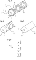
figure 3 , une vue en perspective d'un câble électrique coaxial conforme à l'invention, - les
figures 4 , deux exemples de réalisation distincts d'un diélectrique protégeant une âme centrale conductrice, conformément à l'invention, etet 5 - la
figure 6 , un schéma de principe du procédé de détection conforme à l'invention.
- the
figure 1 , a schematic side view of an aircraft equipped with a leak detection device according to the invention, - the
figure 2 , a detailed side view illustrating more precisely the path of a cable arranged along a pipe, according to the invention, - the
figure 3 , a perspective view of a coaxial electrical cable according to the invention, - the
Figures 4 and 5 two distinct embodiments of a dielectric protecting a central conductive core according to the invention, and - the
figure 6 , a schematic diagram of the detection method according to the invention.
Les éléments présents dans plusieurs figures distinctes sont affectés d'une seule et même référence.The elements present in several separate figures are assigned a single reference.
Comme déjà évoqué, l'invention se rapporte à un dispositif de détection d'une fuite sur une conduite d'un fluide caloporteur équipant un aéronef.As already mentioned, the invention relates to a device for detecting a leak on a pipe of a heat transfer fluid equipping an aircraft.
Tel que représenté à la
A partir de ce groupe de motorisation 20 une conduite 30 permet d'acheminer un fluide caloporteur à l'intérieur du cockpit de l'aéronef 21 vers, par exemple, un échangeur de chaleur 28 permettant de chauffer l'air intérieur du cockpit de l'aéronef 21.From this group of engines 20 a
Un tel dispositif de détection 10 comporte alors un câble électrique 1 s'étendant parallèlement le long et à proximité de la conduite 30. Le câble 1 comporte en outre au niveau d'une première extrémité 25 une bague de connexion 24 permettant de connecter électriquement le câble 1 avec un réflectomètre 27.Such a
Un tel réflectomètre 27 permet alors d'émettre une impulsion de test dans le câble 1, cette impulsion de test se propageant depuis la première extrémité 25 en direction d'une seconde extrémité 26 du câble 1.Such a
L'impulsion de test est ensuite réfléchie dans le câble 1 et retourne en direction de la première extrémité 25 du câble 1.The test pulse is then reflected in the
Lorsqu'une fuite de fluide se produit sur la conduite 30, les caractéristiques électriques du câble 1 agencé à proximité sont modifiées et une discontinuité de son impédance peut être détectée par le dispositif de détection 10.When a leakage of fluid occurs on the
Tel que représenté à la
En dehors de la zone du coude 35 de la conduite 30, le câble 11 peut alors s'étendre parallèlement le long de la conduite 30 ou encore s'étendre sous la forme d'une spirale dont le pas est plus grand que celui de la spirale dans la zone du coude 35.Outside the area of the
Tel que représenté à la
L'âme centrale 2 est recouverte d'un diélectrique 3 isolant de l'électricité et formé dans un matériau spécifique se transformant à une température supérieure à 300°C. Ainsi, tant que la température environnant le câble 1 est inférieure à 300°C, le diélectrique reste à un état solide et les caractéristiques électriques du câble 1, telles que notamment son impédance, restent stables dans le temps.The
A partir d'une température de seuil supérieure à 300°C, typiquement par exemple à 325°C, le matériau du diélectrique peut changer d'état en passant de l'état solide à un état liquide ou visqueux pouvant alors fluer entre les interstices d'une tresse de blindage 4 ajourée recouvrant partiellement une face 8 cylindrique externe du diélectrique 3.From a threshold temperature greater than 300 ° C., typically for example at 325 ° C., the material of the dielectric can change state by passing from the solid state to a liquid state or viscous which can then flow between the interstices of a screened
Une telle tresse de blindage 4 peut alors comporter une pluralité d'ouvertures 7 et recouvrir le diélectrique 3 avec un taux de recouvrement compris entre 30 et 50%. En effet, un tel taux de recouvrement garantit à la fois une bonne tenue mécanique du câble 1 lors de son utilisation sur un aéronef notamment et une bonne réactivité pour transmettre presque instantanément une variation de température du milieu environnant le câble 1.Such a shielding
Telle que représentée, la tresse de blindage 4 peut comporter six fuseaux 6 de trois brins 5, ces fuseaux 6 étant tressés entre eux autour de la face 8 du diélectrique 3 pour former les ouvertures 7 laissant visible la face 8 du diélectrique 3.As shown, the shielding
A titre de variante, les trois brins d'un même fuseau peuvent être eux-mêmes tressés pour un meilleur comportement mécanique à la surface 8 du câble 1.As a variant, the three strands of one and the same spindle can themselves be braided for better mechanical behavior on the
Tel que représenté aux
En effet tel que représenté à la
Selon un deuxième exemple de réalisation tel que représenté à la
Telle que représentée à la
En outre, un tel procédé de détection 31 comporte :
- une étape d'émission 32 lors de laquelle est émise une impulsion de test dans le câble 1.
- une étape de réflexion 33 lors de laquelle est réfléchie au moins partiellement l'impulsion de test
par ledit câble 1, puis - une étape d'analyse 34 lors de laquelle on analyse l'impulsion réfléchie, pour identifier une discontinuité d'impédance dans le câble 1 et déterminer la position dans le câble 1 de cette discontinuité d'impédance.
- an
emission step 32 during which a test pulse is transmitted in thecable 1. - a
reflection step 33 during which the test pulse is reflected at least partially by saidcable 1, then - an
analysis step 34 during which the reflected pulse is analyzed, to identify an impedance discontinuity in thecable 1 and determine the position in thecable 1 of this impedance discontinuity.
L'étape d'émission 32 est réalisée au moyen du réflectomètre temporel 27 comportant un générateur d'impulsions.The
L'étape de réflexion 33 est quant à elle opérée par le câble 1 qui permet de générer une impulsion réfléchie à partir de l'onde de test.The
Enfin l'étape d'analyse 34 est réalisée par le réflectomètre 27 comportant un module d'analyse qui peut par exemple identifier une discontinuité d'impédance obtenue par une transformation du matériau formant le diélectrique 3 du câble 1. Une telle transformation du matériau se produisant à une température supérieure à 300°C correspondant à une fuite de fluide s'échappant de la conduite 30.Finally, the
Naturellement, la présente invention est sujette à de nombreuses variations quant à sa mise en oeuvre. Bien que plusieurs modes de réalisation aient été décrits, on comprend bien qu'il n'est pas concevable d'identifier de manière exhaustive tous les modes possibles. Il est bien sûr envisageable de remplacer un moyen décrit par un moyen équivalent sans sortir du cadre de la présente invention.Naturally, the present invention is subject to many variations as to its implementation. Although several embodiments have been described, it is easy to understand it is inconceivable to exhaustively identify all possible modes. It is of course conceivable to replace a means described by equivalent means without departing from the scope of the present invention.
Claims (15)
caractérisé en ce que ledit diélectrique (3) est formé dans un matériau apte à se transformer à une température supérieure à 300°C et ladite tresse de blindage (4) comporte un taux de recouvrement compris entre 30 et 50%, ledit diélectrique (3) comporte une épaisseur comprise entre 0,01 et 2 mm pour ajuster une rapidité de détection de la température du milieu environnant à proximité du câble électrique coaxial (1, 11).Coaxial electric cable (1, 11) comprising an electrically conducting central core (2), an electrically insulating dielectric (3) covering said central core (2) and a conductive shielding braid (4) of the electricity covering said dielectric (3),
characterized in that said dielectric (3) is formed of a material capable of being transformed at a temperature greater than 300 ° C and said shielding braid (4) has a degree of overlap of between 30 and 50%, said dielectric (3 ) has a thickness of between 0.01 and 2 mm to adjust a speed of detection of the temperature of the surrounding medium near the coaxial electrical cable (1, 11).
caractérisé en ce que ledit matériau formant ledit diélectrique (3) est du Polytétrafluoroéthylène (PTFE).Cable according to claim 1,
characterized in that said material forming said dielectric (3) is polytetrafluoroethylene (PTFE).
caractérisé en ce que ledit diélectrique (3) est non-poreux et la tresse de blindage (4) est ajourée au niveau de croissements entre ses brins formant une couche poreuse permettant, en cas de fuite de fluide, une transmission rapide de la chaleur du fluide au diélectrique (3).Cable according to any one of claims 1 to 2,
characterized in that said dielectric (3) is non-porous and the shielding braid (4) is perforated at the level of crossings between its strands forming a porous layer which, in the event of leakage of fluid, rapidly transmits the heat of the fluid to the dielectric (3).
caractérisé en ce que ledit diélectrique (3) est formé par un ruban (23) enroulé autour de ladite âme centrale (2).Cable according to any one of claims 1 to 3,
characterized in that said dielectric (3) is formed by a ribbon (23) wound around said central core (2).
caractérisé en ce que ladite tresse de blindage (4) comporte une pluralité de brins (5) tressés entre eux, chaque brin (5) étant formé par un fil de cuivre étamé.Cable according to any one of claims 1 to 5,
characterized in that said shielding braid (4) comprises a plurality of strands (5) braided together, each strand (5) being formed by a tinned copper wire.
caractérisé en ce que ladite tresse de blindage (4) comporte x fuseaux (6) tressés entre eux composés chacun de y brins (5), le nombre x de fuseaux (6) étant compris entre 6 et 10 fuseaux et le nombre y de brins (5) de chaque fuseau (6) étant compris entre 3 et 10 brins (5).Cable according to any one of claims 1 to 6,
characterized in that said shielding braid (4) comprises x spindles (6) braided together each composed of y-strands (5), the number x of spindles (6) being between 6 and 10 spindles and the number y of strands (5) each spindle (6) being between 3 and 10 strands (5).
caractérisé en ce que ladite tresse de blindage (4) comporte une pluralité de brins (5) tressés entre eux, chaque brin (5) comportant un diamètre compris entre 0,05 et 0,25 mm.Cable according to any one of claims 1 to 7,
characterized in that said shielding braid (4) comprises a plurality of strands (5) braided together, each strand (5) having a diameter of between 0.05 and 0.25 mm.
caractérisé en ce que ledit dispositif de détection (10) comporte au moins un câble (1, 11) selon l'une quelconque des revendications 1 à 8, ledit câble (1, 11) comportant une bague de connexion (24) agencée au niveau d'une première extrémité (25) dudit câble (1, 11), ladite bague de connexion (24) permettant de connecter électriquement ledit réflectomètre temporel (27) avec ledit câble (1, 11) pour émettre une impulsion de test dans ledit câble (1, 11) et analyser une impulsion réfléchie par ledit câble (1, 11), ledit câble (1, 11) s'étendant le long et à proximité de ladite conduite (30) de fluide et comportant une seconde extrémité libre (26).Detection device (10) for detecting fluid leakage along a fluid line (30), said fluid line (30) for circulating heat transfer fluid on an aircraft (21), said detection device (10) having at least one temporal reflectometer (27),
characterized in that said detection device (10) comprises at least one cable (1, 11) according to any one of claims 1 to 8, said cable (1, 11) having a connecting ring (24) arranged at the level of a first end (25) of said cable (1, 11), said connecting ring (24) for electrically connecting said time domain reflectometer (27) with said cable (1, 11) for transmitting a test pulse in said cable (1, 11) and analyzing a pulse reflected by said cable (1, 11), said cable (1, 11) extending along and in proximity to said fluid conduit (30) and having a second free end (26).
caractérisé en ce que ledit câble (1) s'étend parallèlement par rapport à ladite conduite (30) de fluide.Detection device according to claim 9,
characterized in that said cable (1) extends parallel to said fluid conduit (30).
caractérisé en ce que ledit câble (11) s'étend en formant une spirale autour de ladite conduite (30) de fluide.Detection device according to claim 9,
characterized in that said cable (11) extends spirally around said fluid conduit (30).
caractérisé en ce que ledit procédé de détection (31) comporte :
characterized in that said detection method (31) comprises:
caractérisé en ce que ladite discontinuité d'impédance est obtenue par une transformation du matériau formant le diélectrique (3) dudit câble (1, 11), ladite transformation du matériau se produisant à une température supérieure à 300°C.Process according to claim 12,
characterized in that said impedance discontinuity is obtained by a transformation of the material forming the dielectric (3) of said cable (1, 11), said material transformation occurring at a temperature above 300 ° C.
Applications Claiming Priority (1)
| Application Number | Priority Date | Filing Date | Title |
|---|---|---|---|
| FR1502455A FR3044160B1 (en) | 2015-11-24 | 2015-11-24 | COAXIAL ELECTRICAL CABLE, DETECTION DEVICE EQUIPPED WITH SUCH A CABLE FOR DETECTING A FLUID LEAK HAVING A PIPE AND DETECTION METHOD THEREOF |
Publications (2)
| Publication Number | Publication Date |
|---|---|
| EP3173761A1 true EP3173761A1 (en) | 2017-05-31 |
| EP3173761B1 EP3173761B1 (en) | 2021-01-06 |
Family
ID=55411439
Family Applications (1)
| Application Number | Title | Priority Date | Filing Date |
|---|---|---|---|
| EP16197758.2A Active EP3173761B1 (en) | 2015-11-24 | 2016-11-08 | Coaxial electrical cable, detection device provided with such a cable for detecting a fluid leak from a pipe and associated detection method |
Country Status (2)
| Country | Link |
|---|---|
| EP (1) | EP3173761B1 (en) |
| FR (1) | FR3044160B1 (en) |
Cited By (1)
| Publication number | Priority date | Publication date | Assignee | Title |
|---|---|---|---|---|
| CN110987314A (en) * | 2019-12-09 | 2020-04-10 | 珠海大横琴科技发展有限公司 | Water leakage detection line and water leakage detection system using same |
Citations (7)
| Publication number | Priority date | Publication date | Assignee | Title |
|---|---|---|---|---|
| US4877923A (en) | 1988-08-01 | 1989-10-31 | W. L. Gore & Associates, Inc. | Sensors for detecting and locating liquid leaks |
| US4910998A (en) * | 1987-05-01 | 1990-03-27 | Andrew Corporation | Fluid detection system and method having a coaxial cable with solid, stranded dielectric elements |
| US4965412A (en) | 1989-04-06 | 1990-10-23 | W. L. Gore & Associates, Inc. | Coaxial electrical cable construction |
| EP0544367A1 (en) | 1991-11-27 | 1993-06-02 | Thermocoax | Capacitive sensor having a conductive front face forming a capacitor/armature, and a shielded coaxial cable with a mineral-based insulation |
| WO1993025883A1 (en) * | 1992-06-04 | 1993-12-23 | Midwesco, Inc. | Corrosion resistant cable |
| US20050159915A1 (en) | 2003-12-22 | 2005-07-21 | Oliver Schaumann | Method and device for temperature monitoring along a measuring line |
| US20060020415A1 (en) | 2004-07-23 | 2006-01-26 | Hardwicke Canan U | Sensor and method for making same |
Family Cites Families (1)
| Publication number | Priority date | Publication date | Assignee | Title |
|---|---|---|---|---|
| DE1134532B (en) * | 1959-09-04 | 1962-08-09 | Felten & Guilleaume Carlswerk | Electrical temperature monitoring device, in particular for monitoring the temperature of electrical power and high voltage cables |
-
2015
- 2015-11-24 FR FR1502455A patent/FR3044160B1/en active Active
-
2016
- 2016-11-08 EP EP16197758.2A patent/EP3173761B1/en active Active
Patent Citations (7)
| Publication number | Priority date | Publication date | Assignee | Title |
|---|---|---|---|---|
| US4910998A (en) * | 1987-05-01 | 1990-03-27 | Andrew Corporation | Fluid detection system and method having a coaxial cable with solid, stranded dielectric elements |
| US4877923A (en) | 1988-08-01 | 1989-10-31 | W. L. Gore & Associates, Inc. | Sensors for detecting and locating liquid leaks |
| US4965412A (en) | 1989-04-06 | 1990-10-23 | W. L. Gore & Associates, Inc. | Coaxial electrical cable construction |
| EP0544367A1 (en) | 1991-11-27 | 1993-06-02 | Thermocoax | Capacitive sensor having a conductive front face forming a capacitor/armature, and a shielded coaxial cable with a mineral-based insulation |
| WO1993025883A1 (en) * | 1992-06-04 | 1993-12-23 | Midwesco, Inc. | Corrosion resistant cable |
| US20050159915A1 (en) | 2003-12-22 | 2005-07-21 | Oliver Schaumann | Method and device for temperature monitoring along a measuring line |
| US20060020415A1 (en) | 2004-07-23 | 2006-01-26 | Hardwicke Canan U | Sensor and method for making same |
Cited By (2)
| Publication number | Priority date | Publication date | Assignee | Title |
|---|---|---|---|---|
| CN110987314A (en) * | 2019-12-09 | 2020-04-10 | 珠海大横琴科技发展有限公司 | Water leakage detection line and water leakage detection system using same |
| CN110987314B (en) * | 2019-12-09 | 2020-08-28 | 珠海大横琴科技发展有限公司 | Water leakage detection line and water leakage detection system using same |
Also Published As
| Publication number | Publication date |
|---|---|
| FR3044160B1 (en) | 2018-10-26 |
| EP3173761B1 (en) | 2021-01-06 |
| FR3044160A1 (en) | 2017-05-26 |
Similar Documents
| Publication | Publication Date | Title |
|---|---|---|
| EP1989525B1 (en) | Fault detection system | |
| EP2795281A1 (en) | Method for monitoring the integrity of a flexible line extending through a fluid exploitation facility, and associated flexible line, kit and production process | |
| EP2814041B1 (en) | System for monitoring the wear of an electric cable | |
| EP3066443B1 (en) | Inflatable detecting element, modular detection cable and detection system for detecting leaks of nonconductive liquid | |
| EP2994965B1 (en) | Protective sheath for an electrical harness in order to prevent the deterioration of same | |
| EP2410533B1 (en) | Watertight electrical connection for rotating machine | |
| FR2864687A1 (en) | CURRENT TRANSFORMERS FOR DETECTING PARTIAL DISCHARGES ON CABLES AND WIRES IN AIRCRAFT | |
| EP3227651B1 (en) | Method and device for detecting hot points in a facility, especially for detecting leaks in air ducts | |
| EP3173761B1 (en) | Coaxial electrical cable, detection device provided with such a cable for detecting a fluid leak from a pipe and associated detection method | |
| US20170004902A1 (en) | Induction cable, coupling device, and method for producing an induction cable | |
| CN113237899A (en) | Cable joint operation state detection system and method for enameling lead of cable joint | |
| WO2020253085A1 (en) | Connection method for ybco superconducting material-based superconducting cable | |
| FR2978006A1 (en) | Section of fluid transport pipe for e.g. land transportation of hydrocarbons, has electrical heating system that comprises connecting units to perform electrical connection and linking together electric wires of each of groups | |
| WO2015097278A1 (en) | Method for monitoring the integrity of a flexible tubular pipe | |
| EP0100694A1 (en) | Insulated cable for conveying electrical energy, especially at a high voltage, and device for detecting faults in such a cable | |
| FR3061556B1 (en) | METHOD FOR CONTROLLING AN UNDERWATER DRIVE AND DEVICE FOR IMPLEMENTING IT | |
| FR2691203A1 (en) | Deep drilling auxiliary tube - has jointless core tube of fluoro resin covered by spirally-wound metal cables including a conductor to detect damage | |
| FR3075959A1 (en) | SYSTEM FOR DETECTING THE LEAKAGE OF AN ELECTRICITY CONDUCTIVE FLUID FROM AN ENVELOPE | |
| FR3011670A1 (en) | ELECTRIC HARNESS WITH LOW LINEAR CAPACITY | |
| WO2022229562A1 (en) | Method for discriminant monitoring of a composite multi-material assembly | |
| FR3127576A1 (en) | PROCEDURE FOR MONITORING A PART BY ELECTRICAL REFLECTOMETRY | |
| EP0463599B1 (en) | Apparatus to detect intrusion on a cable link | |
| FR3137760A1 (en) | Device for acoustic detection of an electric arc | |
| FR2680417A1 (en) | Method and device for measuring and adjusting the spatial distribution of electric charges in an insulated electrical cable | |
| CN111256866A (en) | Recoverable temperature sensing cable |
Legal Events
| Date | Code | Title | Description |
|---|---|---|---|
| PUAI | Public reference made under article 153(3) epc to a published international application that has entered the european phase |
Free format text: ORIGINAL CODE: 0009012 |
|
| STAA | Information on the status of an ep patent application or granted ep patent |
Free format text: STATUS: THE APPLICATION HAS BEEN PUBLISHED |
|
| AK | Designated contracting states |
Kind code of ref document: A1 Designated state(s): AL AT BE BG CH CY CZ DE DK EE ES FI FR GB GR HR HU IE IS IT LI LT LU LV MC MK MT NL NO PL PT RO RS SE SI SK SM TR |
|
| AX | Request for extension of the european patent |
Extension state: BA ME |
|
| STAA | Information on the status of an ep patent application or granted ep patent |
Free format text: STATUS: REQUEST FOR EXAMINATION WAS MADE |
|
| 17P | Request for examination filed |
Effective date: 20170612 |
|
| RBV | Designated contracting states (corrected) |
Designated state(s): AL AT BE BG CH CY CZ DE DK EE ES FI FR GB GR HR HU IE IS IT LI LT LU LV MC MK MT NL NO PL PT RO RS SE SI SK SM TR |
|
| STAA | Information on the status of an ep patent application or granted ep patent |
Free format text: STATUS: EXAMINATION IS IN PROGRESS |
|
| 17Q | First examination report despatched |
Effective date: 20190618 |
|
| GRAP | Despatch of communication of intention to grant a patent |
Free format text: ORIGINAL CODE: EPIDOSNIGR1 |
|
| STAA | Information on the status of an ep patent application or granted ep patent |
Free format text: STATUS: GRANT OF PATENT IS INTENDED |
|
| RIC1 | Information provided on ipc code assigned before grant |
Ipc: G01M 3/16 20060101ALI20201002BHEP Ipc: G01M 3/18 20060101AFI20201002BHEP Ipc: G01K 7/34 20060101ALI20201002BHEP Ipc: H01B 7/32 20060101ALN20201002BHEP |
|
| INTG | Intention to grant announced |
Effective date: 20201020 |
|
| GRAS | Grant fee paid |
Free format text: ORIGINAL CODE: EPIDOSNIGR3 |
|
| GRAA | (expected) grant |
Free format text: ORIGINAL CODE: 0009210 |
|
| STAA | Information on the status of an ep patent application or granted ep patent |
Free format text: STATUS: THE PATENT HAS BEEN GRANTED |
|
| AK | Designated contracting states |
Kind code of ref document: B1 Designated state(s): AL AT BE BG CH CY CZ DE DK EE ES FI FR GB GR HR HU IE IS IT LI LT LU LV MC MK MT NL NO PL PT RO RS SE SI SK SM TR |
|
| REG | Reference to a national code |
Ref country code: GB Ref legal event code: FG4D Free format text: NOT ENGLISH |
|
| REG | Reference to a national code |
Ref country code: AT Ref legal event code: REF Ref document number: 1352885 Country of ref document: AT Kind code of ref document: T Effective date: 20210115 Ref country code: CH Ref legal event code: EP |
|
| REG | Reference to a national code |
Ref country code: DE Ref legal event code: R096 Ref document number: 602016050920 Country of ref document: DE |
|
| REG | Reference to a national code |
Ref country code: IE Ref legal event code: FG4D Free format text: LANGUAGE OF EP DOCUMENT: FRENCH |
|
| REG | Reference to a national code |
Ref country code: NL Ref legal event code: MP Effective date: 20210106 |
|
| REG | Reference to a national code |
Ref country code: AT Ref legal event code: MK05 Ref document number: 1352885 Country of ref document: AT Kind code of ref document: T Effective date: 20210106 |
|
| REG | Reference to a national code |
Ref country code: LT Ref legal event code: MG9D |
|
| PG25 | Lapsed in a contracting state [announced via postgrant information from national office to epo] |
Ref country code: HR Free format text: LAPSE BECAUSE OF FAILURE TO SUBMIT A TRANSLATION OF THE DESCRIPTION OR TO PAY THE FEE WITHIN THE PRESCRIBED TIME-LIMIT Effective date: 20210106 Ref country code: FI Free format text: LAPSE BECAUSE OF FAILURE TO SUBMIT A TRANSLATION OF THE DESCRIPTION OR TO PAY THE FEE WITHIN THE PRESCRIBED TIME-LIMIT Effective date: 20210106 Ref country code: GR Free format text: LAPSE BECAUSE OF FAILURE TO SUBMIT A TRANSLATION OF THE DESCRIPTION OR TO PAY THE FEE WITHIN THE PRESCRIBED TIME-LIMIT Effective date: 20210407 Ref country code: NO Free format text: LAPSE BECAUSE OF FAILURE TO SUBMIT A TRANSLATION OF THE DESCRIPTION OR TO PAY THE FEE WITHIN THE PRESCRIBED TIME-LIMIT Effective date: 20210406 Ref country code: PT Free format text: LAPSE BECAUSE OF FAILURE TO SUBMIT A TRANSLATION OF THE DESCRIPTION OR TO PAY THE FEE WITHIN THE PRESCRIBED TIME-LIMIT Effective date: 20210506 Ref country code: BG Free format text: LAPSE BECAUSE OF FAILURE TO SUBMIT A TRANSLATION OF THE DESCRIPTION OR TO PAY THE FEE WITHIN THE PRESCRIBED TIME-LIMIT Effective date: 20210406 Ref country code: NL Free format text: LAPSE BECAUSE OF FAILURE TO SUBMIT A TRANSLATION OF THE DESCRIPTION OR TO PAY THE FEE WITHIN THE PRESCRIBED TIME-LIMIT Effective date: 20210106 Ref country code: LT Free format text: LAPSE BECAUSE OF FAILURE TO SUBMIT A TRANSLATION OF THE DESCRIPTION OR TO PAY THE FEE WITHIN THE PRESCRIBED TIME-LIMIT Effective date: 20210106 |
|
| PG25 | Lapsed in a contracting state [announced via postgrant information from national office to epo] |
Ref country code: RS Free format text: LAPSE BECAUSE OF FAILURE TO SUBMIT A TRANSLATION OF THE DESCRIPTION OR TO PAY THE FEE WITHIN THE PRESCRIBED TIME-LIMIT Effective date: 20210106 Ref country code: PL Free format text: LAPSE BECAUSE OF FAILURE TO SUBMIT A TRANSLATION OF THE DESCRIPTION OR TO PAY THE FEE WITHIN THE PRESCRIBED TIME-LIMIT Effective date: 20210106 Ref country code: LV Free format text: LAPSE BECAUSE OF FAILURE TO SUBMIT A TRANSLATION OF THE DESCRIPTION OR TO PAY THE FEE WITHIN THE PRESCRIBED TIME-LIMIT Effective date: 20210106 Ref country code: AT Free format text: LAPSE BECAUSE OF FAILURE TO SUBMIT A TRANSLATION OF THE DESCRIPTION OR TO PAY THE FEE WITHIN THE PRESCRIBED TIME-LIMIT Effective date: 20210106 Ref country code: SE Free format text: LAPSE BECAUSE OF FAILURE TO SUBMIT A TRANSLATION OF THE DESCRIPTION OR TO PAY THE FEE WITHIN THE PRESCRIBED TIME-LIMIT Effective date: 20210106 |
|
| PG25 | Lapsed in a contracting state [announced via postgrant information from national office to epo] |
Ref country code: IS Free format text: LAPSE BECAUSE OF FAILURE TO SUBMIT A TRANSLATION OF THE DESCRIPTION OR TO PAY THE FEE WITHIN THE PRESCRIBED TIME-LIMIT Effective date: 20210506 |
|
| REG | Reference to a national code |
Ref country code: DE Ref legal event code: R097 Ref document number: 602016050920 Country of ref document: DE |
|
| PG25 | Lapsed in a contracting state [announced via postgrant information from national office to epo] |
Ref country code: CZ Free format text: LAPSE BECAUSE OF FAILURE TO SUBMIT A TRANSLATION OF THE DESCRIPTION OR TO PAY THE FEE WITHIN THE PRESCRIBED TIME-LIMIT Effective date: 20210106 Ref country code: EE Free format text: LAPSE BECAUSE OF FAILURE TO SUBMIT A TRANSLATION OF THE DESCRIPTION OR TO PAY THE FEE WITHIN THE PRESCRIBED TIME-LIMIT Effective date: 20210106 Ref country code: SM Free format text: LAPSE BECAUSE OF FAILURE TO SUBMIT A TRANSLATION OF THE DESCRIPTION OR TO PAY THE FEE WITHIN THE PRESCRIBED TIME-LIMIT Effective date: 20210106 |
|
| PLBE | No opposition filed within time limit |
Free format text: ORIGINAL CODE: 0009261 |
|
| STAA | Information on the status of an ep patent application or granted ep patent |
Free format text: STATUS: NO OPPOSITION FILED WITHIN TIME LIMIT |
|
| PG25 | Lapsed in a contracting state [announced via postgrant information from national office to epo] |
Ref country code: DK Free format text: LAPSE BECAUSE OF FAILURE TO SUBMIT A TRANSLATION OF THE DESCRIPTION OR TO PAY THE FEE WITHIN THE PRESCRIBED TIME-LIMIT Effective date: 20210106 Ref country code: SK Free format text: LAPSE BECAUSE OF FAILURE TO SUBMIT A TRANSLATION OF THE DESCRIPTION OR TO PAY THE FEE WITHIN THE PRESCRIBED TIME-LIMIT Effective date: 20210106 Ref country code: RO Free format text: LAPSE BECAUSE OF FAILURE TO SUBMIT A TRANSLATION OF THE DESCRIPTION OR TO PAY THE FEE WITHIN THE PRESCRIBED TIME-LIMIT Effective date: 20210106 |
|
| 26N | No opposition filed |
Effective date: 20211007 |
|
| PG25 | Lapsed in a contracting state [announced via postgrant information from national office to epo] |
Ref country code: AL Free format text: LAPSE BECAUSE OF FAILURE TO SUBMIT A TRANSLATION OF THE DESCRIPTION OR TO PAY THE FEE WITHIN THE PRESCRIBED TIME-LIMIT Effective date: 20210106 Ref country code: ES Free format text: LAPSE BECAUSE OF FAILURE TO SUBMIT A TRANSLATION OF THE DESCRIPTION OR TO PAY THE FEE WITHIN THE PRESCRIBED TIME-LIMIT Effective date: 20210106 |
|
| PG25 | Lapsed in a contracting state [announced via postgrant information from national office to epo] |
Ref country code: SI Free format text: LAPSE BECAUSE OF FAILURE TO SUBMIT A TRANSLATION OF THE DESCRIPTION OR TO PAY THE FEE WITHIN THE PRESCRIBED TIME-LIMIT Effective date: 20210106 |
|
| PG25 | Lapsed in a contracting state [announced via postgrant information from national office to epo] |
Ref country code: IS Free format text: LAPSE BECAUSE OF FAILURE TO SUBMIT A TRANSLATION OF THE DESCRIPTION OR TO PAY THE FEE WITHIN THE PRESCRIBED TIME-LIMIT Effective date: 20210506 |
|
| REG | Reference to a national code |
Ref country code: DE Ref legal event code: R119 Ref document number: 602016050920 Country of ref document: DE |
|
| PG25 | Lapsed in a contracting state [announced via postgrant information from national office to epo] |
Ref country code: MC Free format text: LAPSE BECAUSE OF FAILURE TO SUBMIT A TRANSLATION OF THE DESCRIPTION OR TO PAY THE FEE WITHIN THE PRESCRIBED TIME-LIMIT Effective date: 20210106 |
|
| REG | Reference to a national code |
Ref country code: CH Ref legal event code: PL |
|
| PG25 | Lapsed in a contracting state [announced via postgrant information from national office to epo] |
Ref country code: LU Free format text: LAPSE BECAUSE OF NON-PAYMENT OF DUE FEES Effective date: 20211108 Ref country code: BE Free format text: LAPSE BECAUSE OF NON-PAYMENT OF DUE FEES Effective date: 20211130 |
|
| REG | Reference to a national code |
Ref country code: BE Ref legal event code: MM Effective date: 20211130 |
|
| PG25 | Lapsed in a contracting state [announced via postgrant information from national office to epo] |
Ref country code: LI Free format text: LAPSE BECAUSE OF NON-PAYMENT OF DUE FEES Effective date: 20211130 Ref country code: CH Free format text: LAPSE BECAUSE OF NON-PAYMENT OF DUE FEES Effective date: 20211130 |
|
| PG25 | Lapsed in a contracting state [announced via postgrant information from national office to epo] |
Ref country code: IE Free format text: LAPSE BECAUSE OF NON-PAYMENT OF DUE FEES Effective date: 20211108 Ref country code: DE Free format text: LAPSE BECAUSE OF NON-PAYMENT OF DUE FEES Effective date: 20220601 |
|
| PG25 | Lapsed in a contracting state [announced via postgrant information from national office to epo] |
Ref country code: HU Free format text: LAPSE BECAUSE OF FAILURE TO SUBMIT A TRANSLATION OF THE DESCRIPTION OR TO PAY THE FEE WITHIN THE PRESCRIBED TIME-LIMIT; INVALID AB INITIO Effective date: 20161108 |
|
| PG25 | Lapsed in a contracting state [announced via postgrant information from national office to epo] |
Ref country code: CY Free format text: LAPSE BECAUSE OF FAILURE TO SUBMIT A TRANSLATION OF THE DESCRIPTION OR TO PAY THE FEE WITHIN THE PRESCRIBED TIME-LIMIT Effective date: 20210106 |
|
| P01 | Opt-out of the competence of the unified patent court (upc) registered |
Effective date: 20230530 |
|
| PGFP | Annual fee paid to national office [announced via postgrant information from national office to epo] |
Ref country code: GB Payment date: 20231123 Year of fee payment: 8 |
|
| PGFP | Annual fee paid to national office [announced via postgrant information from national office to epo] |
Ref country code: IT Payment date: 20231124 Year of fee payment: 8 Ref country code: FR Payment date: 20231120 Year of fee payment: 8 |