EP3193280A1 - Medical imaging device and method of operating the same - Google Patents
Medical imaging device and method of operating the same Download PDFInfo
- Publication number
- EP3193280A1 EP3193280A1 EP16195200.7A EP16195200A EP3193280A1 EP 3193280 A1 EP3193280 A1 EP 3193280A1 EP 16195200 A EP16195200 A EP 16195200A EP 3193280 A1 EP3193280 A1 EP 3193280A1
- Authority
- EP
- European Patent Office
- Prior art keywords
- medical
- images
- imaging device
- boundary
- medical image
- Prior art date
- Legal status (The legal status is an assumption and is not a legal conclusion. Google has not performed a legal analysis and makes no representation as to the accuracy of the status listed.)
- Pending
Links
Images


Classifications
-
- G—PHYSICS
- G06—COMPUTING; CALCULATING OR COUNTING
- G06V—IMAGE OR VIDEO RECOGNITION OR UNDERSTANDING
- G06V10/00—Arrangements for image or video recognition or understanding
- G06V10/40—Extraction of image or video features
- G06V10/46—Descriptors for shape, contour or point-related descriptors, e.g. scale invariant feature transform [SIFT] or bags of words [BoW]; Salient regional features
-
- G—PHYSICS
- G06—COMPUTING; CALCULATING OR COUNTING
- G06F—ELECTRIC DIGITAL DATA PROCESSING
- G06F3/00—Input arrangements for transferring data to be processed into a form capable of being handled by the computer; Output arrangements for transferring data from processing unit to output unit, e.g. interface arrangements
- G06F3/01—Input arrangements or combined input and output arrangements for interaction between user and computer
- G06F3/048—Interaction techniques based on graphical user interfaces [GUI]
- G06F3/0484—Interaction techniques based on graphical user interfaces [GUI] for the control of specific functions or operations, e.g. selecting or manipulating an object, an image or a displayed text element, setting a parameter value or selecting a range
- G06F3/04842—Selection of displayed objects or displayed text elements
-
- G—PHYSICS
- G06—COMPUTING; CALCULATING OR COUNTING
- G06T—IMAGE DATA PROCESSING OR GENERATION, IN GENERAL
- G06T7/00—Image analysis
- G06T7/0002—Inspection of images, e.g. flaw detection
- G06T7/0012—Biomedical image inspection
-
- G—PHYSICS
- G06—COMPUTING; CALCULATING OR COUNTING
- G06T—IMAGE DATA PROCESSING OR GENERATION, IN GENERAL
- G06T7/00—Image analysis
- G06T7/10—Segmentation; Edge detection
- G06T7/11—Region-based segmentation
-
- G—PHYSICS
- G06—COMPUTING; CALCULATING OR COUNTING
- G06V—IMAGE OR VIDEO RECOGNITION OR UNDERSTANDING
- G06V10/00—Arrangements for image or video recognition or understanding
- G06V10/70—Arrangements for image or video recognition or understanding using pattern recognition or machine learning
- G06V10/74—Image or video pattern matching; Proximity measures in feature spaces
- G06V10/75—Organisation of the matching processes, e.g. simultaneous or sequential comparisons of image or video features; Coarse-fine approaches, e.g. multi-scale approaches; using context analysis; Selection of dictionaries
- G06V10/752—Contour matching
-
- G—PHYSICS
- G06—COMPUTING; CALCULATING OR COUNTING
- G06T—IMAGE DATA PROCESSING OR GENERATION, IN GENERAL
- G06T2200/00—Indexing scheme for image data processing or generation, in general
- G06T2200/24—Indexing scheme for image data processing or generation, in general involving graphical user interfaces [GUIs]
-
- G—PHYSICS
- G06—COMPUTING; CALCULATING OR COUNTING
- G06T—IMAGE DATA PROCESSING OR GENERATION, IN GENERAL
- G06T2207/00—Indexing scheme for image analysis or image enhancement
- G06T2207/30—Subject of image; Context of image processing
- G06T2207/30004—Biomedical image processing
- G06T2207/30096—Tumor; Lesion
-
- G—PHYSICS
- G06—COMPUTING; CALCULATING OR COUNTING
- G06V—IMAGE OR VIDEO RECOGNITION OR UNDERSTANDING
- G06V2201/00—Indexing scheme relating to image or video recognition or understanding
- G06V2201/03—Recognition of patterns in medical or anatomical images
Definitions
- One or more embodiments relate to medical imaging devices and methods of operating the same, and more particularly, to medical imaging devices generating diagnostic information about an object by using medical images having different modalities from each other and methods of operating the same.
- Imaging devices for obtaining information by imaging tissues of a human body are used in many medical areas for the early diagnosis of various diseases or surgical operations related to such diseases.
- Some examples of such medical imaging devices are ultrasonic diagnosing devices, computed tomography (CT) devices, and magnetic resonance imaging (MRI) devices.
- CT computed tomography
- MRI magnetic resonance imaging
- Medical imaging devices may extract a boundary of an object from an obtained medical image by using a computer aided detection (CAD) system and may provide diagnostic information about the object based on the extracted boundary.
- CAD computer aided detection
- an image matching method is a processing method of adjusting separate images and displaying the images in a coordinate system.
- a user can see how images obtained by different measurement methods are matched with each other by the image matching method.
- an ultrasound image, a CT image, and a magnetic resonance (MR) image may be matched with each other.
- One or more embodiments include medical imaging devices extracting a boundary of an object (for example, a lesion) based on medical images having different modalities from each other, and generating diagnostic information by analyzing each of the medical images based on the extracted boundary, and methods of operating the same.
- a boundary of an object for example, a lesion
- One or more embodiments include medical imaging devices, wherein when an object is selected in one of medical images having different modalities from each other, remaining medical images also extract a boundary of the object, and when the boundary of the object is corrected in one of the medical images having different modalities from each other, remaining medical images also correct the boundary of the object, and methods of operating the same.
- a medical imaging device includes a display configured to display first and second medical images having different modalities from each other with respect to an object, an image processor configured to match the first and second medical images, configured to extract a second object corresponding to a first object selected in the first medical image from the second medical image, extract first feature information of the first object by analyzing the first medical image, and extract second feature information of the second object by analyzing the second medical image, and a controller configured to generate final diagnostic information based on the first and second feature information, and control the display to display the final diagnostic information.
- a method of operating a medical imaging device includes displaying first and second medical images having different modalities from each other with respect to an object, matching the first and second medical images, extracting a second object corresponding to a first object from the second medical image, wherein the first object is selected from the first medical image, extracting first feature information with respect to the first object by analyzing the first medical image, and further extracting second feature information with respect to the second object by analyzing the second medical image, generating final diagnostic information based on the first and second feature information, and displaying the final diagnostic information.
- an "image” may refer to multi-dimensional data composed of discrete image elements.
- Some examples of such images are medical images (ultrasound images, computed tomography (CT) images, magnetic resonance (MR) images, X-ray images, positron emission tomography (PET) images, PET/CT images, and PET/MR images) of an object obtained by ultrasonic diagnosing devices, CT devices, MRI devices, X-ray devices, and PET device, but the inventive concept is not limited thereto.
- an "object” may be a human, an animal, or a part of a human or animal.
- the object may be an organ (e.g., the liver, heart, womb, brain, breast, or abdomen), a blood vessel, or a combination thereof.
- the object may be a phantom.
- the phantom means a material having a density, an effective atomic number, and a volume that are approximately the same as those of an organism.
- the phantom may be a spherical phantom having properties similar to a human body.
- An ultrasound image may refer to an image obtained by transmitting ultrasound signals generated by a transducer of a probe to an object and receiving echo signals reflected from the object. Furthermore, the ultrasound image may vary.
- the ultrasound image may be at least one of, for example, an amplitude (A) mode image, a brightness (B) mode image, a color (C) mode image, and a Doppler (D) mode image.
- the ultrasound image may be a 2-dimensional (2D) image or a 3-dimensional (3D) image.
- the CT image may refer to a synthesized image of a plurality of X-ray images that are obtained by capturing an object while rotating about at least one axis of the object.
- a magnetic resonance (MR) image may refer to an image of an object obtained based on a nuclear magnetic resonance principle.
- a "user” may be, but is not limited to, a medical expert, for example, a medical doctor, a nurse, a medical laboratory technologist, or a medical imaging expert, or a technician who repairs medical apparatuses.
- FIG. 1 is a block diagram of a medical imaging device 100, according to an embodiment.
- the medical imaging device 100 may include an image processor 110, a controller 120, and a display 130.
- the image processor 110 may match medical images having different modalities from each other with respect to an object.
- the medical images having different modalities from each other may include medical images obtained by separate measurement methods with respect to the object.
- medical images having different modalities from each other may include ultrasound images, X-ray images, CT images, MR images, PET images, PET/CT images, and PET/MR images, but are not limited thereto.
- the image processor 110 may match first and second medical images having different modalities from each other.
- the image processor 110 may extract individual anatomical structures corresponding to an object from the first and second medical images and may match the first and second medical images by using the extracted individual anatomical structures.
- the image processor 110 may extract individual anatomical structures (for example, an inferior vena cava (IVC), a hepatic vein, a hepatic portal vein, etc.) corresponding to the liver from the first and second medical images.
- the image processor 110 may extract individual anatomical structures (for example, a diaphragm, a blood vessel adjacent to abdomen, etc.) corresponding to the abdomen from the first and second medical images.
- the image processor 110 may extract individual anatomical structures (for example, a thyroid, a carotid, a trachea, etc.) corresponding to the thyroid from the first and second medical images.
- the image processor 110 may match the first and second medical images based on a geometric relationship between the extracted individual anatomical structures. For example, the image processor 110 may match the first and second medical images by using positions and directions of the extracted individual anatomical structures.
- the image processor 110 may extract a first object selected from the first medical image, and may extract a second object corresponding to the first object from the second medical image.
- the first and second objects may be an identical anatomical individual.
- the image processor 110 may designate the selected point as a seed point of the first object, and may extract the first object by using a region growing method. For example, the image processor 110 may search points adjacent to the selected point in a preset region based on the selected point, and may include the searched points in a first object region when a difference between a brightness value of the searched points and a reference brightness value is a critical value or less.
- the image processor 110 may detect a point matched with the point selected in the first object from the second medical image, may designate the selected point as a seed point, and may extract the second object by using a region growing method.
- a method of extracting the first and second objects is not limited to the region growing method, and the image processor 110 may extract the first and second objects by using various known methods.
- the image processor 110 may extract first feature information with respect to the first object by analyzing the first medical image, and may further extract second feature information with respect to the second object by analyzing the second medical image.
- the image processor 110 may analyze the first medical image and may obtain information about a shape, a direction, an angle margin, a boundary of a lesion, and calcification of the first object.
- the image processor 110 may analyze the second medical image and may obtain information about a shape, a direction, an angle margin, a boundary of a lesion, and calcification of the second object.
- the image processor 110 may obtain information about an echo pattern and a posterior acoustic feature of the first object or the second object.
- the first and second feature information is not limited thereto and the image processor 110 may include various pieces of information for diagnosing the first and second objects.
- the controller 120 may control general operations of the medical imaging device 100 and a flow of signals between internal components of the medical imaging device 100.
- the controller 120 may include a memory storing a program or data for performing a prescribed function, and a processor processing the program or the data.
- the controller 120 may generate final diagnostic information based on the first and second feature information. For example, the controller 120 may determine whether an object is benign or malignant, based on features included in the first and second feature information.
- the display 130 may display a plurality of medical images having different modalities from each other.
- the display 130 may display not only a medical image, but also various pieces of information processed by the medical imaging device 100 on a screen image via a graphical user interface (GUI).
- GUI graphical user interface
- the medical imaging device 100 may include two or more displays 130 according to embodiments.
- the display 130 may display the first and second medical images having different modalities from each other, and may further display boundaries of the first and second medical images, respectively.
- the display 130 may display the first feature information extracted from the first medical image and the second feature information extracted from the second medical image, and may further display the final diagnostic information generated based on the first and second feature information.
- FIG. 2 is a block diagram illustrating a configuration of a medical imaging device 200 according to an embodiment.
- the medical imaging device 200 may include an image processor 210, a controller 220, a display 230, a data acquisition unit 240, an input interface 250, a communicator 260, and a storage 270, according to an embodiment.
- the image processor 110 of FIG. 1 may correspond to the image processor 210 of FIG. 2
- the controller 120 of FIG. 1 may correspond to the controller 220 of FIG. 2
- the display 130 of FIG. 1 may correspond to the display 230 of FIG. 2 .
- like reference numerals in FIG. 1 denote like elements, and a duplicate description will be omitted for simplicity.
- the data acquisition unit 240 may obtain medical image data of an object.
- the medical image data may include ultrasound data, CT data, or MR data, but is not limited thereto.
- the data acquisition unit 240 may transmit an ultrasound signal to an object and may receive an echo signal reflected from the object. The data acquisition unit 240 may process the received echo signal and may generate ultrasound data with respect to the object. Furthermore, the data acquisition unit 240 may transmit a radio frequency (RF) signal to an object and may receive an MR signal emitted from the object. The data acquisition unit 240 may process the received MR signal and may generate MR data with respect to the object. Furthermore, the data acquisition unit 240 may transmit an X-ray signal to an object and may sense the X-ray signal received from the object. The data acquisition unit 240 may process the sensed X-ray signal and may generate CT data with respect to the object.
- RF radio frequency
- the data acquisition unit 240 may receive medical image data generated in external medical devices such as ultrasonic diagnosing devices, MRI devices, and CT devices, without directly generating medical image data such as ultrasound data, MR data, or CT data by receiving an ultrasound signal, an MR signal, or an X-ray signal.
- external medical devices such as ultrasonic diagnosing devices, MRI devices, and CT devices
- medical image data such as ultrasound data, MR data, or CT data by receiving an ultrasound signal, an MR signal, or an X-ray signal.
- the medical image data may be 2D data or 3D volume data.
- 2D data indicates a section of an object
- 3D volume data indicates data reconfigured in a 3D form, in which many pieces of section data of an object are stored.
- the image processor 210 may generate a plurality of medical images based on the medical image data. For example, the image processor 210, when ultrasound data is obtained, may generate an ultrasound image based on the ultrasound data, and when MR data is obtained, may generate an MR image based on the MR data. Furthermore, the image processor 210, when CT data is obtained, may generate a CT image based on the CT data. Furthermore, the image processor 210 may generate X-ray images, PET images, PET/CT images, and PET/MR images, but the inventive concept is not limited thereto.
- a plurality of medical images may be respective medical images corresponding to various sections of an object.
- the image processor 210 may match medical images having different modalities from each other.
- the medical images having different modalities from each other may be images generated by the image processor 210 by using medical image data, but are not limited thereto.
- the medical images having different modalities may be medical images received from an external device through the communicator 260, or medical images loaded from the storage 270.
- the image processor 210 may analyze each of the matched medical images having different modalities from each other, and may extract feature information of an object.
- the display 230 may display a medical image generated in the image processor 210, a medical image received via the communicator 260, and a medical image loaded in the storage 270. Furthermore, the display 230 may display various pieces of information processed in the medical imaging device 200. In addition, the medical imaging device 200 may include two or more displays 230 according to embodiments. Furthermore, if the display 230 includes a touch screen with a touchpad, the display 230 may also be used as an input device as well as an output device.
- the display 230 may include at least one of a liquid crystal display (LCD), a thin film transistor-LCD (TFT-LCD), an organic light-emitting diode (OLED) display, a flexible display, a 3D display, and an electrophoretic display.
- LCD liquid crystal display
- TFT-LCD thin film transistor-LCD
- OLED organic light-emitting diode
- the controller 220 may control general operations of the medical imaging device 200 and a flow of signals between internal components of the medical imaging device 200.
- the controller 220 may include a memory storing a program or data for performing a prescribed function, and a processor processing the program or the data. Furthermore, the controller 220 may receive a control signal from the input interface 250 or an external device, and may control operations of the medical imaging device 200.
- the communicator 260 is connected to the network 30 by wire or wirelessly to communicate with a server 31 or an external device 32.
- the external device 32 may include, for example, a medical device and a portable device.
- the portable device may include a communication terminal, a tablet personal computer (PC), a medical terminal, and a wearable device.
- the communicator 260 may include one or more components for communication with servers or external devices.
- the communicator 260 may include a local area communicator, a wired communicator, and a mobile communicator.
- the local area communicator refers to a module for local area communication within a prescribed distance.
- Examples of local area communication techniques may include, but are not limited to, wireless LAN, Wi-Fi, Bluetooth, ZigBee, Wi-Fi Direct (WFD), ultra wideband (UWB), infrared data association (IrDA), Bluetooth low energy (BLE), and near field communication (NFC).
- the wired communicator refers to a module for communication using electric signals or optical signals.
- Examples of wired communication techniques according to an embodiment may include communication via a twisted pair cable, a coaxial cable, an optical fiber cable, and an Ethernet cable.
- the mobile communicator transmits or receives wireless signals to or from at least one selected from a base station, an external terminal, and a server on a mobile communication network.
- the wireless signal may be a voice call signal, a video call signal, or data in any one of various formats according to transmission and reception of a text/multimedia message.
- the communicator 260 may transmit or receive a control signal and data with the server 31 or the external device 32 via a medical image information system (PACS).
- PACS medical image information system
- the communicator 260 may receive a control signal from the server 31 or the external device 32, and the controller 220 may generally control operations of the medical imaging device 200 according to the received control signal. For example, the controller 220 may control obtaining of medical image data; processing, displaying and storing of medical image; and transmitting or receiving of data.
- the communicator 260 may transmit or receive data related to diagnosis of an object or medical image data via the server 31 or the external device 32.
- the storage 270 may store a variety of data or programs for operating and controlling the medical imaging device 200. Furthermore, the storage 270 may store various pieces of information processed in the medical imaging device 200. For example, the storage 270 may store medical data related to object diagnosis such as medical image data and medical images to be input or output, and may further store an algorithm or a program performed in the medical imaging device 200.
- the storage 270 may be any of various storage media, e.g., a flash memory, a hard disk drive, EEPROM, etc. Furthermore, the medical imaging device 200 may utilize web storage or a cloud server that performs the storage function of the storage 270 online.
- the input interface 250 may receive data for controlling the medical imaging device 200 from a user.
- the input interface 250 may include a button, a keypad, a mouse, a touch pad, a touch screen, a track ball, a jog switch, and a knop, but is not limited thereto.
- the input interface 250 includes a touch screen
- a medical image in a prescribed mode and a control panel for the medical image may be displayed on the touch screen.
- the medical imaging device 200 may sense a touch gesture of a user corresponding to a medical image via the touch screen.
- the medical imaging device 200 may include some buttons that are frequently used by a user among buttons that are included in a control panel of a general medical imaging device, and provide the remaining buttons in the form of a graphical user interface (GUI) via a touch screen.
- GUI graphical user interface
- All or some of the image processor 210, the controller 220, the display 230, the data acquisition unit 240, the input interface 250, the communicator 260, and the storage 270 may be implemented as software modules. However, embodiments of the present invention are not limited thereto, and some of the components stated above may be implemented as hardware modules.
- FIG. 3 is a view illustrating a plurality of medical images that are displayed on a display 120 according to an embodiment.
- the medical imaging device 100 may display medical images having different modalities from each other with respect to an object on the display 120.
- the medical images according to the embodiment may include ultrasound images, X-ray images, CT images, MR images, PET images, PET/CT images, and PET/MR images, but are not limited thereto.
- the medical imaging device 100 may display first to third medical images 310 to 330, wherein the first medical image 310 may be an ultrasound image, the second medical image 320 may be a CT image, and the third medical image 330 may be an MR image, but the inventive concept is not limited thereto.
- the medical images according to the embodiment may be matched images with each other.
- the first medical image 310 and the second medical image 320 may be matched with each other
- the first medical image 310 and the third medical image 330 may be matched with each other
- the second medical image 320 and the third medical image 330 may be matched with each other.
- the medical imaging device 100 may receive a user input 340 selecting a first object in the first medical image 310.
- the medical imaging device 100 may receive an input selecting a point included in the first object, and an input selecting a prescribed region including the first object.
- the medical imaging device 100 may extract a boundary 315 of the first object. For example, when a point included in the first object is selected, the medical imaging device 100 may designate the selected point as a seed point of the first object, and may extract the boundary 315 of the first object by using a region growing method. In addition, it is possible to segment the first object in the first medical image 310.
- the medical imaging device 100 may extract objects corresponding to the first object from the second and third medical images 320 and 330.
- the medical imaging device 100 may detect a point matched with the point selected in the first medical image 310 from the second medical image 320, may designate the selected point as a seed point, and may extract a boundary 325 of a second object corresponding to the first object by using a region growing method. Furthermore, the medical imaging device 100 may detect a point matched with the point selected in the first medical image 310 from the third medical image 330, may designate the selected point as a seed point, and may extract a boundary 335 of a third object corresponding to the first object by using a region growing method.
- each modality displays individual anatomical structures in different ways even though the first to third objects are the same individual anatomical structures, and thus, boundaries of objects respectively extracted from the first to third medical images 310 to 330 may be different from each other.
- an ultrasound image as performing rapid inspection in real time without using radiation harmful to human body compared to medical images having another modalities, may be advantageous for monitoring a treatment progress, and may display thyroid, breast, scrotum, musculoskeletal system, or heart as well as organs such as liver, gall bladder, pancreas, spleen, and kidney, or pelvic cavity organs such as bladder, womb, ovary, and prostate gland.
- a CT image compared to medical images having other modalities, may display a bone, a calcificated lesion, cerebral hemorrhage, lung or heart, and organs in which peristalsis occurs.
- an MR image compared to medical images having other modalities, may display a muscle, a ligament, brain-nervous system, a tumor, and a soft tissue well.
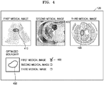
- FIG. 4 is a view illustrating an example of correcting a result of extracting a boundary of an object, in medical images having different modalities from each other, according to an embodiment.
- the medical imaging device 100 may display medical images having different modalities from each other, and may display the result of extracting a boundary of an object on each of the medical images.
- the medical imaging device 100 may segment the object in each of the medical images and may extract a boundary of the object. Furthermore, the medical imaging device 100 may display a boundary 410 of the first object on the first medical image, a boundary 420 of the second object on the second medical image, and a boundary 430 of the third object on the third medical image, according to a result of the boundary extraction.
- the medical imaging device 100 may correct boundaries of objects displayed on remaining medical images.
- the medical imaging device 100 may receive an input selecting the first medical image from among the plurality of medical images (or, an input selecting the boundary 410 of the first object displayed on the first medical image).
- the medical imaging device 100 may correct the boundary 420 of the second object and the boundary 430 of the third object based on the boundary 410 of the first object.
- the medical imaging device 100 may correct the boundary 420 of the second object to correspond to the boundary 410 of the first object, by using a matching result of the first and second medical images.
- the medical imaging device 100 may correct the boundary 430 of the third object to correspond to the boundary 410 of the first object, by using a matching result of the first and third medical images, but the inventive concept is not limited thereto.
- the medical imaging device 100 may generate an optimized boundary of an object.
- the medical imaging device 100 may generate an optimized boundary of an object by using various calculation values (for example, average values) based on the boundary 410 of the first object, the boundary 420 of the second object, and the boundary 430 of the third object.
- the medical imaging device 100 may display the optimized boundary and may correct at least one from among the boundary 410 of the first object, the boundary 420 of the second object, and the boundary 430 of the third object, to the optimized boundary. For example, as illustrated in FIG. 4 , when receiving a user input selecting a check box 460 corresponding to each medical image displayed on a display 120, the medical imaging device 100 may control a boundary displayed on a medical image corresponding to the selected check box to be corrected to an optimized boundary.
- FIG. 5 is a view illustrating an example of correcting a result of extracting a boundary of an object, in medical images having different modalities from each other, according to an embodiment.
- the medical imaging device 100 may display medical images having different modalities from each other, and may display the result of extracting a boundary of an object on each of the medical images. For example, a boundary 410 of a first object may be displayed on a first medical image, a boundary 420 of a second object on a second medical image, and a boundary 430 of a third object on a third medical image.
- the medical imaging device 100 may receive an input correcting any one of the boundaries of the objects respectively displayed on the plurality of medical images. For example, when receiving an input selecting the boundary 420 of the second object displayed on the second medical image, the medical imaging device 100 may display candidate boundaries corresponding to the second object.
- the candidate boundaries may include first to third candidate boundaries 510 to 530, wherein the first to third candidate boundaries 510 to 530 may be boundaries extracted by using respective algorithms.
- the medical imaging device 100 may receive an input selecting one of the candidate boundaries, and may correct the boundary 420 of the second object displayed on the second medical image to the selected candidate boundary.
- the medical imaging device 100 may also correct the boundary 410 of the first object and the boundary 430 of the third object based on the corrected boundary 420 of the second object. For example, the medical imaging device 100 may correct the boundary 410 of the first object to correspond to the corrected boundary 420 of the second object, by using a matching result of the first and second medical images. Furthermore, the medical imaging device 100 may correct the boundary 430 of the third object to correspond to the corrected boundary 420 of the second object, by using a matching result of the second and third medical images, but the inventive concept is not limited thereto.
- FIG. 6 is a view illustrating an example of correcting a result of extracting a boundary of an object, in medical images having different modalities from each other, according to an embodiment.
- the medical imaging device 100 may display medical images having different modalities from each other, and may display the result of extracting a boundary of an object on each of the medical images. For example, a boundary 410 of a first object may be displayed on a first medical image, a boundary 420 of a second object on a second medical image, and a boundary 430 of a third object on a third medical image.
- the medical imaging device 100 may receive an input correcting any one of the boundaries of the objects respectively displayed on the plurality of medical images. For example, when receiving an input selecting the boundary 420 of the second object displayed on the second medical image, the medical imaging device 100 may display a window 610 capable of correct the boundary 420 of the second object. For example, as illustrated in FIG. 6 , the window 610 may display an enlarged boundary 620 of the second object, and may further display a plurality of dots 630 forming the boundary 620 of the second object.
- the medical imaging device 100 may change a position of at least one of the plurality of dots 630 by receiving a user input, may correct the boundary 620 to pass through a dot 635 having the changed position, or may add a dot and correct the boundary 620 to pass through the added dot. Furthermore, the medical imaging device 100 may display the boundary corrected in the window 610 by applying to the boundary 420 of the second object displayed on the second medical image.
- the medical imaging device 100 may also correct the boundary 410 of the first object and the boundary 430 of the third object based on a second boundary corrected in the first and third medical images. For example, the medical imaging device 100 may correct the boundary 410 of the first object to correspond to the corrected boundary 420 of the second object, by using a matching result of the first and second medical images. Furthermore, the medical imaging device 100 may correct the boundary 430 of the third object to correspond to the corrected boundary 420 of the second object, by using a matching result of the second and third medical images, but the inventive concept is not limited thereto.
- FIGS. 7A and 7B are views illustrating a plurality of medical images displaying final diagnostic information, which is obtained by analyzing the plurality of medical images, according to an embodiment.
- the medical imaging device 100 may analyze each of the plurality of medical images based on a boundary of an object displayed on each of the plurality of medical images, and may extract feature information of each object.
- the feature information may include information about a shape, a direction, an angle margin, a boundary of a lesion, and calcification of each object. Furthermore, the feature information may include information about an echo pattern and a posterior acoustic feature of each object.
- the medical imaging device 100 may analyze a first medical image based on a boundary 410 of a first object displayed on a first medical image, and may extract feature information (first feature information 710) of the first object. Furthermore, the medical imaging device 100 may analyze a second medical image based on a boundary 420 of a second object displayed on a second medical image, and may extract feature information (second feature information 720) of second object. Moreover, the medical imaging device 100 may analyze a third medical image based on a boundary 430 of a third object displayed on a third medical image, and may extract feature information (third feature information 730) of third object.
- the medical imaging device 100 may display the first to third feature information 710 to 730 on a display 120.
- the medical imaging device 100 may generate final diagnostic information of an object based on the first to third feature information 710 to 730.
- the medical imaging device 100 may determine features of an object based on the first to third feature information 710 to 730. Some of features of an object may be shown only in a part of a plurality of medical images. For example, some of features of an object included in the first feature information 710 may not be included in the second feature information 720 or the third feature information 730.
- the medical imaging device 100 may determine features of an object by considering the first to third feature information 710 to 730 overall. Furthermore, the medical imaging device 100 may determine whether the object is benign or malignant, based on the determined features.
- the medical imaging device 100 may display final diagnostic information 750 including the determined feature information of the object and the information (for example, "Possibly Benign") about whether the object is benign or malignant, based on the first to third feature information 710 to 730.
- the medical imaging device 100 may only display the final diagnostic information 750 including the determined feature information of the object and the information about whether the object is benign or malignant based on the first to third feature information 710 to 730, without displaying the first to third feature information 710 to 730.
- FIG. 8 is a flowchart of a method of operating a medical imaging device according to an embodiment.
- the medical imaging device 100 may display first and second medical images having different modalities from each other (S810).
- the first and second medical images may include at least one of ultrasound images, X-ray images, CT images, MR images, PET images, PET/CT images, and PET/MR images.
- the medical imaging device 100 may match the first and second medical images with each other (S820).
- the medical imaging device 100 may extract individual anatomical structures corresponding to an object from the first and second medical images, and may match the first and second medical images based on a geometric relationship between the extracted individual anatomical structures.
- the medical imaging device 100 may extract a first object from the first medical image (S830).
- the medical imaging device 100 may designate the selected point as a seed point of the first object, and may extract the first object by using a region growing method.
- the medical imaging device 100 may search points adjacent to the selected point in a preset region based on the selected point, and may include the searched points in a first object region when a difference between a brightness value of the searched points and a reference brightness value is a critical value or less.
- the medical imaging device 100 may extract a second object corresponding to the first object from the second medical image (S840).
- the medical imaging device 100 may detect a point matched with the point selected in the first object from the second medical image, may designate the selected point as a seed point, and may extract the second object by using a region growing method.
- a method of extracting the first and second objects is not limited to the region growing method, the image processor 110 may extract the first and second objects by using various known methods.
- the medical imaging device 100 may extract first feature information with respect to the first object by analyzing the first medical image, and may extract second feature information with respect to the second object by analyzing the second medical image (S850).
- the medical imaging device 100 may analyze the first medical image and may obtain information about a shape, a direction, an angle margin, a boundary of a lesion, and calcification of the first object. Furthermore, the medical imaging device 100 may analyze the second medical image and may obtain information about a shape, a direction, an angle margin, a boundary of a lesion, and calcification of the second object.
- the medical imaging device 100 may obtain information about an echo pattern and a posterior acoustic feature of the first object or the second object.
- the first and second feature information is not limited thereto and the medical imaging device 100 may include various pieces of information for diagnosing the first and second objects.
- the medical imaging device 100 may generate final diagnostic information based on the first and second feature information, and may display the generated final diagnostic information (S860).
- the medical imaging device 100 may determine features of an object by considering the first and second feature information overall. Furthermore, the medical imaging device 100 may determine whether the object is benign or malignant, based on the determined features.
- the medical imaging device 100 may display final diagnostic information including the determined feature information of the object and the information (for example, "Possibly Benign") about whether the object is benign or malignant.
- the medical imaging device and the method of operating the same according to the embodiments can also be embodied as computer-readable codes on a non-transitory computer-readable recording medium.
- the non-transitory computer-readable recording medium is any data storage device that can store data which can thereafter be read by a computer system. ROM, RAM. Examples of the non-transitory computer-readable recording medium include read-only memory (ROM), random-access memory (RAM), CD-ROMs, magnetic tapes, floppy disks, optical data storage devices, etc.
- the non-transitory computer-readable recording medium can also be distributed over network coupled computer systems so that the computer-readable code is stored and executed in a distributive manner.
- accuracy of diagnostic information of an object may increase as generating the diagnostic information by using medical images having different modalities from each other.
- use convenience of a user may be improved since the user is required to select an object or correct a boundary of the object in only one of medical images having different modalities from each other.
Abstract
Description
- This application claims the benefit of
Korean Patent Application No. 10-2016-0005995, filed on January 18, 2016 - One or more embodiments relate to medical imaging devices and methods of operating the same, and more particularly, to medical imaging devices generating diagnostic information about an object by using medical images having different modalities from each other and methods of operating the same.
- Various imaging devices for obtaining information by imaging tissues of a human body are used in many medical areas for the early diagnosis of various diseases or surgical operations related to such diseases. Some examples of such medical imaging devices are ultrasonic diagnosing devices, computed tomography (CT) devices, and magnetic resonance imaging (MRI) devices. Medical imaging devices may extract a boundary of an object from an obtained medical image by using a computer aided detection (CAD) system and may provide diagnostic information about the object based on the extracted boundary.
- Meanwhile, an image matching method is a processing method of adjusting separate images and displaying the images in a coordinate system. A user can see how images obtained by different measurement methods are matched with each other by the image matching method. For example, an ultrasound image, a CT image, and a magnetic resonance (MR) image may be matched with each other.
- One or more embodiments include medical imaging devices extracting a boundary of an object (for example, a lesion) based on medical images having different modalities from each other, and generating diagnostic information by analyzing each of the medical images based on the extracted boundary, and methods of operating the same.
- One or more embodiments include medical imaging devices, wherein when an object is selected in one of medical images having different modalities from each other, remaining medical images also extract a boundary of the object, and when the boundary of the object is corrected in one of the medical images having different modalities from each other, remaining medical images also correct the boundary of the object, and methods of operating the same.
- Additional aspects will be set forth in part in the description which follows and, in part, will be apparent from the description, or may be learned by practice of the presented embodiments.
- According to one or more embodiments, a medical imaging device includes a display configured to display first and second medical images having different modalities from each other with respect to an object, an image processor configured to match the first and second medical images, configured to extract a second object corresponding to a first object selected in the first medical image from the second medical image, extract first feature information of the first object by analyzing the first medical image, and extract second feature information of the second object by analyzing the second medical image, and a controller configured to generate final diagnostic information based on the first and second feature information, and control the display to display the final diagnostic information.
- According to one or more embodiments, a method of operating a medical imaging device includes displaying first and second medical images having different modalities from each other with respect to an object, matching the first and second medical images, extracting a second object corresponding to a first object from the second medical image, wherein the first object is selected from the first medical image, extracting first feature information with respect to the first object by analyzing the first medical image, and further extracting second feature information with respect to the second object by analyzing the second medical image, generating final diagnostic information based on the first and second feature information, and displaying the final diagnostic information.
- These and/or other aspects will become apparent and more readily appreciated from the following description of the embodiments, taken in conjunction with the accompanying drawings in which:
-
FIG. 1 is a block diagram of a medical imaging device, according to an embodiment; -
FIG. 2 is a block diagram illustrating a configuration of a medical imaging device, according to an embodiment; -
FIG. 3 is a view illustrating a plurality of medical images that are displayed on a display according to an embodiment; -
FIG. 4 is a view illustrating an example of correcting a result of extracting a boundary of an object, in medical images having different modalities from each other, according to an embodiment; -
FIG. 5 is a view illustrating an example of correcting a result of extracting a boundary of an object, in medical images having different modalities from each other, according to an embodiment; -
FIG. 6 is a view illustrating an example of correcting a result of extracting a boundary of an object, in medical images having different modalities from each other, according to an embodiment; -
FIGS. 7A and7B are views illustrating a plurality of medical images displaying final diagnostic information, which is obtained by analyzing the plurality of medical images, according to an embodiment; and -
FIG. 8 is a flowchart of a method of operating a medical imaging device according to an embodiment. - Reference will now be made in detail to embodiments, examples of which are illustrated in the accompanying drawings, wherein like reference numerals refer to like elements throughout. In this regard, the present embodiments may have different forms and should not be construed as being limited to the descriptions set forth herein. Accordingly, the embodiments are merely described below, by referring to the figures, to explain aspects of the present description. Expressions such as "at least one of," when preceding a list of elements, modify the entire list of elements and do not modify the individual elements of the list.
- General and widely used terms have been employed herein, in consideration of functions provided in the disclosure, and may vary according to an intention of one of ordinary skill in the art, a precedent, or emergence of new technologies. Additionally, in some cases, an applicant may arbitrarily select specific terms, in which case, the applicant will provide the meaning of the terms in the description of the embodiments. Accordingly, It will be understood that the terms used herein should be interpreted as having a meaning that is consistent with their meaning in the context of the relevant art and will not be interpreted in an idealized or overly formal sense unless expressly so defined herein.
- Throughout the specification, when a portion "includes" an element, another element may be further included, rather than excluding the existence of the other element, unless otherwise described. In addition, terms such as "... unit", "... module", or the like refer to units that perform at least one function or operation, and the units may be implemented as hardware or software or as a combination of hardware and software.
- Throughout the specification, an "image" may refer to multi-dimensional data composed of discrete image elements. Some examples of such images are medical images (ultrasound images, computed tomography (CT) images, magnetic resonance (MR) images, X-ray images, positron emission tomography (PET) images, PET/CT images, and PET/MR images) of an object obtained by ultrasonic diagnosing devices, CT devices, MRI devices, X-ray devices, and PET device, but the inventive concept is not limited thereto.
- Furthermore, an "object" may be a human, an animal, or a part of a human or animal. For example, the object may be an organ (e.g., the liver, heart, womb, brain, breast, or abdomen), a blood vessel, or a combination thereof. Also, the object may be a phantom. The phantom means a material having a density, an effective atomic number, and a volume that are approximately the same as those of an organism. For example, the phantom may be a spherical phantom having properties similar to a human body.
- An ultrasound image may refer to an image obtained by transmitting ultrasound signals generated by a transducer of a probe to an object and receiving echo signals reflected from the object. Furthermore, the ultrasound image may vary. The ultrasound image may be at least one of, for example, an amplitude (A) mode image, a brightness (B) mode image, a color (C) mode image, and a Doppler (D) mode image. Also, according to an exemplary embodiment, the ultrasound image may be a 2-dimensional (2D) image or a 3-dimensional (3D) image.
- The CT image may refer to a synthesized image of a plurality of X-ray images that are obtained by capturing an object while rotating about at least one axis of the object.
- A magnetic resonance (MR) image may refer to an image of an object obtained based on a nuclear magnetic resonance principle.
- Throughout the specification, a "user" may be, but is not limited to, a medical expert, for example, a medical doctor, a nurse, a medical laboratory technologist, or a medical imaging expert, or a technician who repairs medical apparatuses.
- Below, a detailed description will be given about embodiments of the present inventive concept with reference to attached drawings such that one of an ordinary skill in the art may easily perform the embodiments. In this regard, the present embodiments may have different forms and should not be construed as being limited to the descriptions set forth herein.
-
FIG. 1 is a block diagram of amedical imaging device 100, according to an embodiment. Referring toFIG. 1 , themedical imaging device 100 may include animage processor 110, acontroller 120, and adisplay 130. - According to an embodiment, the
image processor 110 may match medical images having different modalities from each other with respect to an object. The medical images having different modalities from each other may include medical images obtained by separate measurement methods with respect to the object. For example, medical images having different modalities from each other may include ultrasound images, X-ray images, CT images, MR images, PET images, PET/CT images, and PET/MR images, but are not limited thereto. - According to an embodiment, the
image processor 110 may match first and second medical images having different modalities from each other. Theimage processor 110 may extract individual anatomical structures corresponding to an object from the first and second medical images and may match the first and second medical images by using the extracted individual anatomical structures. - For example, when the object is a liver, the
image processor 110 may extract individual anatomical structures (for example, an inferior vena cava (IVC), a hepatic vein, a hepatic portal vein, etc.) corresponding to the liver from the first and second medical images. Furthermore, when the object is an abdomen, theimage processor 110 may extract individual anatomical structures (for example, a diaphragm, a blood vessel adjacent to abdomen, etc.) corresponding to the abdomen from the first and second medical images. Furthermore, when the object is a thyroid, theimage processor 110 may extract individual anatomical structures (for example, a thyroid, a carotid, a trachea, etc.) corresponding to the thyroid from the first and second medical images. - Furthermore, the
image processor 110 may match the first and second medical images based on a geometric relationship between the extracted individual anatomical structures. For example, theimage processor 110 may match the first and second medical images by using positions and directions of the extracted individual anatomical structures. - Furthermore, the
image processor 110 may extract a first object selected from the first medical image, and may extract a second object corresponding to the first object from the second medical image. The first and second objects may be an identical anatomical individual. - When a point is selected in the first medical image, the
image processor 110 may designate the selected point as a seed point of the first object, and may extract the first object by using a region growing method. For example, theimage processor 110 may search points adjacent to the selected point in a preset region based on the selected point, and may include the searched points in a first object region when a difference between a brightness value of the searched points and a reference brightness value is a critical value or less. - Furthermore, the
image processor 110 may detect a point matched with the point selected in the first object from the second medical image, may designate the selected point as a seed point, and may extract the second object by using a region growing method. - However, a method of extracting the first and second objects is not limited to the region growing method, and the
image processor 110 may extract the first and second objects by using various known methods. - The
image processor 110 may extract first feature information with respect to the first object by analyzing the first medical image, and may further extract second feature information with respect to the second object by analyzing the second medical image. For example, theimage processor 110 may analyze the first medical image and may obtain information about a shape, a direction, an angle margin, a boundary of a lesion, and calcification of the first object. Furthermore, theimage processor 110 may analyze the second medical image and may obtain information about a shape, a direction, an angle margin, a boundary of a lesion, and calcification of the second object. - Furthermore, the
image processor 110 may obtain information about an echo pattern and a posterior acoustic feature of the first object or the second object. However, the first and second feature information is not limited thereto and theimage processor 110 may include various pieces of information for diagnosing the first and second objects. - The
controller 120 may control general operations of themedical imaging device 100 and a flow of signals between internal components of themedical imaging device 100. Thecontroller 120 may include a memory storing a program or data for performing a prescribed function, and a processor processing the program or the data. - According to an embodiment, the
controller 120 may generate final diagnostic information based on the first and second feature information. For example, thecontroller 120 may determine whether an object is benign or malignant, based on features included in the first and second feature information. - The
display 130 may display a plurality of medical images having different modalities from each other. Thedisplay 130 may display not only a medical image, but also various pieces of information processed by themedical imaging device 100 on a screen image via a graphical user interface (GUI). In addition, themedical imaging device 100 may include two ormore displays 130 according to embodiments. - According to an embodiment, the
display 130 may display the first and second medical images having different modalities from each other, and may further display boundaries of the first and second medical images, respectively. - Furthermore, according to an embodiment, the
display 130 may display the first feature information extracted from the first medical image and the second feature information extracted from the second medical image, and may further display the final diagnostic information generated based on the first and second feature information. -
FIG. 2 is a block diagram illustrating a configuration of amedical imaging device 200 according to an embodiment. - Referring to
FIG. 2 , themedical imaging device 200 may include animage processor 210, acontroller 220, adisplay 230, adata acquisition unit 240, aninput interface 250, acommunicator 260, and astorage 270, according to an embodiment. - Meanwhile, the
image processor 110 ofFIG. 1 may correspond to theimage processor 210 ofFIG. 2 , thecontroller 120 ofFIG. 1 may correspond to thecontroller 220 ofFIG. 2 , and thedisplay 130 ofFIG. 1 may correspond to thedisplay 230 ofFIG. 2 . InFIG. 2 , like reference numerals inFIG. 1 denote like elements, and a duplicate description will be omitted for simplicity. - According to an embodiment, the
data acquisition unit 240 may obtain medical image data of an object. The medical image data may include ultrasound data, CT data, or MR data, but is not limited thereto. - For example, the
data acquisition unit 240 may transmit an ultrasound signal to an object and may receive an echo signal reflected from the object. Thedata acquisition unit 240 may process the received echo signal and may generate ultrasound data with respect to the object. Furthermore, thedata acquisition unit 240 may transmit a radio frequency (RF) signal to an object and may receive an MR signal emitted from the object. Thedata acquisition unit 240 may process the received MR signal and may generate MR data with respect to the object. Furthermore, thedata acquisition unit 240 may transmit an X-ray signal to an object and may sense the X-ray signal received from the object. Thedata acquisition unit 240 may process the sensed X-ray signal and may generate CT data with respect to the object. - However, the
data acquisition unit 240 may receive medical image data generated in external medical devices such as ultrasonic diagnosing devices, MRI devices, and CT devices, without directly generating medical image data such as ultrasound data, MR data, or CT data by receiving an ultrasound signal, an MR signal, or an X-ray signal. - According to an embodiment, the medical image data may be 2D data or 3D volume data. 2D data indicates a section of an object, and 3D volume data indicates data reconfigured in a 3D form, in which many pieces of section data of an object are stored.
- According to an embodiment, the
image processor 210 may generate a plurality of medical images based on the medical image data. For example, theimage processor 210, when ultrasound data is obtained, may generate an ultrasound image based on the ultrasound data, and when MR data is obtained, may generate an MR image based on the MR data. Furthermore, theimage processor 210, when CT data is obtained, may generate a CT image based on the CT data. Furthermore, theimage processor 210 may generate X-ray images, PET images, PET/CT images, and PET/MR images, but the inventive concept is not limited thereto. - According to an embodiment, a plurality of medical images may be respective medical images corresponding to various sections of an object.
- Meanwhile, the
image processor 210 may match medical images having different modalities from each other. The medical images having different modalities from each other may be images generated by theimage processor 210 by using medical image data, but are not limited thereto. The medical images having different modalities may be medical images received from an external device through thecommunicator 260, or medical images loaded from thestorage 270. Furthermore, theimage processor 210 may analyze each of the matched medical images having different modalities from each other, and may extract feature information of an object. - The
display 230 may display a medical image generated in theimage processor 210, a medical image received via thecommunicator 260, and a medical image loaded in thestorage 270. Furthermore, thedisplay 230 may display various pieces of information processed in themedical imaging device 200. In addition, themedical imaging device 200 may include two ormore displays 230 according to embodiments. Furthermore, if thedisplay 230 includes a touch screen with a touchpad, thedisplay 230 may also be used as an input device as well as an output device. - The
display 230 may include at least one of a liquid crystal display (LCD), a thin film transistor-LCD (TFT-LCD), an organic light-emitting diode (OLED) display, a flexible display, a 3D display, and an electrophoretic display. - The
controller 220 may control general operations of themedical imaging device 200 and a flow of signals between internal components of themedical imaging device 200. Thecontroller 220 may include a memory storing a program or data for performing a prescribed function, and a processor processing the program or the data. Furthermore, thecontroller 220 may receive a control signal from theinput interface 250 or an external device, and may control operations of themedical imaging device 200. - The
communicator 260 is connected to thenetwork 30 by wire or wirelessly to communicate with aserver 31 or anexternal device 32. Theexternal device 32 may include, for example, a medical device and a portable device. Furthermore, the portable device may include a communication terminal, a tablet personal computer (PC), a medical terminal, and a wearable device. - The
communicator 260 may include one or more components for communication with servers or external devices. For example, thecommunicator 260 may include a local area communicator, a wired communicator, and a mobile communicator. - The local area communicator refers to a module for local area communication within a prescribed distance. Examples of local area communication techniques according to an embodiment may include, but are not limited to, wireless LAN, Wi-Fi, Bluetooth, ZigBee, Wi-Fi Direct (WFD), ultra wideband (UWB), infrared data association (IrDA), Bluetooth low energy (BLE), and near field communication (NFC).
- The wired communicator refers to a module for communication using electric signals or optical signals. Examples of wired communication techniques according to an embodiment may include communication via a twisted pair cable, a coaxial cable, an optical fiber cable, and an Ethernet cable.
- The mobile communicator transmits or receives wireless signals to or from at least one selected from a base station, an external terminal, and a server on a mobile communication network. Here, the wireless signal may be a voice call signal, a video call signal, or data in any one of various formats according to transmission and reception of a text/multimedia message.
- The
communicator 260 may transmit or receive a control signal and data with theserver 31 or theexternal device 32 via a medical image information system (PACS). - The
communicator 260 may receive a control signal from theserver 31 or theexternal device 32, and thecontroller 220 may generally control operations of themedical imaging device 200 according to the received control signal. For example, thecontroller 220 may control obtaining of medical image data; processing, displaying and storing of medical image; and transmitting or receiving of data. - Furthermore, the
communicator 260 may transmit or receive data related to diagnosis of an object or medical image data via theserver 31 or theexternal device 32. - The
storage 270 may store a variety of data or programs for operating and controlling themedical imaging device 200. Furthermore, thestorage 270 may store various pieces of information processed in themedical imaging device 200. For example, thestorage 270 may store medical data related to object diagnosis such as medical image data and medical images to be input or output, and may further store an algorithm or a program performed in themedical imaging device 200. - The
storage 270 may be any of various storage media, e.g., a flash memory, a hard disk drive, EEPROM, etc. Furthermore, themedical imaging device 200 may utilize web storage or a cloud server that performs the storage function of thestorage 270 online. - The
input interface 250 may receive data for controlling themedical imaging device 200 from a user. For example, theinput interface 250 may include a button, a keypad, a mouse, a touch pad, a touch screen, a track ball, a jog switch, and a knop, but is not limited thereto. - If the
input interface 250 includes a touch screen, a medical image in a prescribed mode and a control panel for the medical image may be displayed on the touch screen. Furthermore, themedical imaging device 200 may sense a touch gesture of a user corresponding to a medical image via the touch screen. Furthermore, themedical imaging device 200 may include some buttons that are frequently used by a user among buttons that are included in a control panel of a general medical imaging device, and provide the remaining buttons in the form of a graphical user interface (GUI) via a touch screen. - All or some of the
image processor 210, thecontroller 220, thedisplay 230, thedata acquisition unit 240, theinput interface 250, thecommunicator 260, and thestorage 270 may be implemented as software modules. However, embodiments of the present invention are not limited thereto, and some of the components stated above may be implemented as hardware modules. -
FIG. 3 is a view illustrating a plurality of medical images that are displayed on adisplay 120 according to an embodiment. - Referring to
FIG. 3 , according to an embodiment, themedical imaging device 100 may display medical images having different modalities from each other with respect to an object on thedisplay 120. The medical images according to the embodiment may include ultrasound images, X-ray images, CT images, MR images, PET images, PET/CT images, and PET/MR images, but are not limited thereto. - For example, the
medical imaging device 100 may display first to thirdmedical images 310 to 330, wherein the firstmedical image 310 may be an ultrasound image, the secondmedical image 320 may be a CT image, and the thirdmedical image 330 may be an MR image, but the inventive concept is not limited thereto. - Furthermore, the medical images according to the embodiment may be matched images with each other. For example, the first
medical image 310 and the secondmedical image 320 may be matched with each other, the firstmedical image 310 and the thirdmedical image 330 may be matched with each other, and the secondmedical image 320 and the thirdmedical image 330 may be matched with each other. - According to an embodiment, the
medical imaging device 100 may receive auser input 340 selecting a first object in the firstmedical image 310. For example, themedical imaging device 100 may receive an input selecting a point included in the first object, and an input selecting a prescribed region including the first object. - The
medical imaging device 100 may extract aboundary 315 of the first object. For example, when a point included in the first object is selected, themedical imaging device 100 may designate the selected point as a seed point of the first object, and may extract theboundary 315 of the first object by using a region growing method. In addition, it is possible to segment the first object in the firstmedical image 310. - Furthermore, the
medical imaging device 100 may extract objects corresponding to the first object from the second and thirdmedical images - For example, the
medical imaging device 100 may detect a point matched with the point selected in the firstmedical image 310 from the secondmedical image 320, may designate the selected point as a seed point, and may extract aboundary 325 of a second object corresponding to the first object by using a region growing method. Furthermore, themedical imaging device 100 may detect a point matched with the point selected in the firstmedical image 310 from the thirdmedical image 330, may designate the selected point as a seed point, and may extract aboundary 335 of a third object corresponding to the first object by using a region growing method. Here, each modality displays individual anatomical structures in different ways even though the first to third objects are the same individual anatomical structures, and thus, boundaries of objects respectively extracted from the first to thirdmedical images 310 to 330 may be different from each other. - For example, an ultrasound image, as performing rapid inspection in real time without using radiation harmful to human body compared to medical images having another modalities, may be advantageous for monitoring a treatment progress, and may display thyroid, breast, scrotum, musculoskeletal system, or heart as well as organs such as liver, gall bladder, pancreas, spleen, and kidney, or pelvic cavity organs such as bladder, womb, ovary, and prostate gland. Furthermore, a CT image, compared to medical images having other modalities, may display a bone, a calcificated lesion, cerebral hemorrhage, lung or heart, and organs in which peristalsis occurs. Furthermore, an MR image, compared to medical images having other modalities, may display a muscle, a ligament, brain-nervous system, a tumor, and a soft tissue well.
-
FIG. 4 is a view illustrating an example of correcting a result of extracting a boundary of an object, in medical images having different modalities from each other, according to an embodiment. - Referring to
FIG. 4 , according to an embodiment, themedical imaging device 100 may display medical images having different modalities from each other, and may display the result of extracting a boundary of an object on each of the medical images. - For example, as described above in
FIG. 3 , when receiving an input of selecting an object from any one of a plurality of medical images (first to third medical images), themedical imaging device 100 may segment the object in each of the medical images and may extract a boundary of the object. Furthermore, themedical imaging device 100 may display aboundary 410 of the first object on the first medical image, aboundary 420 of the second object on the second medical image, and aboundary 430 of the third object on the third medical image, according to a result of the boundary extraction. - According to an embodiment, the
medical imaging device 100, based on a boundary of an object displayed on any one of a plurality of medical images, may correct boundaries of objects displayed on remaining medical images. - For example, the
medical imaging device 100 may receive an input selecting the first medical image from among the plurality of medical images (or, an input selecting theboundary 410 of the first object displayed on the first medical image). When the first medical image is selected, themedical imaging device 100 may correct theboundary 420 of the second object and theboundary 430 of the third object based on theboundary 410 of the first object. For example, themedical imaging device 100 may correct theboundary 420 of the second object to correspond to theboundary 410 of the first object, by using a matching result of the first and second medical images. Furthermore, themedical imaging device 100 may correct theboundary 430 of the third object to correspond to theboundary 410 of the first object, by using a matching result of the first and third medical images, but the inventive concept is not limited thereto. - Furthermore, according to an embodiment, the
medical imaging device 100, based on boundaries of objects extracted from a plurality of medical images, may generate an optimized boundary of an object. For example, themedical imaging device 100 may generate an optimized boundary of an object by using various calculation values (for example, average values) based on theboundary 410 of the first object, theboundary 420 of the second object, and theboundary 430 of the third object. - The
medical imaging device 100 may display the optimized boundary and may correct at least one from among theboundary 410 of the first object, theboundary 420 of the second object, and theboundary 430 of the third object, to the optimized boundary. For example, as illustrated inFIG. 4 , when receiving a user input selecting acheck box 460 corresponding to each medical image displayed on adisplay 120, themedical imaging device 100 may control a boundary displayed on a medical image corresponding to the selected check box to be corrected to an optimized boundary. -
FIG. 5 is a view illustrating an example of correcting a result of extracting a boundary of an object, in medical images having different modalities from each other, according to an embodiment. - Referring to
FIG. 5 , according to an embodiment, themedical imaging device 100 may display medical images having different modalities from each other, and may display the result of extracting a boundary of an object on each of the medical images. For example, aboundary 410 of a first object may be displayed on a first medical image, aboundary 420 of a second object on a second medical image, and aboundary 430 of a third object on a third medical image. - The
medical imaging device 100 may receive an input correcting any one of the boundaries of the objects respectively displayed on the plurality of medical images. For example, when receiving an input selecting theboundary 420 of the second object displayed on the second medical image, themedical imaging device 100 may display candidate boundaries corresponding to the second object. - For example, as illustrated in
FIG. 5 , the candidate boundaries may include first tothird candidate boundaries 510 to 530, wherein the first tothird candidate boundaries 510 to 530 may be boundaries extracted by using respective algorithms. Themedical imaging device 100 may receive an input selecting one of the candidate boundaries, and may correct theboundary 420 of the second object displayed on the second medical image to the selected candidate boundary. - Furthermore, when the
boundary 420 of the second object on the second medical image is corrected, themedical imaging device 100 may also correct theboundary 410 of the first object and theboundary 430 of the third object based on the correctedboundary 420 of the second object. For example, themedical imaging device 100 may correct theboundary 410 of the first object to correspond to the correctedboundary 420 of the second object, by using a matching result of the first and second medical images. Furthermore, themedical imaging device 100 may correct theboundary 430 of the third object to correspond to the correctedboundary 420 of the second object, by using a matching result of the second and third medical images, but the inventive concept is not limited thereto. -
FIG. 6 is a view illustrating an example of correcting a result of extracting a boundary of an object, in medical images having different modalities from each other, according to an embodiment. - Referring to
FIG. 6 , according to an embodiment, themedical imaging device 100 may display medical images having different modalities from each other, and may display the result of extracting a boundary of an object on each of the medical images. For example, aboundary 410 of a first object may be displayed on a first medical image, aboundary 420 of a second object on a second medical image, and aboundary 430 of a third object on a third medical image. - The
medical imaging device 100 may receive an input correcting any one of the boundaries of the objects respectively displayed on the plurality of medical images. For example, when receiving an input selecting theboundary 420 of the second object displayed on the second medical image, themedical imaging device 100 may display awindow 610 capable of correct theboundary 420 of the second object. For example, as illustrated inFIG. 6 , thewindow 610 may display anenlarged boundary 620 of the second object, and may further display a plurality ofdots 630 forming theboundary 620 of the second object. - The
medical imaging device 100 may change a position of at least one of the plurality ofdots 630 by receiving a user input, may correct theboundary 620 to pass through adot 635 having the changed position, or may add a dot and correct theboundary 620 to pass through the added dot. Furthermore, themedical imaging device 100 may display the boundary corrected in thewindow 610 by applying to theboundary 420 of the second object displayed on the second medical image. - Furthermore, when the
boundary 420 of the second object on the second medical image is corrected, themedical imaging device 100 may also correct theboundary 410 of the first object and theboundary 430 of the third object based on a second boundary corrected in the first and third medical images. For example, themedical imaging device 100 may correct theboundary 410 of the first object to correspond to the correctedboundary 420 of the second object, by using a matching result of the first and second medical images. Furthermore, themedical imaging device 100 may correct theboundary 430 of the third object to correspond to the correctedboundary 420 of the second object, by using a matching result of the second and third medical images, but the inventive concept is not limited thereto. -
FIGS. 7A and7B are views illustrating a plurality of medical images displaying final diagnostic information, which is obtained by analyzing the plurality of medical images, according to an embodiment. - The
medical imaging device 100 may analyze each of the plurality of medical images based on a boundary of an object displayed on each of the plurality of medical images, and may extract feature information of each object. - According to an embodiment, the feature information may include information about a shape, a direction, an angle margin, a boundary of a lesion, and calcification of each object. Furthermore, the feature information may include information about an echo pattern and a posterior acoustic feature of each object.
- For example, as illustrated in
FIG. 7A , themedical imaging device 100 may analyze a first medical image based on aboundary 410 of a first object displayed on a first medical image, and may extract feature information (first feature information 710) of the first object. Furthermore, themedical imaging device 100 may analyze a second medical image based on aboundary 420 of a second object displayed on a second medical image, and may extract feature information (second feature information 720) of second object. Moreover, themedical imaging device 100 may analyze a third medical image based on aboundary 430 of a third object displayed on a third medical image, and may extract feature information (third feature information 730) of third object. - As illustrated in
FIG. 7A , themedical imaging device 100 may display the first tothird feature information 710 to 730 on adisplay 120. - According to an embodiment, the
medical imaging device 100 may generate final diagnostic information of an object based on the first tothird feature information 710 to 730. Themedical imaging device 100 may determine features of an object based on the first tothird feature information 710 to 730. Some of features of an object may be shown only in a part of a plurality of medical images. For example, some of features of an object included in thefirst feature information 710 may not be included in thesecond feature information 720 or thethird feature information 730. Themedical imaging device 100 may determine features of an object by considering the first tothird feature information 710 to 730 overall. Furthermore, themedical imaging device 100 may determine whether the object is benign or malignant, based on the determined features. - According to an embodiment, as illustrated in
FIGS. 7A and7B , themedical imaging device 100 may display finaldiagnostic information 750 including the determined feature information of the object and the information (for example, "Possibly Benign") about whether the object is benign or malignant, based on the first tothird feature information 710 to 730. - Meanwhile, referring to
FIG. 7B , themedical imaging device 100 may only display the finaldiagnostic information 750 including the determined feature information of the object and the information about whether the object is benign or malignant based on the first tothird feature information 710 to 730, without displaying the first tothird feature information 710 to 730. -
FIG. 8 is a flowchart of a method of operating a medical imaging device according to an embodiment. - Referring to
FIG. 8 , according to an embodiment, themedical imaging device 100 may display first and second medical images having different modalities from each other (S810). - For example, the first and second medical images may include at least one of ultrasound images, X-ray images, CT images, MR images, PET images, PET/CT images, and PET/MR images.
- The
medical imaging device 100 may match the first and second medical images with each other (S820). - For example, the
medical imaging device 100 may extract individual anatomical structures corresponding to an object from the first and second medical images, and may match the first and second medical images based on a geometric relationship between the extracted individual anatomical structures. - The
medical imaging device 100 may extract a first object from the first medical image (S830). - For example, when a point is selected in the first medical image, the
medical imaging device 100 may designate the selected point as a seed point of the first object, and may extract the first object by using a region growing method. Themedical imaging device 100 may search points adjacent to the selected point in a preset region based on the selected point, and may include the searched points in a first object region when a difference between a brightness value of the searched points and a reference brightness value is a critical value or less. - The
medical imaging device 100 may extract a second object corresponding to the first object from the second medical image (S840). - For example, the
medical imaging device 100 may detect a point matched with the point selected in the first object from the second medical image, may designate the selected point as a seed point, and may extract the second object by using a region growing method. - However, a method of extracting the first and second objects is not limited to the region growing method, the
image processor 110 may extract the first and second objects by using various known methods. - The
medical imaging device 100 may extract first feature information with respect to the first object by analyzing the first medical image, and may extract second feature information with respect to the second object by analyzing the second medical image (S850). - For example, the
medical imaging device 100 may analyze the first medical image and may obtain information about a shape, a direction, an angle margin, a boundary of a lesion, and calcification of the first object. Furthermore, themedical imaging device 100 may analyze the second medical image and may obtain information about a shape, a direction, an angle margin, a boundary of a lesion, and calcification of the second object. - Furthermore, the
medical imaging device 100 may obtain information about an echo pattern and a posterior acoustic feature of the first object or the second object. However, the first and second feature information is not limited thereto and themedical imaging device 100 may include various pieces of information for diagnosing the first and second objects. - The
medical imaging device 100 may generate final diagnostic information based on the first and second feature information, and may display the generated final diagnostic information (S860). - The
medical imaging device 100 may determine features of an object by considering the first and second feature information overall. Furthermore, themedical imaging device 100 may determine whether the object is benign or malignant, based on the determined features. - According to an embodiment, the
medical imaging device 100 may display final diagnostic information including the determined feature information of the object and the information (for example, "Possibly Benign") about whether the object is benign or malignant. - The medical imaging device and the method of operating the same according to the embodiments can also be embodied as computer-readable codes on a non-transitory computer-readable recording medium. The non-transitory computer-readable recording medium is any data storage device that can store data which can thereafter be read by a computer system. ROM, RAM. Examples of the non-transitory computer-readable recording medium include read-only memory (ROM), random-access memory (RAM), CD-ROMs, magnetic tapes, floppy disks, optical data storage devices, etc. The non-transitory computer-readable recording medium can also be distributed over network coupled computer systems so that the computer-readable code is stored and executed in a distributive manner.
- According to an embodiment, accuracy of diagnostic information of an object may increase as generating the diagnostic information by using medical images having different modalities from each other.
- According to an embodiment, use convenience of a user may be improved since the user is required to select an object or correct a boundary of the object in only one of medical images having different modalities from each other.
- It should be understood that embodiments described herein should be considered in a descriptive sense only and not for purposes of limitation. Descriptions of features or aspects within each embodiment should typically be considered as available for other similar features or aspects in other embodiments.
- While one or more embodiments have been described with reference to the figures, it will be understood by those of ordinary skill in the art that various changes in form and details may be made therein without departing from the spirit and scope of the inventive concept as defined by the following claims.
Claims (15)
- A medical imaging device comprising:a display configured to display first and second medical images having different modalities from each other with respect to an object;an image processor configured to match the first and second medical images, configured to extract a second object corresponding to a first object selected in the first medical image from the second medical image, extract first feature information of the first object by analyzing the first medical image, and extract second feature information of the second object by analyzing the second medical image; anda controller configured to generate final diagnostic information based on the first and second feature information, and control the display to display the final diagnostic information.
- The medical imaging device of claim 1, further comprising:a data acquisition unit configured to acquire first and second medical image data having different modalities from each other, whereinthe image processor is further configured to generate the first medical image based on the first medical image data, and generate the second medical image based on the second medical image data.
- The medical imaging device of claim 1, further comprising:an input interface configured to receive a user input selecting the first object in the first medical image.
- The medical imaging device of claim 1, wherein
the image processor is further configured to extract a first boundary of the first object and a second boundary of the second object, and
the controller is further configured to control the display to display the first and second boundaries. - The medical imaging device of claim 4, wherein
the image processor is further configured to extract the first and second feature information based on a third boundary calculated based on the first and second boundaries. - The medical imaging device of claim 5, wherein
the controller is further configured to control the display to display the third boundary. - The medical imaging device of claim 1, wherein
the first feature information comprises at least one of information about a shape, a direction, an angle margin, a boundary of a lesion, calcification, an echo pattern, and a posterior acoustic feature of the first object, and
the second feature information comprises at least one of information about a shape, a direction, an angle margin, a boundary of a lesion, calcification, an echo pattern, and a posterior acoustic feature of the second object. - The medical imaging device of claim 1, wherein
the controller is further configured to determine whether the first object is benign or malignant based on the first and second feature information, and
the final diagnostic information comprises information of whether the first object is benign or malignant. - The medical imaging device of claim 1, wherein
the first and second medical images comprises at least one of ultrasound images, X-ray images, computed tomography (CT) images, magnetic resonance (MR) images, positron emission tomography (PET) images, PET/CT images, and PET/MR images. - A method of operating a medical imaging device, the method comprising:displaying first and second medical images having different modalities from each other with respect to an object;matching the first and second medical images;extracting a second object corresponding to a first object from the second medical image, wherein the first object is selected from the first medical image;extracting first feature information with respect to the first object by analyzing the first medical image, and further extracting second feature information with respect to the second object by analyzing the second medical image;generating final diagnostic information based on the first and second feature information; anddisplaying the final diagnostic information.
- The method of claim 10, further comprising:acquiring first and second medical image data having different modalities from each other; andgenerating the first medical image based on the first medical image data, and further generating the second medical image based on the second medical image data.
- The method of claim 10, further comprising:receiving a user input selecting the first object in the first medical image.
- The method of claim 10, further comprising:extracting a first boundary of the first object and a second boundary of the second object; anddisplaying the first and second boundaries.
- The method of claim 13, further comprising:calculating a third boundary based on the first and second boundaries, andthe extracting of the first and second feature information comprises extracting the first and second feature information based on the third boundary.
- The method of claim 10, wherein
the generating of the final diagnostic information comprises:determining whether the first object is benign or malignant based on the first and second feature information, whereinthe final diagnostic information comprises:information of whether the first object is benign or malignant.
Applications Claiming Priority (1)
| Application Number | Priority Date | Filing Date | Title |
|---|---|---|---|
| KR1020160005995A KR102439769B1 (en) | 2016-01-18 | 2016-01-18 | Medical imaging apparatus and operating method for the same |
Publications (1)
| Publication Number | Publication Date |
|---|---|
| EP3193280A1 true EP3193280A1 (en) | 2017-07-19 |
Family
ID=57206047
Family Applications (1)
| Application Number | Title | Priority Date | Filing Date |
|---|---|---|---|
| EP16195200.7A Pending EP3193280A1 (en) | 2016-01-18 | 2016-10-24 | Medical imaging device and method of operating the same |
Country Status (3)
| Country | Link |
|---|---|
| US (1) | US10290097B2 (en) |
| EP (1) | EP3193280A1 (en) |
| KR (1) | KR102439769B1 (en) |
Families Citing this family (7)
| Publication number | Priority date | Publication date | Assignee | Title |
|---|---|---|---|---|
| WO2019166447A1 (en) * | 2018-03-02 | 2019-09-06 | Koninklijke Philips N.V. | Image registration qualification |
| WO2020012884A1 (en) * | 2018-07-13 | 2020-01-16 | 古野電気株式会社 | Ultrasound imaging device, ultrasound imaging system, ultrasound imaging method and ultrasound imaging program |
| KR20200109093A (en) * | 2019-03-12 | 2020-09-22 | 삼성메디슨 주식회사 | Apparatus and method for displaying ultrasound image and computer program product |
| KR102375910B1 (en) * | 2020-03-02 | 2022-03-16 | 연세대학교 산학협력단 | Ultrasound Image-guided Method and Apparatus |
| CN111553919B (en) * | 2020-05-12 | 2022-12-30 | 上海深至信息科技有限公司 | Thyroid nodule analysis system based on elastic ultrasonic imaging |
| KR102375786B1 (en) * | 2020-09-14 | 2022-03-17 | 주식회사 뷰노 | Method for detecting abnormal findings and generating interpretation text of medical image |
| KR102416928B1 (en) | 2022-02-21 | 2022-07-06 | 주식회사 웨이센 | Active bleeding detection system and method using abdominal CT(computed tomography) image analysis |
Citations (4)
| Publication number | Priority date | Publication date | Assignee | Title |
|---|---|---|---|---|
| US5568384A (en) * | 1992-10-13 | 1996-10-22 | Mayo Foundation For Medical Education And Research | Biomedical imaging and analysis |
| WO2006017172A1 (en) * | 2004-07-09 | 2006-02-16 | Fischer Imaging Corporation | Diagnostic system for multimodality mammography |
| US20140321726A1 (en) * | 2013-04-25 | 2014-10-30 | Samsung Medison Co., Ltd. | Method and apparatus for image registration |
| US20150178925A1 (en) * | 2013-12-23 | 2015-06-25 | Samsung Electronics Co., Ltd. | Method of and apparatus for providing medical image |
Family Cites Families (19)
| Publication number | Priority date | Publication date | Assignee | Title |
|---|---|---|---|---|
| JP3570576B2 (en) | 1995-06-19 | 2004-09-29 | 株式会社日立製作所 | 3D image synthesis and display device compatible with multi-modality |
| US8160314B2 (en) | 2004-06-18 | 2012-04-17 | Siemens Aktiengesellschaft | System and method for linking VOIs across timepoints for analysis of disease progression or response to therapy |
| CN101203170B (en) | 2005-06-02 | 2015-11-25 | 赛利恩影像股份有限公司 | computer-aided detection system |
| US20070280556A1 (en) | 2006-06-02 | 2007-12-06 | General Electric Company | System and method for geometry driven registration |
| US8340374B2 (en) * | 2007-01-11 | 2012-12-25 | Kabushiki Kaisha Toshiba | 3-dimensional diagnostic imaging system |
| US20090105579A1 (en) * | 2007-10-19 | 2009-04-23 | Garibaldi Jeffrey M | Method and apparatus for remotely controlled navigation using diagnostically enhanced intra-operative three-dimensional image data |
| EP2303127A1 (en) * | 2008-06-11 | 2011-04-06 | Koninklijke Philips Electronics N.V. | Multiple modality computer aided diagnostic system and method |
| US8538117B2 (en) * | 2009-04-07 | 2013-09-17 | Virginia Commonwealth University | Accurate pelvic fracture detection for X-ray and CT images |
| JP5672147B2 (en) * | 2011-05-24 | 2015-02-18 | コニカミノルタ株式会社 | Chest diagnosis support information generation system |
| US20140032172A1 (en) * | 2012-07-24 | 2014-01-30 | General Electric Company | Systems and methods for health assessment of a human-machine interface (hmi) device |
| KR20140031613A (en) * | 2012-09-05 | 2014-03-13 | 삼성전자주식회사 | Apparatus and method for processing image |
| JP6350522B2 (en) * | 2013-05-16 | 2018-07-04 | コニカミノルタ株式会社 | Image processing apparatus and program |
| US20150006585A1 (en) * | 2013-07-01 | 2015-01-01 | Texas Multicore Technologies, Inc. | Multithreaded code generator for distributed memory systems |
| JP5879308B2 (en) * | 2013-07-11 | 2016-03-08 | 富士フイルム株式会社 | Medical information display control apparatus and method, and program |
| EP3111850A4 (en) * | 2014-02-28 | 2017-12-27 | Hitachi, Ltd. | Ultrasonic image pickup device and method |
| JP6250795B2 (en) * | 2014-04-22 | 2017-12-20 | 株式会社日立製作所 | Medical image diagnosis support apparatus, magnetic resonance imaging apparatus, and medical image diagnosis support method |
| US10413253B2 (en) * | 2014-11-21 | 2019-09-17 | Samsung Electronics Co., Ltd. | Method and apparatus for processing medical image |
| US10109058B2 (en) * | 2015-05-17 | 2018-10-23 | Lightlab Imaging, Inc. | Intravascular imaging system interfaces and stent detection methods |
| US10222956B2 (en) * | 2015-05-17 | 2019-03-05 | Lightlab Imaging, Inc. | Intravascular imaging user interface systems and methods |
-
2016
- 2016-01-18 KR KR1020160005995A patent/KR102439769B1/en active IP Right Grant
- 2016-10-24 EP EP16195200.7A patent/EP3193280A1/en active Pending
- 2016-12-09 US US15/373,613 patent/US10290097B2/en active Active
Patent Citations (4)
| Publication number | Priority date | Publication date | Assignee | Title |
|---|---|---|---|---|
| US5568384A (en) * | 1992-10-13 | 1996-10-22 | Mayo Foundation For Medical Education And Research | Biomedical imaging and analysis |
| WO2006017172A1 (en) * | 2004-07-09 | 2006-02-16 | Fischer Imaging Corporation | Diagnostic system for multimodality mammography |
| US20140321726A1 (en) * | 2013-04-25 | 2014-10-30 | Samsung Medison Co., Ltd. | Method and apparatus for image registration |
| US20150178925A1 (en) * | 2013-12-23 | 2015-06-25 | Samsung Electronics Co., Ltd. | Method of and apparatus for providing medical image |
Non-Patent Citations (1)
| Title |
|---|
| MAINTZ J B A ET AL: "A Survey of Medical Image Registration", MEDICAL IMAGE ANALYSIS, OXFORDUNIVERSITY PRESS, OXFORD, GB, vol. 2, no. 1, 1 March 1998 (1998-03-01), pages 1 - 37, XP002284987, ISSN: 1361-8423, DOI: 10.1016/S1361-8415(01)80026-8 * |
Also Published As
| Publication number | Publication date |
|---|---|
| KR20170086311A (en) | 2017-07-26 |
| US20170206653A1 (en) | 2017-07-20 |
| US10290097B2 (en) | 2019-05-14 |
| KR102439769B1 (en) | 2022-09-05 |
Similar Documents
| Publication | Publication Date | Title |
|---|---|---|
| US10290097B2 (en) | Medical imaging device and method of operating the same | |
| KR102522539B1 (en) | Medical image displaying apparatus and medical image processing method thereof | |
| KR102288308B1 (en) | Ultrasonic Diagnostic Apparatus | |
| US10789707B2 (en) | Medical imaging apparatus and method of operating same | |
| CN105769240B (en) | Apparatus and method for displaying medical image | |
| US10499881B2 (en) | Ultrasound diagnosis apparatus and method of displaying ultrasound image | |
| US10228785B2 (en) | Ultrasound diagnosis apparatus and method and computer-readable storage medium | |
| US10755453B2 (en) | Image processing apparatus, image processing method, and ultrasound imaging apparatus having image processing unit | |
| KR101728044B1 (en) | Method and apparatus for displaying medical image | |
| US20130257910A1 (en) | Apparatus and method for lesion diagnosis | |
| US10685451B2 (en) | Method and apparatus for image registration | |
| US10922874B2 (en) | Medical imaging apparatus and method of displaying medical image | |
| US10582912B2 (en) | Ultrasound diagnosis apparatus and operating method thereof | |
| KR102329680B1 (en) | Method and apparatus for displaying medical images | |
| US20140288425A1 (en) | Apparatus and method for providing elasticity information | |
| KR102519423B1 (en) | Method of obtaining information from a contrast image, ultrasound apparatus thereof, and method of operation of the ultrasound apparatus | |
| CN106551707B (en) | Apparatus and method for displaying ultrasound image | |
| US20170112472A1 (en) | Ultrasound imaging apparatus and method of controlling the same | |
| EP3040031B1 (en) | Ultrasound diagnosis apparatus and method of operating the same | |
| EP4262565A1 (en) | Ultrasound image-based identification of anatomical scan window, probe orientation, and/or patient position | |
| KR20160147386A (en) | Ultrasound diagnostic apparatus, and control method for same | |
| KR102416511B1 (en) | Method and apparatus for generating a body marker | |
| EP4265191A1 (en) | Ultrasound imaging |
Legal Events
| Date | Code | Title | Description |
|---|---|---|---|
| PUAI | Public reference made under article 153(3) epc to a published international application that has entered the european phase |
Free format text: ORIGINAL CODE: 0009012 |
|
| STAA | Information on the status of an ep patent application or granted ep patent |
Free format text: STATUS: THE APPLICATION HAS BEEN PUBLISHED |
|
| AK | Designated contracting states |
Kind code of ref document: A1 Designated state(s): AL AT BE BG CH CY CZ DE DK EE ES FI FR GB GR HR HU IE IS IT LI LT LU LV MC MK MT NL NO PL PT RO RS SE SI SK SM TR |
|
| AX | Request for extension of the european patent |
Extension state: BA ME |
|
| STAA | Information on the status of an ep patent application or granted ep patent |
Free format text: STATUS: REQUEST FOR EXAMINATION WAS MADE |
|
| 17P | Request for examination filed |
Effective date: 20180110 |
|
| RBV | Designated contracting states (corrected) |
Designated state(s): AL AT BE BG CH CY CZ DE DK EE ES FI FR GB GR HR HU IE IS IT LI LT LU LV MC MK MT NL NO PL PT RO RS SE SI SK SM TR |
|
| STAA | Information on the status of an ep patent application or granted ep patent |
Free format text: STATUS: EXAMINATION IS IN PROGRESS |
|
| 17Q | First examination report despatched |
Effective date: 20200901 |
|
| STAA | Information on the status of an ep patent application or granted ep patent |
Free format text: STATUS: EXAMINATION IS IN PROGRESS |