EP3207882A2 - Surgical stapler with rolling anvil - Google Patents
Surgical stapler with rolling anvil Download PDFInfo
- Publication number
- EP3207882A2 EP3207882A2 EP17150884.9A EP17150884A EP3207882A2 EP 3207882 A2 EP3207882 A2 EP 3207882A2 EP 17150884 A EP17150884 A EP 17150884A EP 3207882 A2 EP3207882 A2 EP 3207882A2
- Authority
- EP
- European Patent Office
- Prior art keywords
- fastener assembly
- end effector
- tissue
- shaft
- strip
- Prior art date
- Legal status (The legal status is an assumption and is not a legal conclusion. Google has not performed a legal analysis and makes no representation as to the accuracy of the status listed.)
- Granted
Links
Images


Classifications
-
- A—HUMAN NECESSITIES
- A61—MEDICAL OR VETERINARY SCIENCE; HYGIENE
- A61B—DIAGNOSIS; SURGERY; IDENTIFICATION
- A61B17/00—Surgical instruments, devices or methods, e.g. tourniquets
- A61B17/064—Surgical staples, i.e. penetrating the tissue
- A61B17/0643—Surgical staples, i.e. penetrating the tissue with separate closing member, e.g. for interlocking with staple
-
- A—HUMAN NECESSITIES
- A61—MEDICAL OR VETERINARY SCIENCE; HYGIENE
- A61B—DIAGNOSIS; SURGERY; IDENTIFICATION
- A61B17/00—Surgical instruments, devices or methods, e.g. tourniquets
- A61B17/064—Surgical staples, i.e. penetrating the tissue
- A61B17/0644—Surgical staples, i.e. penetrating the tissue penetrating the tissue, deformable to closed position
-
- A—HUMAN NECESSITIES
- A61—MEDICAL OR VETERINARY SCIENCE; HYGIENE
- A61B—DIAGNOSIS; SURGERY; IDENTIFICATION
- A61B17/00—Surgical instruments, devices or methods, e.g. tourniquets
- A61B17/068—Surgical staplers, e.g. containing multiple staples or clamps
-
- A—HUMAN NECESSITIES
- A61—MEDICAL OR VETERINARY SCIENCE; HYGIENE
- A61B—DIAGNOSIS; SURGERY; IDENTIFICATION
- A61B17/00—Surgical instruments, devices or methods, e.g. tourniquets
- A61B17/068—Surgical staplers, e.g. containing multiple staples or clamps
- A61B17/072—Surgical staplers, e.g. containing multiple staples or clamps for applying a row of staples in a single action, e.g. the staples being applied simultaneously
- A61B17/07207—Surgical staplers, e.g. containing multiple staples or clamps for applying a row of staples in a single action, e.g. the staples being applied simultaneously the staples being applied sequentially
-
- A—HUMAN NECESSITIES
- A61—MEDICAL OR VETERINARY SCIENCE; HYGIENE
- A61B—DIAGNOSIS; SURGERY; IDENTIFICATION
- A61B17/00—Surgical instruments, devices or methods, e.g. tourniquets
- A61B17/068—Surgical staplers, e.g. containing multiple staples or clamps
- A61B17/072—Surgical staplers, e.g. containing multiple staples or clamps for applying a row of staples in a single action, e.g. the staples being applied simultaneously
- A61B17/07292—Reinforcements for staple line, e.g. pledgets
-
- A—HUMAN NECESSITIES
- A61—MEDICAL OR VETERINARY SCIENCE; HYGIENE
- A61B—DIAGNOSIS; SURGERY; IDENTIFICATION
- A61B18/00—Surgical instruments, devices or methods for transferring non-mechanical forms of energy to or from the body
- A61B18/04—Surgical instruments, devices or methods for transferring non-mechanical forms of energy to or from the body by heating
- A61B18/12—Surgical instruments, devices or methods for transferring non-mechanical forms of energy to or from the body by heating by passing a current through the tissue to be heated, e.g. high-frequency current
- A61B18/14—Probes or electrodes therefor
- A61B18/1442—Probes having pivoting end effectors, e.g. forceps
- A61B18/1445—Probes having pivoting end effectors, e.g. forceps at the distal end of a shaft, e.g. forceps or scissors at the end of a rigid rod
-
- A—HUMAN NECESSITIES
- A61—MEDICAL OR VETERINARY SCIENCE; HYGIENE
- A61B—DIAGNOSIS; SURGERY; IDENTIFICATION
- A61B17/00—Surgical instruments, devices or methods, e.g. tourniquets
- A61B2017/00367—Details of actuation of instruments, e.g. relations between pushing buttons, or the like, and activation of the tool, working tip, or the like
- A61B2017/00398—Details of actuation of instruments, e.g. relations between pushing buttons, or the like, and activation of the tool, working tip, or the like using powered actuators, e.g. stepper motors, solenoids
-
- A—HUMAN NECESSITIES
- A61—MEDICAL OR VETERINARY SCIENCE; HYGIENE
- A61B—DIAGNOSIS; SURGERY; IDENTIFICATION
- A61B17/00—Surgical instruments, devices or methods, e.g. tourniquets
- A61B17/064—Surgical staples, i.e. penetrating the tissue
- A61B2017/0647—Surgical staples, i.e. penetrating the tissue having one single leg, e.g. tacks
-
- A—HUMAN NECESSITIES
- A61—MEDICAL OR VETERINARY SCIENCE; HYGIENE
- A61B—DIAGNOSIS; SURGERY; IDENTIFICATION
- A61B17/00—Surgical instruments, devices or methods, e.g. tourniquets
- A61B17/068—Surgical staplers, e.g. containing multiple staples or clamps
- A61B17/072—Surgical staplers, e.g. containing multiple staples or clamps for applying a row of staples in a single action, e.g. the staples being applied simultaneously
- A61B2017/07214—Stapler heads
- A61B2017/07257—Stapler heads characterised by its anvil
-
- A—HUMAN NECESSITIES
- A61—MEDICAL OR VETERINARY SCIENCE; HYGIENE
- A61B—DIAGNOSIS; SURGERY; IDENTIFICATION
- A61B17/00—Surgical instruments, devices or methods, e.g. tourniquets
- A61B17/068—Surgical staplers, e.g. containing multiple staples or clamps
- A61B17/072—Surgical staplers, e.g. containing multiple staples or clamps for applying a row of staples in a single action, e.g. the staples being applied simultaneously
- A61B2017/07214—Stapler heads
- A61B2017/07278—Stapler heads characterised by its sled or its staple holder
-
- A—HUMAN NECESSITIES
- A61—MEDICAL OR VETERINARY SCIENCE; HYGIENE
- A61B—DIAGNOSIS; SURGERY; IDENTIFICATION
- A61B17/00—Surgical instruments, devices or methods, e.g. tourniquets
- A61B17/32—Surgical cutting instruments
- A61B17/320068—Surgical cutting instruments using mechanical vibrations, e.g. ultrasonic
- A61B17/320092—Surgical cutting instruments using mechanical vibrations, e.g. ultrasonic with additional movable means for clamping or cutting tissue, e.g. with a pivoting jaw
- A61B2017/320093—Surgical cutting instruments using mechanical vibrations, e.g. ultrasonic with additional movable means for clamping or cutting tissue, e.g. with a pivoting jaw additional movable means performing cutting operation
-
- A—HUMAN NECESSITIES
- A61—MEDICAL OR VETERINARY SCIENCE; HYGIENE
- A61B—DIAGNOSIS; SURGERY; IDENTIFICATION
- A61B17/00—Surgical instruments, devices or methods, e.g. tourniquets
- A61B17/32—Surgical cutting instruments
- A61B17/320068—Surgical cutting instruments using mechanical vibrations, e.g. ultrasonic
- A61B17/320092—Surgical cutting instruments using mechanical vibrations, e.g. ultrasonic with additional movable means for clamping or cutting tissue, e.g. with a pivoting jaw
- A61B2017/320094—Surgical cutting instruments using mechanical vibrations, e.g. ultrasonic with additional movable means for clamping or cutting tissue, e.g. with a pivoting jaw additional movable means performing clamping operation
-
- A—HUMAN NECESSITIES
- A61—MEDICAL OR VETERINARY SCIENCE; HYGIENE
- A61B—DIAGNOSIS; SURGERY; IDENTIFICATION
- A61B17/00—Surgical instruments, devices or methods, e.g. tourniquets
- A61B17/32—Surgical cutting instruments
- A61B17/320068—Surgical cutting instruments using mechanical vibrations, e.g. ultrasonic
- A61B17/320092—Surgical cutting instruments using mechanical vibrations, e.g. ultrasonic with additional movable means for clamping or cutting tissue, e.g. with a pivoting jaw
- A61B2017/320095—Surgical cutting instruments using mechanical vibrations, e.g. ultrasonic with additional movable means for clamping or cutting tissue, e.g. with a pivoting jaw with sealing or cauterizing means
-
- A—HUMAN NECESSITIES
- A61—MEDICAL OR VETERINARY SCIENCE; HYGIENE
- A61B—DIAGNOSIS; SURGERY; IDENTIFICATION
- A61B17/00—Surgical instruments, devices or methods, e.g. tourniquets
- A61B17/32—Surgical cutting instruments
- A61B17/320068—Surgical cutting instruments using mechanical vibrations, e.g. ultrasonic
- A61B17/320092—Surgical cutting instruments using mechanical vibrations, e.g. ultrasonic with additional movable means for clamping or cutting tissue, e.g. with a pivoting jaw
- A61B2017/320097—Surgical cutting instruments using mechanical vibrations, e.g. ultrasonic with additional movable means for clamping or cutting tissue, e.g. with a pivoting jaw with stapling means
Definitions
- endoscopic surgical instruments may be preferred over traditional open surgical devices since a smaller incision may reduce the post-operative recovery time and complications. Consequently, some endoscopic surgical instruments may be suitable for placement of a distal end effector at a desired surgical site through the cannula of a trocar. These distal end effectors may engage tissue in a number of ways to achieve a diagnostic or therapeutic effect (e.g., endocutter, grasper, cutter, stapler, clip applier, access device, drug/gene therapy delivery device, and energy delivery device using ultrasound, RF, laser, etc.). Endoscopic surgical instruments may include a shaft between the end effector and a handle portion, which is manipulated by the clinician.
- Such a shaft may enable insertion to a desired depth and rotation about the longitudinal axis of the shaft, thereby facilitating positioning of the end effector within the patient. Positioning of an end effector may be further facilitated through inclusion of one or more articulation joints or features, enabling the end effector to be selectively articulated or otherwise deflected relative to the longitudinal axis of the shaft.
- endoscopic surgical instruments include surgical staplers. Some such staplers are operable to clamp down on layers of tissue, cut through the clamped layers of tissue, and drive staples through the layers of tissue to substantially seal the severed layers of tissue together near the severed ends of the tissue layers.
- surgical staplers are disclosed in U.S. Pat. No. 4,805,823 , entitled “Pocket Configuration for Internal Organ Staplers,” issued February 21, 1989; U.S. Pat. No. 5,415,334 , entitled “Surgical Stapler and Staple Cartridge,” issued May 16, 1995; U.S. Pat. No. 5,465,895 , entitled “Surgical Stapler Instrument,” issued November 14, 1995; U.S. Pat. No.
- surgical staplers referred to above are described as being used in endoscopic procedures, it should be understood that such surgical staplers may also be used in open procedures and/or other non-endoscopic procedures.
- a surgical stapler may be inserted through a thoracotomy and thereby between a patient's ribs to reach one or more organs in a thoracic surgical procedure that does not use a trocar as a conduit for the stapler.
- Such procedures may include the use of the stapler to sever and close a vessel leading to a lung. For instance, the vessels leading to an organ may be severed and closed by a stapler before removal of the organ from the thoracic cavity.
- surgical staplers may be used in various other settings and procedures.
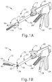
- FIGS. 1-6 depict an exemplary surgical stapling and severing instrument (10) that is sized for insertion, in a nonarticulated state as depicted in FIG. 1A , through a trocar cannula passageway to a surgical site in a patient for performing a surgical procedure.
- Surgical stapling and severing instrument (10) includes handle portion (20) connected to implement portion (22), the latter further comprising shaft (23) distally terminating in an articulation mechanism (11) and a distally attached end effector (12). Once articulation mechanism (11) and end effector (12) are inserted through the cannula passageway of a trocar, articulation mechanism (11) may be remotely articulated, as depicted in FIG.
- end effector (12) may reach behind an organ or approach tissue from a desired angle or for other reasons.
- terms such as “proximal” and “distal” are used herein with reference to a clinician gripping handle portion (20) of instrument (10).
- end effector (12) is distal with respect to the more proximal handle portion (20).
- spatial terms such as “vertical” and “horizontal” are used herein with respect to the drawings.
- surgical instruments are used in many orientations and positions, and these terms are not intended to be limiting and absolute.
- End effector (12) of the present example includes a lower jaw (16) and a pivotable anvil (18).
- Handle portion (20) includes pistol grip (24) toward which closure trigger (26) is pivotally drawn by the clinician to cause clamping, or closing, of the anvil (18) toward lower jaw (16) of end effector (12).
- Such closing of anvil (18) is provided through an outmost closure sleeve (32), which longitudinally translates relative to handle portion (20) in response to pivoting of closure trigger (26) relative to pistol grip (24).
- a distal closure ring (33) of closure sleeve (32) is indirectly supported by frame (34) of implement portion (22).
- a proximal closure tube (35) of closure sleeve (32) communicates with the distal closure ring (33).
- Frame (34) is flexibly attached to lower jaw (16) via articulation mechanism (11), enabling articulation in a single plane.
- Frame (34) also longitudinally slidingly supports a firing drive member (not shown) that extends through shaft (23) and communicates a firing motion from firing trigger (28) to firing bar (14).
- Firing trigger (28) is farther outboard of closure trigger (26) and is pivotally drawn by the clinician to cause the stapling and severing of clamped tissue in end effector (12), as will be described in greater detail below.
- release button (30) is depressed to release the tissue from end effector (12).
- FIGS. 2-5 depict end effector (12) employing an E-beam firing bar (14) to perform a number of functions.
- firing bar (14) includes a transversely oriented upper pin (38), a firing bar cap (44), a transversely oriented middle pin (46), and a distally presented cutting edge (48).
- Upper pin (38) is positioned and translatable within an anvil pocket (40) of anvil (18).
- Firing bar cap (44) slidably engages a lower surface of lower jaw (16) by having firing bar (14) extend through channel slot (45) (shown in FIG. 3B ) that is formed through lower jaw (16).
- Middle pin (46) slidingly engages a top surface of lower jaw (16), cooperating with firing bar cap (44). Thereby, firing bar (14) affirmatively spaces end effector (12) during firing, overcoming pinching that may occur between anvil (18) and lower jaw (16) with a minimal amount of clamped tissue and overcoming staple malformation with an excessive amount of clamped tissue.
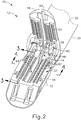
- FIG. 2 shows firing bar (14) proximally positioned and anvil (18) pivoted to an open position, allowing an unspent staple cartridge (37) to be removably installed into a channel of lower jaw (16).
- staple cartridge (37) of this example includes a cartridge body (70), which presents an upper deck (72) and is coupled with a lower cartridge tray (74).
- a vertical slot (49) is formed through part of staple cartridge (37).
- three rows of staple apertures (51) are formed through upper deck (72) on one side of vertical slot (49), with another set of three rows of staple apertures (51) being formed through upper deck (72) on the other side of vertical slot (49).
- a wedge sled (41) and a plurality of staple drivers (43) are captured between cartridge body (70) and tray (74), with wedge sled (41) being located proximal to staple drivers (43).
- Wedge sled (41) is movable longitudinally within staple cartridge (37); while staple drivers (43) are movable vertically within staple cartridge (37).
- Staples (47) are also positioned within cartridge body (70), above corresponding staple drivers (43).
- each staple (47) is driven vertically within cartridge body (70) by a staple driver (43) to drive staple (47) out through an associated staple aperture (51).
- wedge sled (41) presents inclined cam surfaces that urge staple drivers (43) upwardly as wedge sled (41) is driven distally through staple cartridge (37).
- firing bar (14) is advanced in engagement with anvil (18) by having upper pin (38) enter a longitudinal anvil slot (42).
- a pusher block (80) is located at the distal end of firing bar (14), and is configured to engage wedge sled (41) such that wedge sled (41) is pushed distally by pusher block (80) as firing bar (14) is advanced distally through staple cartridge (37).
- cutting edge (48) of firing bar (14) enters vertical slot (49) of staple cartridge (37), severing tissue clamped between staple cartridge (37) and anvil (18).
- middle pin (46) and pusher block (80) together actuate staple cartridge (37) by entering into slot (49) within staple cartridge (37), driving wedge sled (41) into upward camming contact with staple drivers (43) that in turn drive staples (47) out through staple apertures (51) and into forming contact with staple forming pockets (53) on the inner surface of anvil (18).
- FIG. 3B depicts firing bar (14) fully distally translated after completing severing and stapling tissue.
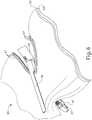
- FIG. 6 shows end effector (12) having been actuated through a single stroke through tissue (90).
- Cutting edge (48) has cut through tissue (90), while staple drivers (43) have driven three alternating rows of staples (47) through the tissue (90) on each side of the cut line produced by cutting edge (48).
- Staples (47) are all oriented substantially parallel to the cut line in this example, though it should be understood that staples (47) may be positioned at any suitable orientations.
- end effector (12) is withdrawn from the trocar after the first stroke is complete, spent staple cartridge (37) is replaced with a new staple cartridge, and end effector (12) is then again inserted through the trocar to reach the stapling site for further cutting and stapling. This process may be repeated until the desired amount of cuts and staples (47) have been provided.
- Anvil (18) may need to be closed to facilitate insertion and withdrawal through the trocar; and anvil (18) may need to be opened to facilitate replacement of staple cartridge (37).
- cutting edge (48) may sever tissue substantially contemporaneously with staples (47) being driven through tissue during each actuation stroke.
- cutting edge (48) just slightly lags behind driving of staples (47), such that a staple (47) is driven through the tissue just before cutting edge (48) passes through the same region of tissue, though it should be understood that this order may be reversed or that cutting edge (48) may be directly synchronized with adjacent staples.
- FIG. 6 shows end effector (12) being actuated in two layers (92, 94) of tissue (90), it should be understood that end effector (12) may be actuated through a single layer of tissue (90) or more than two layers (92, 94) of tissue.
- instrument (10) may be configured and operable in accordance with any of the teachings of U.S. Pat. No. 4,805,823 ; U.S. Pat. No. 5,415,334 ; U.S. Pat. No. 5,465,895 ; U.S. Pat. No. 5,597,107 ; U.S. Pat. No.
- the length of tissue transaction achieved during each actuation stroke of instrument (10) is limited by the length of cartridge (37). If the operator wishes to transect tissue along a length greater than the length of cartridge (37), the operator will need to reload instrument (10) with a new cartridge (37). The same principle will apply in the event that the operator wishes to transect tissue in one location in the patient and then transect tissue in another location in the patient - the operator will still need to reload instrument (10) with a new cartridge (37) each time the operator wishes to actuate instrument (10).
- the operator will need to remove end effector (12) from the patient to remove the spent cartridge (37) and load a new cartridge (37); then re-insert end effector (12) in the patient. This process may be tedious in some settings. It may therefore be desirable to enable an operator to perform transections (including fasteners along each side of the transaction) along a length greater than that achievable using cartridge (37). Similarly, it may be desirable to enable an operator to perform several transections (including fasteners along each side of each transaction) within a patient using an instrument that does not need to be removed from the patient between each transaction.
- instrument (10) that are operable to provide these results. Other variations will be apparent to those of ordinary skill in the art in view of the teachings herein.
- FIGS. 7-12 show an exemplary alternative end effector (100) that may be incorporated into an instrument like instrument (10) discussed above.
- End effector (100) of this example comprises an upper jaw (110), a lower jaw (120), and a tissue cutting member (130).
- Upper jaw (110) is pivotable relative to lower jaw (120), such that jaws (110, 120) may be selectively opened and closed to capture tissue.
- Various suitable ways in which upper jaw (110) may be pivoted relative to lower jaw (120) will be apparent to those of ordinary skill in the art in view of the teachings herein.
- end effector (100) is operable to transect layers (92, 94) of tissue and fasten the layers (92, 94) of tissue together on each side of the transaction line using a fastening assembly formed by a wire (170) and a buttress strip (160).
- End effector (100) may thus be used in a manner similar to end effector (12) described above, with the fastening assembly formed by a wire (170) and a buttress strip (160) being similar in effect to formed staples (47) applied by end effector (12).
- end effector (100) of the present example will avoid the need to replace an equivalent of cartridge (37), thus facilitating longer transaction lines and/or a series of transections within a patient without having to repeatedly remove end effector (100) from the patient.
- upper jaw (110) includes a pair of rolling anvils (140) that are driven by a drive shaft (150).
- Anvils (140) rotate about an axis that is perpendicular to the longitudinal axis of end effector (150); while drive shaft (150) rotates about an axis that is parallel to the longitudinal axis of end effector (150).
- Anvils (140) rotate together simultaneously in the same direction.
- Drive shaft (150) is coupled with a rotary drive source (152), which may include a motor and/or any other suitable kind of rotary drive source (152).
- upper jaw (110) defines a slot (112) that is configured to slidably receive tissue cutting member (130).
- Upper jaw (110) also defines a pair of channels (114) and openings (116) on each side of slot (112). Openings (116) are positioned to expose portions of anvils (140). In particular, openings (116) are configured to receive protruding portions (174) of wire (170) to enable anvils (140) to form the fastening assembly as will be described in greater detail below.
- each anvil (140) includes radially extending flanges (142) and forming chamber sidewalls (144), which cooperate to form a series of forming chamber recesses (146) about the perimeter of anvil (140). While six recesses (146) are shown in the present example, it should be understood that any other suitable number of recesses (146) may be used. As will be described in greater detail below, recesses (146) are configured to receive buttress strip (160) and protruding portions (174) of wire (170). Recesses (146) are further configured to deform protruding portions (174) of wire (170) to produce formed portions (176) of wire (170).
- Each anvil (140) also defines a bore (148) that is configured to receive an axle (141).
- Axle (141) is driven by drive shaft (150) as noted above. While both anvils (140) share a common axle (141) in the present example, some other versions may provide separate axles (141) for anvils (140).
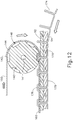
- Buttress strips (160) of the present example are fed over the top of anvils (140) as shown in FIG. 12 .
- Buttress strips (160) may be formed of any suitable material(s), including but not limited to the following: a polyglutamic acid (PGA) polymer; polyglycolic acid:Trimethylene carbonate (PGA:TMC); bovine pericardium; compressible hemostat material such as, for example, oxidized regenerated cellulose (ORC) or a bioabsorbable foam (e.g., compressed into sheet form); polydioxanone (PDS); polyglycerol sebacate (PGS); polyglycolic acid (PGA); polycaprolactone (PCL); polylactic acid (PLA); polyhydroxyalkanoate (PHA); poliglecaprone (PGCL); polylactic acid (PLA or PLLA); polyhydroxyalkanoate (PHA); polycaprolactone (PCL); polyurethane; polypropylene (PP); polyethylene (PE); polycarbonate
- buttress strips (160) may be formed of foamed elastomers and/or porous elastomers, such as, for example, silicone, polyisoprene, expanded polytetrafluoroethylene (ePTFE), co-polyetherester urethane foam, and/or any other suitable material(s).
- foamed elastomers and/or porous elastomers such as, for example, silicone, polyisoprene, expanded polytetrafluoroethylene (ePTFE), co-polyetherester urethane foam, and/or any other suitable material(s).
- Each anvil (140) receives a respective buttress strip (160).
- anvils (140) include protrusions and buttress strips (160) include openings that cooperate with the protrusions of anvils (140) to provide a tractor feed configuration, such that anvils (140) directly pull buttress strips (160) distally when anvils rotate (140).
- buttress strips (160) may be advanced distally will be apparent to those of ordinary skill in the art in view of the teachings herein.
- each buttress strip (160) is released from a respective spool or reel (162).
- Reels (162) may be located within a handle portion like handle portion (20) and/or in any other suitable location.
- Reels (162) may be configured to freely release buttress strips (160) as buttress strips (160) are pulled distally and/or reels (162) may include features that selectively lock/unlock the release of buttress strips (160) from reels (162). In some versions, reels (162) are powered to rotate and thereby actively feed buttress strips (160).
- buttress strips (160) are configured to receive respective protruding portions (174) of wire (170) as protruding portions (174) enter recesses (146).
- Buttress strips (160) may include preformed openings that facilitate passage of protruding portions (174) through buttress strips (160).
- protruding portions (174) may simply pierce or otherwise penetrate buttress strips (160) as protruding portions (174) enter recesses (146).
- lower law (120) defines a slot (122) that is configured to slidably receive tissue cutting member (130).
- Lower jaw (120) also defines a pair of channels (124) that terminate at openings (126) on each side of slot (122). Openings (126) are positioned to align with openings (116) of upper jaw (110) when upper law (110) is in a closed position relative to lower jaw (120).
- channel (124) is sized to receive wire (170).
- channel (124) is configured to enable communication of wire (170) distally through lower jaw (120), without causing interference with protruding portions (174).
- Channel (124) further includes a redirection zone (129) configured to redirect the travel of wire (170) from a distal direction to a proximal direction as wire (170) approaches the distal end of lower jaw (120).
- a roller (125) is positioned at redirection zone (129) and rotates freely relative to lower jaw (120), thereby reducing friction between wire (170) and lower jaw (120) at redirection zone (129).
- roller (125) is merely optional.
- the terminal end of each channel (124) includes a ramp (127) adjacent to opening (126).
- Each ramp (127) defines a shallow obtuse angle relative to the upper deck surface (121) of lower jaw (120), enabling wires (170) to exit openings (126) along paths that are nearly parallel to the upper deck surface (121) of lower jaw (120).
- Various suitable angles for ramps (127) will be apparent to those of ordinary skill in the art in view of the teachings herein.
- each wire (170) includes a plurality of transversely protruding portions (174).
- Protruding portions (174) are separated by base lengths (178) of wire (170).
- Wire (170) is malleable such that formed portions (176) will substantially maintain their shape once formed.
- Wire (170) may be formed of various kinds of metal and/or any other suitable kind of material(s).
- Protruding portions (174) are configured to penetrate layers of tissue (92, 94) as shown in FIG. 12 . In some versions, protruding portions (174) are sharpened to facilitate tissue penetration, though such sharpening is not necessarily required.
- wire (170) has enough flexibility to enable formation of formed portions (176) by anvils (140), wire (170) has enough rigidity for protruding portions (174) to substantially maintain their configuration while protruding portions (174) penetrate tissue.
- Various suitable materials and configurations that may be used for forming wire (170) will be apparent to those of ordinary skill in the art in view of the teachings herein.
- each wire (170) is released from a respective spool or reel (172).
- Reels (172) may be located within a handle portion like handle portion (20) and/or in any other suitable location.
- Reels (172) may be configured to freely release wires (170) as wires (170) are pulled distally and/or reels (172) may include features that selectively lock/unlock the release of wires (170) from reels (172). In some versions, reels (172) are powered to rotate and thereby actively feed wire (170).
- Tissue cutting member (130) is similar to firing bar (14) described above in that tissue cutting member (130) has a distal cutting edge (134) that is configured to sever tissue captured between jaws (110, 120).
- tissue cutting member (130) is operable to drive upper jaw (110) toward lower jaw (120) as tissue cutting member (130) is advanced distally.
- upper jaw (110) is driven toward lower jaw by a separate feature (e.g., a feature similar to closure sleeve (32), etc.).
- tissue cutting member (130) of the present example comprises an upper flange (136) and a lower flange (138) at the top and bottom, respectively, of distal cutting edge (134).
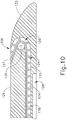
- Lower flange (138) is slidably disposed in a channel (128) formed in lower jaw (120) as shown in FIG. (10 ); while upper flange (136) is slidably disposed in a channel (not shown) formed in upper jaw (110).
- Distal cutting edge (134) is slidably disposed in slots (112, 122) of jaws (110, 120).
- Tissue cutting member (130) is in communication with a drive assembly (132), which is operable to drive tissue cutting member distally through slots (112, 122) in jaws (110, 120).
- drive assembly (132) includes a motor.
- rotary drive source (152) and drive assembly (132) are driven by the same, common motor.
- drive assembly (132) may include a manual mechanical drive train that is actuated by a user input like firing trigger (28) described above.
- tissue cutting member (130) Regardless of whether tissue cutting member (130) is advanced by motor or manually, some versions of tissue cutting member (130) are operable to vibrate at an ultrasonic frequency (e.g., approximately 55.5 kHz) to simultaneously sever tissue and denature the proteins in adjacent tissue cells, thereby providing a coagulative effect with relatively little thermal spread.
- drive assembly (132) may include one or more piezoelectric elements that are operable to convert electrical power into ultrasonic vibrations.
- tissue cutting member (130) may be selectively activated with RF energy.
- end effector (100) provides a return path for such RF energy, such that end effector (100) operates as a biopolar electrosurgical end effector.
- a ground pad is placed on or under the patient, such that end effector (100) operates as a monopolar electrosurgical end effector.
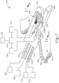
- control module (104) is operable to selectively provide power from power source (102) to drive assembly (132) and/or rotary drive source (152) based on user input and/or based on other information.
- control module (104) may include one or more switches that are in communication with a user input (e.g., firing trigger (28), etc.), that thereby selectively complete a circuit between the user input, drive assembly (132), rotary drive source (152), and power source (102).
- control module (104) may be in communication with one or more sensors (e.g., encoder wheel, reed switch(es), tissue contacting electrodes, etc.) that are operable to detect an operational parameter associated with end effector (100) (e.g., the presence of tissue between jaws (110, 120), etc.) and control activation of rotary drive source (152) and/or power source (102) based on such information.
- sensors e.g., encoder wheel, reed switch(es), tissue contacting electrodes, etc.
- control activation of rotary drive source (152) and/or power source (102) e.g., the presence of tissue between jaws (110, 120), etc.
- power source (102) may comprise a battery (e..g, located within handle portion (20), etc.), an external power source (e.g., coupled with handle portion (20) via cable), and/or some other kind of power source (102).
- power source (102) may be eliminated. For instance, all of the operation of end effector (100) may be driven manually by the hand of the operator.
- the operator may position layers (92, 94) of tissue between jaws (110, 120), then drive upper jaw (110) toward lower jaw (120) to clamp the layers (92, 94) of tissue between jaws (110, 120).
- the operator may then actuate rotary drive source (152) to rotate anvils (140).
- This rotation of anvils (140) pulls buttress strips (160) distally and around anvils (140).
- the rotation of anvils (140) also pulls wires (170) distally around rollers (125).
- tissue cutting member (130) Before, during, and/or after the layers (92, 94) of tissue are secured by formed wire (170) and buttress strip (160), tissue cutting member (130) may be actuated to sever the tissue. In particular, tissue cutting member (130) may transect the layers (92, 94) tissue along a path that is parallel to and between the fastener assemblies formed by wire (170) and buttress strip (160). The net result may look similar to what is shown in FIG. 7 , where the fastener assemblies formed by wire (170) and buttress strip (160) are positioned adjacent to the tissue transaction created by tissue cutting member (130).
- slots (112, 122) distally terminate proximal to openings (116, 126), such that tissue cutting member (130) does not travel distally to the point where layers (92, 94) of tissue are fastened by wire (170) and buttress strip (160). This may ensure that the layers (92, 94) of tissue are fastened before the layers (92, 94) of tissue are transected.
- drive assembly (132) may be manually and/or automatically controlled to ensure proper timing of tissue cutting member (130) actuation (e.g., in relation to fastening by wire (170) and buttress strip (160) and/or otherwise).
- fastener assemblies formed by wire (170) and buttress strip (160) may provide anchoring of layers (92, 94) of tissue and may also provide hemostasis at the transection edges created by tissue cutting member (130). Hemostasis may be further enhanced if jaws (110, 120) are used to substantially compress the layers (92, 94) of tissue when the fastener assembly is deployed. It should also be understood that the above process may be carried out and repeated for as long as desired, enabling the operator to create secured transections having an effectively indefinite length (e.g., especially if a significant amount of buttress strip (160) and wire (170) is preloaded), without having to remove end effector (100) from the patient.
- an effectively indefinite length e.g., especially if a significant amount of buttress strip (160) and wire (170) is preloaded
- the above process may be repeated to create several separate secured transections within the patient, without having to remove end effector (100) from the patient.
- the operator may simply use a conventional cutting instrument to cut wire (170) and/or buttress strip (160) before moving to the latter transection site.
- end effector (100) includes a feature enabling selective adjustment of the gap distance between closed jaws (110, 120), which may effectively vary the height of the fasteners ultimately formed by wire (170). Such adjustability may be desired to account for varying tissue thicknesses.
- end effector (100) may enable adjustment of the distance between axle (141) and the lower surface of upper jaw (110), which may effectively vary the height of fasteners ultimately formed by wire (170). It should also be understood that gap adjustment and/or fastener height adjustment may not be required.
- Other variations for the construction, use, and operability of end effector (100) will be apparent to those of ordinary skill in the art in view of the teachings herein.
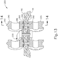
- FIGS. 13-14 show an exemplary alternative end effector (200) that may be used in place of end effector (100) described above.
- End effector (200) of this example comprises a pair of upper rolling anvils (240) and a pair of lower rolling guides (225).
- Anvils (240) and guides (225) are provided in opposing pairs, and each pair is positioned on opposing sides of a tissue cutting member (230). It should be understood that anvils (240) may be located in an upper jaw like upper jaw (110); while guides (225) may be located in a lower jaw like lower jaw (120).
- Anvils (240) are thus similar to anvils (140), with guides (225) being similar to rollers (125) and tissue cutting member (230) being similar to tissue cutting member (130).
- Tissue cutting member (230) may be operable to translate to sever tissue, to vibrate at ultrasonic frequencies to sever and coagulate tissue, and/or to deliver RF energy to tissue, all as described above with respect to tissue cutting member (130).
- tissue cutting member (230) is positioned to cut layers (92, 94) of tissue after the layers (92, 94) are secured by the fastening assembly described below, though it should be understood that tissue cutting member (230) may instead be otherwise positioned.
- End effector (200) of the present example is configured to form a fastening assembly with a rivet strip (270), rivets (280), and a buttress strip (260).
- buttress strip (260) may be viewed as a substitute for buttress strip (160) described above; while rivet strip (270) and rivets (280) may together be viewed as a substitute for wire (170).
- each strip (260, 270) may be formed of any of the various materials listed above as being suitable for forming buttress strips (160).
- Various other suitable materials and configurations that may be used for strips (260, 270) will be apparent to those of ordinary skill in the art in view of the teachings herein.
- buttress strip (260) may be formed of one material (or combination of materials) while rivet strip (270) is formed of a different kind of material (or combination of materials).
- Buttress strip (260) may be fed from a reel or some other kind of source; while rivet strip (270) and rivets (280) may also be fed from a reel or some other kind of source.
- Each rivet (280) comprises a lower flange (282) and a hollow shaft section (284) with an open free end (286).
- Rivets (280) are disposed in rivet strip (270), with lower flanges (282) being positioned below rivet strip (270) to prevent rivets (280) from being pulled through rivet strip (270).
- Rivets (280) are configured for hollow shaft section (284) to penetrate layers (92, 94) of tissue and pass through buttress strip (260).
- buttress strip (260) includes preformed openings that are spaced and configured to receive hollow shaft sections (284).
- hollow shaft sections (284) form their own openings in buttress strip (260).
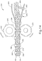
- anvil (240) deforms free end (286) to form a rivet head on the top of buttress strip (260) as best seen in FIG. 14 .
- anvil (240) includes spiked projections (242) that extend radially outwardly and that are spaced and configured to enter successive free ends (286) as the fastening assembly is fed between rolling anvil (240) and rolling guide (225).
- the spiked shaped of projections (242) facilitates entry of projections into free ends (286) and further facilitates the outward spreading of free ends (286) to form rivet heads.
- Rivets (280) are formed of a malleable material such that formed free ends (286) substantially maintain the rivet head configuration after the rivet heads are formed by projections (242).
- rivets (280) may be formed of various kinds of metal (e.g., micro-stamped titanium, titanium based alloys, etc.) and/or any other suitable material(s) (e.g., absorbable poliglecaprone (PGCL) such as MONOCRYL by Ehticon, Inc., of Somerville, New Jersey, etc.).
- PGCL absorbable poliglecaprone
- MONOCRYL absorbable poliglecaprone
- anvils (240) and/or guides (225) may be driven by something similar to drive shaft (150), etc. Such driven motion of anvils (240) and/or guides (225) may further drive strips (260, 270) relative to tissue, as shown in FIG. 14 .
- End effector (200) may be operated in a manner similar to the operation of end effector (100) described above. It should also be understood that the above process may be carried out and repeated for as long as desired, enabling the operator to create secured transections having an effectively indefinite length (e.g., especially if a significant amount of strips (260, 270) and rivets (280) is preloaded), without having to remove end effector (200) from the patient. Similarly, the above process may be repeated to create several separate secured transections within the patient, without having to remove end effector (200) from the patient.
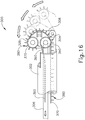
- FIGS. 15-18 show another exemplary end effector (300) that may be used to provide transection and continuous fastening of tissue, similar to end effectors (100, 200) described above.
- End effector (300) of this example is disposed at the distal end of a shaft (302).
- End effector (300) comprises a chassis (308) that is joined to shaft (302) by a pivot pin (304), such that end effector (300) configured to pivot relative to shaft (302) about pivot pin (304) to transition between a straight configuration ( FIG. 16 ) and a pivoted configuration ( FIG. 17 ).
- end effector (300) When end effector (300) is in a straight configuration, end effector (300) and shaft (302) may be fed through a conventional trocar cannula (400) to reach a surgical site within a patient, in a minimally invasive manner. Once end effector (300) has been positioned within the patient, end effector (300) may then be pivoted relative to shaft (302) as desired to achieve an ideal orientation based on the patient's anatomy and the location of the tissue that is to be transected/fastened. The desired degree of pivoting may vary based on a variety of other factors.
- end effector (300) is selectively pivoted by translating a band (306) that extends through shaft (302) and is coupled with chassis (308).
- Band (306) is pulled proximally to transition end effector (300) from the straight configuration to the pivoted configuration.
- end effector (300) may be oriented at various angles relative to shaft (302) when end effector (300) is in a pivoted configuration.
- end effector (300) is resiliently biased to assume the straight configuration such that band (306) is simply released in order to transition end effector (300) from a pivoted configuration back toward the straight configuration.
- band (306) is actively pushed distally to transition end effector (300) from a pivoted configuration back toward the straight configuration.
- band (306) may be actuated will be apparent to those of ordinary skill in the art in view of the teachings herein.
- end effector (300) may be transitioned between a straight configuration and a pivoted configuration will be apparent to those of ordinary skill in the art in view of the teachings herein.
- a cable, a rack and pinion, a chain drive, and/or various other suitable features may be used in addition to or in lieu of band (306).
- End effector (300) further comprises a pair of rolling anvils (340) and rolling guides (325), all of which are rotatably secured to chassis (308).
- Anvils (340) and guides (325) are arranged similar to anvils (240) and guides (225) as described above.
- anvils (340) and guides (325) are provided in opposing pairs, and each pair is positioned on opposing sides of a tissue cutting member (330).
- end effector (300) of this example lacks a pivoting jaw.
- the spacing between anvils (340) and guides (325) is fixed.
- end effector (300) includes a feature that is operable to vary the spacing between anvils (340) and guides (325). It should also be understood that anvils (340) and/or guides (325) may be rotatably driven relative to chassis (308), such as via drive shaft, via belt, via cable, and/or in any other suitable fashion as will be apparent to those of ordinary skill in the art in view of the teachings herein.
- Tissue cutting member (330) is configured to cut tissue and may be fixedly secured to chassis (308) or may be operable to move relative to chassis (308).
- tissue cutting member (330) may be operable to translate to sever tissue, to vibrate at ultrasonic frequencies to sever and coagulate tissue, and/or to deliver RF energy to tissue, all as described above with respect to tissue cutting member (130).
- tissue cutting member (330) is positioned to cut layers (92, 94) of tissue after the layers (92, 94) are secured by the fastening assembly described below, though it should be understood that tissue cutting member (330) may instead be otherwise positioned.
- End effector (300) of the present example is configured to form a fastening assembly with a fastener strip (370), fasteners (380), and a buttress strip (360).
- buttress strip (360) may be viewed as a substitute for buttress strip (160) described above; while fastener strip (370) and fasteners (380) may together be viewed as a substitute for wire (170).
- each strip (360, 370) may be formed of any of the various materials listed above as being suitable for forming buttress strips (160).
- Various other suitable materials and configurations that may be used for strips (360, 370) will be apparent to those of ordinary skill in the art in view of the teachings herein.
- buttress strip (360) may be formed of one material (or combination of materials) while fastener strip (370) is formed of a different kind of material (or combination of materials).
- Buttress strip (360) may be fed from a reel or some other kind of source; while fastener strip (370) and fasteners (380) may also be fed from a reel or some other kind of source.
- Each fastener (380) comprises a lower flange (382) and a shaft section (384) with a barbed free end (386).
- Fasteners (380) are disposed in fastener strip (370), with lower flanges (382) being positioned below fastener strip (370) to prevent fasteners (380) from being pulled through fastener strip (370).
- Fasteners (380) are configured for barbed free ends (386) to penetrate layers (92, 94) of tissue and pass through buttress strip (360).
- buttress strip (360) includes preformed openings that are spaced and configured to receive barbed free ends (386).
- barbed free ends (386) form their own openings in buttress strip (360).
- Each anvil (340) includes a pair of radially extending flanges (342) and recesses (346) that are angularly disposed about the perimeter of anvil (340). While eight recesses (346) are shown in the present example, it should be understood that any other suitable number of recesses (346) may be used.
- Flanges (342) are configured to guide and laterally retain buttress strip (360) relative to anvil (340); while recesses (346) are configured to receive barbed free ends (386) of fasteners (380).
- recesses (346) are configured to allow barbed free ends (386) to pass through buttress strip (360), without any resistance being provided by anvil (340).
- anvil (340) of the present example does not deform fasteners (380).
- Guides (325) include recesses (326) that are configured to guide and laterally retain flanges (382) relative to guides (325).
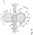
- Recesses (346, 326) are configured to successively align with each other at the interface of tissue layers (92, 94) during rotation of anvils (340) and guides (325), as shown in FIG. 18 . It should be understood that the barbed configuration of barbed free ends (386) substantially prevents barbed free ends (386) from being pulled back through buttress strip (360) after barbed free ends (386) are passed through buttress strip (360).
- fasteners (380) may be formed of various kinds of metal (e.g., micro-stamped titanium, titanium based alloys, etc.) and/or any other suitable material(s) (e.g., absorbable poliglecaprone (PGCL) such as MONOCRYL by Ehticon, Inc., of Somerville, New Jersey, etc.).
- PGCL absorbable poliglecaprone
- MONOCRYL MONOCRYL by Ehticon, Inc., of Somerville, New Jersey, etc.
- tissue cutting member (330) may provide hemostasis of the tissue, substantially preventing bleeding of the tissue at the transection cut formed by tissue cutting member (330).
- anvils (340) and/or guides (325) may be driven to rotate. Such driven motion of anvils (340) and/or guides (325) may further drive strips (360, 370) relative to tissue, as shown in FIG. 18 .
- End effector (300) may be operated in a manner similar to the operation of end effector (100) described above. It should also be understood that the above process may be carried out and repeated for as long as desired, enabling the operator to create secured transections having an effectively indefinite length (e.g., especially if a significant amount of strips (360, 370) and fasteners (380) is preloaded), without having to remove end effector (300) from the patient. Similarly, the above process may be repeated to create several separate secured transections within the patient, without having to remove end effector (300) from the patient.
- Versions of the devices described above may have application in conventional medical treatments and procedures conducted by a medical professional, as well as application in robotic-assisted medical treatments and procedures.
- various teachings herein may be readily incorporated into a robotic surgical system such as the DAVINCITM system by Intuitive Surgical, Inc., of Sunnyvale, California.
- Versions described above may be designed to be disposed of after a single use, or they can be designed to be used multiple times. Versions may, in either or both cases, be reconditioned for reuse after at least one use. Reconditioning may include any combination of the steps of disassembly of the device, followed by cleaning or replacement of particular pieces, and subsequent reassembly. In particular, some versions of the device may be disassembled, and any number of the particular pieces or parts of the device may be selectively replaced or removed in any combination. Upon cleaning and/or replacement of particular parts, some versions of the device may be reassembled for subsequent use either at a reconditioning facility, or by a user immediately prior to a procedure.
- reconditioning of a device may utilize a variety of techniques for disassembly, cleaning/replacement, and reassembly. Use of such techniques, and the resulting reconditioned device, are all within the scope of the present application.
- versions described herein may be sterilized before and/or after a procedure.
- the device is placed in a closed and sealed container, such as a plastic or TYVEK bag.
- the container and device may then be placed in a field of radiation that can penetrate the container, such as gamma radiation, x-rays, or high-energy electrons.
- the radiation may kill bacteria on the device and in the container.
- the sterilized device may then be stored in the sterile container for later use.
- a device may also be sterilized using any other technique known in the art, including but not limited to beta or gamma radiation, ethylene oxide, or steam.
Abstract
Description
- In some settings, endoscopic surgical instruments may be preferred over traditional open surgical devices since a smaller incision may reduce the post-operative recovery time and complications. Consequently, some endoscopic surgical instruments may be suitable for placement of a distal end effector at a desired surgical site through the cannula of a trocar. These distal end effectors may engage tissue in a number of ways to achieve a diagnostic or therapeutic effect (e.g., endocutter, grasper, cutter, stapler, clip applier, access device, drug/gene therapy delivery device, and energy delivery device using ultrasound, RF, laser, etc.). Endoscopic surgical instruments may include a shaft between the end effector and a handle portion, which is manipulated by the clinician. Such a shaft may enable insertion to a desired depth and rotation about the longitudinal axis of the shaft, thereby facilitating positioning of the end effector within the patient. Positioning of an end effector may be further facilitated through inclusion of one or more articulation joints or features, enabling the end effector to be selectively articulated or otherwise deflected relative to the longitudinal axis of the shaft.
- Examples of endoscopic surgical instruments include surgical staplers. Some such staplers are operable to clamp down on layers of tissue, cut through the clamped layers of tissue, and drive staples through the layers of tissue to substantially seal the severed layers of tissue together near the severed ends of the tissue layers. Merely exemplary surgical staplers are disclosed in
U.S. Pat. No. 4,805,823 , entitled "Pocket Configuration for Internal Organ Staplers," issued February 21, 1989;U.S. Pat. No. 5,415,334 , entitled "Surgical Stapler and Staple Cartridge," issued May 16, 1995;U.S. Pat. No. 5,465,895 , entitled "Surgical Stapler Instrument," issued November 14, 1995;U.S. Pat. No. 5,597,107 , entitled "Surgical Stapler Instrument," issued January 28, 1997;U.S. Pat. No. 5,632,432 , entitled "Surgical Instrument," issued May 27, 1997;U.S. Pat. No. 5,673,840 , entitled "Surgical Instrument," issued October 7, 1997;U.S. Pat. No. 5,704,534 , entitled "Articulation Assembly for Surgical Instruments," issued January 6, 1998;U.S. Pat. No. 5,814,055 , entitled "Surgical Clamping Mechanism," issued September 29, 1998;U.S. Pat. No. 6,978,921 , entitled "Surgical Stapling Instrument Incorporating an E-Beam Firing Mechanism," issued December 27, 2005;U.S. Pat. No. 7,000,818 , entitled "Surgical Stapling Instrument Having Separate Distinct Closing and Firing Systems," issued February 21, 2006;U.S. Pat. No. 7,143,923 , entitled "Surgical Stapling Instrument Having a Firing Lockout for an Unclosed Anvil," issued December 5, 2006;U.S. Pat. No. 7,303,108 , entitled "Surgical Stapling Instrument Incorporating a Multi-Stroke Firing Mechanism with a Flexible Rack," issued December 4, 2007;U.S. Pat. No. 7,367,485 , entitled "Surgical Stapling Instrument Incorporating a Multistroke Firing Mechanism Having a Rotary Transmission," issued May 6, 2008;U.S. Pat. No. 7,380,695 , entitled "Surgical Stapling Instrument Having a Single Lockout Mechanism for Prevention of Firing," issued June 3, 2008;U.S. Pat. No. 7,380,696 , entitled "Articulating Surgical Stapling Instrument Incorporating a Two-Piece E-Beam Firing Mechanism," issued June 3, 2008;U.S. Pat. No. 7,404,508 , entitled "Surgical Stapling and Cutting Device," issued July 29, 2008;U.S. Pat. No. 7,434,715 , entitled "Surgical Stapling Instrument Having Multistroke Firing with Opening Lockout," issued October 14, 2008;U.S. Pat. No. 7,721,930 , entitled "Disposable Cartridge with Adhesive for Use with a Stapling Device," issued May 25, 2010;U.S. Pub. No. 2010/0264193 , entitled "Surgical Stapling Instrument with An Articulatable End Effector," published October 21, 2010; andU.S. Pub. No. 2012/0239012 , entitled "Motor-Driven Surgical Cutting Instrument with Electric Actuator Directional Control Assembly," published September 20, 2012. The disclosure of each of the above-cited U.S. Patents and U.S. Patent Publications is incorporated by reference herein. - While the surgical staplers referred to above are described as being used in endoscopic procedures, it should be understood that such surgical staplers may also be used in open procedures and/or other non-endoscopic procedures. By way of example only, a surgical stapler may be inserted through a thoracotomy and thereby between a patient's ribs to reach one or more organs in a thoracic surgical procedure that does not use a trocar as a conduit for the stapler. Such procedures may include the use of the stapler to sever and close a vessel leading to a lung. For instance, the vessels leading to an organ may be severed and closed by a stapler before removal of the organ from the thoracic cavity. Of course, surgical staplers may be used in various other settings and procedures.
- While various kinds of surgical stapling instruments and associated components have been made and used, it is believed that no one prior to the inventor(s) has made or used the invention described in the appended claims.
- The accompanying drawings, which are incorporated in and constitute a part of this specification, illustrate embodiments of the invention, and, together with the general description of the invention given above, and the detailed description of the embodiments given below, serve to explain the principles of the present invention.
-
FIG. 1A depicts a perspective view of an exemplary articulating surgical stapling instrument with an end effector in a nonarticulated position; -
FIG. 1B depicts a perspective view of the surgical instrument ofFIG. 1A with an end effector in an articulated position; -
FIG. 2 depicts a perspective view of an opened end effector of the surgical instrument ofFIGS. 1A-1B ; -
FIG. 3A depicts a side cross-sectional view of the end effector ofFIG. 2 , taken along line 3-3 ofFIG. 2 , with the firing bar in a proximal position; -
FIG. 3B depicts a side cross-sectional view of the end effector ofFIG. 2 , taken along line 3-3 ofFIG. 2 , but showing the firing bar in a distal position; -
FIG. 4 depicts an end cross-sectional view of the end effector ofFIG. 2 , taken along line 4-4 ofFIG. 2 ; -
FIG. 5 depicts an exploded perspective view of the end effector ofFIG. 2 ; -
FIG. 6 depicts a perspective view of the end effector ofFIG. 2 , positioned at tissue and having been actuated once in the tissue; -
FIG. 7 depicts a schematic view of an exemplary alternative end effector and other components that may be incorporated into the instrument ofFIGS. 1A-1B ; -
FIG. 8 depicts a partial perspective view of the upper jaw of the end effector ofFIG. 7 ; -
FIG. 9 depicts a partial perspective view of the lower jaw of the end effector ofFIG. 7 ; -
FIG. 10 depicts a side cross-sectional view of the lower jaw ofFIG. 9 , taken along line 10-10 ofFIG. 9 ; -
FIG. 11 depicts a cross-sectional end view of the end effector ofFIG. 7 , taken along line 11-11 ofFIG. 7 ; -
FIG. 12 depicts a cross-sectional side view of the end effector ofFIG. 7 , taken along line 12-12 ofFIG. 11 ; -
FIG. 13 depicts a cross-sectional end view of an exemplary alternative end effector that may be incorporated into the instrument ofFIGS. 1A-1B ; -
FIG. 14 depicts a cross-sectional side view of the end effector ofFIG. 13 , taken along line 14-14 ofFIG. 13 ; -
FIG. 15 depicts a side elevational view of another exemplary alternative end effector that may be incorporated into the instrument ofFIGS. 1A-1B , disposed through a trocar in a straight configuration; -
FIG. 16 depicts a side elevational view of the end effector ofFIG. 15 , pivoted to an angled configuration; -
FIG. 17 depicts a perspective view of the end effector ofFIG. 15 transecting and tacking tissue; and -
FIG. 18 depicts a cross-sectional side view of the end effector ofFIG. 15 . - The drawings are not intended to be limiting in any way, and it is contemplated that various embodiments of the invention may be carried out in a variety of other ways, including those not necessarily depicted in the drawings. The accompanying drawings incorporated in and forming a part of the specification illustrate several aspects of the present invention, and together with the description serve to explain the principles of the invention; it being understood, however, that this invention is not limited to the precise arrangements shown.
- The following description of certain examples of the invention should not be used to limit the scope of the present invention. Other examples, features, aspects, embodiments, and advantages of the invention will become apparent to those skilled in the art from the following description, which is by way of illustration, one of the best modes contemplated for carrying out the invention. As will be realized, the invention is capable of other different and obvious aspects, all without departing from the invention. Accordingly, the drawings and descriptions should be regarded as illustrative in nature and not restrictive.
-
FIGS. 1-6 depict an exemplary surgical stapling and severing instrument (10) that is sized for insertion, in a nonarticulated state as depicted inFIG. 1A , through a trocar cannula passageway to a surgical site in a patient for performing a surgical procedure. Surgical stapling and severing instrument (10) includes handle portion (20) connected to implement portion (22), the latter further comprising shaft (23) distally terminating in an articulation mechanism (11) and a distally attached end effector (12). Once articulation mechanism (11) and end effector (12) are inserted through the cannula passageway of a trocar, articulation mechanism (11) may be remotely articulated, as depicted inFIG. 1B , by articulation control (13). Thereby, end effector (12) may reach behind an organ or approach tissue from a desired angle or for other reasons. It should be understood that terms such as "proximal" and "distal" are used herein with reference to a clinician gripping handle portion (20) of instrument (10). Thus, end effector (12) is distal with respect to the more proximal handle portion (20). It will be further appreciated that for convenience and clarity, spatial terms such as "vertical" and "horizontal" are used herein with respect to the drawings. However, surgical instruments are used in many orientations and positions, and these terms are not intended to be limiting and absolute. - End effector (12) of the present example includes a lower jaw (16) and a pivotable anvil (18). Handle portion (20) includes pistol grip (24) toward which closure trigger (26) is pivotally drawn by the clinician to cause clamping, or closing, of the anvil (18) toward lower jaw (16) of end effector (12). Such closing of anvil (18) is provided through an outmost closure sleeve (32), which longitudinally translates relative to handle portion (20) in response to pivoting of closure trigger (26) relative to pistol grip (24). A distal closure ring (33) of closure sleeve (32) is indirectly supported by frame (34) of implement portion (22). At articulation mechanism (11), a proximal closure tube (35) of closure sleeve (32) communicates with the distal closure ring (33). Frame (34) is flexibly attached to lower jaw (16) via articulation mechanism (11), enabling articulation in a single plane. Frame (34) also longitudinally slidingly supports a firing drive member (not shown) that extends through shaft (23) and communicates a firing motion from firing trigger (28) to firing bar (14). Firing trigger (28) is farther outboard of closure trigger (26) and is pivotally drawn by the clinician to cause the stapling and severing of clamped tissue in end effector (12), as will be described in greater detail below. Thereafter, release button (30) is depressed to release the tissue from end effector (12).
-
FIGS. 2-5 depict end effector (12) employing an E-beam firing bar (14) to perform a number of functions. As best seen inFIGS. 3A-3B , firing bar (14) includes a transversely oriented upper pin (38), a firing bar cap (44), a transversely oriented middle pin (46), and a distally presented cutting edge (48). Upper pin (38) is positioned and translatable within an anvil pocket (40) of anvil (18). Firing bar cap (44) slidably engages a lower surface of lower jaw (16) by having firing bar (14) extend through channel slot (45) (shown inFIG. 3B ) that is formed through lower jaw (16). Middle pin (46) slidingly engages a top surface of lower jaw (16), cooperating with firing bar cap (44). Thereby, firing bar (14) affirmatively spaces end effector (12) during firing, overcoming pinching that may occur between anvil (18) and lower jaw (16) with a minimal amount of clamped tissue and overcoming staple malformation with an excessive amount of clamped tissue. -
FIG. 2 shows firing bar (14) proximally positioned and anvil (18) pivoted to an open position, allowing an unspent staple cartridge (37) to be removably installed into a channel of lower jaw (16). As best seen inFIGS. 4-5 , staple cartridge (37) of this example includes a cartridge body (70), which presents an upper deck (72) and is coupled with a lower cartridge tray (74). As best seen inFIG. 2 , a vertical slot (49) is formed through part of staple cartridge (37). As also best seen inFIG. 2 , three rows of staple apertures (51) are formed through upper deck (72) on one side of vertical slot (49), with another set of three rows of staple apertures (51) being formed through upper deck (72) on the other side of vertical slot (49). Referring back toFIGS. 3-5 , a wedge sled (41) and a plurality of staple drivers (43) are captured between cartridge body (70) and tray (74), with wedge sled (41) being located proximal to staple drivers (43). Wedge sled (41) is movable longitudinally within staple cartridge (37); while staple drivers (43) are movable vertically within staple cartridge (37). Staples (47) are also positioned within cartridge body (70), above corresponding staple drivers (43). In particular, each staple (47) is driven vertically within cartridge body (70) by a staple driver (43) to drive staple (47) out through an associated staple aperture (51). As best seen inFIGS. 3A-3B and5 , wedge sled (41) presents inclined cam surfaces that urge staple drivers (43) upwardly as wedge sled (41) is driven distally through staple cartridge (37). - With end effector (12) closed as depicted in
FIG. 3A , firing bar (14) is advanced in engagement with anvil (18) by having upper pin (38) enter a longitudinal anvil slot (42). A pusher block (80) is located at the distal end of firing bar (14), and is configured to engage wedge sled (41) such that wedge sled (41) is pushed distally by pusher block (80) as firing bar (14) is advanced distally through staple cartridge (37). During such firing, cutting edge (48) of firing bar (14) enters vertical slot (49) of staple cartridge (37), severing tissue clamped between staple cartridge (37) and anvil (18). As shown inFIGS. 3A-3B , middle pin (46) and pusher block (80) together actuate staple cartridge (37) by entering into slot (49) within staple cartridge (37), driving wedge sled (41) into upward camming contact with staple drivers (43) that in turn drive staples (47) out through staple apertures (51) and into forming contact with staple forming pockets (53) on the inner surface of anvil (18).FIG. 3B depicts firing bar (14) fully distally translated after completing severing and stapling tissue. -
FIG. 6 shows end effector (12) having been actuated through a single stroke through tissue (90). Cutting edge (48) has cut through tissue (90), while staple drivers (43) have driven three alternating rows of staples (47) through the tissue (90) on each side of the cut line produced by cutting edge (48). Staples (47) are all oriented substantially parallel to the cut line in this example, though it should be understood that staples (47) may be positioned at any suitable orientations. In the present example, end effector (12) is withdrawn from the trocar after the first stroke is complete, spent staple cartridge (37) is replaced with a new staple cartridge, and end effector (12) is then again inserted through the trocar to reach the stapling site for further cutting and stapling. This process may be repeated until the desired amount of cuts and staples (47) have been provided. Anvil (18) may need to be closed to facilitate insertion and withdrawal through the trocar; and anvil (18) may need to be opened to facilitate replacement of staple cartridge (37). - It should be understood that cutting edge (48) may sever tissue substantially contemporaneously with staples (47) being driven through tissue during each actuation stroke. In the present example, cutting edge (48) just slightly lags behind driving of staples (47), such that a staple (47) is driven through the tissue just before cutting edge (48) passes through the same region of tissue, though it should be understood that this order may be reversed or that cutting edge (48) may be directly synchronized with adjacent staples. While
FIG. 6 shows end effector (12) being actuated in two layers (92, 94) of tissue (90), it should be understood that end effector (12) may be actuated through a single layer of tissue (90) or more than two layers (92, 94) of tissue. It should also be understood that the formation and positioning of staples (47) adjacent to the cut line produced by cutting edge (48) may substantially seal the tissue at the cut line, thereby reducing or preventing bleeding and/or leaking of other bodily fluids at the cut line. Various suitable settings and procedures in which instrument (10) may be used will be apparent to those of ordinary skill in the art in view of the teachings herein.
It should be understood that instrument (10) may be configured and operable in accordance with any of the teachings ofU.S. Pat. No. 4,805,823 ;U.S. Pat. No. 5,415,334 ;U.S. Pat. No. 5,465,895 ;U.S. Pat. No. 5,597,107 ;U.S. Pat. No. 5,632,432 ;U.S. Pat. No. 5,673,840 ;U.S. Pat. No. 5,704,534 ;U.S. Pat. No. 5,814,055 ;U.S. Pat. No. 6,978,921 ;U.S. Pat. No. 7,000,818 ;U.S. Pat. No. 7,143,923 ;U.S. Pat. No. 7,303,108 ;U.S. Pat. No. 7,367,485 ;U.S. Pat. No. 7,380,695 ;U.S. Pat. No. 7,380,696 ;U.S. Pat. No. 7,404,508 ;U.S. Pat. No. 7,434,715 ; and/orU.S. Pat. No. 7,721,930 . - As noted above, the disclosures of each of those patents are incorporated by reference herein. Additional exemplary modifications that may be provided for instrument (10) will be described in greater detail below. Various suitable ways in which the below teachings may be incorporated into instrument (10) will be apparent to those of ordinary skill in the art. Similarly, various suitable ways in which the below teachings may be combined with various teachings of the patents cited herein will be apparent to those of ordinary skill in the art. It should also be understood that the below teachings are not limited to instrument (10) or devices taught in the patents cited herein. The below teachings may be readily applied to various other kinds of instruments, including instruments that would not be classified as surgical staplers. Various other suitable devices and settings in which the below teachings may be applied will be apparent to those of ordinary skill in the art in view of the teachings herein.
- It should be understood that the length of tissue transaction achieved during each actuation stroke of instrument (10) is limited by the length of cartridge (37). If the operator wishes to transect tissue along a length greater than the length of cartridge (37), the operator will need to reload instrument (10) with a new cartridge (37). The same principle will apply in the event that the operator wishes to transect tissue in one location in the patient and then transect tissue in another location in the patient - the operator will still need to reload instrument (10) with a new cartridge (37) each time the operator wishes to actuate instrument (10). In some versions the operator will need to remove end effector (12) from the patient to remove the spent cartridge (37) and load a new cartridge (37); then re-insert end effector (12) in the patient. This process may be tedious in some settings. It may therefore be desirable to enable an operator to perform transections (including fasteners along each side of the transaction) along a length greater than that achievable using cartridge (37). Similarly, it may be desirable to enable an operator to perform several transections (including fasteners along each side of each transaction) within a patient using an instrument that does not need to be removed from the patient between each transaction. The various examples described below include variations of instrument (10) that are operable to provide these results. Other variations will be apparent to those of ordinary skill in the art in view of the teachings herein.
-
FIGS. 7-12 show an exemplary alternative end effector (100) that may be incorporated into an instrument like instrument (10) discussed above. End effector (100) of this example comprises an upper jaw (110), a lower jaw (120), and a tissue cutting member (130). Upper jaw (110) is pivotable relative to lower jaw (120), such that jaws (110, 120) may be selectively opened and closed to capture tissue. Various suitable ways in which upper jaw (110) may be pivoted relative to lower jaw (120) will be apparent to those of ordinary skill in the art in view of the teachings herein. As will be described in greater detail below, end effector (100) is operable to transect layers (92, 94) of tissue and fasten the layers (92, 94) of tissue together on each side of the transaction line using a fastening assembly formed by a wire (170) and a buttress strip (160). End effector (100) may thus be used in a manner similar to end effector (12) described above, with the fastening assembly formed by a wire (170) and a buttress strip (160) being similar in effect to formed staples (47) applied by end effector (12). However, it will be understood that end effector (100) of the present example will avoid the need to replace an equivalent of cartridge (37), thus facilitating longer transaction lines and/or a series of transections within a patient without having to repeatedly remove end effector (100) from the patient. - As shown in
FIG. 7 , upper jaw (110) includes a pair of rolling anvils (140) that are driven by a drive shaft (150). Anvils (140) rotate about an axis that is perpendicular to the longitudinal axis of end effector (150); while drive shaft (150) rotates about an axis that is parallel to the longitudinal axis of end effector (150). Anvils (140) rotate together simultaneously in the same direction. Various suitable transmission configurations that may be used to couple drive shaft (150) with anvils (140) will be apparent to those of ordinary skill in the art in view of the teachings herein. Drive shaft (150) is coupled with a rotary drive source (152), which may include a motor and/or any other suitable kind of rotary drive source (152). As shown inFIG. 8 , upper jaw (110) defines a slot (112) that is configured to slidably receive tissue cutting member (130). Upper jaw (110) also defines a pair of channels (114) and openings (116) on each side of slot (112). Openings (116) are positioned to expose portions of anvils (140). In particular, openings (116) are configured to receive protruding portions (174) of wire (170) to enable anvils (140) to form the fastening assembly as will be described in greater detail below. - As shown in
FIGS. 12 , each anvil (140) includes radially extending flanges (142) and forming chamber sidewalls (144), which cooperate to form a series of forming chamber recesses (146) about the perimeter of anvil (140). While six recesses (146) are shown in the present example, it should be understood that any other suitable number of recesses (146) may be used. As will be described in greater detail below, recesses (146) are configured to receive buttress strip (160) and protruding portions (174) of wire (170). Recesses (146) are further configured to deform protruding portions (174) of wire (170) to produce formed portions (176) of wire (170). Each anvil (140) also defines a bore (148) that is configured to receive an axle (141). Axle (141) is driven by drive shaft (150) as noted above. While both anvils (140) share a common axle (141) in the present example, some other versions may provide separate axles (141) for anvils (140). - Buttress strips (160) of the present example are fed over the top of anvils (140) as shown in
FIG. 12 . Buttress strips (160) may be formed of any suitable material(s), including but not limited to the following: a polyglutamic acid (PGA) polymer; polyglycolic acid:Trimethylene carbonate (PGA:TMC); bovine pericardium; compressible hemostat material such as, for example, oxidized regenerated cellulose (ORC) or a bioabsorbable foam (e.g., compressed into sheet form); polydioxanone (PDS); polyglycerol sebacate (PGS); polyglycolic acid (PGA); polycaprolactone (PCL); polylactic acid (PLA); polyhydroxyalkanoate (PHA); poliglecaprone (PGCL); polylactic acid (PLA or PLLA); polyhydroxyalkanoate (PHA); polycaprolactone (PCL); polyurethane; polypropylene (PP); polyethylene (PE); polycarbonate; polyamides, such as nylon, polyvinylchloride (PVC), polymethylmetacrylate (PMMA), polystyrene (PS), polyester, polyetheretherketone (PEEK), polytetrafluoroethylene (PTFE), polytrifluorochloroethylene (PTFCE), polyvinylfluoride (PVF), fluorinated ethylene propylene (FEP), polyacetal, polysulfone, silicons, and combinations of any of the foregoing materials. Furthermore, buttress strips (160) may be formed of foamed elastomers and/or porous elastomers, such as, for example, silicone, polyisoprene, expanded polytetrafluoroethylene (ePTFE), co-polyetherester urethane foam, and/or any other suitable material(s). Various other suitable materials and configurations that may be used for buttress strips (160) will be apparent to those of ordinary skill in the art in view of the teachings herein. - Each anvil (140) receives a respective buttress strip (160). In some versions, anvils (140) include protrusions and buttress strips (160) include openings that cooperate with the protrusions of anvils (140) to provide a tractor feed configuration, such that anvils (140) directly pull buttress strips (160) distally when anvils rotate (140). Other suitable ways in which buttress strips (160) may be advanced distally will be apparent to those of ordinary skill in the art in view of the teachings herein. In the present example, each buttress strip (160) is released from a respective spool or reel (162). Reels (162) may be located within a handle portion like handle portion (20) and/or in any other suitable location. Reels (162) may be configured to freely release buttress strips (160) as buttress strips (160) are pulled distally and/or reels (162) may include features that selectively lock/unlock the release of buttress strips (160) from reels (162). In some versions, reels (162) are powered to rotate and thereby actively feed buttress strips (160).
- As best seen in
FIGS. 11-12 and as will be described in greater detail below, buttress strips (160) are configured to receive respective protruding portions (174) of wire (170) as protruding portions (174) enter recesses (146). Buttress strips (160) may include preformed openings that facilitate passage of protruding portions (174) through buttress strips (160). Alternatively, protruding portions (174) may simply pierce or otherwise penetrate buttress strips (160) as protruding portions (174) enter recesses (146). - As shown in
FIG. 9 , lower law (120) defines a slot (122) that is configured to slidably receive tissue cutting member (130). Lower jaw (120) also defines a pair of channels (124) that terminate at openings (126) on each side of slot (122). Openings (126) are positioned to align with openings (116) of upper jaw (110) when upper law (110) is in a closed position relative to lower jaw (120). As best seen inFIG. 10 , channel (124) is sized to receive wire (170). In particular, channel (124) is configured to enable communication of wire (170) distally through lower jaw (120), without causing interference with protruding portions (174). Channel (124) further includes a redirection zone (129) configured to redirect the travel of wire (170) from a distal direction to a proximal direction as wire (170) approaches the distal end of lower jaw (120). A roller (125) is positioned at redirection zone (129) and rotates freely relative to lower jaw (120), thereby reducing friction between wire (170) and lower jaw (120) at redirection zone (129). Of course, roller (125) is merely optional. The terminal end of each channel (124) includes a ramp (127) adjacent to opening (126). Each ramp (127) defines a shallow obtuse angle relative to the upper deck surface (121) of lower jaw (120), enabling wires (170) to exit openings (126) along paths that are nearly parallel to the upper deck surface (121) of lower jaw (120). Various suitable angles for ramps (127) will be apparent to those of ordinary skill in the art in view of the teachings herein. - As noted above, each wire (170) includes a plurality of transversely protruding portions (174). Protruding portions (174) are separated by base lengths (178) of wire (170). Wire (170) is malleable such that formed portions (176) will substantially maintain their shape once formed. Wire (170) may be formed of various kinds of metal and/or any other suitable kind of material(s). Protruding portions (174) are configured to penetrate layers of tissue (92, 94) as shown in
FIG. 12 . In some versions, protruding portions (174) are sharpened to facilitate tissue penetration, though such sharpening is not necessarily required. While wire (170) has enough flexibility to enable formation of formed portions (176) by anvils (140), wire (170) has enough rigidity for protruding portions (174) to substantially maintain their configuration while protruding portions (174) penetrate tissue. Various suitable materials and configurations that may be used for forming wire (170) will be apparent to those of ordinary skill in the art in view of the teachings herein. In the present example, each wire (170) is released from a respective spool or reel (172). Reels (172) may be located within a handle portion like handle portion (20) and/or in any other suitable location. Reels (172) may be configured to freely release wires (170) as wires (170) are pulled distally and/or reels (172) may include features that selectively lock/unlock the release of wires (170) from reels (172). In some versions, reels (172) are powered to rotate and thereby actively feed wire (170). - Tissue cutting member (130) is similar to firing bar (14) described above in that tissue cutting member (130) has a distal cutting edge (134) that is configured to sever tissue captured between jaws (110, 120). In some versions, tissue cutting member (130) is operable to drive upper jaw (110) toward lower jaw (120) as tissue cutting member (130) is advanced distally. In some other versions, upper jaw (110) is driven toward lower jaw by a separate feature (e.g., a feature similar to closure sleeve (32), etc.). As best seen in
FIG. 7 , tissue cutting member (130) of the present example comprises an upper flange (136) and a lower flange (138) at the top and bottom, respectively, of distal cutting edge (134). Lower flange (138) is slidably disposed in a channel (128) formed in lower jaw (120) as shown inFIG. (10 ); while upper flange (136) is slidably disposed in a channel (not shown) formed in upper jaw (110). Distal cutting edge (134) is slidably disposed in slots (112, 122) of jaws (110, 120). Tissue cutting member (130) is in communication with a drive assembly (132), which is operable to drive tissue cutting member distally through slots (112, 122) in jaws (110, 120). - In the present example, drive assembly (132) includes a motor. In some versions, rotary drive source (152) and drive assembly (132) are driven by the same, common motor. Various suitable features that may be used to convert activation of a motor into translation of tissue cutting member (130) will be apparent to those of ordinary skill in the art in view of the teachings herein. In some other versions, drive assembly (132) may include a manual mechanical drive train that is actuated by a user input like firing trigger (28) described above. Regardless of whether tissue cutting member (130) is advanced by motor or manually, some versions of tissue cutting member (130) are operable to vibrate at an ultrasonic frequency (e.g., approximately 55.5 kHz) to simultaneously sever tissue and denature the proteins in adjacent tissue cells, thereby providing a coagulative effect with relatively little thermal spread. It should therefore be understood that drive assembly (132) may include one or more piezoelectric elements that are operable to convert electrical power into ultrasonic vibrations. As yet another merely illustrative example, tissue cutting member (130) may be selectively activated with RF energy. In some such versions, one or more other features of end effector (100) provides a return path for such RF energy, such that end effector (100) operates as a biopolar electrosurgical end effector. In some other versions, a ground pad is placed on or under the patient, such that end effector (100) operates as a monopolar electrosurgical end effector.
- As shown in
FIG. 7 , drive assembly (132) and rotary drive source (152) are both coupled with a control module (104), which is further coupled with a power source (102). Control module (104) is operable to selectively provide power from power source (102) to drive assembly (132) and/or rotary drive source (152) based on user input and/or based on other information. By way of example only, control module (104) may include one or more switches that are in communication with a user input (e.g., firing trigger (28), etc.), that thereby selectively complete a circuit between the user input, drive assembly (132), rotary drive source (152), and power source (102). In addition or in the alternative, control module (104) may be in communication with one or more sensors (e.g., encoder wheel, reed switch(es), tissue contacting electrodes, etc.) that are operable to detect an operational parameter associated with end effector (100) (e.g., the presence of tissue between jaws (110, 120), etc.) and control activation of rotary drive source (152) and/or power source (102) based on such information. Various suitable configurations for control module (104), inputs that may be processed by control module (104), and results of such processing will be apparent to those of ordinary skill in the art in view of the teachings herein. It should also be understood that power source (102) may comprise a battery (e..g, located within handle portion (20), etc.), an external power source (e.g., coupled with handle portion (20) via cable), and/or some other kind of power source (102). Alternatively, power source (102) may be eliminated. For instance, all of the operation of end effector (100) may be driven manually by the hand of the operator. - In an exemplary use, the operator may position layers (92, 94) of tissue between jaws (110, 120), then drive upper jaw (110) toward lower jaw (120) to clamp the layers (92, 94) of tissue between jaws (110, 120). The operator may then actuate rotary drive source (152) to rotate anvils (140). This rotation of anvils (140) pulls buttress strips (160) distally and around anvils (140). The rotation of anvils (140) also pulls wires (170) distally around rollers (125). This action eventually drives buttress strips (160) and wires (170) proximally, with protruding portions (174) of wire (170) penetrating through the underside of layers (92, 94) while buttress strip (160) is applied in apposition with the upper side of layers (92, 94) as best in
FIG. 12 . After further penetrating buttress strips (160), protruding portions (174) of wire (170) encounter anvils (140), which deform protruding portions (174) to form formed portions (176) of wire (170) on the upper side of buttress strip (160). Formed portions (176) act as rivet heads, preventing wire (170) from being pulled back through buttress strip (160) and the layers (92, 94) of tissue underneath buttress strip (160). The base lengths (178) of wire (170) further secure wire (170) to the underside of tissue layers (92, 94). Thus, the formed wire (170) and buttress strip (160) cooperate to secure the layers (92, 94) of tissue together. - Before, during, and/or after the layers (92, 94) of tissue are secured by formed wire (170) and buttress strip (160), tissue cutting member (130) may be actuated to sever the tissue. In particular, tissue cutting member (130) may transect the layers (92, 94) tissue along a path that is parallel to and between the fastener assemblies formed by wire (170) and buttress strip (160). The net result may look similar to what is shown in
FIG. 7 , where the fastener assemblies formed by wire (170) and buttress strip (160) are positioned adjacent to the tissue transaction created by tissue cutting member (130). In the present example, slots (112, 122) distally terminate proximal to openings (116, 126), such that tissue cutting member (130) does not travel distally to the point where layers (92, 94) of tissue are fastened by wire (170) and buttress strip (160). This may ensure that the layers (92, 94) of tissue are fastened before the layers (92, 94) of tissue are transected. In addition or in the alternative, drive assembly (132) may be manually and/or automatically controlled to ensure proper timing of tissue cutting member (130) actuation (e.g., in relation to fastening by wire (170) and buttress strip (160) and/or otherwise). - It should be understood that the fastener assemblies formed by wire (170) and buttress strip (160) may provide anchoring of layers (92, 94) of tissue and may also provide hemostasis at the transection edges created by tissue cutting member (130). Hemostasis may be further enhanced if jaws (110, 120) are used to substantially compress the layers (92, 94) of tissue when the fastener assembly is deployed. It should also be understood that the above process may be carried out and repeated for as long as desired, enabling the operator to create secured transections having an effectively indefinite length (e.g., especially if a significant amount of buttress strip (160) and wire (170) is preloaded), without having to remove end effector (100) from the patient. Similarly, the above process may be repeated to create several separate secured transections within the patient, without having to remove end effector (100) from the patient. In instances where the operator is moving from one transection site to another transection site, the operator may simply use a conventional cutting instrument to cut wire (170) and/or buttress strip (160) before moving to the latter transection site.
- In some variations, end effector (100) includes a feature enabling selective adjustment of the gap distance between closed jaws (110, 120), which may effectively vary the height of the fasteners ultimately formed by wire (170). Such adjustability may be desired to account for varying tissue thicknesses. Various suitable ways in which selective adjustment of the gap distance between closed jaws (110, 120) may be provided will be apparent to those of ordinary skill in the art in view of the teachings herein. As yet another merely illustrative variation, end effector (100) may enable adjustment of the distance between axle (141) and the lower surface of upper jaw (110), which may effectively vary the height of fasteners ultimately formed by wire (170). It should also be understood that gap adjustment and/or fastener height adjustment may not be required. Other variations for the construction, use, and operability of end effector (100) will be apparent to those of ordinary skill in the art in view of the teachings herein.
-
FIGS. 13-14 show an exemplary alternative end effector (200) that may be used in place of end effector (100) described above. End effector (200) of this example comprises a pair of upper rolling anvils (240) and a pair of lower rolling guides (225). Anvils (240) and guides (225) are provided in opposing pairs, and each pair is positioned on opposing sides of a tissue cutting member (230). It should be understood that anvils (240) may be located in an upper jaw like upper jaw (110); while guides (225) may be located in a lower jaw like lower jaw (120). Anvils (240) are thus similar to anvils (140), with guides (225) being similar to rollers (125) and tissue cutting member (230) being similar to tissue cutting member (130). Anvils (240) and/or guides (225) may be driven by something similar to drive shaft (150), etc. Tissue cutting member (230) may be operable to translate to sever tissue, to vibrate at ultrasonic frequencies to sever and coagulate tissue, and/or to deliver RF energy to tissue, all as described above with respect to tissue cutting member (130). In the present example, tissue cutting member (230) is positioned to cut layers (92, 94) of tissue after the layers (92, 94) are secured by the fastening assembly described below, though it should be understood that tissue cutting member (230) may instead be otherwise positioned. - End effector (200) of the present example is configured to form a fastening assembly with a rivet strip (270), rivets (280), and a buttress strip (260). It should be understood that buttress strip (260) may be viewed as a substitute for buttress strip (160) described above; while rivet strip (270) and rivets (280) may together be viewed as a substitute for wire (170). By way of example only, each strip (260, 270) may be formed of any of the various materials listed above as being suitable for forming buttress strips (160). Various other suitable materials and configurations that may be used for strips (260, 270) will be apparent to those of ordinary skill in the art in view of the teachings herein. It should also be understood that buttress strip (260) may be formed of one material (or combination of materials) while rivet strip (270) is formed of a different kind of material (or combination of materials).
- Buttress strip (260) may be fed from a reel or some other kind of source; while rivet strip (270) and rivets (280) may also be fed from a reel or some other kind of source. Each rivet (280) comprises a lower flange (282) and a hollow shaft section (284) with an open free end (286). Rivets (280) are disposed in rivet strip (270), with lower flanges (282) being positioned below rivet strip (270) to prevent rivets (280) from being pulled through rivet strip (270). Rivets (280) are configured for hollow shaft section (284) to penetrate layers (92, 94) of tissue and pass through buttress strip (260). In some instances, buttress strip (260) includes preformed openings that are spaced and configured to receive hollow shaft sections (284). In some other instances, hollow shaft sections (284) form their own openings in buttress strip (260).
- After each free end (286) passes through buttress strip (260), anvil (240) deforms free end (286) to form a rivet head on the top of buttress strip (260) as best seen in
FIG. 14 . In particular, anvil (240) includes spiked projections (242) that extend radially outwardly and that are spaced and configured to enter successive free ends (286) as the fastening assembly is fed between rolling anvil (240) and rolling guide (225). The spiked shaped of projections (242) facilitates entry of projections into free ends (286) and further facilitates the outward spreading of free ends (286) to form rivet heads. Rivets (280) are formed of a malleable material such that formed free ends (286) substantially maintain the rivet head configuration after the rivet heads are formed by projections (242). By way of example only, rivets (280) may be formed of various kinds of metal (e.g., micro-stamped titanium, titanium based alloys, etc.) and/or any other suitable material(s) (e.g., absorbable poliglecaprone (PGCL) such as MONOCRYL by Ehticon, Inc., of Somerville, New Jersey, etc.). Various other suitable materials that may be used to form rivets (280) will be apparent to those of ordinary skill in the art in view of the teachings herein. - With rivet heads formed at free ends (286) above buttress strip (260) and flanges (282) below rivet strip (270), it should be understood that strips (260, 270) and rivets (280) will cooperate to hold layers (92, 94) of tissue together. It should also be understood that the layers (92, 94) of tissue may be compressed between anvils (240) and guides (225) as the rivet heads are being formed, such that the assembly of strips (260, 270) and rivets (280) holds layers (92, 94) of tissue in a compressed configuration. It should further be understood that such holding of layers (92, 94) may provide hemostasis of the tissue, substantially preventing bleeding of the tissue at the transection cut formed by tissue cutting member (230). As noted above, anvils (240) and/or guides (225) may be driven by something similar to drive shaft (150), etc. Such driven motion of anvils (240) and/or guides (225) may further drive strips (260, 270) relative to tissue, as shown in
FIG. 14 . - End effector (200) may be operated in a manner similar to the operation of end effector (100) described above. It should also be understood that the above process may be carried out and repeated for as long as desired, enabling the operator to create secured transections having an effectively indefinite length (e.g., especially if a significant amount of strips (260, 270) and rivets (280) is preloaded), without having to remove end effector (200) from the patient. Similarly, the above process may be repeated to create several separate secured transections within the patient, without having to remove end effector (200) from the patient. In instances where the operator is moving from one transection site to another transection site, the operator may simply use a conventional cutting instrument to cut strips (260, 270) before moving to the latter transection site. Still other suitable components, features, configurations, operabilities, and variations that may be associated with end effector (200) will be apparent to those of ordinary skill in the art in view of the teachings herein.
-
FIGS. 15-18 show another exemplary end effector (300) that may be used to provide transection and continuous fastening of tissue, similar to end effectors (100, 200) described above. End effector (300) of this example is disposed at the distal end of a shaft (302). End effector (300) comprises a chassis (308) that is joined to shaft (302) by a pivot pin (304), such that end effector (300) configured to pivot relative to shaft (302) about pivot pin (304) to transition between a straight configuration (FIG. 16 ) and a pivoted configuration (FIG. 17 ). When end effector (300) is in a straight configuration, end effector (300) and shaft (302) may be fed through a conventional trocar cannula (400) to reach a surgical site within a patient, in a minimally invasive manner. Once end effector (300) has been positioned within the patient, end effector (300) may then be pivoted relative to shaft (302) as desired to achieve an ideal orientation based on the patient's anatomy and the location of the tissue that is to be transected/fastened. The desired degree of pivoting may vary based on a variety of other factors. - In the present example, end effector (300) is selectively pivoted by translating a band (306) that extends through shaft (302) and is coupled with chassis (308). Band (306) is pulled proximally to transition end effector (300) from the straight configuration to the pivoted configuration. It should be understood that end effector (300) may be oriented at various angles relative to shaft (302) when end effector (300) is in a pivoted configuration. In some versions, end effector (300) is resiliently biased to assume the straight configuration such that band (306) is simply released in order to transition end effector (300) from a pivoted configuration back toward the straight configuration. In some other versions, band (306) is actively pushed distally to transition end effector (300) from a pivoted configuration back toward the straight configuration. Various suitable ways in which band (306) may be actuated will be apparent to those of ordinary skill in the art in view of the teachings herein. Similarly, various other suitable ways in which end effector (300) may be transitioned between a straight configuration and a pivoted configuration will be apparent to those of ordinary skill in the art in view of the teachings herein. By way of example only, a cable, a rack and pinion, a chain drive, and/or various other suitable features may be used in addition to or in lieu of band (306).
- End effector (300) further comprises a pair of rolling anvils (340) and rolling guides (325), all of which are rotatably secured to chassis (308). Anvils (340) and guides (325) are arranged similar to anvils (240) and guides (225) as described above. In particular, anvils (340) and guides (325) are provided in opposing pairs, and each pair is positioned on opposing sides of a tissue cutting member (330). Unlike end effectors (100, 200), end effector (300) of this example lacks a pivoting jaw. In some versions, the spacing between anvils (340) and guides (325) is fixed. In some other versions, end effector (300) includes a feature that is operable to vary the spacing between anvils (340) and guides (325). It should also be understood that anvils (340) and/or guides (325) may be rotatably driven relative to chassis (308), such as via drive shaft, via belt, via cable, and/or in any other suitable fashion as will be apparent to those of ordinary skill in the art in view of the teachings herein. Tissue cutting member (330) is configured to cut tissue and may be fixedly secured to chassis (308) or may be operable to move relative to chassis (308). By way of example only, tissue cutting member (330) may be operable to translate to sever tissue, to vibrate at ultrasonic frequencies to sever and coagulate tissue, and/or to deliver RF energy to tissue, all as described above with respect to tissue cutting member (130). In the present example, tissue cutting member (330) is positioned to cut layers (92, 94) of tissue after the layers (92, 94) are secured by the fastening assembly described below, though it should be understood that tissue cutting member (330) may instead be otherwise positioned.
- End effector (300) of the present example is configured to form a fastening assembly with a fastener strip (370), fasteners (380), and a buttress strip (360). It should be understood that buttress strip (360) may be viewed as a substitute for buttress strip (160) described above; while fastener strip (370) and fasteners (380) may together be viewed as a substitute for wire (170). By way of example only, each strip (360, 370) may be formed of any of the various materials listed above as being suitable for forming buttress strips (160). Various other suitable materials and configurations that may be used for strips (360, 370) will be apparent to those of ordinary skill in the art in view of the teachings herein. It should also be understood that buttress strip (360) may be formed of one material (or combination of materials) while fastener strip (370) is formed of a different kind of material (or combination of materials).
- Buttress strip (360) may be fed from a reel or some other kind of source; while fastener strip (370) and fasteners (380) may also be fed from a reel or some other kind of source. Each fastener (380) comprises a lower flange (382) and a shaft section (384) with a barbed free end (386). Fasteners (380) are disposed in fastener strip (370), with lower flanges (382) being positioned below fastener strip (370) to prevent fasteners (380) from being pulled through fastener strip (370). Fasteners (380) are configured for barbed free ends (386) to penetrate layers (92, 94) of tissue and pass through buttress strip (360). In some instances, buttress strip (360) includes preformed openings that are spaced and configured to receive barbed free ends (386). In some other instances, barbed free ends (386) form their own openings in buttress strip (360).
- Each anvil (340) includes a pair of radially extending flanges (342) and recesses (346) that are angularly disposed about the perimeter of anvil (340). While eight recesses (346) are shown in the present example, it should be understood that any other suitable number of recesses (346) may be used. Flanges (342) are configured to guide and laterally retain buttress strip (360) relative to anvil (340); while recesses (346) are configured to receive barbed free ends (386) of fasteners (380). In particular, recesses (346) are configured to allow barbed free ends (386) to pass through buttress strip (360), without any resistance being provided by anvil (340). Thus, unlike anvils (140, 240) described above, anvil (340) of the present example does not deform fasteners (380). Guides (325) include recesses (326) that are configured to guide and laterally retain flanges (382) relative to guides (325). Recesses (346, 326) are configured to successively align with each other at the interface of tissue layers (92, 94) during rotation of anvils (340) and guides (325), as shown in
FIG. 18 . It should be understood that the barbed configuration of barbed free ends (386) substantially prevents barbed free ends (386) from being pulled back through buttress strip (360) after barbed free ends (386) are passed through buttress strip (360). By way of example only, fasteners (380) may be formed of various kinds of metal (e.g., micro-stamped titanium, titanium based alloys, etc.) and/or any other suitable material(s) (e.g., absorbable poliglecaprone (PGCL) such as MONOCRYL by Ehticon, Inc., of Somerville, New Jersey, etc.). Various other suitable materials that may be used to form fasteners (380) will be apparent to those of ordinary skill in the art in view of the teachings herein. - With barbed free ends (386) above buttress strip (360) and flanges (382) below fastener strip (370), it should be understood that strips (360, 370) and fasteners (380) will cooperate to hold layers (92, 94) of tissue together. It should also be understood that the layers (92, 94) of tissue may be compressed between anvils (340) and guides (325) as the barbed free ends (386) are being driven through layers (92, 94), such that the assembly of strips (360, 370) and fasteners (380) holds layers (92, 94) of tissue in a compressed configuration. It should further be understood that such holding of layers (92, 94) may provide hemostasis of the tissue, substantially preventing bleeding of the tissue at the transection cut formed by tissue cutting member (330). As noted above, anvils (340) and/or guides (325) may be driven to rotate. Such driven motion of anvils (340) and/or guides (325) may further drive strips (360, 370) relative to tissue, as shown in
FIG. 18 . - End effector (300) may be operated in a manner similar to the operation of end effector (100) described above. It should also be understood that the above process may be carried out and repeated for as long as desired, enabling the operator to create secured transections having an effectively indefinite length (e.g., especially if a significant amount of strips (360, 370) and fasteners (380) is preloaded), without having to remove end effector (300) from the patient. Similarly, the above process may be repeated to create several separate secured transections within the patient, without having to remove end effector (300) from the patient. In instances where the operator is moving from one transection site to another transection site, the operator may simply use a conventional cutting instrument to cut strips (360, 370) before moving to the latter transection site. Still other suitable components, features, configurations, operabilities, and variations that may be associated with end effector (300) will be apparent to those of ordinary skill in the art in view of the teachings herein.
- It should be understood that any one or more of the teachings, expressions, embodiments, examples, etc. described herein may be combined with any one or more of the other teachings, expressions, embodiments, examples, etc. that are described herein. The above-described teachings, expressions, embodiments, examples, etc. should therefore not be viewed in isolation relative to each other. Various suitable ways in which the teachings herein may be combined will be readily apparent to those of ordinary skill in the art in view of the teachings herein. Such modifications and variations are intended to be included within the scope of the claims.
- It should be appreciated that any patent, publication, or other disclosure material, in whole or in part, that is said to be incorporated by reference herein is incorporated herein only to the extent that the incorporated material does not conflict with existing definitions, statements, or other disclosure material set forth in this disclosure. As such, and to the extent necessary, the disclosure as explicitly set forth herein supersedes any conflicting material incorporated herein by reference. Any material, or portion thereof, that is said to be incorporated by reference herein, but which conflicts with existing definitions, statements, or other disclosure material set forth herein will only be incorporated to the extent that no conflict arises between that incorporated material and the existing disclosure material.
- Versions of the devices described above may have application in conventional medical treatments and procedures conducted by a medical professional, as well as application in robotic-assisted medical treatments and procedures. By way of example only, various teachings herein may be readily incorporated into a robotic surgical system such as the DAVINCI™ system by Intuitive Surgical, Inc., of Sunnyvale, California.
- Versions described above may be designed to be disposed of after a single use, or they can be designed to be used multiple times. Versions may, in either or both cases, be reconditioned for reuse after at least one use. Reconditioning may include any combination of the steps of disassembly of the device, followed by cleaning or replacement of particular pieces, and subsequent reassembly. In particular, some versions of the device may be disassembled, and any number of the particular pieces or parts of the device may be selectively replaced or removed in any combination. Upon cleaning and/or replacement of particular parts, some versions of the device may be reassembled for subsequent use either at a reconditioning facility, or by a user immediately prior to a procedure. Those skilled in the art will appreciate that reconditioning of a device may utilize a variety of techniques for disassembly, cleaning/replacement, and reassembly. Use of such techniques, and the resulting reconditioned device, are all within the scope of the present application.
- By way of example only, versions described herein may be sterilized before and/or after a procedure. In one sterilization technique, the device is placed in a closed and sealed container, such as a plastic or TYVEK bag. The container and device may then be placed in a field of radiation that can penetrate the container, such as gamma radiation, x-rays, or high-energy electrons. The radiation may kill bacteria on the device and in the container. The sterilized device may then be stored in the sterile container for later use. A device may also be sterilized using any other technique known in the art, including but not limited to beta or gamma radiation, ethylene oxide, or steam.
- Having shown and described various embodiments of the present invention, further adaptations of the methods and systems described herein may be accomplished by appropriate modifications by one of ordinary skill in the art without departing from the scope of the present invention. Several of such potential modifications have been mentioned, and others will be apparent to those skilled in the art. For instance, the examples, embodiments, geometrics, materials, dimensions, ratios, steps, and the like discussed above are illustrative and are not required. Accordingly, the scope of the present invention should be considered in terms of the following claims and is understood not to be limited to the details of structure and operation shown and described in the specification and drawings.
Claims (20)
- An apparatus, comprising:(a) a shaft, wherein the shaft has a distal end;(b) an end effector, wherein the end effector is disposed at the distal end of the shaft, wherein the end effector comprises:(i) a first jaw having an anvil member, wherein the anvil member is rotatable within the first jaw, and(ii) a second jaw having a guide member;(c) a first fastener assembly member, wherein the anvil is configured to receive the first fastener assembly member; and(d) a second fastener assembly member, wherein the guide member is configured to receive the second fastener assembly member;wherein the first and second fastener assembly members are configured to join together,
wherein the anvil is configured to deform a portion of the second fastener assembly member to secure the first and second fastener assembly members together. - An apparatus, comprising:(a) a shaft, wherein the shaft has a distal end;(b) an end effector, wherein the end effector is disposed at the distal end of the shaft, wherein the end effector defines a gap configured to receive tissue, wherein the end effector comprises:(i) a first rotatable member positioned at first side of the gap, and(ii) a second rotatable member positioned at a second side of the gap;(c) a buttress strip, wherein the first rotatable member is configured to receive the buttress strip; and(d) a fastener strip having a plurality of fasteners, wherein the second rotatable member is configured to receive the fastener strip, wherein the buttress strip is configured to receive the fasteners to secure tissue between the buttress strip and the fastener strip.
- An apparatus, comprising:(a) a shaft, wherein the shaft has a distal end;(b) an end effector, wherein the end effector is disposed at the distal end of the shaft, wherein the end effector defines a gap configured to receive tissue, wherein the end effector comprises:(i) a first fastener assembly forming feature positioned at a first side of the gap, wherein the first fastener assembly forming feature is rotatable relative to the shaft, and(ii) a second fastener assembly forming feature positioned at a second side of the gap;(c) a first fastener assembly member, wherein the first fastener assembly forming feature is configured to receive the first fastener assembly member and position the first fastener assembly member at the first side of the gap, wherein the first fastener assembly member is configured to translate distally through the shaft during rotation of the first fastener assembly forming feature; and(d) a second fastener assembly member, wherein the second fastener assembly forming feature is configured to receive the second fastener assembly member and position the second fastener assembly member at the second side of the gap, wherein the second fastener assembly member is configured to translate distally through the shaft during rotation of the first fastener assembly forming feature;wherein the first and second fastener assembly members are configured to join together and thereby form a fastener assembly.
- The apparatus of claim 1, wherein the end effector further comprises:(i) a first jaw, and(ii) a second jaw,wherein the first jaw is pivotable relative to the second jaw to selectively vary the gap.
- The apparatus of claim 4, wherein the first fastener assembly forming feature is disposed in the first jaw, wherein the second fastener assembly forming feature is disposed in the second jaw.
- The apparatus of claim 1 or 3, wherein the first jaw defines a first channel configured to guide the first fastener assembly member toward the first fastener assembly forming feature, wherein the second jaw defines a second channel configured to guide the second fastener assembly member toward the second fastener assembly forming feature.
- The apparatus of claim 6, wherein the second channel defines a bend configured to redirect the path of the second fastener assembly member from a distal direction to a proximal direction.
- The apparatus of claim 1 or 3, wherein the end effector further comprises a tissue cutting member operable to cut tissue.
- The apparatus of claim 8, wherein the tissue cutting member is configured to translate relative to the first and second fastener assembly forming features.
- The apparatus of claim 8, wherein the tissue cutting member is positioned proximally relative to the first and second fastener assembly forming features.
- The apparatus of claim 3, wherein the first fastener assembly forming feature comprises an anvil.
- The apparatus of claim 1 or 11, wherein the anvil defines angularly arrayed recesses configured to deform portions of the second fastener assembly member.
- The apparatus of claim 1 or 11, wherein the anvil defines angularly arrayed protrusions configured to deform portions of the second fastener assembly member.
- The apparatus of claim 1 or 3, wherein the first fastener assembly member comprises a buttress strip.
- The apparatus of claim 1 or 3, wherein the second fastener assembly member comprises a wire, wherein the wire includes malleable protruding portions, wherein the first fastener assembly forming feature is configured to deform the malleable protruding portions.
- The apparatus of claim 1 or 3, wherein the second fastener assembly member comprises:(i) a strip, and(ii) a plurality of fasteners extending transversely from the strip, wherein the first fastener assembly member is configured to receive the plurality of fasteners.
- The apparatus of claim 16, wherein each of the fasteners comprises a deformable free end, wherein the first fastener assembly forming feature is configured to deform each free end into a rivet head configuration.
- The apparatus of claim 16, wherein each of the fasteners comprises a barbed free end, wherein the barbed free ends are configured to lock into the first fastener assembly member.
- The apparatus of claim 1 or 3, wherein the entire end effector is pivotable relative to the shaft.
- The apparatus of claim 1 or 3, further comprising:(a) a first reel, wherein a portion of the first fastener assembly member is gathered on the first reel; and(b) a second reel, wherein a portion of the second fastener assembly member is gathered on the second reel.
Applications Claiming Priority (2)
| Application Number | Priority Date | Filing Date | Title |
|---|---|---|---|
| US13/967,958 US9561029B2 (en) | 2013-08-15 | 2013-08-15 | Surgical stapler with rolling anvil |
| EP14181029.1A EP2837337B1 (en) | 2013-08-15 | 2014-08-14 | Surgical stapler with rolling anvil |
Related Parent Applications (1)
| Application Number | Title | Priority Date | Filing Date |
|---|---|---|---|
| EP14181029.1A Division EP2837337B1 (en) | 2013-08-15 | 2014-08-14 | Surgical stapler with rolling anvil |
Publications (3)
| Publication Number | Publication Date |
|---|---|
| EP3207882A2 true EP3207882A2 (en) | 2017-08-23 |
| EP3207882A3 EP3207882A3 (en) | 2018-01-31 |
| EP3207882B1 EP3207882B1 (en) | 2021-04-07 |
Family
ID=51352434
Family Applications (2)
| Application Number | Title | Priority Date | Filing Date |
|---|---|---|---|
| EP14181029.1A Active EP2837337B1 (en) | 2013-08-15 | 2014-08-14 | Surgical stapler with rolling anvil |
| EP17150884.9A Active EP3207882B1 (en) | 2013-08-15 | 2014-08-14 | Surgical stapler with rolling anvil |
Family Applications Before (1)
| Application Number | Title | Priority Date | Filing Date |
|---|---|---|---|
| EP14181029.1A Active EP2837337B1 (en) | 2013-08-15 | 2014-08-14 | Surgical stapler with rolling anvil |
Country Status (9)
| Country | Link |
|---|---|
| US (1) | US9561029B2 (en) |
| EP (2) | EP2837337B1 (en) |
| JP (1) | JP6437550B2 (en) |
| CN (1) | CN105682571B (en) |
| BR (1) | BR112016002890B1 (en) |
| MX (1) | MX368022B (en) |
| PL (1) | PL2837337T3 (en) |
| RU (1) | RU2676522C2 (en) |
| WO (1) | WO2015023641A1 (en) |
Families Citing this family (441)
| Publication number | Priority date | Publication date | Assignee | Title |
|---|---|---|---|---|
| US9060770B2 (en) | 2003-05-20 | 2015-06-23 | Ethicon Endo-Surgery, Inc. | Robotically-driven surgical instrument with E-beam driver |
| US20070084897A1 (en) | 2003-05-20 | 2007-04-19 | Shelton Frederick E Iv | Articulating surgical stapling instrument incorporating a two-piece e-beam firing mechanism |
| US8215531B2 (en) | 2004-07-28 | 2012-07-10 | Ethicon Endo-Surgery, Inc. | Surgical stapling instrument having a medical substance dispenser |
| US11896225B2 (en) | 2004-07-28 | 2024-02-13 | Cilag Gmbh International | Staple cartridge comprising a pan |
| US10159482B2 (en) | 2005-08-31 | 2018-12-25 | Ethicon Llc | Fastener cartridge assembly comprising a fixed anvil and different staple heights |
| US7669746B2 (en) | 2005-08-31 | 2010-03-02 | Ethicon Endo-Surgery, Inc. | Staple cartridges for forming staples having differing formed staple heights |
| US9237891B2 (en) | 2005-08-31 | 2016-01-19 | Ethicon Endo-Surgery, Inc. | Robotically-controlled surgical stapling devices that produce formed staples having different lengths |
| US11246590B2 (en) | 2005-08-31 | 2022-02-15 | Cilag Gmbh International | Staple cartridge including staple drivers having different unfired heights |
| US7934630B2 (en) | 2005-08-31 | 2011-05-03 | Ethicon Endo-Surgery, Inc. | Staple cartridges for forming staples having differing formed staple heights |
| US11484312B2 (en) | 2005-08-31 | 2022-11-01 | Cilag Gmbh International | Staple cartridge comprising a staple driver arrangement |
| US20070106317A1 (en) | 2005-11-09 | 2007-05-10 | Shelton Frederick E Iv | Hydraulically and electrically actuated articulation joints for surgical instruments |
| US8820603B2 (en) | 2006-01-31 | 2014-09-02 | Ethicon Endo-Surgery, Inc. | Accessing data stored in a memory of a surgical instrument |
| US20110024477A1 (en) | 2009-02-06 | 2011-02-03 | Hall Steven G | Driven Surgical Stapler Improvements |
| US20120292367A1 (en) | 2006-01-31 | 2012-11-22 | Ethicon Endo-Surgery, Inc. | Robotically-controlled end effector |
| US8708213B2 (en) | 2006-01-31 | 2014-04-29 | Ethicon Endo-Surgery, Inc. | Surgical instrument having a feedback system |
| US8186555B2 (en) | 2006-01-31 | 2012-05-29 | Ethicon Endo-Surgery, Inc. | Motor-driven surgical cutting and fastening instrument with mechanical closure system |
| US11278279B2 (en) | 2006-01-31 | 2022-03-22 | Cilag Gmbh International | Surgical instrument assembly |
| US11224427B2 (en) | 2006-01-31 | 2022-01-18 | Cilag Gmbh International | Surgical stapling system including a console and retraction assembly |
| US7845537B2 (en) | 2006-01-31 | 2010-12-07 | Ethicon Endo-Surgery, Inc. | Surgical instrument having recording capabilities |
| US11793518B2 (en) | 2006-01-31 | 2023-10-24 | Cilag Gmbh International | Powered surgical instruments with firing system lockout arrangements |
| US7753904B2 (en) | 2006-01-31 | 2010-07-13 | Ethicon Endo-Surgery, Inc. | Endoscopic surgical instrument with a handle that can articulate with respect to the shaft |
| US20110290856A1 (en) | 2006-01-31 | 2011-12-01 | Ethicon Endo-Surgery, Inc. | Robotically-controlled surgical instrument with force-feedback capabilities |
| US8992422B2 (en) | 2006-03-23 | 2015-03-31 | Ethicon Endo-Surgery, Inc. | Robotically-controlled endoscopic accessory channel |
| US8322455B2 (en) | 2006-06-27 | 2012-12-04 | Ethicon Endo-Surgery, Inc. | Manually driven surgical cutting and fastening instrument |
| US10568652B2 (en) | 2006-09-29 | 2020-02-25 | Ethicon Llc | Surgical staples having attached drivers of different heights and stapling instruments for deploying the same |
| US11291441B2 (en) | 2007-01-10 | 2022-04-05 | Cilag Gmbh International | Surgical instrument with wireless communication between control unit and remote sensor |
| US8684253B2 (en) | 2007-01-10 | 2014-04-01 | Ethicon Endo-Surgery, Inc. | Surgical instrument with wireless communication between a control unit of a robotic system and remote sensor |
| US8652120B2 (en) | 2007-01-10 | 2014-02-18 | Ethicon Endo-Surgery, Inc. | Surgical instrument with wireless communication between control unit and sensor transponders |
| US8701958B2 (en) | 2007-01-11 | 2014-04-22 | Ethicon Endo-Surgery, Inc. | Curved end effector for a surgical stapling device |
| US11039836B2 (en) | 2007-01-11 | 2021-06-22 | Cilag Gmbh International | Staple cartridge for use with a surgical stapling instrument |
| US8727197B2 (en) | 2007-03-15 | 2014-05-20 | Ethicon Endo-Surgery, Inc. | Staple cartridge cavity configuration with cooperative surgical staple |
| US8931682B2 (en) | 2007-06-04 | 2015-01-13 | Ethicon Endo-Surgery, Inc. | Robotically-controlled shaft based rotary drive systems for surgical instruments |
| US11672531B2 (en) | 2007-06-04 | 2023-06-13 | Cilag Gmbh International | Rotary drive systems for surgical instruments |
| US7753245B2 (en) | 2007-06-22 | 2010-07-13 | Ethicon Endo-Surgery, Inc. | Surgical stapling instruments |
| US11849941B2 (en) | 2007-06-29 | 2023-12-26 | Cilag Gmbh International | Staple cartridge having staple cavities extending at a transverse angle relative to a longitudinal cartridge axis |
| BRPI0901282A2 (en) | 2008-02-14 | 2009-11-17 | Ethicon Endo Surgery Inc | surgical cutting and fixation instrument with rf electrodes |
| US8636736B2 (en) | 2008-02-14 | 2014-01-28 | Ethicon Endo-Surgery, Inc. | Motorized surgical cutting and fastening instrument |
| US9179912B2 (en) | 2008-02-14 | 2015-11-10 | Ethicon Endo-Surgery, Inc. | Robotically-controlled motorized surgical cutting and fastening instrument |
| US8573465B2 (en) | 2008-02-14 | 2013-11-05 | Ethicon Endo-Surgery, Inc. | Robotically-controlled surgical end effector system with rotary actuated closure systems |
| US7866527B2 (en) | 2008-02-14 | 2011-01-11 | Ethicon Endo-Surgery, Inc. | Surgical stapling apparatus with interlockable firing system |
| US7819298B2 (en) | 2008-02-14 | 2010-10-26 | Ethicon Endo-Surgery, Inc. | Surgical stapling apparatus with control features operable with one hand |
| US9615826B2 (en) | 2010-09-30 | 2017-04-11 | Ethicon Endo-Surgery, Llc | Multiple thickness implantable layers for surgical stapling devices |
| US11648005B2 (en) | 2008-09-23 | 2023-05-16 | Cilag Gmbh International | Robotically-controlled motorized surgical instrument with an end effector |
| US9005230B2 (en) | 2008-09-23 | 2015-04-14 | Ethicon Endo-Surgery, Inc. | Motorized surgical instrument |
| US9386983B2 (en) | 2008-09-23 | 2016-07-12 | Ethicon Endo-Surgery, Llc | Robotically-controlled motorized surgical instrument |
| US8210411B2 (en) | 2008-09-23 | 2012-07-03 | Ethicon Endo-Surgery, Inc. | Motor-driven surgical cutting instrument |
| US8608045B2 (en) | 2008-10-10 | 2013-12-17 | Ethicon Endo-Sugery, Inc. | Powered surgical cutting and stapling apparatus with manually retractable firing system |
| US8517239B2 (en) | 2009-02-05 | 2013-08-27 | Ethicon Endo-Surgery, Inc. | Surgical stapling instrument comprising a magnetic element driver |
| JP2012517287A (en) | 2009-02-06 | 2012-08-02 | エシコン・エンド−サージェリィ・インコーポレイテッド | Improvement of driven surgical stapler |
| US8851354B2 (en) | 2009-12-24 | 2014-10-07 | Ethicon Endo-Surgery, Inc. | Surgical cutting instrument that analyzes tissue thickness |
| US8783543B2 (en) | 2010-07-30 | 2014-07-22 | Ethicon Endo-Surgery, Inc. | Tissue acquisition arrangements and methods for surgical stapling devices |
| US11925354B2 (en) | 2010-09-30 | 2024-03-12 | Cilag Gmbh International | Staple cartridge comprising staples positioned within a compressible portion thereof |
| US9386988B2 (en) | 2010-09-30 | 2016-07-12 | Ethicon End-Surgery, LLC | Retainer assembly including a tissue thickness compensator |
| US10945731B2 (en) | 2010-09-30 | 2021-03-16 | Ethicon Llc | Tissue thickness compensator comprising controlled release and expansion |
| US11812965B2 (en) | 2010-09-30 | 2023-11-14 | Cilag Gmbh International | Layer of material for a surgical end effector |
| US9113865B2 (en) | 2010-09-30 | 2015-08-25 | Ethicon Endo-Surgery, Inc. | Staple cartridge comprising a layer |
| US9629814B2 (en) | 2010-09-30 | 2017-04-25 | Ethicon Endo-Surgery, Llc | Tissue thickness compensator configured to redistribute compressive forces |
| US9351730B2 (en) | 2011-04-29 | 2016-05-31 | Ethicon Endo-Surgery, Llc | Tissue thickness compensator comprising channels |
| US11298125B2 (en) | 2010-09-30 | 2022-04-12 | Cilag Gmbh International | Tissue stapler having a thickness compensator |
| US9700317B2 (en) | 2010-09-30 | 2017-07-11 | Ethicon Endo-Surgery, Llc | Fastener cartridge comprising a releasable tissue thickness compensator |
| US8695866B2 (en) | 2010-10-01 | 2014-04-15 | Ethicon Endo-Surgery, Inc. | Surgical instrument having a power control circuit |
| AU2012250197B2 (en) | 2011-04-29 | 2017-08-10 | Ethicon Endo-Surgery, Inc. | Staple cartridge comprising staples positioned within a compressible portion thereof |
| US11207064B2 (en) | 2011-05-27 | 2021-12-28 | Cilag Gmbh International | Automated end effector component reloading system for use with a robotic system |
| US9072535B2 (en) | 2011-05-27 | 2015-07-07 | Ethicon Endo-Surgery, Inc. | Surgical stapling instruments with rotatable staple deployment arrangements |
| BR112014024098B1 (en) | 2012-03-28 | 2021-05-25 | Ethicon Endo-Surgery, Inc. | staple cartridge |
| JP6305979B2 (en) | 2012-03-28 | 2018-04-04 | エシコン・エンド−サージェリィ・インコーポレイテッドEthicon Endo−Surgery,Inc. | Tissue thickness compensator with multiple layers |
| RU2644272C2 (en) | 2012-03-28 | 2018-02-08 | Этикон Эндо-Серджери, Инк. | Limitation node with tissue thickness compensator |
| US9101358B2 (en) | 2012-06-15 | 2015-08-11 | Ethicon Endo-Surgery, Inc. | Articulatable surgical instrument comprising a firing drive |
| JP6290201B2 (en) | 2012-06-28 | 2018-03-07 | エシコン・エンド−サージェリィ・インコーポレイテッドEthicon Endo−Surgery,Inc. | Lockout for empty clip cartridge |
| US9289256B2 (en) | 2012-06-28 | 2016-03-22 | Ethicon Endo-Surgery, Llc | Surgical end effectors having angled tissue-contacting surfaces |
| BR112014032776B1 (en) | 2012-06-28 | 2021-09-08 | Ethicon Endo-Surgery, Inc | SURGICAL INSTRUMENT SYSTEM AND SURGICAL KIT FOR USE WITH A SURGICAL INSTRUMENT SYSTEM |
| US11202631B2 (en) | 2012-06-28 | 2021-12-21 | Cilag Gmbh International | Stapling assembly comprising a firing lockout |
| US9282974B2 (en) | 2012-06-28 | 2016-03-15 | Ethicon Endo-Surgery, Llc | Empty clip cartridge lockout |
| US20140001231A1 (en) | 2012-06-28 | 2014-01-02 | Ethicon Endo-Surgery, Inc. | Firing system lockout arrangements for surgical instruments |
| US9408606B2 (en) | 2012-06-28 | 2016-08-09 | Ethicon Endo-Surgery, Llc | Robotically powered surgical device with manually-actuatable reversing system |
| RU2669463C2 (en) | 2013-03-01 | 2018-10-11 | Этикон Эндо-Серджери, Инк. | Surgical instrument with soft stop |
| BR112015021098B1 (en) | 2013-03-01 | 2022-02-15 | Ethicon Endo-Surgery, Inc | COVERAGE FOR A JOINT JOINT AND SURGICAL INSTRUMENT |
| US9629629B2 (en) | 2013-03-14 | 2017-04-25 | Ethicon Endo-Surgey, LLC | Control systems for surgical instruments |
| BR112015026109B1 (en) | 2013-04-16 | 2022-02-22 | Ethicon Endo-Surgery, Inc | surgical instrument |
| US10136887B2 (en) | 2013-04-16 | 2018-11-27 | Ethicon Llc | Drive system decoupling arrangement for a surgical instrument |
| MX369362B (en) | 2013-08-23 | 2019-11-06 | Ethicon Endo Surgery Llc | Firing member retraction devices for powered surgical instruments. |
| US9924942B2 (en) | 2013-08-23 | 2018-03-27 | Ethicon Llc | Motor-powered articulatable surgical instruments |
| US11033264B2 (en) | 2013-11-04 | 2021-06-15 | Covidien Lp | Surgical fastener applying apparatus |
| CA2926748A1 (en) | 2013-11-04 | 2015-05-07 | Covidien Lp | Surgical fastener applying apparatus |
| CN105682568B (en) | 2013-11-04 | 2018-10-23 | 柯惠Lp公司 | Surgical fasteners bringing device |
| US9962161B2 (en) | 2014-02-12 | 2018-05-08 | Ethicon Llc | Deliverable surgical instrument |
| US9804618B2 (en) | 2014-03-26 | 2017-10-31 | Ethicon Llc | Systems and methods for controlling a segmented circuit |
| BR112016021943B1 (en) | 2014-03-26 | 2022-06-14 | Ethicon Endo-Surgery, Llc | SURGICAL INSTRUMENT FOR USE BY AN OPERATOR IN A SURGICAL PROCEDURE |
| JP6532889B2 (en) | 2014-04-16 | 2019-06-19 | エシコン エルエルシーEthicon LLC | Fastener cartridge assembly and staple holder cover arrangement |
| US20150297222A1 (en) | 2014-04-16 | 2015-10-22 | Ethicon Endo-Surgery, Inc. | Fastener cartridges including extensions having different configurations |
| BR112016023825B1 (en) | 2014-04-16 | 2022-08-02 | Ethicon Endo-Surgery, Llc | STAPLE CARTRIDGE FOR USE WITH A SURGICAL STAPLER AND STAPLE CARTRIDGE FOR USE WITH A SURGICAL INSTRUMENT |
| CN106456176B (en) | 2014-04-16 | 2019-06-28 | 伊西康内外科有限责任公司 | Fastener cartridge including the extension with various configuration |
| US11185330B2 (en) | 2014-04-16 | 2021-11-30 | Cilag Gmbh International | Fastener cartridge assemblies and staple retainer cover arrangements |
| WO2015174985A1 (en) | 2014-05-15 | 2015-11-19 | Lp Covidien | Surgical fastener applying apparatus |
| US11311294B2 (en) | 2014-09-05 | 2022-04-26 | Cilag Gmbh International | Powered medical device including measurement of closure state of jaws |
| BR112017004361B1 (en) | 2014-09-05 | 2023-04-11 | Ethicon Llc | ELECTRONIC SYSTEM FOR A SURGICAL INSTRUMENT |
| US10135242B2 (en) | 2014-09-05 | 2018-11-20 | Ethicon Llc | Smart cartridge wake up operation and data retention |
| US10105142B2 (en) | 2014-09-18 | 2018-10-23 | Ethicon Llc | Surgical stapler with plurality of cutting elements |
| MX2017003960A (en) | 2014-09-26 | 2017-12-04 | Ethicon Llc | Surgical stapling buttresses and adjunct materials. |
| US11523821B2 (en) | 2014-09-26 | 2022-12-13 | Cilag Gmbh International | Method for creating a flexible staple line |
| US9924944B2 (en) | 2014-10-16 | 2018-03-27 | Ethicon Llc | Staple cartridge comprising an adjunct material |
| US10517594B2 (en) | 2014-10-29 | 2019-12-31 | Ethicon Llc | Cartridge assemblies for surgical staplers |
| US11141153B2 (en) | 2014-10-29 | 2021-10-12 | Cilag Gmbh International | Staple cartridges comprising driver arrangements |
| US9844376B2 (en) | 2014-11-06 | 2017-12-19 | Ethicon Llc | Staple cartridge comprising a releasable adjunct material |
| US10736636B2 (en) | 2014-12-10 | 2020-08-11 | Ethicon Llc | Articulatable surgical instrument system |
| RU2703684C2 (en) | 2014-12-18 | 2019-10-21 | ЭТИКОН ЭНДО-СЕРДЖЕРИ, ЭлЭлСи | Surgical instrument with anvil which is selectively movable relative to staple cartridge around discrete fixed axis |
| US9844375B2 (en) | 2014-12-18 | 2017-12-19 | Ethicon Llc | Drive arrangements for articulatable surgical instruments |
| US10004501B2 (en) | 2014-12-18 | 2018-06-26 | Ethicon Llc | Surgical instruments with improved closure arrangements |
| US10085748B2 (en) | 2014-12-18 | 2018-10-02 | Ethicon Llc | Locking arrangements for detachable shaft assemblies with articulatable surgical end effectors |
| US9844374B2 (en) | 2014-12-18 | 2017-12-19 | Ethicon Llc | Surgical instrument systems comprising an articulatable end effector and means for adjusting the firing stroke of a firing member |
| US9987000B2 (en) | 2014-12-18 | 2018-06-05 | Ethicon Llc | Surgical instrument assembly comprising a flexible articulation system |
| US10470767B2 (en) * | 2015-02-10 | 2019-11-12 | Covidien Lp | Surgical stapling instrument having ultrasonic energy delivery |
| US10039545B2 (en) | 2015-02-23 | 2018-08-07 | Covidien Lp | Double fire stapling |
| US10085749B2 (en) | 2015-02-26 | 2018-10-02 | Covidien Lp | Surgical apparatus with conductor strain relief |
| US10285698B2 (en) | 2015-02-26 | 2019-05-14 | Covidien Lp | Surgical apparatus |
| US11154301B2 (en) | 2015-02-27 | 2021-10-26 | Cilag Gmbh International | Modular stapling assembly |
| JP2020121162A (en) | 2015-03-06 | 2020-08-13 | エシコン エルエルシーEthicon LLC | Time dependent evaluation of sensor data to determine stability element, creep element and viscoelastic element of measurement |
| US10052044B2 (en) | 2015-03-06 | 2018-08-21 | Ethicon Llc | Time dependent evaluation of sensor data to determine stability, creep, and viscoelastic elements of measures |
| US10441279B2 (en) | 2015-03-06 | 2019-10-15 | Ethicon Llc | Multiple level thresholds to modify operation of powered surgical instruments |
| US10245033B2 (en) | 2015-03-06 | 2019-04-02 | Ethicon Llc | Surgical instrument comprising a lockable battery housing |
| US9993248B2 (en) | 2015-03-06 | 2018-06-12 | Ethicon Endo-Surgery, Llc | Smart sensors with local signal processing |
| US10390825B2 (en) | 2015-03-31 | 2019-08-27 | Ethicon Llc | Surgical instrument with progressive rotary drive systems |
| US10463368B2 (en) | 2015-04-10 | 2019-11-05 | Covidien Lp | Endoscopic stapler |
| US10172615B2 (en) | 2015-05-27 | 2019-01-08 | Covidien Lp | Multi-fire push rod stapling device |
| US10349941B2 (en) | 2015-05-27 | 2019-07-16 | Covidien Lp | Multi-fire lead screw stapling device |
| US10064622B2 (en) | 2015-07-29 | 2018-09-04 | Covidien Lp | Surgical stapling loading unit with stroke counter and lockout |
| US10045782B2 (en) | 2015-07-30 | 2018-08-14 | Covidien Lp | Surgical stapling loading unit with stroke counter and lockout |
| US11058425B2 (en) | 2015-08-17 | 2021-07-13 | Ethicon Llc | Implantable layers for a surgical instrument |
| US10238386B2 (en) | 2015-09-23 | 2019-03-26 | Ethicon Llc | Surgical stapler having motor control based on an electrical parameter related to a motor current |
| US10105139B2 (en) | 2015-09-23 | 2018-10-23 | Ethicon Llc | Surgical stapler having downstream current-based motor control |
| US10485548B2 (en) * | 2015-09-24 | 2019-11-26 | Ethicon Llc | Apparatus and method for forming a staple line with trocar passageway |
| US10299878B2 (en) | 2015-09-25 | 2019-05-28 | Ethicon Llc | Implantable adjunct systems for determining adjunct skew |
| US10980539B2 (en) | 2015-09-30 | 2021-04-20 | Ethicon Llc | Implantable adjunct comprising bonded layers |
| US10561420B2 (en) | 2015-09-30 | 2020-02-18 | Ethicon Llc | Tubular absorbable constructs |
| US10285699B2 (en) | 2015-09-30 | 2019-05-14 | Ethicon Llc | Compressible adjunct |
| US11890015B2 (en) | 2015-09-30 | 2024-02-06 | Cilag Gmbh International | Compressible adjunct with crossing spacer fibers |
| US10213204B2 (en) | 2015-10-02 | 2019-02-26 | Covidien Lp | Micro surgical instrument and loading unit for use therewith |
| US10772632B2 (en) | 2015-10-28 | 2020-09-15 | Covidien Lp | Surgical stapling device with triple leg staples |
| US10595864B2 (en) | 2015-11-24 | 2020-03-24 | Covidien Lp | Adapter assembly for interconnecting electromechanical surgical devices and surgical loading units, and surgical systems thereof |
| US10111660B2 (en) | 2015-12-03 | 2018-10-30 | Covidien Lp | Surgical stapler flexible distal tip |
| US10368865B2 (en) | 2015-12-30 | 2019-08-06 | Ethicon Llc | Mechanisms for compensating for drivetrain failure in powered surgical instruments |
| US10265068B2 (en) | 2015-12-30 | 2019-04-23 | Ethicon Llc | Surgical instruments with separable motors and motor control circuits |
| US10292704B2 (en) | 2015-12-30 | 2019-05-21 | Ethicon Llc | Mechanisms for compensating for battery pack failure in powered surgical instruments |
| US10966717B2 (en) | 2016-01-07 | 2021-04-06 | Covidien Lp | Surgical fastener apparatus |
| US10660623B2 (en) | 2016-01-15 | 2020-05-26 | Covidien Lp | Centering mechanism for articulation joint |
| US11213293B2 (en) | 2016-02-09 | 2022-01-04 | Cilag Gmbh International | Articulatable surgical instruments with single articulation link arrangements |
| BR112018016098B1 (en) | 2016-02-09 | 2023-02-23 | Ethicon Llc | SURGICAL INSTRUMENT |
| US10349937B2 (en) | 2016-02-10 | 2019-07-16 | Covidien Lp | Surgical stapler with articulation locking mechanism |
| US10420559B2 (en) | 2016-02-11 | 2019-09-24 | Covidien Lp | Surgical stapler with small diameter endoscopic portion |
| US10448948B2 (en) | 2016-02-12 | 2019-10-22 | Ethicon Llc | Mechanisms for compensating for drivetrain failure in powered surgical instruments |
| US11224426B2 (en) | 2016-02-12 | 2022-01-18 | Cilag Gmbh International | Mechanisms for compensating for drivetrain failure in powered surgical instruments |
| US10828028B2 (en) | 2016-04-15 | 2020-11-10 | Ethicon Llc | Surgical instrument with multiple program responses during a firing motion |
| US11607239B2 (en) | 2016-04-15 | 2023-03-21 | Cilag Gmbh International | Systems and methods for controlling a surgical stapling and cutting instrument |
| US10426467B2 (en) | 2016-04-15 | 2019-10-01 | Ethicon Llc | Surgical instrument with detection sensors |
| US10456137B2 (en) | 2016-04-15 | 2019-10-29 | Ethicon Llc | Staple formation detection mechanisms |
| US10357247B2 (en) | 2016-04-15 | 2019-07-23 | Ethicon Llc | Surgical instrument with multiple program responses during a firing motion |
| US11179150B2 (en) | 2016-04-15 | 2021-11-23 | Cilag Gmbh International | Systems and methods for controlling a surgical stapling and cutting instrument |
| US10335145B2 (en) | 2016-04-15 | 2019-07-02 | Ethicon Llc | Modular surgical instrument with configurable operating mode |
| US10492783B2 (en) | 2016-04-15 | 2019-12-03 | Ethicon, Llc | Surgical instrument with improved stop/start control during a firing motion |
| US11317917B2 (en) | 2016-04-18 | 2022-05-03 | Cilag Gmbh International | Surgical stapling system comprising a lockable firing assembly |
| US20170296173A1 (en) | 2016-04-18 | 2017-10-19 | Ethicon Endo-Surgery, Llc | Method for operating a surgical instrument |
| US10478181B2 (en) | 2016-04-18 | 2019-11-19 | Ethicon Llc | Cartridge lockout arrangements for rotary powered surgical cutting and stapling instruments |
| US10561419B2 (en) | 2016-05-04 | 2020-02-18 | Covidien Lp | Powered end effector assembly with pivotable channel |
| US11065022B2 (en) | 2016-05-17 | 2021-07-20 | Covidien Lp | Cutting member for a surgical instrument |
| US10631857B2 (en) | 2016-11-04 | 2020-04-28 | Covidien Lp | Loading unit for surgical instruments with low profile pushers |
| US11642126B2 (en) | 2016-11-04 | 2023-05-09 | Covidien Lp | Surgical stapling apparatus with tissue pockets |
| US10492784B2 (en) | 2016-11-08 | 2019-12-03 | Covidien Lp | Surgical tool assembly with compact firing assembly |
| US10463371B2 (en) | 2016-11-29 | 2019-11-05 | Covidien Lp | Reload assembly with spent reload indicator |
| US20180168625A1 (en) | 2016-12-21 | 2018-06-21 | Ethicon Endo-Surgery, Llc | Surgical stapling instruments with smart staple cartridges |
| US10588630B2 (en) | 2016-12-21 | 2020-03-17 | Ethicon Llc | Surgical tool assemblies with closure stroke reduction features |
| US11419606B2 (en) | 2016-12-21 | 2022-08-23 | Cilag Gmbh International | Shaft assembly comprising a clutch configured to adapt the output of a rotary firing member to two different systems |
| US20180168615A1 (en) | 2016-12-21 | 2018-06-21 | Ethicon Endo-Surgery, Llc | Method of deforming staples from two different types of staple cartridges with the same surgical stapling instrument |
| CN110099619B (en) | 2016-12-21 | 2022-07-15 | 爱惜康有限责任公司 | Lockout device for surgical end effector and replaceable tool assembly |
| JP7010956B2 (en) | 2016-12-21 | 2022-01-26 | エシコン エルエルシー | How to staple tissue |
| US10675026B2 (en) | 2016-12-21 | 2020-06-09 | Ethicon Llc | Methods of stapling tissue |
| US10588632B2 (en) | 2016-12-21 | 2020-03-17 | Ethicon Llc | Surgical end effectors and firing members thereof |
| US10682138B2 (en) | 2016-12-21 | 2020-06-16 | Ethicon Llc | Bilaterally asymmetric staple forming pocket pairs |
| US10517595B2 (en) | 2016-12-21 | 2019-12-31 | Ethicon Llc | Jaw actuated lock arrangements for preventing advancement of a firing member in a surgical end effector unless an unfired cartridge is installed in the end effector |
| US10675025B2 (en) | 2016-12-21 | 2020-06-09 | Ethicon Llc | Shaft assembly comprising separately actuatable and retractable systems |
| US11134942B2 (en) | 2016-12-21 | 2021-10-05 | Cilag Gmbh International | Surgical stapling instruments and staple-forming anvils |
| BR112019011947A2 (en) | 2016-12-21 | 2019-10-29 | Ethicon Llc | surgical stapling systems |
| US10617414B2 (en) | 2016-12-21 | 2020-04-14 | Ethicon Llc | Closure member arrangements for surgical instruments |
| US10709901B2 (en) | 2017-01-05 | 2020-07-14 | Covidien Lp | Implantable fasteners, applicators, and methods for brachytherapy |
| US10952767B2 (en) | 2017-02-06 | 2021-03-23 | Covidien Lp | Connector clip for securing an introducer to a surgical fastener applying apparatus |
| US10478280B2 (en) * | 2017-02-17 | 2019-11-19 | Ethicon Llc | Methods and devices for delivering and securing adjunct materials to a treatment site |
| US10806451B2 (en) * | 2017-02-17 | 2020-10-20 | Ethicon Llc | Surgical stapler with cooperating distal tip features on anvil and staple cartridge |
| US20180235618A1 (en) | 2017-02-22 | 2018-08-23 | Covidien Lp | Loading unit for surgical instruments with low profile pushers |
| US10849621B2 (en) | 2017-02-23 | 2020-12-01 | Covidien Lp | Surgical stapler with small diameter endoscopic portion |
| US11350915B2 (en) | 2017-02-23 | 2022-06-07 | Covidien Lp | Surgical stapler with small diameter endoscopic portion |
| US10299790B2 (en) | 2017-03-03 | 2019-05-28 | Covidien Lp | Adapter with centering mechanism for articulation joint |
| US10660641B2 (en) | 2017-03-16 | 2020-05-26 | Covidien Lp | Adapter with centering mechanism for articulation joint |
| US11324502B2 (en) | 2017-05-02 | 2022-05-10 | Covidien Lp | Surgical loading unit including an articulating end effector |
| US10603035B2 (en) | 2017-05-02 | 2020-03-31 | Covidien Lp | Surgical loading unit including an articulating end effector |
| US10524784B2 (en) | 2017-05-05 | 2020-01-07 | Covidien Lp | Surgical staples with expandable backspan |
| US10390826B2 (en) | 2017-05-08 | 2019-08-27 | Covidien Lp | Surgical stapling device with elongated tool assembly and methods of use |
| US10420551B2 (en) | 2017-05-30 | 2019-09-24 | Covidien Lp | Authentication and information system for reusable surgical instruments |
| US10478185B2 (en) | 2017-06-02 | 2019-11-19 | Covidien Lp | Tool assembly with minimal dead space |
| US11653914B2 (en) | 2017-06-20 | 2023-05-23 | Cilag Gmbh International | Systems and methods for controlling motor velocity of a surgical stapling and cutting instrument according to articulation angle of end effector |
| US11382638B2 (en) | 2017-06-20 | 2022-07-12 | Cilag Gmbh International | Closed loop feedback control of motor velocity of a surgical stapling and cutting instrument based on measured time over a specified displacement distance |
| US11517325B2 (en) | 2017-06-20 | 2022-12-06 | Cilag Gmbh International | Closed loop feedback control of motor velocity of a surgical stapling and cutting instrument based on measured displacement distance traveled over a specified time interval |
| US10881399B2 (en) | 2017-06-20 | 2021-01-05 | Ethicon Llc | Techniques for adaptive control of motor velocity of a surgical stapling and cutting instrument |
| US11090046B2 (en) | 2017-06-20 | 2021-08-17 | Cilag Gmbh International | Systems and methods for controlling displacement member motion of a surgical stapling and cutting instrument |
| US10307170B2 (en) | 2017-06-20 | 2019-06-04 | Ethicon Llc | Method for closed loop control of motor velocity of a surgical stapling and cutting instrument |
| US11071554B2 (en) | 2017-06-20 | 2021-07-27 | Cilag Gmbh International | Closed loop feedback control of motor velocity of a surgical stapling and cutting instrument based on magnitude of velocity error measurements |
| US10779820B2 (en) | 2017-06-20 | 2020-09-22 | Ethicon Llc | Systems and methods for controlling motor speed according to user input for a surgical instrument |
| US10980537B2 (en) | 2017-06-20 | 2021-04-20 | Ethicon Llc | Closed loop feedback control of motor velocity of a surgical stapling and cutting instrument based on measured time over a specified number of shaft rotations |
| US10993716B2 (en) | 2017-06-27 | 2021-05-04 | Ethicon Llc | Surgical anvil arrangements |
| US11266405B2 (en) * | 2017-06-27 | 2022-03-08 | Cilag Gmbh International | Surgical anvil manufacturing methods |
| US20180368844A1 (en) | 2017-06-27 | 2018-12-27 | Ethicon Llc | Staple forming pocket arrangements |
| US11324503B2 (en) | 2017-06-27 | 2022-05-10 | Cilag Gmbh International | Surgical firing member arrangements |
| US11678880B2 (en) | 2017-06-28 | 2023-06-20 | Cilag Gmbh International | Surgical instrument comprising a shaft including a housing arrangement |
| US11259805B2 (en) | 2017-06-28 | 2022-03-01 | Cilag Gmbh International | Surgical instrument comprising firing member supports |
| US10903685B2 (en) | 2017-06-28 | 2021-01-26 | Ethicon Llc | Surgical shaft assemblies with slip ring assemblies forming capacitive channels |
| US10765427B2 (en) | 2017-06-28 | 2020-09-08 | Ethicon Llc | Method for articulating a surgical instrument |
| USD906355S1 (en) | 2017-06-28 | 2020-12-29 | Ethicon Llc | Display screen or portion thereof with a graphical user interface for a surgical instrument |
| US11564686B2 (en) | 2017-06-28 | 2023-01-31 | Cilag Gmbh International | Surgical shaft assemblies with flexible interfaces |
| EP3420947B1 (en) | 2017-06-28 | 2022-05-25 | Cilag GmbH International | Surgical instrument comprising selectively actuatable rotatable couplers |
| US11020114B2 (en) | 2017-06-28 | 2021-06-01 | Cilag Gmbh International | Surgical instruments with articulatable end effector with axially shortened articulation joint configurations |
| USD854151S1 (en) * | 2017-06-28 | 2019-07-16 | Ethicon Llc | Surgical instrument shaft |
| US11246592B2 (en) | 2017-06-28 | 2022-02-15 | Cilag Gmbh International | Surgical instrument comprising an articulation system lockable to a frame |
| US11007022B2 (en) * | 2017-06-29 | 2021-05-18 | Ethicon Llc | Closed loop velocity control techniques based on sensed tissue parameters for robotic surgical instrument |
| US10932772B2 (en) | 2017-06-29 | 2021-03-02 | Ethicon Llc | Methods for closed loop velocity control for robotic surgical instrument |
| US11471155B2 (en) | 2017-08-03 | 2022-10-18 | Cilag Gmbh International | Surgical system bailout |
| US11944300B2 (en) | 2017-08-03 | 2024-04-02 | Cilag Gmbh International | Method for operating a surgical system bailout |
| US11304695B2 (en) | 2017-08-03 | 2022-04-19 | Cilag Gmbh International | Surgical system shaft interconnection |
| US10624636B2 (en) | 2017-08-23 | 2020-04-21 | Covidien Lp | Surgical stapling device with floating staple cartridge |
| US10806452B2 (en) | 2017-08-24 | 2020-10-20 | Covidien Lp | Loading unit for a surgical stapling instrument |
| US11399829B2 (en) | 2017-09-29 | 2022-08-02 | Cilag Gmbh International | Systems and methods of initiating a power shutdown mode for a surgical instrument |
| US11090075B2 (en) | 2017-10-30 | 2021-08-17 | Cilag Gmbh International | Articulation features for surgical end effector |
| US11134944B2 (en) | 2017-10-30 | 2021-10-05 | Cilag Gmbh International | Surgical stapler knife motion controls |
| US10842490B2 (en) | 2017-10-31 | 2020-11-24 | Ethicon Llc | Cartridge body design with force reduction based on firing completion |
| US10925603B2 (en) | 2017-11-14 | 2021-02-23 | Covidien Lp | Reload with articulation stabilization system |
| US10863987B2 (en) | 2017-11-16 | 2020-12-15 | Covidien Lp | Surgical instrument with imaging device |
| US10779826B2 (en) | 2017-12-15 | 2020-09-22 | Ethicon Llc | Methods of operating surgical end effectors |
| US11071543B2 (en) | 2017-12-15 | 2021-07-27 | Cilag Gmbh International | Surgical end effectors with clamping assemblies configured to increase jaw aperture ranges |
| US11197670B2 (en) | 2017-12-15 | 2021-12-14 | Cilag Gmbh International | Surgical end effectors with pivotal jaws configured to touch at their respective distal ends when fully closed |
| US11033267B2 (en) | 2017-12-15 | 2021-06-15 | Ethicon Llc | Systems and methods of controlling a clamping member firing rate of a surgical instrument |
| US10835330B2 (en) | 2017-12-19 | 2020-11-17 | Ethicon Llc | Method for determining the position of a rotatable jaw of a surgical instrument attachment assembly |
| US11020112B2 (en) | 2017-12-19 | 2021-06-01 | Ethicon Llc | Surgical tools configured for interchangeable use with different controller interfaces |
| US11076853B2 (en) | 2017-12-21 | 2021-08-03 | Cilag Gmbh International | Systems and methods of displaying a knife position during transection for a surgical instrument |
| US11179151B2 (en) | 2017-12-21 | 2021-11-23 | Cilag Gmbh International | Surgical instrument comprising a display |
| US11311290B2 (en) | 2017-12-21 | 2022-04-26 | Cilag Gmbh International | Surgical instrument comprising an end effector dampener |
| US11129680B2 (en) | 2017-12-21 | 2021-09-28 | Cilag Gmbh International | Surgical instrument comprising a projector |
| US10945732B2 (en) | 2018-01-17 | 2021-03-16 | Covidien Lp | Surgical stapler with self-returning assembly |
| EP3758618A4 (en) | 2018-03-02 | 2021-10-06 | Covidien LP | Surgical stapling instrument |
| US10849622B2 (en) | 2018-06-21 | 2020-12-01 | Covidien Lp | Articulated stapling with fire lock |
| US10736631B2 (en) | 2018-08-07 | 2020-08-11 | Covidien Lp | End effector with staple cartridge ejector |
| US11291440B2 (en) | 2018-08-20 | 2022-04-05 | Cilag Gmbh International | Method for operating a powered articulatable surgical instrument |
| US10912559B2 (en) | 2018-08-20 | 2021-02-09 | Ethicon Llc | Reinforced deformable anvil tip for surgical stapler anvil |
| US11045192B2 (en) | 2018-08-20 | 2021-06-29 | Cilag Gmbh International | Fabricating techniques for surgical stapler anvils |
| US11207065B2 (en) | 2018-08-20 | 2021-12-28 | Cilag Gmbh International | Method for fabricating surgical stapler anvils |
| USD914878S1 (en) | 2018-08-20 | 2021-03-30 | Ethicon Llc | Surgical instrument anvil |
| US11324501B2 (en) | 2018-08-20 | 2022-05-10 | Cilag Gmbh International | Surgical stapling devices with improved closure members |
| US11083458B2 (en) | 2018-08-20 | 2021-08-10 | Cilag Gmbh International | Powered surgical instruments with clutching arrangements to convert linear drive motions to rotary drive motions |
| US11253256B2 (en) | 2018-08-20 | 2022-02-22 | Cilag Gmbh International | Articulatable motor powered surgical instruments with dedicated articulation motor arrangements |
| US11039834B2 (en) | 2018-08-20 | 2021-06-22 | Cilag Gmbh International | Surgical stapler anvils with staple directing protrusions and tissue stability features |
| US10849620B2 (en) | 2018-09-14 | 2020-12-01 | Covidien Lp | Connector mechanisms for surgical stapling instruments |
| US11510669B2 (en) | 2020-09-29 | 2022-11-29 | Covidien Lp | Hand-held surgical instruments |
| US11090051B2 (en) | 2018-10-23 | 2021-08-17 | Covidien Lp | Surgical stapling device with floating staple cartridge |
| US11197673B2 (en) | 2018-10-30 | 2021-12-14 | Covidien Lp | Surgical stapling instruments and end effector assemblies thereof |
| US11051809B2 (en) * | 2018-12-31 | 2021-07-06 | Cilag Gmbh International | Cartridge receiving jaw for surgical stapler and associated method of manufacture with MIM |
| US10912563B2 (en) | 2019-01-02 | 2021-02-09 | Covidien Lp | Stapling device including tool assembly stabilizing member |
| US11344297B2 (en) | 2019-02-28 | 2022-05-31 | Covidien Lp | Surgical stapling device with independently movable jaws |
| US11259808B2 (en) | 2019-03-13 | 2022-03-01 | Covidien Lp | Tool assemblies with a gap locking member |
| US11696761B2 (en) | 2019-03-25 | 2023-07-11 | Cilag Gmbh International | Firing drive arrangements for surgical systems |
| US11147553B2 (en) | 2019-03-25 | 2021-10-19 | Cilag Gmbh International | Firing drive arrangements for surgical systems |
| US11147551B2 (en) | 2019-03-25 | 2021-10-19 | Cilag Gmbh International | Firing drive arrangements for surgical systems |
| US11172929B2 (en) | 2019-03-25 | 2021-11-16 | Cilag Gmbh International | Articulation drive arrangements for surgical systems |
| US11284892B2 (en) | 2019-04-01 | 2022-03-29 | Covidien Lp | Loading unit and adapter with modified coupling assembly |
| US11284893B2 (en) | 2019-04-02 | 2022-03-29 | Covidien Lp | Stapling device with articulating tool assembly |
| US11241228B2 (en) | 2019-04-05 | 2022-02-08 | Covidien Lp | Surgical instrument including an adapter assembly and an articulating surgical loading unit |
| US11253254B2 (en) | 2019-04-30 | 2022-02-22 | Cilag Gmbh International | Shaft rotation actuator on a surgical instrument |
| US11432816B2 (en) | 2019-04-30 | 2022-09-06 | Cilag Gmbh International | Articulation pin for a surgical instrument |
| US11452528B2 (en) | 2019-04-30 | 2022-09-27 | Cilag Gmbh International | Articulation actuators for a surgical instrument |
| US11426251B2 (en) | 2019-04-30 | 2022-08-30 | Cilag Gmbh International | Articulation directional lights on a surgical instrument |
| US11648009B2 (en) | 2019-04-30 | 2023-05-16 | Cilag Gmbh International | Rotatable jaw tip for a surgical instrument |
| US11471157B2 (en) | 2019-04-30 | 2022-10-18 | Cilag Gmbh International | Articulation control mapping for a surgical instrument |
| US11903581B2 (en) | 2019-04-30 | 2024-02-20 | Cilag Gmbh International | Methods for stapling tissue using a surgical instrument |
| US11478241B2 (en) | 2019-06-28 | 2022-10-25 | Cilag Gmbh International | Staple cartridge including projections |
| US11684434B2 (en) | 2019-06-28 | 2023-06-27 | Cilag Gmbh International | Surgical RFID assemblies for instrument operational setting control |
| US11246678B2 (en) | 2019-06-28 | 2022-02-15 | Cilag Gmbh International | Surgical stapling system having a frangible RFID tag |
| US11426167B2 (en) | 2019-06-28 | 2022-08-30 | Cilag Gmbh International | Mechanisms for proper anvil attachment surgical stapling head assembly |
| US11219455B2 (en) | 2019-06-28 | 2022-01-11 | Cilag Gmbh International | Surgical instrument including a lockout key |
| US11771419B2 (en) | 2019-06-28 | 2023-10-03 | Cilag Gmbh International | Packaging for a replaceable component of a surgical stapling system |
| US11291451B2 (en) | 2019-06-28 | 2022-04-05 | Cilag Gmbh International | Surgical instrument with battery compatibility verification functionality |
| US11523822B2 (en) | 2019-06-28 | 2022-12-13 | Cilag Gmbh International | Battery pack including a circuit interrupter |
| US11553971B2 (en) | 2019-06-28 | 2023-01-17 | Cilag Gmbh International | Surgical RFID assemblies for display and communication |
| US11259803B2 (en) | 2019-06-28 | 2022-03-01 | Cilag Gmbh International | Surgical stapling system having an information encryption protocol |
| US11298127B2 (en) | 2019-06-28 | 2022-04-12 | Cilag GmbH Interational | Surgical stapling system having a lockout mechanism for an incompatible cartridge |
| US11051807B2 (en) | 2019-06-28 | 2021-07-06 | Cilag Gmbh International | Packaging assembly including a particulate trap |
| US11376098B2 (en) | 2019-06-28 | 2022-07-05 | Cilag Gmbh International | Surgical instrument system comprising an RFID system |
| US11298132B2 (en) | 2019-06-28 | 2022-04-12 | Cilag GmbH Inlernational | Staple cartridge including a honeycomb extension |
| US11497492B2 (en) | 2019-06-28 | 2022-11-15 | Cilag Gmbh International | Surgical instrument including an articulation lock |
| US11399837B2 (en) | 2019-06-28 | 2022-08-02 | Cilag Gmbh International | Mechanisms for motor control adjustments of a motorized surgical instrument |
| US11464601B2 (en) | 2019-06-28 | 2022-10-11 | Cilag Gmbh International | Surgical instrument comprising an RFID system for tracking a movable component |
| US11660163B2 (en) | 2019-06-28 | 2023-05-30 | Cilag Gmbh International | Surgical system with RFID tags for updating motor assembly parameters |
| US11638587B2 (en) | 2019-06-28 | 2023-05-02 | Cilag Gmbh International | RFID identification systems for surgical instruments |
| US11229437B2 (en) | 2019-06-28 | 2022-01-25 | Cilag Gmbh International | Method for authenticating the compatibility of a staple cartridge with a surgical instrument |
| US11224497B2 (en) | 2019-06-28 | 2022-01-18 | Cilag Gmbh International | Surgical systems with multiple RFID tags |
| US11627959B2 (en) | 2019-06-28 | 2023-04-18 | Cilag Gmbh International | Surgical instruments including manual and powered system lockouts |
| US11224424B2 (en) | 2019-08-02 | 2022-01-18 | Covidien Lp | Linear stapling device with vertically movable knife |
| US11406385B2 (en) | 2019-10-11 | 2022-08-09 | Covidien Lp | Stapling device with a gap locking member |
| US11123068B2 (en) | 2019-11-08 | 2021-09-21 | Covidien Lp | Surgical staple cartridge |
| US11707274B2 (en) | 2019-12-06 | 2023-07-25 | Covidien Lp | Articulating mechanism for surgical instrument |
| US11109862B2 (en) | 2019-12-12 | 2021-09-07 | Covidien Lp | Surgical stapling device with flexible shaft |
| US11737747B2 (en) | 2019-12-17 | 2023-08-29 | Covidien Lp | Hand-held surgical instruments |
| US11529139B2 (en) | 2019-12-19 | 2022-12-20 | Cilag Gmbh International | Motor driven surgical instrument |
| US11529137B2 (en) | 2019-12-19 | 2022-12-20 | Cilag Gmbh International | Staple cartridge comprising driver retention members |
| US11931033B2 (en) | 2019-12-19 | 2024-03-19 | Cilag Gmbh International | Staple cartridge comprising a latch lockout |
| US11446029B2 (en) | 2019-12-19 | 2022-09-20 | Cilag Gmbh International | Staple cartridge comprising projections extending from a curved deck surface |
| US11607219B2 (en) | 2019-12-19 | 2023-03-21 | Cilag Gmbh International | Staple cartridge comprising a detachable tissue cutting knife |
| US11844520B2 (en) | 2019-12-19 | 2023-12-19 | Cilag Gmbh International | Staple cartridge comprising driver retention members |
| US11559304B2 (en) | 2019-12-19 | 2023-01-24 | Cilag Gmbh International | Surgical instrument comprising a rapid closure mechanism |
| US11504122B2 (en) | 2019-12-19 | 2022-11-22 | Cilag Gmbh International | Surgical instrument comprising a nested firing member |
| US11701111B2 (en) | 2019-12-19 | 2023-07-18 | Cilag Gmbh International | Method for operating a surgical stapling instrument |
| US11576672B2 (en) | 2019-12-19 | 2023-02-14 | Cilag Gmbh International | Surgical instrument comprising a closure system including a closure member and an opening member driven by a drive screw |
| US11234698B2 (en) | 2019-12-19 | 2022-02-01 | Cilag Gmbh International | Stapling system comprising a clamp lockout and a firing lockout |
| US11911032B2 (en) | 2019-12-19 | 2024-02-27 | Cilag Gmbh International | Staple cartridge comprising a seating cam |
| US11304696B2 (en) | 2019-12-19 | 2022-04-19 | Cilag Gmbh International | Surgical instrument comprising a powered articulation system |
| US11464512B2 (en) | 2019-12-19 | 2022-10-11 | Cilag Gmbh International | Staple cartridge comprising a curved deck surface |
| US11291447B2 (en) | 2019-12-19 | 2022-04-05 | Cilag Gmbh International | Stapling instrument comprising independent jaw closing and staple firing systems |
| US11452524B2 (en) | 2020-01-31 | 2022-09-27 | Covidien Lp | Surgical stapling device with lockout |
| US11278282B2 (en) | 2020-01-31 | 2022-03-22 | Covidien Lp | Stapling device with selective cutting |
| US11890014B2 (en) | 2020-02-14 | 2024-02-06 | Covidien Lp | Cartridge holder for surgical staples and having ridges in peripheral walls for gripping tissue |
| US11344301B2 (en) | 2020-03-02 | 2022-05-31 | Covidien Lp | Surgical stapling device with replaceable reload assembly |
| US11344302B2 (en) | 2020-03-05 | 2022-05-31 | Covidien Lp | Articulation mechanism for surgical stapling device |
| US11246593B2 (en) | 2020-03-06 | 2022-02-15 | Covidien Lp | Staple cartridge |
| US11707278B2 (en) | 2020-03-06 | 2023-07-25 | Covidien Lp | Surgical stapler tool assembly to minimize bleeding |
| US11357505B2 (en) | 2020-03-10 | 2022-06-14 | Covidien Lp | Surgical stapling apparatus with firing lockout mechanism |
| US11317911B2 (en) | 2020-03-10 | 2022-05-03 | Covidien Lp | Tool assembly with replaceable cartridge assembly |
| US11406383B2 (en) | 2020-03-17 | 2022-08-09 | Covidien Lp | Fire assisted powered EGIA handle |
| US11331098B2 (en) | 2020-04-01 | 2022-05-17 | Covidien Lp | Sled detection device |
| US11426159B2 (en) | 2020-04-01 | 2022-08-30 | Covidien Lp | Sled detection device |
| US11504117B2 (en) | 2020-04-02 | 2022-11-22 | Covidien Lp | Hand-held surgical instruments |
| US11937794B2 (en) | 2020-05-11 | 2024-03-26 | Covidien Lp | Powered handle assembly for surgical devices |
| US11191537B1 (en) | 2020-05-12 | 2021-12-07 | Covidien Lp | Stapling device with continuously parallel jaws |
| US11406387B2 (en) * | 2020-05-12 | 2022-08-09 | Covidien Lp | Surgical stapling device with replaceable staple cartridge |
| US11534167B2 (en) | 2020-05-28 | 2022-12-27 | Covidien Lp | Electrotaxis-conducive stapling |
| USD966512S1 (en) | 2020-06-02 | 2022-10-11 | Cilag Gmbh International | Staple cartridge |
| USD976401S1 (en) | 2020-06-02 | 2023-01-24 | Cilag Gmbh International | Staple cartridge |
| USD975850S1 (en) | 2020-06-02 | 2023-01-17 | Cilag Gmbh International | Staple cartridge |
| USD974560S1 (en) | 2020-06-02 | 2023-01-03 | Cilag Gmbh International | Staple cartridge |
| USD975851S1 (en) | 2020-06-02 | 2023-01-17 | Cilag Gmbh International | Staple cartridge |
| USD967421S1 (en) | 2020-06-02 | 2022-10-18 | Cilag Gmbh International | Staple cartridge |
| USD975278S1 (en) | 2020-06-02 | 2023-01-10 | Cilag Gmbh International | Staple cartridge |
| US11191538B1 (en) | 2020-06-08 | 2021-12-07 | Covidien Lp | Surgical stapling device with parallel jaw closure |
| US11844517B2 (en) | 2020-06-25 | 2023-12-19 | Covidien Lp | Linear stapling device with continuously parallel jaws |
| US11324500B2 (en) | 2020-06-30 | 2022-05-10 | Covidien Lp | Surgical stapling device |
| US11517305B2 (en) | 2020-07-09 | 2022-12-06 | Covidien Lp | Contoured staple pusher |
| US11446028B2 (en) | 2020-07-09 | 2022-09-20 | Covidien Lp | Tool assembly with pivotable clamping beam |
| US20220031350A1 (en) | 2020-07-28 | 2022-02-03 | Cilag Gmbh International | Surgical instruments with double pivot articulation joint arrangements |
| US11266402B2 (en) | 2020-07-30 | 2022-03-08 | Covidien Lp | Sensing curved tip for surgical stapling instruments |
| US11439392B2 (en) | 2020-08-03 | 2022-09-13 | Covidien Lp | Surgical stapling device and fastener for pathological exam |
| US11395654B2 (en) | 2020-08-07 | 2022-07-26 | Covidien Lp | Surgical stapling device with articulation braking assembly |
| US11602342B2 (en) | 2020-08-27 | 2023-03-14 | Covidien Lp | Surgical stapling device with laser probe |
| US11678878B2 (en) | 2020-09-16 | 2023-06-20 | Covidien Lp | Articulation mechanism for surgical stapling device |
| US11660092B2 (en) | 2020-09-29 | 2023-05-30 | Covidien Lp | Adapter for securing loading units to handle assemblies of surgical stapling instruments |
| US11406384B2 (en) | 2020-10-05 | 2022-08-09 | Covidien Lp | Stapling device with drive assembly stop member |
| US11576674B2 (en) | 2020-10-06 | 2023-02-14 | Covidien Lp | Surgical stapling device with articulation lock assembly |
| US11844518B2 (en) | 2020-10-29 | 2023-12-19 | Cilag Gmbh International | Method for operating a surgical instrument |
| US11779330B2 (en) | 2020-10-29 | 2023-10-10 | Cilag Gmbh International | Surgical instrument comprising a jaw alignment system |
| USD1013170S1 (en) | 2020-10-29 | 2024-01-30 | Cilag Gmbh International | Surgical instrument assembly |
| US11896217B2 (en) | 2020-10-29 | 2024-02-13 | Cilag Gmbh International | Surgical instrument comprising an articulation lock |
| US11617577B2 (en) | 2020-10-29 | 2023-04-04 | Cilag Gmbh International | Surgical instrument comprising a sensor configured to sense whether an articulation drive of the surgical instrument is actuatable |
| US11517390B2 (en) | 2020-10-29 | 2022-12-06 | Cilag Gmbh International | Surgical instrument comprising a limited travel switch |
| US11931025B2 (en) | 2020-10-29 | 2024-03-19 | Cilag Gmbh International | Surgical instrument comprising a releasable closure drive lock |
| US11452526B2 (en) | 2020-10-29 | 2022-09-27 | Cilag Gmbh International | Surgical instrument comprising a staged voltage regulation start-up system |
| US11717289B2 (en) | 2020-10-29 | 2023-08-08 | Cilag Gmbh International | Surgical instrument comprising an indicator which indicates that an articulation drive is actuatable |
| US11534259B2 (en) | 2020-10-29 | 2022-12-27 | Cilag Gmbh International | Surgical instrument comprising an articulation indicator |
| USD980425S1 (en) | 2020-10-29 | 2023-03-07 | Cilag Gmbh International | Surgical instrument assembly |
| US11890007B2 (en) | 2020-11-18 | 2024-02-06 | Covidien Lp | Stapling device with flex cable and tensioning mechanism |
| US11737751B2 (en) | 2020-12-02 | 2023-08-29 | Cilag Gmbh International | Devices and methods of managing energy dissipated within sterile barriers of surgical instrument housings |
| US11944296B2 (en) | 2020-12-02 | 2024-04-02 | Cilag Gmbh International | Powered surgical instruments with external connectors |
| US11744581B2 (en) | 2020-12-02 | 2023-09-05 | Cilag Gmbh International | Powered surgical instruments with multi-phase tissue treatment |
| US11890010B2 (en) | 2020-12-02 | 2024-02-06 | Cllag GmbH International | Dual-sided reinforced reload for surgical instruments |
| US11627960B2 (en) | 2020-12-02 | 2023-04-18 | Cilag Gmbh International | Powered surgical instruments with smart reload with separately attachable exteriorly mounted wiring connections |
| US11653915B2 (en) | 2020-12-02 | 2023-05-23 | Cilag Gmbh International | Surgical instruments with sled location detection and adjustment features |
| US11678882B2 (en) | 2020-12-02 | 2023-06-20 | Cilag Gmbh International | Surgical instruments with interactive features to remedy incidental sled movements |
| US11653920B2 (en) | 2020-12-02 | 2023-05-23 | Cilag Gmbh International | Powered surgical instruments with communication interfaces through sterile barrier |
| US11849943B2 (en) | 2020-12-02 | 2023-12-26 | Cilag Gmbh International | Surgical instrument with cartridge release mechanisms |
| US11737774B2 (en) | 2020-12-04 | 2023-08-29 | Covidien Lp | Surgical instrument with articulation assembly |
| US11819200B2 (en) | 2020-12-15 | 2023-11-21 | Covidien Lp | Surgical instrument with articulation assembly |
| US11553914B2 (en) | 2020-12-22 | 2023-01-17 | Covidien Lp | Surgical stapling device with parallel jaw closure |
| US11759206B2 (en) | 2021-01-05 | 2023-09-19 | Covidien Lp | Surgical stapling device with firing lockout mechanism |
| US11744582B2 (en) | 2021-01-05 | 2023-09-05 | Covidien Lp | Surgical stapling device with firing lockout mechanism |
| US11517313B2 (en) | 2021-01-27 | 2022-12-06 | Covidien Lp | Surgical stapling device with laminated drive member |
| US11759207B2 (en) | 2021-01-27 | 2023-09-19 | Covidien Lp | Surgical stapling apparatus with adjustable height clamping member |
| US11925349B2 (en) | 2021-02-26 | 2024-03-12 | Cilag Gmbh International | Adjustment to transfer parameters to improve available power |
| US11751869B2 (en) | 2021-02-26 | 2023-09-12 | Cilag Gmbh International | Monitoring of multiple sensors over time to detect moving characteristics of tissue |
| US11696757B2 (en) | 2021-02-26 | 2023-07-11 | Cilag Gmbh International | Monitoring of internal systems to detect and track cartridge motion status |
| US11730473B2 (en) | 2021-02-26 | 2023-08-22 | Cilag Gmbh International | Monitoring of manufacturing life-cycle |
| US11744583B2 (en) | 2021-02-26 | 2023-09-05 | Cilag Gmbh International | Distal communication array to tune frequency of RF systems |
| US11812964B2 (en) | 2021-02-26 | 2023-11-14 | Cilag Gmbh International | Staple cartridge comprising a power management circuit |
| US11701113B2 (en) | 2021-02-26 | 2023-07-18 | Cilag Gmbh International | Stapling instrument comprising a separate power antenna and a data transfer antenna |
| US11793514B2 (en) | 2021-02-26 | 2023-10-24 | Cilag Gmbh International | Staple cartridge comprising sensor array which may be embedded in cartridge body |
| US11723657B2 (en) | 2021-02-26 | 2023-08-15 | Cilag Gmbh International | Adjustable communication based on available bandwidth and power capacity |
| US11749877B2 (en) | 2021-02-26 | 2023-09-05 | Cilag Gmbh International | Stapling instrument comprising a signal antenna |
| US11717300B2 (en) | 2021-03-11 | 2023-08-08 | Covidien Lp | Surgical stapling apparatus with integrated visualization |
| US11717291B2 (en) | 2021-03-22 | 2023-08-08 | Cilag Gmbh International | Staple cartridge comprising staples configured to apply different tissue compression |
| US11826042B2 (en) | 2021-03-22 | 2023-11-28 | Cilag Gmbh International | Surgical instrument comprising a firing drive including a selectable leverage mechanism |
| US11737749B2 (en) | 2021-03-22 | 2023-08-29 | Cilag Gmbh International | Surgical stapling instrument comprising a retraction system |
| US11806011B2 (en) | 2021-03-22 | 2023-11-07 | Cilag Gmbh International | Stapling instrument comprising tissue compression systems |
| US11723658B2 (en) | 2021-03-22 | 2023-08-15 | Cilag Gmbh International | Staple cartridge comprising a firing lockout |
| US11759202B2 (en) | 2021-03-22 | 2023-09-19 | Cilag Gmbh International | Staple cartridge comprising an implantable layer |
| US11826012B2 (en) | 2021-03-22 | 2023-11-28 | Cilag Gmbh International | Stapling instrument comprising a pulsed motor-driven firing rack |
| US11786239B2 (en) | 2021-03-24 | 2023-10-17 | Cilag Gmbh International | Surgical instrument articulation joint arrangements comprising multiple moving linkage features |
| US11896218B2 (en) | 2021-03-24 | 2024-02-13 | Cilag Gmbh International | Method of using a powered stapling device |
| US11857183B2 (en) | 2021-03-24 | 2024-01-02 | Cilag Gmbh International | Stapling assembly components having metal substrates and plastic bodies |
| US11849944B2 (en) | 2021-03-24 | 2023-12-26 | Cilag Gmbh International | Drivers for fastener cartridge assemblies having rotary drive screws |
| US11786243B2 (en) | 2021-03-24 | 2023-10-17 | Cilag Gmbh International | Firing members having flexible portions for adapting to a load during a surgical firing stroke |
| US11944336B2 (en) | 2021-03-24 | 2024-04-02 | Cilag Gmbh International | Joint arrangements for multi-planar alignment and support of operational drive shafts in articulatable surgical instruments |
| US11832816B2 (en) | 2021-03-24 | 2023-12-05 | Cilag Gmbh International | Surgical stapling assembly comprising nonplanar staples and planar staples |
| US11849945B2 (en) | 2021-03-24 | 2023-12-26 | Cilag Gmbh International | Rotary-driven surgical stapling assembly comprising eccentrically driven firing member |
| US11744603B2 (en) | 2021-03-24 | 2023-09-05 | Cilag Gmbh International | Multi-axis pivot joints for surgical instruments and methods for manufacturing same |
| US11903582B2 (en) | 2021-03-24 | 2024-02-20 | Cilag Gmbh International | Leveraging surfaces for cartridge installation |
| US11896219B2 (en) | 2021-03-24 | 2024-02-13 | Cilag Gmbh International | Mating features between drivers and underside of a cartridge deck |
| US11793516B2 (en) | 2021-03-24 | 2023-10-24 | Cilag Gmbh International | Surgical staple cartridge comprising longitudinal support beam |
| US11497495B2 (en) | 2021-03-31 | 2022-11-15 | Covidien Lp | Continuous stapler strip for use with a surgical stapling device |
| US11666330B2 (en) | 2021-04-05 | 2023-06-06 | Covidien Lp | Surgical stapling device with lockout mechanism |
| US11576670B2 (en) | 2021-05-06 | 2023-02-14 | Covidien Lp | Surgical stapling device with optimized drive assembly |
| US11812956B2 (en) | 2021-05-18 | 2023-11-14 | Covidien Lp | Dual firing radial stapling device |
| US11696755B2 (en) | 2021-05-19 | 2023-07-11 | Covidien Lp | Surgical stapling device with reload assembly removal lockout |
| US11771423B2 (en) | 2021-05-25 | 2023-10-03 | Covidien Lp | Powered stapling device with manual retraction |
| US11510673B1 (en) | 2021-05-25 | 2022-11-29 | Covidien Lp | Powered stapling device with manual retraction |
| US11701119B2 (en) | 2021-05-26 | 2023-07-18 | Covidien Lp | Powered stapling device with rack release |
| US20220378426A1 (en) | 2021-05-28 | 2022-12-01 | Cilag Gmbh International | Stapling instrument comprising a mounted shaft orientation sensor |
| US11576675B2 (en) | 2021-06-07 | 2023-02-14 | Covidien Lp | Staple cartridge with knife |
| US11707275B2 (en) | 2021-06-29 | 2023-07-25 | Covidien Lp | Asymmetrical surgical stapling device |
| US11617579B2 (en) | 2021-06-29 | 2023-04-04 | Covidien Lp | Ultra low profile surgical stapling instrument for tissue resections |
| US11602344B2 (en) | 2021-06-30 | 2023-03-14 | Covidien Lp | Surgical stapling apparatus with firing lockout assembly |
| US11540831B1 (en) | 2021-08-12 | 2023-01-03 | Covidien Lp | Staple cartridge with actuation sled detection |
| US11779334B2 (en) | 2021-08-19 | 2023-10-10 | Covidien Lp | Surgical stapling device including a manual retraction assembly |
| US11576671B1 (en) | 2021-08-20 | 2023-02-14 | Covidien Lp | Small diameter linear surgical stapling apparatus |
| US11707277B2 (en) | 2021-08-20 | 2023-07-25 | Covidien Lp | Articulating surgical stapling apparatus with pivotable knife bar guide assembly |
| US11864761B2 (en) | 2021-09-14 | 2024-01-09 | Covidien Lp | Surgical instrument with illumination mechanism |
| US11653922B2 (en) | 2021-09-29 | 2023-05-23 | Covidien Lp | Surgical stapling device with firing lockout mechanism |
| US11660094B2 (en) * | 2021-09-29 | 2023-05-30 | Covidien Lp | Surgical fastening instrument with two-part surgical fasteners |
| US11849949B2 (en) | 2021-09-30 | 2023-12-26 | Covidien Lp | Surgical stapling device with firing lockout member |
| US11877745B2 (en) | 2021-10-18 | 2024-01-23 | Cilag Gmbh International | Surgical stapling assembly having longitudinally-repeating staple leg clusters |
| US11937816B2 (en) | 2021-10-28 | 2024-03-26 | Cilag Gmbh International | Electrical lead arrangements for surgical instruments |
| US20230363759A1 (en) * | 2022-05-16 | 2023-11-16 | Covidien Lp | Gas-powered continuous feed surgical fastening device |
Citations (18)
| Publication number | Priority date | Publication date | Assignee | Title |
|---|---|---|---|---|
| US4805823A (en) | 1988-03-18 | 1989-02-21 | Ethicon, Inc. | Pocket configuration for internal organ staplers |
| US5415334A (en) | 1993-05-05 | 1995-05-16 | Ethicon Endo-Surgery | Surgical stapler and staple cartridge |
| US5465895A (en) | 1994-02-03 | 1995-11-14 | Ethicon Endo-Surgery, Inc. | Surgical stapler instrument |
| US5597107A (en) | 1994-02-03 | 1997-01-28 | Ethicon Endo-Surgery, Inc. | Surgical stapler instrument |
| US5632432A (en) | 1994-12-19 | 1997-05-27 | Ethicon Endo-Surgery, Inc. | Surgical instrument |
| US5704534A (en) | 1994-12-19 | 1998-01-06 | Ethicon Endo-Surgery, Inc. | Articulation assembly for surgical instruments |
| US5814055A (en) | 1995-09-19 | 1998-09-29 | Ethicon Endo-Surgery, Inc. | Surgical clamping mechanism |
| US6978921B2 (en) | 2003-05-20 | 2005-12-27 | Ethicon Endo-Surgery, Inc. | Surgical stapling instrument incorporating an E-beam firing mechanism |
| US7143923B2 (en) | 2003-05-20 | 2006-12-05 | Ethicon Endo-Surgery, Inc. | Surgical stapling instrument having a firing lockout for an unclosed anvil |
| US7303108B2 (en) | 2003-09-29 | 2007-12-04 | Ethicon Endo-Surgery, Inc. | Surgical stapling instrument incorporating a multi-stroke firing mechanism with a flexible rack |
| US7367485B2 (en) | 2004-06-30 | 2008-05-06 | Ethicon Endo-Surgery, Inc. | Surgical stapling instrument incorporating a multistroke firing mechanism having a rotary transmission |
| US7380695B2 (en) | 2003-05-20 | 2008-06-03 | Ethicon Endo-Surgery, Inc. | Surgical stapling instrument having a single lockout mechanism for prevention of firing |
| US7380696B2 (en) | 2003-05-20 | 2008-06-03 | Ethicon Endo-Surgery, Inc. | Articulating surgical stapling instrument incorporating a two-piece E-beam firing mechanism |
| US7404508B2 (en) | 2005-07-26 | 2008-07-29 | Ethicon Endo-Surgery, Inc. | Surgical stapling and cutting device |
| US7434715B2 (en) | 2003-09-29 | 2008-10-14 | Ethicon Endo-Surgery, Inc. | Surgical stapling instrument having multistroke firing with opening lockout |
| US7721930B2 (en) | 2006-11-10 | 2010-05-25 | Thicon Endo-Surgery, Inc. | Disposable cartridge with adhesive for use with a stapling device |
| US20100264193A1 (en) | 2007-06-22 | 2010-10-21 | Ethicon Endo-Surgery, Inc. | Surgical stapling instrument with an articulatable end effector |
| US20120239012A1 (en) | 2009-12-24 | 2012-09-20 | Ethicon Endo-Surgery, Inc. | Motor-driven surgical cutting instrument with electric actuator directional control assembly |
Family Cites Families (23)
| Publication number | Priority date | Publication date | Assignee | Title |
|---|---|---|---|---|
| US2296493A (en) * | 1939-11-15 | 1942-09-22 | B And F Corp | Stapling machine |
| US3630428A (en) * | 1970-05-01 | 1971-12-28 | Swingline Inc | Stapling machine |
| US3650453A (en) * | 1970-08-13 | 1972-03-21 | United States Surgical Corp | Staple cartridge with drive belt |
| US4427008A (en) * | 1982-02-26 | 1984-01-24 | Ethicon, Inc. | Multiple ligating clip applier with rocking escapement |
| US6264087B1 (en) * | 1999-07-12 | 2001-07-24 | Powermed, Inc. | Expanding parallel jaw device for use with an electromechanical driver device |
| RU2161450C1 (en) * | 1999-07-22 | 2001-01-10 | Каншин Николай Николаевич | Surgical suturing device |
| US6769590B2 (en) * | 2001-04-02 | 2004-08-03 | Susan E. Vresh | Luminal anastomotic device and method |
| EP2392267B1 (en) | 2001-04-03 | 2018-07-11 | Covidien LP | Surgical stapling device for performing circular anastomoses |
| US8403956B1 (en) * | 2007-09-06 | 2013-03-26 | Cardica, Inc. | Multiple-use surgical stapler |
| US9168039B1 (en) * | 2007-09-06 | 2015-10-27 | Cardica, Inc. | Surgical stapler with staples of different sizes |
| US7988026B2 (en) * | 2007-09-06 | 2011-08-02 | Cardica, Inc. | Endocutter with staple feed |
| US8070036B1 (en) * | 2007-09-06 | 2011-12-06 | Cardica, Inc | True multi-fire surgical stapler configured to fire staples of different sizes |
| US8317071B1 (en) * | 2009-03-09 | 2012-11-27 | Cardica, Inc. | Endocutter with auto-feed buttress |
| US8397973B1 (en) * | 2009-03-09 | 2013-03-19 | Cardica, Inc. | Wide handle for true multi-fire surgical stapler |
| US8317072B1 (en) * | 2009-05-03 | 2012-11-27 | Cardica, Inc. | Feeder belt for true multi-fire surgical stapler |
| US8240538B1 (en) * | 2009-05-29 | 2012-08-14 | Cardica, Inc. | True multi-fire surgical stapler with two-sided staple deployment |
| US8893949B2 (en) * | 2010-09-30 | 2014-11-25 | Ethicon Endo-Surgery, Inc. | Surgical stapler with floating anvil |
| US9314246B2 (en) * | 2010-09-30 | 2016-04-19 | Ethicon Endo-Surgery, Llc | Tissue stapler having a thickness compensator incorporating an anti-inflammatory agent |
| US8496157B2 (en) * | 2011-02-18 | 2013-07-30 | Covidien Lp | Tilting anvil for annular surgical stapler |
| US8632462B2 (en) * | 2011-03-14 | 2014-01-21 | Ethicon Endo-Surgery, Inc. | Trans-rectum universal ports |
| US8631990B1 (en) * | 2011-04-25 | 2014-01-21 | Cardica, Inc. | Staple trap for surgical stapler |
| US8733615B2 (en) * | 2011-05-19 | 2014-05-27 | Ethicon Endo-Surgery, Inc. | Circular stapler with frictional reducing member |
| US8814025B2 (en) * | 2011-09-15 | 2014-08-26 | Ethicon Endo-Surgery, Inc. | Fibrin pad matrix with suspended heat activated beads of adhesive |
-
2013
- 2013-08-15 US US13/967,958 patent/US9561029B2/en active Active
-
2014
- 2014-08-12 JP JP2016534786A patent/JP6437550B2/en active Active
- 2014-08-12 BR BR112016002890-2A patent/BR112016002890B1/en active IP Right Grant
- 2014-08-12 CN CN201480045172.9A patent/CN105682571B/en active Active
- 2014-08-12 MX MX2016001990A patent/MX368022B/en active IP Right Grant
- 2014-08-12 RU RU2016108446A patent/RU2676522C2/en not_active IP Right Cessation
- 2014-08-12 WO PCT/US2014/050662 patent/WO2015023641A1/en active Application Filing
- 2014-08-14 EP EP14181029.1A patent/EP2837337B1/en active Active
- 2014-08-14 PL PL14181029T patent/PL2837337T3/en unknown
- 2014-08-14 EP EP17150884.9A patent/EP3207882B1/en active Active
Patent Citations (20)
| Publication number | Priority date | Publication date | Assignee | Title |
|---|---|---|---|---|
| US4805823A (en) | 1988-03-18 | 1989-02-21 | Ethicon, Inc. | Pocket configuration for internal organ staplers |
| US5415334A (en) | 1993-05-05 | 1995-05-16 | Ethicon Endo-Surgery | Surgical stapler and staple cartridge |
| US5465895A (en) | 1994-02-03 | 1995-11-14 | Ethicon Endo-Surgery, Inc. | Surgical stapler instrument |
| US5597107A (en) | 1994-02-03 | 1997-01-28 | Ethicon Endo-Surgery, Inc. | Surgical stapler instrument |
| US5632432A (en) | 1994-12-19 | 1997-05-27 | Ethicon Endo-Surgery, Inc. | Surgical instrument |
| US5673840A (en) | 1994-12-19 | 1997-10-07 | Ethicon Endo-Surgery, Inc. | Surgical instrument |
| US5704534A (en) | 1994-12-19 | 1998-01-06 | Ethicon Endo-Surgery, Inc. | Articulation assembly for surgical instruments |
| US5814055A (en) | 1995-09-19 | 1998-09-29 | Ethicon Endo-Surgery, Inc. | Surgical clamping mechanism |
| US7143923B2 (en) | 2003-05-20 | 2006-12-05 | Ethicon Endo-Surgery, Inc. | Surgical stapling instrument having a firing lockout for an unclosed anvil |
| US7000818B2 (en) | 2003-05-20 | 2006-02-21 | Ethicon, Endo-Surger, Inc. | Surgical stapling instrument having separate distinct closing and firing systems |
| US6978921B2 (en) | 2003-05-20 | 2005-12-27 | Ethicon Endo-Surgery, Inc. | Surgical stapling instrument incorporating an E-beam firing mechanism |
| US7380695B2 (en) | 2003-05-20 | 2008-06-03 | Ethicon Endo-Surgery, Inc. | Surgical stapling instrument having a single lockout mechanism for prevention of firing |
| US7380696B2 (en) | 2003-05-20 | 2008-06-03 | Ethicon Endo-Surgery, Inc. | Articulating surgical stapling instrument incorporating a two-piece E-beam firing mechanism |
| US7303108B2 (en) | 2003-09-29 | 2007-12-04 | Ethicon Endo-Surgery, Inc. | Surgical stapling instrument incorporating a multi-stroke firing mechanism with a flexible rack |
| US7434715B2 (en) | 2003-09-29 | 2008-10-14 | Ethicon Endo-Surgery, Inc. | Surgical stapling instrument having multistroke firing with opening lockout |
| US7367485B2 (en) | 2004-06-30 | 2008-05-06 | Ethicon Endo-Surgery, Inc. | Surgical stapling instrument incorporating a multistroke firing mechanism having a rotary transmission |
| US7404508B2 (en) | 2005-07-26 | 2008-07-29 | Ethicon Endo-Surgery, Inc. | Surgical stapling and cutting device |
| US7721930B2 (en) | 2006-11-10 | 2010-05-25 | Thicon Endo-Surgery, Inc. | Disposable cartridge with adhesive for use with a stapling device |
| US20100264193A1 (en) | 2007-06-22 | 2010-10-21 | Ethicon Endo-Surgery, Inc. | Surgical stapling instrument with an articulatable end effector |
| US20120239012A1 (en) | 2009-12-24 | 2012-09-20 | Ethicon Endo-Surgery, Inc. | Motor-driven surgical cutting instrument with electric actuator directional control assembly |
Also Published As
| Publication number | Publication date |
|---|---|
| MX2016001990A (en) | 2016-09-07 |
| EP2837337B1 (en) | 2017-01-11 |
| EP3207882B1 (en) | 2021-04-07 |
| US20150048143A1 (en) | 2015-02-19 |
| RU2676522C2 (en) | 2018-12-29 |
| US9561029B2 (en) | 2017-02-07 |
| JP2016529996A (en) | 2016-09-29 |
| EP2837337A1 (en) | 2015-02-18 |
| CN105682571B (en) | 2018-09-14 |
| BR112016002890A2 (en) | 2017-08-01 |
| PL2837337T3 (en) | 2017-07-31 |
| BR112016002890B1 (en) | 2022-01-25 |
| EP3207882A3 (en) | 2018-01-31 |
| CN105682571A (en) | 2016-06-15 |
| WO2015023641A1 (en) | 2015-02-19 |
| RU2016108446A (en) | 2017-09-20 |
| JP6437550B2 (en) | 2018-12-12 |
| MX368022B (en) | 2019-09-12 |
Similar Documents
| Publication | Publication Date | Title |
|---|---|---|
| EP3207882B1 (en) | Surgical stapler with rolling anvil | |
| US11166722B2 (en) | Surgical staple cartridge with compression feature at knife slot | |
| EP3123951B1 (en) | Surgical stapler cartridge with compression features at staple driver edges | |
| US10952730B2 (en) | End effector for surgical stapler with varying curve and taper | |
| US10194912B2 (en) | Surgical staple cartridge with outer edge compression features | |
| US10639039B2 (en) | Surgical stapler buttress applicator with multi-zone platform for pressure focused release | |
| US11141159B2 (en) | Surgical stapler end effector with multi-staple driver crossing center line | |
| US8899464B2 (en) | Attachment of surgical staple buttress to cartridge | |
| US9254180B2 (en) | Surgical instrument with staple reinforcement clip | |
| EP2837338A2 (en) | Surgical instrument with clips having transecting blades | |
| US20130068816A1 (en) | Surgical instrument and buttress material | |
| US10265069B2 (en) | Surgical staple cartridge with varying staple crown width along a curve |
Legal Events
| Date | Code | Title | Description |
|---|---|---|---|
| PUAI | Public reference made under article 153(3) epc to a published international application that has entered the european phase |
Free format text: ORIGINAL CODE: 0009012 |
|
| STAA | Information on the status of an ep patent application or granted ep patent |
Free format text: STATUS: THE APPLICATION HAS BEEN PUBLISHED |
|
| AC | Divisional application: reference to earlier application |
Ref document number: 2837337 Country of ref document: EP Kind code of ref document: P |
|
| AK | Designated contracting states |
Kind code of ref document: A2 Designated state(s): AL AT BE BG CH CY CZ DE DK EE ES FI FR GB GR HR HU IE IS IT LI LT LU LV MC MK MT NL NO PL PT RO RS SE SI SK SM TR |
|
| PUAL | Search report despatched |
Free format text: ORIGINAL CODE: 0009013 |
|
| AK | Designated contracting states |
Kind code of ref document: A3 Designated state(s): AL AT BE BG CH CY CZ DE DK EE ES FI FR GB GR HR HU IE IS IT LI LT LU LV MC MK MT NL NO PL PT RO RS SE SI SK SM TR |
|
| RIC1 | Information provided on ipc code assigned before grant |
Ipc: A61B 17/072 20060101AFI20171228BHEP Ipc: A61B 17/064 20060101ALI20171228BHEP |
|
| STAA | Information on the status of an ep patent application or granted ep patent |
Free format text: STATUS: REQUEST FOR EXAMINATION WAS MADE |
|
| 17P | Request for examination filed |
Effective date: 20180731 |
|
| RBV | Designated contracting states (corrected) |
Designated state(s): AL AT BE BG CH CY CZ DE DK EE ES FI FR GB GR HR HU IE IS IT LI LT LU LV MC MK MT NL NO PL PT RO RS SE SI SK SM TR |
|
| GRAP | Despatch of communication of intention to grant a patent |
Free format text: ORIGINAL CODE: EPIDOSNIGR1 |
|
| STAA | Information on the status of an ep patent application or granted ep patent |
Free format text: STATUS: GRANT OF PATENT IS INTENDED |
|
| INTG | Intention to grant announced |
Effective date: 20201020 |
|
| GRAS | Grant fee paid |
Free format text: ORIGINAL CODE: EPIDOSNIGR3 |
|
| GRAA | (expected) grant |
Free format text: ORIGINAL CODE: 0009210 |
|
| STAA | Information on the status of an ep patent application or granted ep patent |
Free format text: STATUS: THE PATENT HAS BEEN GRANTED |
|
| RAP1 | Party data changed (applicant data changed or rights of an application transferred) |
Owner name: ETHICON LLC |
|
| AC | Divisional application: reference to earlier application |
Ref document number: 2837337 Country of ref document: EP Kind code of ref document: P |
|
| AK | Designated contracting states |
Kind code of ref document: B1 Designated state(s): AL AT BE BG CH CY CZ DE DK EE ES FI FR GB GR HR HU IE IS IT LI LT LU LV MC MK MT NL NO PL PT RO RS SE SI SK SM TR |
|
| REG | Reference to a national code |
Ref country code: GB Ref legal event code: FG4D |
|
| REG | Reference to a national code |
Ref country code: AT Ref legal event code: REF Ref document number: 1378642 Country of ref document: AT Kind code of ref document: T Effective date: 20210415 Ref country code: CH Ref legal event code: EP |
|
| RAP4 | Party data changed (patent owner data changed or rights of a patent transferred) |
Owner name: ETHICON LLC |
|
| REG | Reference to a national code |
Ref country code: DE Ref legal event code: R096 Ref document number: 602014076491 Country of ref document: DE |
|
| REG | Reference to a national code |
Ref country code: IE Ref legal event code: FG4D |
|
| REG | Reference to a national code |
Ref country code: LT Ref legal event code: MG9D |
|
| REG | Reference to a national code |
Ref country code: NL Ref legal event code: MP Effective date: 20210407 Ref country code: AT Ref legal event code: MK05 Ref document number: 1378642 Country of ref document: AT Kind code of ref document: T Effective date: 20210407 |
|
| PG25 | Lapsed in a contracting state [announced via postgrant information from national office to epo] |
Ref country code: NL Free format text: LAPSE BECAUSE OF FAILURE TO SUBMIT A TRANSLATION OF THE DESCRIPTION OR TO PAY THE FEE WITHIN THE PRESCRIBED TIME-LIMIT Effective date: 20210407 Ref country code: HR Free format text: LAPSE BECAUSE OF FAILURE TO SUBMIT A TRANSLATION OF THE DESCRIPTION OR TO PAY THE FEE WITHIN THE PRESCRIBED TIME-LIMIT Effective date: 20210407 Ref country code: BG Free format text: LAPSE BECAUSE OF FAILURE TO SUBMIT A TRANSLATION OF THE DESCRIPTION OR TO PAY THE FEE WITHIN THE PRESCRIBED TIME-LIMIT Effective date: 20210707 Ref country code: AT Free format text: LAPSE BECAUSE OF FAILURE TO SUBMIT A TRANSLATION OF THE DESCRIPTION OR TO PAY THE FEE WITHIN THE PRESCRIBED TIME-LIMIT Effective date: 20210407 Ref country code: LT Free format text: LAPSE BECAUSE OF FAILURE TO SUBMIT A TRANSLATION OF THE DESCRIPTION OR TO PAY THE FEE WITHIN THE PRESCRIBED TIME-LIMIT Effective date: 20210407 Ref country code: FI Free format text: LAPSE BECAUSE OF FAILURE TO SUBMIT A TRANSLATION OF THE DESCRIPTION OR TO PAY THE FEE WITHIN THE PRESCRIBED TIME-LIMIT Effective date: 20210407 |
|
| PG25 | Lapsed in a contracting state [announced via postgrant information from national office to epo] |
Ref country code: LV Free format text: LAPSE BECAUSE OF FAILURE TO SUBMIT A TRANSLATION OF THE DESCRIPTION OR TO PAY THE FEE WITHIN THE PRESCRIBED TIME-LIMIT Effective date: 20210407 Ref country code: GR Free format text: LAPSE BECAUSE OF FAILURE TO SUBMIT A TRANSLATION OF THE DESCRIPTION OR TO PAY THE FEE WITHIN THE PRESCRIBED TIME-LIMIT Effective date: 20210708 Ref country code: IS Free format text: LAPSE BECAUSE OF FAILURE TO SUBMIT A TRANSLATION OF THE DESCRIPTION OR TO PAY THE FEE WITHIN THE PRESCRIBED TIME-LIMIT Effective date: 20210807 Ref country code: NO Free format text: LAPSE BECAUSE OF FAILURE TO SUBMIT A TRANSLATION OF THE DESCRIPTION OR TO PAY THE FEE WITHIN THE PRESCRIBED TIME-LIMIT Effective date: 20210707 Ref country code: PL Free format text: LAPSE BECAUSE OF FAILURE TO SUBMIT A TRANSLATION OF THE DESCRIPTION OR TO PAY THE FEE WITHIN THE PRESCRIBED TIME-LIMIT Effective date: 20210407 Ref country code: PT Free format text: LAPSE BECAUSE OF FAILURE TO SUBMIT A TRANSLATION OF THE DESCRIPTION OR TO PAY THE FEE WITHIN THE PRESCRIBED TIME-LIMIT Effective date: 20210809 Ref country code: SE Free format text: LAPSE BECAUSE OF FAILURE TO SUBMIT A TRANSLATION OF THE DESCRIPTION OR TO PAY THE FEE WITHIN THE PRESCRIBED TIME-LIMIT Effective date: 20210407 Ref country code: RS Free format text: LAPSE BECAUSE OF FAILURE TO SUBMIT A TRANSLATION OF THE DESCRIPTION OR TO PAY THE FEE WITHIN THE PRESCRIBED TIME-LIMIT Effective date: 20210407 |
|
| REG | Reference to a national code |
Ref country code: DE Ref legal event code: R097 Ref document number: 602014076491 Country of ref document: DE |
|
| PG25 | Lapsed in a contracting state [announced via postgrant information from national office to epo] |
Ref country code: EE Free format text: LAPSE BECAUSE OF FAILURE TO SUBMIT A TRANSLATION OF THE DESCRIPTION OR TO PAY THE FEE WITHIN THE PRESCRIBED TIME-LIMIT Effective date: 20210407 Ref country code: CZ Free format text: LAPSE BECAUSE OF FAILURE TO SUBMIT A TRANSLATION OF THE DESCRIPTION OR TO PAY THE FEE WITHIN THE PRESCRIBED TIME-LIMIT Effective date: 20210407 Ref country code: DK Free format text: LAPSE BECAUSE OF FAILURE TO SUBMIT A TRANSLATION OF THE DESCRIPTION OR TO PAY THE FEE WITHIN THE PRESCRIBED TIME-LIMIT Effective date: 20210407 Ref country code: RO Free format text: LAPSE BECAUSE OF FAILURE TO SUBMIT A TRANSLATION OF THE DESCRIPTION OR TO PAY THE FEE WITHIN THE PRESCRIBED TIME-LIMIT Effective date: 20210407 Ref country code: ES Free format text: LAPSE BECAUSE OF FAILURE TO SUBMIT A TRANSLATION OF THE DESCRIPTION OR TO PAY THE FEE WITHIN THE PRESCRIBED TIME-LIMIT Effective date: 20210406 Ref country code: SM Free format text: LAPSE BECAUSE OF FAILURE TO SUBMIT A TRANSLATION OF THE DESCRIPTION OR TO PAY THE FEE WITHIN THE PRESCRIBED TIME-LIMIT Effective date: 20210407 Ref country code: SK Free format text: LAPSE BECAUSE OF FAILURE TO SUBMIT A TRANSLATION OF THE DESCRIPTION OR TO PAY THE FEE WITHIN THE PRESCRIBED TIME-LIMIT Effective date: 20210407 |
|
| PLBE | No opposition filed within time limit |
Free format text: ORIGINAL CODE: 0009261 |
|
| STAA | Information on the status of an ep patent application or granted ep patent |
Free format text: STATUS: NO OPPOSITION FILED WITHIN TIME LIMIT |
|
| 26N | No opposition filed |
Effective date: 20220110 |
|
| REG | Reference to a national code |
Ref country code: CH Ref legal event code: PL |
|
| PG25 | Lapsed in a contracting state [announced via postgrant information from national office to epo] |
Ref country code: MC Free format text: LAPSE BECAUSE OF FAILURE TO SUBMIT A TRANSLATION OF THE DESCRIPTION OR TO PAY THE FEE WITHIN THE PRESCRIBED TIME-LIMIT Effective date: 20210407 |
|
| REG | Reference to a national code |
Ref country code: BE Ref legal event code: MM Effective date: 20210831 |
|
| PG25 | Lapsed in a contracting state [announced via postgrant information from national office to epo] |
Ref country code: LI Free format text: LAPSE BECAUSE OF NON-PAYMENT OF DUE FEES Effective date: 20210831 Ref country code: CH Free format text: LAPSE BECAUSE OF NON-PAYMENT OF DUE FEES Effective date: 20210831 |
|
| PG25 | Lapsed in a contracting state [announced via postgrant information from national office to epo] |
Ref country code: IS Free format text: LAPSE BECAUSE OF FAILURE TO SUBMIT A TRANSLATION OF THE DESCRIPTION OR TO PAY THE FEE WITHIN THE PRESCRIBED TIME-LIMIT Effective date: 20210807 Ref country code: LU Free format text: LAPSE BECAUSE OF NON-PAYMENT OF DUE FEES Effective date: 20210814 Ref country code: AL Free format text: LAPSE BECAUSE OF FAILURE TO SUBMIT A TRANSLATION OF THE DESCRIPTION OR TO PAY THE FEE WITHIN THE PRESCRIBED TIME-LIMIT Effective date: 20210407 |
|
| PG25 | Lapsed in a contracting state [announced via postgrant information from national office to epo] |
Ref country code: IE Free format text: LAPSE BECAUSE OF NON-PAYMENT OF DUE FEES Effective date: 20210814 Ref country code: BE Free format text: LAPSE BECAUSE OF NON-PAYMENT OF DUE FEES Effective date: 20210831 |
|
| PGFP | Annual fee paid to national office [announced via postgrant information from national office to epo] |
Ref country code: GB Payment date: 20220630 Year of fee payment: 9 |
|
| PGFP | Annual fee paid to national office [announced via postgrant information from national office to epo] |
Ref country code: IT Payment date: 20220712 Year of fee payment: 9 Ref country code: DE Payment date: 20220608 Year of fee payment: 9 |
|
| PGFP | Annual fee paid to national office [announced via postgrant information from national office to epo] |
Ref country code: FR Payment date: 20220709 Year of fee payment: 9 |
|
| PG25 | Lapsed in a contracting state [announced via postgrant information from national office to epo] |
Ref country code: HU Free format text: LAPSE BECAUSE OF FAILURE TO SUBMIT A TRANSLATION OF THE DESCRIPTION OR TO PAY THE FEE WITHIN THE PRESCRIBED TIME-LIMIT; INVALID AB INITIO Effective date: 20140814 |
|
| PG25 | Lapsed in a contracting state [announced via postgrant information from national office to epo] |
Ref country code: CY Free format text: LAPSE BECAUSE OF FAILURE TO SUBMIT A TRANSLATION OF THE DESCRIPTION OR TO PAY THE FEE WITHIN THE PRESCRIBED TIME-LIMIT Effective date: 20210407 |