EP3228294A1 - Pneumatic support device and control system - Google Patents
Pneumatic support device and control system Download PDFInfo
- Publication number
- EP3228294A1 EP3228294A1 EP16305418.2A EP16305418A EP3228294A1 EP 3228294 A1 EP3228294 A1 EP 3228294A1 EP 16305418 A EP16305418 A EP 16305418A EP 3228294 A1 EP3228294 A1 EP 3228294A1
- Authority
- EP
- European Patent Office
- Prior art keywords
- layer
- leak
- support device
- compressor
- top layer
- Prior art date
- Legal status (The legal status is an assumption and is not a legal conclusion. Google has not performed a legal analysis and makes no representation as to the accuracy of the status listed.)
- Granted
Links
Images


Classifications
-
- A—HUMAN NECESSITIES
- A61—MEDICAL OR VETERINARY SCIENCE; HYGIENE
- A61G—TRANSPORT, PERSONAL CONVEYANCES, OR ACCOMMODATION SPECIALLY ADAPTED FOR PATIENTS OR DISABLED PERSONS; OPERATING TABLES OR CHAIRS; CHAIRS FOR DENTISTRY; FUNERAL DEVICES
- A61G7/00—Beds specially adapted for nursing; Devices for lifting patients or disabled persons
- A61G7/05—Parts, details or accessories of beds
- A61G7/057—Arrangements for preventing bed-sores or for supporting patients with burns, e.g. mattresses specially adapted therefor
- A61G7/05769—Arrangements for preventing bed-sores or for supporting patients with burns, e.g. mattresses specially adapted therefor with inflatable chambers
-
- A—HUMAN NECESSITIES
- A61—MEDICAL OR VETERINARY SCIENCE; HYGIENE
- A61G—TRANSPORT, PERSONAL CONVEYANCES, OR ACCOMMODATION SPECIALLY ADAPTED FOR PATIENTS OR DISABLED PERSONS; OPERATING TABLES OR CHAIRS; CHAIRS FOR DENTISTRY; FUNERAL DEVICES
- A61G2203/00—General characteristics of devices
- A61G2203/30—General characteristics of devices characterised by sensor means
- A61G2203/34—General characteristics of devices characterised by sensor means for pressure
Definitions
- the present invention relates to a pneumatic support device and control system for detecting air leaks in the support device.
- the support device finds application as a mattress for beds, and in particular for medical beds in healthcare facilities.
- Patient support devices are well-known.
- mattresses for supporting a body, in particular the body of a patient.
- Mattresses of this type may comprise a structure made up, at least in part, of a plurality of inflatable elements or cells suitable for being inflated with a fluid, in particular for being inflated with air.
- Such support devices and mattresses are conventionally used in healthcare beds and in wheelchairs or other healthcare seats, and that are made up of inflatable elements.
- the inflatable elements are generally in the form of substantially cylindrical sausage-shaped tubes that extend transversely relative to the longitudinal direction of the mattress and that are disposed side-by-side in the longitudinal direction of the mattress. Other arrangements are also known, and depend on the specific requirements of the support device.
- each inflatable element is generally provided with an air feed orifice and with an air discharge orifice, which orifices are equipped with or communicate in a substantially leak-tight manner with at least one air feed means, e.g. via a solenoid valve that is itself connected to a pneumatic control device for controlling inflation of the inflatable elements of the mattress and for regulating the air pressures inside the elements.
- Support devices of this type are used as mattresses for patient care because they make it possible to distribute appropriately the interface pressure, i.e. the pressure exerted locally by each point of the body on the surface of the mattress, as a function of the morphology and of the position of the patient.
- such mattresses make it possible, as a function of the number of inflatable elements implemented, to control individually the pressure, and therefore, the filling of the inflatable elements in different zones of the mattress so as to procure an appropriate distribution of interface pressure engaging each portion of the patient' s body, and so as to avoid or reduce the risks of bedsores forming in zones of the body that are at risk, such as the sacral zone and the heel zone, for example.
- ideal patient comfort and optimum blood circulation for avoiding bedsore formation or for reducing local pain in certain zones of the body that bear against the mattress are obtained when the bearing points of the body are redistributed over the surface of the mattress, i.e. when the pressure exerted by the various zones of the body on the mattress (which pressure is referred to as the "interface pressure") is substantially identical at all of the points of the surface of body that are in contact with the mattress and if, in addition, the surface area of the body that is contact with the mattress is as large as possible, which requires the degree to which the inflatable elements of the mattress are inflated under the various portions of the body to be adapted to control the depth to which the body penetrates into the various zones of the mattress.
- the air pressures inside the inflatable elements are distributed by controlling the filling/emptying of the elements in accordance with certain pre-established calculations based on, and as a function of, measurements taken with sensors in, on, or below the mattress, depending on the type of sensors implemented.
- Such sensors are known to the person skilled in the art and can measure the pressure exerted by the patient's body or the depth to which the patient's body penetrates into the given compartments of the mattress, as described, for example, in the Applicant's European Patent EP 0 676 158 and in the Applicant's European Patent EP 1 056 372 .
- Controlling and regulating filling/emptying of the inflatable elements via solenoid valves also makes it possible to obtain support devices that operate in an "alternating-pressure mode" in which certain inflatable elements of the support device that are uniformly distributed along the length thereof are inflated and deflated simultaneously and in alternation. For example, one in every two elements, or two in every three elements, or indeed one in every four elements, are deflated and re-inflated, and then the elements adjacent to the previously deflated and re-inflated compartments are deflated and re-inflated.
- each inflatable element of the support device is deflated/re-inflated in succession, one after another, thereby creating a sort of wave moving back and forth in the longitudinal direction of the support device and relieving the interface pressure locally, thereby locally facilitating blood circulation through the soft tissue at the interface with the surface of the support device.
- support devices in particular mattresses, incorporating such inflatable elements are frequently made up of a first air mattress layer having a casing that is not elastic.
- This first layer having a thickness that is generally constant over the entire length of the mattress, forming a "bottom” mattress on which a second layer or “therapeutic” mattress is placed that is formed by juxtaposing inflatable elements that are welded (e.g., heat-sealed) or otherwise bonded together, and that are in the general shape of substantially cylindrical sausage-shaped tubes or cells extending in a direction perpendicular to the longitudinal direction of the mattress.
- Each of the zones of the therapeutic mattress is provided with solenoid valves and with pipes or tubes adapted to be connected to an inflation and regulation device that is generally independent from the bottom mattress.
- Such mattresses make it possible to assist in preventing, and in providing effective and increased treatment of bedsores and of other lesions or pain that develop as a result of patients being kept in the recumbent position and almost immobile for prolonged periods in hospital beds, in particular, by implementing cycles of alternately inflating and deflating the cells of the therapeutic mattress and by using inflation pressures for the cells that differ as a function of the various support zones for supporting the patient's body.
- the bottom mattress is provided with the safety function of a latching valve which enables the bottom mattress to be automatically sealed when a leak is detected in the therapeutic mattress thus preventing the patient from coming to rest on the hard surface of the frame of the bed.
- a support device for supporting the body of a person.
- the support device comprises: a top layer comprising at least one individually inflatable cell, inflatable via a pneumatic inflation and pressure regulation device; a bottom layer, arranged to support the top layer, the bottom layer comprising at least one inflatable cell, inflatable via the pneumatic inflation and pressure regulation device; and a pneumatic inflation and pressure regulation device comprising a controller and a compressor, pneumatically coupled to the at least one inflatable cell of the top layer and to the at least one inflatable cell of the bottom layer via a manifold.
- the manifold comprises: a plurality of isolation valves configured to enable the top layer and the bottom layer to be isolated from each other and from the compressor; at least one exhaust valve pneumatically coupled to the top layer; and at least one exhaust valve pneumatically coupled to the bottom layer.
- the controller is configured to: determine if there is an air leak from the support device; upon determining an air leak: determine the layer which has the leak; isolate the layer which has the leak from the other layer and from the compressor; and open the exhaust valve to the layer which has the leak.
- controlling the system in this way enables a leak to be detected, located in a particular portion of the support device, and for the remaining operational portion of the support device to be used to ensure the person being supported on the support device is protected from harm.
- the system may reduce the probability of the patient developing bed sores due to coming into contact with the hard surface of the bed frame, or due to being supported in a non-ideal manner because one of the layers developing a leak.
- the layer may exhaust to atmosphere, enabling it to deflate.
- the top layer comprises a plurality of individually inflatable cells.
- the top layer may be a therapeutic mattress.
- the bottom layer may also comprise a plurality of individually inflatable cells.
- the controller is configured to determine the layer that has the leak by: isolating the top layer and the bottom layer from each other and from the compressor; determining the pressure difference in either the bottom layer or the top layer between a first time and a second time; if the pressure difference is greater than a threshold value, opening the exhaust valve coupled to the respective layer; and if the pressure difference is less than a threshold value, open the exhaust valve to the respective other layer.
- the support device further comprises a pressure sensor pneumatically coupled to the top layer or to the bottom layer, in dependence on which layer is having the pressure difference determined.
- a further pressure sensor may be pneumatically coupled to the respective other layer.
- the controller is further configured to couple the compressor to the layer which does not have a leak.
- the controller may alternatively be configured to determine the layer that has the leak by: isolating the top layer and the bottom layer from each other and from the compressor; determining the pressure difference in both the bottom layer and the top layer between a first time and a second time; if the pressure difference is greater in the top layer, opening the exhaust valve coupled to the top layer; and if the pressure difference is greater in the bottom layer, opening the exhaust valve to the bottom layer.
- the support device preferably further comprises at least two pressure sensors, a first pressure sensor pneumatically coupled to the top layer and a second pressure sensor pneumatically coupled to the bottom layer.
- the controller is further configured to activate an alarm.
- the alarm may be local to the support device, or may be remote from the support device.
- the alarm may be audible or visible or both audible and visible.
- an alarm signal may be transmitted to a remote monitoring station.
- the alarm signal may be transmitted by a wired connection or a wireless connection.
- the wireless connection may be use a 802.11, Wi-Fi, protocol over a local area network (LAN), an infrared transmission protocol, such as an IrDA protocol, Bluetooth ® , or any other suitable wireless transmission method.
- the connection is a wired connection, the system may use any standard transmission protocol such as TCP/IP, RS232.
- the controller is further configured to: if the pressure difference is greater than the threshold value, couple the compressor to the bottom layer; and if the pressure difference is less than the threshold value, couple the compressor to the top layer.
- the controller is preferably further configured to regulate the pressure in the layer coupled to the compressor. The regulation pressure may be greater than the operating pressure of the layer. In this way, once the leak is detected, and the layer having the leak is detected, the air pressure in the layer without the leak can be regulated to ensure that the person being supported by the support device does not come into contact with a supporting frame which supports the supporting device.
- the controller may be configured to indicate which layer has the leak. In this way, the controller can inform a maintenance technician, or the like, which layer the leak is in to increase the speed of repair.
- the visible alarm may provide the indication as to which layer has the leak.
- the controller may comprise a communication port for coupling with an external device, the communication port being adapted to communicate status information to the external device.
- the external device may be a computer, terminal, PDA, smartphone, or the like utilised by a maintenance technician.
- the status information may comprise data relating to the layer in which the leak has been detected.
- Each of the isolation valves may be an electrically operated solenoid valve.
- Each of the electrically operated solenoid valves are operatively coupled to the controller.
- the manifold may comprise a further pressure sensor, pneumatically coupled to at least one of the inflatable cells of the top layer, the controller being configured to determine a pressure difference between a first time and a second time to determine whether there is a leak in the at least one inflatable cells of the top layer.
- One or more of the individual inflatable cells may each be pneumatically coupled to an isolation valve configured to isolate the respective inflatable cell from the other inflatable cells and from the compressor. By isolating the respective inflatable cells, the location of the leak may be more accurately determined.
- each of the plurality of individually inflatable cells may be operatively coupled to a pressure sensor, such that the location of the leak may be determined. The information determined by the controller as to the location of the leak can then be used by the maintenance technician to repair the leak more quickly.
- a method of controlling a support device for supporting the body of a person, the support device comprising a top layer having at least one individually inflatable cell, a bottom layer having at least one inflatable cell and a pneumatic inflation and pressure regulation device comprising a compressor.
- the method comprises: determining if there is an air leak from the support device; upon determining an air leak: determining the layer which has a leak; isolating the layer which has the leak from the other layer and from the compressor, and opening the exhaust valve to the layer which has a leak.
- providing such a method enables a leak to be detected, located in a particular portion of the support device, and enables the remaining operational portion of the support device to be used to ensure the person being supported on the support device is protected from harm.
- the method may reduce the probability of the patient developing bed sores due to coming into contact with the hard surface of the bed frame, or due to being supported in a non-ideal manner because one of the layers developing a leak.
- the step of determining the layer that has the leak comprises: isolating the top layer and the bottom layer from each other and from the compressor; determining the pressure difference in either the bottom layer or the top layer between a first time and a second time; if the pressure difference is greater than a threshold value, opening the exhaust valve coupled to the respective layer; and if the pressure difference is less than a threshold value, open the exhaust valve to the respective other layer.
- the step of determining the layer that has the leak comprises: isolating the top layer and the bottom layer from each other and from the compressor; determining the pressure difference in both the bottom layer and the top layer between a first time and a second time; if the pressure difference is greater in the top layer, opening the exhaust valve coupled to the top layer; and if the pressure difference is greater in the bottom layer, opening the exhaust valve to the bottom layer.
- the step of determining the layer that has the leak comprises: isolating the top layer from the bottom layer; isolating one of the top layer and the bottom layer from the compressor; regulating the pressure in the remaining layer pneumatically coupled to the compressor; determining whether the pressure in said layer can be regulated at the operating pressure; if the pressure can be regulated, the leak is in the other layer; if the pressure can not be regulated, the leak is in the layer coupled to the compressor.
- the configuration is maintained. If the leak is in the layer coupled to the compressor, the layer is isolated from the compressor and exhausted to atmosphere, and the other layer is pneumatically coupled to the compressor and regulated at a pressure.
- the method preferably further comprises activating an alarm upon determining an air leak.
- the alarm may be local to the support device, or may be remote from the support device.
- the alarm may be audible or visible or both audible and visible.
- the method may comprise transmitting the alarm signal to a remote monitoring station.
- the alarm signal may be transmitted by a wired connection or a wireless connection.
- the wireless connection may be use a 802.11, Wi-Fi, protocol over a local area network (LAN), an infrared transmission protocol, such as an IrDA protocol, Bluetooth ® , or any other suitable wireless transmission method.
- the connection is a wired connection, the system may use any standard transmission protocol such as TCP/IP, RS232.
- the step of determining if there is an air leak from the support device preferably comprises: monitoring the continuous activation time of the compressor to maintain an operating pressure; if the activation time is greater than a threshold value, determining that there is a leak. Operating the support device in this way minimises the requirement for additional hardware, while still providing the advantage of determining whether there is a leak.
- the threshold value for the activation time may be about 5 minutes, about 8 minutes, about 10 minutes, about 15 minutes, or longer. In a preferred embodiment, the threshold value for the activation time is about 10 minutes.
- the step of determining if there is a leak may alternatively comprise: monitoring the pressure in the top layer and in the bottom layer while the compressor is activated; if the pressure in either layer does not increase within a predetermined time interval, determine that there is a leak.
- the pressure may be monitored in each layer separately, such that the layer having the leak may be determined, by corresponding the increase in pressure with the layer which does not have a leak.
- the method may comprise determining there is a leak if the pressure does not increase by a predetermined amount within the predetermined time interval.
- the step of determining if there is a leak may alternatively comprise monitoring the pressure in the top layer and the bottom layer, wherein it is determined that there is a leak if the internal pressure of either layer drops below a predetermined threshold.
- the predetermined threshold may be between about 5 mbar and about 30 mbar, and in one preferred example the predetermined threshold may be about 10 mbar.
- the pressure in the layer coupled to the compressor is regulated.
- the regulation pressure is greater than the operating pressure of the layer.
- the time difference between the first time and the second time may be between about 30 seconds and about 180 seconds, preferably between about 45 seconds and about 90 seconds. In one particular embodiment, the time difference is about 60 seconds.
- the method may further comprise indicating which layer has the leak. In this way, the method informs a maintenance technician, or the like, which layer the leak is in to increase the speed of repair.
- the visible alarm may provide the indication as to which layer has the leak.
- the method may comprise communicating status information to a maintenance technician via a communications port on the support device.
- the status information may comprise data relating to the layer in which the leak has been detected.
- the manifold may comprise a further pressure sensor, pneumatically coupled to at least one of the inflatable cells of the top layer, the method further comprising determining a pressure difference between a first time and a second time to determine whether there is a leak in the at least one inflatable cells of the top layer.
- One or more of the individual inflatable cells may each be pneumatically coupled to an isolation valve configured to isolate the respective inflatable cell from the other inflatable cells and from the compressor. By isolating the respective inflatable cells, the location of the leak may be more accurately determined.
- each of the plurality of individually inflatable cells may be operatively coupled to a pressure sensor, such that the location of the leak may be determined. The information determined by the method as to the location of the leak can then be used by the maintenance technician to repair the leak more quickly.
- any feature in one aspect of the invention may be applied to other aspects of the invention, in any appropriate combination.
- method aspects may be applied to apparatus aspects, and vice versa.
- any, some and/or all features in one aspect can be applied to any, some and/or all features in any other aspect, in any appropriate combination.
- FIG. 1 shows a schematic view of a support device 100.
- the support device 100 forms a mattress that is suitable for supporting the body of an individual, in particular of a patient, and that comprises a removable cover 102 containing a top layer formed by a therapeutic mattress 104 resting on a bottom layer formed by a bottom support mattress 106.
- the therapeutic mattress is made up of inflatable air elements or cells 108, 110, 112 that are adjacent to one another and that extend in a direction that is perpendicular to the longitudinal direction of the device 100.
- the inflatable cells are distributed into three adjacent support zones for supporting respective main portions of the body of an individual who is recumbent on the device 100, namely: a first zone 114 for supporting the torso and the head; a second zone 116 for supporting the legs and the feet; and a third zone 118 interposed between the zones 114 and 116 and for supporting the pelvis.
- each of the inflatable cells 108, 110, 112 is provided with or co-operates with at least one pneumatic air feed and/or discharge means connected to and suitable for being actuated by a pneumatic inflation and pressure regulation device (not shown) received under the end of the support zone 116 and in alignment with the bottom mattress 106.
- a pneumatic inflation and pressure regulation device (not shown) received under the end of the support zone 116 and in alignment with the bottom mattress 106.
- the pneumatic inflation and pressure regulation device can be entirely external to the support device.
- the inflatable cells of the top layer are made of a thermoplastic polymer material, in particular a material based on polyurethane (PU).
- PU polyurethane
- Such a material offers the characteristics of being both flexible and strong and, by being thermoplastic, of being sensitive to human body heat, thereby enhancing the comfort and the flexibility of the support procured for an individual on the mattress.
- the bottom mattress 106 of the device is, like the therapeutic mattress 104, made up of interconnected inflatable cells 120 suitable for being connected to the pneumatic inflation and pressure regulation device.
- the inflatable cells 120 of the bottom layer 106 of the mattress 100 may be made of a material of flexibility and of heat-sensitivity lower than those of the material of which the inflatable cells of the therapeutic mattress are formed, so that an unchanging geometrical shape is maintained.
- the casing of the inflatable cells 120 of the bottom mattress 104 can be made of a woven fabric, such as a polyurethane-coated Nylon® fabric.
- a woven fabric such as a polyurethane-coated Nylon® fabric.
- the air cells in the therapeutic mattress may be secured to one another and formed by flat butt welding (e.g., heat-sealing) together two sheets of polyurethane, along weld lines that are mutually parallel.
- Each air cell may be provided with a plastic connector making it possible to connect a pneumatic pipe or tube communicating with other air cells of the same segment 114, 116 or 118, the odd cells being connected together and the even cells also being connected together.
- a tubular orifice is provided at the opposite end of the connector making it possible to connect the air distribution connection pipe.
- the therapeutic mattress 104 comprising the two segments 114 and 116 and the central zone 118 is held together physically by plastics press studs on the outer casing, which press studs are placed in such a manner as to guarantee that the therapeutic mattress 104 is held together mechanically with effective strength while also being releasable.
- the plastics press studs make disassembly possible in the event that the therapeutic mattress 104 is replaced in full, or in part, by replacing the segment(s) 114 and/or 116 and/or the central zone 118.
- the air pressures within the cells of the various support zones 114, 116, 118 of the therapeutic mattress 104 may be regulated by the pneumatic inflation and regulation device in an alternating low-pressure mode as a function of the information received from a morphology sensor.
- the support device 100 is pneumatically coupled to a manifold and pneumatic inflation and pressure regulation device.
- the manifold 200 and pneumatic inflation and pressure regulation device 202 are shown in Figure 2 pneumatically coupled to the support device 100.
- the manifold comprises a plurality of coupling ports 204A, 204B, 204C, 204D, 204E, 204F and 204G for pneumatically coupling each of the layers and zones of the support device 100 to the manifold 200.
- the manifold 200 further comprises a plurality of coupling ports 206A, 206B, 206C, 206D and 206E for pneumatically coupling the manifold to the pneumatic inflation and pressure regulation device 202, a pressure relief valve 208, equipment used by a technician during maintenance 210 and 212, and a pressure sensor 214 respectively.
- the manifold also comprises a plurality of solenoid valves 215, 216, 218, 220, 222, 224, 226, 228, and 230 for selectively isolating various components of the support device from each other and/or from the pneumatic inflation and pressure regulation device 202.
- Each solenoid valve is configured to enable exhaust to atmosphere.
- the solenoid valve 215 is configured to isolate the support device from the pneumatic inflation and pressure regulation device, and to couple the pneumatic inflation and pressure regulation device to a micro-climate management (MCM) cover 232.
- MCM micro-climate management
- the MCM 232 cover may be provided on top of the support device 100 to regulate the temperature and moisture adjacent the person being supported by the device 100.
- the solenoid valve 220 is configured to isolate the under, bottom support, mattress 106. Solenoid valves 216 and 218 enable the bottom support mattress to be exhausted to atmosphere. The bottom support mattress may be exhausted to atmosphere because a leak has been detected in that layer.
- the solenoid valves 222 and 224 are configured to isolate and/or exhaust to atmosphere the central zone 118 of the therapeutic layer 104. This enables the zone to be exhausted in the event of a leak.
- the solenoid valve 226 enables the heel zone 116 to be exhausted to atmosphere in the event a leak is detected.
- the solenoid valve 228 enables the heel zone 116 to be isolated from the pneumatic inflation and pressure regulation device, and from other portions of the support device.
- the solenoid valve 230 enables some or all of the inflatable cells of the support device to be exhausted to atmosphere in dependence on the configuration of the other of the solenoid valves. This can enable the zones to be exhausted in the event of a leak or for generally exhausting the mattress.
- the bottom support mattress 106 is provided with a pressure sensor 234 for determining the air pressure therein.
- a pressure relief valve 236 is pneumatically coupled to the head zone 114 of the therapeutic mattress 104 to prevent the therapeutic mattress from being over-inflated which may cause damage.
- the pressure relief valve 208 prevents the bottom support mattress 106 from being over-inflated which may cause damage.
- the manifold and pneumatic inflation and pressure regulation device are controlled to pressurise the bottom support mattress and the therapeutic mattress as required, and as described above.
- the controller is configured to monitor whether either of the therapeutic layer 104 or the bottom support layer 106 develop an air leak.
- the controller is configured to: determine if there is an air leak from the support device; upon determining an air leak: isolate the top layer 104 and the bottom layer 106 from each other and from the compressor 202 by closing solenoid valves 215 and 220; determine the pressure difference in the bottom layer between a first time and a second time using the pressure sensor 234; if the pressure difference is greater than a threshold value, open the solenoid exhaust valves 216 and 218 coupled to the bottom layer; and if the pressure difference is less than a threshold value, open the solenoid exhaust valves, 222, 224, 226 and 230 to the top layer 106. Before the top, therapeutic mattress 104 is exhausted to atmosphere it is ensured that it is isolated from the bottom layer 104 by closing solenoid valve 220.
- the configuration of the manifold when determining whether there is a leak is shown in Figure 3 .
- the time difference between taking the first pressure reading and the second pressure reading may be about 60 seconds.
- Controlling the system in this way enables a leak to be detected, located in a particular portion of the support device, and for the remaining operational portion of the support device to be used to ensure the person being supported on the support device is protected from harm.
- the system may reduce the probability of the patient developing bed sores due to coming into contact with the hard surface of the bed frame, or due to being supported in a non-ideal manner because one of the layers developing a leak.
- the controller is configured to monitor the continuous activation time of the compressor of the pneumatic inflation and pressure regulation device 202. If the continuous activation time is greater than a threshold, for example 10 minutes, the controller determines that there is an air leak. At this point, the controller then proceeds to configure the manifold as described above to determine in which layer of the support device 100 the leak is.
- a threshold for example 10 minutes
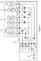
- Figure 4 shows the configuration of the manifold when the controller determines that there is a leak in the therapeutic mattress 104.
- the solenoid valve 220 has isolated the bottom mattress 106 from the therapeutic mattress 104.
- the solenoid valves 222, 224, 226 and 230 have been opened to atmosphere to enable the therapeutic mattress to be deflated to prevent an uneven support surface from developing and harming the person being supported on the mattress.
- Figure 5 shows the configuration of the manifold when the controller determines that there is a leak in the bottom support mattress 106.
- the solenoid valves 216 and 218 have isolated the bottom mattress 106 from the therapeutic mattress 104 and from the compressor. Further, those solenoid valves 216 and 218 have been opened to atmosphere to enable the bottom mattress 106 to be deflated to prevent an uneven support surface from developing and harming the person being supported on the mattress.
- the layer not having the leak is pneumatically coupled to the compressor and regulated to a pressure such that the person being supported is not allowed to come into contact with the bed frame, or the like, supporting the support device.
- pressure sensor 214 is used to monitor and regulate the pressure in the top, therapeutic, layer
- pressure sensor 234 is used to monitor and regulate the pressure in the bottom, support, layer.
- Figure 6 shows the support device system as a whole.
- the support device 100 is coupled pneumatically to the manifold 200 by hoses 600
- the compressor 202 is pneumatically coupled to the manifold 200
- the controller 602 is electrically coupled to both the compressor 202 and the solenoid valves of the manifold 200.
- an alarm 604 is electrically coupled to the controller 602.
- the alarm 604 When a leak is detected as described above, the alarm 604 is activated to alert a healthcare professional and/or a maintenance technician that the support device 100 has developed a leak.
- the alarm may be visual and/or audible.
- the alarm 604 may be coupled to the support device 100 itself, to a bed or the like supporting the support device 100.
- a remote alarm may be provided.
- the remote alarm may be at a central location, such as a nurse station, or in a maintenance office, or the like.
- the controller may communicate with the alarm by a wireless or a wired communication connection.
- the wireless connection may be use a 802.11, Wi-Fi, protocol over a local area network (LAN), an infrared transmission protocol, such as an IrDA protocol, Bluetooth ® , or any other suitable wireless transmission method.
- the connection is a wired connection, the system may use any standard transmission protocol such as TCP/IP, RS232.
Abstract
Description
- The present invention relates to a pneumatic support device and control system for detecting air leaks in the support device. The support device finds application as a mattress for beds, and in particular for medical beds in healthcare facilities.
- Patient support devices are well-known. In particular, it is known to provide devices in the form of mattresses for supporting a body, in particular the body of a patient. Mattresses of this type may comprise a structure made up, at least in part, of a plurality of inflatable elements or cells suitable for being inflated with a fluid, in particular for being inflated with air. Such support devices and mattresses are conventionally used in healthcare beds and in wheelchairs or other healthcare seats, and that are made up of inflatable elements. The inflatable elements are generally in the form of substantially cylindrical sausage-shaped tubes that extend transversely relative to the longitudinal direction of the mattress and that are disposed side-by-side in the longitudinal direction of the mattress. Other arrangements are also known, and depend on the specific requirements of the support device.
- In a support device of this type, which can be used, in particular, as a mattress, each inflatable element is generally provided with an air feed orifice and with an air discharge orifice, which orifices are equipped with or communicate in a substantially leak-tight manner with at least one air feed means, e.g. via a solenoid valve that is itself connected to a pneumatic control device for controlling inflation of the inflatable elements of the mattress and for regulating the air pressures inside the elements.
- In practice, in order to fill or inflate one of the inflatable elements of the support device, air is fed into the element via its feed orifice until the necessary pressure is reached inside the inflatable element. Conversely, in order to empty or deflate one of the inflatable elements, or in order to adjust the pressure inside the element, the feed orifice is kept closed and the air is discharged via the discharge orifice provided for that purpose, and in some instances, also provided with a solenoid valve that is also controlled by the pneumatic control device for controlling inflation.
- Support devices of this type are used as mattresses for patient care because they make it possible to distribute appropriately the interface pressure, i.e. the pressure exerted locally by each point of the body on the surface of the mattress, as a function of the morphology and of the position of the patient.
- In particular, such mattresses make it possible, as a function of the number of inflatable elements implemented, to control individually the pressure, and therefore, the filling of the inflatable elements in different zones of the mattress so as to procure an appropriate distribution of interface pressure engaging each portion of the patient' s body, and so as to avoid or reduce the risks of bedsores forming in zones of the body that are at risk, such as the sacral zone and the heel zone, for example.
- In principle, ideal patient comfort and optimum blood circulation for avoiding bedsore formation or for reducing local pain in certain zones of the body that bear against the mattress are obtained when the bearing points of the body are redistributed over the surface of the mattress, i.e. when the pressure exerted by the various zones of the body on the mattress (which pressure is referred to as the "interface pressure") is substantially identical at all of the points of the surface of body that are in contact with the mattress and if, in addition, the surface area of the body that is contact with the mattress is as large as possible, which requires the degree to which the inflatable elements of the mattress are inflated under the various portions of the body to be adapted to control the depth to which the body penetrates into the various zones of the mattress. For this purpose, the air pressures inside the inflatable elements are distributed by controlling the filling/emptying of the elements in accordance with certain pre-established calculations based on, and as a function of, measurements taken with sensors in, on, or below the mattress, depending on the type of sensors implemented.
- Such sensors are known to the person skilled in the art and can measure the pressure exerted by the patient's body or the depth to which the patient's body penetrates into the given compartments of the mattress, as described, for example, in the Applicant's European Patent
EP 0 676 158 and in the Applicant's European PatentEP 1 056 372 . - Controlling and regulating filling/emptying of the inflatable elements via solenoid valves also makes it possible to obtain support devices that operate in an "alternating-pressure mode" in which certain inflatable elements of the support device that are uniformly distributed along the length thereof are inflated and deflated simultaneously and in alternation. For example, one in every two elements, or two in every three elements, or indeed one in every four elements, are deflated and re-inflated, and then the elements adjacent to the previously deflated and re-inflated compartments are deflated and re-inflated. Thus, each inflatable element of the support device is deflated/re-inflated in succession, one after another, thereby creating a sort of wave moving back and forth in the longitudinal direction of the support device and relieving the interface pressure locally, thereby locally facilitating blood circulation through the soft tissue at the interface with the surface of the support device.
- Currently, support devices, in particular mattresses, incorporating such inflatable elements are frequently made up of a first air mattress layer having a casing that is not elastic. This first layer having a thickness that is generally constant over the entire length of the mattress, forming a "bottom" mattress on which a second layer or "therapeutic" mattress is placed that is formed by juxtaposing inflatable elements that are welded (e.g., heat-sealed) or otherwise bonded together, and that are in the general shape of substantially cylindrical sausage-shaped tubes or cells extending in a direction perpendicular to the longitudinal direction of the mattress.
- Each of the zones of the therapeutic mattress is provided with solenoid valves and with pipes or tubes adapted to be connected to an inflation and regulation device that is generally independent from the bottom mattress.
- Such mattresses make it possible to assist in preventing, and in providing effective and increased treatment of bedsores and of other lesions or pain that develop as a result of patients being kept in the recumbent position and almost immobile for prolonged periods in hospital beds, in particular, by implementing cycles of alternately inflating and deflating the cells of the therapeutic mattress and by using inflation pressures for the cells that differ as a function of the various support zones for supporting the patient's body.
- However, such mattresses are susceptible to air leaks, such as those caused by a puncture. Where such an air leak occurs, without intervention, the patient's safety may be at risk. In the Applicant's US Patent
US 8,5898,893 B - Nevertheless, such a safety system still has drawbacks, and cannot mitigate the risk to the patient when there is a leak in the bottom mattress, nor can the system detect which portion of the therapeutic mattress is leaking. It is therefore an object of the present invention to provide a patient support device having an improved control and safety system which mitigates the drawbacks of known patient support devices.
- According to a first aspect of the present disclosure, there is provided a support device for supporting the body of a person. The support device comprises: a top layer comprising at least one individually inflatable cell, inflatable via a pneumatic inflation and pressure regulation device; a bottom layer, arranged to support the top layer, the bottom layer comprising at least one inflatable cell, inflatable via the pneumatic inflation and pressure regulation device; and a pneumatic inflation and pressure regulation device comprising a controller and a compressor, pneumatically coupled to the at least one inflatable cell of the top layer and to the at least one inflatable cell of the bottom layer via a manifold. The manifold comprises: a plurality of isolation valves configured to enable the top layer and the bottom layer to be isolated from each other and from the compressor; at least one exhaust valve pneumatically coupled to the top layer; and at least one exhaust valve pneumatically coupled to the bottom layer. The controller is configured to: determine if there is an air leak from the support device; upon determining an air leak: determine the layer which has the leak; isolate the layer which has the leak from the other layer and from the compressor; and open the exhaust valve to the layer which has the leak.
- Advantageously, controlling the system in this way enables a leak to be detected, located in a particular portion of the support device, and for the remaining operational portion of the support device to be used to ensure the person being supported on the support device is protected from harm. For example, where the support device is a mattress for a hospital bed, the system may reduce the probability of the patient developing bed sores due to coming into contact with the hard surface of the bed frame, or due to being supported in a non-ideal manner because one of the layers developing a leak.
- By opening the exhaust valve to the layer having the leak, the layer may exhaust to atmosphere, enabling it to deflate.
- In a preferred embodiment, the top layer comprises a plurality of individually inflatable cells. In this way, the top layer may be a therapeutic mattress. The bottom layer may also comprise a plurality of individually inflatable cells.
- Preferably, the controller is configured to determine the layer that has the leak by: isolating the top layer and the bottom layer from each other and from the compressor; determining the pressure difference in either the bottom layer or the top layer between a first time and a second time; if the pressure difference is greater than a threshold value, opening the exhaust valve coupled to the respective layer; and if the pressure difference is less than a threshold value, open the exhaust valve to the respective other layer.
- In this preferred embodiment, the support device further comprises a pressure sensor pneumatically coupled to the top layer or to the bottom layer, in dependence on which layer is having the pressure difference determined. A further pressure sensor may be pneumatically coupled to the respective other layer.
- Preferably, the controller is further configured to couple the compressor to the layer which does not have a leak.
- The controller may alternatively be configured to determine the layer that has the leak by: isolating the top layer and the bottom layer from each other and from the compressor; determining the pressure difference in both the bottom layer and the top layer between a first time and a second time; if the pressure difference is greater in the top layer, opening the exhaust valve coupled to the top layer; and if the pressure difference is greater in the bottom layer, opening the exhaust valve to the bottom layer.
- In this alternative embodiment, the support device preferably further comprises at least two pressure sensors, a first pressure sensor pneumatically coupled to the top layer and a second pressure sensor pneumatically coupled to the bottom layer.
- Preferably, the controller is further configured to activate an alarm. The alarm may be local to the support device, or may be remote from the support device. The alarm may be audible or visible or both audible and visible. Where the alarm is remote from the support device, an alarm signal may be transmitted to a remote monitoring station. The alarm signal may be transmitted by a wired connection or a wireless connection. For example, the wireless connection may be use a 802.11, Wi-Fi, protocol over a local area network (LAN), an infrared transmission protocol, such as an IrDA protocol, Bluetooth®, or any other suitable wireless transmission method. Where the connection is a wired connection, the system may use any standard transmission protocol such as TCP/IP, RS232.
- Preferably, the controller is further configured to: if the pressure difference is greater than the threshold value, couple the compressor to the bottom layer; and if the pressure difference is less than the threshold value, couple the compressor to the top layer. In this preferred embodiment, the controller is preferably further configured to regulate the pressure in the layer coupled to the compressor. The regulation pressure may be greater than the operating pressure of the layer. In this way, once the leak is detected, and the layer having the leak is detected, the air pressure in the layer without the leak can be regulated to ensure that the person being supported by the support device does not come into contact with a supporting frame which supports the supporting device.
- In the embodiment which enables the layer having the leak to be identified, the controller may be configured to indicate which layer has the leak. In this way, the controller can inform a maintenance technician, or the like, which layer the leak is in to increase the speed of repair. Where the system comprises a visible alarm, the visible alarm may provide the indication as to which layer has the leak.
- The controller may comprise a communication port for coupling with an external device, the communication port being adapted to communicate status information to the external device. For example, the external device may be a computer, terminal, PDA, smartphone, or the like utilised by a maintenance technician. The status information may comprise data relating to the layer in which the leak has been detected.
- Each of the isolation valves may be an electrically operated solenoid valve. Each of the electrically operated solenoid valves are operatively coupled to the controller.
- The manifold may comprise a further pressure sensor, pneumatically coupled to at least one of the inflatable cells of the top layer, the controller being configured to determine a pressure difference between a first time and a second time to determine whether there is a leak in the at least one inflatable cells of the top layer.
- One or more of the individual inflatable cells may each be pneumatically coupled to an isolation valve configured to isolate the respective inflatable cell from the other inflatable cells and from the compressor. By isolating the respective inflatable cells, the location of the leak may be more accurately determined. In this embodiment, each of the plurality of individually inflatable cells may be operatively coupled to a pressure sensor, such that the location of the leak may be determined. The information determined by the controller as to the location of the leak can then be used by the maintenance technician to repair the leak more quickly.
- According to a further aspect of the present invention, there is provided a method of controlling a support device, for supporting the body of a person, the support device comprising a top layer having at least one individually inflatable cell, a bottom layer having at least one inflatable cell and a pneumatic inflation and pressure regulation device comprising a compressor. The method comprises: determining if there is an air leak from the support device; upon determining an air leak: determining the layer which has a leak; isolating the layer which has the leak from the other layer and from the compressor, and opening the exhaust valve to the layer which has a leak.
- Advantageously, providing such a method enables a leak to be detected, located in a particular portion of the support device, and enables the remaining operational portion of the support device to be used to ensure the person being supported on the support device is protected from harm. For example, where the support device is a mattress for a hospital bed, the method may reduce the probability of the patient developing bed sores due to coming into contact with the hard surface of the bed frame, or due to being supported in a non-ideal manner because one of the layers developing a leak.
- Preferably, the step of determining the layer that has the leak, comprises: isolating the top layer and the bottom layer from each other and from the compressor; determining the pressure difference in either the bottom layer or the top layer between a first time and a second time; if the pressure difference is greater than a threshold value, opening the exhaust valve coupled to the respective layer; and if the pressure difference is less than a threshold value, open the exhaust valve to the respective other layer.
- Alternatively, the step of determining the layer that has the leak, comprises: isolating the top layer and the bottom layer from each other and from the compressor; determining the pressure difference in both the bottom layer and the top layer between a first time and a second time; if the pressure difference is greater in the top layer, opening the exhaust valve coupled to the top layer; and if the pressure difference is greater in the bottom layer, opening the exhaust valve to the bottom layer.
- In a yet further alternative, the step of determining the layer that has the leak comprises: isolating the top layer from the bottom layer; isolating one of the top layer and the bottom layer from the compressor; regulating the pressure in the remaining layer pneumatically coupled to the compressor; determining whether the pressure in said layer can be regulated at the operating pressure; if the pressure can be regulated, the leak is in the other layer; if the pressure can not be regulated, the leak is in the layer coupled to the compressor. In this embodiment, if the leak is in the other layer, the configuration is maintained. If the leak is in the layer coupled to the compressor, the layer is isolated from the compressor and exhausted to atmosphere, and the other layer is pneumatically coupled to the compressor and regulated at a pressure.
- The method preferably further comprises activating an alarm upon determining an air leak. The alarm may be local to the support device, or may be remote from the support device. The alarm may be audible or visible or both audible and visible. Where the alarm is remote from the support device, the method may comprise transmitting the alarm signal to a remote monitoring station. The alarm signal may be transmitted by a wired connection or a wireless connection. For example, the wireless connection may be use a 802.11, Wi-Fi, protocol over a local area network (LAN), an infrared transmission protocol, such as an IrDA protocol, Bluetooth®, or any other suitable wireless transmission method. Where the connection is a wired connection, the system may use any standard transmission protocol such as TCP/IP, RS232.
- The step of determining if there is an air leak from the support device preferably comprises: monitoring the continuous activation time of the compressor to maintain an operating pressure; if the activation time is greater than a threshold value, determining that there is a leak. Operating the support device in this way minimises the requirement for additional hardware, while still providing the advantage of determining whether there is a leak.
- The threshold value for the activation time may be about 5 minutes, about 8 minutes, about 10 minutes, about 15 minutes, or longer. In a preferred embodiment, the threshold value for the activation time is about 10 minutes.
- The step of determining if there is a leak may alternatively comprise: monitoring the pressure in the top layer and in the bottom layer while the compressor is activated; if the pressure in either layer does not increase within a predetermined time interval, determine that there is a leak. In this embodiment, the pressure may be monitored in each layer separately, such that the layer having the leak may be determined, by corresponding the increase in pressure with the layer which does not have a leak. In this embodiment, the method may comprise determining there is a leak if the pressure does not increase by a predetermined amount within the predetermined time interval.
- The step of determining if there is a leak may alternatively comprise monitoring the pressure in the top layer and the bottom layer, wherein it is determined that there is a leak if the internal pressure of either layer drops below a predetermined threshold. In one example, the predetermined threshold may be between about 5 mbar and about 30 mbar, and in one preferred example the predetermined threshold may be about 10 mbar.
- In one embodiment, upon determining an air leak: if the pressure difference is greater than the threshold value, couple the compressor to the bottom layer; and if the pressure difference is less than the threshold value, couple the compressor to the top layer. In this embodiment, upon determining an air leak the pressure in the layer coupled to the compressor is regulated. Preferably, the regulation pressure is greater than the operating pressure of the layer. By regulating the pressure to above the operating pressure, the support device prevents the person being supported from contacting a bed frame, or the like, underneath the support device.
- Where the pressure difference is determined between a first time and a second time, the time difference between the first time and the second time may be between about 30 seconds and about 180 seconds, preferably between about 45 seconds and about 90 seconds. In one particular embodiment, the time difference is about 60 seconds.
- In the embodiment which enables the layer having the leak to be identified, the method may further comprise indicating which layer has the leak. In this way, the method informs a maintenance technician, or the like, which layer the leak is in to increase the speed of repair. Where the method comprises activating a visible alarm, the visible alarm may provide the indication as to which layer has the leak.
- The method may comprise communicating status information to a maintenance technician via a communications port on the support device. The status information may comprise data relating to the layer in which the leak has been detected.
- The manifold may comprise a further pressure sensor, pneumatically coupled to at least one of the inflatable cells of the top layer, the method further comprising determining a pressure difference between a first time and a second time to determine whether there is a leak in the at least one inflatable cells of the top layer.
- One or more of the individual inflatable cells may each be pneumatically coupled to an isolation valve configured to isolate the respective inflatable cell from the other inflatable cells and from the compressor. By isolating the respective inflatable cells, the location of the leak may be more accurately determined. In this embodiment, each of the plurality of individually inflatable cells may be operatively coupled to a pressure sensor, such that the location of the leak may be determined. The information determined by the method as to the location of the leak can then be used by the maintenance technician to repair the leak more quickly.
- Any feature in one aspect of the invention may be applied to other aspects of the invention, in any appropriate combination. In particular, method aspects may be applied to apparatus aspects, and vice versa. Furthermore, any, some and/or all features in one aspect can be applied to any, some and/or all features in any other aspect, in any appropriate combination.
- It should also be appreciated that particular combinations of the various features described and defined in any aspects of the invention can be implemented and/or supplied and/or used independently.
- The invention will be further described, by way of example only, with reference to the accompanying drawings in which:
-
Figure 1 shows a schematic view of a support device having a therapeutic mattress and an under mattress; -
Figure 2 shows a schematic view of a manifold for use with the support device ofFigure 1 ; -
Figure 3 shows a leak detection configuration of the manifold ofFigure 2 ; -
Figure 4 shows a configuration of the manifold ofFigure 2 when a leak is detected in the therapeutic mattress; -
Figure 5 shows a configuration of the manifold ofFigure 2 when a leak is detected in the under mattress; and -
Figure 6 shows a schematic view of the support device system. -
Figure 1 shows a schematic view of asupport device 100. Thesupport device 100 of forms a mattress that is suitable for supporting the body of an individual, in particular of a patient, and that comprises aremovable cover 102 containing a top layer formed by atherapeutic mattress 104 resting on a bottom layer formed by a bottom support mattress 106. The therapeutic mattress is made up of inflatable air elements orcells device 100. The inflatable cells are distributed into three adjacent support zones for supporting respective main portions of the body of an individual who is recumbent on thedevice 100, namely: afirst zone 114 for supporting the torso and the head; asecond zone 116 for supporting the legs and the feet; and athird zone 118 interposed between thezones - In a known manner, regardless of whether it is in the
central zone 118 or in one of thezones inflatable cells support zone 116 and in alignment with the bottom mattress 106. Alternatively, the pneumatic inflation and pressure regulation device can be entirely external to the support device. - In some embodiments of the device, the inflatable cells of the top layer are made of a thermoplastic polymer material, in particular a material based on polyurethane (PU). Such a material offers the characteristics of being both flexible and strong and, by being thermoplastic, of being sensitive to human body heat, thereby enhancing the comfort and the flexibility of the support procured for an individual on the mattress.
- The bottom mattress 106 of the device is, like the
therapeutic mattress 104, made up of interconnectedinflatable cells 120 suitable for being connected to the pneumatic inflation and pressure regulation device. Theinflatable cells 120 of the bottom layer 106 of themattress 100 may be made of a material of flexibility and of heat-sensitivity lower than those of the material of which the inflatable cells of the therapeutic mattress are formed, so that an unchanging geometrical shape is maintained. - The casing of the
inflatable cells 120 of thebottom mattress 104 can be made of a woven fabric, such as a polyurethane-coated Nylon® fabric. The alternation of materials, such as polyurethane for thetherapeutic mattress 104 and polyurethane-coated Nylon® for the bottom mattress 106, makes it possible for the therapeutic mattress to offer the desirable comfort and for the bottom mattress to maintain a stable geometrical shape. - The air cells in the therapeutic mattress may be secured to one another and formed by flat butt welding (e.g., heat-sealing) together two sheets of polyurethane, along weld lines that are mutually parallel.
- Each air cell may be provided with a plastic connector making it possible to connect a pneumatic pipe or tube communicating with other air cells of the
same segment - This configuration for hydraulically linking together the various cells guarantees mechanical stability for all of the individualized cells of each zone. The
therapeutic mattress 104 comprising the twosegments central zone 118 is held together physically by plastics press studs on the outer casing, which press studs are placed in such a manner as to guarantee that thetherapeutic mattress 104 is held together mechanically with effective strength while also being releasable. The plastics press studs make disassembly possible in the event that thetherapeutic mattress 104 is replaced in full, or in part, by replacing the segment(s) 114 and/or 116 and/or thecentral zone 118. - The air pressures within the cells of the
various support zones therapeutic mattress 104 may be regulated by the pneumatic inflation and regulation device in an alternating low-pressure mode as a function of the information received from a morphology sensor. - The
support device 100 is pneumatically coupled to a manifold and pneumatic inflation and pressure regulation device. The manifold 200 and pneumatic inflation andpressure regulation device 202 are shown inFigure 2 pneumatically coupled to thesupport device 100. The manifold comprises a plurality ofcoupling ports support device 100 to themanifold 200. The manifold 200 further comprises a plurality ofcoupling ports pressure regulation device 202, apressure relief valve 208, equipment used by a technician duringmaintenance pressure sensor 214 respectively. The manifold also comprises a plurality ofsolenoid valves pressure regulation device 202. Each solenoid valve is configured to enable exhaust to atmosphere. - The
solenoid valve 215 is configured to isolate the support device from the pneumatic inflation and pressure regulation device, and to couple the pneumatic inflation and pressure regulation device to a micro-climate management (MCM)cover 232. TheMCM 232 cover may be provided on top of thesupport device 100 to regulate the temperature and moisture adjacent the person being supported by thedevice 100. - The
solenoid valve 220 is configured to isolate the under, bottom support, mattress 106.Solenoid valves - The
solenoid valves central zone 118 of thetherapeutic layer 104. This enables the zone to be exhausted in the event of a leak. - The
solenoid valve 226 enables theheel zone 116 to be exhausted to atmosphere in the event a leak is detected. - The
solenoid valve 228 enables theheel zone 116 to be isolated from the pneumatic inflation and pressure regulation device, and from other portions of the support device. - The
solenoid valve 230 enables some or all of the inflatable cells of the support device to be exhausted to atmosphere in dependence on the configuration of the other of the solenoid valves. This can enable the zones to be exhausted in the event of a leak or for generally exhausting the mattress. - As can also be seen from
Figure 2 , the bottom support mattress 106 is provided with apressure sensor 234 for determining the air pressure therein. Apressure relief valve 236 is pneumatically coupled to thehead zone 114 of thetherapeutic mattress 104 to prevent the therapeutic mattress from being over-inflated which may cause damage. Thepressure relief valve 208 prevents the bottom support mattress 106 from being over-inflated which may cause damage. - In use, the manifold and pneumatic inflation and pressure regulation device are controlled to pressurise the bottom support mattress and the therapeutic mattress as required, and as described above. In addition to the standard control method, the controller is configured to monitor whether either of the
therapeutic layer 104 or the bottom support layer 106 develop an air leak. - The controller is configured to: determine if there is an air leak from the support device; upon determining an air leak: isolate the
top layer 104 and the bottom layer 106 from each other and from thecompressor 202 by closingsolenoid valves pressure sensor 234; if the pressure difference is greater than a threshold value, open thesolenoid exhaust valves therapeutic mattress 104 is exhausted to atmosphere it is ensured that it is isolated from thebottom layer 104 by closingsolenoid valve 220. The configuration of the manifold when determining whether there is a leak is shown inFigure 3 . - The time difference between taking the first pressure reading and the second pressure reading may be about 60 seconds.
- Controlling the system in this way enables a leak to be detected, located in a particular portion of the support device, and for the remaining operational portion of the support device to be used to ensure the person being supported on the support device is protected from harm. For example, where the support device is a mattress for a hospital bed, the system may reduce the probability of the patient developing bed sores due to coming into contact with the hard surface of the bed frame, or due to being supported in a non-ideal manner because one of the layers developing a leak.
- Alternatively, or in addition, to determine whether there is a leak the controller is configured to monitor the continuous activation time of the compressor of the pneumatic inflation and
pressure regulation device 202. If the continuous activation time is greater than a threshold, for example 10 minutes, the controller determines that there is an air leak. At this point, the controller then proceeds to configure the manifold as described above to determine in which layer of thesupport device 100 the leak is. -
Figure 4 shows the configuration of the manifold when the controller determines that there is a leak in thetherapeutic mattress 104. As can be seen, thesolenoid valve 220 has isolated the bottom mattress 106 from thetherapeutic mattress 104. Further, thesolenoid valves -
Figure 5 shows the configuration of the manifold when the controller determines that there is a leak in the bottom support mattress 106. As can be seen, thesolenoid valves therapeutic mattress 104 and from the compressor. Further, thosesolenoid valves - In
Figures 4 and5 , once the leak is detected, and the layer having the leak is determined, the layer not having the leak is pneumatically coupled to the compressor and regulated to a pressure such that the person being supported is not allowed to come into contact with the bed frame, or the like, supporting the support device. In this example,pressure sensor 214 is used to monitor and regulate the pressure in the top, therapeutic, layer, andpressure sensor 234 is used to monitor and regulate the pressure in the bottom, support, layer. -
Figure 6 shows the support device system as a whole. As can be seen, thesupport device 100 is coupled pneumatically to the manifold 200 byhoses 600, thecompressor 202 is pneumatically coupled to the manifold 200 and thecontroller 602 is electrically coupled to both thecompressor 202 and the solenoid valves of themanifold 200. In addition, analarm 604 is electrically coupled to thecontroller 602. - When a leak is detected as described above, the
alarm 604 is activated to alert a healthcare professional and/or a maintenance technician that thesupport device 100 has developed a leak. The alarm may be visual and/or audible. Thealarm 604 may be coupled to thesupport device 100 itself, to a bed or the like supporting thesupport device 100. Alternatively, or in addition a remote alarm may be provided. The remote alarm may be at a central location, such as a nurse station, or in a maintenance office, or the like. - Where the alarm is remote, the controller may communicate with the alarm by a wireless or a wired communication connection. For example, the wireless connection may be use a 802.11, Wi-Fi, protocol over a local area network (LAN), an infrared transmission protocol, such as an IrDA protocol, Bluetooth®, or any other suitable wireless transmission method. Where the connection is a wired connection, the system may use any standard transmission protocol such as TCP/IP, RS232.
Claims (15)
- A support device for supporting the body of a person, the support device comprising:a top layer comprising at least one individually inflatable cell, inflatable via a pneumatic inflation and pressure regulation device;a bottom layer, arranged to support the top layer, the bottom layer comprising a at least one inflatable cell, inflatable via the pneumatic inflation and pressure regulation device; anda pneumatic inflation and pressure regulation device comprising a controller and a compressor, pneumatically coupled to the at least one inflatable cell of the top layer and to the at least one inflatable cell of the bottom layer via a manifold,wherein, the manifold comprises:a plurality of isolation valves configured to enable the top layer and the bottom layer to be isolated from each other and from the compressor;at least one exhaust valve pneumatically coupled to the top layer; andat least one exhaust valve pneumatically coupled to the bottom layer;and wherein, the controller is configured to:determine if there is an air leak from the support device;upon determining an air leak:determine the layer which has a leak;isolate the layer which has the leak from the other layer and from the compressor; andopen the exhaust valve to the layer which has the leak.
- A support device according to Claim 1, wherein the controller is configured to determine the layer that has the leak by:isolating the top layer and the bottom layer from each other and from the compressor;determining the pressure difference in either the bottom layer or the top layer between a first time and a second time;if the pressure difference is greater than a threshold value, opening the exhaust valve coupled to the respective layer; andif the pressure difference is less than a threshold value, open the exhaust valve to the respective other layer.
- A support device according to Claim 1, wherein the controller is configured to determine the layer that has the leak by:isolating the top layer and the bottom layer from each other and from the compressor;determining the pressure difference in both the bottom layer and the top layer between a first time and a second time;if the pressure difference is greater in the top layer, opening the exhaust valve coupled to the top layer; andif the pressure difference is greater in the bottom layer, opening the exhaust valve to the bottom layer.
- A support device according to Claim 1, 2 or 3, wherein the controller is further configured to activate an alarm when a leak is detected.
- A support device according to any of Claims 1 to 4, wherein the controller is further configured to:couple the compressor to the layer which does not have a leak.
- A support device according to Claim 5, wherein the controller is further configured to regulate the pressure in the layer coupled to the compressor.
- A support device according to any of the preceding claims, one or more of the individual inflatable cells each being pneumatically coupled to an isolation valve configured to isolate the respective inflatable cell from the other inflatable cells and from the compressor.
- A method of controlling a support device, for supporting the body of a person, the support device comprising a top layer having at least one individually inflatable cell, a bottom layer having at least one inflatable cell and a pneumatic inflation and pressure regulation device comprising a compressor, the method comprising:determining if there is an air leak from the support device;upon determining an air leak:determine the layer which has a leak;isolate the layer which has the leak from the other layer and from the compressor, andopen the exhaust valve to the layer which has a leak.
- A method according to Claim 8, wherein the step of determining the layer that has the leak, comprises:isolating the top layer and the bottom layer from each other and from the compressor;determining the pressure difference in either the bottom layer or the top layer between a first time and a second time;if the pressure difference is greater than a threshold value, opening the exhaust valve coupled to the respective layer; andif the pressure difference is less than a threshold value, open the exhaust valve to the respective other layer.
- A method according to Claim 8, wherein the step of determining the layer that has the leak, comprises:isolating the top layer and the bottom layer from each other and from the compressor;determining the pressure difference in both the bottom layer and the top layer between a first time and a second time;if the pressure difference is greater in the top layer, opening the exhaust valve coupled to the top layer; andif the pressure difference is greater in the bottom layer, opening the exhaust valve to the bottom layer.
- A method according to Claim 9 or 10, further comprising activating an alarm upon determining an air leak.
- A method according to Claim 9 or 10, wherein the step of determining if there is an air leak from the support device, comprises:monitoring the continuous activation time of the compressor to maintain an operating pressure;if the activation time is greater than a threshold value, determining that there is a leak.
- A method according to Claim 9, 10 or 11, wherein, upon determining an air leak:if the pressure difference is greater than the threshold value, couple the compressor to the bottom layer; andif the pressure difference is less than the threshold value, couple the compressor to the top layer.
- A method according to Claim 12, wherein, upon determining an air leak regulating the pressure in the layer coupled to the compressor.
- A method according to any of Claims 9 to 14, wherein the time difference between the first time and the second time is between about 30 seconds and about 180 seconds, preferably between about 45 seconds and about 90 seconds.
Priority Applications (1)
| Application Number | Priority Date | Filing Date | Title |
|---|---|---|---|
| EP16305418.2A EP3228294B1 (en) | 2016-04-08 | 2016-04-08 | Pneumatic support device and control system |
Applications Claiming Priority (1)
| Application Number | Priority Date | Filing Date | Title |
|---|---|---|---|
| EP16305418.2A EP3228294B1 (en) | 2016-04-08 | 2016-04-08 | Pneumatic support device and control system |
Publications (2)
| Publication Number | Publication Date |
|---|---|
| EP3228294A1 true EP3228294A1 (en) | 2017-10-11 |
| EP3228294B1 EP3228294B1 (en) | 2019-03-13 |
Family
ID=55745718
Family Applications (1)
| Application Number | Title | Priority Date | Filing Date |
|---|---|---|---|
| EP16305418.2A Active EP3228294B1 (en) | 2016-04-08 | 2016-04-08 | Pneumatic support device and control system |
Country Status (1)
| Country | Link |
|---|---|
| EP (1) | EP3228294B1 (en) |
Cited By (1)
| Publication number | Priority date | Publication date | Assignee | Title |
|---|---|---|---|---|
| EP3698764A1 (en) | 2019-02-22 | 2020-08-26 | Hill-Rom Services, Inc. | Mattress with valve system |
Citations (7)
| Publication number | Priority date | Publication date | Assignee | Title |
|---|---|---|---|---|
| WO1986006624A1 (en) * | 1985-05-10 | 1986-11-20 | Mediscus Products Limited | Patient support appliances |
| EP0676158A1 (en) | 1994-04-06 | 1995-10-11 | Support Systems International Industries | Method and device for supporting the body of a patient allowing controlled sagging |
| GB2327874A (en) * | 1997-08-09 | 1999-02-10 | Huntleigh Technology Plc | inflatable support |
| FR2774573A1 (en) * | 1998-02-09 | 1999-08-13 | Support Systems International | Dynamic and automatic control of pressure in support used particularly for patients, very compact and economical with no requirement for inductive or capacitative detectors |
| EP2005929A1 (en) * | 2007-06-18 | 2008-12-24 | Hill-Rom Industries S.A. | Matress support device comprising a heterogeneous inflatable structure |
| WO2011006093A1 (en) * | 2009-07-09 | 2011-01-13 | Kreg Medical, Inc. | Adjustable therapeutic mattress |
| US8598893B2 (en) | 2009-06-05 | 2013-12-03 | Hill-Rom Industries Sa | Pressure sensor comprising a capacitive cell and support device comprising said sensor |
-
2016
- 2016-04-08 EP EP16305418.2A patent/EP3228294B1/en active Active
Patent Citations (8)
| Publication number | Priority date | Publication date | Assignee | Title |
|---|---|---|---|---|
| WO1986006624A1 (en) * | 1985-05-10 | 1986-11-20 | Mediscus Products Limited | Patient support appliances |
| EP0676158A1 (en) | 1994-04-06 | 1995-10-11 | Support Systems International Industries | Method and device for supporting the body of a patient allowing controlled sagging |
| GB2327874A (en) * | 1997-08-09 | 1999-02-10 | Huntleigh Technology Plc | inflatable support |
| FR2774573A1 (en) * | 1998-02-09 | 1999-08-13 | Support Systems International | Dynamic and automatic control of pressure in support used particularly for patients, very compact and economical with no requirement for inductive or capacitative detectors |
| EP1056372A1 (en) | 1998-02-09 | 2000-12-06 | Hill-Rom Industries S.A. | Method and apparatus for supporting an object requiring support, in particular a patient's body with integrated system for dynamic and automatic pressure equalisation |
| EP2005929A1 (en) * | 2007-06-18 | 2008-12-24 | Hill-Rom Industries S.A. | Matress support device comprising a heterogeneous inflatable structure |
| US8598893B2 (en) | 2009-06-05 | 2013-12-03 | Hill-Rom Industries Sa | Pressure sensor comprising a capacitive cell and support device comprising said sensor |
| WO2011006093A1 (en) * | 2009-07-09 | 2011-01-13 | Kreg Medical, Inc. | Adjustable therapeutic mattress |
Cited By (1)
| Publication number | Priority date | Publication date | Assignee | Title |
|---|---|---|---|---|
| EP3698764A1 (en) | 2019-02-22 | 2020-08-26 | Hill-Rom Services, Inc. | Mattress with valve system |
Also Published As
| Publication number | Publication date |
|---|---|
| EP3228294B1 (en) | 2019-03-13 |
Similar Documents
| Publication | Publication Date | Title |
|---|---|---|
| US20230346616A1 (en) | Support apparatus, system and method | |
| EP0759717B1 (en) | Improvements in and relating to beds and apparatus for use therewith | |
| EP2289476B1 (en) | Lateral tilt device | |
| EP1987806B1 (en) | Low air loss moisture control mattress overlay | |
| US6943694B1 (en) | Bottoming sensor | |
| US8296887B2 (en) | Resilient material/air bladder system | |
| US20110163885A1 (en) | Adjustable therapeutic mattress | |
| EP2731567A2 (en) | Patient/invalid handling support | |
| EP1871324A2 (en) | Multicompartmented air mattress | |
| US20150013073A1 (en) | Therapy control for patient support system | |
| US20010034908A1 (en) | Mattress | |
| US8037563B2 (en) | Multiple air source mattress control system | |
| WO2011006093A1 (en) | Adjustable therapeutic mattress | |
| EP3228294B1 (en) | Pneumatic support device and control system | |
| WO2014080196A2 (en) | Mattress arrangement | |
| GB2387114A (en) | Patient support structures |
Legal Events
| Date | Code | Title | Description |
|---|---|---|---|
| PUAI | Public reference made under article 153(3) epc to a published international application that has entered the european phase |
Free format text: ORIGINAL CODE: 0009012 |
|
| STAA | Information on the status of an ep patent application or granted ep patent |
Free format text: STATUS: THE APPLICATION HAS BEEN PUBLISHED |
|
| AK | Designated contracting states |
Kind code of ref document: A1 Designated state(s): AL AT BE BG CH CY CZ DE DK EE ES FI FR GB GR HR HU IE IS IT LI LT LU LV MC MK MT NL NO PL PT RO RS SE SI SK SM TR |
|
| AX | Request for extension of the european patent |
Extension state: BA ME |
|
| STAA | Information on the status of an ep patent application or granted ep patent |
Free format text: STATUS: REQUEST FOR EXAMINATION WAS MADE |
|
| 17P | Request for examination filed |
Effective date: 20180411 |
|
| RBV | Designated contracting states (corrected) |
Designated state(s): AL AT BE BG CH CY CZ DE DK EE ES FI FR GB GR HR HU IE IS IT LI LT LU LV MC MK MT NL NO PL PT RO RS SE SI SK SM TR |
|
| GRAP | Despatch of communication of intention to grant a patent |
Free format text: ORIGINAL CODE: EPIDOSNIGR1 |
|
| STAA | Information on the status of an ep patent application or granted ep patent |
Free format text: STATUS: GRANT OF PATENT IS INTENDED |
|
| RIC1 | Information provided on ipc code assigned before grant |
Ipc: A61G 7/057 20060101AFI20180814BHEP |
|
| INTG | Intention to grant announced |
Effective date: 20180919 |
|
| GRAS | Grant fee paid |
Free format text: ORIGINAL CODE: EPIDOSNIGR3 |
|
| GRAA | (expected) grant |
Free format text: ORIGINAL CODE: 0009210 |
|
| STAA | Information on the status of an ep patent application or granted ep patent |
Free format text: STATUS: THE PATENT HAS BEEN GRANTED |
|
| AK | Designated contracting states |
Kind code of ref document: B1 Designated state(s): AL AT BE BG CH CY CZ DE DK EE ES FI FR GB GR HR HU IE IS IT LI LT LU LV MC MK MT NL NO PL PT RO RS SE SI SK SM TR |
|
| REG | Reference to a national code |
Ref country code: GB Ref legal event code: FG4D |
|
| REG | Reference to a national code |
Ref country code: CH Ref legal event code: EP Ref country code: AT Ref legal event code: REF Ref document number: 1106686 Country of ref document: AT Kind code of ref document: T Effective date: 20190315 |
|
| REG | Reference to a national code |
Ref country code: IE Ref legal event code: FG4D |
|
| REG | Reference to a national code |
Ref country code: DE Ref legal event code: R096 Ref document number: 602016010998 Country of ref document: DE |
|
| REG | Reference to a national code |
Ref country code: NL Ref legal event code: MP Effective date: 20190313 |
|
| REG | Reference to a national code |
Ref country code: LT Ref legal event code: MG4D |
|
| PG25 | Lapsed in a contracting state [announced via postgrant information from national office to epo] |
Ref country code: SE Free format text: LAPSE BECAUSE OF FAILURE TO SUBMIT A TRANSLATION OF THE DESCRIPTION OR TO PAY THE FEE WITHIN THE PRESCRIBED TIME-LIMIT Effective date: 20190313 Ref country code: LT Free format text: LAPSE BECAUSE OF FAILURE TO SUBMIT A TRANSLATION OF THE DESCRIPTION OR TO PAY THE FEE WITHIN THE PRESCRIBED TIME-LIMIT Effective date: 20190313 Ref country code: NO Free format text: LAPSE BECAUSE OF FAILURE TO SUBMIT A TRANSLATION OF THE DESCRIPTION OR TO PAY THE FEE WITHIN THE PRESCRIBED TIME-LIMIT Effective date: 20190613 Ref country code: FI Free format text: LAPSE BECAUSE OF FAILURE TO SUBMIT A TRANSLATION OF THE DESCRIPTION OR TO PAY THE FEE WITHIN THE PRESCRIBED TIME-LIMIT Effective date: 20190313 |
|
| PG25 | Lapsed in a contracting state [announced via postgrant information from national office to epo] |
Ref country code: BG Free format text: LAPSE BECAUSE OF FAILURE TO SUBMIT A TRANSLATION OF THE DESCRIPTION OR TO PAY THE FEE WITHIN THE PRESCRIBED TIME-LIMIT Effective date: 20190613 Ref country code: HR Free format text: LAPSE BECAUSE OF FAILURE TO SUBMIT A TRANSLATION OF THE DESCRIPTION OR TO PAY THE FEE WITHIN THE PRESCRIBED TIME-LIMIT Effective date: 20190313 Ref country code: RS Free format text: LAPSE BECAUSE OF FAILURE TO SUBMIT A TRANSLATION OF THE DESCRIPTION OR TO PAY THE FEE WITHIN THE PRESCRIBED TIME-LIMIT Effective date: 20190313 Ref country code: NL Free format text: LAPSE BECAUSE OF FAILURE TO SUBMIT A TRANSLATION OF THE DESCRIPTION OR TO PAY THE FEE WITHIN THE PRESCRIBED TIME-LIMIT Effective date: 20190313 Ref country code: GR Free format text: LAPSE BECAUSE OF FAILURE TO SUBMIT A TRANSLATION OF THE DESCRIPTION OR TO PAY THE FEE WITHIN THE PRESCRIBED TIME-LIMIT Effective date: 20190614 Ref country code: LV Free format text: LAPSE BECAUSE OF FAILURE TO SUBMIT A TRANSLATION OF THE DESCRIPTION OR TO PAY THE FEE WITHIN THE PRESCRIBED TIME-LIMIT Effective date: 20190313 |
|
| REG | Reference to a national code |
Ref country code: AT Ref legal event code: MK05 Ref document number: 1106686 Country of ref document: AT Kind code of ref document: T Effective date: 20190313 |
|
| PG25 | Lapsed in a contracting state [announced via postgrant information from national office to epo] |
Ref country code: AL Free format text: LAPSE BECAUSE OF FAILURE TO SUBMIT A TRANSLATION OF THE DESCRIPTION OR TO PAY THE FEE WITHIN THE PRESCRIBED TIME-LIMIT Effective date: 20190313 Ref country code: PT Free format text: LAPSE BECAUSE OF FAILURE TO SUBMIT A TRANSLATION OF THE DESCRIPTION OR TO PAY THE FEE WITHIN THE PRESCRIBED TIME-LIMIT Effective date: 20190713 Ref country code: SK Free format text: LAPSE BECAUSE OF FAILURE TO SUBMIT A TRANSLATION OF THE DESCRIPTION OR TO PAY THE FEE WITHIN THE PRESCRIBED TIME-LIMIT Effective date: 20190313 Ref country code: IT Free format text: LAPSE BECAUSE OF FAILURE TO SUBMIT A TRANSLATION OF THE DESCRIPTION OR TO PAY THE FEE WITHIN THE PRESCRIBED TIME-LIMIT Effective date: 20190313 Ref country code: EE Free format text: LAPSE BECAUSE OF FAILURE TO SUBMIT A TRANSLATION OF THE DESCRIPTION OR TO PAY THE FEE WITHIN THE PRESCRIBED TIME-LIMIT Effective date: 20190313 Ref country code: RO Free format text: LAPSE BECAUSE OF FAILURE TO SUBMIT A TRANSLATION OF THE DESCRIPTION OR TO PAY THE FEE WITHIN THE PRESCRIBED TIME-LIMIT Effective date: 20190313 Ref country code: CZ Free format text: LAPSE BECAUSE OF FAILURE TO SUBMIT A TRANSLATION OF THE DESCRIPTION OR TO PAY THE FEE WITHIN THE PRESCRIBED TIME-LIMIT Effective date: 20190313 Ref country code: ES Free format text: LAPSE BECAUSE OF FAILURE TO SUBMIT A TRANSLATION OF THE DESCRIPTION OR TO PAY THE FEE WITHIN THE PRESCRIBED TIME-LIMIT Effective date: 20190313 |
|
| PG25 | Lapsed in a contracting state [announced via postgrant information from national office to epo] |
Ref country code: PL Free format text: LAPSE BECAUSE OF FAILURE TO SUBMIT A TRANSLATION OF THE DESCRIPTION OR TO PAY THE FEE WITHIN THE PRESCRIBED TIME-LIMIT Effective date: 20190313 Ref country code: SM Free format text: LAPSE BECAUSE OF FAILURE TO SUBMIT A TRANSLATION OF THE DESCRIPTION OR TO PAY THE FEE WITHIN THE PRESCRIBED TIME-LIMIT Effective date: 20190313 |
|
| REG | Reference to a national code |
Ref country code: CH Ref legal event code: PL |
|
| REG | Reference to a national code |
Ref country code: DE Ref legal event code: R097 Ref document number: 602016010998 Country of ref document: DE |
|
| REG | Reference to a national code |
Ref country code: BE Ref legal event code: MM Effective date: 20190430 |
|
| REG | Reference to a national code |
Ref country code: GB Ref legal event code: 732E Free format text: REGISTERED BETWEEN 20191128 AND 20191204 |
|
| PG25 | Lapsed in a contracting state [announced via postgrant information from national office to epo] |
Ref country code: IS Free format text: LAPSE BECAUSE OF FAILURE TO SUBMIT A TRANSLATION OF THE DESCRIPTION OR TO PAY THE FEE WITHIN THE PRESCRIBED TIME-LIMIT Effective date: 20190713 Ref country code: AT Free format text: LAPSE BECAUSE OF FAILURE TO SUBMIT A TRANSLATION OF THE DESCRIPTION OR TO PAY THE FEE WITHIN THE PRESCRIBED TIME-LIMIT Effective date: 20190313 Ref country code: LU Free format text: LAPSE BECAUSE OF NON-PAYMENT OF DUE FEES Effective date: 20190408 |
|
| PLBE | No opposition filed within time limit |
Free format text: ORIGINAL CODE: 0009261 |
|
| STAA | Information on the status of an ep patent application or granted ep patent |
Free format text: STATUS: NO OPPOSITION FILED WITHIN TIME LIMIT |
|
| PG25 | Lapsed in a contracting state [announced via postgrant information from national office to epo] |
Ref country code: MC Free format text: LAPSE BECAUSE OF FAILURE TO SUBMIT A TRANSLATION OF THE DESCRIPTION OR TO PAY THE FEE WITHIN THE PRESCRIBED TIME-LIMIT Effective date: 20190313 Ref country code: DK Free format text: LAPSE BECAUSE OF FAILURE TO SUBMIT A TRANSLATION OF THE DESCRIPTION OR TO PAY THE FEE WITHIN THE PRESCRIBED TIME-LIMIT Effective date: 20190313 Ref country code: CH Free format text: LAPSE BECAUSE OF NON-PAYMENT OF DUE FEES Effective date: 20190430 Ref country code: LI Free format text: LAPSE BECAUSE OF NON-PAYMENT OF DUE FEES Effective date: 20190430 |
|
| 26N | No opposition filed |
Effective date: 20191216 |
|
| PG25 | Lapsed in a contracting state [announced via postgrant information from national office to epo] |
Ref country code: BE Free format text: LAPSE BECAUSE OF NON-PAYMENT OF DUE FEES Effective date: 20190430 Ref country code: SI Free format text: LAPSE BECAUSE OF FAILURE TO SUBMIT A TRANSLATION OF THE DESCRIPTION OR TO PAY THE FEE WITHIN THE PRESCRIBED TIME-LIMIT Effective date: 20190313 |
|
| PG25 | Lapsed in a contracting state [announced via postgrant information from national office to epo] |
Ref country code: TR Free format text: LAPSE BECAUSE OF FAILURE TO SUBMIT A TRANSLATION OF THE DESCRIPTION OR TO PAY THE FEE WITHIN THE PRESCRIBED TIME-LIMIT Effective date: 20190313 |
|
| PG25 | Lapsed in a contracting state [announced via postgrant information from national office to epo] |
Ref country code: IE Free format text: LAPSE BECAUSE OF NON-PAYMENT OF DUE FEES Effective date: 20190408 |
|
| PG25 | Lapsed in a contracting state [announced via postgrant information from national office to epo] |
Ref country code: CY Free format text: LAPSE BECAUSE OF FAILURE TO SUBMIT A TRANSLATION OF THE DESCRIPTION OR TO PAY THE FEE WITHIN THE PRESCRIBED TIME-LIMIT Effective date: 20190313 |
|
| PG25 | Lapsed in a contracting state [announced via postgrant information from national office to epo] |
Ref country code: MT Free format text: LAPSE BECAUSE OF FAILURE TO SUBMIT A TRANSLATION OF THE DESCRIPTION OR TO PAY THE FEE WITHIN THE PRESCRIBED TIME-LIMIT Effective date: 20190313 Ref country code: HU Free format text: LAPSE BECAUSE OF FAILURE TO SUBMIT A TRANSLATION OF THE DESCRIPTION OR TO PAY THE FEE WITHIN THE PRESCRIBED TIME-LIMIT; INVALID AB INITIO Effective date: 20160408 |
|
| PG25 | Lapsed in a contracting state [announced via postgrant information from national office to epo] |
Ref country code: MK Free format text: LAPSE BECAUSE OF FAILURE TO SUBMIT A TRANSLATION OF THE DESCRIPTION OR TO PAY THE FEE WITHIN THE PRESCRIBED TIME-LIMIT Effective date: 20190313 |
|
| PGFP | Annual fee paid to national office [announced via postgrant information from national office to epo] |
Ref country code: FR Payment date: 20230321 Year of fee payment: 8 |
|
| PGFP | Annual fee paid to national office [announced via postgrant information from national office to epo] |
Ref country code: GB Payment date: 20230322 Year of fee payment: 8 |
|
| PGFP | Annual fee paid to national office [announced via postgrant information from national office to epo] |
Ref country code: DE Payment date: 20230321 Year of fee payment: 8 |