US1156830A - Method of and apparatus for tunnel-work. - Google Patents
Method of and apparatus for tunnel-work. Download PDFInfo
- Publication number
- US1156830A US1156830A US38392907A US1907383929A US1156830A US 1156830 A US1156830 A US 1156830A US 38392907 A US38392907 A US 38392907A US 1907383929 A US1907383929 A US 1907383929A US 1156830 A US1156830 A US 1156830A
- Authority
- US
- United States
- Prior art keywords
- arch
- concrete
- tunnel
- placing
- work
- Prior art date
- Legal status (The legal status is an assumption and is not a legal conclusion. Google has not performed a legal analysis and makes no representation as to the accuracy of the status listed.)
- Expired - Lifetime
Links
Images


Classifications
-
- E—FIXED CONSTRUCTIONS
- E04—BUILDING
- E04B—GENERAL BUILDING CONSTRUCTIONS; WALLS, e.g. PARTITIONS; ROOFS; FLOORS; CEILINGS; INSULATION OR OTHER PROTECTION OF BUILDINGS
- E04B1/00—Constructions in general; Structures which are not restricted either to walls, e.g. partitions, or floors or ceilings or roofs
- E04B1/32—Arched structures; Vaulted structures; Folded structures
- E04B1/3211—Structures with a vertical rotation axis or the like, e.g. semi-spherical structures
-
- E—FIXED CONSTRUCTIONS
- E04—BUILDING
- E04G—SCAFFOLDING; FORMS; SHUTTERING; BUILDING IMPLEMENTS OR AIDS, OR THEIR USE; HANDLING BUILDING MATERIALS ON THE SITE; REPAIRING, BREAKING-UP OR OTHER WORK ON EXISTING BUILDINGS
- E04G11/00—Forms, shutterings, or falsework for making walls, floors, ceilings, or roofs
- E04G11/04—Forms, shutterings, or falsework for making walls, floors, ceilings, or roofs for structures of spherical, spheroid or similar shape, or for cupola structures of circular or polygonal horizontal or vertical section; Inflatable forms
Description
E. G. WILLIAMS & E. H. BROWN.
1 METHOD OF AND APPARATUS FOR TUNNEL WORK.
APPLICATION ,HLED JULY I5. 1907. I 1,156,830. Patented 0c t.12,1915.
H SHEETS-SHEET I.
m. 5 Ike LIMLWGMINUIDMD z.
E. G. WILLIAMS & E. H. BROWN. METHOD OF AND APPARATUS FOR TUNNEL WORK.
APPLlCATfON FILED JULY 15. 1907.
Patented 0ct.12, 1915.
I4 SHEETSSHEET 2-. I
E'. G. WILLIAMS & E. H. BROWN.
METHOD or AND APPARATUS FOR TUNNEL WORK.
APPLICATION FILED JULY 15. I907.
1,156,830. I Patented ()0t.12,1915.
l4 SHEETS-SHEET 3-.
mums FEIEM um. um; msmmmx. v
E. e. WILLIAMS & E. nqsno'ww. METHOD OF AND APPARATUS FOR TUNNEL WORK.
APPLICATION FILED JULY l5fl907.
Patentd 001. 12, 1915.v
I4 SHEETS-$HEET 41 All,"
RAPE: nuns 1m; LEXI1Q.WLSNYNGYON n c E. G; WILLIAMS & E. 5. BROWN. METHOD OF AND APPARATUS FOR TUNNEL WORK.
' Patented 0ct.12,1915.
.V :5 L 1 A; c, 5?? a. $41 1.: 2 :5 E, 5/ 55 A: E. hi
A f k 1'4 SHEETS-SHEET 5-.
APPLICATION FILED IULYJS. I907.
E. G. WILLIAMS & E. H. BROWN. METHOD OF AND APPARATUS FOR TUNNEI. WORK.
APPLICATION FILED JULY I5. 1907- uumsPmne M has msmcwu n c.
E. G. WILLIAMS & E. H. BROWN.
METHOD OF AND APPARATUS FOR IUNNEL WOR" APPLICATIONFILED JULY l5, |907.
' Patented Oct. 12, 1915.
I4 SHEETS-SHEET 7- E. G. WILLIAMS & E. H. BROWN.
METHOD OF AND APPARATUS FOR TUNNEL WORK. APPLICATION FILED JULY I5. I907. P 1,156,830; Patented Oct. 12, 191..
1+ SHEETS- SHEET 8.
' 1 fi vmw 4 W "flaw/2 6,
E. e. WILLIAMS & H; BROWN, METHOD OF AND APPARATUS FOR TUNNEL WORKL APPLICATION FILED JULY 15. I907. Patented Oct. 12, 1915.
14 SHEET SSHEET 9.
. \NXM "awn. n c
E. G. WILLIAMS & E. H. BROWN.
METHOD 0r AND APPARATUS FOR TUNNEL WORK.'
APPLICATION HLED JULY I5, 1907.
Pat'canted Oct. 12, 1915.
I4 SHEETS-SHEET 10- Zfizeasza: I
E. G. WILLIAMS & E. H. BROWN.
- METHOD OF AND APPARATUS FOR TUNNEL WORK.
APPLICATION FILED IUILY 15. I907.
1,156,830. Patented Oct. 12, 1915.
,H SHEETS-SHEET n.
NURMS FEIEls IMnLHrLWLsnmamN n c 5.6. WILLIA MS.& E... H. aaowu. METHOD OF AND APPARATUSIOB TUNNEL WORK. APPLICATION HLED JULY I5. 1901.
1,156,830. Patented Oct. 12, 1915.
I4 SHEETS-SHEET l2.
E. G. WILLIAMS & E..H. BROWN.
METHOD OF AND APPARATUS FOR TUNNEL WORK. 7
wwm
I4 SHEETS-SHEET l 3.
UNITED snares PATENT, oriucn.
EDWARD e. WILLIAMS AND ELMER H. BROWN, on WASHINGTHON, ms'rmczr or COLUMBIA.
METHOD OF AND APPARATUS FOR TUNNEL-WORK.
- Specification of Letters Patent.
Application filed July 15,1907. Serial No. 383,929.
To all whom it may concern:
Be it known that we, EDWARDHG/I 'WIL- LIAMS and ELMER H. BROWN, citize s of the United States, residing. at Washington, in the District of Columbia, have invented certain new and useful Improvements in Methods of and Apparatus for Tunnel- Work; and we do hereby declare the fol- -lowing to bee full, clear, and exact description of the invention, such as will enable others skilled in the art'to which it appertains to make and use the same.
Our invention relates to improvements in apparatus for placing concrete and the'like in tunnel work. a
In particular our invention relates to im-' hereinafter of our preferred embodiment of the invention, and from the claims. 4
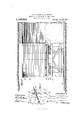
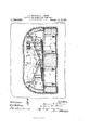
In the drawings. Figure 1 isa side eleva-. tion of a side-wall'form in place in a. tunnel, which is indicated in section; Fig. 2 a transverse section of the tunnel showing two side forms in end elevation; Fig. 3 a detail view of a part of one of the side forms. Fig. 4: a side elevation of an arch form; Fig.5 an end elevation of the same in place in a tunnel; Fig. 6 a side elevation of a machine for placing material in the tunnel arch; Fig. 7 a plan of the same; Fig. 8 an end view of the same; Fig. 9 an end view of a modified arrangement employing two placing devices; Fig. 10 a side elevation of amachine for supplying andpjlacing con- Y crete; Fig. 11 a plan of the same; Figs. 12
to 15 views of av further embodiment of some features of our -invent1 on.f ;f
A plant embodylng our invention 1n all its detailscomprises a pair of traveling side-' wall forms, an arch-concreteplacing apparatus, and a combined concrete supplying and placing apparatus. The latter apparatus has a double function, in that at times I it supplies concrete to the arch-concrete placlng apparatus and again it may be used to place concrete in the side walls of the tunnel, as will be clear, from the description hereinafter.
The traveling side wall forms.The side Patented 0011.12, 1915. I
wall forms, Figs. 1 and 2, are practically.
alike in construction with the exception that one is a right and thejot-her a left. A description of one will sufiice for a. full understanding of both, and hence the specific description of the right hand side form shown in Fig. 2, will be given. This side form comprises a truss-frame A, having grooved rollers an arranged to run upon a rail a laid along the footing a of the tunnel wall, asshown in Fig. 2.- Upon the inner side of. the truss-frame, that is to say, the side toward the center of the tunnel, are arranged a;
series of vertical struts B, Fig. 1, each consisting preferably of a pair of channel iron beams suitably secured to the truss-frame with their backs slightly separated. To the outside of the truss-frame is secured the wall-form proper which may be of any desired construction, but preferably consists of a plurality ofmetal plates a secured to vertical timbers c. The-wall form is given a shape corresponding to that of the inner face of the tunnel side-wall, and it is particularly advantageous to have this sidewall form archinward slightly at thejtop in order to form the lower portion of the 1 concrete arch lining, thereby giving a better clearance for the arch form, proper, or centering, as will be more fully explained in the description of the traveling arch form. In order to hold the wall-form in place, and at the same time to avoid blocking the tunnel, suitable means for this purpose is provided, said means comprising in tunnels through rock, bolts secured in the rock, as indicated at D Dand arranged to hold the upper and lower portions of the wall forms.
The bolts at the upper portion ofthe wallforms are provided with eyes into which are hooked suitable-hoobbolts D Whose loo inner ends are threaded and provided with washers, each hook-bolt passing through the upper end of its respective vertical strut in the space between the channel bars forming said strut; portion of the form pass the lower part of the wall-form proper, the
The bolts D at the lower through holes in engagement with they are formis now readyfor placing of concrete,
-bolts are loosened, thus letting endsof said bolts beingthreaded and pr0- For the purpose of allowing the ready transportation of the side-wall forms from one location to the next, a plurality of swinging bracesfE, are-hinged tov the yer-- tical struts, these swinging braces being pro Vided at their lower ends with rollers, c, which are arranged to run upon a rail 6, laid on the tunnel floor. In order to move the swinging braces inward to bring the rollers'into contactwith the corresponding rail ej or outward-s0 as to be flat against the side wall form, and to hold the braces in any position to which they may be adjusted,
suitable means is em loyed, for example.
jack-screws 6 Fig connected to the braces and to the. truss-frame A. In using this side-wall form the lower bolts D are put in place when the footing of the sidewall is laid, which is done prior to the use of the side-wall forms. The upper eye-bolts D are'set in holes drilled into the solid rock, being held by expansion belts in a well known manner. The side-wall form is run along its tracks a. e" to the desiredlocation, the swinging braces E being swung inward so that their rollers will move upon the rail e. T he hook bolts D are brought into the eye-bolts D, the bolts D are connected at the bottom andthe form thereby drawn into place The swinging braces may then be swung back flat against the inner face of the form, if desired, where held by the-jaclescrews 6 The which can be done in any suitable way, but preferably by means of the concrete-supplying and placing apparatus hereinafter described. So soon as the concrete is set, the swinging braces E are moved inward at the bottom by means of the jack-screws, and the' the weight ofthe form rest upon the two rails, of, e. ThQlIQOk bolts are then unhooked from the eyebolts and pushed along to its next location where it is again fixed in place in the manner hereinbefore described.
The traveling arch fomm-T his comprises two side trusses, F, Figs. 4c and 5, mounted on rollers f arranged to run upon the rails a located at the bottom of the tunnel upon -.the footings of the side walls. Upon these side trusses F is mounted an arch form or centering, consisting of archedstructural iron steel. ribs G, each having its ends connected. by a tie-rod 9 provided. with a suitable adjusting means such as a. turnbnohle g. Eaclrrib G is trussedby a plurality of horizontal'and verticalbraces g as indicated in Fig. 5 so as to leave ple'nt'y'of clearance through the center of the archform, this form of bracing or trussing of the top sill wedge blocks loosened the side-wall "form can be- I are provided workmen. The ribs Gr are covered with lagging H, and are supported uponlongitudinalgirders 1 Between these girders and of the side trusses F are pro- Vided means for bodily raising and lowering the arch form, this means comprising jacks.
indicated at For the purpose of holding the arch form steadily and to assist in bringingthe arch form into its correct operative position, wedge blocks 1' x5 and bearing blocks i are provided between the top sills, of the side trusses F and the longitudinal girders 1, these wedge-blocks being held against lateral displacement by tongue and groove connections with each other and wth the respective bearing blocks 2' above and below them. as will be clez r from Fig. 5. In order to holdthe wedge-blocks of a pair in the proper relation to each other when the arch form is adjusted by the jacks 2 to its proper height, the lower blocl: 52" of each set has a hook? which engages a pin 2- in its companion block. lVhe'n the arch the arch form is known to be atits correct height, assuming of course that the rails a. are at. the proper grade. Since these rails rest upon the concrete footings of the side walls, as indicated in Figs. 2 and 5, and as these footings are usually surfaced carefully on top, the rails a. arela'id to the proper grade without difficulty. When the concrete placed upon the arch form has set and it is desired to vadvance 'LllQTEOZ'IH, the hooks i may be released from their pins '5 the 'andthe jacks lowcred, thus lowering the arch form and freeing it from the concrete lining. Thereupon the whole arch form is moved. forward to the next location where it is again raised to place by the aclrs, the wedge blocks driven up and the hooks. latched over the pins. As the concrete which is put in'pl'ace by the aid of the side wall forms includes the lower part the concrete arch, there is no difiiculty in clearing the arch form" from the set concrete abo e it when lowering. the form. The turnbucltlcs g in the tierods g u as a matter oi precaution to djustnients in the width of permit sli gl the arch form. to be made readily, and to enable thearch "form. to be drawn in slightly at the bottom, which its elasticity will pen ,mit, in order to free it from the concrete in case it should stick.
From Fig. 5 it will be seen that the cen-- tral portion of the trussing is so arranged that by removing" two bolts, the central dependent brace and the two horizontal braces connected with thebottom of the dependent brace maybe swung to one side, as
shown Figs. 6, 7 and 8, is similar to thatdescribed by the dotted lines thus leaving a clearhead room for a purpose hereinafter explained.
I I Furthermore, the turn buckle 9' may be unscrew-ed so that the twohalves of the tension rod 9 may be swung to one side, for
example, in an upward direction, as indi cated in dotted lines in said Fig. 5, in which position the said halves of the tension rod may be' secured in-any suitable way as by tying. This provision of a truss arranged to be removed out of the center of the arch form','a-llo ws .the concrete placing machine,
when lowered to its lowest position, to pass that "instead of waiting thirty-six hours for the'concrete to set above one arch form,- the arch'concrete placingmachine can be run ahead, another-arch form can be run over it into place and the placing of the concrete over said second arch form can be proceeded with, and so,-also, with a third, or a fourth arch .form, if desired. Then when thelast 26' *itsconcrete to set, all the arch forms can be struck and run ahead, this greatly reducing the time'necessary for the work.
1 The arch concrete placing -appamtus.-
form has stood thirty-six hours in place for This apparatus indicated generally at. K,
in ourPatent No. 829903, differingpri'ncipall-yjin'the fact that it need not bemade to swing in an arc of acircle, but merely traverses the tunnel on-a pair of transverse rails, is, laid upona suitable substructnre, L, which may be of any desired construction to hold the machine at the required height 'for its work. Preferably this substructure is the same as that descr bed in our said patent, being open underneath to form a passageway for the tunnel traffic,
and mounted on rollers or wheels, Z, which run upon the rails e on which the. side-wall forms'run. This arch concrete placing machine can be raised and lowere'd bodily while maintaining the horizontal discharge portion of its conveyer in asubstantially hori-.
zontal plane, suitable jack-screws is, being provided for this purpose, these screws being driven by worm-wheels engaged by worms ifon transverse shafts A? which shafts are connected for simultaneous mov ment. as for example. by a sprocket-chain k One of the transverse shaftsis driven by a suitable motorfor example, an electric motor indicated at M. For the purpose of conveniently moving the machine trans- "ersely, a motor M is provided which has a gear-wheel m engaging a corresponding gear m on a longitudinal axle m ]ournaled in bearings m on the underside of the machine frame and having rollers or wheels mt fixed to it. The machine has a hopper, k which receives the concrete, and conveytunnel independently of the other part.
ing means, as for example, a-belt which carries the concrete up the inclined portionof the conveyer and then along the l1ori= zontal portion to the place of discharge over the arch-form. The construction of the frame, the belts and the means for drivin the same may be as disclosed in our sai patent, and hence need not be specifically described herein. 1
For the purpose of. guiding the machine in its vertical movement when raised or low ered by the jack screws 7;, suitable guide posts, as indicated at 70 may be secured to the machine base as shown in Fig. 6. The method of operating this device is as follows: The arch-form being in place, the machine is moved toward the arch form until the horizontal portion of its conveyer extends into the. space between the archform-and the tunnel roof, as shown in Fig. 6. Owing to the fact'that the machine can be raised or lowered, and can travel latermum-amount of handling. In wide tunnels 'and where great rapidity of 'COIIStIUCtIOII'IS desirable, two such arch-concrete placing machines may be employed, these two being fed from a common supplying apparatus, as for example, the concrete supplying and placing apparatus hereinafter, described. In Fig. 9 is shown a substructure provided with two suchar'ch-concrete placing devices, these being intended to work each at its own; side of the arch in aj direction toward each other, until the machines meet, whereupon one machine is withdrawn, and the other used to complete the central portion of the arch. lVith this. construction the substructure is made in two parts, each part being capable of movement, longitudinally of te nthis case, of course, the tunnel is assumed to be wide enough to allowv traffic tracks through each substructure, since if it'were tunnel. In the embodiment shown, in Figs.
10 and 11, taken. with Figs. 6 and 7, the said apparatus is mounted in a substructure similar to that employed with the arch-concrete placing apparatus and arranged to bedetachably coupled to the latter when desired, as. for example, by means of bolts n Fig. 6,
v which pass through a transverse girder Z on the front of the substructure L of the archconcrete placing device and through a similar girder n on the rear end of the substructure. N. The trout end of the substructure .for the combined concrete supplying apparatus is arranged to overhang somewhat as shown in Fig. 10, and on the upper side 01 this overhanging part is mounted a frame-work N carrying a rearward projecting overhead track N which has an overhanging part which may be suitably braced as shown in Fig. 10 by braces 17. On this overhead track moves a carriage N to which ,the hoisting device is attached, this being shown conventionally in the drawing as an larly adjustable, that and rope an. arranged to ordinary pulley n In practice the hoisting hoist a bucket n".
device is similar to that shown in our Patent 629903. The conveying apparatus conslsts of a belt conveyer P, arranged to swing vertically and mounted on a turn-table platform P, provided with rollers running on curved rails p 7;, Fig. .11 carried by the substructure X. The conveyor is guided in its vertical movements by posts, secured to the turntable platform. The conveyer belt is driven by a motor R, in the usual way. Above the lower end of the conveyer and over the center of the turntable, is mounted a} hopper S, above which terminates the overhanging portion of the overhead track of the elevating apparatus so that the bucket a may be discharged into the hopper. For the purpose of moving the substructure longitudinally on the tunnel-tracks, a motor, S, is provided, this being mounted on the substructure as shown and arranged to drive a transverse shaft 3 which is provided at each end with sprocket wheels .9 which are connected by sprocket chains 8 wheels 8 fixed to the track wheels a of the substiaicture, as will be clear from the drawings Initheernbodiment shown, the motor for propelling theysubstructure is a compressed air motor, and this is coupled to the transverse shafts by aworm gear indicated at 8 1 v The apparatus just described has two functions, viz. to place concrete in the side walls of the tunnel andv to supply concrete to the arch-concrete placing apparatus, Owing to the fact that the conveyer is angus to say, in an arc in a horizontal direction and also can be adjusted at different angles in a vertical ranged overt-he tunnel plane it can follow the hopper of the archconcrete placing apparatus and thus permits the latter apparatus to be moved freely fronr one position to another transversely,
maintaining a supply from the elevating or hoisting apparatus which of necessity is artracks. The hopper S of this combinedfidevice ismade large enough to act as a storage receptacle for a short interval, thusmaintaining the plant in fed from an intermittentsourfce oi supply placto sprocket can be swung inon' means for supplying crete-placing devices, this while ing concrete for the side-walls, the corn eyer swung to,the desired side and discharges the concrete back of the side wall forms. During this work this apparatus is not bolted or otherwise connected to the sub structure of the arch-concrete placing apparatus, and being means of propulsion can be readily and quickly moved along its track to discharge at any desired point behind the said side wall forms. Moreover, it can be swung from. one side to the other by hand so that it can work on either side wall.
In the use of a plant embodying our invention, the concrete footings for the side walls are first put in place in. any desired Qway, preferably, however, by shoveling the and set in operation to build the side walls.
Then the side wall forms are moved farther into the tunnel. to their next location and the side walls completed at such new location. Next, the arch-concrete placing apparatus is run into the tunnel and behind it the arch-form. The combined concrete placing and supplyingapparatuscan now feed the arch concrete placing apparatus, which places the concrete of the arch, while sections or" the side walls which are within the sidewall forms are setting. As soon as ]the arch-concrete'has been'plac'ed, and while the same is setting, the side-wall forms can be moved. ahead to the next section and the combined placing and supplying apparatus brought into operation to build the new section of side walls, during which time the concrete .arch is setting. At the end ot'this time the arch form is lowered and moved ahead to the next section, then raised into place and the work of building the new sec tion of the arch may be proceeded with. it will be seen that by the use of this plant, the. work can be carried on rapidly While at the same time the concrete is. given suflicient "time to set before the forms are moved. 4
In Figs. 12 to 15 is illustrated another structure embodying'some of the features of the invention. Referring to these figures, it will be observed that the embodiment of our invention, therein illustrated comprises two concrete placing devices indicated generally by the Roman numerals l. and H, and comboth of said conbeing indicated generally Each concreteplacing de vice comprises a conveyer T extending in the direction of. the length of the tunnel and having a horizontal section andan-inclined section, and a, conveyer T" extending transversely tothe axis of-the tunnel, this conveyer discharging into a hopper T at the Gm ken-m.
furnished with its own lower end of the inclined section of the 1ongitudinal conveyer and having a hopper .T of its own through which it is fed. The concrete placing device is provided with a suitable frame-work by means of'which the parts are held in proper relation to each other, the frame-work being mounted on a su1 )er-carriage 21 which can move on wheels 21 in the direction of the length of the tunnel upon rails 22, tied. together by members 23 and constituting a traversing carriage which can move transversely of the tunnel upon transverse tracks 24: carried upon a suitable substructure '25. In the preferred embodiment of our invention, this substructure consists of two parts, indicated generally at V and V each of which 1s similar to the substructure described in our said patent in that it is arranged so as to provide a passage way for the traffic over the tunnel track which it bridges. In the example illustrated, the substructure may be considered as comprising two traveling platforms, or frame-work each' mounted upon tracks in, its respective tunnel-tube so that it may be moved in the direction of the length of the tunnel. The traveling platforms also carry transverse rails 26, 27, 28,
travel the concrete-placing devices, and the v said overhead track device is located between the two concrete placing devices, being hi h enough to bridge all the mechanism of thfiatter except the concrete-placing con- Veyers. All the tracks carried by the two platforms are in two sections, one sect on be ing carried by each platform, so that the said platforms may be moved. independently of each other and when brought side by side in alinement, the overhead track device, the hoist mechanism, and the concrete-placing devices may be moved as desired along the respective tracks. The intermediate portions of the said tracks overhang the respective portions of the substructure and may be supported by temporary blocking or posts, or generally .by the center wall of a twin tube tunnel, when usetoin such a place.
The operation of this de ce is as follows:
- The concrete brought into the tunnel over the usual tunnel tracks is lifted in buckets from the cars on said tracks by the hoist mechanism. 1 As thisfcan travel transversely of the tunnel it can lift the buckets from either tunnel tube and can travel laterally of the tunnel until its overhead track or runway is in line with the track of the overhead track device. Then the bucket, which is supported by a traveler in the-usualway can be moved longitudinally of the tunnel along the overhead. track, which is adjustable laterally so that it may deliver the bucket overeither hopper of the respective concrete-placing devices, whereupon the bucket is discharged and returned to the hoist mechanism, which then is actuated to' lower the bucket to the car on the respective tunnel track.' The transversely arrangedconveyers of the concrete-placing devices deliver the concrete to the hoppers of the longitudinally arranged conveyers, from whence it is removed by said latter conveyers and discharged at the desired points. The concrete placing devices have means for vertically adjusting the longitudinally arranged conveyers, as for example, the jacks indicated at X. Furthermore, the transversely arranged conveye'rs are arranged to swing in a vertical plane and have a limited amount of movement together with their hoppers, in a direction transverse to the tun-= nel. so that as the longitudinally arranged conveyers are adjusted vertically, the discharge ends of. the respective transverse conveyers may be kept over the hoppers of Q a said longltudlnally arranged-conveyers.
Having thus fully described our invention, what we claim, is
1. In a machine for tunnel work, the combination, withan arch form and a side-wall form, of an arch-concrete placing devicearranged to place material over the arch-form,
and an angularly movable conveyer ar ranged to supply material to the arch-concrete placing device and to the side-wall form.
2. .In a machine for tunnel work, the combination, with an arch 'form, and a sidewall form, of an arch-concrete placing device arranged to place material over the arch form", 'a nd a concrete supplying mechanism arrangtd to supply material interchangeably to itiie arch-concrete placing device and to the s d'c-wall form.
3.- In machine for tunnel work, the combination, with an arch form, and a pair of side-wall forms, of anarch-concrete placing apparatus mounted between the side-wall forms and arranged to (place material over the arch-form, and an angularly movable concrete supplying mechanism arranged to supply material. lnterchangeably to either side-wall form and also to the arch-concrete placing device.
4. In apparatus for constructingtunnels, the combinationiot an arch form, side-wall forms arranged advance of the arch form,
ill
, veyer, and means forthe first tracks, and
a concrete-placing mechanism arranged to place material over the arch form, a con= imparting an angular movementto the conveyer whereby itmay supply material to the concrete placing 'mechanism or behind the side forms.
5. In apparatus for constructing tunnels, the'combina-tion of parallel tracks, an arch form arranged't'o travel on the outer tracks, a concrete-placing mechanism arranged to travel on the inner track, and to supply ma- ':.terial over the arch form, and side forms "arranged to travel on one rail each of. both tracks. p 6. In a machine for tunnel work, the combination, with an arclfsform, frames upon which said arch form is supported, and
tracks upon which said frames move, of a concrete placing device arranged to place concreter over the arch form, a substructure upon which said device is supported and.
tracks upon which said substructure runs, said tracks being substantially parallel to a side form arranged to run upon one rail each of both tracks.
i 7 In amachine for tunnel work, the com-i bination,
with an arch form, frames upon which said arch form is supported, and
tracks upon whic said frames'move, of a concrete placing device arranged tcfplace concrete over the arch form, a suhstrrcture upon-which said device is supported and tracks upon which said substructure runs, said tracks being substantially parallel to the first tracks, a side form arranged to run upon one rail each of bothtracks, and a conveying mechanism arranged to del1ver, concrete to the arch-concreteplacing device'and to the side form.
8. In anarch form, arched ribs and adjustably tensionable tierod connecting the ends of said ribs, of a truss bracing composed of a plurality of horizontal and vertical members, the vertical members having, their upper ends secured to the said ribs, the lowest horizontal members having their opposite ends secured to the ribs and to the lower ends of the low est vertical members, and the intermediate horizontal 'members having their opposite ends secured to the lower end of one vertical member and to an intermediate point of the frame and braces arranged to run upon par' allel tracks. 7 i f 10. The combination, with a pair of sidewall forms having curved upper ends, to form the lower portion of the arch, and a carriage for supporting and transporting said form, of an arch form arranged to,
form the remainder of the arch, and means combination of combination, the combination, with at any desired arsenal independent of the side-wall form and its carriage for supporting and transporting said arch form.
1 1. In apparatus for building tunnels, the combination of a traveling concrete-placing mechanism, and a series of traveling forms arranged to move telescopically'past the said placing niechanisf rand be successively secured in position to receive materialtherefrom.
12. In apparatus for building tunnels, the a traveling concrete-placing mechanism, and a series of traveling are 1 forms, each having truss bracing so arranged as to provide clear head room whereby the said forms may be moved telescopically past the placing mechanism and be successively brought into position to receive material therefrom. i
13. In apparatus for building tunnels, the,
combination of a concrete-placing mechanism, whereby it may extend either over or below an arch. form, and a traveling arch form ar ranged to move telescopically past said placing mechanism and be secured in position to receive material therefrom.
14. In a machine for tunnel Work, the combination, with an arch form. and a side wall form arranged in advance of the arch form, of a vertically and laterally movable concrete placing device arranged to place material over the arch form, and a concrete supplying mechanism arranged to supply material interchangeably to the side wal form and to th'e arch concrete placing device in any adjusted position of the latter.
15. In a machine for tunnel work, the with an arch-form," frames upon which said arch-form is supported, and a concrete-placing device arranged to place concrete over the arch-form, said concreteplacing device being arranged to receive materials at a point below the top of the arch-form, of a substructure on which said concrete-placing device is mounted,
upon which said substructure runs, said 1 tracks being substantially parallel. to the first more; a side-wall form'arranged to run upon one rail each of both -tra'cks, and conveying means mounted upon the sub structure and arranged to move into means for adjusting said mechanism
Priority Applications (1)
| Application Number | Priority Date | Filing Date | Title |
|---|---|---|---|
| US38392907A US1156830A (en) | 1907-07-15 | 1907-07-15 | Method of and apparatus for tunnel-work. |
Applications Claiming Priority (1)
| Application Number | Priority Date | Filing Date | Title |
|---|---|---|---|
| US38392907A US1156830A (en) | 1907-07-15 | 1907-07-15 | Method of and apparatus for tunnel-work. |
Publications (1)
| Publication Number | Publication Date |
|---|---|
| US1156830A true US1156830A (en) | 1915-10-12 |
Family
ID=3224886
Family Applications (1)
| Application Number | Title | Priority Date | Filing Date |
|---|---|---|---|
| US38392907A Expired - Lifetime US1156830A (en) | 1907-07-15 | 1907-07-15 | Method of and apparatus for tunnel-work. |
Country Status (1)
| Country | Link |
|---|---|
| US (1) | US1156830A (en) |
Cited By (2)
| Publication number | Priority date | Publication date | Assignee | Title |
|---|---|---|---|---|
| US2590683A (en) * | 1949-02-21 | 1952-03-25 | Ralph E Clapp | Tunnel lining form |
| US4146382A (en) * | 1975-10-21 | 1979-03-27 | Hannes Willisch | Method of and apparatus for the treatment and purification of refuse, or refuse/sewage sludge mixtures by means of composting |
-
1907
- 1907-07-15 US US38392907A patent/US1156830A/en not_active Expired - Lifetime
Cited By (2)
| Publication number | Priority date | Publication date | Assignee | Title |
|---|---|---|---|---|
| US2590683A (en) * | 1949-02-21 | 1952-03-25 | Ralph E Clapp | Tunnel lining form |
| US4146382A (en) * | 1975-10-21 | 1979-03-27 | Hannes Willisch | Method of and apparatus for the treatment and purification of refuse, or refuse/sewage sludge mixtures by means of composting |
Similar Documents
| Publication | Publication Date | Title |
|---|---|---|
| US3523343A (en) | System for the production of cast concrete members | |
| US3744945A (en) | Apparatus for modular concrete constructions | |
| US3985480A (en) | Apparatus for the sectional cantilever construction of bridge girder systems | |
| US1751147A (en) | Method of lining tunnels with concrete and apparatus therefor | |
| US3845930A (en) | Telescopic supports for adjustable roof and beam form | |
| JPS5812169B2 (en) | Baradzumi Seisanbutsu no Stotsukunotoriatsukaisouchi | |
| US3151732A (en) | Method of and apparatus for transporting concrete | |
| US1156830A (en) | Method of and apparatus for tunnel-work. | |
| US3003219A (en) | Method and means for erecting elongated structures of concrete | |
| US2827771A (en) | Canal lining machine | |
| US3590590A (en) | Tunnel building | |
| US1716125A (en) | Method of lining tunnels with concrete and apparatus therefor | |
| US3659979A (en) | Plant for manufacturing small structural elements | |
| USRE26298E (en) | Method of and apparatus for transporting concrete | |
| DE2453281C3 (en) | Movable formwork scaffolding | |
| US1524325A (en) | Form | |
| US2258918A (en) | Self-propelled tilting hoist | |
| JP2779185B2 (en) | Underwater casting equipment for dry mix materials | |
| US829903A (en) | Machine for handling material for tunnel-arch construction. | |
| US1293006A (en) | Method and apparatus for constructing arches. | |
| US387476A (en) | Excavating apparatus | |
| US301927A (en) | Device for constructing tunnels | |
| US796498A (en) | Art of mining coal. | |
| US1380400A (en) | Method of and apparatus for tunnel-work | |
| US1002524A (en) | Apparatus for tunnel construction. |