US164137A - Improvement in compound iron columns for bridges - Google Patents
Improvement in compound iron columns for bridges Download PDFInfo
- Publication number
- US164137A US164137A US164137DA US164137A US 164137 A US164137 A US 164137A US 164137D A US164137D A US 164137DA US 164137 A US164137 A US 164137A
- Authority
- US
- United States
- Prior art keywords
- rails
- bridges
- column
- improvement
- space
- Prior art date
- Legal status (The legal status is an assumption and is not a legal conclusion. Google has not performed a legal analysis and makes no representation as to the accuracy of the status listed.)
- Expired - Lifetime
Links
- 150000001875 compounds Chemical class 0.000 title description 4
- XEEYBQQBJWHFJM-UHFFFAOYSA-N iron Chemical compound [Fe] XEEYBQQBJWHFJM-UHFFFAOYSA-N 0.000 title 4
- 229910052742 iron Inorganic materials 0.000 title 2
- 238000010276 construction Methods 0.000 description 6
- 241001474728 Satyrodes eurydice Species 0.000 description 4
- 238000005266 casting Methods 0.000 description 4
- 238000010422 painting Methods 0.000 description 4
- 230000000875 corresponding Effects 0.000 description 2
- 239000011796 hollow space material Substances 0.000 description 2
- 239000002184 metal Substances 0.000 description 2
- 229910052751 metal Inorganic materials 0.000 description 2
- 230000003647 oxidation Effects 0.000 description 2
- 238000007254 oxidation reaction Methods 0.000 description 2
Images

Classifications
-
- E—FIXED CONSTRUCTIONS
- E04—BUILDING
- E04H—BUILDINGS OR LIKE STRUCTURES FOR PARTICULAR PURPOSES; SWIMMING OR SPLASH BATHS OR POOLS; MASTS; FENCING; TENTS OR CANOPIES, IN GENERAL
- E04H12/00—Towers; Masts or poles; Chimney stacks; Water-towers; Methods of erecting such structures
- E04H12/02—Structures made of specified materials
- E04H12/08—Structures made of specified materials of metal
Definitions
- My invention relates to improvements in the compression-members of a truss, such as length of the column between them, the same united snugly with metallic braces or straps.
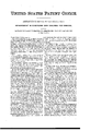
- Fig. 2 shows three railway T-rails with their flanges adjacent to each other, inclosing a hollow space down through the center of the column, and it also represents a metallic staybrace on the interior of the column in the open space.
- Fig. 3 represents four rails with their flanges placed adjacent to each other, inclosin g a square space down through the center of the column.
- Fig. 4 represents a similar view, except that the heads of the rails are placed adjacent to each other, instead of the flanges.
- the object of this invention is to form from the said railway T-rails hollow columns-that is, columns that have a central open space, the metal being thrown into the surface or shell surrounding this open space, whereby there is combined great strength with lightness.
- Fig. 1 three rails are shown with their heads turned toward each other.
- A are the rails.
- B are suitable metallic straps, whereby the said rails are firmly united at different lengths in the column, but leaving a space, 0, extending centrally the whole length of the column.
- D in Fig. 2 is a metallic stay-brace of any kind, as, for instance, a casting. It is placed within the space 0, and serves to hold the rails A in their relative positions. Bolts d and straps B, with the nuts 01, serve to firmly unite the rails together and to the piece D. It is evident that the piece D may be dispensed with, and, instead thereof, the rails may be united in a manner similar to the device shown in Fig. 1.
- Fig. 3 is represented a rectangular cen tral space, 0, bounded by four railway T-rails, with their flanges adjacent to each other. They are united by suitable straps B, and may or may not be provided with suitable stays, like the stay D in Fig. 2.
- Fig. 4 is presented a similar arrangement to that shown in Fig. 3, except that the heads are adjacent to each other instead of the flanges.
- Fig. 4 presents a more open form than Fig. 3, and is more readily accessible for the purpose of painting on the interior of the space 0 than the device. shown in Fig. 3.
- the devices shown in Figs. 1 andet may likewise sion-members required in bridge or roof trusses, and in any other kind of structure, may be formed.
- brace suit-able for the three-rail column, showing the lugs e, is represented at the bottom in Fig. 2.
- stay-brace D is represented as an open-frame casting.
- Bolts (1 pass through diagonally, and clamp the plates B firmly upon the angles of the column, thus binding the rails firmly together.
- Lugs e and recesses e are here employed in a manner similar to that above described.
- the bolts cl do not pass through the column exactly at right angles to the axis of the column, but are inclined thereto just sufiiciently far to permit the bolts to pass each other at the center; or, instead of inclining them, one bolt may bedropped down into a different plane from that containing the other bolt, so as to permit them to pass.
- Fig. 4 presents the column formed of four rails with their heads toward each other. They are strapped together by straps B uniting the rails, two and two. Straps B then unite each rail with the rail next to it. It will be seen that the rails are prevented not only from falling apart, but the straps B serve to maintain them' in their relative positions.
- a compression-member of a bridge-truss or otherstructure consisting of a hollow column formed by arranging railway T-rails about a central open space and fastening them rigidly together, substantially as and for the purpose described.
Description
A. E. BROWN.
Compound lrp n coiumns for Bridges.. NO. I64. I37, Patentedlune8,1875.
III-[Il Ili'll I IITTI WWEESEE WNW? THE GRAPHIC CO.PHOTO-LITH.39&41PARK PLACLNN.
UNITED STATES PATENT OFFICE.
ALEXANDER E. BROWN, OF CLEVELAND, OHIO.
IMPROVEMENT IN COMPOUND IRON COLUMNS FOR BRIDGES.
Specification forming part of Letters Patent No. 1 64,137, dated J une 8, 1875; application filed February 15, 1875.
To all whom it may concern:
Be it known that I, ALEXANDER E.BROWN, of Cleveland, county of Ouyahoga, State of Ohio, have invented a new Improvement in Bridges; and declare the following to be a full, clear, and exact description thereof, such as will enable others skilled in the art to which my invention relates to make and use it,
reference being bad to the accompanying drawings, which form a part of this specification.
My invention relates to improvements in the compression-members of a truss, such as length of the column between them, the same united snugly with metallic braces or straps.
' Fig. 2 shows three railway T-rails with their flanges adjacent to each other, inclosing a hollow space down through the center of the column, and it also represents a metallic staybrace on the interior of the column in the open space. Fig. 3 represents four rails with their flanges placed adjacent to each other, inclosin g a square space down through the center of the column. Fig. 4 represents a similar view, except that the heads of the rails are placed adjacent to each other, instead of the flanges.
In the construction of the compression-members of bridge-trusses and other trusses, as well as compression-members of other structures, great expense is incurred, because each different form of cross-section which may be required necessitates special machinery for its construction. I have discovered that railway T-rails of ordinary construction, and which may or may not have become worn out, so as not to'jbe effectual in. a railway-track, may be combined with each other in such a manner as to form the various styles of compressionmembers required in different structures.
This application forms one of a number of applications for Letters Patent that I have made for the purpose of securing various useful combinations of railway T-rails for this purpose.
The object of this invention is to form from the said railway T-rails hollow columns-that is, columns that have a central open space, the metal being thrown into the surface or shell surrounding this open space, whereby there is combined great strength with lightness.
In Fig. 1 three rails are shown with their heads turned toward each other. A are the rails. B are suitable metallic straps, whereby the said rails are firmly united at different lengths in the column, but leaving a space, 0, extending centrally the whole length of the column.
In Fig. 2 the rolls are similarly arranged, except that the flanges, instead of the heads, are placed close together, so that they inclose a triangular space, 0, between them.
It is evident from the drawings that the device shown in Fig. l is more open than that shown in Fig. 2, and the interior space 0 is more readily accessible for the purpose of painting to prevent oxidation. D in Fig. 2 is a metallic stay-brace of any kind, as, for instance, a casting. It is placed within the space 0, and serves to hold the rails A in their relative positions. Bolts d and straps B, with the nuts 01, serve to firmly unite the rails together and to the piece D. It is evident that the piece D may be dispensed with, and, instead thereof, the rails may be united in a manner similar to the device shown in Fig. 1.
In Fig. 3 is represented a rectangular cen tral space, 0, bounded by four railway T-rails, with their flanges adjacent to each other. They are united by suitable straps B, and may or may not be provided with suitable stays, like the stay D in Fig. 2.
In Fig. 4 is presented a similar arrangement to that shown in Fig. 3, except that the heads are adjacent to each other instead of the flanges. Fig. 4 presents a more open form than Fig. 3, and is more readily accessible for the purpose of painting on the interior of the space 0 than the device. shown in Fig. 3. The devices shown in Figs. 1 andet may likewise sion-members required in bridge or roof trusses, and in any other kind of structure, may be formed.
On the stay-brace D I prefer to form lugs e,
which, by fitting into corresponding recesses or notches e in the rail, serve, with the straps B and the nuts 01, to hold the Whole structure snugly together.-
The triangular form of brace suit-able for the three-rail column, showing the lugs e, is represented at the bottom in Fig. 2.
When the four rails are employed, as in Fig. 3, the inner form of stay-brace D is represented as an open-frame casting. Bolts (1 pass through diagonally, and clamp the plates B firmly upon the angles of the column, thus binding the rails firmly together.
Lugs e and recesses e are here employed in a manner similar to that above described. The bolts cl do not pass through the column exactly at right angles to the axis of the column, but are inclined thereto just sufiiciently far to permit the bolts to pass each other at the center; or, instead of inclining them, one bolt may bedropped down into a different plane from that containing the other bolt, so as to permit them to pass.
The sectional figure shown in Fig. 4: presents the column formed of four rails with their heads toward each other. They are strapped together by straps B uniting the rails, two and two. Straps B then unite each rail with the rail next to it. It will be seen that the rails are prevented not only from falling apart, but the straps B serve to maintain them' in their relative positions.
What I claim is- 1. A compression-member of a bridge-truss or otherstructure, consisting of a hollow column formed by arranging railway T-rails about a central open space and fastening them rigidly together, substantially as and for the purpose described.
2. The column or hollow compression-member, consisting of the combination, with three or more railway T-rails, A, of the central staybrace D and suitable fastenings, whereby the rails are bound snugly together, substantially as and for the purpose described.
In testimony whereof I have signed my name to this specification in .the presence of two subscribing witnesses.
ALEXANDER E. BROWN.
Publications (1)
| Publication Number | Publication Date |
|---|---|
| US164137A true US164137A (en) | 1875-06-08 |
Family
ID=2233546
Family Applications (1)
| Application Number | Title | Priority Date | Filing Date |
|---|---|---|---|
| US164137D Expired - Lifetime US164137A (en) | Improvement in compound iron columns for bridges |
Country Status (1)
| Country | Link |
|---|---|
| US (1) | US164137A (en) |
Cited By (3)
| Publication number | Priority date | Publication date | Assignee | Title |
|---|---|---|---|---|
| US2444091A (en) * | 1944-07-25 | 1948-06-29 | Carlsen Olaf | Structural section and structural members composed thereof |
| US20050271340A1 (en) * | 2004-04-08 | 2005-12-08 | Ori Weisberg | Photonic crystal waveguides and systems using such waveguides |
| US20060201206A1 (en) * | 2001-07-16 | 2006-09-14 | Gilles Benoit | Fiber waveguides and methods of making the same |
-
0
- US US164137D patent/US164137A/en not_active Expired - Lifetime
Cited By (3)
| Publication number | Priority date | Publication date | Assignee | Title |
|---|---|---|---|---|
| US2444091A (en) * | 1944-07-25 | 1948-06-29 | Carlsen Olaf | Structural section and structural members composed thereof |
| US20060201206A1 (en) * | 2001-07-16 | 2006-09-14 | Gilles Benoit | Fiber waveguides and methods of making the same |
| US20050271340A1 (en) * | 2004-04-08 | 2005-12-08 | Ori Weisberg | Photonic crystal waveguides and systems using such waveguides |
Similar Documents
| Publication | Publication Date | Title |
|---|---|---|
| US164137A (en) | Improvement in compound iron columns for bridges | |
| US444579A (en) | Lengthening metallic beams and girders | |
| US108663A (en) | Improvement in tubular bridges | |
| US337666A (en) | I i x i i | |
| US774205A (en) | System of upper framing for railway-cars. | |
| US742873A (en) | Storage-bin. | |
| US160574A (en) | Improvement in wrought-iron columns | |
| US514665A (en) | Edward w | |
| US1794287A (en) | Double-slip point for rails | |
| US605474A (en) | Bridge construction | |
| US118948A (en) | Improvement in wrought-iron columns | |
| US153170A (en) | Improvement in wrought-iron columns | |
| US1093326A (en) | Telegraph-pole and the like. | |
| US1172788A (en) | Rail fish-plates. | |
| US698605A (en) | Construction of structures sustaining cross strains. | |
| US159315A (en) | Improvement in bridges | |
| US1238276A (en) | Elevated-railroad structure. | |
| US127564A (en) | Improvement in truss-bridges | |
| US171377A (en) | Improvement in iron fences | |
| US703609A (en) | Car-bolster. | |
| US393433A (en) | Truss-bridge connection | |
| US526261A (en) | John ehoads | |
| US919273A (en) | Reinforcing-truss for concrete structures. | |
| US488283A (en) | meig-s | |
| US159305A (en) | Improvement in wrought-iron columns |