US1851439A - Handle shaft for golf clubs - Google Patents
Handle shaft for golf clubs Download PDFInfo
- Publication number
- US1851439A US1851439A US254140A US25414028A US1851439A US 1851439 A US1851439 A US 1851439A US 254140 A US254140 A US 254140A US 25414028 A US25414028 A US 25414028A US 1851439 A US1851439 A US 1851439A
- Authority
- US
- United States
- Prior art keywords
- shaft
- handle
- club
- handle shaft
- tubular
- Prior art date
- Legal status (The legal status is an assumption and is not a legal conclusion. Google has not performed a legal analysis and makes no representation as to the accuracy of the status listed.)
- Expired - Lifetime
Links
Images
Classifications
-
- A—HUMAN NECESSITIES
- A63—SPORTS; GAMES; AMUSEMENTS
- A63B—APPARATUS FOR PHYSICAL TRAINING, GYMNASTICS, SWIMMING, CLIMBING, OR FENCING; BALL GAMES; TRAINING EQUIPMENT
- A63B60/00—Details or accessories of golf clubs, bats, rackets or the like
-
- A—HUMAN NECESSITIES
- A63—SPORTS; GAMES; AMUSEMENTS
- A63B—APPARATUS FOR PHYSICAL TRAINING, GYMNASTICS, SWIMMING, CLIMBING, OR FENCING; BALL GAMES; TRAINING EQUIPMENT
- A63B60/00—Details or accessories of golf clubs, bats, rackets or the like
- A63B60/06—Handles
-
- A—HUMAN NECESSITIES
- A63—SPORTS; GAMES; AMUSEMENTS
- A63B—APPARATUS FOR PHYSICAL TRAINING, GYMNASTICS, SWIMMING, CLIMBING, OR FENCING; BALL GAMES; TRAINING EQUIPMENT
- A63B53/00—Golf clubs
-
- A—HUMAN NECESSITIES
- A63—SPORTS; GAMES; AMUSEMENTS
- A63B—APPARATUS FOR PHYSICAL TRAINING, GYMNASTICS, SWIMMING, CLIMBING, OR FENCING; BALL GAMES; TRAINING EQUIPMENT
- A63B60/00—Details or accessories of golf clubs, bats, rackets or the like
- A63B60/54—Details or accessories of golf clubs, bats, rackets or the like with means for damping vibrations
Definitions
- My invention relates to golf clubs, and more particularly to the modification of tubular'metallic shafts for such clubs to enable the simulation of the inherent characpg teristics of the traditional hickory shaft.
- Tubular metallic shafts ofboth'tapered and cylindrical stepped formation are quite extensively employed as substitutes for the cus tomary hickory shafts. While such tubular n?
- shafts possess the desirable characteristics of being non-breakable and beingsubstantial- 'ly unafiected by climatic, temperature and humidity changes, they are lacking in certain other characteristics of the usual hickory f shaft, which induces the harmonious action of the club as a whole and affords a characteristic feel which the skilled player has learned to expect and prefers to experience, and which to a very great degree determines the quality of his playing.
- One of the objections to the metallic shaft for golf clubs is its inability to respond to torsional strain. At the moment of impact the natural wooden shaft tends to twist or yield torsionally,thus absorbing'the shock and by the reaction from such torsional, movement gives to theball an impetus and action in flight, which cannot be obtained by the ordinary metal shaft.
- suehresult can be obtained longitudinally splitting.
- the handle grip per- 'tion of the tubular metallic shaft only in -itsverticalaxial plane. That is to,say,' the best resultis obtained in the pitching or ap"- bottom side as the clubrests with its 5019 1 011 .proach group of clubs by longitudinally split- .ting the shaft either on its exact topside or its thesground, or such shaft may belongitudinalk ly slit on both the top and bottom sides. thus leaving two substantially semi-cylindrical strips or tongues which are laterally disposed in the direction ofthe swingingmovement of the club.
- Such slitting of the tubular shaft only in its vertical "axial plane permits alimited degree of whip action or I bending momentin the direction of the stroke greater than in a" direction .at; right angles thereto and also permits alimited degree of torsionalyielding offthe shaft atthe moment ofimpact suflicient to relieve the shock and J absorb vibration without, however, interfer Pic I Views.
- afcoreiwhi'ch is preferably of wood, but which" might-be 'rubber,-'fiber er other material;
- The'coreis preferablyof a light','rather soft or resilient material", and if of wood, bass wood, light pine, or balsa wood is-ipreferred.
- The-object of the invention is to improve the construction of metallic shafts-for golf clubs, polo mallet's, croquet mallets, and the like whereby they will not onlypossess greatandbending strain and will relieye the shock and vibration, whereby'the wri'sts' will be, less fatigued.
- a further object o'fthe invention is to pro- Vide' ajmodified metallicshaft which will "afford'better control ofthe club and while suflici-e'ntly resistant'to secure accuracy will posse s's sufficient. yielding i tendency to. insure a lra'rmo'niousaction of the'clu'bas awhole,and
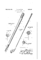
- Fig. 1 is .p'erspective'yiew of an assembled golf-club in whi'clrthefipre sentinvention'is embodied.
- Fig.2 is'an enlargeddetail View oi the upper portion of the "handle. 'sh'aftfofthe goltclub showing the l longitudinal. slit by which the present'e fli- ":c'i-ent action. achieved.
- I'Fig. 13 is a transyerse sectional view'on 'line 3i.3 of Fig. 2; 'Fig.
- 4' is a similar sectional yiew showing however, :a' single slitin the tubular shaft. 5 affnrther modification. f i Lilieparts areindicatedlbysimilar characters of "reference throughout tlie several So, in the present instance, "it has” acquires itsdesignation asan iron. Thebeen found that by spl tting the-handle shaft handle 'shaftjZ isnietallic and of tubular;
- 1 is the golf club head, 2 the shaft and 3 the hand grip portion.
- an iron of theapproach or pitching type has been shown.
- the present invention is applicable to the handle shaft of any type of golf club, but 'is,par-" I 'tieul-arly adapted to any'of those of the present approach or pitching; group. .Tlie' head l ef the cldhfis oif'metal', from wh ch" 1t form. That illustrated is uniformly tapered, although at the present time 7 popular type of metallic handle shaft is otsteppedr forcylindrical-form, but of differentf'diameter,
- the present invention is equallyfapplicable to either style of shaft; "Thelarger end of the tubular handle shaft 2, which vfornis thee handle-portion, is longitudinally slotted as at 4.
- Thes'haft, 2 isxpositioned inthe-The'a'd 1 in such relationthat the longitudinalfslit ()1.Sl1tS as the case may in the handle shaft are disposed in the vertical aXialplan-e. That 'is'to say the slit is positioned either I on the top or; on the bottom of the tubular I shaft whenthe "club rests with its sole upon the ground.
- the handle shaft is preferably slit-at diametrically.
- the split portion of the "shaft maybe suitably packed. with cotton waste,'o r filled with a'waXy composition, or
- the handle grip portion is wrapped'with tape, or the like, to maintain thesemi-circular. fingers 5 in position about the insert core 6, v "and theusua'l padding and leather grip cover 139 is applied, as shown at 3 in Fig. 1.
- the slit portion of the metal shaft does not extend beyond the covered grip portion 3.
- this is not essential and to meet the, requirements and peculiarities of golfers the slits a may be extended to various degrees beyond the limit of the wrapped handle grip portion 3.
- varying degrees of resiliency or yielding effect to torsional strain may be achieved.
- thelongitudinal slits may be spaced less than a half turn apart, and likewise different action and results may be had by varying the position of the longitudinal slit more or less 1 limited to the specific details shown, but that away from the vertical plane when the sole of the club rests upon the ground.
- not more than two such slits are ordinarily employed. Some players prefer more. torsional reaction or more whip than others and the different manner in which various players strike the ball may be compensated for by positioningthe longitudinal slits in difi'erentpircumferem ORGE w. ATTEi N; f a
Description
March 29, 1932. 5, w, MATTERN 1,851,439
HANDLE SHAFT FOR GOLF CLUBS Filed Feb. 13, 1928 gameqv aim attozweq Patented Mar. 29, 1932 I :UNITED STATES GEORGE'WMATTERN, or DAYTON, 0 10, essrenonmomnn cnAwronngmcenneonnnn i canny COMPANY, or DAYTON, 01 10, VZQALCORI'ORATION OFLOHIO' 7 i HANDLE sHAr r non eonnoruns Application filed Februar 13, 1928. Seria1. n at 1,140.
My invention relates to golf clubs, and more particularly to the modification of tubular'metallic shafts for such clubs to enable the simulation of the inherent characpg teristics of the traditional hickory shaft. Tubular metallic shafts ofboth'tapered and cylindrical stepped formation are quite extensively employed as substitutes for the cus tomary hickory shafts. While such tubular n? shafts possess the desirable characteristics of being non-breakable and beingsubstantial- 'ly unafiected by climatic, temperature and humidity changes, they are lacking in certain other characteristics of the usual hickory f shaft, which induces the harmonious action of the club as a whole and affords a characteristic feel which the skilled player has learned to expect and prefers to experience, and which to a very great degree determines the quality of his playing. One of the objections to the metallic shaft for golf clubs is its inability to respond to torsional strain. At the moment of impact the natural wooden shaft tends to twist or yield torsionally,thus absorbing'the shock and by the reaction from such torsional, movement gives to theball an impetus and action in flight, which cannot be obtained by the ordinary metal shaft. The result of this inability to respond tothis strain excessive yibration, frequently causing numbness, or .a'disagreeable stinging sensation. This excessive vibration andlack of responsivenessof a metallic shaft to torsional strains, which are ordinarily absorbed by'the traditional woodenshaft, causes undue fa t gue to the hands and wristsof the golfer. These objectionable features of the metallic shafts substantially offset the good charac-' .mashie, thespade mashie, mashie niblick,
and shock is to transmitto the players hands circumference shaft. It is found thatSuCh patented construction tanceclubs, orfthose employed for lon'ger sh t is quiteefficient andquitesatisfactory for i 1 certain kmds of clubs, particularly thewdis- Such .clubs in which maximum rei sponsivenessto torsional strain and also whip action isjdesirable are all ofthewooden head clubs, to W1't, the driver, spoon and brassie, and certain irons including the driving cleek,
However, for clubs of, the pitching or approach group employed forshorter shots, a-
shaft which is more stiff and firm than those of the distanceggroup ofrjclubs, but lacking the driving iron, mid-iron andmid-mashie.
to.take turfii. Inforder to afford better control and to aflordproper response and l ar-- monious action of the pitchingorapproach group of club s, includingthemashie ironQthe jigger, niblick {and putter, withouthowever transmitting to the hands of the golferthe objectionable vibratiomandshock, it; has :been
found. that suehresult can be obtained longitudinally splitting. the handle grip per- 'tion of the tubular metallic shaft only in -itsverticalaxial plane. That is to,say,' the best resultis obtained in the pitching or ap"- bottom side as the clubrests with its 5019 1 011 .proach group of clubs by longitudinally split- .ting the shaft either on its exact topside or its thesground, or such shaft may belongitudinalk ly slit on both the top and bottom sides. thus leaving two substantially semi-cylindrical strips or tongues which are laterally disposed in the direction ofthe swingingmovement of the club. Such slitting of the tubular shaft only in its vertical "axial plane permits alimited degree of whip action or I bending momentin the direction of the stroke greater than in a" direction .at; right angles thereto and also permits alimited degree of torsionalyielding offthe shaft atthe moment ofimpact suflicient to relieve the shock and J absorb vibration without, however, interfer Pic I Views.
adapted for use inclubs of the distance -g'roup is seemingly small, golf is an'art in which the small differences and distinctions, Whl-ClLSGGHi of minor importance in other arts,-become 1 the determining factors (if-successful or good golfing.
onlyin its verticalaxial plane'either on the top or. bottom or at diametrically opposite points, the same elficiency can be given to the approach-group of club's'fas was given to the driver group by-th'e'construction shown, in the prior patentreferred'tOQ Q Within the splitend ofthe tubular shaft there'is inserted afcoreiwhi'ch is preferably of wood, but which" might-be 'rubber,-'fiber er other material; The'coreis preferablyof a light','rather soft or resilient material", and if of wood, bass wood, light pine, or balsa wood is-ipreferred.
[The-object of the invention is to improve the construction of metallic shafts-for golf clubs, polo mallet's, croquet mallets, and the like whereby they will not onlypossess greatandbending strain and will relieye the shock and vibration, whereby'the wri'sts' will be, less fatigued. g
A further object o'fthe invention is to pro- Vide' ajmodified metallicshaft which will "afford'better control ofthe club and while suflici-e'ntly resistant'to secure accuracy will posse s's sufficient. yielding i tendency to. insure a lra'rmo'niousaction of the'clu'bas awhole,and
-"ffeeil' offthe customaryhickoryshaft. I Witli' the above primary and otherfincidental :obj ectsin View, as-will inoreli'ullj'r' ap- 'pearfin the "specification, ithe invention consists of the features of'construction, the parts and'eonrbina'tions 'thereofliand the mode of operatiomor their equivalents, ashereinafter "described andls'et forthin the claim. I
'.' Referringto the accompanying drawings, wherein is shown the preferred, but obviously notfnece'ssarilythe only form of embodiment of the invention, Fig. 1 is .p'erspective'yiew of an assembled golf-club in whi'clrthefipre sentinvention'is embodied. Fig.2 is'an enlargeddetail View oi the upper portion of the "handle. 'sh'aftfofthe goltclub showing the l longitudinal. slit by which the present'e fli- ":c'i-ent action. achieved. I'Fig. 13 is a transyerse sectional view'on 'line 3i.3 of Fig. 2; 'Fig. 4' is a similar sectional yiew showing however, :a' single slitin the tubular shaft. 5 affnrther modification. f i Lilieparts areindicatedlbysimilar characters of "reference throughout tlie several So, in the present instance, "it has" acquires itsdesignation asan iron. Thebeen found that by spl tting the-handle shaft handle 'shaftjZ isnietallic and of tubular;
'nia'tion" wherein successive port-ionsi'are of er efiiciency but will be responsive toftorsional golfers hands and which will simulate the ieharacteristics and In the accompanying. drawings, 1 is the golf club head, 2 the shaft and 3 the hand grip portion. For pui'pose'of illustration an iron of theapproach or pitching type has been shown. It is to be understood that the present invention is applicable to the handle shaft of any type of golf club, but 'is,par-" I 'tieul-arly adapted to any'of those of the present approach or pitching; group. .Tlie' head l ef the cldhfis oif'metal', from wh ch" 1t form. That illustrated is uniformly tapered, although at the present time 7 popular type of metallic handle shaft is otsteppedr forcylindrical-form, but of differentf'diameter,
' The" present invention is equallyfapplicable to either style of shaft; "Thelarger end of the tubular handle shaft 2, which vfornis thee handle-portion, is longitudinally slotted as at 4. Thes'haft, 2"isxpositioned inthe-The'a'd 1 in such relationthat the longitudinalfslit ()1.Sl1tS as the case may in the handle shaft are disposed in the vertical aXialplan-e. That 'is'to say the slit is positioned either I on the top or; on the bottom of the tubular I shaft whenthe "club rests with its sole upon the ground. The handle shaft is preferably slit-at diametrically. opposite points, that is to say both at the top and the bottom; sides Of'tllfi shaft; This a'fiords two parallel semicyhndrical tong'uesor fingers which are disposed laterally at the forward and rear sides I h r of the shaft n the'direction of the swing ng' ioo stroke. For irons of some styles,;and;par-
ticularly'fto meet the requirements and pe-; 'c'uliarities of individual golfers different et 1 tests may be obtained bysplitting-the handle shaft atone sideonlyinstead o'tat diametii-1 cally-opposite points. In the event theshaft islslit .at'onep oint only theYslit is preferably 'turnedto'either the top or. the bottom side of the shaftI f Oby'iioiisly, however; other eftects may be achieved",whichmay"appealto ng individualplayers' by otherwisepositioningsuch" longitudinal slit .or slits in the shaft. Driven longitudlnally withinthe'split tion ofthe is a core or 'insert' the lower end QfllllllS core being tapered tofsub-* stantially agree with the bore ofthe shaft and preferably, though not necessarily, extends Y beyoiidtheextremity of the split portion. iThe opposite end of the insert may be .pro-
jected somewhat beyond t-he' endotf the split tubular shaft as indicated. at T.' In lieu of wood, rubber, fiberor other'material employed as .an insert, the split portion of the "shaft maybe suitably packed. with cotton waste,'o r filled with a'waXy composition, or
with cork. v
' l The handle grip portion is wrapped'with tape, or the like, to maintain thesemi-circular. fingers 5 in position about the insert core 6, v "and theusua'l padding and leather grip cover 139 is applied, as shown at 3 in Fig. 1. For ordinary usage the slit portion of the metal shaft does not extend beyond the covered grip portion 3. However, this is not essential and to meet the, requirements and peculiarities of golfers the slits a may be extended to various degrees beyond the limit of the wrapped handle grip portion 3. Obviously, by varying the extent ofth-e slits 4 and by varying their number as well as their radial position relative to the axis of theshaft, varying degrees of resiliency or yielding effect to torsional strain may be achieved.
Not only will the composite handleshaft thus provided imitate with great simulation the inherent characteristics of a naturalwood handle shaft, and be responsive to torsional strain and will absorb excessive vibration thus protecting the hands and wrists of the comprise the preferred form of several modes of putting the invention into effect, and the invention is therefore claimed in any of its forms or modifications within the legitimateand valid scope of the appended claim. 7 Having thus described my invention, I claim: 7
A golf club having a tubular metallic shaft,
vthe handle portion of which is longitudinally split on both the top and bottom sides in a vertical axial plane of the shaft when the sole of the club is restingupon the ground, the splits providing agreater bending movement in the direction of'thestroke than at. right angles to it. q V j In testimony whereof, I have hereunto set myhand i golfer, but it will also obviate the breaking of the club, to which the golf club fitted with the normal unmodified rigid metallic shaft is quite liable. The resistance of the usual diametrically opposite points. That is to say,
thelongitudinal slits may be spaced less than a half turn apart, and likewise different action and results may be had by varying the position of the longitudinal slit more or less 1 limited to the specific details shown, but that away from the vertical plane when the sole of the club rests upon the ground. For the present purpose, however, not more than two such slits are ordinarily employed. Some players prefer more. torsional reaction or more whip than others and the different manner in which various players strike the ball may be compensated for by positioningthe longitudinal slits in difi'erentpircumferem ORGE w. ATTEi N; f a
tial positions or by diiferentlyspacing suchslits, andin some cases by employing only one such slit instead of two.- V From the above description it will beapparent that there is thus provideda con r struction of the character described, possess ing the particular featuresof advantage'be-H fore enumerated as desirable, butwhich obviously is susceptible of modification in its form, proportions and arrangement of parts, without departing from the principle in volved or sacrificing any of its advantages.
While in order to comply with the'statute the invention is described in language'more or less specific as to structural features it is to be understood that the invention is, not
the means and construction herein disclosed
Priority Applications (1)
| Application Number | Priority Date | Filing Date | Title |
|---|---|---|---|
| US254140A US1851439A (en) | 1928-02-13 | 1928-02-13 | Handle shaft for golf clubs |
Applications Claiming Priority (1)
| Application Number | Priority Date | Filing Date | Title |
|---|---|---|---|
| US254140A US1851439A (en) | 1928-02-13 | 1928-02-13 | Handle shaft for golf clubs |
Publications (1)
| Publication Number | Publication Date |
|---|---|
| US1851439A true US1851439A (en) | 1932-03-29 |
Family
ID=22963078
Family Applications (1)
| Application Number | Title | Priority Date | Filing Date |
|---|---|---|---|
| US254140A Expired - Lifetime US1851439A (en) | 1928-02-13 | 1928-02-13 | Handle shaft for golf clubs |
Country Status (1)
| Country | Link |
|---|---|
| US (1) | US1851439A (en) |
Cited By (5)
| Publication number | Priority date | Publication date | Assignee | Title |
|---|---|---|---|---|
| US4082273A (en) * | 1976-02-19 | 1978-04-04 | The Ellzey Company | Striking implements |
| US4660832A (en) * | 1985-03-25 | 1987-04-28 | Shomo Robert D | Shock and vibration absorbent handle |
| US5390921A (en) * | 1994-04-05 | 1995-02-21 | De Ruyter; Eugene J. | Tubular golf shaft extending devices |
| US5674134A (en) * | 1995-10-03 | 1997-10-07 | Blankenship; William A. | Golf club shaft extender |
| US20030162605A1 (en) * | 2002-02-28 | 2003-08-28 | Bridgestone Sports Co., Ltd. | Golf club shaft tip diameter adjuster, golf club shaft and golf club |
-
1928
- 1928-02-13 US US254140A patent/US1851439A/en not_active Expired - Lifetime
Cited By (6)
| Publication number | Priority date | Publication date | Assignee | Title |
|---|---|---|---|---|
| US4082273A (en) * | 1976-02-19 | 1978-04-04 | The Ellzey Company | Striking implements |
| US4660832A (en) * | 1985-03-25 | 1987-04-28 | Shomo Robert D | Shock and vibration absorbent handle |
| US5390921A (en) * | 1994-04-05 | 1995-02-21 | De Ruyter; Eugene J. | Tubular golf shaft extending devices |
| US5674134A (en) * | 1995-10-03 | 1997-10-07 | Blankenship; William A. | Golf club shaft extender |
| US20030162605A1 (en) * | 2002-02-28 | 2003-08-28 | Bridgestone Sports Co., Ltd. | Golf club shaft tip diameter adjuster, golf club shaft and golf club |
| US7029402B2 (en) * | 2002-02-28 | 2006-04-18 | Bridgestone Sports Co., Ltd. | Golf club shaft tip diameter adjuster, golf club shaft and golf club |
Similar Documents
| Publication | Publication Date | Title |
|---|---|---|
| US4461479A (en) | Golf club having weighted handle | |
| US4274631A (en) | Baseball practice bat | |
| US3311375A (en) | Ball-striking club including tensed torque resisting grip layer not laterally displaceable by compressive forces | |
| US4679791A (en) | Set of golf clubs | |
| US5377979A (en) | Backspin reducing putter | |
| US2231847A (en) | Golf club | |
| US1792852A (en) | Golf club | |
| US5690566A (en) | End cap for racket handle | |
| US1677099A (en) | Golf club | |
| US1950342A (en) | Shaft for golf clubs | |
| US1620118A (en) | Golf club | |
| US2002108A (en) | Exercising device | |
| US20050261075A1 (en) | Sports training and conditioning device | |
| US2086275A (en) | Golf shaft | |
| US2445718A (en) | Putter type golf club | |
| US3037770A (en) | Golf club | |
| US1658447A (en) | Golf club and the like | |
| US2976046A (en) | Golf club | |
| US4516778A (en) | Golf club | |
| US1979174A (en) | Handle of golf clubs and the like | |
| US1851439A (en) | Handle shaft for golf clubs | |
| US20020165070A1 (en) | Sports training and conditioning device | |
| US2121387A (en) | Golf club | |
| US1626967A (en) | Golf-club shaft | |
| US5190291A (en) | Golf club which provides sensory information during a swing |