US1852522A - Dust distributing attachment - Google Patents
Dust distributing attachment Download PDFInfo
- Publication number
- US1852522A US1852522A US346042A US34604229A US1852522A US 1852522 A US1852522 A US 1852522A US 346042 A US346042 A US 346042A US 34604229 A US34604229 A US 34604229A US 1852522 A US1852522 A US 1852522A
- Authority
- US
- United States
- Prior art keywords
- casing
- cartridge
- attachment
- powder
- dust distributing
- Prior art date
- Legal status (The legal status is an assumption and is not a legal conclusion. Google has not performed a legal analysis and makes no representation as to the accuracy of the status listed.)
- Expired - Lifetime
Links
Images
Classifications
-
- B—PERFORMING OPERATIONS; TRANSPORTING
- B05—SPRAYING OR ATOMISING IN GENERAL; APPLYING FLUENT MATERIALS TO SURFACES, IN GENERAL
- B05B—SPRAYING APPARATUS; ATOMISING APPARATUS; NOZZLES
- B05B7/00—Spraying apparatus for discharge of liquids or other fluent materials from two or more sources, e.g. of liquid and air, of powder and gas
- B05B7/14—Spraying apparatus for discharge of liquids or other fluent materials from two or more sources, e.g. of liquid and air, of powder and gas designed for spraying particulate materials
- B05B7/1404—Arrangements for supplying particulate material
-
- A—HUMAN NECESSITIES
- A01—AGRICULTURE; FORESTRY; ANIMAL HUSBANDRY; HUNTING; TRAPPING; FISHING
- A01M—CATCHING, TRAPPING OR SCARING OF ANIMALS; APPARATUS FOR THE DESTRUCTION OF NOXIOUS ANIMALS OR NOXIOUS PLANTS
- A01M9/00—Special adaptations or arrangements of powder-spraying apparatus for purposes covered by this subclass
- A01M9/0007—Pneumatic dusters
-
- B—PERFORMING OPERATIONS; TRANSPORTING
- B05—SPRAYING OR ATOMISING IN GENERAL; APPLYING FLUENT MATERIALS TO SURFACES, IN GENERAL
- B05B—SPRAYING APPARATUS; ATOMISING APPARATUS; NOZZLES
- B05B7/00—Spraying apparatus for discharge of liquids or other fluent materials from two or more sources, e.g. of liquid and air, of powder and gas
- B05B7/24—Spraying apparatus for discharge of liquids or other fluent materials from two or more sources, e.g. of liquid and air, of powder and gas with means, e.g. a container, for supplying liquid or other fluent material to a discharge device
- B05B7/26—Apparatus in which liquids or other fluent materials from different sources are brought together before entering the discharge device
Definitions
- This invention relates to improvements in dust distributing attachment, and, in its preferred form, consists in an attachment adapted to be mounted on a vacuum cleaner,
- Another object of the invention is to provide a dust distributing attachment which is simple and cheap to manufacture and can be made to fit any one make of vacuum cleaner or other air blast producing mechanism.
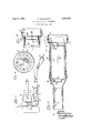
- Figure 1 illustrates a vacuum cleaner on which the attachment is mounted.
- Figure 2 is an enlarged sectional view of the invention.
- Figure 4 is a section on the line 4-4 of F i ure 2.
- FIG. 1 designates a conventional type of vacuum cleaner having a fan 2 therein driven by an electric motor 3,
- the dust distributing attachment is generally referred to by the ordinal 5, and consists of a tubular body or casing 6 one end 7 of which is enlarged to fit over the discharge connection 4 of the vacuum cleaner. Any suitable method of holding the body 6 on the discharge connection 4 may be employed. In the present instance the connection 4 has outwardly projecting pins 9 which engage bayonet slots 8 in the end 7 of the body 6.
- a transverse wall 10 or 10a is formed within the body 6 at the inner end of the enlarged portion 7 this wall may either be annular as shown at 10 in Figure 2 or continuous as illustrated at 10a in Figure 4. In either case the wall is provided with a plurality of perforations 11 arranged substantially in a circle adjacent the inner side of the Wall of the casing 6. Through the continuous wall 10a shown in Figure 4 other apertures 10?) are also provided.
- a cone-shaped fitting 12 having a pipe nipple 120 at its outer end.
- a flexible pipe 13 is arranged which terminates in a mouthpiece 14 having an outlet opening 14a.
- the latter should be preferably long and narrow so that when the mouthpiece is held against a crack in a floor or wall the powder ejected may be readily directed into the said crack.
- a removable cartridge 15 is provided in which insect powder is placed, in and 16 denotes a lid on the cartridge which may be removed for filling purposes.
- the end 15a of the cartridge is spaced from the transverse wall 10, or 1001, either by the projecting ends 17a of the springs 17 as shown in Figure 2, or by the annular extension 156 on the cartridge 15 as shown in F igure 4. Through the end 15a a few openings 18 are provided.
- the lid 16 of the cartridge has a number of holes 19 through it.
- arms 20 may be provided on the lid to engage the inner side of the cone-shaped fitting 12. These arms 20, when employed, alsoassist in holding the front portion of the cartridge central within the casing.
- Air is blown through the connection 4 of the vacuum cleaner and enters the enlarged portion 7 of the body; most of it passing around the exterior o1 the cartridge since the arms and spring 17a exhibit only a small obstructing effect.
- the insect powders are mostly very light and fiut'fy compositions as witness Paris-green, calcium arsenate, hellebore, lycopodium, pyreth-um, etc., and the effect of the air pressure is to pile the entire mass of powder against the further end of the receptacle, after which no further "air can pass through the receptacle itself.
- the air stream can and does continue topass treely around the outside of the receptacle and the constriction of the shape of the casing just beyond the further end of that receptacle causes a swirling and eddying of the air at this point which assists the pressure behind in removing a graduated supply of this powder from the apertures 19; and this edect is substantially aided and facilitated and increased by the vibration always communicated from a rapidly rotating fan 2 to the chamber to which this casing is rigidlyattached.
- the rate of feed of the powder into the air stream remains constant so long any powder remains in the receptacle or cartridge.
- An exterminating attachment comprising a hollow casing having transverse aperture d walltherein, a cartridge in said casing of lesser diameter thanthe latter, springs longitudinally arranged on the peripheryoi' said cartridge having outwardly flexed portions'to engage the casing bore and hold the cartridge "substantially concentric therein, the apertures in the transverse wall opening into the annular space formed b'etween'the periphery of the cartridge and the casing bore, a lid having holes therethrough on the end of said cartridge remote from said transverse wall, a cone-shaped fitting on said cas ing around said cover, arms on said lid hearing againstthe'inside of said cone-shaped fitting, meansfor spacing the end of the cartridge remote from the lid from the transverse wall, openings through the end of the cartridgeremote from the lid, means for admitting air through said transverse wall to said openings, a flexible discharge pipe on saidfitti'ng, a mouthpiece on said discharge pipe, and means on the end of the casing remote from the fitting
- a dust distributing nozzle comprising a ly cylindrical casing made in longitudinally separable parts and having at one end an 'axialoutlet mouth-and at the other end an axial inlet connection, a cylindrical cartridge in said casing of, greater diameter thansaid mouth or inlet and smaller diameter thanthe casing bore and means for spacing the side wall of said cartridge from 'the side wall Q5 of said casing, said casing having imperiorate side walls and foraminous end walls the space between said sidewalls-being atal] times in 'free communication with both said inletand said outlet.
- a cartridgeto receive apulverulent'material having an imperforate's'ide wall and opposed foraminous end w'allsi'n 'combinationwith a chamber member loosely receiving said 'c'ar tridge and spaced-"from its sidewalls'and having provisions for the longitudinal passage of aerifo'rm fluid theret11rough,ipast'the exterior of saideartridge,
- An 'e'zite'rminating attachment fco'm'p'rising ahollow metallic casingfqrmed'forettachmnt to the outletneck of an electric i' aciuini'cle'aner, meansfor securing-said ing "to said cleaner, a hose leading "from the casing, and a powder containing cartridge 1-:
Description
April 5, 1932. o. HOELSCHER DUST DISTRIBUTING ATTACHMENT Filed March 11. 1929 INVENTOR BY OZZ'o oeZsc7ze z l ATTORNEY" Patented Apr. 5, 1932 UNITED STATES OTTO HOELSGHER, OF DETROIT, MICHIGAN DUST DISTRIBUTING ATTACHMENT Application filed March 11, 1929. Serial No. 346,042.
This invention relates to improvements in dust distributing attachment, and, in its preferred form, consists in an attachment adapted to be mounted on a vacuum cleaner,
flthough it may also be utilized in connection with any other mechanism by which an air blast is produced.
It is an object of the invention to provide a dust distributing attachment with which insect powder may be discharged not merely onto floors and walls, but which discharges the powder with such velocity that it is dispersed through cracks into the spaces between floors and walls where cockroaches and other vermin live and breed.
Another object of the invention is to provide a dust distributing attachment which is simple and cheap to manufacture and can be made to fit any one make of vacuum cleaner or other air blast producing mechanism.
With these and other objects and advantages in view which will become apparent as the specification proceeds, the invention is hereinafter more fully described with the aid of the accompanying drawings, in which:
Figure 1 illustrates a vacuum cleaner on which the attachment is mounted.
Figure 2 is an enlarged sectional view of the invention.
Figure 3 shows a slight modification, and
Figure 4 is a section on the line 4-4 of F i ure 2.
ferring to the drawings, 1 designates a conventional type of vacuum cleaner having a fan 2 therein driven by an electric motor 3,
and a discharge connection 4 from the fan through which air is blown.
The dust distributing attachment is generally referred to by the ordinal 5, and consists of a tubular body or casing 6 one end 7 of which is enlarged to fit over the discharge connection 4 of the vacuum cleaner. Any suitable method of holding the body 6 on the discharge connection 4 may be employed. In the present instance the connection 4 has outwardly projecting pins 9 which engage bayonet slots 8 in the end 7 of the body 6. A transverse wall 10 or 10a is formed within the body 6 at the inner end of the enlarged portion 7 this wall may either be annular as shown at 10 in Figure 2 or continuous as illustrated at 10a in Figure 4. In either case the wall is provided with a plurality of perforations 11 arranged substantially in a circle adjacent the inner side of the Wall of the casing 6. Through the continuous wall 10a shown in Figure 4 other apertures 10?) are also provided.
Detachably arranged on the other end of the body or casing 6 is a cone-shaped fitting 12 having a pipe nipple 120 at its outer end. On the latter a flexible pipe 13 is arranged which terminates in a mouthpiece 14 having an outlet opening 14a. The latter should be preferably long and narrow so that when the mouthpiece is held against a crack in a floor or wall the powder ejected may be readily directed into the said crack.
In the body 6 a removable cartridge 15 is provided in which insect powder is placed, in and 16 denotes a lid on the cartridge which may be removed for filling purposes. On the sides of the cartridge, which is smaller than the bore of the casing 6, a plurality of outwardly flexed springs 17 are longitudinally arranged. These springs engage the inner surface of the body or casing 6 and hold the cartridge substantially concentric with the casing and spaced from the sides of the latter. The end 15a of the cartridge is spaced from the transverse wall 10, or 1001, either by the projecting ends 17a of the springs 17 as shown in Figure 2, or by the annular extension 156 on the cartridge 15 as shown in F igure 4. Through the end 15a a few openings 18 are provided.
The lid 16 of the cartridge has a number of holes 19 through it. In order to prevent both accident-a1 disengagement of the lid from its cartridge and to hold the latter against longitudinal movement in the casing arms 20 may be provided on the lid to engage the inner side of the cone-shaped fitting 12. These arms 20, when employed, alsoassist in holding the front portion of the cartridge central within the casing.
It is believed that the operation of the device will be readily understood from the foregoing, briefly it is as follows: Air is blown through the connection 4 of the vacuum cleaner and enters the enlarged portion 7 of the body; most of it passing around the exterior o1 the cartridge since the arms and spring 17a exhibit only a small obstructing effect. The insect powders are mostly very light and fiut'fy compositions as witness Paris-green, calcium arsenate, hellebore, lycopodium, pyreth-um, etc., and the effect of the air pressure is to pile the entire mass of powder against the further end of the receptacle, after which no further "air can pass through the receptacle itself. However, the air stream can and does continue topass treely around the outside of the receptacle and the constriction of the shape of the casing just beyond the further end of that receptacle causes a swirling and eddying of the air at this point which assists the pressure behind in removing a graduated supply of this powder from the apertures 19; and this edect is substantially aided and facilitated and increased by the vibration always communicated from a rapidly rotating fan 2 to the chamber to which this casing is rigidlyattached. As a result of these actions the rate of feed of the powder into the air stream remains constant so long any powder remains in the receptacle or cartridge.
WVhile in the foregoing the preferred embodiments of the invention have been described and shown, it is understood that the invention ;is subject to such further modifications as'fall within the scopeof the appended claims; and it is further understood that the invention may be utilized in combination with any type of air blast mechanism.
What I desire to secure by Letters Paten and claim as my invention is:
1. An exterminating attachment comprising a hollow casing having transverse aperture d walltherein, a cartridge in said casing of lesser diameter thanthe latter, springs longitudinally arranged on the peripheryoi' said cartridge having outwardly flexed portions'to engage the casing bore and hold the cartridge "substantially concentric therein, the apertures in the transverse wall opening into the annular space formed b'etween'the periphery of the cartridge and the casing bore, a lid having holes therethrough on the end of said cartridge remote from said transverse wall, a cone-shaped fitting on said cas ing around said cover, arms on said lid hearing againstthe'inside of said cone-shaped fitting, meansfor spacing the end of the cartridge remote from the lid from the transverse wall, openings through the end of the cartridgeremote from the lid, means for admitting air through said transverse wall to said openings, a flexible discharge pipe on saidfitti'ng, a mouthpiece on said discharge pipe, and means on the end of the casing remote from the fitting for attaching ablast mechanism thereto.
A dust distributing nozzle comprising a ly cylindrical casing made in longitudinally separable parts and having at one end an 'axialoutlet mouth-and at the other end an axial inlet connection, a cylindrical cartridge in said casing of, greater diameter thansaid mouth or inlet and smaller diameter thanthe casing bore and means for spacing the side wall of said cartridge from 'the side wall Q5 of said casing, said casing having imperiorate side walls and foraminous end walls the space between said sidewalls-being atal] times in 'free communication with both said inletand said outlet.
4. In a dust distributing attachmend; a cartridgeto receive apulverulent'material having an imperforate's'ide wall and opposed foraminous end w'allsi'n 'combinationwith a chamber member loosely receiving said 'c'ar tridge and spaced-"from its sidewalls'and having provisions for the longitudinal passage of aerifo'rm fluid theret11rough,ipast'the exterior of saideartridge,
5. An 'e'zite'rminating attachment fco'm'p'rising ahollow metallic casingfqrmed'forettachmnt to the outletneck of an electric i' aciuini'cle'aner, meansfor securing-said ing "to said cleaner, a hose leading "from the casing, and a powder containing cartridge 1-:
carried by said litting and adapted underinfluence of the vibration of said cleaner 'to deliver powder gradually iiit'o'the air stream.
OTTO HO ELSCH ER.
Priority Applications (1)
| Application Number | Priority Date | Filing Date | Title |
|---|---|---|---|
| US346042A US1852522A (en) | 1929-03-11 | 1929-03-11 | Dust distributing attachment |
Applications Claiming Priority (1)
| Application Number | Priority Date | Filing Date | Title |
|---|---|---|---|
| US346042A US1852522A (en) | 1929-03-11 | 1929-03-11 | Dust distributing attachment |
Publications (1)
| Publication Number | Publication Date |
|---|---|
| US1852522A true US1852522A (en) | 1932-04-05 |
Family
ID=23357677
Family Applications (1)
| Application Number | Title | Priority Date | Filing Date |
|---|---|---|---|
| US346042A Expired - Lifetime US1852522A (en) | 1929-03-11 | 1929-03-11 | Dust distributing attachment |
Country Status (1)
| Country | Link |
|---|---|
| US (1) | US1852522A (en) |
Cited By (2)
| Publication number | Priority date | Publication date | Assignee | Title |
|---|---|---|---|---|
| US2596011A (en) * | 1948-07-17 | 1952-05-06 | Allied Chem & Dye Corp | Dust gun |
| US4553698A (en) * | 1983-02-07 | 1985-11-19 | Parker Pest Control | Pneumatic pesticide duster for treatment of structures |
-
1929
- 1929-03-11 US US346042A patent/US1852522A/en not_active Expired - Lifetime
Cited By (2)
| Publication number | Priority date | Publication date | Assignee | Title |
|---|---|---|---|---|
| US2596011A (en) * | 1948-07-17 | 1952-05-06 | Allied Chem & Dye Corp | Dust gun |
| US4553698A (en) * | 1983-02-07 | 1985-11-19 | Parker Pest Control | Pneumatic pesticide duster for treatment of structures |
Similar Documents
| Publication | Publication Date | Title |
|---|---|---|
| BRPI0904471A2 (en) | dome-activated sprayer pump | |
| US1965765A (en) | Vacuum cleaner | |
| US2759228A (en) | Vacuum cleaner scenting attachment | |
| US3963178A (en) | Sprayer nozzle | |
| US1071620A (en) | Fly-catching apparatus. | |
| ITUB20155280A1 (en) | Distributor of material for agricultural machinery. | |
| US1852522A (en) | Dust distributing attachment | |
| US3684176A (en) | Pulsation impact spray nozzle | |
| US2611992A (en) | Engine exhaust operated fluent material distributor | |
| US1561039A (en) | Spraying apparatus | |
| US2577025A (en) | Foam nozzle attachment for spray guns | |
| US947726A (en) | Fumigating attachment. | |
| US2937802A (en) | Vacuum producing and conveying means | |
| US2540695A (en) | Fuel economizer and air cleaner for motor vehicles | |
| US926070A (en) | Dust-collector. | |
| US1748087A (en) | Renovating and oxygenizing device | |
| US1497540A (en) | Insect trap | |
| US1835511A (en) | Device for renovating feathers and the like | |
| US1808281A (en) | Air supply device | |
| US2564058A (en) | Insecticide duster | |
| US2589213A (en) | Nozzle for dry powder extinguishers | |
| US1661895A (en) | Cigar and cigarette holder | |
| US1554991A (en) | Powder dispenser | |
| US337943A (en) | Clabence a | |
| US1237111A (en) | Nozzle. |