US1853848A - Adjustable chair - Google Patents
Adjustable chair Download PDFInfo
- Publication number
- US1853848A US1853848A US372118A US37211829A US1853848A US 1853848 A US1853848 A US 1853848A US 372118 A US372118 A US 372118A US 37211829 A US37211829 A US 37211829A US 1853848 A US1853848 A US 1853848A
- Authority
- US
- United States
- Prior art keywords
- chair
- seat
- arm
- supporting
- arms
- Prior art date
- Legal status (The legal status is an assumption and is not a legal conclusion. Google has not performed a legal analysis and makes no representation as to the accuracy of the status listed.)
- Expired - Lifetime
Links
Images
Classifications
-
- A—HUMAN NECESSITIES
- A47—FURNITURE; DOMESTIC ARTICLES OR APPLIANCES; COFFEE MILLS; SPICE MILLS; SUCTION CLEANERS IN GENERAL
- A47D—FURNITURE SPECIALLY ADAPTED FOR CHILDREN
- A47D1/00—Children's chairs
- A47D1/10—Children's chairs capable of being suspended from, or attached to, tables or other articles
- A47D1/103—Children's chairs capable of being suspended from, or attached to, tables or other articles attachable to adult's chairs
Definitions
- This invention pertains to van article f manufacture and to certain component parts thereof, ⁇ particularly as embodied in a chair or seat suitable to be attached to various sup# "325 porting structures. More particularly it is exemplified in an adjustable chair adapted to be attached to a variety of other seats.
- the chair is reducible, by folding, to relatively small dimensions. Also in i0 the :same or other forms it is convertible into a swing seat, or adaptable t'o different types of attachmentto a supporting structure.
- ⁇ A salient object ofthe invention is to provide such an attachable chair as may be sustained'bythe seat of larger'chairs without imposing any'considerablestrain on the back of the larger chair.
- Another obj ect is to support an v attached chair without regard to the height or width or configuration of the back 2@ of the larger chair.
- lYet another Aobject is to obtain vertical adjustments of the supported seat without changesof the supports of the chair as a whole.
- Another Object is to pro- Y i d vide a supporting member for the seat proper 42"that will be the means of adjusting they seat vertically Vand will also serve as a pivoting memberby which the seat may be adjusted angularly or be rotated to a folded position.
- Another object is to provide an adjustable,
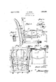
- Fig. 1 is a vertical section of the auxiliary chair proper with a side view of a supporting folding'seat that is susceptible of large scale bodiment shown there is however sufficient chair having one back member broken away.
- Fig. 2 is a front elevation of therauniliary chair supported by a larger chair.
- Fig. Si s a plan view ofthe chair witha k supporting structure anda portion ofthe se- 65 curing means in section. j
- Fig. 1- is a detail in side view of the securf ing means, and of the fastening for a side arm.
- Fig. 5 is a detail in section ofthe top df v Y the chair back with means adaptableto differenttypes of devices for suspending vthe chair.
- j l fr Fig. 6 is one form ofsupporting hook.V l;
- this auxiliary chair comprises a generally vertically l,disposed back. member 11, The lower part of this 'member is recessed for-a portion of its length, and over this recesslis secured aplate slotted at 12 and notched with a desirable number of. notches 13. It will be '5,0 understood that the invention is not restricted as to the number or shape of the back member,
- each of the two arms 19 snown comprises a straight portion and a curved portion, the latter normally being adjustable to bear forward against'the back of the supporting chair in response to the tendency to forward tilting of the auxiliary chair.
- this straight portion of arm through a coil spring 21, which spring is re tained on the arm 19 by an enlargement at the end thereof.
- the outer end of the spring engages a plate 22 on the outer side of the member 11 of the auxiliary chair so that while the arms 19 may be pulled out for engaging the support 20, on being re- Y leasedthey simply will be retracted to resting position.
- two arms 19 and their springs 21 are enclosed in a tubular element 23 between the corner members 11.
- a locking structure is provided for them.
- this is shown as a cam arm 211 on the side member 11, rotatable to wedge the arm 19 against turning.
- cushion members 2e' such as rubber pads on the bottoms of the legs 11; also rubber tubing over the curved portion o-f the side arms 19.
- this auxiliary chair is not limited to being attached to one larger chair, but that a particularly useful application will be in sustaining it between two other chairs.
- parents occupying ⁇ two larger chairs may seat a child between them, resting the supporting members 11 of the childs chair upon each of the larger chairs and engaging the sustaining side arm 19 behind the backs of the two larger chairs.
- the structure of the'supporting chair thus is of minimal importance.
- light chairs with curved backs are justas effective supports as heavy straight backed ones.
- sides may be provided having certain features that make for safety as well as for compaetness'.
- Figs. 1 and 2 it is seen that these sides comprise a base member 25, secured by inner hinges to the 'seat 17. From Fig. 3 it is clear that the bac-k of a top rail,
- a tray 29 A is provided., so arranged as to prevent undesirable folding of the armswhen theboltsZS are retracted.
- V The edges of the tray are tongued', and the side'rail 27 is' pros vided wit i grooves to receive-the tray in sliding engagementfrom the'front.
- 'The front endsof rail 27 are provided with deformed or eccentric buttons r30, which may be turned to retain thetray in its inserted'position. In Fig. 2 one such button,.with thumb grips, is shown. in position to permit the withdrawal of the tray and the other button turned to closed position.
- the 4chair is provided with a storage space made possible by flanging the horizontal arm 14 inwardly and mountingit in spaced relation to the seat 17'.
- buttons to retain the tray may also be provided here if desired.
- the tops of, the vertical members 11 maybe. fashioned to receive hook elements.
- a metal plate 301s secured to the top by portions extending downwardly and engaging the top by rivets yor the like.
- the chair With this typeof fastening the chair may besuspended by ropes from bolts 31 and from similar bolts 33 at the bottom to form a swing, forV example. removing bolts 31 and substituting a longer hook member 34, ofthe type shown Vin Fig. 6, the chair may be suspended from other supporting elements, for example from the back of an auto seat, A Where this longer hook is employed the vertical members preferably will be bored toreceive the end' of the hook 311- for a suitable distance below the plate. It is evident that in certain cases the bushing 32 may be dispensed with and mem-y bers 31 or 34 of suitable'diameter be secured directly to the top.
- the chair is readily adjusted to accommodate a person of given height, say a baby of less than a year.
- the seat 17 is raised to its highest position by engaging the head 15 of supporting arm 14 in the highest notch 13. As long as this elevation is suitable, it is retained; but during that time the chair may be folded and carried about or unfolded as desired.
- the seat is lowered by sliding the head 15 down the slot12 to a lower notch.
- the head 15 acts as a pivot for folding the seat or for sustaining the occupant.
- the seat may be folded by releasing the thumb bolts 28 ofthe sideV rail 27 and, with tray 29 slid beneathfthe seat, turning the sides in upon the seat, then folding this assemblage to the back ⁇ about the pivot 15. If desired the chair may be left 1n that position, in engagement by the side'hooks 19 with a supporting chair, and yet leaving space fork an adult in the larger chair. Or
- the chair may be set up quickly by turning down the seat, rais-: v
- the engaging armsl 19 as quickly may be sprung out and locked behind the sides of theiry support, such as the sides of a chair, or of two chairs where the auxiliary chair is placed between two chairs.
- a portable folding chair adapted for principal support at the rear thereof, com- Vtaining arms retractably mounted from the l prising a rear leg containing a vertical series f Abracket for bearing in raised position Vagainst the leg and bracket to prevent swinging the bracket upwardly and in folded position affording space for the bracket to be rotated upwardly for disengagement from anotch.
- a portable folding chair adapted for principal support at the rear thereof, comprising a rear leg containing a vertical series of open notches, a seat-supporting bracket 'adjustably' mounted on' the leg forwardly thereof by a pivotal, cantilever support co1n.y prising a lug extending laterally from the Vbracket to engage any selected lnotch and a projection extending laterally from.
- bracket to bear against thechair leg means controlling adjustment of the seat along the series of notches, comprising a rigid arm foldably mounted above the bracket for bearing in raised position against the leg and bracket to prevent swinging the bracket up- ⁇ wardly and in foldedposition affording space forthe bracket to be rotated upwardly for disengagement from a notch, and apa-ir of rerear leg in opposed relation to each other 'across the rear ofthe chair, each arm terj minatmg outwardly in an enlarged hookfor.
Description
April l2, 1932. E. cRoss 1,853,848
l ADJUSTABLE CHAIR Filed Ju'n e 19, 1929 Patented Apr. 12, 1932 r UNITED -fsTATEs EARL caoss, or RENO, NEVADA ADaUsTABL'E CHAIR I Application iledJune 19, 1929. Serial No. 372,118;
, This invention pertains to van article f manufacture and to certain component parts thereof,` particularly as embodied in a chair or seat suitable to be attached to various sup# "325 porting structures. More particularly it is exemplified in an adjustable chair adapted to be attached to a variety of other seats. In
certain forms the chair is reducible, by folding, to relatively small dimensions. Also in i0 the :same or other forms it is convertible into a swing seat, or adaptable t'o different types of attachmentto a supporting structure.
`A salient object ofthe invention is to provide such an attachable chair as may be sustained'bythe seat of larger'chairs without imposing any'considerablestrain on the back of the larger chair. Another obj ect is to support an v attached chair without regard to the height or width or configuration of the back 2@ of the larger chair. lYet another Aobject is to obtain vertical adjustments of the supported seat without changesof the supports of the chair as a whole. Another Objectis to pro- Y i d vide a supporting member for the seat proper 42"that will be the means of adjusting they seat vertically Vand will also serve as a pivoting memberby which the seat may be adjusted angularly or be rotated to a folded position. Another object is to provide an adjustable,
productionv as a result of the simplification herein presented and of the introduction of novel features of co-.operation in the assembled structure.l Other objects and advantages will appear with an understanding of the invention as set forth in the accompanying illustrativeembodiments and drawings and as. particularly pointed out inlthe appended claims.
"llt- In order to illustrate this invention fully sothat others Vmay understand its practices, certain embodiments are described which co-nstitute present` preferred forms of various features of the invention. Such illustrations are not intended to be restrictive however. Reference maybehad to the accompanying diagrammatic drawings forming part of this specification, in which:
Fig. 1 is a vertical section of the auxiliary chair proper with a side view of a supporting folding'seat that is susceptible of large scale bodiment shown there is however sufficient chair having one back member broken away. Fig. 2 is a front elevation of therauniliary chair supported by a larger chair. Fig. Sis a plan view ofthe chair witha k supporting structure anda portion ofthe se- 65 curing means in section. j
Fig. 1- is a detail in side view of the securf ing means, and of the fastening for a side arm.
Fig. 5 is a detail in section ofthe top df v Y the chair back with means adaptableto differenttypes of devices for suspending vthe chair. j l fr Fig. 6 is one form ofsupporting hook.V l; By Areference to Fig. 1 it is apparent 4that this auxiliary chair comprises a generally vertically l,disposed back. member 11, The lower part of this 'member is recessed for-a portion of its length, and over this recesslis secured aplate slotted at 12 and notched with a desirable number of. notches 13. It will be '5,0 understood that the invention is not restricted as to the number or shape of the back member,
though twosuch are shown and as shown are positioned at the two rear corners of the chair. Neither is the invention restricted to thertype ofV slotted and notched portion, for it is apparent that it may be some integral portion of the rear member, or that other pivot adj ustment maybe provided. In thepreferred em-` space for movement in the slot 12 of the shank of the head 15 of a pivoted arm 14. The rear of this'arm 14: preferably slides in the recessed v f Y portion of the back. This arm, or arms, 14; preferably is curved downwardly from the rear and then normally extended horizontally as shown in Fig. 1. It thus supports side Vpieces 16, upon which rests the seat 17. By .engagement ofthe projectionof the head 15 in 'one notch or another the seat is adjusted 0 vertically; while by rotation of the arm the seat is folded tothe back or unfolded without ldisturbing its vertical adjustment. With the back members 11 forming legs forthe chair it is apparent that the weight of an occupant j 5 Vis supported primarily by these legs. Also it is apparent that vertical adjustment of the seat is relative to the seat 18 of a supporting chair upon which the auxiliary chair ordinarily will bear. .NTO supply a stop to the( 1.00
tendency of the arm 111 to rotate downwardly, preferably the side member 16 to which 1e is secured abuts at the rear as shown against the back 11 when the arm 14. is horizontal. Other types of stop howeverI may be contemplated within the broader scope of this invention.
The upper portion of the back members 11 carries a side retaining arm 19, and this preferably is readily adjustable to grip the back of the supporting chair 20. In'the illustrative embodiment, each of the two arms 19 snown comprises a straight portion and a curved portion, the latter normally being adjustable to bear forward against'the back of the supporting chair in response to the tendency to forward tilting of the auxiliary chair. Freterably this straight portion of arm through a coil spring 21, which spring is re tained on the arm 19 by an enlargement at the end thereof.Y As shown in Fig. 3, the outer end of the spring engages a plate 22 on the outer side of the member 11 of the auxiliary chair so that while the arms 19 may be pulled out for engaging the support 20, on being re- Y leasedthey simply will be retracted to resting position. As is shown, two arms 19 and their springs 21 are enclosed in a tubular element 23 between the corner members 11.
In order to assure a minimum of undesin able slipping of the arms 19, and to assist them to be adjusted to different forms of suporting structure, a locking structure is provided for them. In Fig. /1 this is shown as a cam arm 211 on the side member 11, rotatable to wedge the arm 19 against turning.
As it may be desired to eliminate noise or to avoid marring other furniture, there are provided appropriate cushion members 2e', such as rubber pads on the bottoms of the legs 11; also rubber tubing over the curved portion o-f the side arms 19.
From the description thus far given it. will become apparent that this auxiliary chairis not limited to being attached to one larger chair, but that a particularly useful application will be in sustaining it between two other chairs. For example, parents occupying` two larger chairs may seat a child between them, resting the supporting members 11 of the childs chair upon each of the larger chairs and engaging the sustaining side arm 19 behind the backs of the two larger chairs. The structure of the'supporting chair thus is of minimal importance. For example, light chairs with curved backs are justas effective supports as heavy straight backed ones.
In order to adapt this auxiliary chair further to accommodate young children, sides may be provided having certain features that make for safety as well as for compaetness'. By reference to Figs. 1 and 2 it is seen that these sides comprise a base member 25, secured by inner hinges to the 'seat 17. From Fig. 3 it is clear that the bac-k of a top rail,
19 extends' sustained by the base member upon vertical elements 26, extends beyond the inner edge of leg 11 so that its outward swing is limited thereby. Thus a substantial stop is provided for inadvertent opening of the folding sides beyond their vertical position. In order however that these sides may reach a vertical position their rear outer corners are'recessed to `clear the members 11, as is shown in Fig. 3. Andin order that inward swinging of the sides may be under simple, positive control they preferably are provid-ed with suitable catches to engage legs 11. In the form shown in Figs. 8 and-ll, these simply are slide bolts 28 projectingV along the outer sides ofmembers 11 when the arms 27 are raised tothe vertical. 'In'Fig V2, the folded position of the sides upon theseatis shown in dotted lines. It is evident'thepositionof these. arms betweenv the bracket 14 and the rear leg- 11 controls the upward rotation of the 4bracket lll for disengagement from any notch 13.
A tray 29 Ais provided., so arranged as to prevent undesirable folding of the armswhen theboltsZS are retracted. VThe edges of the tray are tongued', and the side'rail 27 is' pros vided wit i grooves to receive-the tray in sliding engagementfrom the'front. 'The front endsof rail 27 are provided with deformed or eccentric buttons r30, which may be turned to retain thetray in its inserted'position. In Fig. 2 one such button,.with thumb grips, is shown. in position to permit the withdrawal of the tray and the other button turned to closed position.
Further withreference to the tray, the 4chair is provided with a storage space made possible by flanging the horizontal arm 14 inwardly and mountingit in spaced relation to the seat 17'. Thus there are supports for the 'traylbetween the `elements 16 to secureiit ,in
any pesition of the seat.. Suitable buttons to retain the tray may also be provided here if desired.
In order to. sustain the chair from 'other types of support, the tops of, the vertical members 11 maybe. fashioned to receive hook elements. In one form, as shown in Figs. 1 and 5, a metal plate 301s secured to the top by portions extending downwardly and engaging the top by rivets yor the like. The
plate is drilled, preferably in its front half,
and suitably threadedto receive eye bolt 31,
and. bushing- 82. With this typeof fastening the chair may besuspended by ropes from bolts 31 and from similar bolts 33 at the bottom to form a swing, forV example. removing bolts 31 and substituting a longer hook member 34, ofthe type shown Vin Fig. 6, the chair may be suspended from other supporting elements, for example from the back of an auto seat, A Where this longer hook is employed the vertical members preferably will be bored toreceive the end' of the hook 311- for a suitable distance below the plate. It is evident that in certain cases the bushing 32 may be dispensed with and mem- y bers 31 or 34 of suitable'diameter be secured directly to the top. In operation the chair is readily adjusted to accommodate a person of given height, say a baby of less than a year. The seat 17 is raised to its highest position by engaging the head 15 of supporting arm 14 in the highest notch 13. As long as this elevation is suitable, it is retained; but during that time the chair may be folded and carried about or unfolded as desired. When an older child is to be accommodated, the seat is lowered by sliding the head 15 down the slot12 to a lower notch. At this elevation, as at others, the head 15 acts as a pivot for folding the seat or for sustaining the occupant. With a child of yet greater heightthe s eatis loweredfur-A ther to the proper notch. Thus the one chair will accommodate a child from thetime it is first able to sit up until it is of such age that its height permits it to use an ordinary chair advantageously.
95. The chair having been adjusted by elevatl ing the seatas desired, the seat may be folded by releasing the thumb bolts 28 ofthe sideV rail 27 and, with tray 29 slid beneathfthe seat, turning the sides in upon the seat, then folding this assemblage to the back` about the pivot 15. If desired the chair may be left 1n that position, in engagement by the side'hooks 19 with a supporting chair, and yet leaving space fork an adult in the larger chair. Or
it may be removed entirely from the larger chair, before or after folding.
From folded position the chair may be set up quickly by turning down the seat, rais-: v
ing the side arms and locking them simply 40 by pushing the bolts 28backwards.` The engaging armsl 19 as quickly may be sprung out and locked behind the sides of theiry support, such as the sides of a chair, or of two chairs where the auxiliary chair is placed between two chairs.
This description of the best practice and construction now known under this invention is presented in accordance with the patent statutes. However, in referring to these illustrative embodiments' of this invention, restrictions have not been implied thereby. One particular structure was made of wood with an angle iron support and restricted to a weight of about live pounds. However Wood need not necessarily be used, as it will be within ordinary skill in lthe art to construct this chair of suitable metal parts. Also various fea-tures may be omitted or modified without altering the scope of this invention.'-
It is intended to claim broadly such features of this invention as the prior art permits. Accordingly, Y Y' What is claimed is:
1. A portable folding chair adapted for principal support at the rear thereof, com- Vtaining arms retractably mounted from the l prising a rear leg containing a vertical series f Abracket for bearing in raised position Vagainst the leg and bracket to prevent swinging the bracket upwardly and in folded position affording space for the bracket to be rotated upwardly for disengagement from anotch. i 2. A portable folding chair adapted for principal support at the rear thereof, comprising a rear leg containing a vertical series of open notches, a seat-supporting bracket 'adjustably' mounted on' the leg forwardly thereof by a pivotal, cantilever support co1n.y prising a lug extending laterally from the Vbracket to engage any selected lnotch and a projection extending laterally from. the
bracket to bear against thechair leg, means controlling adjustment of the seat along the series of notches, comprising a rigid arm foldably mounted above the bracket for bearing in raised position against the leg and bracket to prevent swinging the bracket up-` wardly and in foldedposition affording space forthe bracket to be rotated upwardly for disengagement from a notch, and apa-ir of rerear leg in opposed relation to each other 'across the rear ofthe chair, each arm terj minatmg outwardly in an enlarged hookfor.
external engagement to prevent the chair from tilting, and a spring engaging the in v 205 -ner portion of each arm and mounted for drawing t-he hook toward the leg.
Y EARL CROSS.
l tic
Priority Applications (1)
| Application Number | Priority Date | Filing Date | Title |
|---|---|---|---|
| US372118A US1853848A (en) | 1929-06-19 | 1929-06-19 | Adjustable chair |
Applications Claiming Priority (1)
| Application Number | Priority Date | Filing Date | Title |
|---|---|---|---|
| US372118A US1853848A (en) | 1929-06-19 | 1929-06-19 | Adjustable chair |
Publications (1)
| Publication Number | Publication Date |
|---|---|
| US1853848A true US1853848A (en) | 1932-04-12 |
Family
ID=23466778
Family Applications (1)
| Application Number | Title | Priority Date | Filing Date |
|---|---|---|---|
| US372118A Expired - Lifetime US1853848A (en) | 1929-06-19 | 1929-06-19 | Adjustable chair |
Country Status (1)
| Country | Link |
|---|---|
| US (1) | US1853848A (en) |
Cited By (11)
| Publication number | Priority date | Publication date | Assignee | Title |
|---|---|---|---|---|
| US2533527A (en) * | 1948-07-02 | 1950-12-12 | John A Soltis | Baby's automobile seat |
| US2992854A (en) * | 1958-04-14 | 1961-07-18 | Berlin Daniel | Child's chair bracket suspension |
| US3144272A (en) * | 1961-12-04 | 1964-08-11 | Kamlet Lab | Baby seat between separate seats |
| US3190692A (en) * | 1964-03-02 | 1965-06-22 | Thomas J Collier | Child's safety seat for barber chair |
| US3338631A (en) * | 1965-12-30 | 1967-08-29 | Strolee Of California Inc | Infant's car seat |
| US4186961A (en) * | 1974-07-02 | 1980-02-05 | Buckeye International Inc. | Child car seating apparatus and method for assembling the same |
| US5346279A (en) * | 1993-02-18 | 1994-09-13 | Pecorella Michael N | Orthopedic appliance |
| US5836650A (en) * | 1997-06-13 | 1998-11-17 | Century Products Company | Car seat with height adjustment mechanism |
| US6019426A (en) * | 1998-01-21 | 2000-02-01 | Takata Corporation | Child seat |
| US6948219B2 (en) | 2002-05-31 | 2005-09-27 | Graco Children's Products Inc. | Latch system for child seat |
| US20130292984A1 (en) * | 2012-05-02 | 2013-11-07 | Lerado (Zhong Shan) Industrial Co., Ltd. | Chair with a backrest adjustment mechanism |
-
1929
- 1929-06-19 US US372118A patent/US1853848A/en not_active Expired - Lifetime
Cited By (11)
| Publication number | Priority date | Publication date | Assignee | Title |
|---|---|---|---|---|
| US2533527A (en) * | 1948-07-02 | 1950-12-12 | John A Soltis | Baby's automobile seat |
| US2992854A (en) * | 1958-04-14 | 1961-07-18 | Berlin Daniel | Child's chair bracket suspension |
| US3144272A (en) * | 1961-12-04 | 1964-08-11 | Kamlet Lab | Baby seat between separate seats |
| US3190692A (en) * | 1964-03-02 | 1965-06-22 | Thomas J Collier | Child's safety seat for barber chair |
| US3338631A (en) * | 1965-12-30 | 1967-08-29 | Strolee Of California Inc | Infant's car seat |
| US4186961A (en) * | 1974-07-02 | 1980-02-05 | Buckeye International Inc. | Child car seating apparatus and method for assembling the same |
| US5346279A (en) * | 1993-02-18 | 1994-09-13 | Pecorella Michael N | Orthopedic appliance |
| US5836650A (en) * | 1997-06-13 | 1998-11-17 | Century Products Company | Car seat with height adjustment mechanism |
| US6019426A (en) * | 1998-01-21 | 2000-02-01 | Takata Corporation | Child seat |
| US6948219B2 (en) | 2002-05-31 | 2005-09-27 | Graco Children's Products Inc. | Latch system for child seat |
| US20130292984A1 (en) * | 2012-05-02 | 2013-11-07 | Lerado (Zhong Shan) Industrial Co., Ltd. | Chair with a backrest adjustment mechanism |
Similar Documents
| Publication | Publication Date | Title |
|---|---|---|
| US3669492A (en) | Reclining car seat | |
| US1853848A (en) | Adjustable chair | |
| US3574872A (en) | Infant{3 s car bed | |
| US3940181A (en) | Adjustable hassock | |
| US3650560A (en) | Folding chair and table set | |
| US2137799A (en) | Folding chair | |
| US2545968A (en) | Collapsible chair having foldable armrests | |
| US2588754A (en) | Infant's feeding table | |
| US2540291A (en) | Combined chair and table | |
| US2971567A (en) | Children's high chair | |
| US2810428A (en) | Baby chair | |
| US2454118A (en) | Combination table and chair | |
| US822472A (en) | Baby-chair. | |
| US1943037A (en) | Folding chair | |
| US834383A (en) | Child's folding chair. | |
| US2689600A (en) | Portable armrest for automobile seats | |
| US1952216A (en) | Baby toilet cabinet | |
| US2646106A (en) | Hinge construction for elevating chair seats | |
| US2814333A (en) | Child's chair for use either within or outside of an automobile | |
| US1253241A (en) | Combined baby-chair and common chair. | |
| US1730895A (en) | Collapsible high chair | |
| US2179152A (en) | Convertible couch | |
| US2593750A (en) | Extensible seat for chairs | |
| US1384695A (en) | Combination-table | |
| US961311A (en) | Child's adjustable chair. |