US1854475A - Method for electrically charging fluids - Google Patents
Method for electrically charging fluids Download PDFInfo
- Publication number
- US1854475A US1854475A US426860A US42686020A US1854475A US 1854475 A US1854475 A US 1854475A US 426860 A US426860 A US 426860A US 42686020 A US42686020 A US 42686020A US 1854475 A US1854475 A US 1854475A
- Authority
- US
- United States
- Prior art keywords
- fluid
- particles
- dispersing
- field
- fuel
- Prior art date
- Legal status (The legal status is an assumption and is not a legal conclusion. Google has not performed a legal analysis and makes no representation as to the accuracy of the status listed.)
- Expired - Lifetime
Links
Images
Classifications
-
- F—MECHANICAL ENGINEERING; LIGHTING; HEATING; WEAPONS; BLASTING
- F02—COMBUSTION ENGINES; HOT-GAS OR COMBUSTION-PRODUCT ENGINE PLANTS
- F02M—SUPPLYING COMBUSTION ENGINES IN GENERAL WITH COMBUSTIBLE MIXTURES OR CONSTITUENTS THEREOF
- F02M21/00—Apparatus for supplying engines with non-liquid fuels, e.g. gaseous fuels stored in liquid form
-
- F—MECHANICAL ENGINEERING; LIGHTING; HEATING; WEAPONS; BLASTING
- F02—COMBUSTION ENGINES; HOT-GAS OR COMBUSTION-PRODUCT ENGINE PLANTS
- F02M—SUPPLYING COMBUSTION ENGINES IN GENERAL WITH COMBUSTIBLE MIXTURES OR CONSTITUENTS THEREOF
- F02M2700/00—Supplying, feeding or preparing air, fuel, fuel air mixtures or auxiliary fluids for a combustion engine; Use of exhaust gas; Compressors for piston engines
- F02M2700/12—Devices or methods for making a gas mixture for a combustion engine
-
- Y—GENERAL TAGGING OF NEW TECHNOLOGICAL DEVELOPMENTS; GENERAL TAGGING OF CROSS-SECTIONAL TECHNOLOGIES SPANNING OVER SEVERAL SECTIONS OF THE IPC; TECHNICAL SUBJECTS COVERED BY FORMER USPC CROSS-REFERENCE ART COLLECTIONS [XRACs] AND DIGESTS
- Y10—TECHNICAL SUBJECTS COVERED BY FORMER USPC
- Y10S—TECHNICAL SUBJECTS COVERED BY FORMER USPC CROSS-REFERENCE ART COLLECTIONS [XRACs] AND DIGESTS
- Y10S159/00—Concentrating evaporators
- Y10S159/26—Electric field
Definitions
- My invention relates to methods of electrically charging and treating fluid vapors and sprays and to apparatus for putting such methods into practical use.
- One of the objects of my invention is to provide a means and method for dispersing fluids, particularly fluid fuels.
- Figure 1 is a side elevation, partly in section, of one embodiment of my invention.
- Fig. 2 is a diagrammatic view, partly in sectional elevation, showing a circuit arrangement and one application of the invention.
- Fig. 3 is a diagrammatic view showing the device of Fig. 1 connected to a source of current, together with other details.
- a fluid may be reduced to the form of vapor or spray by subjecting the same to an inducing electrical field.
- I have found that where a jet of fluid issues under the influence of an inducing field of force the charge has the effect of forming the fluid into fine particles. This effect may be used either alone or in combination with deflecting means.
- Fig. 1 I have shown an embodiment by means of which the fluid may be dispersed by subjecting it to the influence of an electrostatic field.
- a 70 casing 25 which may be connected to a source of fluid by means of the screw threads 11 or 6. Fluid is discharged from the chamber provided by the casing 25 through the discharge openings 5, 5 in a path which is in the inducing field of an electrode 1, which is connected by means of a threaded member 3, and a conductor 12. to a source of high tension electricity.
- the conductor connecting the electrode with the source of electricity is preferably enclosed within an insulating member 4, while its position, together with that of the electrode, may be adjusted by means of set screw 7
- At 2 is an insulating sleeve enclosing the conducting member and a part of the electrode.
- the electrode 1 may of a type commonly used with violet ray machines, or the like. I contemplate, however, that any other suitable type or form of electrode may be substituted therefor and either a part or the whole enclosed by insulation where necessary.
- Such means as might include, or be associated with, a high frequency generator, or a transformer, or the like, may be employed to develop an electrostatic field for charging the vapor or spray.
- unidirectional current While an inducing field developed by an alternating current may be employed to charge the fluid, I have found it preferable to employ unidirectional current.
- a mechanical rectifier or a set of two, preferably four, kenotrons may be employed. With such apparatus both sides of the waves are made available for use. With one kenotron, however, one side of the waves is suppressed and one side made available.
- a simple arrangement for dispersing the fluid by means of unidirectional current may consist of a high potential generator of unidirectional current, conventionally shown at 24, which is connected by means of circuit 30 to conductor 12 and the device 25. Circuit 30 may, if desired, be provided with a switch element 27 and grounded at 28 and 29, or completed in any other suitable or convenient manner.
- the particle receives a charge and leaves the field before an opposing influence is set up.
- the particle receives a charge and leaves the field before an opposing influence is set up.
- the charges so carried will be of similar sign.
- Fig. 2 I have shown an arran ement by means of which the method may e employed for dispersing or atomizing fluid fuel employed in connection with a furnace.
- This arrangement provides a burner 19, having an orifice 22 opening into the furnace chamber (not shown), and an air supply inlet which may be connected, if desirable, to a source of air under pressure by means of the screw threads 20.
- the burner is connected to the wall 21 of the furnace by means of the screw threads 23.
- a low tension source of current 18 supplies current through circuit 14 to the primary winding of a high tension transformer 15, which, in turn, feeds the secondary circuit 18, which is connected to terminal 8 and conductor 12.
- Means are provided for opening or closing circuits 13 and 14:- by the switch elements 16 and 17 respectively.
- Figure 3 is a diagrammatic view of a side elevation of the device of Fig. 1, showing the same connected to a standard, and also showing the circuit connections, the same being as before described.
- the standard 26 is connected by means of the screw threads 10 to the casing 25.
- the standard which is shown partly in section, provides a supporting means whereby the device may be employed in electrical irrigation.
- any other suitable or convenient means may be substituted for the standard shown and connected, as by the screw threads, to the casing 25.
- the device may also be supported by the conduit supplying the fluid, in which case the standard would be unnecessary.
- vegetation may, when desired, be charged chemically with such substances as have been found to have a beneficial efl'ect, either in stimulating plant growth or by way of having an injurious eflect upon the fungus or insect peststo which the vegetation may be subject.
- a beneficial efl'ect By adding the electrical charge to the chemically charged fluid the chemical action is increased.
- the method of dispersing fluid fuel which consists in discharging the same in the form of one or more jets and applying electrical charges to the dispersed particles of similar sign and substantially equal value.
- the method of dispersing fluid fuel which consists in discharging the same in the form of one or more jets and so charging the unvaporized fluid that when the particles become detached. from the mass they carry electrical charges of such character that mutual repulsion is produced between them.
- the step in the method of dispersing liquid fuel which consists in so charging the particles that those cutting the same cross sectional plane at substantially the same time carry mutually repellent electrical charges of substantially equal value.
- the step in the method of dispersing liquid fuel which consists in so charging the particles that those traveling abreast carry electrical charges of like sign.
- the method of dispersing a fluid which consists in establishing an electrical field and discharging the fluid in the form of two or more jets into the field to apply electrical charges to the dispersed particles of similar sign and substantially equal value.
Description
April 1932 r E. E. LiTTLEFiELD 354, 5
METHOD FOR ELECTRICALLY CHARGING FLUIDS Filed Nov. 27. 1920 INVE Patented Apr. 19, 1932 UNITED STATES PATENT OFFICE METHOD FOR ELECTBIOALLY CHARGING FLUIDS Application filed November 27, 1920. Serial No. 426,860.
This ap lication is a continuation, in part, of an application filed by me October 24, 1916, Ser. No. 127,338, for an improvement in apparatus for electrically charging fluids, which application eventuated in Patent No. 1,360,654, Nov. 30, 1920. The application which eventmted in Patent No. 1,360,654, is a continuation of my former application filed March 10, 1909, Ser. No. 482,599, and the subjest-matter of the instant application is disclosed in the application filed March 10, 1909.
My invention relates to methods of electrically charging and treating fluid vapors and sprays and to apparatus for putting such methods into practical use.
One of the objects of my invention is to provide a means and method for dispersing fluids, particularly fluid fuels.
Other and further objects and advantages of the invention will appear to those skilled in the art upon consideration of the specification, drawings, and the appended claims.
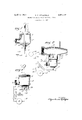
For a better understanding of the nature and Scope of my invention reference may be had to the following description and the accompanying drawings in which Figure 1 is a side elevation, partly in section, of one embodiment of my invention. Fig. 2 is a diagrammatic view, partly in sectional elevation, showing a circuit arrangement and one application of the invention. Fig. 3 is a diagrammatic view showing the device of Fig. 1 connected to a source of current, together with other details.
86 I have found that a fluid may be reduced to the form of vapor or spray by subjecting the same to an inducing electrical field. I have found that where a jet of fluid issues under the influence of an inducing field of force the charge has the effect of forming the fluid into fine particles. This effect may be used either alone or in combination with deflecting means.
While it would be desirable in many cases to use the fluidin a comparatively purer state increase the potential of a charge carried by the fluid.
I have employed this method to disperse fluids employed in the electrical treatment of vegetation. I have also employed the method to disperse, or atomize, liquid fuel employed in connection with furnaces and internal combustion engines. It has also been used for charging and dispersing fluids discharged from fountains.
As a further illustration of the scope of the invention it may be utilized for the generation of ozone to be supplied to the fuel using device. Instead of op osing combustion, this substance has been fbund to possess 66 properties favoring it.
In Fig. 1 I have shown an embodiment by means of which the fluid may be dispersed by subjecting it to the influence of an electrostatic field. To this end I have provided a 70 casing 25, which may be connected to a source of fluid by means of the screw threads 11 or 6. Fluid is discharged from the chamber provided by the casing 25 through the discharge openings 5, 5 in a path which is in the inducing field of an electrode 1, which is connected by means of a threaded member 3, and a conductor 12. to a source of high tension electricity. The conductor connecting the electrode with the source of electricity is preferably enclosed within an insulating member 4, while its position, together with that of the electrode, may be adjusted by means of set screw 7 At 2 is an insulating sleeve enclosing the conducting member and a part of the electrode. The electrode 1 may of a type commonly used with violet ray machines, or the like. I contemplate, however, that any other suitable type or form of electrode may be substituted therefor and either a part or the whole enclosed by insulation where necessary. Such means as might include, or be associated with, a high frequency generator, or a transformer, or the like, may be employed to develop an electrostatic field for charging the vapor or spray. While an inducing field developed by an alternating current may be employed to charge the fluid, I have found it preferable to employ unidirectional current. For this purpose either a mechanical rectifier or a set of two, preferably four, kenotrons may be employed. With such apparatus both sides of the waves are made available for use. With one kenotron, however, one side of the waves is suppressed and one side made available. I have found that for dispersing the fluid unidirectional current is superior to alternating current. A simple arrangement for dispersing the fluid by means of unidirectional current may consist of a high potential generator of unidirectional current, conventionally shown at 24, which is connected by means of circuit 30 to conductor 12 and the device 25. Circuit 30 may, if desired, be provided with a switch element 27 and grounded at 28 and 29, or completed in any other suitable or convenient manner.
, Theoretically considered and assuming thatthe conductor 12 is connected to a source of directcurrentan electrical field will form in the regionadjacent the electrode 1. If the field is one in which induction may take place and fluid froma .jet is discharged under the influence of the field the particles leaving the jet will carry electrical charges of one sign while the charges of the opposite sign will be given up to the jet, it being assumed that the electrostatic capacity of the jet is suflicient to absorb the charges of opposite sign. Since the particles leaving the'jet carry electrical charges of similar sign mutual repulsion or dispersion results.
Considering now afield in which the air is ionized or charged. it is'possible tocharge the particles of fluid by means of the ionized air. If the fluid particles, for instance, are exposed to contact with the ionized air electrical charges will be imparted to the former. Since the charges carried by the air particles are of similar sign and these are shared with the particles of fluid the charges imparted to the latter will be of similar sign.
. In the foregoing it has been assumed that the field is one produced by direct current. If now a field produced by alternating current is substituted for the former similar re- .sults may be obtained. An insulated particle of matter occupying a fixed position in an alternating field will receive first a charge of one sign and then a charge of opposite sign, but if the particle is passed rapidly through the field it will be found to possess a substantial charge after leaving the field. Ob-
. viously, the particle receives a charge and leaves the field before an opposing influence is set up. In substantially similar manner it is possible to charge particles of fluid or solid matter. Moreover. it is apparent that the charges so carried will be of similar sign.
In the two cases last considered it is obvious that mutual repulsion results. Vith reference to the "above compare the British patent to Diebold, No. 117.077. November 21, 1918.
In Fig. 2 I have shown an arran ement by means of which the method may e employed for dispersing or atomizing fluid fuel employed in connection with a furnace. This arrangement provides a burner 19, having an orifice 22 opening into the furnace chamber (not shown), and an air supply inlet which may be connected, if desirable, to a source of air under pressure by means of the screw threads 20. The burner is connected to the wall 21 of the furnace by means of the screw threads 23. By means of the screw threads 9 a combination is eflected between the device of Fig. 1 and the burner 19. A low tension source of current 18 supplies current through circuit 14 to the primary winding of a high tension transformer 15, which, in turn, feeds the secondary circuit 18, which is connected to terminal 8 and conductor 12. Means are provided for opening or closing circuits 13 and 14:- by the switch elements 16 and 17 respectively.
Figure 3 is a diagrammatic view of a side elevation of the device of Fig. 1, showing the same connected to a standard, and also showing the circuit connections, the same being as before described. As illustrated, the standard 26 is connected by means of the screw threads 10 to the casing 25. The standard, which is shown partly in section, provides a supporting means whereby the device may be employed in electrical irrigation. Obviously, any other suitable or convenient means may be substituted for the standard shown and connected, as by the screw threads, to the casing 25. The device may also be supported by the conduit supplying the fluid, in which case the standard would be unnecessary.
vegetation, may, when desired, be charged chemically with such substances as have been found to have a beneficial efl'ect, either in stimulating plant growth or by way of having an injurious eflect upon the fungus or insect peststo which the vegetation may be subject. By adding the electrical charge to the chemically charged fluid the chemical action is increased. By these means, either sepa rately or combined, as may best fit the occasion, I am enabled to stimulate the growth of vegetation or free it of pests, or to do both at once. 1
It is evident that with my invention various fluids may be electrically charged and the charged fluid applied in many different ways. As indicated previously, either rela-' tively pure or chemically charged liquids may be used with this device.
While in the above description I have illustrated and explained typical embodiments whereby my invention may be carried into effect. it will be apparent that many modifications in the structure of the apparatus used and in the application thereof may be made esa 4.7a
' without departing from the scope of the appended claims.
What I claim is:
1. The method of dispersing fluid fuel which consists in discharging the same in the form of one or more jets and applying electrical charges to the dispersed particles of similar sign and substantially equal value.
2. The method of reducing fluid fuel to a form suitable for consumption which consists of applying thereto electrical charges of such character as to cause repulsion between the particles.
3. The method of dispersing particles of fuel which consists in applying thereto mutually repellent electrical charges.
4. The method of dispersing fluid fuel which consists in discharging the same in the form of one or more jets and so charging the unvaporized fluid that when the particles become detached. from the mass they carry electrical charges of such character that mutual repulsion is produced between them.
5. The method of dispersing liquid fuel which consists in applying to the particles thereof electrical charges of similar sign and of substantially equal value.
6. The method of dispersing a liquid which consists in applying mutually repellent electrical charges to the particles thereof.
7. The method of dispersing liquid fuel which consists in applying bound electrical charges of similar sign to the particles thereof. I
8. The method of reducing fluid fuel from an undispersed condition to a dispersed condition which consists in so charging the particles thereof that when they are caused to move in a path that those particles cutting the same cross-sectional plane at the same time carryelectrical charges of such charac ter that the force exerted by mutual repulsion is of substantially equal value between them.
9. The method of dispersing liquid fuel which consists in projecting into the path thereof an electrical field of such character that after the particles leave the field they carry mutually repellent electrical charges. 10. The method of dispersing liquid fuel which consists in projecting into the path thereof a unidirectional high potential electrical field of such character as to cause mutual repulsion between the particles of the fuel.
11. The method of dispersing liquid fuel which consists in projecting into the path thereof a high potential electrical field of such character as to cause mutual repulsion between the particles of the fuel.
12. The step in the method of dispersing liquid fuel which consists in so charging the particles that those cutting the same cross sectional plane at substantially the same time carry mutually repellent electrical charges of substantially equal value.
13. The step in the method of dispersing liquid fuel which consists in so charging the particles that those traveling abreast carry electrical charges of like sign.
14. The method of dispersing liquid fuel which consists in applying to the particles thereof electrical charges of such character that mutual repulsion is produced independently of ionization.
15. The method of reducing liquid fuel from an undispersed condition to a dispersed condition which consists in so charging the particles that they carry electrical charges of one sign while the electrical charges of opposite sign are given up to the undispersed body of the liquid.
16. The method of dispersing liquid fuel which consists in causing mutual repulsion between the particles thereof without simul taneously causing precipitation of the same.
17. The method of dispersing a fluid which consists in establishing an electrical field and discharging the fluid in the form of two or more jets into the field to apply electrical charges to the dispersed particles of similar sign and substantially equal value.
18. The method of dispersing a fuel fluid
Priority Applications (1)
| Application Number | Priority Date | Filing Date | Title |
|---|---|---|---|
| US426860A US1854475A (en) | 1920-11-27 | 1920-11-27 | Method for electrically charging fluids |
Applications Claiming Priority (1)
| Application Number | Priority Date | Filing Date | Title |
|---|---|---|---|
| US426860A US1854475A (en) | 1920-11-27 | 1920-11-27 | Method for electrically charging fluids |
Publications (1)
| Publication Number | Publication Date |
|---|---|
| US1854475A true US1854475A (en) | 1932-04-19 |
Family
ID=23692505
Family Applications (1)
| Application Number | Title | Priority Date | Filing Date |
|---|---|---|---|
| US426860A Expired - Lifetime US1854475A (en) | 1920-11-27 | 1920-11-27 | Method for electrically charging fluids |
Country Status (1)
| Country | Link |
|---|---|
| US (1) | US1854475A (en) |
Cited By (19)
| Publication number | Priority date | Publication date | Assignee | Title |
|---|---|---|---|---|
| US2491889A (en) * | 1942-01-21 | 1949-12-20 | Owens Corning Fiberglass Corp | Production of coated glass and the like products |
| US2587331A (en) * | 1947-08-08 | 1952-02-26 | Gen Electric | High-frequency electrical heating method and apparatus |
| US2605377A (en) * | 1947-07-15 | 1952-07-29 | Metal Carbides Corp | Heat exchange method and apparatus |
| US2805671A (en) * | 1953-10-07 | 1957-09-10 | Liggett & Myers Tobacco Co | Aerosol filters |
| US2901178A (en) * | 1956-08-30 | 1959-08-25 | Edward O Norris | Spraying apparatus |
| US3037703A (en) * | 1959-09-21 | 1962-06-05 | Gen Motors Corp | Electrostatic coating apparatus |
| US3049301A (en) * | 1959-12-13 | 1962-08-14 | Escher Wyss Gmbh | Electrostatic spraying of atomized material |
| US3167109A (en) * | 1960-04-14 | 1965-01-26 | Bodo Thyssen | Burner for liquid and gaseous fuels |
| US3210007A (en) * | 1963-03-18 | 1965-10-05 | Little Inc A | Method for producing particles of high charge density |
| US3212211A (en) * | 1963-06-21 | 1965-10-19 | Martha W Chapman | Insecticidal application device |
| US3447049A (en) * | 1965-05-05 | 1969-05-27 | Vassilis C P Morfopoulos | Use of inhomogeneous electrical fields in processes influenced by electrical fields |
| US3749545A (en) * | 1971-11-24 | 1973-07-31 | Univ Ohio State | Apparatus and method for controlling liquid fuel sprays for combustion |
| US3895260A (en) * | 1973-08-23 | 1975-07-15 | Texaco Inc | Apparatus and method for reducing the strength of an electrostatic field in an oil tanker using ionized gas |
| US3973543A (en) * | 1973-09-10 | 1976-08-10 | Toyota Jidosha Kogyo Kabushiki Kaisha | Apparatus for promoting a vaporization of a fuel for an internal combustion engine |
| US3985297A (en) * | 1974-07-10 | 1976-10-12 | Onoda Cement Company, Ltd. | Powder painting apparatus |
| US4023544A (en) * | 1975-02-14 | 1977-05-17 | F. D. Farnum Co. | Precombustion conditioning device for internal combustion engines |
| US4198781A (en) * | 1978-08-03 | 1980-04-22 | Lasco, Inc. | Plant destruction utilizing electrically conductive liquid |
| US6051111A (en) * | 1999-05-05 | 2000-04-18 | Prestidge; D. Joshua | Cold distillation method |
| US6055768A (en) * | 1997-09-03 | 2000-05-02 | Burkett; Joe Everett | Apparatus for electrically charging fluids |
-
1920
- 1920-11-27 US US426860A patent/US1854475A/en not_active Expired - Lifetime
Cited By (19)
| Publication number | Priority date | Publication date | Assignee | Title |
|---|---|---|---|---|
| US2491889A (en) * | 1942-01-21 | 1949-12-20 | Owens Corning Fiberglass Corp | Production of coated glass and the like products |
| US2605377A (en) * | 1947-07-15 | 1952-07-29 | Metal Carbides Corp | Heat exchange method and apparatus |
| US2587331A (en) * | 1947-08-08 | 1952-02-26 | Gen Electric | High-frequency electrical heating method and apparatus |
| US2805671A (en) * | 1953-10-07 | 1957-09-10 | Liggett & Myers Tobacco Co | Aerosol filters |
| US2901178A (en) * | 1956-08-30 | 1959-08-25 | Edward O Norris | Spraying apparatus |
| US3037703A (en) * | 1959-09-21 | 1962-06-05 | Gen Motors Corp | Electrostatic coating apparatus |
| US3049301A (en) * | 1959-12-13 | 1962-08-14 | Escher Wyss Gmbh | Electrostatic spraying of atomized material |
| US3167109A (en) * | 1960-04-14 | 1965-01-26 | Bodo Thyssen | Burner for liquid and gaseous fuels |
| US3210007A (en) * | 1963-03-18 | 1965-10-05 | Little Inc A | Method for producing particles of high charge density |
| US3212211A (en) * | 1963-06-21 | 1965-10-19 | Martha W Chapman | Insecticidal application device |
| US3447049A (en) * | 1965-05-05 | 1969-05-27 | Vassilis C P Morfopoulos | Use of inhomogeneous electrical fields in processes influenced by electrical fields |
| US3749545A (en) * | 1971-11-24 | 1973-07-31 | Univ Ohio State | Apparatus and method for controlling liquid fuel sprays for combustion |
| US3895260A (en) * | 1973-08-23 | 1975-07-15 | Texaco Inc | Apparatus and method for reducing the strength of an electrostatic field in an oil tanker using ionized gas |
| US3973543A (en) * | 1973-09-10 | 1976-08-10 | Toyota Jidosha Kogyo Kabushiki Kaisha | Apparatus for promoting a vaporization of a fuel for an internal combustion engine |
| US3985297A (en) * | 1974-07-10 | 1976-10-12 | Onoda Cement Company, Ltd. | Powder painting apparatus |
| US4023544A (en) * | 1975-02-14 | 1977-05-17 | F. D. Farnum Co. | Precombustion conditioning device for internal combustion engines |
| US4198781A (en) * | 1978-08-03 | 1980-04-22 | Lasco, Inc. | Plant destruction utilizing electrically conductive liquid |
| US6055768A (en) * | 1997-09-03 | 2000-05-02 | Burkett; Joe Everett | Apparatus for electrically charging fluids |
| US6051111A (en) * | 1999-05-05 | 2000-04-18 | Prestidge; D. Joshua | Cold distillation method |
Similar Documents
| Publication | Publication Date | Title |
|---|---|---|
| US1854475A (en) | Method for electrically charging fluids | |
| SU1258342A3 (en) | Generator of ionized gas jet for neutralizing charge | |
| US2302289A (en) | Electrified spray method and apparatus | |
| JPS6057907B2 (en) | Liquid mixing and atomization method | |
| JPS5665627A (en) | Method of combining particles of liquid, etc. | |
| JP2004511717A (en) | Fuel injection structure | |
| NL2008056C2 (en) | System and method for delivering sprayed particles by electrospraying. | |
| US1873746A (en) | Apparatus for enriching fuel mixture for internal combustion engines | |
| WO2021237871A1 (en) | Electrostatic spraying apparatus and electrostatic spraying method | |
| US1360654A (en) | Apparatus for electrically charging fluids | |
| JPS6139869A (en) | High voltage control | |
| JPS62144774A (en) | Method for finely pulverizing liquid | |
| SE8704309D0 (en) | DEVICE FOR INSULATING THE SPRAY LIQUID SOURCE FROM THE HIGH TENSION VOLTAGE OF AN ELECTROSTATIC SPRAY SYSTEM WHEN USING AN ELECTRICALLY CONDUCTIVE SPRAY LIQUID | |
| US1838922A (en) | Method of dehydrating petroleum emulsions | |
| US3206625A (en) | Hydrodynamic high voltage generator | |
| US2120626A (en) | Apparatus for burning liquid fuels | |
| US1450110A (en) | High-fkequency ignition system | |
| US1838979A (en) | Dehydrator having radial venturi-type electrodes | |
| US2159206A (en) | Electric ozone generator | |
| RU2067894C1 (en) | Electrostatic sprayer | |
| US1307930A (en) | Process and apparatus for electrically accelerating chemical reactions | |
| US1299649A (en) | Humidifying device for ovens. | |
| SU1061847A1 (en) | Electrostatic sprayer | |
| JP3288591B2 (en) | Ionized water production equipment | |
| SU1754648A1 (en) | Method and device for producing ozone |