US1855045A - Folding box - Google Patents
Folding box Download PDFInfo
- Publication number
- US1855045A US1855045A US447543A US44754330A US1855045A US 1855045 A US1855045 A US 1855045A US 447543 A US447543 A US 447543A US 44754330 A US44754330 A US 44754330A US 1855045 A US1855045 A US 1855045A
- Authority
- US
- United States
- Prior art keywords
- box
- sides
- vertical
- support
- crease
- Prior art date
- Legal status (The legal status is an assumption and is not a legal conclusion. Google has not performed a legal analysis and makes no representation as to the accuracy of the status listed.)
- Expired - Lifetime
Links
Images

Classifications
-
- B—PERFORMING OPERATIONS; TRANSPORTING
- B65—CONVEYING; PACKING; STORING; HANDLING THIN OR FILAMENTARY MATERIAL
- B65D—CONTAINERS FOR STORAGE OR TRANSPORT OF ARTICLES OR MATERIALS, e.g. BAGS, BARRELS, BOTTLES, BOXES, CANS, CARTONS, CRATES, DRUMS, JARS, TANKS, HOPPERS, FORWARDING CONTAINERS; ACCESSORIES, CLOSURES, OR FITTINGS THEREFOR; PACKAGING ELEMENTS; PACKAGES
- B65D5/00—Rigid or semi-rigid containers of polygonal cross-section, e.g. boxes, cartons or trays, formed by folding or erecting one or more blanks made of paper
- B65D5/36—Rigid or semi-rigid containers of polygonal cross-section, e.g. boxes, cartons or trays, formed by folding or erecting one or more blanks made of paper specially constructed to allow collapsing and re-erecting without disengagement of side or bottom connections
- B65D5/3607—Rigid or semi-rigid containers of polygonal cross-section, e.g. boxes, cartons or trays, formed by folding or erecting one or more blanks made of paper specially constructed to allow collapsing and re-erecting without disengagement of side or bottom connections formed by folding or erecting a single blank
-
- B—PERFORMING OPERATIONS; TRANSPORTING
- B65—CONVEYING; PACKING; STORING; HANDLING THIN OR FILAMENTARY MATERIAL
- B65D—CONTAINERS FOR STORAGE OR TRANSPORT OF ARTICLES OR MATERIALS, e.g. BAGS, BARRELS, BOTTLES, BOXES, CANS, CARTONS, CRATES, DRUMS, JARS, TANKS, HOPPERS, FORWARDING CONTAINERS; ACCESSORIES, CLOSURES, OR FITTINGS THEREFOR; PACKAGING ELEMENTS; PACKAGES
- B65D5/00—Rigid or semi-rigid containers of polygonal cross-section, e.g. boxes, cartons or trays, formed by folding or erecting one or more blanks made of paper
- B65D5/42—Details of containers or of foldable or erectable container blanks
- B65D5/4279—Joints, seams, leakproof joints or corners, special connections between panels
- B65D5/4283—Connections formed by separate elements, e.g. clips, bands, straps
Definitions
- the invention relates to folding boxes generally made of cardboard or like material, and has for its object to construct a. box which may be folded and erected with minimum expenditure of time and in which the bottom is extremely strong due to the fact that improved means are provided for locking the bottom upon its support.
- the present invention relates to that type of folding box in which the vertical sides are adapted to fold together into two planes in which a support for thebottom is connected to two of the vertical sides by hinges, generally consisting of creases, and said support has a crease dividing it into two parts and allowing these two parts to fold together as the vertical sides are being folded.
- the bottom is hinged to two other verticalsides and it has a crease dividing it into two parts which fold together as the other parts are being folded.
- To the free sides of the bottom are hinged flaps which have a normal tendency to spring outwards against the vertical sides of the box.
- the bottom of the box is held down upon its support by means of a catch, that is to say a retaining device, located in a vertical corner between the sides, and acting upon the upper surface of that corner of the bottom which is free and adapted to rise as the box is folded.
- a catch that is to say a retaining device, located in a vertical corner between the sides, and acting upon the upper surface of that corner of the bottom which is free and adapted to rise as the box is folded.
- Each catch has a single hinged portion which is moved into a position to allow the bottom of the box to be placed upon its sup port, after which thehinged portion is moved into a position to retain thebottom of the box thereon.
- Fig. 1 is a plan of the body of a square box and i Fig. 2 is a side elevation of the same in its folded condition partly broken away.
- Fig. 3 is an underside view of the box shown in Fig. 1, and
- Fig. 4 is an underside view of a box showing a modification.
- Fig. 5 is an elevation within the box shown in Fig. 1 seen in the direction of the arrow and showing one form of retaining device for holding down the bottom.
- Fig. 6 is a plan of a blank, drawn to a smaller scale, made in a single piece, to produce a square box.
- Fig. 7 is a plan of a square box showing a modified retaining device
- Fig. 8 is a section on the line 88 through the box shown in Fig. 7 seen in the direction of the arrow in that figure.
- Fig. 9 is a plan of an oblong box and Fig. 10 is an underside view of the same.
- Fig. 11 is a side elevation of the box shown in Figs. 9 and 10, in its folded condition, two sides and part of the catch being omitted to show the parts clearly.
- Fig. 12 is a plan of a hexagonal box.
- Fig. 13 is a section on the line 13-13 of Fig. 12.
- Fig. 14 is an underside view ofthe box shown in Fig. 12.
- Fig. 15 is'a plan of a blank, made in a single piece to produce a hexagonal box.
- the box is formed with four vertical walls 2, 3, 4, 5.
- a triangular shaped support 6 which is creased at 7 thereby enabling the parts on each side of said crease to fold towards each other when the sides 2 and 3 are moved towards the sides 5 and 4.
- This support 6 is indicated by the dotted line in Fig. 1 and is seen fully in Fig. 3.
- a bottom 8 which is creased at 9 to allow the same to fold upwards when the box is folded.
- the bottom 8 is provided in the construction shown in Fig. 1 with flaps 10 on the sides 2 and 5 and flaps .100 on the sides 3 and 4.
- This bottom as shown in Figs. 1 to 3, is in fact a separate piece of material and the two flaps 100 are sewn to the vertical sides 3 and 4.
- the flaps 10 have a tendency to spring outwards against the sides 2 and 5, when the box is erected for use.
- the crease 7 always bisects an angle containing a catch, hereinafter described, and the crease 9- bisects-an opposite angle.
- the box, the supports and bottom may, however, piece of material, as shown in Fig. 6, providing it is capable of folding in the manner hereinbefore described.
- the support 6 may fold either within two lines. 20, are two flaps on the support 6 of the vertical sides, as shown in dotted lines in Fig. 2, or it may fold downwards as shown in full lines and partly broken away.
- the bottom '8 and its side flaps 10 fold upwards, as shown in 2.
- the fia s 10 may fold, as shown in 1 same plane as the two portions of the folded bottom 8.
- the box is the same as that shown in ig. 5 shows one method of constructing the retainin device which, as shown, consists of a str p of cardboard 12 which is-se'wn at its upper part at 13 to the adjacent sides
- This strip of cardboard is preferably equal in length to the vertical height of the 'sides,as shown, to strengthen the corner of thebox, and, it is creased along its central vertical line at 14 so that it maXfold with the sides to which it is attached.
- horizontal crease 15 enables the lower part 16 of the strip 12 to be bent upwardsinto the plpsition shown in Fig. 2, in which position t e on to the support 6.
- the part 16 is then folded downwardly against the upper surface ofthe bottom 8 and against the flaps 10, as seen clearly in Fig. 5 to lock the said bottom upon its support 6.
- bottom 8 of the box may'be pushed down vertical flaps 10 10.
- the vertical flap 18 may move, as indicated by the dotted line, against either of the. flaps 10 and against one of the vertical sides 17 and 19. It is onlty necessary to move the flap 18 against one -o the flaps 10and to move the other flap 1O downwards to allow the bottom 8 to rise as the vertical sides of the box are caused to ap roach each other 'and as the supportfi for t e bottom 8 of the box is. caused to fold either between the vertical sides, as shown in Fig. 2 in dotted lines,
- - F ig. 6 shows a blank cut from a sheet of cardboard suitable for making the body of a box (excluding the. catch) havingall the characteristics of the box shown in Figs. 1,- 2 and 3, similar parts being indicated by similar numerals in all these views.
- the fla 21 is connected to the side 2 by a crease 22.
- lhe sides 2, 3, 4 and- 5 are connected b creases 23.
- the bottom8 is connected to 26, 26-.
- the triangular part 6, which forms the support for the bottom 8 is connected by a crease'27 to the side 2.
- the flap 28 is connected to the part 6 by the crease 29.
- the four sides are folded on the creases 23 into a square and the flap 21 is secured to the vertical edge of the side 5 in the position indicated by the dotted e side 4 by a crease 24.
- the flap is connected to the bottom 8 by a crease 25.
- the two flaps 10 are connected to the bottom 8 by creases lines.
- the flap 100 is then secured to the ad- 16 forming the retaining device sewn in the angle formed by the sides 2 and 5, as shown in Fig. 5.
- One of the flaps 10 is folded intermediate of its ends, one portion being vertical and one horizontalas seen clearly in Fig. 11.
- the other flap 10, that seen on the left hand side of the bottom 8 in Fig. 11, is in the same plane asthat side of the bottom to which it is attached.
- Part of the retaining device 16 is shown 10 raised in Fig. 11 to allow the bottom 8 and support 6 to fold.
- the hexagonal box shown in Figs. 12 to 14 is made from the blank shown in Fig. 15.
- the vertical sides 29 and 32 are connected by 15 creases directly to opposite sides of the botconnected by creases to the sides and 31 and the two parts of the other support 6 are connected by creases to the sides 33 and 34.
- the four parts forming the two supports are all marked 6 in Fig. 15.
- Two of the, parts 6 in this figure carry flaps 35 which are sewn to the two other parts 6 as seen in Fig. 12 where the bottom 8 is broken away to show one connection.
- the flaps 10, which fit up against the and 34 are shown as connected by vertical strips 36 which are shown sewn at 37 to two adjoining edges in Fig. 13.
- Each strip 36 has a vertical crease 38 to allow the sides 30 and 31 to move towards each other.
- the folding catches 12, 16 are the same construction as shown in Figs. 1 to 5 and bear by their lower edges upon the upper -surface of the bottom 8 when the box is in open position as shown in Fi 13.
- a folding box having a folding bottom support, a folding bottom, a retainin member placed in the angle between the s1des by which the folding bottom support is carried and acting against the upper surface of the bottom to hold this latter securely against its folding support, and a horizontal fold in the retaining member whereby the portion of the retaining member below said fold which presses against the upper surface of the bottom when the box is in open position may be folded back on itself to allow the box to be collapsed.
Description
April 19, 1932. R H, F|| MER I 1,855,045
FOLDING BOX Filed April 26, 1930 s Sheets-Sheet 1 April 19, 1932. R L E 1,855,045
FOLDING BOX Filed April 26, 1930 5 Sheets-Sheet 2 April 19, 1932. R, p L E 1,855,045
FOLDING BOX Filed April 26, 1930 s Sheets-Sheet s 35 10 u q n 10 Patented Apr. 19, 1932 UNITED STATES REGINALD HARRY FILMER, OF CLERKENWELL, ENGLAND FOLDING BOX Application filed April 26, 1930, Serial No. 447,543, and in Great Britain.J'u1y 6, 1929.
The invention relates to folding boxes generally made of cardboard or like material, and has for its object to construct a. box which may be folded and erected with minimum expenditure of time and in which the bottom is extremely strong due to the fact that improved means are provided for locking the bottom upon its support.
The present invention relates to that type of folding box in which the vertical sides are adapted to fold together into two planes in which a support for thebottom is connected to two of the vertical sides by hinges, generally consisting of creases, and said support has a crease dividing it into two parts and allowing these two parts to fold together as the vertical sides are being folded. In such boxes the bottom is hinged to two other verticalsides and it has a crease dividing it into two parts which fold together as the other parts are being folded. To the free sides of the bottom are hinged flaps which have a normal tendency to spring outwards against the vertical sides of the box.
According to the present invention the bottom of the box is held down upon its support by means of a catch, that is to say a retaining device, located in a vertical corner between the sides, and acting upon the upper surface of that corner of the bottom which is free and adapted to rise as the box is folded. When the invention is applied to boxes that are hexagonal in plan there are two free corners of the bottom and a separate catch, acting on the upper surface of the bottom, is employed to hold down each of the free cor-' ners.
Each catch has a single hinged portion which is moved into a position to allow the bottom of the box to be placed upon its sup port, after which thehinged portion is moved into a position to retain thebottom of the box thereon.
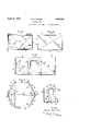
. The invention is illustrated in the accompanying drawings in which Fig. 1 is a plan of the body of a square box and i Fig. 2 is a side elevation of the same in its folded condition partly broken away.
Fig. 3 is an underside view of the box shown in Fig. 1, and
Fig. 4 is an underside view of a box showing a modification.
Fig. 5 is an elevation within the box shown in Fig. 1 seen in the direction of the arrow and showing one form of retaining device for holding down the bottom.
Fig. 6 is a plan of a blank, drawn to a smaller scale, made in a single piece, to produce a square box.
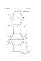
Fig. 7 is a plan of a square box showing a modified retaining device, and Fig. 8 is a section on the line 88 through the box shown in Fig. 7 seen in the direction of the arrow in that figure.
Fig. 9 is a plan of an oblong box and Fig. 10 is an underside view of the same.
Fig. 11 is a side elevation of the box shown in Figs. 9 and 10, in its folded condition, two sides and part of the catch being omitted to show the parts clearly.
Fig. 12 is a plan of a hexagonal box.
Fig. 13 is a section on the line 13-13 of Fig. 12.
Fig. 14 is an underside view ofthe box shown in Fig. 12.
Fig. 15 is'a plan of a blank, made in a single piece to produce a hexagonal box.
As shown in Figs. 1, 2, 3 and 5, the box is formed with four vertical walls 2, 3, 4, 5. To the walls 2 and 5 is hinged, by means of creases, a triangular shaped support 6 which is creased at 7 thereby enabling the parts on each side of said crease to fold towards each other when the sides 2 and 3 are moved towards the sides 5 and 4. This support 6 is indicated by the dotted line in Fig. 1 and is seen fully in Fig. 3.
To the sides 3 and 4 is hinged a bottom 8 which is creased at 9 to allow the same to fold upwards when the box is folded. The bottom 8 is provided in the construction shown in Fig. 1 with flaps 10 on the sides 2 and 5 and flaps .100 on the sides 3 and 4. This bottom, as shown in Figs. 1 to 3, is in fact a separate piece of material and the two flaps 100 are sewn to the vertical sides 3 and 4. The flaps 10 have a tendency to spring outwards against the sides 2 and 5, when the box is erected for use. The friction of these flaps 10 and of the'loose ed es of the bottom 8 a ainst the sides 2 an 5 is 'sufliclent to hold t he bottom imposition upon the support 6 prior to the locking portion herelnafter described. y
The crease 7 always bisects an angle containing a catch, hereinafter described, and the crease 9- bisects-an opposite angle.
The folding su port 6, as shown in Fig. 1, has flaps 11 which vertical sides2 and 5.
The box, the supports and bottom may, however, piece of material, as shown in Fig. 6, providing it is capable of folding in the manner hereinbefore described.
the folding The support 6 may fold either within two lines. 20, are two flaps on the support 6 of the vertical sides, as shown in dotted lines in Fig. 2, or it may fold downwards as shown in full lines and partly broken away. The bottom '8 and its side flaps 10 fold upwards, as shown in 2. The fia s 10 may fold, as shown in 1 same plane as the two portions of the folded bottom 8.
The support 6, instead of being triangular as shown in Fig. 3, may have a portion of the triangle cut away and may thus be.
- 2 and 5.
rendered L shaped, as shown in Fig. 4, other wise the box is the same as that shown in ig. 5 shows one method of constructing the retainin device which, as shown, consists of a str p of cardboard 12 which is-se'wn at its upper part at 13 to the adjacent sides This strip of cardboard is preferably equal in length to the vertical height of the 'sides,as shown, to strengthen the corner of thebox, and, it is creased along its central vertical line at 14 so that it maXfold with the sides to which it is attached. horizontal crease 15 enables the lower part 16 of the strip 12 to be bent upwardsinto the plpsition shown in Fig. 2, in which position t e on to the support 6. The part 16 is then folded downwardly against the upper surface ofthe bottom 8 and against the flaps 10, as seen clearly in Fig. 5 to lock the said bottom upon its support 6.
In the construction shown in Fig. 7 -one of the vertical Walls 17 of the box is bent inwards to form a vertical flap 18, the parts 17 and 18 being provided with a single crease at the bend toenable the part 18 to be readily moved upon the said crease as upon a hinge. In this modification the bottom 8 is provided with a diagonal crease 9 and flaps 10 as in Fig. 1. The vertical flap 18 is moved against the side 19 of the'box to enable the bottom 8 to be pressed down on to a support 6, similar to that shown in Figs. 1 to 3, after which the vertical flap 18 is moved out into the position shown in Fig. 7 between the two vertical flap 18 are sewn to the two be made from a single v g. 2, into t e,
am against the up r sur- When the box shown in Fig. 7 is filled with goods the vertical flap 18 may move, as indicated by the dotted line, against either of the. flaps 10 and against one of the vertical sides 17 and 19. It is onlty necessary to move the flap 18 against one -o the flaps 10and to move the other flap 1O downwards to allow the bottom 8 to rise as the vertical sides of the box are caused to ap roach each other 'and as the supportfi for t e bottom 8 of the box is. caused to fold either between the vertical sides, as shown in Fig. 2 in dotted lines,
or beneath the vertical sides as shown in full j for the bottom, which flaps are shown secured to the outside of the sides 17 and 19.
- F ig. 6 shows a blank cut from a sheet of cardboard suitable for making the body of a box (excluding the. catch) havingall the characteristics of the box shown in Figs. 1,- 2 and 3, similar parts being indicated by similar numerals in all these views. The fla 21 is connected to the side 2 by a crease 22. lhe sides 2, 3, 4 and- 5 are connected b creases 23. The bottom8 is connected to 26, 26-. The triangular part 6, which forms the support for the bottom 8 is connected by a crease'27 to the side 2. The flap 28 is connected to the part 6 by the crease 29. I
To construct the box the four sides are folded on the creases 23 into a square and the flap 21 is secured to the vertical edge of the side 5 in the position indicated by the dotted e side 4 by a crease 24. The flap is connected to the bottom 8 by a crease 25. The two flaps 10 are connected to the bottom 8 by creases lines. The flap 100 is then secured to the ad- 16 forming the retaining device sewn in the angle formed by the sides 2 and 5, as shown in Fig. 5.
In the oblong box shown in Figs. 9 to 11 similar parts are indicated b similar numbers to those employed in Figs. 1 to 3. In this box the crease 9 bisects the angle between the sides 3 and 4 but does not enter the oppo-- site angle inwbich the retaining device 12, 16 is fixed. The crease 7 bisects the angle between the sides 2 and 5 and the support 6 passes diagonally across the box as seen in Fig. 10 and as shown by adotted line in Fi 9. The two parts of the bottom 8 on each si e of the crease 9 fold closely together and the two parts of the support 6 on each side of the crease 7 likewise fold closely together. One of the flaps 10 is folded intermediate of its ends, one portion being vertical and one horizontalas seen clearly in Fig. 11. The other flap 10, that seen on the left hand side of the bottom 8 in Fig. 11, is in the same plane asthat side of the bottom to which it is attached. Part of the retaining device 16 is shown 10 raised in Fig. 11 to allow the bottom 8 and support 6 to fold.
The hexagonal box shown in Figs. 12 to 14 is made from the blank shown in Fig. 15. The vertical sides 29 and 32 are connected by 15 creases directly to opposite sides of the botconnected by creases to the sides and 31 and the two parts of the other support 6 are connected by creases to the sides 33 and 34. The four parts forming the two supports are all marked 6 in Fig. 15. Two of the, parts 6 in this figure carry flaps 35 which are sewn to the two other parts 6 as seen in Fig. 12 where the bottom 8 is broken away to show one connection.
The flaps 10, which fit up against the and 34 are shown as connected by vertical strips 36 which are shown sewn at 37 to two adjoining edges in Fig. 13. Each strip 36 has a vertical crease 38 to allow the sides 30 and 31 to move towards each other.
The folding catches 12, 16 are the same construction as shown in Figs. 1 to 5 and bear by their lower edges upon the upper -surface of the bottom 8 whenthe box is in open position as shown in Fi 13.
What I claim as my invention is 1. A folding box-having in combination vertical sides'adapted to fold towards each other, a bottom connected by creases to two vertical sides, a crease in the bottom bisecting the angle between the sides-to which the bottom is' connected, a' support for the bottom connected by creases to two other vertical sides, a crease in the said support bisectingv the anglebetween the sides towhich the support is connected, a foldingretaining device in the form of a strip fixed in the angle towards each other, the lower edge of the folding retaining device pressing against the upper surface of the bottom when the box is in open position and the .retaining devicg folding to allow the box-to be collapse 2. A folding box having a folding bottom support, a folding bottom, a retainin member placed in the angle between the s1des by which the folding bottom support is carried and acting against the upper surface of the bottom to hold this latter securely against its folding support, and a horizontal fold in the retaining member whereby the portion of the retaining member below said fold which presses against the upper surface of the bottom when the box is in open position may be folded back on itself to allow the box to be collapsed.
3. A folding box havin in combination vertical sides adapted to old towards each other, a folding bottom connected by creases to two vertical sides, afolding support for the bottom connected by creases to two. other vertical sides, a "folding retaining device having a single vertical crease fixed in the angle between the sides by which the support is carried, a horizontal crease in said retaining device, the said retaining device pressing by its lower edge upon the upper surface of the folding bottom when the box is in o 11 position and being folded back on itsel to allow the box to be-collapsed.
4. A folding box having in combination vertical sides adapted to fold towards each other, afolding bottom connected by creases totwo vertical sides, a folding support for the bottom connected by. creases to two other vertical sides, a folding retainin device having a single vertical crease fixe with itscrease in contact with the angle between the sides by which the support is carried, the said retaining device pressing by its lower edge upon the upper surface of the folding bot-.
tom when the box is in open position and being folded back on itself to allow the box to be collapsed.
In witness whereof l have hereunto set my *Ill hand.
between the sides by which the support is I carried and a vertical crease in said strip, in
- contact with said angle, to allow the sides of. v the box on each side of said crease to fold
Applications Claiming Priority (1)
| Application Number | Priority Date | Filing Date | Title |
|---|---|---|---|
| GB1855045X | 1929-07-06 |
Publications (1)
| Publication Number | Publication Date |
|---|---|
| US1855045A true US1855045A (en) | 1932-04-19 |
Family
ID=10892062
Family Applications (1)
| Application Number | Title | Priority Date | Filing Date |
|---|---|---|---|
| US447543A Expired - Lifetime US1855045A (en) | 1929-07-06 | 1930-04-26 | Folding box |
Country Status (1)
| Country | Link |
|---|---|
| US (1) | US1855045A (en) |
Cited By (10)
| Publication number | Priority date | Publication date | Assignee | Title |
|---|---|---|---|---|
| US2549682A (en) * | 1946-08-15 | 1951-04-17 | Alice J Grossniklaus | Foldable box |
| US3377015A (en) * | 1966-03-22 | 1968-04-09 | Moreno Oscar | Six-sided foldable box construction |
| US20050224563A1 (en) * | 2004-04-13 | 2005-10-13 | Turvey Robert R | Collapsible storage device and method of making the same |
| US20060138203A1 (en) * | 2004-04-13 | 2006-06-29 | Turvey Robert R | Container and blank for making the same |
| US20070241174A1 (en) * | 2004-04-13 | 2007-10-18 | Turvey Robert R | Collapsible storage device |
| US20070241173A1 (en) * | 2004-04-13 | 2007-10-18 | Turvey Robert R | Collapsible storage device |
| US20070246519A1 (en) * | 2004-04-13 | 2007-10-25 | Turvey Robert R | Collapsible storage device |
| US20080000901A1 (en) * | 2004-04-13 | 2008-01-03 | Turvey Robert R | Collapsible storage device |
| US20080035717A1 (en) * | 2004-04-13 | 2008-02-14 | Turvey Robert R | Collapsible storage device |
| US20120228370A1 (en) * | 2008-05-29 | 2012-09-13 | Nestec S.A. | Folded box blank |
-
1930
- 1930-04-26 US US447543A patent/US1855045A/en not_active Expired - Lifetime
Cited By (17)
| Publication number | Priority date | Publication date | Assignee | Title |
|---|---|---|---|---|
| US2549682A (en) * | 1946-08-15 | 1951-04-17 | Alice J Grossniklaus | Foldable box |
| US3377015A (en) * | 1966-03-22 | 1968-04-09 | Moreno Oscar | Six-sided foldable box construction |
| US20050224563A1 (en) * | 2004-04-13 | 2005-10-13 | Turvey Robert R | Collapsible storage device and method of making the same |
| US20060138203A1 (en) * | 2004-04-13 | 2006-06-29 | Turvey Robert R | Container and blank for making the same |
| US20070241174A1 (en) * | 2004-04-13 | 2007-10-18 | Turvey Robert R | Collapsible storage device |
| US20070241173A1 (en) * | 2004-04-13 | 2007-10-18 | Turvey Robert R | Collapsible storage device |
| US20070246519A1 (en) * | 2004-04-13 | 2007-10-25 | Turvey Robert R | Collapsible storage device |
| US20080000901A1 (en) * | 2004-04-13 | 2008-01-03 | Turvey Robert R | Collapsible storage device |
| US20080035717A1 (en) * | 2004-04-13 | 2008-02-14 | Turvey Robert R | Collapsible storage device |
| US7631799B2 (en) | 2004-04-13 | 2009-12-15 | S.C. Johnson Home Storage, Inc. | Container and blank for making the same |
| US7699212B2 (en) | 2004-04-13 | 2010-04-20 | S.C. Johnson Home Storage, Inc. | Collapsible storage device and method of making the same |
| US7854370B2 (en) | 2004-04-13 | 2010-12-21 | S.C. Johnson Home Storage, Inc. | Collapsible storage device |
| US8033411B2 (en) | 2004-04-13 | 2011-10-11 | S.C. Johnson Home Storage, Inc. | Collapsible storage device |
| US8066136B2 (en) | 2004-04-13 | 2011-11-29 | S.C. Johnson Home Storage, Inc. | Collapsible storage device |
| US8146763B2 (en) | 2004-04-13 | 2012-04-03 | S.C. Johnson Home Storage, Inc. | Collapsible storage device |
| US8146773B2 (en) | 2004-04-13 | 2012-04-03 | S.C. Johnson & Son, Inc. | Collapsible storage device |
| US20120228370A1 (en) * | 2008-05-29 | 2012-09-13 | Nestec S.A. | Folded box blank |
Similar Documents
| Publication | Publication Date | Title |
|---|---|---|
| US2345716A (en) | Hollow walled carton | |
| US1855045A (en) | Folding box | |
| US1699008A (en) | Box | |
| US2304373A (en) | Package | |
| US2077173A (en) | Container | |
| US2374006A (en) | Carton | |
| US2926831A (en) | Infold carton with corner bracing strut | |
| US2807403A (en) | Triangular carton | |
| US2334985A (en) | Paper tray | |
| US1940292A (en) | Carton | |
| US1700758A (en) | Collapsible box and blank therefor | |
| US2680557A (en) | Frozen confection sandwich container | |
| US2678766A (en) | Box or carton | |
| US1729014A (en) | Collapsible display | |
| US1947168A (en) | Display stand | |
| US2893622A (en) | Display package | |
| US1497536A (en) | Box | |
| US2459727A (en) | Bulk ice-cream container | |
| US1876200A (en) | Carton | |
| US2210566A (en) | Display receptacle | |
| US2389580A (en) | Knockdown box | |
| US2036542A (en) | Folding box | |
| US1471478A (en) | Folding paper box | |
| US1301201A (en) | Display-box. | |
| US991052A (en) | Folding box. |