US2000221A - Power wrench for well tubing and rods - Google Patents
Power wrench for well tubing and rods Download PDFInfo
- Publication number
- US2000221A US2000221A US679921A US67992133A US2000221A US 2000221 A US2000221 A US 2000221A US 679921 A US679921 A US 679921A US 67992133 A US67992133 A US 67992133A US 2000221 A US2000221 A US 2000221A
- Authority
- US
- United States
- Prior art keywords
- chuck
- head
- arm
- carrier
- tubing
- Prior art date
- Legal status (The legal status is an assumption and is not a legal conclusion. Google has not performed a legal analysis and makes no representation as to the accuracy of the status listed.)
- Expired - Lifetime
Links
Images

Classifications
-
- E—FIXED CONSTRUCTIONS
- E21—EARTH DRILLING; MINING
- E21B—EARTH DRILLING, e.g. DEEP DRILLING; OBTAINING OIL, GAS, WATER, SOLUBLE OR MELTABLE MATERIALS OR A SLURRY OF MINERALS FROM WELLS
- E21B19/00—Handling rods, casings, tubes or the like outside the borehole, e.g. in the derrick; Apparatus for feeding the rods or cables
- E21B19/16—Connecting or disconnecting pipe couplings or joints
- E21B19/167—Connecting or disconnecting pipe couplings or joints using a wrench adapted to engage a non circular section of pipe, e.g. a section with flats or splines
-
- Y—GENERAL TAGGING OF NEW TECHNOLOGICAL DEVELOPMENTS; GENERAL TAGGING OF CROSS-SECTIONAL TECHNOLOGIES SPANNING OVER SEVERAL SECTIONS OF THE IPC; TECHNICAL SUBJECTS COVERED BY FORMER USPC CROSS-REFERENCE ART COLLECTIONS [XRACs] AND DIGESTS
- Y10—TECHNICAL SUBJECTS COVERED BY FORMER USPC
- Y10T—TECHNICAL SUBJECTS COVERED BY FORMER US CLASSIFICATION
- Y10T29/00—Metal working
- Y10T29/53—Means to assemble or disassemble
- Y10T29/53687—Means to assemble or disassemble by rotation of work part
Definitions
- the present invention relates to power operated wrenches especially adapted for unscrewing and screwing up thev joints of well tubing and sucker rod springs.
- the principal object of the invention is .to' provide an apparatus of the described type which' is easy and quick to use, and which can be operated by one man, thus saving both time and labor in the customarily tedious operation of pulling and replacing the tubing and sucker rod strings in deep wells.
- Other objects of the invention are to provide readily interchangeable jaws of chucks for gripping different sizes of pipes and rods; to provide a movable chuck carrying head which can be applied to and removed from the tubing without moving the main body vand motor of the machine; and to provide for the adequate and rigid support of said main
- the invention is herein illustrated andvdescribed as embodied in a machine for rotating the tubing and sucker rod sections of a deep well for the purpose of screwing up and unscrewing the joints thereof.
- Fig. 1 is a vertical part sectional view of preferred embodiment of the invention as applied to ⁇ the casing head and tubing string of a well.
- Fig. 2 is a horizontal section of the head, ⁇
- Fig. 3 is a transverse sectional detail of the chuck, taken on the line 3 of Fig. 2 and enlarged.
- Fig. 4 is a part sectional elevation of the head as applied to a sucker rod string.
- Fig. 5 is a horizontal section on the line 5-5 of Fig. 4.
- Fig. 6 is a perspective view of the complete machine.
- Fig. 7 is a side elevation of a portion of the machine, showing the clutch operating lever.
- the machine comprises 'a main frame of carriage I I provided with wheels I2 adapted to rest movably upon the derrick floor, and a swinging head I3 which carries the jaws for gripping the well tubing or sucker rods.
- Any suitable means may be usedv for anchoring the carriage II, either to the casing head or to the derrick oor.
- I have shown a 5 forked clamp I4 extending from one end of the carriage and adapted toembrace the projecting head of the well casing Isaid clamp having set screws I 3 by which' itis rigidly secured to said casing.
- an eg- 10 tension I1 which may be secured to the floor by a bolt.
- the carriage vII supports an electric motor lI3 and a gear and clutch housing I9.
- the hori ⁇ zontal motor shaft Fig; l enters the rear end 15 of said housing andhas a pinion 2l fixed upon it, which meshes with an idler gear 22.
- a bevel pinion 23, secured to said idler drives a bevel gear 24 secured upon a vertical shaft 25.
- a pinion 26 on said shaft 25 drives a larger gear 21 20 upon a second vertical shaft 28.
- a smaller gear 23 is also secured upon said sha ⁇ ft 28.
- the gears 21 and 29 mesh respectively with gears 30 and 3
- the gear' 30 is secured td one member 33 of a friction cone clutch, th' other member 34 thereof being slidable upon the shaft 32, but prevented-from rotating thereon by a transverse pin or key 35.
- the lower face of 30 ,the sliding clutch member 34 is provided with dogs or jaws 36, which engage similar jaws 31 on the gear 3
- the clutch member ⁇ 34 isshifted by a rod 38, secured to the transverse key 35 and extending downwardly through the center of the shaft 32.
- a thrust collar 33 connected with an arm 40 secured upon a rock 45 shaft 4I, which extends to the side of the housing and is provided with a second arm 42, Fig. 7, connected by a link 43 with an operating lever 44.
- the driven shaft 32 may be started and stopped, and operated at 50 two different speeds. Reversal of said shaft is accomplished by reversing the driving motor I3.
- 'I'he shaft 32 extends upwardly through the top of the housing I9, and drives the Wrench jaw mounted Within the head I3, as shown in Fig. 1.
- a tubular arm 45 extends upwardly vfrom said housing, and is connected therewith by a hinge joint 46. Within said arm is an extension. 41 oi' the shaft 32, having two universal joints and a slip joint 48. The arm 45 is also made with a slip joint 50, its two telescoping portions being prevented from turning upon each other by splines 5I. l'Ihe heaii I3 is secured to the upper portion of the arm 45 and itsweight is approximately balanced by a helical spring 52.
- the outer end portion of said head I3 carries a rotatable chuck carrier 58, Figs. 1 and 2, in the form of a partial ring having a center aperture 51 and a radial slot 58 leading outwardly therefrom to its periphery, said aperture and slot being wide enough to slip over or around the largest tubing for which the machine is designed.
- the chuck carrier 56 is journaled in the head I3 by means of circular grooves53 in its upper and lower faces which engage corresponding iianges formed upon the inside of the head.
- the carrier 56 is provided with peripheral gear teeth, which mesh with the endmost 'idler pinions 55, said idlers being spaced apart suillciently to span the gap 56 in the carrier gear, so that one idler is always in mesh therewith.
- the outer end of the head is providedA with a swinging gate or guard 60, which may be opened to permit it to pass around the tubing. It will thus be seen that the chuck carrier 56, which is rotated by the extension shaft 41, is flrmly journaled in the head I3, and'positively driven by the gears 54 and 55, even though it is not a complete circle, but has a gap in it to allow it to be slipped over the tubing string from the side.
- the upper face of the carrier 56 is recessed to receive a chuck 6
- the upper plate of the head I3 is apertured to permit said chuck to Ybe removed and replaced readily.
- Several different chucks are provided, all having the same exterior dimensions to make them interchangeable in the' carrier 56.
- Each chuck is provided withv a radial slot 63 aligned with the yslot 58 in the carrier. 'I'he center por-f tions of the chucks are formed to fit and grip whatever object is to be rotated. In Figs.
- a chuck V adapted for gripping the well tubing 64, said chuck having a pair of toothed wedge jaws 65 slidably mounted upon undercut inclined guides 66, Fig. 3, and pressedinwardly by springs 61, thus forming an automatic pipe gripping chuck.
- the chuck 6I is reversible, i. e. it can be placed either side up in the carrier 56 according to the direction of gripping desired.
- Another form of chuck, for gripping squared sucker rods, is shown at 6I in Fig. 5, having 'merely a rectangular central aperture 68 of suitable size to grip rod 89.
- the tubing 64 is pulled up by the usual elevator and tackle, until a joint 10, Fig. 1, rises above the casing head.
- Tapered slips 1I are employed to hold the tubing string by gripping its second section at the casing head, in the usual manner.
- the carriage II is then brought up, and anchored to the floor or casing-head, or both, as circumstances may require.
- the swinging arm 45, carryingthe head I3 with the proper chuck 6I therein, is then moved upwardly and said head and chuck are slipped the squared portion of the sucker wrench 12 of common form is used to hold the lower rod section.
- This wrench can be held in any suitable manner, as for example by a chain 'I3 attached to the head I3.
- the machine can be operated quickly and easily by one man.
- the carriage II upon which the heavy parts are mounted, need not be moved until the y entire pulling job is iinished, the head I3 being merely swung into and out of operative position at each joint oi' tubing.
- the slip joints 49 and 50 in the extension shaft and arm enable the head torise or descend with the rotating tubing section.
- the chuck is engaged with and disengaged fromdzhe tubing merely by the act of moving the head into and out of operative position, the only .gate beingthe sinple swinging guard 60 which can be opened and shut quickly and easily.
- By providing two spaced pinions 55 for driving the slotted chuck carrier 56 assuring the meshing of at least one pinion therewith at all times. I eliminate the necessity'for a complicated and troublesome gate to complete the peripheral gear of said carrier.
- a power wrench comprising a frame; a hollow arm connected therewith for movement into and out of operating position; a head mounted directly upon and wholly supported by said arm; a work engaging chuck rotatably mounted in said head; a motor mounted on said frame and a shaft journaled within said arm for transmitting power from said motor to said chuck.
- a power wrench comprising a frame; a hollow arm movably connected therewith; means for anchoring said frame; a work engaging chuck rotatably mountedon the upper end of said arm and wholly-supported thereby; a shaft journaled .within said arm for rotating said chuck; and means mounted upon said frame for driving said shaft.
- vA power wrench comprising a frame; a hollow arm connected therewith for movement into and out of operating position; a head carried by the upper ends of said arm and wholly supported thereby; a work engaging chuck rotatably mounted in said head; variable speed gearing mounted on said frame; a shaft journaled within said arm for transmitting power from said gearing to said chuck; and power means for driving said gearing.
- a power wrench for well tubing comprising a carriage adapted to rest upon the derrick iioor in proximity to the casing head; means for anchoring said carriage; a swinging arm rising from said carriage, said .arm being movable toward and away from the well tubing; a rotatable chuck Ain proximity to the casing head; means for an choringsaid carriage; a movable arm secured to and rising from said carriage; a rotatable chuck carried by said arm, said arm being mounted for movement upon said carriage to carry said chuck into and out of engagement with the well tubing. and said arm being extensible and retractible to enable said chuck to move up and down with said tubing; power means mounted on said carriage; and an articulated shaft journaled in said arm connecting said power means with said chuck.
- a power wrench for well tubing comprising a carriage adapted to rest upon the derrick iioor in proximity to the casing head; means for anchoring said carriage; a tubular telescoping. nonrotatable arm having its lower end pivoted to said carriage for movement toward and away from the well tubing; a rotatable chuck carried by the upper end of said arm for engagement with said tubing; power means mounted on said carriage; and an articulated shaft journaled in said arm connecting said power means with said chuck.
- a power wrench comprising a frame; power means mounted thereon; a jointed movable arm extending therefrom; a head carried by said arm, said head having a slot therein; a rotatable chuck in said head, said chuck having a central work engaging aperture and a slot extending outwardly therefrom to its periphery, the slot in said chuck corresponding with the slot in said head at one point in the rotation of said chuck; a partial gear carried by said chuck, said gear being interrupted at said slot; a pair of pinions in said head meshing with said gear and spaced apart to bridge said slot; a driving gear meshing with said pinions; and a shaftjournaled in said arm for connecting said power means and said driving gear.
- a power wrench comprising a frame; an upstanding extensible arm connected therewith; a head mounted directly upon the upper end oi.' said arm and wholly supported thereby; a work engaging chuck rotatably mounted in said head; a spring associated with said arm for partially supporting the weight of said head and chuck; and means for rotating said chuck.
- a power wrench comprising a frame; an upstanding arm pivotally connected therewith for swinging movement in a vertical plane into and out of operative position; a work engaging chuck rotatably carried by said arm; and means for rotating said chuck.
- a power wrench comprising a trame; an extensible up'standing arm pivotally connected therewith for swinging movement in a vertical plane; a rotatable work engaging chuck carried by said arm; an articulated extensible shaft carried by saidarm for rotating said chuck; and means mounted upon said frame for driving said shaft.
- a power wrench for pipes, rods and the like comprising a rotatable chuck carrier having a central aperture and a slotextending outwardly therefrom to its periphery; a chuck removably mounted in said carrier and provided with a slot aligned with the slot in said carrier; jaws mounted in said chuck for gripping the work in one rotative direction, said chuck being bodily invertible in said carrier to enable it to grip and turn the work in either direction; and means for rotating said carrier in either direction.
- a power wrench for pipes, rods and the like comprising a rotatable chuck carrier having a recessed upper face, a central aperture, and a slot extending outwardly therefrom to its periphery; a chuck removably seated in the recess of said carrier, said chuck having a slot aligned with the carrier slot; interengaging means upon said carrier and said chuck to prevent relative rotation; jaws mounted in said chuck for gripping the work in one rotative direction, said chuck being bodily invertible in said carrier to enable it to grip and turn the work in either direction; and means for rotating said carrier in either direction.
- a power wrench for pipes, rods and the like comprising a head having spaced horizontal plates; a chuck carrier between said plates, the adjacent faces of 'said carrier and said plates being provided with annular interengaglng guide means whereby said carrier is rotatably mounted in said head; a chuck mounted upon said carrier, said chuck, said carrier, and said head being provided with aligned central work receiving apertures and slots leading outwardly therefrom; peripheral gear teeth formed upon said carrier, said gear being interrupted at said slot; a pair of pinions mounted in said head and engaging the carrier gear, said pinions being spaced apart to bridge said slot, whereby one pinion is always in engagement with said gear; and power means ⁇ for rotating said pinions.
Description
May 7, 1935. C. w. DAWSON 2,000,221
POWER WRENCH FOR WELL TUBING AND RODS Filed July ll, 1935 2 Sheets-Sheet l BY 73Mfv ATTORNEYS.
May 7, 1935. c. w. DAWSON POWER WRENCH FOR WELL TUBING AND RODS Filed July 11, 1933 2 Sheets-Sheet 2 INVENTOR.,
BY am; f @Ww 73mg@ 73mm? ATTORNEYS.
Patented May 7, 1935 f ulvl'rrbA STATES POWER WRENCH FOB WELL TUBING Y AND RODS l carlton w. Damn, raft, cam. Ansmann .my 11, 1933, sei-15a No. 679,921
13 Claims.
`The present invention relates to power operated wrenches especially adapted for unscrewing and screwing up thev joints of well tubing and sucker rod springs.
The principal object of the invention is .to' provide an apparatus of the described type which' is easy and quick to use, and which can be operated by one man, thus saving both time and labor in the customarily tedious operation of pulling and replacing the tubing and sucker rod strings in deep wells. Other objects of the invention are to provide readily interchangeable jaws of chucks for gripping different sizes of pipes and rods; to provide a movable chuck carrying head which can be applied to and removed from the tubing without moving the main body vand motor of the machine; and to provide for the adequate and rigid support of said main The invention is herein illustrated andvdescribed as embodied in a machine for rotating the tubing and sucker rod sections of a deep well for the purpose of screwing up and unscrewing the joints thereof. It will be apparent, however, that theL machine, if constructed of suit-- able size, may be used for rotating well casing sections, or for any other purpose for which a power wrench is useful. It should be understood, moreover, that the form, construction and arrangement of the several parts may be varied, within the limits of the claims hereto appended, without departing from the spirit of the4 invention as set forth therein.
Reference will be made to the accompanying drawings, wherein:
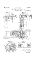
Fig. 1 is a vertical part sectional view of preferred embodiment of the invention as applied to` the casing head and tubing string of a well.
Fig. 2 is a horizontal section of the head,`
taken on the line 2-2 of Fig. 1.
Fig. 3 is a transverse sectional detail of the chuck, taken on the line 3 of Fig. 2 and enlarged.
Fig. 4 is a part sectional elevation of the head as applied to a sucker rod string.
Fig. 5 is a horizontal section on the line 5-5 of Fig. 4.
Fig. 6 is a perspective view of the complete machine.
Fig. 7 is a side elevation of a portion of the machine, showing the clutch operating lever.
In its preferred form, the machine comprises 'a main frame of carriage I I provided with wheels I2 adapted to rest movably upon the derrick floor, and a swinging head I3 which carries the jaws for gripping the well tubing or sucker rods. Any suitable means may be usedv for anchoring the carriage II, either to the casing head or to the derrick oor. For example, I have shown a 5 forked clamp I4 extending from one end of the carriage and adapted toembrace the projecting head of the well casing Isaid clamp having set screws I 3 by which' itis rigidly secured to said casing. At the rear end of the machine is an eg- 10 tension I1 which may be secured to the floor by a bolt. f
1 The carriage vII supports an electric motor lI3 and a gear and clutch housing I9. The hori` zontal motor shaft Fig; l, enters the rear end 15 of said housing andhas a pinion 2l fixed upon it, which meshes with an idler gear 22. A bevel pinion 23, secured to said idler, drives a bevel gear 24 secured upon a vertical shaft 25. A pinion 26 on said shaft 25 drives a larger gear 21 20 upon a second vertical shaft 28. A smaller gear 23 is also secured upon said sha`ft 28. The gears 21 and 29 mesh respectively with gears 30 and 3|, both of which are independently rotatable upon a third vertical shaft 32, which is the driven shaft of the gear set. The gear' 30 is secured td one member 33 of a friction cone clutch, th' other member 34 thereof being slidable upon the shaft 32, but prevented-from rotating thereon by a transverse pin or key 35. The lower face of 30 ,the sliding clutch member 34 is provided with dogs or jaws 36, which engage similar jaws 31 on the gear 3|. Thus when the clutch member 34 is moved downwardly, the gear 3| is clutched to the shaft 32, and said shaft is driven, at a 35 comparatively low speed,vby the gears V2!) and 3l. When said clutch member is moved upwardly, the gear 30 is clutched to the shaft 32, which is thendriven at a higher s peed by the gears 21 and 30.
The clutch member` 34 isshifted by a rod 38, secured to the transverse key 35 and extending downwardly through the center of the shaft 32.
At the bottom of'said rod is a thrust collar 33 connected with an arm 40 secured upon a rock 45 shaft 4I, which extends to the side of the housing and is provided with a second arm 42, Fig. 7, connected by a link 43 with an operating lever 44. Thus by moving said lever, the driven shaft 32 may be started and stopped, and operated at 50 two different speeds. Reversal of said shaft is accomplished by reversing the driving motor I3. 'I'he shaft 32 extends upwardly through the top of the housing I9, and drives the Wrench jaw mounted Within the head I3, as shown in Fig. 1.
` A tubular arm 45 extends upwardly vfrom said housing, and is connected therewith by a hinge joint 46. Within said arm is an extension. 41 oi' the shaft 32, having two universal joints and a slip joint 48. The arm 45 is also made with a slip joint 50, its two telescoping portions being prevented from turning upon each other by splines 5I. l'Ihe heaii I3 is secured to the upper portion of the arm 45 and itsweight is approximately balanced by a helical spring 52.
'Ihe upper end 53 of theshaft extension 41 is journaled in the head I3, and has a gear 54 secured upon it, which drives twotrains of idler pin-- ions 55, Fig. 2. The outer end portion of said head I3 carries a rotatable chuck carrier 58, Figs. 1 and 2, in the form of a partial ring having a center aperture 51 and a radial slot 58 leading outwardly therefrom to its periphery, said aperture and slot being wide enough to slip over or around the largest tubing for which the machine is designed. The chuck carrier 56 is journaled in the head I3 by means of circular grooves53 in its upper and lower faces which engage corresponding iianges formed upon the inside of the head. The carrier 56 is provided with peripheral gear teeth, which mesh with the endmost 'idler pinions 55, said idlers being spaced apart suillciently to span the gap 56 in the carrier gear, so that one idler is always in mesh therewith. The outer end of the head is providedA with a swinging gate or guard 60, which may be opened to permit it to pass around the tubing. It will thus be seen that the chuck carrier 56, which is rotated by the extension shaft 41, is flrmly journaled in the head I3, and'positively driven by the gears 54 and 55, even though it is not a complete circle, but has a gap in it to allow it to be slipped over the tubing string from the side.
The upper face of the carrier 56 is recessed to receive a chuck 6|, which is prevented from rotating in said carrier by splines 62, Figs. 2 and 3. The upper plate of the head I3 is apertured to permit said chuck to Ybe removed and replaced readily. Several different chucks are provided, all having the same exterior dimensions to make them interchangeable in the' carrier 56. Each chuck is provided withv a radial slot 63 aligned with the yslot 58 in the carrier. 'I'he center por-f tions of the chucks are formed to fit and grip whatever object is to be rotated. In Figs. 2 and 3 is shown a chuck Vadapted for gripping the well tubing 64, said chuck having a pair of toothed wedge jaws 65 slidably mounted upon undercut inclined guides 66, Fig. 3, and pressedinwardly by springs 61, thus forming an automatic pipe gripping chuck. The chuck 6I is reversible, i. e. it can be placed either side up in the carrier 56 according to the direction of gripping desired. Another form of chuck, for gripping squared sucker rods, is shown at 6I in Fig. 5, having 'merely a rectangular central aperture 68 of suitable size to grip rod 89.
In operating the device, for instance in pulling the tubing string from a well, the tubing 64 is pulled up by the usual elevator and tackle, until a joint 10, Fig. 1, rises above the casing head. Tapered slips 1I are employed to hold the tubing string by gripping its second section at the casing head, in the usual manner. The carriage II is then brought up, and anchored to the floor or casing-head, or both, as circumstances may require. The swinging arm 45, carryingthe head I3 with the proper chuck 6I therein, is then moved upwardly and said head and chuck are slipped the squared portion of the sucker wrench 12 of common form is used to hold the lower rod section. This wrench can be held in any suitable manner, as for example by a chain 'I3 attached to the head I3.
It will be seen from the foregoing that the machine can be operated quickly and easily by one man. The carriage II, upon which the heavy parts are mounted, need not be moved until the y entire pulling job is iinished, the head I3 being merely swung into and out of operative position at each joint oi' tubing. The slip joints 49 and 50 in the extension shaft and arm enable the head torise or descend with the rotating tubing section. The chuck is engaged with and disengaged fromdzhe tubing merely by the act of moving the head into and out of operative position, the only .gate beingthe sinple swinging guard 60 which can be opened and shut quickly and easily. By providing two spaced pinions 55 for driving the slotted chuck carrier 56, assuring the meshing of at least one pinion therewith at all times. I eliminate the necessity'for a complicated and troublesome gate to complete the peripheral gear of said carrier.
I claim:-
l. A power wrench comprising a frame; a hollow arm connected therewith for movement into and out of operating position; a head mounted directly upon and wholly supported by said arm; a work engaging chuck rotatably mounted in said head; a motor mounted on said frame and a shaft journaled within said arm for transmitting power from said motor to said chuck.
2. A power wrench comprising a frame; a hollow arm movably connected therewith; means for anchoring said frame; a work engaging chuck rotatably mountedon the upper end of said arm and wholly-supported thereby; a shaft journaled .within said arm for rotating said chuck; and means mounted upon said frame for driving said shaft.
3. vA power wrench comprising a frame; a hollow arm connected therewith for movement into and out of operating position; a head carried by the upper ends of said arm and wholly supported thereby; a work engaging chuck rotatably mounted in said head; variable speed gearing mounted on said frame; a shaft journaled within said arm for transmitting power from said gearing to said chuck; and power means for driving said gearing.
4. A power wrench for well tubing comprising a carriage adapted to rest upon the derrick iioor in proximity to the casing head; means for anchoring said carriage; a swinging arm rising from said carriage, said .arm being movable toward and away from the well tubing; a rotatable chuck Ain proximity to the casing head; means for an choringsaid carriage; a movable arm secured to and rising from said carriage; a rotatable chuck carried by said arm, said arm being mounted for movement upon said carriage to carry said chuck into and out of engagement with the well tubing. and said arm being extensible and retractible to enable said chuck to move up and down with said tubing; power means mounted on said carriage; and an articulated shaft journaled in said arm connecting said power means with said chuck.
6. A power wrench for well tubing comprising a carriage adapted to rest upon the derrick iioor in proximity to the casing head; means for anchoring said carriage; a tubular telescoping. nonrotatable arm having its lower end pivoted to said carriage for movement toward and away from the well tubing; a rotatable chuck carried by the upper end of said arm for engagement with said tubing; power means mounted on said carriage; and an articulated shaft journaled in said arm connecting said power means with said chuck.
7. A power wrench comprising a frame; power means mounted thereon; a jointed movable arm extending therefrom; a head carried by said arm, said head having a slot therein; a rotatable chuck in said head, said chuck having a central work engaging aperture and a slot extending outwardly therefrom to its periphery, the slot in said chuck corresponding with the slot in said head at one point in the rotation of said chuck; a partial gear carried by said chuck, said gear being interrupted at said slot; a pair of pinions in said head meshing with said gear and spaced apart to bridge said slot; a driving gear meshing with said pinions; and a shaftjournaled in said arm for connecting said power means and said driving gear.
8. A power wrench comprising a frame; an upstanding extensible arm connected therewith; a head mounted directly upon the upper end oi.' said arm and wholly supported thereby; a work engaging chuck rotatably mounted in said head; a spring associated with said arm for partially supporting the weight of said head and chuck; and means for rotating said chuck.
9. A power wrench comprising a frame; an upstanding arm pivotally connected therewith for swinging movement in a vertical plane into and out of operative position; a work engaging chuck rotatably carried by said arm; and means for rotating said chuck.
10. A power wrench comprising a trame; an extensible up'standing arm pivotally connected therewith for swinging movement in a vertical plane; a rotatable work engaging chuck carried by said arm; an articulated extensible shaft carried by saidarm for rotating said chuck; and means mounted upon said frame for driving said shaft.
1l. A power wrench for pipes, rods and the like-comprising a rotatable chuck carrier having a central aperture and a slotextending outwardly therefrom to its periphery; a chuck removably mounted in said carrier and provided with a slot aligned with the slot in said carrier; jaws mounted in said chuck for gripping the work in one rotative direction, said chuck being bodily invertible in said carrier to enable it to grip and turn the work in either direction; and means for rotating said carrier in either direction.
12. A power wrench for pipes, rods and the like comprising a rotatable chuck carrier having a recessed upper face, a central aperture, and a slot extending outwardly therefrom to its periphery; a chuck removably seated in the recess of said carrier, said chuck having a slot aligned with the carrier slot; interengaging means upon said carrier and said chuck to prevent relative rotation; jaws mounted in said chuck for gripping the work in one rotative direction, said chuck being bodily invertible in said carrier to enable it to grip and turn the work in either direction; and means for rotating said carrier in either direction. n
13. A power wrench for pipes, rods and the like comprising a head having spaced horizontal plates; a chuck carrier between said plates, the adjacent faces of 'said carrier and said plates being provided with annular interengaglng guide means whereby said carrier is rotatably mounted in said head; a chuck mounted upon said carrier, said chuck, said carrier, and said head being provided with aligned central work receiving apertures and slots leading outwardly therefrom; peripheral gear teeth formed upon said carrier, said gear being interrupted at said slot; a pair of pinions mounted in said head and engaging the carrier gear, said pinions being spaced apart to bridge said slot, whereby one pinion is always in engagement with said gear; and power means `for rotating said pinions.
Priority Applications (1)
| Application Number | Priority Date | Filing Date | Title |
|---|---|---|---|
| US679921A US2000221A (en) | 1933-07-11 | 1933-07-11 | Power wrench for well tubing and rods |
Applications Claiming Priority (1)
| Application Number | Priority Date | Filing Date | Title |
|---|---|---|---|
| US679921A US2000221A (en) | 1933-07-11 | 1933-07-11 | Power wrench for well tubing and rods |
Publications (1)
| Publication Number | Publication Date |
|---|---|
| US2000221A true US2000221A (en) | 1935-05-07 |
Family
ID=24728938
Family Applications (1)
| Application Number | Title | Priority Date | Filing Date |
|---|---|---|---|
| US679921A Expired - Lifetime US2000221A (en) | 1933-07-11 | 1933-07-11 | Power wrench for well tubing and rods |
Country Status (1)
| Country | Link |
|---|---|
| US (1) | US2000221A (en) |
Cited By (28)
| Publication number | Priority date | Publication date | Assignee | Title |
|---|---|---|---|---|
| US2453369A (en) * | 1945-05-15 | 1948-11-09 | Donovan B Grable | Pipe tongs |
| US2518398A (en) * | 1946-08-22 | 1950-08-08 | Standard Oil Dev Co | Apparatus for spinning pipe |
| US2550045A (en) * | 1945-12-22 | 1951-04-24 | Hetre John P De | Power-driven pipe tongs |
| US2556536A (en) * | 1946-12-17 | 1951-06-12 | Hillman Kelley | Power-driven, gear-operated, member-holding wrench |
| US2570080A (en) * | 1948-05-01 | 1951-10-02 | Standard Oil Dev Co | Device for gripping pipes |
| US2618468A (en) * | 1947-12-30 | 1952-11-18 | Byron Jackson Co | Power tong |
| US2623734A (en) * | 1947-04-15 | 1952-12-30 | Walter C Sibble | Power-operated pipe wrench |
| US2633333A (en) * | 1948-05-17 | 1953-03-31 | Lynn W Storm | Pipe spinner |
| US2646966A (en) * | 1951-12-11 | 1953-07-28 | Glenn A Lindberg | Power-operated wrench |
| US2657908A (en) * | 1949-09-03 | 1953-11-03 | George E Failing Supply Compan | Breakout table |
| US2668689A (en) * | 1947-11-07 | 1954-02-09 | C & C Tool Corp | Automatic power tongs |
| US2705614A (en) * | 1949-05-07 | 1955-04-05 | Byron Jackson Co | Power operated pipe tongs |
| US2850929A (en) * | 1954-07-06 | 1958-09-09 | Jersey Prod Res Co | Drill pipe spinner |
| US3141362A (en) * | 1960-05-12 | 1964-07-21 | Byron Jackson Inc | Jaw operating structure for a power-operated wrench |
| US3142210A (en) * | 1962-06-22 | 1964-07-28 | Rodgers Hydraulic Inc | Power operated wrench with two-speed drive |
| US3144794A (en) * | 1961-06-26 | 1964-08-18 | Foster James Lewis | Power driven sucker rod wrench |
| US3392609A (en) * | 1966-06-24 | 1968-07-16 | Abegg & Reinhold Co | Well pipe spinning unit |
| US3500708A (en) * | 1967-05-01 | 1970-03-17 | Wilson John H | Automated pipe tongs |
| US3771389A (en) * | 1972-05-19 | 1973-11-13 | Ingersoll Rand Co | Motorized tool assembly for drill rods |
| US4023449A (en) * | 1975-02-18 | 1977-05-17 | Varco International, Inc. | Tool for connecting and disconnecting well pipe |
| US4084429A (en) * | 1976-05-03 | 1978-04-18 | Foster Cathead Corporation | Power tong apparatus |
| WO1982000428A1 (en) * | 1980-07-31 | 1982-02-18 | Varco Int | Well pipe connecting and disconnecting apparatus |
| US4400815A (en) * | 1982-01-26 | 1983-08-23 | Owens-Corning Fiberglas Corporation | Electrode aligning apparatus |
| EP0185605A1 (en) * | 1984-12-04 | 1986-06-25 | Varco International, Inc. | Top drive drilling systems |
| EP0202184A1 (en) * | 1985-04-01 | 1986-11-20 | Varco International, Inc. | Well pipe stabbing and back-up apparatus |
| WO1989003470A1 (en) * | 1987-10-08 | 1989-04-20 | Matti Varis | A gripping and rotating tong device |
| US20130118315A1 (en) * | 2011-11-11 | 2013-05-16 | Target Drilling, Inc. | Drill Pipe Breakout Machine |
| US9945195B2 (en) * | 2012-09-20 | 2018-04-17 | Frank Jost | Method for connecting a drill head to a drill pipe, and device for holding a drill head |
-
1933
- 1933-07-11 US US679921A patent/US2000221A/en not_active Expired - Lifetime
Cited By (31)
| Publication number | Priority date | Publication date | Assignee | Title |
|---|---|---|---|---|
| US2453369A (en) * | 1945-05-15 | 1948-11-09 | Donovan B Grable | Pipe tongs |
| US2550045A (en) * | 1945-12-22 | 1951-04-24 | Hetre John P De | Power-driven pipe tongs |
| US2518398A (en) * | 1946-08-22 | 1950-08-08 | Standard Oil Dev Co | Apparatus for spinning pipe |
| US2556536A (en) * | 1946-12-17 | 1951-06-12 | Hillman Kelley | Power-driven, gear-operated, member-holding wrench |
| US2623734A (en) * | 1947-04-15 | 1952-12-30 | Walter C Sibble | Power-operated pipe wrench |
| US2668689A (en) * | 1947-11-07 | 1954-02-09 | C & C Tool Corp | Automatic power tongs |
| US2618468A (en) * | 1947-12-30 | 1952-11-18 | Byron Jackson Co | Power tong |
| US2570080A (en) * | 1948-05-01 | 1951-10-02 | Standard Oil Dev Co | Device for gripping pipes |
| US2633333A (en) * | 1948-05-17 | 1953-03-31 | Lynn W Storm | Pipe spinner |
| US2705614A (en) * | 1949-05-07 | 1955-04-05 | Byron Jackson Co | Power operated pipe tongs |
| US2657908A (en) * | 1949-09-03 | 1953-11-03 | George E Failing Supply Compan | Breakout table |
| US2646966A (en) * | 1951-12-11 | 1953-07-28 | Glenn A Lindberg | Power-operated wrench |
| US2850929A (en) * | 1954-07-06 | 1958-09-09 | Jersey Prod Res Co | Drill pipe spinner |
| US3141362A (en) * | 1960-05-12 | 1964-07-21 | Byron Jackson Inc | Jaw operating structure for a power-operated wrench |
| US3144794A (en) * | 1961-06-26 | 1964-08-18 | Foster James Lewis | Power driven sucker rod wrench |
| US3142210A (en) * | 1962-06-22 | 1964-07-28 | Rodgers Hydraulic Inc | Power operated wrench with two-speed drive |
| US3392609A (en) * | 1966-06-24 | 1968-07-16 | Abegg & Reinhold Co | Well pipe spinning unit |
| US3500708A (en) * | 1967-05-01 | 1970-03-17 | Wilson John H | Automated pipe tongs |
| US3771389A (en) * | 1972-05-19 | 1973-11-13 | Ingersoll Rand Co | Motorized tool assembly for drill rods |
| US4023449A (en) * | 1975-02-18 | 1977-05-17 | Varco International, Inc. | Tool for connecting and disconnecting well pipe |
| US4084429A (en) * | 1976-05-03 | 1978-04-18 | Foster Cathead Corporation | Power tong apparatus |
| WO1982000428A1 (en) * | 1980-07-31 | 1982-02-18 | Varco Int | Well pipe connecting and disconnecting apparatus |
| US4348920A (en) * | 1980-07-31 | 1982-09-14 | Varco International, Inc. | Well pipe connecting and disconnecting apparatus |
| US4400815A (en) * | 1982-01-26 | 1983-08-23 | Owens-Corning Fiberglas Corporation | Electrode aligning apparatus |
| EP0185605A1 (en) * | 1984-12-04 | 1986-06-25 | Varco International, Inc. | Top drive drilling systems |
| EP0202184A1 (en) * | 1985-04-01 | 1986-11-20 | Varco International, Inc. | Well pipe stabbing and back-up apparatus |
| WO1989003470A1 (en) * | 1987-10-08 | 1989-04-20 | Matti Varis | A gripping and rotating tong device |
| US5048377A (en) * | 1987-10-08 | 1991-09-17 | Matti Varis | Gripping and rotating tong device |
| US20130118315A1 (en) * | 2011-11-11 | 2013-05-16 | Target Drilling, Inc. | Drill Pipe Breakout Machine |
| US9144894B2 (en) * | 2011-11-11 | 2015-09-29 | Target Drilling, Inc. | Drill pipe breakout machine |
| US9945195B2 (en) * | 2012-09-20 | 2018-04-17 | Frank Jost | Method for connecting a drill head to a drill pipe, and device for holding a drill head |
Similar Documents
| Publication | Publication Date | Title |
|---|---|---|
| US2000221A (en) | Power wrench for well tubing and rods | |
| US2536458A (en) | Pipe rotating device for oil wells | |
| US2615681A (en) | Device for handling pipes | |
| US3518903A (en) | Combined power tong and backup tong assembly | |
| US3012619A (en) | Drilling rig | |
| US2410959A (en) | Earth drill | |
| US2282758A (en) | Spider for oil and gas wells | |
| US2912871A (en) | Speed control and reversing drive for drill press | |
| US2372232A (en) | Spooling device for cable tool drills | |
| US2240738A (en) | Rotary drilling rig | |
| US1506583A (en) | Pipe-coupling attachment for rotary drilling machines | |
| US2586784A (en) | Kelly drive for rotary drills | |
| US2354235A (en) | Draw works with composite drive | |
| US1814078A (en) | Machine for boring cylinders | |
| US1312565A (en) | Combined rotary earth-borihg abx | |
| US2165350A (en) | Control for four-speed portable drilling machines | |
| US2650064A (en) | Drawworks | |
| US1505007A (en) | Well-pulling apparatus | |
| US2472999A (en) | Portable drilling rig | |
| US1933589A (en) | Drilling mechanism | |
| US1490759A (en) | Rotary drilling machine | |
| US2829865A (en) | Drilling rig | |
| US1866932A (en) | Drilling apparatus | |
| US1180554A (en) | Power-drill device. | |
| US1834597A (en) | Drilling apparatus |