US20030093141A1 - Vapor deposition process for producing a stent-graft and a stent-graft produced therefrom - Google Patents
Vapor deposition process for producing a stent-graft and a stent-graft produced therefrom Download PDFInfo
- Publication number
- US20030093141A1 US20030093141A1 US10/003,149 US314901A US2003093141A1 US 20030093141 A1 US20030093141 A1 US 20030093141A1 US 314901 A US314901 A US 314901A US 2003093141 A1 US2003093141 A1 US 2003093141A1
- Authority
- US
- United States
- Prior art keywords
- stent
- graft
- para
- xylylene
- poly
- Prior art date
- Legal status (The legal status is an assumption and is not a legal conclusion. Google has not performed a legal analysis and makes no representation as to the accuracy of the status listed.)
- Granted
Links
- IHHVDBWSJLRSJQ-UHFFFAOYSA-N CC.CC.CC([Y])([Y])C1=CC=C(C(C)([Y])[Y])C=C1.CC([Y])([Y])C1=CC=C(C(C)([Y])[Y])C=C1 Chemical compound CC.CC.CC([Y])([Y])C1=CC=C(C(C)([Y])[Y])C=C1.CC([Y])([Y])C1=CC=C(C(C)([Y])[Y])C=C1 IHHVDBWSJLRSJQ-UHFFFAOYSA-N 0.000 description 6
- YWRGYMPSFKFRBB-UHFFFAOYSA-N CC.CC([Y])([Y])C1=CC=C(C(C)([Y])[Y])C=C1 Chemical compound CC.CC([Y])([Y])C1=CC=C(C(C)([Y])[Y])C=C1 YWRGYMPSFKFRBB-UHFFFAOYSA-N 0.000 description 1
- SZXZKOVFVRXCGS-UHFFFAOYSA-N CC.CC.[Y]C1([Y])C2=CC=C(C=C2)C([Y])([Y])C([Y])([Y])C2=C/C=C(/C=C/2)C1([Y])[Y] Chemical compound CC.CC.[Y]C1([Y])C2=CC=C(C=C2)C([Y])([Y])C([Y])([Y])C2=C/C=C(/C=C/2)C1([Y])[Y] SZXZKOVFVRXCGS-UHFFFAOYSA-N 0.000 description 1
- BCGYGCVKHUIXJB-UHFFFAOYSA-N CC.[Y]C([Y])=C1=CC=C(=C([Y])[Y])C=C1 Chemical compound CC.[Y]C([Y])=C1=CC=C(=C([Y])[Y])C=C1 BCGYGCVKHUIXJB-UHFFFAOYSA-N 0.000 description 1
- SXXCMNAPXRZVTI-UHFFFAOYSA-N CCC1=CC(Cl)=C(CC)C=C1.CCC1=CC(Cl)=C(CC)C=C1Cl.CCC1=CC=C(CC)C=C1 Chemical compound CCC1=CC(Cl)=C(CC)C=C1.CCC1=CC(Cl)=C(CC)C=C1Cl.CCC1=CC=C(CC)C=C1 SXXCMNAPXRZVTI-UHFFFAOYSA-N 0.000 description 1
Images


Classifications
-
- A—HUMAN NECESSITIES
- A61—MEDICAL OR VETERINARY SCIENCE; HYGIENE
- A61L—METHODS OR APPARATUS FOR STERILISING MATERIALS OR OBJECTS IN GENERAL; DISINFECTION, STERILISATION OR DEODORISATION OF AIR; CHEMICAL ASPECTS OF BANDAGES, DRESSINGS, ABSORBENT PADS OR SURGICAL ARTICLES; MATERIALS FOR BANDAGES, DRESSINGS, ABSORBENT PADS OR SURGICAL ARTICLES
- A61L31/00—Materials for other surgical articles, e.g. stents, stent-grafts, shunts, surgical drapes, guide wires, materials for adhesion prevention, occluding devices, surgical gloves, tissue fixation devices
- A61L31/04—Macromolecular materials
- A61L31/06—Macromolecular materials obtained otherwise than by reactions only involving carbon-to-carbon unsaturated bonds
-
- A—HUMAN NECESSITIES
- A61—MEDICAL OR VETERINARY SCIENCE; HYGIENE
- A61L—METHODS OR APPARATUS FOR STERILISING MATERIALS OR OBJECTS IN GENERAL; DISINFECTION, STERILISATION OR DEODORISATION OF AIR; CHEMICAL ASPECTS OF BANDAGES, DRESSINGS, ABSORBENT PADS OR SURGICAL ARTICLES; MATERIALS FOR BANDAGES, DRESSINGS, ABSORBENT PADS OR SURGICAL ARTICLES
- A61L29/00—Materials for catheters, medical tubing, cannulae, or endoscopes or for coating catheters
- A61L29/04—Macromolecular materials
- A61L29/06—Macromolecular materials obtained otherwise than by reactions only involving carbon-to-carbon unsaturated bonds
-
- A—HUMAN NECESSITIES
- A61—MEDICAL OR VETERINARY SCIENCE; HYGIENE
- A61L—METHODS OR APPARATUS FOR STERILISING MATERIALS OR OBJECTS IN GENERAL; DISINFECTION, STERILISATION OR DEODORISATION OF AIR; CHEMICAL ASPECTS OF BANDAGES, DRESSINGS, ABSORBENT PADS OR SURGICAL ARTICLES; MATERIALS FOR BANDAGES, DRESSINGS, ABSORBENT PADS OR SURGICAL ARTICLES
- A61L29/00—Materials for catheters, medical tubing, cannulae, or endoscopes or for coating catheters
- A61L29/08—Materials for coatings
- A61L29/085—Macromolecular materials
-
- A—HUMAN NECESSITIES
- A61—MEDICAL OR VETERINARY SCIENCE; HYGIENE
- A61L—METHODS OR APPARATUS FOR STERILISING MATERIALS OR OBJECTS IN GENERAL; DISINFECTION, STERILISATION OR DEODORISATION OF AIR; CHEMICAL ASPECTS OF BANDAGES, DRESSINGS, ABSORBENT PADS OR SURGICAL ARTICLES; MATERIALS FOR BANDAGES, DRESSINGS, ABSORBENT PADS OR SURGICAL ARTICLES
- A61L31/00—Materials for other surgical articles, e.g. stents, stent-grafts, shunts, surgical drapes, guide wires, materials for adhesion prevention, occluding devices, surgical gloves, tissue fixation devices
- A61L31/08—Materials for coatings
- A61L31/10—Macromolecular materials
Abstract
Description
- The present invention relates generally to a tubular implantable prosthesis having a polymeric tubular structure. More particularly, the present invention relates to a stent-graft endoprosthesis having increased biocompatibility and mechanical strength with a tubular structure formed by vapor deposition of a poly-para-xylylene material.
- An intraluminal prosthesis is a medical device used in the treatment of diseased blood vessels. An intraluminal prosthesis is typically used to repair, replace, or otherwise correct a diseased or damaged blood vessel. An artery or vein may be diseased in a variety of different ways. The prosthesis may therefore be used to prevent or treat a wide variety of defects such as stenosis of the vessel, thrombosis, occlusion or an aneurysm.
- One type of intraluminal prosthesis used in the repair of diseases in various body vessels is a stent. A stent is a generally longitudinal tubular device formed of biocompatible material which is useful to open and support various lumens in the body. For example, stents may be used in the vascular system, urogenital tract and bile duct, as well as in a variety of other applications in the body. Endovascular stents have become widely used for the treatment of stenosis, strictures and aneurysms in various blood vessels. These devices are implanted within the vessel to open and/or reinforce collapsing or partially occluded sections of the vessel.
- Stents generally include an open flexible configuration. This configuration allows the stent to be inserted through curved vessels. Furthermore, this configuration allows the stent to be configured in a radially compressed state for intraluminal catheter implantation. Once properly positioned adjacent the damaged vessel, the stent is radially expanded so as to support and reinforce the vessel. Radial expansion of the stent may be accomplished by inflation of a balloon attached to the catheter or the stent may be of the self-expanding variety which will radially expand once deployed. Structures which have been used as intraluminal vascular grafts have included coiled stainless steel springs; helically wound coil springs manufactured from a heat-sensitive material; and expanding stainless steel stents formed of stainless steel wire in a zig-zag pattern. Examples of various stent configurations are shown in U.S. Pat. Nos. 4,503,569 to Dotter; 4,733,665 to Palmaz; 4,856,561 to Hillstead; 4,580,568 to Gianturco; 4,732,152 to Wallsten; 5,395,390 to Simon et al. and 4,886,062 to Wiktor, all of whose contents are incorporated herein by reference.
- A graft is another commonly known type of intraluminal prosthesis which is used to repair and replace various body vessels. A graft provides a lumen through which blood may flow. Moreover, a graft is often configured as being generally impermeable to blood to inhibit substantial leakage of blood therethrough. Grafts are typically hollow tubular devices that may be formed of a variety of materials, including textile and non-textile materials.
- A stent and a graft may be combined into a stent-graft endoprosthesis to combine the features thereof. It is often desirable to use a thin-walled graft in the stent-graft endoprosthesis to minimize the profile of the endoprosthesis and to maximize the flow of blood through the endoprosthesis. In such cases non-textile materials, such as polymeric tubes or sheets, are often used. Expanded polytetrafluoroethylene or e-PTFE is one common polymeric material used as the graft portion of a stent-graft endoprosthesis. Expanded polytetrafluoroethylene grafts, however, are subject to tearing or puncturing, leaving the stent-graft endoprosthesis prone to leakage of blood therethrough. Furthermore, expanded polytetrafluoroethylene grafts are susceptible to kinking, which is also undesirable because it may lead to poor blood flow patterns.
- Thus, there is a need for a polymeric graft for use in a stent-graft endoprosthesis that has improved mechanical properties to resist tearing or puncturing.
- The present invention provides an implantable tubular prosthesis or a stent-graft endoprosthesis having a seamless tubular graft of biocompatible polymeric material and a radially expandable coated stent securably disposed over an exterior surface of the graft. The coated stent is coated with the same said biocompatible polymeric material from which the graft is made of. The biocompatible polymeric material is poly-para-xylylene material.
- In another aspect of the present invention an implantable stent-graft device is provided. The device includes a seamless and self supporting non-textile tubular graft of biocompatible polymeric material having a wall thickness of about 10 microns to about 100 microns and a radially expandable stent securably disposed over portions of the exterior surface of the graft.
- In yet another aspect of the present invention a stent-graft endoprosthesis is provided. The endoprosthesis includes a seamless tubular non-textile graft of biocompatible polymeric material having a wall thickness of about 10 microns to about 250 microns and a radially expandable stent securably disposed over portions of the exterior surface of the graft. The polymeric material is a poly-para-xylylene material.
- A method for producing the implantable devices of the present invention includes providing a mandrel having a cylindrical outer surface; depositing a poly-para-xylylene polymer onto a portion of the outer surface of the mandrel to form a tubular polymeric graft; providing a radially expandable stent; and securing portions of the stent to portions of the outer surface of the graft to form said stent-graft endoprosthesis. The method further includes vacuum vapor depositing of selected diradicals to form the poly-para-xylylene polymer.
- FIG. 1 is a perspective view of a stent-graft of the present invention.
- FIG. 2 is an exploded view of the stent-graft of FIG. 1.
- FIG. 3 depicts a wire stent of the present invention.
- FIG. 4 depicts a slotted stent of the present invention.
- FIG. 5 is a perspective view of a helical coil formed of a single wound wire.
- FIG. 6 is a perspective view of a stent having an elongate pre-helically coiled configuration.
- FIG. 7 is a perspective view of the stent of FIG. 6 in a radially expanded state.
- FIG. 8 depicts a flowchart of a method of the present invention.
- FIG. 9 is a perspective view of a mandrel having a deposited polymeric layer.
- FIG. 10 is a perspective view of a mandrel having a deposited polymeric layer and further having a release layer therebetween.
- FIG. 11 is a cross-sectional view of the stent-graft of FIG. 1 taken along the 11-11 axis.
- FIG. 12 is a cross-sectional view of another aspect of the stent-graft of the present invention showing an exterior polymeric cover over a stent.
- FIG. 13 is a cross-sectional view of yet another aspect of the present invention showing an exterior polymeric cover over a stent and an interior polymeric liner within the stent.
- The present invention addresses the problems associated with prior art stent-graft endoprostheses. The present invention includes a stent-graft endoprosthesis having a polymeric graft or liner to reduce its overall profile as compared to, for example, textile grafts. Moreover the polymeric material is a poly-para-xylylene material which is not only biocompatible but also has improved mechanical characteristics over the more commonly used polytetrafluoroethylene materials. Furthermore, the polymeric graft portions of the present invention are non-porous which inhibits cellular attachment, minimizes thrombus adherence and reduces turbulence to flow.
- Various stent types and stent constructions may be employed in the invention. Useful stents include, without limitation, self-expanding stents and balloon expandable stents. The stents may be capable of radially contracting or expanding, as well, and in this sense can be best described as radially or circumferentially distensible or deformable. Self-expanding stents include those that have a spring-like action which causes the stent to radially expand, or stents which expand due to the memory properties of the stent material for a particular configuration at a certain temperature. Nitinol is one material which has the ability to perform well while both in spring-like mode, as well as in a memory mode, based on temperature. Other materials are of course contemplated, such as stainless steel, platinum, gold, titanium, tantalum and other biocompatible metals, including alloys, such as Elgiloy®, a Ni—Co—Cr—based alloy, as well as polymeric stents.
- A stent-
graft endoprosthesis 10 of the present invention is depicted in FIGS. 1 and 2. Theendoprosthesis 10 includes astent 14 and anon-textile graft 12. Thegraft 12 and thestent 14 are both tubular structures.Stent 14 is circumferentially and axially disposed on theouter surface 16 of thegraft 12. Assuch graft 12 acts as an interior liner forendoprosthesis 10. The inner diameter ofstent 14 is larger than the nominal diameter ofgraft 12 to permit the sliding ofstent 14 overgraft 12 as depicted in FIG. 2. Furthermore, as depicted in FIG. 2graft 12 is a self-supporting graft. Inother words graft 12 has a substantially tubular shape and maintains such a shape even without securement to thestent 14. - Moreover,
graft 12 is a non-textile graft. As used herein textile and its variants refer to a structure of interlocked fibers formed by weaving, knitting, braiding or the like, and a “textile material” refers to a natural or synthetic fiber which can be woven, knitted, braided or the like into a textile graft. As used herein, non-textile and its variants refer to a structure formed by non-textile methods, such as extruding, molding, depositing, solidifying, polymerizing of materials. Non-textile structures include, but are not limited to, sheets, tubes, rods, blocks and other three-dimensionally shaped structures. - As shown in FIG. 2
stent 14 is a generally tubular structure having an open lattice structure.Stent wire 18 is generally configured a mesh of a plurality of interconnected cells of polygonal configuration. Desirably, the polygonal configurations are hexagonal. The cells may be interconnected by any convenient means. Desirably, the cells are welded together at portions of thestraight segments 20. - The present invention, however, is not limited to a stent having a plurality of interlocking polygonal cells. The configuration of
stent 14 may be of any suitable geometry. As shown in FIG. 3,wire stent 22 is a hollow tubular structure formed fromwire strand 24 being arranged in what can be described as a “Z” or a “zig-zag” pattern.Wire strand 24 may be formed by, for example, braiding or spinning it over a mandrel. Alternatively,wire stent 24 may be formed from more than one wire strand.Wire stent 22 is capable of being radially compressed (not shown) for implantation into a bodily lumen. - In another aspect of the present invention, a slotted
stent 26 is also useful as part of the stent-graft 10. As depicted in FIG. 4, slottedstent 26 is suitably configured for implantation into a bodily lumen (not shown). Upon locating the slottedstent 26 at the desired bodily site, slottedstent 26 is radially expanded (not shown) for securement at the desired site. The slotted stent 36 may also be self-expanding. - Other useful stents capable of radial expansion are depicted in FIGS. 5, 6 and 7. As depicted in FIG. 5,
stent 28 is a helical coil which is capable of achieving a radially expanded state (not shown).Stent 30, as depicted in FIG. 6, has an elongate pre-helically coiled configuration as shown by the waves of non-overlapping undulating windings.Stent 30 is capable of being radially expanded to expandedstent 30′ as depicted in FIG. 7. These helically coiled or pre-helically stents are also useful with the practice of the present invention. - As used herein, the phrase “radially expandable stent” and it variants refer to a stent that is radially expandable from a quiescent state or radially contractible from an expanded state to a quiescent state. Such radially expandable stents may be self-expanding or require mechanical means, such as inflation by a balloon catheter, for expanding. Desirably, radially expandable stents that do not exhibit substantial longitudinal changes, such as less than about 50 linear percent longitudinal change, during the radial expansion or contraction are useful. The present invention, however, is not limited to the use of such stents with less than about 50 percent longitudinal shortening or lengthening.
- As depicted in FIGS. 1 and 2, the stent-
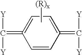
graft 10 of the present invention includesgraft 12. In one aspect of the present invention thegraft 12 is a vacuum deposited polymeric material. Desirably, the polymeric material is a poly-para-xylylene material. A poly-p-xylylene has the following repeating units:
- wherein n is 10-10,000, x is an integer from 0 to 4, Y, which can be the same or different, is hydrogen or halogen, and R is an aromatic nuclear substituent. Each substituent group R can be the same or different and can be any inert organic or inorganic group which can normally be substituted on aromatic nuclei. Such substituent groups include alkyl, aryl, alkenyl, amino, cyano, carboxyl, alkoxy, hydroxylalkyl, carbalkoxy and like radicals as well as inorganic radicals such as hydroxyl, nitro, halogen and other similar groups which are normally substitutable on aromatic nuclei. Desirably, the substituted groups are lower alkyl hydrocarbons, such as methyl, ethyl, propyl, butyl and hexyl; lower aryl hydrocarbons, such as phenyl, alkylated phenyl, naphthyl and like groups having no more than about 10 carbons; and halogen groups, such as chlorine, bromine, iodine and fluorine. More desirably, the substituted groups are chlorine groups.
- Moreover, compositions having less than complete R group substitution, i.e., where x<4, are useful with the practice of the present invention. Desirably, the less than completely substituted materials include poly-para-xylylene; or Parylene N, wherein x equals 0 and Y equals hydrogen; poly-chloro-para-xylylene or Parylene C, wherein x equals 1, R represents chlorine and Y is hydrogen; and poly-dichloro-para-xylylene or Parylene D, wherein x equals 2, both R's represent chlorine and Y is hydrogen. These desirable materials are shown below, as follows:

- wherein n is as described above.
- The above-described polymers may be formed by vaporization, pyrolysis and vapor deposition of a dimer or a di-para-xylylene having the following general formula:

- wherein Y, R and x are defined above and further wherein R can be the same or different and x can be the same or different. When R and/or x are different, a copolymer may be formed.
- Desirably, the dimers include di-para-xylylene (dimer for parylene N), wherein x equals 0 and Y equals hydrogen; di-chloro-di-para-xylylene (dimer for Parylene C), wherein x equals 1, both R's represent chlorine and Y is hydrogen; and tetra-chloro-di-para-xylylene (dimer for Parylene D), wherein x equals 2, all R's represent chlorine and Y is hydrogen.
- The above-described polymeric material may be formed from commercially available dimer compositions sold by Specialty Coating Systems, IN. Devices for the vacuum vapor deposition of the above-described poly-para-xylylenes are also available from Specialty Coating Systems, IN. Parylene, parylene N, parylene C and parylene D are generic names for the above-described linear poly-para-xylylene polymers.
- The dimers are typically solid at room temperature. The dimers are first vaporized at a temperature of approximately 150° C. or greater. The vaporization may be done at any convenient pressure, but subatmospheric pressures are desirable. For instance pressures of 0.001 to 10 millimeters Hg are desirable. More desirably, the pressure is at about 1 millimeter Hg.
- The pyrolysis of the vaporous di-para-xylylene dimers occurs upon heating the dimers from about 450° C. to about 700° C. The pyrolysis of the di-para-xylylene dimers begins at about 450° C. and involves the cleavage of the dimers at the two methylene-methylene bonds to yield monomeric diradical para-xylylene, as shown below.
- At temperatures above 700° C. cleavage of the constituent groups can occur resulting in a tri- or polyfunctional species causing cross linking or highly branched polymers. Desirably, a pyrolsis temperature of about 680° C. is used. It is desirable that reduced or subatmosphere pressures be employed during pyrolysis. Pressures within the range of 0.001 to 10 millimeters Hg are useful. Desirably, the pyrolysis pressure is slightly lower than the vaporization pressure. Desirably, a pyrolsis pressure of about 0.5 millimeters Hg is used. Furthermore, inert inorganic vapor diluents, such as nitrogen, argon, carbon dioxide and the like, can be employed to vary the temperature of operation or to change the total effective pressure of the system.
- The diradicals formed in the manner described above are made to impinge upon a surface of a target material having a surface temperature below about 100° C. The temperature is advantageously below the condensation temperature of the diradicals present. The diradicals condense on the target surface and spontaneously polymerize thereat. A surface temperature of about room temperature or about 25° C. may suitably be used. The deposition is also typically done at a subatomspheric pressure, for instance about 0.001 to 10 millimeters Hg, or, desirably, at about 0.1 millimeters Hg.
- The above-described subatmospheric pressures can be achieved by any convenient means, for instance through the use of a mechanical vacuum pump. A cold trap at about −70° C. is typically used to collect any non-deposited vaporous para-xylylenes.
- FIG. 8 depicts a schematic flowchart for the method of the present invention for producing the inventive stent-graft. At
step 40, a di-para-xylylene source material or dimer is selected. Desirably, the source materials or dimers include, but are not limited to, the above-described di-para-xylylene, di-chloro-di-para-xylylene, tetra-chloro-di-para-xylylene and combinations thereof. Atstep 42, the selected source material or dimer is vaporized. Desirably, the vaporization of the source material is at conditions described above, for instance at about 150° C. and at about 1.0 mm Hg. Atstep 44, the vaporized source material is pyrolyzed into diradicals. Desirably, the pyrolysis is at conditions described above, for instance at about 680° C. and at about 0.5 mm Hg. Atstep 46, the pyrolyzed source material is deposited onto a target. Desirably, the deposition is at room temperature and low pressure, for instance at about 25° C. and at about 0.1 mm Hg. - The deposited diradicals polymerize to form a poly-para-xylylene material. The deposition may be controlled to yield a material of any desirably thickness. For instance deposited material may be from about 5 microns to about 250 microns in thickness or depth. Desirably, the thickness of the deposited material is from about 10 microns to about 250 microns. More desirably, the thickness is from about 10 microns to about 100 microns. Even more desirably, the thickness is from about 10 microns to about 50 microns. As described below in further detail, a graft may be made of poly-para-xylylenes having a wall thickness of such dimensions.
- Grafts having such thin walls of poly-para-xylylene are useful with the practice of the present invention. Tubes formed by extruding polymeric materials often have a wall thickness of several millimeters or several thousand microns. For example, even so-called thin tubes formed by extruding polytetrafluoroethylene often have a minimum wall thickness of 2 to 3 millimeters. Expanded polytetrafluoroethylene has been extruded to yield tubes with lower wall dimensions, such as about 200 microns or less. Such thin-walled expanded polytetrafluoroethylene tubes, however, are not self-supporting, i.e., they cannot maintain their tubular shape without some type of mechanical support. The lack of the self-supporting feature makes these tubes more difficult to process and handle as compared to self-supporting tubes.
- In contrast, grafts of the present invention are thin-walled, i.e., less than 250 microns, and are self-supporting. Grafts of the present invention made from poly-para-xylylenes are self-supporting even with a wall thickness from about 10 to about 50 microns.
- At
steps stent 14 of the present invention, the target is coated with a layer of poly-para-xylylene and removed from the deposition chamber. Advantageously, all exposed surfaces of the target are substantially coated with poly-para-xylylene. The thickness of the coating can be controlled to any desirable range, for instance from about 10 microns to about 50 microns. - At
steps graft 62, a substantially tubular structure, is deposited ontomandrel 60.Graft 62 is removed frommandrel 60 by any convenient means. For example,graft 62 may be simply slid off themandrel 60. Alternatively,mandrel 60 may be a radially contractible mandrel, such as a length of silastic tubing. Upon contraction of themandrel 60, thegraft 62 is released therefrom. Advantageously,graft 62 is a self-supporting graft to facilitate its removal from themandrel 60. - The present invention is not, however, limited to the use of contractible mandrels, and other mandrels may be suitable used. For example,
mandrel 60 may be a rigid tube made from glass, metal or polymeric material. Themandrel 62 may have a coating of arelease agent 64 on its surface to facilitate the removal of thegraft 62 from themandrel 60. Therelease agent 64 may be a lubricious material, such as a silicone, that permits the sliding disengagement of thegraft 62 frommandrel 60. Alternatively, therelease agent 64 may be a water soluble material that upon contact with water aids in the release of thegraft 62 from themandrel 60. A water soluble polymer, such as a polyacrylamide, may be suitably used. Other water soluble polymers include, but are not limited to, polyvinylalcohol, polyethylene oxide, polyethylene glycol, cellulose based polymers, polyvinyl pyrrolidone, polyvinylamine or polyetheleimine. Furthermore, therelease agent 64, or even themandrel 60, made be made from a low melting point material, such as a wax, which melts upon the application of low levels of heat to facilitate the removal of thegraft 62. Even furthermore, themandrel 60 may be dissolved by an acid thereby releasing thegraft 62. - The poly-para-xylylene tubular structure or graft is used to form the stent-
graft 10 of the present invention.Graft 12 may be disposed withinstent 14 by slidingly engaging the two members as shown by the vectors in FIG. 2. Portions ofstent 14 are securably attached to portions ofgraft 12 to form the stent-graft 10 of the present invention. Securement may be done by any convenient means. Desirably, the vapor deposition of additional poly-para-xylylene material is used to join portions of thestent 14 and thegraft 12 to one and the other. Alternatively, an adhesive, such as a silicone or a urethane, may be used to adhesively bond such portions. Furthermore, such portions may be fused together through the use of heat, the use of a solvent, or combinations thereof. For example, parylene C may be dissolved in high boiling liquids, such as chloronaphthelene or benzolyl benzoate at temperatures above about 150° C. and used to bond the stent to the graft. - Moreover, securement of
graft 12 andstent 14 may be accomplished through mechanical means. Desirably, such mechanical means do not puncture thegraft 12. A locking ring may be disposed on one end or both ends of stent-graft 10, or even at portions thereinbetween. Such a locking ring may be placed over portions of thestent 14 andgraft 12 and secured thereat. For example, a locking ring of poly-para-xylylene could be deposited or placed onto stent-graft 10. The locking ring could be physically attached thereto by any one of the above-described techniques, such as vapor deposition, adhesive bonding and fusing. - FIG. 11 is a cross-sectional view of stent-
graft 10 taken along the 11-11axis showing graft 12 disposed withinstent 14. In another aspect of the present invention,graft 13, as depicted in a cross-sectional view in FIG. 12, is disposed onto outer surfaces ofstent 14. In yet another aspect of the present invention, stent-graft 10 includes aluminal graft 12, astent 14 and anexterior graft 13, as depicted in a cross-sectional view in FIG. 11. Portions ofgrafts stent 14 may be securably attached to one and the other by any of the above-described techniques. In yet another aspect of the present invention a graft, such asgraft 12, made from a poly-para-xylylene material by the above-described methods is useful as an implantable prosthesis. Such a graft is self-supporting while having a wall thickness only of about 10 microns to about 250 microns. - The invention may be further understood with reference to the following non-limiting examples.
- Parylene C Stent-graft
- A tubular graft with a wall thick of about one half to one thousandth of an inch, or about 10 to 25 microns, was formed by vacuum vapor of parylene C. A dimer of di-chloro-di-p-xylylene, which is commercially available from Specialty Coating Systems, Inc., IN, was placed into a vaporization chamber within a vacuum deposition system. The pressure of the system was reduced to about 0.1 torr by means of a mechanical vacuum pump.
- The dimer vaporized at about xylylene, 150° C. and at about 1.0 torr. The vaporized dimer entered a pyrolysis chamber. The pyrolysis chamber was at about 680° C. and about 0.5 torr. The vaporized dimer was pyrolyzed into diradicals. The diradicals entered a rotating deposition chamber having a mandrel. The deposition chamber was operated at about 25° C. and about 0.1 torr. The diradicals were directed towards the outer cylindrical surfaces of the mandrel. The outer cylindrical surface of the mandrel was completely coated with parylene C. The parylene coating was removed from the mandrel to produce a self-supporting graft.
- A portion of the graft was placed on a mandrel. A radially expandable stent in its expanded state was placed over the graft. The mandrel containing the graft and the stent were placed in the deposition chamber. Additional parylene C was deposited. After removal from the deposition system the graft was securably attached to the stent by the additional deposited parylene material.
- While the present invention was described as a stent-graft, other implantable devices are within the spirit of the present invention. For example, any implantable device having an open lattice and a poly-para-xylylene covering or lining over portions of the open lattice may be made by the practice of the present invention. For example, a carotid filter having an open lattice structure and having a base cone covered by a poly-para-xylylene cover having micro-drilled holes would be one example of such an implantable device. Moreover, the present is not limited to implantable devices, and any device, medical or non-medical, having a poly-para-xylylene coating or covering across an open cell may be made by the practice of the present invention.
- Although illustrative aspects of the present invention have been described herein with reference to the accompanying drawings, it is to be understood that the invention is not limited to those precise aspects, and that various other changes and modifications may be effected therein by one skilled in the art without departing from the scope or spirit of the invention.
Claims (32)


Priority Applications (2)
| Application Number | Priority Date | Filing Date | Title |
|---|---|---|---|
| US10/003,149 US7179283B2 (en) | 2001-11-02 | 2001-11-02 | Vapor deposition process for producing a stent-graft and a stent-graft produced therefrom |
| PCT/US2002/029430 WO2003039617A1 (en) | 2001-11-02 | 2002-09-17 | Vapor deposition process for producing a stent-graft |
Applications Claiming Priority (1)
| Application Number | Priority Date | Filing Date | Title |
|---|---|---|---|
| US10/003,149 US7179283B2 (en) | 2001-11-02 | 2001-11-02 | Vapor deposition process for producing a stent-graft and a stent-graft produced therefrom |
Publications (2)
| Publication Number | Publication Date |
|---|---|
| US20030093141A1 true US20030093141A1 (en) | 2003-05-15 |
| US7179283B2 US7179283B2 (en) | 2007-02-20 |
Family
ID=21704412
Family Applications (1)
| Application Number | Title | Priority Date | Filing Date |
|---|---|---|---|
| US10/003,149 Expired - Fee Related US7179283B2 (en) | 2001-11-02 | 2001-11-02 | Vapor deposition process for producing a stent-graft and a stent-graft produced therefrom |
Country Status (2)
| Country | Link |
|---|---|
| US (1) | US7179283B2 (en) |
| WO (1) | WO2003039617A1 (en) |
Cited By (33)
| Publication number | Priority date | Publication date | Assignee | Title |
|---|---|---|---|---|
| US20030040790A1 (en) * | 1998-04-15 | 2003-02-27 | Furst Joseph G. | Stent coating |
| WO2004011051A1 (en) * | 2002-07-29 | 2004-02-05 | Potencia Medical Ag | Durable implant |
| WO2004034874A2 (en) * | 2002-10-15 | 2004-04-29 | Norbert Thompson | Parylene-coated silicone t-tubes and method of use thereof |
| US20040133219A1 (en) * | 2002-07-29 | 2004-07-08 | Peter Forsell | Multi-material constriction device for forming stoma opening |
| US20040225346A1 (en) * | 2003-02-05 | 2004-11-11 | Mazumder Mark M. | Encased stent |
| US20050038472A1 (en) * | 2002-07-31 | 2005-02-17 | Icon Interventional Systems, Inc. | Sutures and surgical staples for anastamoses, wound closures, and surgical closures |
| US20050165476A1 (en) * | 2004-01-23 | 2005-07-28 | Furst Joseph G. | Vascular grafts with amphiphilic block copolymer coatings |
| US20050171596A1 (en) * | 2004-02-03 | 2005-08-04 | Furst Joseph G. | Stents with amphiphilic copolymer coatings |
| US20050276835A1 (en) * | 2004-04-30 | 2005-12-15 | Joerg Lahann | Photo-reactive polymer platform for use in biomedical devices |
| US20060020323A1 (en) * | 2002-11-25 | 2006-01-26 | Boyle Christopher T | Implantable expandable medical devices having regions of differential mechanical properties and methods of making same |
| US20060094926A1 (en) * | 2002-07-29 | 2006-05-04 | Peter Forsell | Multi-material penis constriction device |
| US20060136051A1 (en) * | 1998-07-27 | 2006-06-22 | Icon Interventional Systems, Inc. | Coated medical device |
| US20060193892A1 (en) * | 2001-10-26 | 2006-08-31 | Icon Medical Corp. | Polymer biodegradable medical device |
| US20060200226A1 (en) * | 2005-03-03 | 2006-09-07 | Icon Medical Corp. | Metal alloys for medical devices |
| US20060201601A1 (en) * | 2005-03-03 | 2006-09-14 | Icon Interventional Systems, Inc. | Flexible markers |
| US20060224237A1 (en) * | 2005-03-03 | 2006-10-05 | Icon Medical Corp. | Fragile structure protective coating |
| US20060264914A1 (en) * | 2005-03-03 | 2006-11-23 | Icon Medical Corp. | Metal alloys for medical devices |
| US20070276486A1 (en) * | 2006-05-25 | 2007-11-29 | E. Benson Hood Laboratories | Coated tracheostomy tube and stoma stent or cannula |
| US20080045783A1 (en) * | 2002-07-29 | 2008-02-21 | Peter Forsell | Multi-material incontinence treatment construction device |
| US20080167724A1 (en) * | 2006-12-18 | 2008-07-10 | Med Institute, Inc. | Stent graft with releasable therapeutic agent and soluable coating |
| US20090177268A1 (en) * | 2008-01-07 | 2009-07-09 | Micrus Endovascular Corporation | Radiopaque super-elastic intravascular stent |
| US20090200177A1 (en) * | 2005-03-03 | 2009-08-13 | Icon Medical Corp. | Process for forming an improved metal alloy stent |
| US8070796B2 (en) | 1998-07-27 | 2011-12-06 | Icon Interventional Systems, Inc. | Thrombosis inhibiting graft |
| US8100963B2 (en) | 2001-10-26 | 2012-01-24 | Icon Medical Corp. | Biodegradable device |
| WO2012151405A3 (en) * | 2011-05-03 | 2013-01-17 | Palmaz Scientific, Inc. | Endoluminal implantable surfaces and method of making the same |
| US8603158B2 (en) | 1998-04-15 | 2013-12-10 | Icon Interventional Systems, Inc | Irradiated stent coating |
| KR101438742B1 (en) | 2012-11-22 | 2014-09-05 | 주식회사 엘티에스 | Stent and Manufacturing Method Thereof |
| US9034245B2 (en) | 2010-03-04 | 2015-05-19 | Icon Medical Corp. | Method for forming a tubular medical device |
| CN104780871A (en) * | 2012-10-31 | 2015-07-15 | W.L.戈尔及同仁股份有限公司 | Devices and methods related to deposited support structures |
| US9107899B2 (en) | 2005-03-03 | 2015-08-18 | Icon Medical Corporation | Metal alloys for medical devices |
| US11160675B2 (en) * | 2017-03-24 | 2021-11-02 | Oxford Endovascular Ltd. | Delivery system for deploying a self-expanding tube, and method of deploying a self-expanding tube |
| US11766506B2 (en) | 2016-03-04 | 2023-09-26 | Mirus Llc | Stent device for spinal fusion |
| US11779685B2 (en) | 2014-06-24 | 2023-10-10 | Mirus Llc | Metal alloys for medical devices |
Families Citing this family (7)
| Publication number | Priority date | Publication date | Assignee | Title |
|---|---|---|---|---|
| US7846202B2 (en) * | 1995-06-07 | 2010-12-07 | Cook Incorporated | Coated implantable medical device |
| US6939376B2 (en) * | 2001-11-05 | 2005-09-06 | Sun Biomedical, Ltd. | Drug-delivery endovascular stent and method for treating restenosis |
| US7682387B2 (en) | 2002-04-24 | 2010-03-23 | Biosensors International Group, Ltd. | Drug-delivery endovascular stent and method for treating restenosis |
| US20040024450A1 (en) * | 2002-04-24 | 2004-02-05 | Sun Biomedical, Ltd. | Drug-delivery endovascular stent and method for treating restenosis |
| US8974622B2 (en) | 2010-12-28 | 2015-03-10 | Boston Scientific Scimed, Inc. | Composite ePTFE-silicone covering for stent |
| DE102011103737A1 (en) * | 2011-05-31 | 2012-12-06 | Heinz Busch | Method of coating inner surfaces of elongate objects |
| CA3027591C (en) | 2016-06-23 | 2023-08-01 | Poly-Med, Inc. | Medical implants having managed biodegradation |
Citations (26)
| Publication number | Priority date | Publication date | Assignee | Title |
|---|---|---|---|---|
| US3246627A (en) * | 1962-10-05 | 1966-04-19 | Union Carbide Corp | Apparatus for vapor deposition |
| US3405117A (en) * | 1964-12-24 | 1968-10-08 | Union Carbide Corp | alpha-chloro-di-p-xylylenes |
| US4734300A (en) * | 1986-03-14 | 1988-03-29 | Hughes Aircraft Company | Methods for removing parylene coatings from predetermined, desired areas of a substrate |
| US4863762A (en) * | 1987-03-31 | 1989-09-05 | Central Glass Company, Limited | Method of forming coating film of fluororesin by physical vapor deposition |
| US4945856A (en) * | 1988-06-23 | 1990-08-07 | Jeffrey Stewart | Parylene deposition chamber |
| US5078091A (en) * | 1988-06-23 | 1992-01-07 | Jeffrey Stewart | Parylene deposition chamber and method of use |
| US5258042A (en) * | 1991-12-16 | 1993-11-02 | Henry Ford Health System | Intravascular hydrogel implant |
| US5268033A (en) * | 1991-07-01 | 1993-12-07 | Jeffrey Stewart | Table top parylene deposition chamber |
| US5383928A (en) * | 1992-06-10 | 1995-01-24 | Emory University | Stent sheath for local drug delivery |
| US5395390A (en) * | 1992-05-01 | 1995-03-07 | The Beth Israel Hospital Association | Metal wire stent |
| US5464450A (en) * | 1991-10-04 | 1995-11-07 | Scimed Lifesystems Inc. | Biodegradable drug delivery vascular stent |
| US5609629A (en) * | 1995-06-07 | 1997-03-11 | Med Institute, Inc. | Coated implantable medical device |
| US5637113A (en) * | 1994-12-13 | 1997-06-10 | Advanced Cardiovascular Systems, Inc. | Polymer film for wrapping a stent structure |
| US5669930A (en) * | 1994-12-08 | 1997-09-23 | Fuji Systems Corporation | Stent for intracorporeal retention |
| US5716410A (en) * | 1993-04-30 | 1998-02-10 | Scimed Life Systems, Inc. | Temporary stent and method of use |
| US5779732A (en) * | 1997-03-31 | 1998-07-14 | Medtronic, Inc. | Method and apparatus for implanting a film with an exandable stent |
| US5824049A (en) * | 1995-06-07 | 1998-10-20 | Med Institute, Inc. | Coated implantable medical device |
| US5834005A (en) * | 1992-02-24 | 1998-11-10 | Encelle, Inc. | Bioartificial devices and cellular matrices therefor |
| US5882725A (en) * | 1997-07-01 | 1999-03-16 | Para Tech Coating, Inc. | Parylene deposition chamber including eccentric part tumbler |
| US5922339A (en) * | 1998-01-27 | 1999-07-13 | Usala; Anton-Lewis | Compositions and methods for biocompatible implants |
| US6156435A (en) * | 1996-05-06 | 2000-12-05 | Massachusetts Institute Of Technology | Chemical vapor deposition of fluorocarbon polymer thin films |
| US6290720B1 (en) * | 1998-11-16 | 2001-09-18 | Endotex Interventional Systems, Inc. | Stretchable anti-buckling coiled-sheet stent |
| US20030082324A1 (en) * | 2001-10-30 | 2003-05-01 | Scimed Life Systems, Inc. | Green fluoropolymer tube and endovascular prosthesis formed using same |
| US20030082323A1 (en) * | 2001-10-30 | 2003-05-01 | Scimed Life Systems, Inc. | Apparatus and method for extrusion of thin-walled tubes |
| US6673102B1 (en) * | 1999-01-22 | 2004-01-06 | Gore Enterprises Holdings, Inc. | Covered endoprosthesis and delivery system |
| US6695833B1 (en) * | 2000-09-27 | 2004-02-24 | Nellix, Inc. | Vascular stent-graft apparatus and forming method |
Family Cites Families (15)
| Publication number | Priority date | Publication date | Assignee | Title |
|---|---|---|---|---|
| US4503569A (en) | 1983-03-03 | 1985-03-12 | Dotter Charles T | Transluminally placed expandable graft prosthesis |
| US4580568A (en) | 1984-10-01 | 1986-04-08 | Cook, Incorporated | Percutaneous endovascular stent and method for insertion thereof |
| ES8705239A1 (en) | 1984-12-05 | 1987-05-01 | Medinvent Sa | A device for implantation and a method of implantation in a vessel using such device. |
| US4733665C2 (en) | 1985-11-07 | 2002-01-29 | Expandable Grafts Partnership | Expandable intraluminal graft and method and apparatus for implanting an expandable intraluminal graft |
| US4886062A (en) | 1987-10-19 | 1989-12-12 | Medtronic, Inc. | Intravascular radially expandable stent and method of implant |
| US4856561A (en) | 1987-11-10 | 1989-08-15 | Hydro Conduit Corporation | Seal construction for bell and spigot pipe |
| JPH026832A (en) * | 1988-06-24 | 1990-01-11 | Daikin Ind Ltd | Porous hollow fiber of polytetrafluoroethylene and production thereof |
| CA2147813A1 (en) | 1994-04-28 | 1995-10-29 | Richard Dixon | Intravascular prosthesis with anti-thrombogenic coating |
| WO1998017331A1 (en) | 1995-06-07 | 1998-04-30 | Cook Incorporated | Silver implantable medical device |
| GB9516927D0 (en) | 1995-08-18 | 1995-10-18 | Secr Defence | Preparation of structural materials by nanoscale laminar pvd process |
| EP0862664B1 (en) | 1995-10-27 | 2003-01-02 | Specialty Coating Systems, Inc. | Method and apparatus for the deposition of parylene af4 onto semiconductor wafers |
| TW297147B (en) | 1995-10-27 | 1997-02-01 | Specialty Coating Systems Inc | Multi-level circuit structure including fluorinated parylene polymer dielectric interlayers |
| JP4422215B2 (en) | 1997-02-20 | 2010-02-24 | クック インコーポレイテッド | Coated implantable medical device |
| US6096175A (en) | 1998-07-17 | 2000-08-01 | Micro Therapeutics, Inc. | Thin film stent |
| AU771367B2 (en) | 1998-08-20 | 2004-03-18 | Cook Medical Technologies Llc | Coated implantable medical device |
-
2001
- 2001-11-02 US US10/003,149 patent/US7179283B2/en not_active Expired - Fee Related
-
2002
- 2002-09-17 WO PCT/US2002/029430 patent/WO2003039617A1/en not_active Application Discontinuation
Patent Citations (29)
| Publication number | Priority date | Publication date | Assignee | Title |
|---|---|---|---|---|
| US3246627A (en) * | 1962-10-05 | 1966-04-19 | Union Carbide Corp | Apparatus for vapor deposition |
| US3405117A (en) * | 1964-12-24 | 1968-10-08 | Union Carbide Corp | alpha-chloro-di-p-xylylenes |
| US4734300A (en) * | 1986-03-14 | 1988-03-29 | Hughes Aircraft Company | Methods for removing parylene coatings from predetermined, desired areas of a substrate |
| US4863762A (en) * | 1987-03-31 | 1989-09-05 | Central Glass Company, Limited | Method of forming coating film of fluororesin by physical vapor deposition |
| US4945856A (en) * | 1988-06-23 | 1990-08-07 | Jeffrey Stewart | Parylene deposition chamber |
| US5078091A (en) * | 1988-06-23 | 1992-01-07 | Jeffrey Stewart | Parylene deposition chamber and method of use |
| US5268033A (en) * | 1991-07-01 | 1993-12-07 | Jeffrey Stewart | Table top parylene deposition chamber |
| US5464450A (en) * | 1991-10-04 | 1995-11-07 | Scimed Lifesystems Inc. | Biodegradable drug delivery vascular stent |
| US5258042A (en) * | 1991-12-16 | 1993-11-02 | Henry Ford Health System | Intravascular hydrogel implant |
| US5834005A (en) * | 1992-02-24 | 1998-11-10 | Encelle, Inc. | Bioartificial devices and cellular matrices therefor |
| US5395390A (en) * | 1992-05-01 | 1995-03-07 | The Beth Israel Hospital Association | Metal wire stent |
| US5383928A (en) * | 1992-06-10 | 1995-01-24 | Emory University | Stent sheath for local drug delivery |
| US5716410A (en) * | 1993-04-30 | 1998-02-10 | Scimed Life Systems, Inc. | Temporary stent and method of use |
| US5669930A (en) * | 1994-12-08 | 1997-09-23 | Fuji Systems Corporation | Stent for intracorporeal retention |
| US5700286A (en) * | 1994-12-13 | 1997-12-23 | Advanced Cardiovascular Systems, Inc. | Polymer film for wrapping a stent structure |
| US5637113A (en) * | 1994-12-13 | 1997-06-10 | Advanced Cardiovascular Systems, Inc. | Polymer film for wrapping a stent structure |
| US5824049A (en) * | 1995-06-07 | 1998-10-20 | Med Institute, Inc. | Coated implantable medical device |
| US5609629A (en) * | 1995-06-07 | 1997-03-11 | Med Institute, Inc. | Coated implantable medical device |
| US5873904A (en) * | 1995-06-07 | 1999-02-23 | Cook Incorporated | Silver implantable medical device |
| US6096070A (en) * | 1995-06-07 | 2000-08-01 | Med Institute Inc. | Coated implantable medical device |
| US6156435A (en) * | 1996-05-06 | 2000-12-05 | Massachusetts Institute Of Technology | Chemical vapor deposition of fluorocarbon polymer thin films |
| US5779732A (en) * | 1997-03-31 | 1998-07-14 | Medtronic, Inc. | Method and apparatus for implanting a film with an exandable stent |
| US5882725A (en) * | 1997-07-01 | 1999-03-16 | Para Tech Coating, Inc. | Parylene deposition chamber including eccentric part tumbler |
| US5922339A (en) * | 1998-01-27 | 1999-07-13 | Usala; Anton-Lewis | Compositions and methods for biocompatible implants |
| US6290720B1 (en) * | 1998-11-16 | 2001-09-18 | Endotex Interventional Systems, Inc. | Stretchable anti-buckling coiled-sheet stent |
| US6673102B1 (en) * | 1999-01-22 | 2004-01-06 | Gore Enterprises Holdings, Inc. | Covered endoprosthesis and delivery system |
| US6695833B1 (en) * | 2000-09-27 | 2004-02-24 | Nellix, Inc. | Vascular stent-graft apparatus and forming method |
| US20030082324A1 (en) * | 2001-10-30 | 2003-05-01 | Scimed Life Systems, Inc. | Green fluoropolymer tube and endovascular prosthesis formed using same |
| US20030082323A1 (en) * | 2001-10-30 | 2003-05-01 | Scimed Life Systems, Inc. | Apparatus and method for extrusion of thin-walled tubes |
Cited By (53)
| Publication number | Priority date | Publication date | Assignee | Title |
|---|---|---|---|---|
| US8114152B2 (en) | 1998-04-15 | 2012-02-14 | Icon Interventional Systems, Inc. | Stent coating |
| US20030040790A1 (en) * | 1998-04-15 | 2003-02-27 | Furst Joseph G. | Stent coating |
| US20090062904A1 (en) * | 1998-04-15 | 2009-03-05 | Icon Interventional Systems, Inc. | Stent coating |
| US8603158B2 (en) | 1998-04-15 | 2013-12-10 | Icon Interventional Systems, Inc | Irradiated stent coating |
| US20060136051A1 (en) * | 1998-07-27 | 2006-06-22 | Icon Interventional Systems, Inc. | Coated medical device |
| US8070796B2 (en) | 1998-07-27 | 2011-12-06 | Icon Interventional Systems, Inc. | Thrombosis inhibiting graft |
| US7967855B2 (en) | 1998-07-27 | 2011-06-28 | Icon Interventional Systems, Inc. | Coated medical device |
| US8100963B2 (en) | 2001-10-26 | 2012-01-24 | Icon Medical Corp. | Biodegradable device |
| US8740973B2 (en) | 2001-10-26 | 2014-06-03 | Icon Medical Corp. | Polymer biodegradable medical device |
| US20060193892A1 (en) * | 2001-10-26 | 2006-08-31 | Icon Medical Corp. | Polymer biodegradable medical device |
| US20080045783A1 (en) * | 2002-07-29 | 2008-02-21 | Peter Forsell | Multi-material incontinence treatment construction device |
| US20060111791A1 (en) * | 2002-07-29 | 2006-05-25 | Peter Forsell | Durable implant |
| WO2004011051A1 (en) * | 2002-07-29 | 2004-02-05 | Potencia Medical Ag | Durable implant |
| US20060094926A1 (en) * | 2002-07-29 | 2006-05-04 | Peter Forsell | Multi-material penis constriction device |
| US9427301B2 (en) | 2002-07-29 | 2016-08-30 | Peter Forsell | Durable implant |
| US9278158B2 (en) | 2002-07-29 | 2016-03-08 | Peter Forsell | Multi-material incontinence treatment construction device |
| US20040133219A1 (en) * | 2002-07-29 | 2004-07-08 | Peter Forsell | Multi-material constriction device for forming stoma opening |
| US20050038472A1 (en) * | 2002-07-31 | 2005-02-17 | Icon Interventional Systems, Inc. | Sutures and surgical staples for anastamoses, wound closures, and surgical closures |
| US8016881B2 (en) | 2002-07-31 | 2011-09-13 | Icon Interventional Systems, Inc. | Sutures and surgical staples for anastamoses, wound closures, and surgical closures |
| WO2004034874A2 (en) * | 2002-10-15 | 2004-04-29 | Norbert Thompson | Parylene-coated silicone t-tubes and method of use thereof |
| WO2004034874A3 (en) * | 2002-10-15 | 2004-12-16 | Norbert Thompson | Parylene-coated silicone t-tubes and method of use thereof |
| US11045338B2 (en) | 2002-11-25 | 2021-06-29 | Vactronix Scientific | Implantable expandable medical devices having regions of differential mechanical properties and methods of making same |
| US8529616B2 (en) * | 2002-11-25 | 2013-09-10 | Advanced Bio Prosthetic Surfaces, Ltd., a wholly owned subsidary of Palmaz Scientific, Inc. | Implantable expandable medical devices having regions of differential mechanical properties and methods of making same |
| US9532890B2 (en) | 2002-11-25 | 2017-01-03 | Vactronix Scientific, Inc. | Implantable expandable medical devices having regions of differential mechanical properties and methods of making same |
| US20060020323A1 (en) * | 2002-11-25 | 2006-01-26 | Boyle Christopher T | Implantable expandable medical devices having regions of differential mechanical properties and methods of making same |
| US7311727B2 (en) | 2003-02-05 | 2007-12-25 | Board Of Trustees Of The University Of Arkansas | Encased stent |
| US20040225346A1 (en) * | 2003-02-05 | 2004-11-11 | Mazumder Mark M. | Encased stent |
| US20050165476A1 (en) * | 2004-01-23 | 2005-07-28 | Furst Joseph G. | Vascular grafts with amphiphilic block copolymer coatings |
| US20050171596A1 (en) * | 2004-02-03 | 2005-08-04 | Furst Joseph G. | Stents with amphiphilic copolymer coatings |
| US20050276835A1 (en) * | 2004-04-30 | 2005-12-15 | Joerg Lahann | Photo-reactive polymer platform for use in biomedical devices |
| US20090200177A1 (en) * | 2005-03-03 | 2009-08-13 | Icon Medical Corp. | Process for forming an improved metal alloy stent |
| US8323333B2 (en) | 2005-03-03 | 2012-12-04 | Icon Medical Corp. | Fragile structure protective coating |
| US20060200226A1 (en) * | 2005-03-03 | 2006-09-07 | Icon Medical Corp. | Metal alloys for medical devices |
| US20060201601A1 (en) * | 2005-03-03 | 2006-09-14 | Icon Interventional Systems, Inc. | Flexible markers |
| US20060224237A1 (en) * | 2005-03-03 | 2006-10-05 | Icon Medical Corp. | Fragile structure protective coating |
| US20060264914A1 (en) * | 2005-03-03 | 2006-11-23 | Icon Medical Corp. | Metal alloys for medical devices |
| US9107899B2 (en) | 2005-03-03 | 2015-08-18 | Icon Medical Corporation | Metal alloys for medical devices |
| US8808618B2 (en) | 2005-03-03 | 2014-08-19 | Icon Medical Corp. | Process for forming an improved metal alloy stent |
| US20070276486A1 (en) * | 2006-05-25 | 2007-11-29 | E. Benson Hood Laboratories | Coated tracheostomy tube and stoma stent or cannula |
| US20080167724A1 (en) * | 2006-12-18 | 2008-07-10 | Med Institute, Inc. | Stent graft with releasable therapeutic agent and soluable coating |
| US9474833B2 (en) * | 2006-12-18 | 2016-10-25 | Cook Medical Technologies Llc | Stent graft with releasable therapeutic agent and soluble coating |
| US8597344B2 (en) * | 2008-01-07 | 2013-12-03 | DePuy Synthes Products, LLC | Radiopaque super-elastic intravascular stent |
| US20090177268A1 (en) * | 2008-01-07 | 2009-07-09 | Micrus Endovascular Corporation | Radiopaque super-elastic intravascular stent |
| US8623071B2 (en) | 2008-01-07 | 2014-01-07 | DePuy Synthes Products, LLC | Radiopaque super-elastic intravascular stent |
| US20100152837A1 (en) * | 2008-01-07 | 2010-06-17 | Micrus Endovascular Corporation | Radiopaque super-elastic intravascular stent |
| US9034245B2 (en) | 2010-03-04 | 2015-05-19 | Icon Medical Corp. | Method for forming a tubular medical device |
| WO2012151405A3 (en) * | 2011-05-03 | 2013-01-17 | Palmaz Scientific, Inc. | Endoluminal implantable surfaces and method of making the same |
| US8728563B2 (en) | 2011-05-03 | 2014-05-20 | Palmaz Scientific, Inc. | Endoluminal implantable surfaces, stents, and grafts and method of making same |
| CN104780871A (en) * | 2012-10-31 | 2015-07-15 | W.L.戈尔及同仁股份有限公司 | Devices and methods related to deposited support structures |
| KR101438742B1 (en) | 2012-11-22 | 2014-09-05 | 주식회사 엘티에스 | Stent and Manufacturing Method Thereof |
| US11779685B2 (en) | 2014-06-24 | 2023-10-10 | Mirus Llc | Metal alloys for medical devices |
| US11766506B2 (en) | 2016-03-04 | 2023-09-26 | Mirus Llc | Stent device for spinal fusion |
| US11160675B2 (en) * | 2017-03-24 | 2021-11-02 | Oxford Endovascular Ltd. | Delivery system for deploying a self-expanding tube, and method of deploying a self-expanding tube |
Also Published As
| Publication number | Publication date |
|---|---|
| WO2003039617A1 (en) | 2003-05-15 |
| US7179283B2 (en) | 2007-02-20 |
Similar Documents
| Publication | Publication Date | Title |
|---|---|---|
| US7179283B2 (en) | Vapor deposition process for producing a stent-graft and a stent-graft produced therefrom | |
| US8025693B2 (en) | Stent-graft having flexible geometries and methods of producing the same | |
| US8083790B2 (en) | ePTFE graft-stent composite device | |
| US20070208409A1 (en) | Flexible stent-graft devices and methods of producing the same | |
| JP3927545B2 (en) | Tubular PTFE graft with radially expandable stent | |
| EP1729681B1 (en) | Partially biodegradable stent | |
| JP5129296B2 (en) | Expandable stent | |
| US20170296325A1 (en) | Stent-graft prosthesis and method of manufacture | |
| US20020055768A1 (en) | Method of manufacturing a thin-layered, endovascular, polymer-covered stent device | |
| WO1996027347A1 (en) | Composite intraluminal graft | |
| EP2231214A2 (en) | Flexible stent-graft device having patterned polymeric coverings | |
| AU780445B2 (en) | Biocompatible endoprostheses | |
| EP1345555B1 (en) | Composite tubular prostheses | |
| US8221486B2 (en) | Laminated stent graft edge binding | |
| CA2543816C (en) | Eptfe graft-stent composite device |
Legal Events
| Date | Code | Title | Description |
|---|---|---|---|
| AS | Assignment |
Owner name: BOSTON SCIENTIFIC CORPORATION/SCIMED LIFE SYSTMES, Free format text: ASSIGNMENT OF ASSIGNORS INTEREST;ASSIGNORS:DIMATTEO, KRISTIAN;THISTLE, ROBERT C.;REEL/FRAME:012353/0635 Effective date: 20011023 |
|
| AS | Assignment |
Owner name: SCIMED LIFE SYSTEMS, INC., MINNESOTA Free format text: ASSIGNMENT OF ASSIGNORS INTEREST;ASSIGNORS:BOSTON SCIENTIFIC CORPORATON;SCIMED LIFE SYSTEMS, INC.;REEL/FRAME:012716/0524 Effective date: 20020311 |
|
| AS | Assignment |
Owner name: BOSTON SCIENTIFIC SCIMED, INC., MINNESOTA Free format text: CHANGE OF NAME;ASSIGNOR:SCIMED LIFE SYSTEMS, INC.;REEL/FRAME:018505/0868 Effective date: 20050101 Owner name: BOSTON SCIENTIFIC SCIMED, INC.,MINNESOTA Free format text: CHANGE OF NAME;ASSIGNOR:SCIMED LIFE SYSTEMS, INC.;REEL/FRAME:018505/0868 Effective date: 20050101 |
|
| FEPP | Fee payment procedure |
Free format text: PAYOR NUMBER ASSIGNED (ORIGINAL EVENT CODE: ASPN); ENTITY STATUS OF PATENT OWNER: LARGE ENTITY |
|
| FPAY | Fee payment |
Year of fee payment: 4 |
|
| REMI | Maintenance fee reminder mailed | ||
| LAPS | Lapse for failure to pay maintenance fees | ||
| STCH | Information on status: patent discontinuation |
Free format text: PATENT EXPIRED DUE TO NONPAYMENT OF MAINTENANCE FEES UNDER 37 CFR 1.362 |
|
| FP | Lapsed due to failure to pay maintenance fee |
Effective date: 20150220 |