US20030184123A1 - Industrial vehicle - Google Patents
Industrial vehicle Download PDFInfo
- Publication number
- US20030184123A1 US20030184123A1 US10/402,521 US40252103A US2003184123A1 US 20030184123 A1 US20030184123 A1 US 20030184123A1 US 40252103 A US40252103 A US 40252103A US 2003184123 A1 US2003184123 A1 US 2003184123A1
- Authority
- US
- United States
- Prior art keywords
- armrest
- hood
- industrial vehicle
- vehicle according
- locking member
- Prior art date
- Legal status (The legal status is an assumption and is not a legal conclusion. Google has not performed a legal analysis and makes no representation as to the accuracy of the status listed.)
- Granted
Links
Images


Classifications
-
- B—PERFORMING OPERATIONS; TRANSPORTING
- B66—HOISTING; LIFTING; HAULING
- B66F—HOISTING, LIFTING, HAULING OR PUSHING, NOT OTHERWISE PROVIDED FOR, e.g. DEVICES WHICH APPLY A LIFTING OR PUSHING FORCE DIRECTLY TO THE SURFACE OF A LOAD
- B66F9/00—Devices for lifting or lowering bulky or heavy goods for loading or unloading purposes
- B66F9/06—Devices for lifting or lowering bulky or heavy goods for loading or unloading purposes movable, with their loads, on wheels or the like, e.g. fork-lift trucks
- B66F9/075—Constructional features or details
- B66F9/0759—Details of operating station, e.g. seats, levers, operator platforms, cabin suspension
-
- B—PERFORMING OPERATIONS; TRANSPORTING
- B60—VEHICLES IN GENERAL
- B60N—SEATS SPECIALLY ADAPTED FOR VEHICLES; VEHICLE PASSENGER ACCOMMODATION NOT OTHERWISE PROVIDED FOR
- B60N2/00—Seats specially adapted for vehicles; Arrangement or mounting of seats in vehicles
- B60N2/02—Seats specially adapted for vehicles; Arrangement or mounting of seats in vehicles the seat or part thereof being movable, e.g. adjustable
- B60N2/04—Seats specially adapted for vehicles; Arrangement or mounting of seats in vehicles the seat or part thereof being movable, e.g. adjustable the whole seat being movable
- B60N2/14—Seats specially adapted for vehicles; Arrangement or mounting of seats in vehicles the seat or part thereof being movable, e.g. adjustable the whole seat being movable rotatable, e.g. to permit easy access
- B60N2/143—Seats specially adapted for vehicles; Arrangement or mounting of seats in vehicles the seat or part thereof being movable, e.g. adjustable the whole seat being movable rotatable, e.g. to permit easy access taking a position opposite to the original one
-
- B—PERFORMING OPERATIONS; TRANSPORTING
- B60—VEHICLES IN GENERAL
- B60N—SEATS SPECIALLY ADAPTED FOR VEHICLES; VEHICLE PASSENGER ACCOMMODATION NOT OTHERWISE PROVIDED FOR
- B60N2/00—Seats specially adapted for vehicles; Arrangement or mounting of seats in vehicles
- B60N2/75—Arm-rests
- B60N2/753—Arm-rests movable to an inoperative position
-
- B—PERFORMING OPERATIONS; TRANSPORTING
- B60—VEHICLES IN GENERAL
- B60N—SEATS SPECIALLY ADAPTED FOR VEHICLES; VEHICLE PASSENGER ACCOMMODATION NOT OTHERWISE PROVIDED FOR
- B60N2/00—Seats specially adapted for vehicles; Arrangement or mounting of seats in vehicles
- B60N2/75—Arm-rests
- B60N2/763—Arm-rests adjustable
- B60N2/767—Angle adjustment
-
- B—PERFORMING OPERATIONS; TRANSPORTING
- B60—VEHICLES IN GENERAL
- B60N—SEATS SPECIALLY ADAPTED FOR VEHICLES; VEHICLE PASSENGER ACCOMMODATION NOT OTHERWISE PROVIDED FOR
- B60N2/00—Seats specially adapted for vehicles; Arrangement or mounting of seats in vehicles
- B60N2/75—Arm-rests
- B60N2/763—Arm-rests adjustable
- B60N2/77—Height adjustment
-
- B—PERFORMING OPERATIONS; TRANSPORTING
- B60—VEHICLES IN GENERAL
- B60N—SEATS SPECIALLY ADAPTED FOR VEHICLES; VEHICLE PASSENGER ACCOMMODATION NOT OTHERWISE PROVIDED FOR
- B60N2/00—Seats specially adapted for vehicles; Arrangement or mounting of seats in vehicles
- B60N2/75—Arm-rests
- B60N2/763—Arm-rests adjustable
- B60N2/773—Longitudinal adjustment
-
- B—PERFORMING OPERATIONS; TRANSPORTING
- B60—VEHICLES IN GENERAL
- B60N—SEATS SPECIALLY ADAPTED FOR VEHICLES; VEHICLE PASSENGER ACCOMMODATION NOT OTHERWISE PROVIDED FOR
- B60N2/00—Seats specially adapted for vehicles; Arrangement or mounting of seats in vehicles
- B60N2/75—Arm-rests
- B60N2/79—Adaptations for additional use of the arm-rests
- B60N2/797—Adaptations for additional use of the arm-rests for use as electrical control means, e.g. switches
-
- B—PERFORMING OPERATIONS; TRANSPORTING
- B62—LAND VEHICLES FOR TRAVELLING OTHERWISE THAN ON RAILS
- B62D—MOTOR VEHICLES; TRAILERS
- B62D25/00—Superstructure or monocoque structure sub-units; Parts or details thereof not otherwise provided for
- B62D25/08—Front or rear portions
- B62D25/10—Bonnets or lids, e.g. for trucks, tractors, busses, work vehicles
-
- B—PERFORMING OPERATIONS; TRANSPORTING
- B62—LAND VEHICLES FOR TRAVELLING OTHERWISE THAN ON RAILS
- B62D—MOTOR VEHICLES; TRAILERS
- B62D33/00—Superstructures for load-carrying vehicles
- B62D33/06—Drivers' cabs
Definitions
- the present invention relates to an industrial vehicle such as a forklift truck and more particularly to the industrial vehicle with which a hood is provided, the hood being opened and closed around an end of the hood that functions as a pivotal axis, a seat and an armrest being provided on or above the hood.
- the structure of the armrest provided with the parallel linkage is adopted, the structure of the armrest becomes complicated and furthermore it is hard to secure a relatively large displacement of the armrest. Therefore, the structure of the armrest provided with the parallel linkage is not necessarily suitable as a structure for installing the armrest in the hood for the industrial vehicle.
- the present invention has a following feature.
- An industrial vehicle has a body, a hood and an armrest.
- the hood is installed on or above the body and has an end. The end is a pivotal axis around which the hood is pivoted so that the hood is opened and closed to the body.
- the armrest is installed on or above the hood.
- the armrest has a pivotal axis around which the armrest is pivoted relative to the hood.
- the armrest has a first position and a second position and is displaced between the first position and the second position.
- FIG. 2 is a side view illustrating an opening and closing action of a hood according to the first preferred embodiment of the present invention
- FIG. 3 is a side view illustrating a displacement of an armrest according to the first preferred embodiment of the present invention
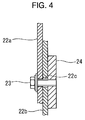
- FIG. 4 is a cross-sectional view illustrating an upper plate, a lower plate, a screw and a nut that are taken along the line A-A in FIG. 3;
- FIG. 6 is a cross-sectional view illustrating a lower plate, a bracket, a pin, a screw and a pivotal shaft that are taken along the line C-C in FIG. 3;
- FIG. 13 is an explanation drawing illustrating an action of the locking member and a displacement of the armrest according to the third preferred embodiment of the present invention.
- FIGS. 1 through 6 An industrial vehicle according to a first preferred embodiment of the present invention will now be described with reference to FIGS. 1 through 6.
- a forklift truck is adopted as the industrial vehicle.
- each shock absorber 6 is pivotally connected to the pillar 4 a at the rear side of the body 1 by an associated pin 6 a .
- the other end thereof is pivotally connected to the side surface of the hood 2 by another associated pin 6 a .
- the seat 3 is fixed to the upper surface of the hood 2 by a bolt which is not shown in the drawings.
- the armrest 20 is placed on the right side of the seat 3 in parallel with the seat 3 .
- a bracket 7 or a support member is erected on the upper surface of the hood 2 for supporting the armrest 20 .
- the armrest body 21 is formed in the shape of box and is substantially in a rectangular shape in a plane view.
- a plurality of operating members 9 is placed on the front end of the armrest body 21 for operating an actuator for loading operation such as a lift cylinder and a tilt cylinder.
- the operating members 9 include a lift lever for raising and lowering a fork, a tilt lever for tilting a mast frontward and rearward, and an attachment lever for operating an attachment attached to a loading device. These levers are placed in a lateral direction of the armrest body 21 .
- a guard 11 is formed on the front end of the armrest body 21 so as to surround the operating members 9 and thus protects the operating members 9 from interfering with an obstacle.
- the plate 22 of the armrest 20 includes an upper plate 22 a and a lower plate 22 b .
- the upper plate 22 a is superimposed on the lower plate 22 b .
- the upper plate 22 a and the lower plate 22 b are tightened by two screws 23 and a nut 24 in the shape of plate.
- a slot 22 c substantially in the shape of E is formed in the lower plate 22 b . Therefore, the position of the upper plate 22 a is adjusted to three heights by loosing the screw 23 and by moving the screw 23 along the slot 22 c.
- the structure for installing the armrest 20 on the bracket 7 will be described.
- the lower end of the lower plate 22 b is installed on the bracket 7 through a pivotal shaft 28 so as to pivot in the front-and-rear direction.
- the armrest 20 is pivotally installed on the bracket 7 and the pivotal center is set at a lower part of the armrest 20 and substantially midway in the front-and-rear direction of the armrest 20 .
- the above-mentioned pivotal center corresponds to the pivotal axis of the armrest 20 .
- the above-mentioned screw 31 having the handle 31 a constitutes a means for fixing the armrest 20 .
- the interference between the head guard 4 , which is originally placed as an obstacle in a trajectory that is drawn by movement of the armrest 20 connected to the hood 2 , and the armrest 20 is avoided by displacing the armrest 20 to the evacuating position.
- the structure of the armrest 20 is simplified as compared to the structure for installing the armrest 20 with a link mechanism.
- FIGS. 7 and 8 An industrial vehicle according to a second preferred embodiment of the present invention will now be described with reference to FIGS. 7 and 8.
- a link 35 is arranged.
- the armrest 20 is displaced between the using position and the evacuating position in connection with an opening and closing action of the hood 2 .
- the link 35 corresponds to an interlocking member.
- a forklift truck according to the second embodiment of the present invention is structurally same as the forklift truck according to the first embodiment of the present invention. Therefore, constituent components common to the first embodiment are added with the same reference numeral on the drawings and overlap of explanation is omitted.
- the link 35 is arranged to some extent above the side surface of the hood 2 so as to extend in the front-and-rear direction.
- One end of the link 35 is pivotally connected to the pillar 4 a at the rear side of the body 1 by a pin 35 a while the other end of the link 35 is pivotally connected to the lower plate 22 b of the armrest 20 by a pin 35 b .
- a connecting point at the side of the rear pillar 4 a of the link 35 or the pin 35 a is positioned to some extent above the hinge 5 that is a pivotal fulcrum of the hood 2 .
- a connecting point at the side of the armrest 20 or the pin 35 b is positioned to some extent beneath the pivotal shaft 28 that is a pivotal fulcrum of the armrest 20 .
- each connecting point of the link 35 to the rear pillar 4 a and the armrest 20 is set in a such manner that a dot chain line O that links the both connecting points, and a dot chain line P that links the pivotal fulcrum of the hood 2 with the pivotal fulcrum of the armrest 20 intersect with each other.
- a turnbuckle 36 is provided with the link 35 for adjusting the length of the link 35 halfway in a longitudinal direction of the link 35 . Therefore, when the link 35 is installed on the rear pillar 4 a or the armrest 20 , unevenness of a connecting position caused by an error of the manufacture of the link 35 is cancelled.
- the armrest 20 is displaced between the using position and the evacuating position in connection with the opening and closing action of the hood 2 , especially without displacing the armrest 20 by operating the armrest 20 . Therefore, operating performance is improved.
- the screw 31 is effective to prevent the armrest 20 from chattering.
- FIGS. 9 through 19 an industrial vehicle according to a third preferred embodiment of the present invention will be described with reference to FIGS. 9 through 19.
- a locking mechanism 40 is adopted in place of the screw 31 provided with the handle 31 a.
- the forklift truck according to the third embodiment of the present invention is structurally same as the forklift truck according to the first embodiment of the present invention. Therefore, constituent components common to the first embodiment are added with the same reference numeral on the drawings and overlap of explanation is omitted.
- the locking mechanism 40 includes a locking pin 41 and a locking member 42 .
- the locking pin 41 is fixed to the bracket 7 and the locking member 42 is installed on the lower plate 22 b of the armrest 20 .
- the locking member 42 is formed substantially in an angular shape and the top of the angular shape is pivotally supported by a shaft 43 .
- Front and rear hooks 42 a whose shape is in the shape of V are provided in the locking member 42 so as to sandwich the shaft 43 at the front and rear sides of the shaft 43 beneath the shaft 43 , respectively.
- the locking member 42 is pivotally supported by the shaft 43 in the middle of the front-and-rear direction thereof.
- the shape at the front and rear sides of the locking member 42 is formed so as to be symmetrical with respect to the shaft 43 . Therefore, in a free state, as shown by a two-dot chain line in FIG. 9, the weight at the front and rear sides of the locking member 42 is balanced and the locking member 42 is horizontal.
- the locking pin 41 extends through the arched slot 22 d formed in the lower plate 22 b and protrudes at the side of the locking member 42 . Thereby, the locking pin 41 is movable relative to the lower plate 22 b along the slot 22 d . Note that the center of curvature of the arched slot 22 d is the pivotal shaft 28 .
- the locking pin 41 engages with the front hook 42 a and thereby locks the armrest 20 so as not to pivot rearward.
- the locking pin 41 holds the front hook 42 a from the top of the front hook 42 a and the locking member 42 is slightly pivoted rearward.
- the locking member 42 is pivoted so as to unlock the locking pin 41 for its tare.
- the armrest 20 is also tilted rearward by its tare.
- a dot chain line Q illustrated in FIGS. 10 through 19 is a central line that divides the locking member 42 into two parts at the front and rear sides. Also, in the locking state, the locking member 42 is tilted rearward relative to the direction of the action of gravity (downward direction).
- the locking member 42 is integrally displaced with the locking pin 41 in a state that the locking member 42 is locked by the locking pin 41 .
- Such an integral displacement is, as shown in FIGS. 11 through 13, a displacement having a direction that the locking member 42 becomes horizontal state (in a direction that an inclination angle of the dot chain line Q relative to the direction of gravity is reduced).
- the locking member 42 pivots on the shaft 43 relative to the armrest 20 in a such manner that the locking member 42 maintains the horizontal state. Thereby, the hook 42 a is unlocked from the locking pin 41 .
- the pivoting force generated due to the tare of the armrest 20 is applied to the armrest 20 itself rearward. Therefore, as the armrest 20 pivots rearward, as shown in FIG. 14, the locking member 42 pivots in a such manner that the hook 42 a of the locking member 42 passes beneath the locking pin 41 . Thus, the locking member 42 is unlocked and thereby the armrest 20 is pivoted rearward.
- the pivoting motion of the armrest 20 is regulated when the engaging portion 22 e of the lower plate 22 b contacts the stopper pin 7 b .
- the armrest 20 is displaced to the evacuating position.
- the hood 2 is opened in a state that the armrest 20 is held at the evacuating position. Therefore, the armrest 20 is moved without interfering with the guard portion 4 b of the head guard 4 .
- the armrest 20 when the hood 2 is opened, the armrest 20 is displaced to the evacuating position only by unlocking the armrest 20 without any other operation. Therefore, interference between the armrest 20 and the guard portion 4 b of the head guard 4 that is caused by forgetting to displace the armrest 20 to the evacuating position is avoided.
- the operating member 9 is formed on the armrest 20 . In alternative embodiments to the preferred embodiments, however, the operating member 9 is not formed on the armrest 20 .
- the working for unlocking the locking member 42 is performed by utilizing the tare of the locking member 42 .
- the locking member 42 is unlocked by using an electric actuator that works based on the opening action of the hood 2 .
Abstract
Description
- The present invention relates to an industrial vehicle such as a forklift truck and more particularly to the industrial vehicle with which a hood is provided, the hood being opened and closed around an end of the hood that functions as a pivotal axis, a seat and an armrest being provided on or above the hood.
- To supply an operator of the forklift truck with a comfortable working environment by reducing fatigue of the operator, such a forklift truck that is provided with an armrest at one side of the seat (at a right side in many cases) is proposed. In the forklift truck, the seat and the armrest for the operator are placed on the hood that covers a battery or an engine. To provide the battery or the engine with service, the hood is structured so as to be opened rearward around the rear end of the hood functioning as a pivotal axis. In such a structure, when the hood is pivoted rearward around the rear end thereof to be opened, if the armrest is arranged so as to protrude more forward than the front end surface of the hood, it is possible that the armrest interferes with a head guard for protecting the operator. Therefore, to prevent the armrest from interfering with the head guard, it is preferred that the armrest is structured so as to vary its position for installing the armrest relative to the hood.
- U.S. Pat. No. 5,941,603 discloses such a structure that an armrest is installed in a vehicle seat so as to be capable of adjusting a position thereof. This armrest according to the Patent is installed in the vehicle seat through a parallel linkage. In this case, the armrest is movable between an upper position at the front side and a lower position at the rear side so as to maintain a parallel state.
- When the structure of the armrest provided with the parallel linkage is adopted, the structure of the armrest becomes complicated and furthermore it is hard to secure a relatively large displacement of the armrest. Therefore, the structure of the armrest provided with the parallel linkage is not necessarily suitable as a structure for installing the armrest in the hood for the industrial vehicle.
- The present invention is directed to an industrial vehicle that has an armrest on a hood of the industrial vehicle where the armrest is structurally simple but also effectively installed in the hood so as to avoid interfering with other parts installed on the industrial vehicle when the hood is opened.
- The present invention has a following feature. An industrial vehicle has a body, a hood and an armrest. The hood is installed on or above the body and has an end. The end is a pivotal axis around which the hood is pivoted so that the hood is opened and closed to the body. The armrest is installed on or above the hood. The armrest has a pivotal axis around which the armrest is pivoted relative to the hood. The armrest has a first position and a second position and is displaced between the first position and the second position.
- The features of the present invention that are believed to be novel are set forth with particularity in the appended claims. The invention, together with objects and advantages thereof, may best be understood by reference to the following description of the presently preferred embodiments together with the accompanying drawings in which:
- FIG. 1 is a partial perspective view illustrating a forklift truck according to a first preferred embodiment of the present invention;
- FIG. 2 is a side view illustrating an opening and closing action of a hood according to the first preferred embodiment of the present invention;
- FIG. 3 is a side view illustrating a displacement of an armrest according to the first preferred embodiment of the present invention;
- FIG. 4 is a cross-sectional view illustrating an upper plate, a lower plate, a screw and a nut that are taken along the line A-A in FIG. 3;
- FIG. 5 is a cross-sectional view illustrating an armrest body and a slide guide that are taken along the line B-B in FIG. 3;
- FIG. 6 is a cross-sectional view illustrating a lower plate, a bracket, a pin, a screw and a pivotal shaft that are taken along the line C-C in FIG. 3;
- FIG. 7 is a side view illustrating a structure for installing an armrest according to a second preferred embodiment of the present invention;
- FIG. 8 is a partial enlarged view illustrating an action of a link according to the second preferred embodiment of the present invention;
- FIG. 9 is a side view illustrating a structure for installing an armrest according to a third preferred embodiment of the present invention;
- FIG. 10 is an explanation drawing illustrating an action of a locking member and a displacement of the armrest according to the third preferred embodiment of the present invention;
- FIG. 11 is an explanation drawing illustrating an action of the locking member and a displacement of the armrest according to the third preferred embodiment of the present invention;
- FIG. 12 is an explanation drawing illustrating an action of the locking member and a displacement of the armrest according to the third preferred embodiment of the present invention;
- FIG. 13 is an explanation drawing illustrating an action of the locking member and a displacement of the armrest according to the third preferred embodiment of the present invention;
- FIG. 14 is an explanation drawing illustrating an action of the locking member and a displacement of the armrest according to the third preferred embodiment of the present invention;
- FIG. 15 is an explanation drawing illustrating an action of the locking member and a displacement of the armrest according to the third preferred embodiment of the present invention;
- FIG. 16 is an explanation drawing illustrating an action of the locking member and a displacement of the armrest according to the third preferred embodiment of the present invention;
- FIG. 17 is an explanation drawing illustrating an action of the locking member and a displacement of the armrest according to the third preferred embodiment of the present invention;
- FIG. 18 is an explanation drawing illustrating an action of the locking member and a displacement of the armrest according to the third preferred embodiment of the present invention; and
- FIG. 19 is an explanation drawing illustrating an action of the locking member and a displacement of the armrest according to the third preferred embodiment of the present invention.
- An industrial vehicle according to a first preferred embodiment of the present invention will now be described with reference to FIGS. 1 through 6. In the first embodiment, a forklift truck is adopted as the industrial vehicle.
- As shown in FIGS. 1 and 2, a
hood 2 is placed on abody 1 of the forklift truck for covering a battery or an engine. Aseat 3 is placed on thehood 2 and anarmrest 20 is placed above thehood 2. An operator sits on theseat 3 and rests his arm on thearmrest 20. A head guard 4 is placed on thebody 1 for guarding the operator against falling objects. The head guard 4 includes fourpillars 4 a and aguard portion 4 b. Thepillars 4 a are erected on thebody 1 to support theguard portion 4 b. Acounterweight 8 is installed on the rear side of thebody 1. The rear end of thehood 2 is installed on the front end of thecounterweight 8 through ahinge 5 in a such manner that thehood 2 pivots on thehinge 5 in a front-and-rear direction of thebody 1. Thus, thehood 2 is opened and closed to thebody 1. In this case, a pivotal fulcrum of thehood 2 corresponds to a pivotal axis of thehood 2. - Referring to FIG. 2, the shock of the
body 1 caused by an opening and closing action of thehood 2 is absorbed by twoshock absorbers 6 each provided at right and left sides. One end of eachshock absorber 6 is pivotally connected to thepillar 4 a at the rear side of thebody 1 by an associatedpin 6 a. The other end thereof is pivotally connected to the side surface of thehood 2 by another associatedpin 6 a. Theseat 3 is fixed to the upper surface of thehood 2 by a bolt which is not shown in the drawings. Thearmrest 20 is placed on the right side of theseat 3 in parallel with theseat 3. Abracket 7 or a support member is erected on the upper surface of thehood 2 for supporting thearmrest 20. - Now referring to FIGS. 3 through 6, the structure of the
armrest 20 and the structure for installing thearmrest 20 on thebracket 7 will be described. Thearmrest 20 includes anarmrest body 21 and anoblong plate 22. Thearmrest body 21 extends in the front-and-rear direction and has a substantially horizontal plane for resting the operator's arm. Theplate 22 installs thearmrest body 21 on thebracket 7. - The
armrest body 21 is formed in the shape of box and is substantially in a rectangular shape in a plane view. A plurality ofoperating members 9 is placed on the front end of thearmrest body 21 for operating an actuator for loading operation such as a lift cylinder and a tilt cylinder. The operatingmembers 9 include a lift lever for raising and lowering a fork, a tilt lever for tilting a mast frontward and rearward, and an attachment lever for operating an attachment attached to a loading device. These levers are placed in a lateral direction of thearmrest body 21. Also, aguard 11 is formed on the front end of thearmrest body 21 so as to surround theoperating members 9 and thus protects theoperating members 9 from interfering with an obstacle. - As shown in FIG. 3, the
plate 22 of thearmrest 20 includes anupper plate 22 a and alower plate 22 b. Theupper plate 22 a is superimposed on thelower plate 22 b. As shown in FIG. 4, theupper plate 22 a and thelower plate 22 b are tightened by twoscrews 23 and anut 24 in the shape of plate. Aslot 22 c substantially in the shape of E is formed in thelower plate 22 b. Therefore, the position of theupper plate 22 a is adjusted to three heights by loosing thescrew 23 and by moving thescrew 23 along theslot 22 c. - As shown in FIG. 5, a
slide guide 25 whose cross sectional shape is substantially rectangular is fixed on the upper end of theupper plate 22 a. Theslide guide 25 extends in the front-and-rear direction. Thearmrest body 21 is placed over theslide guide 25 and supported by theslide guide 25 so as to move in the front-and-rear direction. Aslot 25 a is formed on theslide guide 25 and extends in the front-and-rear direction. A throughbolt 26 is inserted into theslot 25 a of theslide guide 25 through a hole formed in thearmrest body 21. Thearmrest body 21 is fixed to theslide guide 25 by tightening aknob 27 that is installed on one end of the throughbolt 26. Therefore, when theknob 27 is loosened, the position of thearmrest body 21 is adjusted in the front-and-rear direction. Thus, the position of thearmrest body 21 is properly adjusted so as to meet the operator's physique. - Now, the structure for installing the armrest 20 on the
bracket 7 will be described. As shown in FIGS. 3 and 6, the lower end of thelower plate 22 b is installed on thebracket 7 through apivotal shaft 28 so as to pivot in the front-and-rear direction. More specifically, thearmrest 20 is pivotally installed on thebracket 7 and the pivotal center is set at a lower part of thearmrest 20 and substantially midway in the front-and-rear direction of thearmrest 20. In this case, the above-mentioned pivotal center corresponds to the pivotal axis of thearmrest 20. As shown in FIG. 6, acylinder 7 a is fixed to thebracket 7 and abushing 29 is accommodated in thecylinder 7 a so as to slide over thecylinder 7 a. Thepivotal shaft 28 is supported by thebushing 29 so as to slide over thebushing 29 and thus is smoothly pivoted. - An
arched slot 22 d whose center of the curvature is a pivotal fulcrum of thelower plate 22 b is formed on thelower plate 22 b. Apin 30 is fixed to thebracket 7 to function as a nut. Thepin 30 is inserted in theslot 22 d so as to move along theslot 22 d relative to thelower plate 22 b. Ascrew 31 is screwed into a tapped hole of thepin 30 and ahandle 31 a is fixed on thescrew 31. By fastening thescrew 31 to thepin 30, thelower plate 22 b is fixed to thebracket 7. Therefore, in a state that thescrew 31 is loosened to thepin 30, it is possible to pivot the armrest 20 in the front-and-rear direction. At this time, thepin 30 moves along theslot 22 d. The above-mentionedscrew 31 having the handle 31 a constitutes a means for fixing thearmrest 20. - The position where the
armrest 20 is installed relative to thehood 2 is displaced by pivoting thepivotal shaft 28 as the pivotal fulcrum in the front-and-rear direction. When thepivotal shaft 28 is pivoted frontward, thearmrest body 21 is substantially in a horizontal state and the front end of thearmrest body 21 protrudes more frontward than the front end surface of thehood 2. At this time, the position is a using position (illustrated by a solid line in FIG. 3) that is supplied to a use of the operator and corresponds to a first position. If thehood 2 is opened in a state that thearmrest 20 is at the using position, the front end of thearmrest 21 interferes with or contacts theguard portion 4 b of the head guard 4. - On the other hand, when the
pivotal shaft 28 is pivoted rearward, the front end of thearmrest body 21 is positioned more rearward than the front end surface of thehood 2. This position is an evacuating position (illustrated by a two-dot chain line in FIG. 3) and corresponds to a second position. Note that when thearmrest 20 is pivoted toward the using position, the pivotal range of thearmrest 20 is regulated since thepin 30 contacts one end of theslot 22 d. In contrast, when thearmrest 20 is pivoted toward the evacuating position, the pivotal range of thearmrest 20 is regulated since an engagingportion 22 e formed on thelower plate 22 b contacts astopper pin 7 b formed on thebracket 7. - As constituted above, in the first embodiment, when the
hood 2 is opened by hand to provide a battery or an engine with service, before thehood 2 is opened, as illustrated by the two-dot chain line in FIG. 3, if thearmrest 20 is displaced to the evacuating position by loosing thescrew 31 with thehandle 31 a and then by pivoting thearmrest 20 around thepivotal shaft 28 rearward, thearmrest 20 is moved so as to approach the pivotal center of thehood 2 and the front end of thearmrest 20 is moved more rearward than the front end surface of thehood 2. In this state, since the position of the center of gravity of thearmrest 20 is moved rearward than the vertical line that passes through thepivotal shaft 28, it is not necessary to fix the armrest 20 at the evacuating position by fastening thescrew 31 to thepin 30 with thehandle 31 a. Then, when thehood 2 is pivoted rearward or upward, since thearmrest 20 is positioned in a trajectory that is drawn by pivoting thehood 2 around thehinge 5, the interference between the armrest 20 and theguard portion 4 b of the head guard 4 is avoided. Also, the return of the armrest 20 to the using position is performed by operating the armrest 20 in the reverse order to the above-mentioned procedure after thehood 2 is closed. - As described above, in the first embodiment, when the
hood 2 is opened, the interference between the head guard 4, which is originally placed as an obstacle in a trajectory that is drawn by movement of the armrest 20 connected to thehood 2, and thearmrest 20 is avoided by displacing the armrest 20 to the evacuating position. In this case, since thearmrest 20 is pivoted around a singlepivotal shaft 28, the structure of thearmrest 20 is simplified as compared to the structure for installing the armrest 20 with a link mechanism. - Also, in the first embodiment, the levers functioning as the operating
members 9 are formed on thearmrest 20. Therefore, the operator can comfortably operate the levers with the operator's arm rested on the upper surface of thearmrest body 21. Thereby, the fatigue of the operator is reduced. Since theoperating members 9 are surrounded by theguard 11, theguard 11 prevents the operator from unintentionally operating theoperating members 9 with the operator's arm rested on thearmrest 20. Furthermore, when thehood 2 is opened, even if thehood 2 is opened in a state that thearmrest 20 is not moved to the evacuating position, theguard 11 contacts theguard portion 4 b of the head guard 4. Thereby, the operatingmembers 9 are protected. - An industrial vehicle according to a second preferred embodiment of the present invention will now be described with reference to FIGS. 7 and 8. In the second embodiment, as for the installing structure of the armrest 20 in the first embodiment, a
link 35 is arranged. Thereby, thearmrest 20 is displaced between the using position and the evacuating position in connection with an opening and closing action of thehood 2. Thelink 35 corresponds to an interlocking member. In the other aspects, a forklift truck according to the second embodiment of the present invention is structurally same as the forklift truck according to the first embodiment of the present invention. Therefore, constituent components common to the first embodiment are added with the same reference numeral on the drawings and overlap of explanation is omitted. - As shown in FIG. 7, the
link 35 is arranged to some extent above the side surface of thehood 2 so as to extend in the front-and-rear direction. One end of thelink 35 is pivotally connected to thepillar 4 a at the rear side of thebody 1 by apin 35 a while the other end of thelink 35 is pivotally connected to thelower plate 22 b of the armrest 20 by apin 35 b. A connecting point at the side of therear pillar 4 a of thelink 35 or thepin 35 a is positioned to some extent above thehinge 5 that is a pivotal fulcrum of thehood 2. A connecting point at the side of the armrest 20 or thepin 35 b is positioned to some extent beneath thepivotal shaft 28 that is a pivotal fulcrum of thearmrest 20. - More specifically, as shown in FIG. 8, each connecting point of the
link 35 to therear pillar 4 a and thearmrest 20 is set in a such manner that a dot chain line O that links the both connecting points, and a dot chain line P that links the pivotal fulcrum of thehood 2 with the pivotal fulcrum of the armrest 20 intersect with each other. Aturnbuckle 36 is provided with thelink 35 for adjusting the length of thelink 35 halfway in a longitudinal direction of thelink 35. Therefore, when thelink 35 is installed on therear pillar 4 a or thearmrest 20, unevenness of a connecting position caused by an error of the manufacture of thelink 35 is cancelled. - As constituted above, in the second embodiment, before the
hood 2 is opened, thescrew 31 provided with thehandle 31 a is loosened. Then, if thearmrest 20 is opened by hand, as shown in FIG. 8, external force is applied to the armrest 20 through thelink 35 so as to pivot the armrest 20 rearward. Thereby, thearmrest 20 is pivoted around thepivotal shaft 28 rearward and displaced to the evacuating position. Also, when thehood 2 is closed, thearmrest 20 is pivoted in a reverse direction and returned to the using position. - Thus, in the second embodiment, the
armrest 20 is displaced between the using position and the evacuating position in connection with the opening and closing action of thehood 2, especially without displacing the armrest 20 by operating thearmrest 20. Therefore, operating performance is improved. In the present embodiment, although it is not necessary to adopt thescrew 31 provided with thehandle 31 a, thescrew 31 is effective to prevent the armrest 20 from chattering. - Now, an industrial vehicle according to a third preferred embodiment of the present invention will be described with reference to FIGS. 9 through 19. In the third embodiment, as for a means for fixing the
armrest 20, a locking mechanism 40 is adopted in place of thescrew 31 provided with thehandle 31 a. In the other aspects, the forklift truck according to the third embodiment of the present invention is structurally same as the forklift truck according to the first embodiment of the present invention. Therefore, constituent components common to the first embodiment are added with the same reference numeral on the drawings and overlap of explanation is omitted. - As shown in FIG. 9, the locking mechanism 40 includes a locking
pin 41 and a lockingmember 42. The lockingpin 41 is fixed to thebracket 7 and the lockingmember 42 is installed on thelower plate 22 b of thearmrest 20. The lockingmember 42 is formed substantially in an angular shape and the top of the angular shape is pivotally supported by ashaft 43. Front andrear hooks 42 a whose shape is in the shape of V are provided in the lockingmember 42 so as to sandwich theshaft 43 at the front and rear sides of theshaft 43 beneath theshaft 43, respectively. In other words, the lockingmember 42 is pivotally supported by theshaft 43 in the middle of the front-and-rear direction thereof. The shape at the front and rear sides of the lockingmember 42 is formed so as to be symmetrical with respect to theshaft 43. Therefore, in a free state, as shown by a two-dot chain line in FIG. 9, the weight at the front and rear sides of the lockingmember 42 is balanced and the lockingmember 42 is horizontal. On the other hand, the lockingpin 41 extends through thearched slot 22 d formed in thelower plate 22 b and protrudes at the side of the lockingmember 42. Thereby, the lockingpin 41 is movable relative to thelower plate 22 b along theslot 22 d. Note that the center of curvature of thearched slot 22 d is thepivotal shaft 28. - When the armrest 20 is at the using position, the locking
pin 41 engages with thefront hook 42 a and thereby locks the armrest 20 so as not to pivot rearward. In the locking state (or in the engaging state), the lockingpin 41 holds thefront hook 42 a from the top of thefront hook 42 a and the lockingmember 42 is slightly pivoted rearward. In such a state, when thehood 2 is opened by hand, the lockingmember 42 is pivoted so as to unlock the lockingpin 41 for its tare. Thereby, thearmrest 20 is also tilted rearward by its tare. Now, the working of the locking mechanism 40 and the armrest 20 that is operated in connection with the opening and closing action of thehood 2 will be described with reference to FIGS. 10 through 19. Note that a dot chain line Q illustrated in FIGS. 10 through 19 is a central line that divides the lockingmember 42 into two parts at the front and rear sides. Also, in the locking state, the lockingmember 42 is tilted rearward relative to the direction of the action of gravity (downward direction). - In the locking state as shown in FIG. 10, when the
hood 2 is opened, the lockingmember 42 is integrally displaced with the lockingpin 41 in a state that the lockingmember 42 is locked by the lockingpin 41. Such an integral displacement is, as shown in FIGS. 11 through 13, a displacement having a direction that the lockingmember 42 becomes horizontal state (in a direction that an inclination angle of the dot chain line Q relative to the direction of gravity is reduced). After the lockingmember 42 becomes horizontal state (where the dot chain line Q corresponds to the direction of gravity), the lockingmember 42 pivots on theshaft 43 relative to the armrest 20 in a such manner that the lockingmember 42 maintains the horizontal state. Thereby, thehook 42 a is unlocked from the lockingpin 41. - Meanwhile, the pivoting force generated due to the tare of the
armrest 20 is applied to the armrest 20 itself rearward. Therefore, as the armrest 20 pivots rearward, as shown in FIG. 14, the lockingmember 42 pivots in a such manner that thehook 42 a of the lockingmember 42 passes beneath the lockingpin 41. Thus, the lockingmember 42 is unlocked and thereby thearmrest 20 is pivoted rearward. The pivoting motion of thearmrest 20 is regulated when the engagingportion 22 e of thelower plate 22 b contacts thestopper pin 7 b. Thus, as shown in FIG. 15, thearmrest 20 is displaced to the evacuating position. - Then, the
hood 2 is opened in a state that thearmrest 20 is held at the evacuating position. Therefore, thearmrest 20 is moved without interfering with theguard portion 4 b of the head guard 4. - On the contrary, when the
hood 2 is closed by hand, until thehood 2 is completely closed, as shown in FIG. 16, thearmrest 20 is maintained at the evacuating position by its tare and the lockingmember 42 is also continuously maintained in a horizontal state. If pivoting force is applied to the armrest 20 frontward by hand, as shown in FIGS. 17 through 19, the lockingmember 42 is pivoted since thehook 42 a is pushed by the lockingpin 41. Then, at the same time when the lockingpin 41 passes by thehook 42 a, thehook 42 a engages with the lockingpin 41. Thereby, as shown in FIG. 10, the lockingpin 41 and thehook 42 a return to an initial state. That is, thearmrest 20 is locked at the using position. - As constituted above, in the third embodiment, when the
hood 2 is opened, thearmrest 20 is displaced to the evacuating position only by unlocking thearmrest 20 without any other operation. Therefore, interference between the armrest 20 and theguard portion 4 b of the head guard 4 that is caused by forgetting to displace the armrest 20 to the evacuating position is avoided. - In the present invention, the following alternative implementations are also practiced.
- In the above-described preferred embodiments, in the drawings, the operating
member 9 is formed on thearmrest 20. In alternative embodiments to the preferred embodiments, however, the operatingmember 9 is not formed on thearmrest 20. - In the above-described preferred embodiments, the two
shock absorbers 6 are used for absorbing the shock of thebody 1. In alternative embodiments to the preferred embodiments, however, asingle shock absorber 6 is used at one side of thebody 1. - In the above-described preferred embodiments, in the constitution that the
hood 2 is opened rearward, the head guard 4 is adopted as a part that is an obstacle of movement of thearmrest 20 and that is provided with the vehicle. However, the obstacle is not limited to the head guard 4. In alternative embodiments to the preferred embodiments, thehood 2 is opened frontward. In this case, a part such as a steering and an instrument panel that is positioned at the front side of a driver's seat (or the operator's seat) can be the obstacle of thearmrest 20. - In the above-described preferred embodiments, the
armrest 20 is installed on thehood 2 through thebracket 7. In alternative embodiments to the preferred embodiments, however, thearmrest 20 is installed on theseat 3 through thebracket 7. - In the locking mechanism 40 according to the third preferred embodiment, the working for unlocking the locking
member 42 is performed by utilizing the tare of the lockingmember 42. In place of utilizing tare, in alternative embodiments to the preferred embodiment, the lockingmember 42 is unlocked by using an electric actuator that works based on the opening action of thehood 2. - Furthermore, in alternative embodiments to the preferred embodiment, an auxiliary locking member is provided at the side of the
body 1 while the lockingmember 42 is continuously urged by a spring so as to be unlocked. In this case, when thehood 2 is closed, the auxiliary locking member contacts the lockingmember 42 and thereby pivots the lockingmember 42 against the spring so as to lock. Thus, the lockingmember 42 is engaged with the lockingpin 41. When thehood 2 is opened, the operation for unlocking the lockingmember 42 is performed by the spring as the lockingmember 42 is separated from the auxiliary locking member. - In the above-described preferred embodiments, a forklift truck is adopted as the industrial vehicle. In alternative embodiments to the preferred embodiments, however, the industrial vehicle is not limited to the forklift truck.
- Therefore, the present examples and embodiments are to be considered as illustrative and not restrictive and the invention is not to be limited to the details given herein but may be modified within the scope of the appended claims.
Claims (20)
Applications Claiming Priority (2)
| Application Number | Priority Date | Filing Date | Title |
|---|---|---|---|
| JPP2002-098931 | 2002-04-01 | ||
| JP2002098931A JP4085675B2 (en) | 2002-04-01 | 2002-04-01 | Industrial vehicle |
Publications (2)
| Publication Number | Publication Date |
|---|---|
| US20030184123A1 true US20030184123A1 (en) | 2003-10-02 |
| US7014255B2 US7014255B2 (en) | 2006-03-21 |
Family
ID=28035895
Family Applications (1)
| Application Number | Title | Priority Date | Filing Date |
|---|---|---|---|
| US10/402,521 Expired - Fee Related US7014255B2 (en) | 2002-04-01 | 2003-03-28 | Industrial vehicle |
Country Status (4)
| Country | Link |
|---|---|
| US (1) | US7014255B2 (en) |
| EP (1) | EP1350667B1 (en) |
| JP (1) | JP4085675B2 (en) |
| DE (1) | DE60329646D1 (en) |
Cited By (14)
| Publication number | Priority date | Publication date | Assignee | Title |
|---|---|---|---|---|
| US6942282B1 (en) * | 2004-06-17 | 2005-09-13 | Cnh America Llc | Wrap-around cab control layout for bale wagon |
| KR20130030784A (en) * | 2010-09-29 | 2013-03-27 | 가부시끼 가이샤 구보다 | Work vehicle |
| US20150012187A1 (en) * | 2013-07-03 | 2015-01-08 | Kabushiki Kaisha Toyota Jidoshokki | Industrial vehicle and method for controlling industrial vehicle |
| CN104594435A (en) * | 2013-10-30 | 2015-05-06 | 神钢建机株式会社 | Working machine |
| DE102014209462A1 (en) * | 2014-05-19 | 2015-11-19 | Hamm Ag | Seat for a driver of a construction machine, as well as a construction machine |
| US9352673B2 (en) | 2014-02-19 | 2016-05-31 | Kubota Corporation | Armrest |
| US20160152165A1 (en) * | 2013-07-22 | 2016-06-02 | Hy-Capacity Inc. | Auxiliary tractor seat |
| CN109760557A (en) * | 2017-11-10 | 2019-05-17 | 格拉默公司 | Vehicle seat including regulating device |
| US20200190774A1 (en) * | 2017-12-27 | 2020-06-18 | Kubota Corporation | Working machine and manufacturing method of the same |
| US20220010531A1 (en) * | 2018-11-19 | 2022-01-13 | Caterpillar Inc. | Work machine with sensor enabled user control |
| US20220194278A1 (en) * | 2020-12-21 | 2022-06-23 | Gugsoo An | Multi-joint driven console box for construction equipment |
| US11414832B2 (en) * | 2018-03-14 | 2022-08-16 | Komatsu Ltd. | Work vehicle |
| US11591771B2 (en) * | 2018-10-26 | 2023-02-28 | Komatsu Ltd. | Work vehicle |
| EP4289665A1 (en) * | 2022-06-08 | 2023-12-13 | Jungheinrich Aktiengesellschaft | Driver's seat arrangement for an industrial truck |
Families Citing this family (25)
| Publication number | Priority date | Publication date | Assignee | Title |
|---|---|---|---|---|
| US7290635B2 (en) * | 2004-07-02 | 2007-11-06 | Caterpillar Inc. | Work machine operator control station with moveably attached controller |
| US7635045B2 (en) * | 2004-07-30 | 2009-12-22 | Caterpillar Inc. | Machine tool control console |
| US7458439B2 (en) * | 2004-08-31 | 2008-12-02 | Caterpillar Inc. | Machine control pedestal |
| JP4852912B2 (en) * | 2005-07-15 | 2012-01-11 | 株式会社豊田自動織機 | Industrial vehicle |
| CN101296856B (en) * | 2005-10-27 | 2012-12-19 | 克朗设备公司 | Adjustable armrest mechanism for a materials handling vehicle |
| US7797918B2 (en) * | 2005-12-27 | 2010-09-21 | The Toro Company | Mower with flip up armrest carrying operational controls and display |
| US7871117B2 (en) * | 2006-05-12 | 2011-01-18 | Crown Equipment Corporation | Seat deck assembly or compartment cover for a materials handling vehicle |
| JP4814709B2 (en) * | 2006-07-03 | 2011-11-16 | ヤンマー株式会社 | Construction machinery |
| US7681687B2 (en) * | 2007-03-30 | 2010-03-23 | Manitowoc Crane Companies, Inc. | Control console having multiple use positions |
| CA2697273A1 (en) * | 2007-08-23 | 2009-02-26 | Herman Miller Inc. | Adjustable armrest and method for the use thereof |
| US7748785B2 (en) * | 2007-09-27 | 2010-07-06 | Caterpillar Inc | Seat assembly including a mechanical strut and machine using same |
| US8020893B2 (en) * | 2007-09-27 | 2011-09-20 | Caterpillar Inc. | Steering column assembly including a mechanical strut and machine using same |
| US7857090B2 (en) * | 2008-03-07 | 2010-12-28 | Deere & Company | Auxiliary input arrangement |
| US8714049B2 (en) * | 2011-02-11 | 2014-05-06 | Cnh Industrial America Llc | Adjustable control system |
| US9022466B2 (en) * | 2011-12-19 | 2015-05-05 | Fca Us Llc | Armrest assembly |
| US9227511B1 (en) * | 2014-10-28 | 2016-01-05 | The Braun Corporation | Positionable shifter system |
| EP3283325B1 (en) * | 2015-04-17 | 2019-10-09 | Shanghai Yanfeng Jinqiao Automative Trim Systems Co. Ltd. | Console for vehicle interior |
| JP6441158B2 (en) * | 2015-04-17 | 2018-12-19 | 株式会社クボタ | Working machine |
| DE102015110347A1 (en) * | 2015-06-26 | 2016-12-29 | Claas Selbstfahrende Erntemaschinen Gmbh | Agricultural vehicle |
| EP3309007B1 (en) | 2016-10-13 | 2022-04-13 | The Raymond Corporation | Adjustable armrest systems and methods for a material handling vehicle |
| DE102017129556B4 (en) * | 2017-12-12 | 2023-03-09 | Grammer Aktiengesellschaft | Vehicle seat with adjustment device |
| USD903724S1 (en) | 2019-01-28 | 2020-12-01 | Bomag Gmbh | Operating panel |
| USD904469S1 (en) * | 2019-01-28 | 2020-12-08 | Bomag Gmbh | Side panel |
| USD903725S1 (en) | 2019-01-28 | 2020-12-01 | Bomag Gmbh | Armrest |
| USD910531S1 (en) * | 2019-05-24 | 2021-02-16 | Alakai Technologies Corporation | Aircraft sidearm controller |
Citations (18)
| Publication number | Priority date | Publication date | Assignee | Title |
|---|---|---|---|---|
| US4097085A (en) * | 1976-08-10 | 1978-06-27 | Harmon's Northern Mfg., Inc. | Tractor |
| US4120375A (en) * | 1976-04-15 | 1978-10-17 | Kabushiki Kaisha Toyoda Jidoshokki Seisakusho | Tiltable cab construction for an industrial vehicle |
| US4200166A (en) * | 1977-04-26 | 1980-04-29 | Steinbock Gmbh | Arm rest for the operator's seat on a moving machine |
| US4244623A (en) * | 1979-05-08 | 1981-01-13 | Uop Inc. | Multi-position armrest |
| US4311205A (en) * | 1979-02-21 | 1982-01-19 | Lansing Bagnall Limited | Industrial trucks and battery covers for them |
| US4312418A (en) * | 1980-03-31 | 1982-01-26 | Clark Equipment Company | Pivoted valve and hood for lift truck |
| US4702520A (en) * | 1984-10-12 | 1987-10-27 | Deere & Company | Adjustable armrest with integral vehicle controls |
| US5409080A (en) * | 1993-12-17 | 1995-04-25 | Ford New Holland, Inc. | Shiftable control console for tractors |
| US5567004A (en) * | 1993-03-18 | 1996-10-22 | Pietzsch Automatisierungstechnik Gmbh | Cockpit for operating vehicles and heavy equipment |
| US5566778A (en) * | 1994-08-03 | 1996-10-22 | Same S.P.A | Control assembly for operating an agricultural tractor |
| US5924515A (en) * | 1997-03-17 | 1999-07-20 | New Holland North America, Inc. | Operator seat sliding control console |
| US5938282A (en) * | 1996-06-19 | 1999-08-17 | Agco Gmbh & Co. | Control device for vehicles |
| US6039141A (en) * | 1998-02-23 | 2000-03-21 | Case Corporation | Moving operator and display unit |
| US6164285A (en) * | 1998-03-16 | 2000-12-26 | Case Corporation | Position-adjustable control console |
| US6276749B1 (en) * | 1999-03-24 | 2001-08-21 | Komatsu Ltd. | Position adjusting apparatus of control console for work vehicle |
| US6357820B1 (en) * | 1999-08-26 | 2002-03-19 | Komatsu Limited | Work vehicle |
| US6612636B2 (en) * | 2001-08-29 | 2003-09-02 | Deere & Company | Hand reference for control panel of utility vehicle |
| US6634453B2 (en) * | 2001-08-29 | 2003-10-21 | Deere & Company | Ergonomic tractor seat armrest and hand control |
Family Cites Families (7)
| Publication number | Priority date | Publication date | Assignee | Title |
|---|---|---|---|---|
| NL8200614A (en) * | 1982-02-17 | 1983-09-16 | Rotterdamsche Droogdok Mij | COMMERCIAL VEHICLE. |
| JPS61139565A (en) * | 1984-12-13 | 1986-06-26 | Nissan Motor Co Ltd | Top panel support device in cargo handling vehicle |
| DE3545334A1 (en) * | 1985-12-20 | 1987-07-02 | Kloeckner Humboldt Deutz Ag | Driver's cab for motor vehicles |
| US4785900A (en) | 1987-12-17 | 1988-11-22 | Caterpillar Industrial Inc. | Vehicle compartment closure arrangement |
| US5941603A (en) | 1997-01-16 | 1999-08-24 | Grammer Ag | Vehicle seat armrest |
| DE29723095U1 (en) * | 1997-06-12 | 1998-03-26 | Schatz Werner | Industrial truck |
| US6669293B2 (en) * | 2000-07-20 | 2003-12-30 | White Consolidated Industries, Inc. | Anti-vibration seat for riding mower |
-
2002
- 2002-04-01 JP JP2002098931A patent/JP4085675B2/en not_active Expired - Fee Related
-
2003
- 2003-03-28 EP EP03007176A patent/EP1350667B1/en not_active Expired - Fee Related
- 2003-03-28 US US10/402,521 patent/US7014255B2/en not_active Expired - Fee Related
- 2003-03-28 DE DE60329646T patent/DE60329646D1/en not_active Expired - Lifetime
Patent Citations (18)
| Publication number | Priority date | Publication date | Assignee | Title |
|---|---|---|---|---|
| US4120375A (en) * | 1976-04-15 | 1978-10-17 | Kabushiki Kaisha Toyoda Jidoshokki Seisakusho | Tiltable cab construction for an industrial vehicle |
| US4097085A (en) * | 1976-08-10 | 1978-06-27 | Harmon's Northern Mfg., Inc. | Tractor |
| US4200166A (en) * | 1977-04-26 | 1980-04-29 | Steinbock Gmbh | Arm rest for the operator's seat on a moving machine |
| US4311205A (en) * | 1979-02-21 | 1982-01-19 | Lansing Bagnall Limited | Industrial trucks and battery covers for them |
| US4244623A (en) * | 1979-05-08 | 1981-01-13 | Uop Inc. | Multi-position armrest |
| US4312418A (en) * | 1980-03-31 | 1982-01-26 | Clark Equipment Company | Pivoted valve and hood for lift truck |
| US4702520A (en) * | 1984-10-12 | 1987-10-27 | Deere & Company | Adjustable armrest with integral vehicle controls |
| US5567004A (en) * | 1993-03-18 | 1996-10-22 | Pietzsch Automatisierungstechnik Gmbh | Cockpit for operating vehicles and heavy equipment |
| US5409080A (en) * | 1993-12-17 | 1995-04-25 | Ford New Holland, Inc. | Shiftable control console for tractors |
| US5566778A (en) * | 1994-08-03 | 1996-10-22 | Same S.P.A | Control assembly for operating an agricultural tractor |
| US5938282A (en) * | 1996-06-19 | 1999-08-17 | Agco Gmbh & Co. | Control device for vehicles |
| US5924515A (en) * | 1997-03-17 | 1999-07-20 | New Holland North America, Inc. | Operator seat sliding control console |
| US6039141A (en) * | 1998-02-23 | 2000-03-21 | Case Corporation | Moving operator and display unit |
| US6164285A (en) * | 1998-03-16 | 2000-12-26 | Case Corporation | Position-adjustable control console |
| US6276749B1 (en) * | 1999-03-24 | 2001-08-21 | Komatsu Ltd. | Position adjusting apparatus of control console for work vehicle |
| US6357820B1 (en) * | 1999-08-26 | 2002-03-19 | Komatsu Limited | Work vehicle |
| US6612636B2 (en) * | 2001-08-29 | 2003-09-02 | Deere & Company | Hand reference for control panel of utility vehicle |
| US6634453B2 (en) * | 2001-08-29 | 2003-10-21 | Deere & Company | Ergonomic tractor seat armrest and hand control |
Cited By (25)
| Publication number | Priority date | Publication date | Assignee | Title |
|---|---|---|---|---|
| US6942282B1 (en) * | 2004-06-17 | 2005-09-13 | Cnh America Llc | Wrap-around cab control layout for bale wagon |
| KR20130030784A (en) * | 2010-09-29 | 2013-03-27 | 가부시끼 가이샤 구보다 | Work vehicle |
| US8579070B2 (en) | 2010-09-29 | 2013-11-12 | Kubota Corporation | Work vehicle |
| KR101357894B1 (en) * | 2010-09-29 | 2014-02-03 | 가부시끼 가이샤 구보다 | Work vehicle |
| KR101596087B1 (en) * | 2010-09-29 | 2016-02-19 | 가부시끼 가이샤 구보다 | Work vehicle |
| AU2014203351B2 (en) * | 2013-07-03 | 2016-06-09 | Kabushiki Kaisha Toyota Jidoshokki | Industrial vehicle and method for controlling industrial vehicle |
| US20150012187A1 (en) * | 2013-07-03 | 2015-01-08 | Kabushiki Kaisha Toyota Jidoshokki | Industrial vehicle and method for controlling industrial vehicle |
| CN104279062A (en) * | 2013-07-03 | 2015-01-14 | 株式会社丰田自动织机 | Industrial vehicle and method for controlling industrial vehicle |
| US9340109B2 (en) * | 2013-07-03 | 2016-05-17 | Kabushiki Kaisha Toyota Jidoshokki | Industrial vehicle and method for controlling industrial vehicle |
| US9981573B2 (en) | 2013-07-22 | 2018-05-29 | Hy-Capacity Inc. | Auxiliary tractor seat |
| US9758072B2 (en) * | 2013-07-22 | 2017-09-12 | Hy-Capacity Inc. | Auxiliary tractor seat |
| US20160152165A1 (en) * | 2013-07-22 | 2016-06-02 | Hy-Capacity Inc. | Auxiliary tractor seat |
| CN104594435A (en) * | 2013-10-30 | 2015-05-06 | 神钢建机株式会社 | Working machine |
| US9352673B2 (en) | 2014-02-19 | 2016-05-31 | Kubota Corporation | Armrest |
| US9592758B2 (en) | 2014-05-19 | 2017-03-14 | Hamm Ag | Seat for a driver of a construction machine |
| DE102014209462A1 (en) * | 2014-05-19 | 2015-11-19 | Hamm Ag | Seat for a driver of a construction machine, as well as a construction machine |
| CN109760557A (en) * | 2017-11-10 | 2019-05-17 | 格拉默公司 | Vehicle seat including regulating device |
| US20200190774A1 (en) * | 2017-12-27 | 2020-06-18 | Kubota Corporation | Working machine and manufacturing method of the same |
| US11781291B2 (en) * | 2017-12-27 | 2023-10-10 | Kubota Corporation | Working machine and manufacturing method of the same |
| US11414832B2 (en) * | 2018-03-14 | 2022-08-16 | Komatsu Ltd. | Work vehicle |
| US11591771B2 (en) * | 2018-10-26 | 2023-02-28 | Komatsu Ltd. | Work vehicle |
| US20220010531A1 (en) * | 2018-11-19 | 2022-01-13 | Caterpillar Inc. | Work machine with sensor enabled user control |
| US11946229B2 (en) * | 2018-11-19 | 2024-04-02 | Caterpillar Inc. | Work machine with sensor enabled user control |
| US20220194278A1 (en) * | 2020-12-21 | 2022-06-23 | Gugsoo An | Multi-joint driven console box for construction equipment |
| EP4289665A1 (en) * | 2022-06-08 | 2023-12-13 | Jungheinrich Aktiengesellschaft | Driver's seat arrangement for an industrial truck |
Also Published As
| Publication number | Publication date |
|---|---|
| JP2003291710A (en) | 2003-10-15 |
| JP4085675B2 (en) | 2008-05-14 |
| EP1350667A3 (en) | 2006-10-04 |
| EP1350667A2 (en) | 2003-10-08 |
| EP1350667B1 (en) | 2009-10-14 |
| US7014255B2 (en) | 2006-03-21 |
| DE60329646D1 (en) | 2009-11-26 |
Similar Documents
| Publication | Publication Date | Title |
|---|---|---|
| US7014255B2 (en) | Industrial vehicle | |
| US7438318B2 (en) | Industrial vehicle | |
| US7162816B2 (en) | Work vehicle with tilt floor | |
| EP1982864B1 (en) | Combination of a seat and console boxes | |
| US7841639B2 (en) | Utility vehicle equipped with extendable cargo bed | |
| US5845940A (en) | Fuel tank mount for forklift trucks with a damped swing arm swingable along a tilted arc | |
| CA2683267C (en) | Hood tilt locking system | |
| EP1350668B1 (en) | Arrangement of operating members for industrial vehicles | |
| CN107923144B (en) | Operating device for construction machine | |
| US20080252127A1 (en) | Height adjustment device for heavy equipment console box having weight balancing | |
| US7677647B2 (en) | Adjustable mounting restraint device | |
| US20020060101A1 (en) | Control handle pivot apparatus | |
| GB2312272A (en) | Adjustable steering column assembly for a vehicle | |
| CA1096904A (en) | Vehicle with hood latch and release assembly | |
| JP3552467B2 (en) | Forklift body structure | |
| US20100060034A1 (en) | Stopper structure for a tilt type cabin | |
| US20220259820A1 (en) | Cab and work vehicle | |
| KR20170112976A (en) | Head-feeding combine | |
| JPH0536086Y2 (en) | ||
| WO2005080181A1 (en) | Cab tilt cylinder | |
| JP2020203514A (en) | Work vehicle | |
| JPH11236193A (en) | Hood opening/closing mechanism of forklift | |
| JPH10147496A (en) | Head guard of industrial vehicle | |
| JPH0576980U (en) | Cabult equipment | |
| JPH0755647B2 (en) | Work vehicle battery stand mounting structure |
Legal Events
| Date | Code | Title | Description |
|---|---|---|---|
| AS | Assignment |
Owner name: KABUSHIKI KAISHA TOYOTA JIDOSHOKKI, JAPAN Free format text: ASSIGNMENT OF ASSIGNORS INTEREST;ASSIGNORS:AMAMIYA, YOSHIYUKI;KAMIYA, KAZUSHI;REEL/FRAME:013924/0585 Effective date: 20030317 |
|
| FPAY | Fee payment |
Year of fee payment: 4 |
|
| FPAY | Fee payment |
Year of fee payment: 8 |
|
| FEPP | Fee payment procedure |
Free format text: MAINTENANCE FEE REMINDER MAILED (ORIGINAL EVENT CODE: REM.) |
|
| LAPS | Lapse for failure to pay maintenance fees |
Free format text: PATENT EXPIRED FOR FAILURE TO PAY MAINTENANCE FEES (ORIGINAL EVENT CODE: EXP.) |
|
| STCH | Information on status: patent discontinuation |
Free format text: PATENT EXPIRED DUE TO NONPAYMENT OF MAINTENANCE FEES UNDER 37 CFR 1.362 |
|
| FP | Expired due to failure to pay maintenance fee |
Effective date: 20180321 |