US20030190414A1 - Low pressure powder injection method and system for a kinetic spray process - Google Patents
Low pressure powder injection method and system for a kinetic spray process Download PDFInfo
- Publication number
- US20030190414A1 US20030190414A1 US10/117,385 US11738502A US2003190414A1 US 20030190414 A1 US20030190414 A1 US 20030190414A1 US 11738502 A US11738502 A US 11738502A US 2003190414 A1 US2003190414 A1 US 2003190414A1
- Authority
- US
- United States
- Prior art keywords
- nozzle
- throat
- particles
- millimeters
- recited
- Prior art date
- Legal status (The legal status is an assumption and is not a legal conclusion. Google has not performed a legal analysis and makes no representation as to the accuracy of the status listed.)
- Granted
Links
Images


Classifications
-
- C—CHEMISTRY; METALLURGY
- C23—COATING METALLIC MATERIAL; COATING MATERIAL WITH METALLIC MATERIAL; CHEMICAL SURFACE TREATMENT; DIFFUSION TREATMENT OF METALLIC MATERIAL; COATING BY VACUUM EVAPORATION, BY SPUTTERING, BY ION IMPLANTATION OR BY CHEMICAL VAPOUR DEPOSITION, IN GENERAL; INHIBITING CORROSION OF METALLIC MATERIAL OR INCRUSTATION IN GENERAL
- C23C—COATING METALLIC MATERIAL; COATING MATERIAL WITH METALLIC MATERIAL; SURFACE TREATMENT OF METALLIC MATERIAL BY DIFFUSION INTO THE SURFACE, BY CHEMICAL CONVERSION OR SUBSTITUTION; COATING BY VACUUM EVAPORATION, BY SPUTTERING, BY ION IMPLANTATION OR BY CHEMICAL VAPOUR DEPOSITION, IN GENERAL
- C23C24/00—Coating starting from inorganic powder
- C23C24/02—Coating starting from inorganic powder by application of pressure only
- C23C24/04—Impact or kinetic deposition of particles
-
- B—PERFORMING OPERATIONS; TRANSPORTING
- B05—SPRAYING OR ATOMISING IN GENERAL; APPLYING FLUENT MATERIALS TO SURFACES, IN GENERAL
- B05B—SPRAYING APPARATUS; ATOMISING APPARATUS; NOZZLES
- B05B7/00—Spraying apparatus for discharge of liquids or other fluent materials from two or more sources, e.g. of liquid and air, of powder and gas
- B05B7/14—Spraying apparatus for discharge of liquids or other fluent materials from two or more sources, e.g. of liquid and air, of powder and gas designed for spraying particulate materials
- B05B7/1481—Spray pistols or apparatus for discharging particulate material
- B05B7/1486—Spray pistols or apparatus for discharging particulate material for spraying particulate material in dry state
Definitions
- the present invention is directed to a method and nozzle for producing a coating using a kinetic spray system with much lower powder pressures than previously used.
- the invention permits one to significantly decrease the cost of the powder delivery system, to run the system at higher temperatures for increased deposition efficiency and to eliminate clogging of the nozzle.
- the air used can be any of a variety of gases including air or helium. It was found that the particles that formed the coating did not melt or thermally soften prior to impingement onto the substrate. It is theorized that the particles adhere to the substrate when their kinetic energy is converted to a sufficient level of thermal and mechanical deformation. Thus, it is believed that the particle velocity must be high enough to exceed the yield stress of the particle to permit it to adhere when it strikes the substrate. It was found that the deposition efficiency of a given particle mixture was increased as the inlet air temperature was increased. Increasing the inlet air temperature decreases its density and increases its velocity. The velocity varies approximately as the square root of the inlet air temperature. The actual mechanism of bonding of the particles to the substrate surface is not fully known at this time.
- the particles must exceed a critical velocity prior to their being able to bond to the substrate.
- the critical velocity is dependent on the material of the particle. It is believed that the initial particles to adhere to a metal or alloy substrate have broken the oxide shell on the substrate material permitting subsequent metal to metal bond formation between plastically deformed particles and the substrate. Once an initial layer of particles has been formed on a substrate the subsequent particles both bind to the voids between previously bound particles and also engage in particle to particle bonds.
- the bonding process is not due to melting of the particles in the air stream because the temperature of the air stream and the time of exposure to the heated air are selected to ensure that the temperature of the particles is always below their melting temperature.
- Alkimov et al. disclosed producing dense continuous layer coatings with powder particles having a particle size of from 1 to 50 microns using a supersonic spray.
- Van Steenkiste article reported on work conducted by the National Center for Manufacturing Sciences (NCMS) to improve on the earlier Alkimov process and apparatus. Van Steenkiste et al. demonstrated that Alkimov's apparatus and process could be modified to produce kinetic spray coatings using particle sizes of greater than 50 microns and up to about 106 microns.
- the modified process and apparatus for producing such larger particle size kinetic spray continuous layer coatings are disclosed in U.S. Pat. Nos. 6,139,913, and 6,283,386.
- the process and apparatus provide for heating a high pressure air flow up to about 650° C. and combining this with a flow of particles.
- the heated air and particles are directed through a de Laval-type nozzle to produce a particle exit velocity of between about 300 m/s (meters per second) to about 1000 m/s.
- the thus accelerated particles are directed toward and impact upon a target substrate with sufficient kinetic energy to impinge the particles to the surface of the substrate.
- the temperatures and pressures used are lower than that necessary to cause particle melting or thermal softening of the selected particle.
- the powder is injected into the heated main gas stream prior to passage through the de Laval nozzle. Because the heated main gas stream is under high pressure injection of the powder requires high pressure powder delivery systems, which are quite expensive. Second, the powder particles and heated main gas both must pass through the throat of the nozzle and the particles frequently plug a portion of the diverging section and the nozzle throat, which requires a complete shutdown of the system and cleaning of the nozzle. Finally, for a given material the main gas temperature must be sufficiently low that it does not result in melting of the particles and significant plugging of the nozzle, which may not be an ideal temperature for efficient deposition.
- the present invention is a method of kinetic spray coating a substrate comprising the steps of: providing particles of a material to be sprayed; providing a supersonic nozzle having a throat located between a converging region and a diverging region; directing a flow of a gas through the nozzle, the gas having a temperature insufficient to cause melting of the particles in the nozzle; and injecting the particles directly into the diverging region of the nozzle at a point after the throat, entraining the particles in the flow of the gas and accelerating the particles to a velocity sufficient to result in adherence of the particles on a substrate positioned opposite the nozzle.
- the present invention is a supersonic nozzle for a kinetic spray system comprising: a throat located between a converging region and a diverging region, the diverging region defined between the throat and an exit end; and at least one injector positioned between the throat and the exit end, the injector in direct communication with the diverging region.
- the present invention is a kinetic spray system comprising: a supersonic nozzle comprising a throat located between a converging region and a diverging region, the diverging region defined between the throat and an exit end; at least one injector positioned between the throat and the exit end, the injector in direct communication with the diverging region; a low pressure powder feeder connected to the at least one injector; and a high pressure source of a heated main gas connected to the nozzle.
- FIG. 1 is a generally schematic layout illustrating a kinetic spray system for performing the method of the present invention.
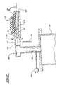
- FIG. 2 is an enlarged cross-sectional view of a kinetic spray nozzle used in the system.
- the present invention comprises an improvement to the kinetic spray process as generally described in U.S. Pat. Nos. 6,139,913, 6,283,386 and the article by Van Steenkiste, et al. entitled “Kinetic Spray Coatings” published in Surface and Coatings Technology Volume III, Pages 62-72, Jan. 10, 1999, all of which are herein incorporated by reference.
- System 10 includes an enclosure 12 in which a support table 14 or other support means is located.
- a mounting panel 16 fixed to the table 14 supports a work holder 18 capable of movement in three dimensions and able to support a suitable workpiece formed of a substrate material to be coated.
- the enclosure 12 includes surrounding walls having at least one air inlet, not shown, and an air outlet 20 connected by a suitable exhaust conduit 22 to a dust collector, not shown.
- the dust collector continually draws air from the enclosure 12 and collects any dust or particles contained in the exhaust air for subsequent disposal.
- the spray system 10 further includes an air compressor 24 capable of supplying air pressure up to 3.4 MPa (500 psi) to a high pressure air ballast tank 26 .
- the air ballast tank 26 is connected through a line 28 to both a low pressure powder feeder 30 and a separate air heater 32 .
- the air heater 32 supplies high pressure heated air, the main gas described below, to a kinetic spray nozzle 34 .
- the pressure of the main gas generally is set at from 150 to 500 psi.
- the low pressure powder feeder 30 mixes particles of a spray powder and supplies the mixture of particles to the nozzle 34 .
- a computer control 35 operates to control both the pressure of air supplied to the air heater 32 and the temperature of the heated main gas exiting the air heater 32 .
- FIG. 2 is a cross-sectional view of the nozzle 34 and its connections to the air heater 32 and the powder feeder 30 .
- a main air passage 36 connects the air heater 32 to the nozzle 34 .
- Passage 36 connects with a premix chamber 38 that directs air through a flow straightener 40 and into a chamber 42 .
- Temperature and pressure of the air or other heated main gas are monitored by a gas inlet temperature thermocouple 44 in the passage 36 and a pressure sensor 46 connected to the chamber 42 .
- the main gas has a temperature that is always insufficient to cause melting in the nozzle 34 of any particles being sprayed.
- the main gas temperature generally ranges from 200 to 3000° F.
- the main gas temperature can be well above the melt temperature of the particles.
- Main gas temperatures that are 5 to 7 fold above the melt temperature of the particles have been used in the present system 10 . What is necessary is that the temperature and exposure time to the main gas be selected such that the particles do not melt in the nozzle 34 .
- the temperature of the gas rapidly falls as it travels through the nozzle 34 .
- the temperature of the gas measured as it exits the nozzle 34 is often at or below room temperature even when its initial temperature is above 1000° F.
- Chamber 42 is in communication with a de Laval type supersonic nozzle 54 .
- the nozzle 54 has a central axis 52 and an entrance cone 56 that decreases in diameter to a throat 58 .
- the entrance cone 56 forms a converging region of the nozzle 54 . Downstream of the throat 58 is an exit end 60 and a diverging region is defined between the throat 58 and the exit end 60 .
- the largest diameter of the entrance cone 56 may range from 10 to 6 millimeters, with 7.5 millimeters being preferred.
- the entrance cone 56 narrows to the throat 58 .
- the throat 58 may have a diameter of from 3.5 to 1.5 millimeters, with from 3 to 2 millimeters being preferred.
- the diverging region of the nozzle 54 from downstream of the throat 58 to the exit end 60 may have a variety of shapes, but in a preferred embodiment it has a rectangular cross-sectional shape.
- the nozzle 54 preferably has a rectangular shape with a long dimension of from 8 to 14 millimeters by a short dimension of from 2 to 6 millimeters.
- the de Laval nozzle 54 is modified from previous systems in the diverging region.
- a mixture of unheated low pressure air and coating powder is fed from the powder feeder 30 through one of a plurality of supplemental inlet lines 48 each of which is connected to a powder injector tube 50 comprising a tube having a predetermined inner diameter.
- the injector tubes 50 supply the particles to the nozzle 54 in the diverging region downstream from the throat 58 , which is a region of reduced pressure.
- the length of the nozzle 54 from the throat 58 to the exit end can vary widely and typically ranges from 100 to 400 millimeters.
- the number of injector tubes 50 , the angle of their entry relative to the central axis 52 and their position downstream from the throat 58 can vary depending on any of a number of parameters. In FIG. 2 ten injector tubes 50 are show, but the number can be as low as one and as high as the available room of the diverging region.
- the angle relative to the central axis 52 can be any that ensures that the particles are directed toward the exit end 60 , basically from 1 to about 90 degrees. It has been found that an angle of 45 degrees relative to central axis 52 works well.
- An inner diameter of the injector tube 50 can vary between 0.4 to 3.0 millimeters. The use of multiple injector tubes 50 permits one to easily modify the system 10 .
- a rapid change over is not easily accomplished with prior systems.
- the system 10 could include a plurality of powder feeders 30 .
- the system also permits one to mix a number of powders in a single injection cycle by having a plurality of powder feeders 30 and injector tubes 50 functioning simultaneously.
- An operator can also run a plurality of particle populations, each having a different average nominal diameter, with the larger population being injected closer to the throat 58 relative to the smaller size particle populations and still get efficient deposition.
- the present system 10 will permit an operator to better optimize the deposition efficiency of a particle or mixture of particles. For example, it is known that harder materials have a higher critical velocity, therefore in a mixture of particles the harder particles could be introduced at a point closer to the throat 58 thereby giving a longer acceleration time.
- a nozzle 54 having a length of 300 millimeters from throat 58 to exit end 60 , a throat of 2 millimeters and an exit end 60 with a rectangular opening of 5 by 12.5 millimeters the pressure drops quickly as one goes downstream from the throat 58 .
- the measured pressures were: 14.5 psi at 1 inch after the throat 58 ; 20 psi at 2 inches from the throat 58 ; 12.8 psi at 3 inches from the throat 58 ; 9.25 psi at 4 inches from the throat 58 ; 10 psi at 5 inches from the throat 58 and below atmospheric pressure beyond 6 inches from the throat 58 .
- the low pressure powder feeder 30 of the present invention has a cost that is approximately ten-fold lower than the high pressure powder feeders that have been used in past systems. Generally, the low pressure powder feeder 30 is used at a pressure of 100 psi or less. All that is required is that it exceed the main gas pressure at the point of injection.
- the nozzle 54 produces an exit velocity of the entrained particles of from 300 meters per second to as high as 1200 meters per second.
- the entrained particles gain kinetic and thermal energy during their flow through this nozzle 54 .
- the main gas temperature is defined as the temperature of heated high-pressure gas at the inlet to the nozzle 54 . Since these temperatures are chosen so that they heat the particles to a temperature that is less than the melting temperature of the particles, even upon impact, there is no change in the solid phase of the original particles due to transfer of kinetic and thermal energy, and therefore no change in their original physical properties.
- the particles themselves are always at a temperature below their melt temperature.
- the particles exiting the nozzle 54 are directed toward a surface of a substrate to coat it.
- the particles Upon striking a substrate opposite the nozzle 54 the particles flatten into a nub-like structure with an aspect ratio of generally about 5 to 1.
- the substrate is a metal and the particles are a metal the particles striking the substrate surface fracture the oxidation on the surface layer and subsequently form a direct metal-to-metal bond between the metal particle and the metal substrate.
- the kinetic sprayed particles transfer substantially all of their kinetic and thermal energy to the substrate surface and stick if their yield stress has been exceeded.
- critical velocity is dependent on the material composition of the particle.
- harder materials must achieve a higher critical velocity before they adhere to a given substrate. It is not known at this time exactly what is the nature of the particle to substrate bond; however, it is believed that a portion of the bond is due to the particles plastically deforming upon striking the substrate.
- the substrate material useful in the present invention may be comprised of any of a wide variety of materials including a metal, an alloy, a semi-conductor, a ceramic, a plastic, and mixtures of these materials. All of these substrates can be coated by the process of the present invention.
- the particles used in the present invention may comprise any of the materials disclosed in U.S. Pat. Nos. 6,139,913 and 6,283,386 in addition to other know particles. These particles generally comprise metals, alloys, ceramics, polymers, diamonds and mixtures of these.
- the particles may have an average nominal diameter of from 1 to 110 microns. Preferably the particles have an average nominal diameter of from 50 to 90 microns.
- a system and nozzle designed according to U.S. Pat. No. 6,139,913 was used to spray tin particles having an average nominal diameter of 60 to 90 microns onto a substrate.
- the substrate was not sandblasted prior to attempts to coat it.
- the nozzle had a length of 80 millimeters from throat to exit end, a throat of 2.8 millimeters, and an injector tube that injected the particles under a high pressure of approximately 300 to 350 psi into the chamber.
- the maximal main gas temperature that could be used without clogging of the nozzle in that system was 300° F.
- a system 10 designed according to the present invention was used.
- the nozzle 54 had a length from throat 58 to exit end of 300 mm with a rectangular exit of 5 by 12.5 millimeters and a throat 58 of 2.8 millimeters.
- a total of eleven injector tubes 50 were positioned into the nozzle 54 after the throat 58 .
- the injector tubes 50 were spaced apart by one inch and set at an angle of 45 degrees with respect to the central axis 52 .
- tin particles of 60 to 90 microns could be sprayed at a main gas temperature of up to 1000° F. without clogging of the nozzle 54 .
- tin particles were sprayed through injector tubes 50 at one, seven and eight inches downstream from the throat 58 .
- the injection pressures ranged from just over positive pressure at both seven and eight inches from the throat to 20 psi at one inch from the throat 58 .
- a powder can be sprayed at over a three-fold higher temperature and a sixteen-fold lower pressure compared to prior kinetic spray systems.
Abstract
Description
- The present invention is directed to a method and nozzle for producing a coating using a kinetic spray system with much lower powder pressures than previously used. The invention permits one to significantly decrease the cost of the powder delivery system, to run the system at higher temperatures for increased deposition efficiency and to eliminate clogging of the nozzle.
- U.S. Pat. No. 6,139,913, “Kinetic Spray Coating Method and Apparatus,” and U.S. Pat. No. 6,283,386 “Kinetic Spray Coating Apparatus” are incorporated by reference herein.
- A new technique for producing coatings on a wide variety of substrate surfaces by kinetic spray, or cold gas dynamic spray, was recently reported in an article by T. H. Van Steenkiste et al., entitled “Kinetic Spray Coatings,” published in Surface and Coatings Technology, vol. 111, pages 6271, Jan. 10, 1999. The article discusses producing continuous layer coatings having low porosity, high adhesion, low oxide content and low thermal stress. The article describes coatings being produced by entraining metal powders in an accelerated air stream, through a converging-diverging de Laval type nozzle and projecting them against a target substrate. The particles are accelerated in the high velocity air stream by the drag effect. The air used can be any of a variety of gases including air or helium. It was found that the particles that formed the coating did not melt or thermally soften prior to impingement onto the substrate. It is theorized that the particles adhere to the substrate when their kinetic energy is converted to a sufficient level of thermal and mechanical deformation. Thus, it is believed that the particle velocity must be high enough to exceed the yield stress of the particle to permit it to adhere when it strikes the substrate. It was found that the deposition efficiency of a given particle mixture was increased as the inlet air temperature was increased. Increasing the inlet air temperature decreases its density and increases its velocity. The velocity varies approximately as the square root of the inlet air temperature. The actual mechanism of bonding of the particles to the substrate surface is not fully known at this time. It is believed that the particles must exceed a critical velocity prior to their being able to bond to the substrate. The critical velocity is dependent on the material of the particle. It is believed that the initial particles to adhere to a metal or alloy substrate have broken the oxide shell on the substrate material permitting subsequent metal to metal bond formation between plastically deformed particles and the substrate. Once an initial layer of particles has been formed on a substrate the subsequent particles both bind to the voids between previously bound particles and also engage in particle to particle bonds. The bonding process is not due to melting of the particles in the air stream because the temperature of the air stream and the time of exposure to the heated air are selected to ensure that the temperature of the particles is always below their melting temperature.
- That work had improved upon earlier work by Alkimov et al. as disclosed in U.S. Pat. No. 5,302,414, issued Apr. 12, 1994. Alkimov et al. disclosed producing dense continuous layer coatings with powder particles having a particle size of from 1 to 50 microns using a supersonic spray.
- The Van Steenkiste article reported on work conducted by the National Center for Manufacturing Sciences (NCMS) to improve on the earlier Alkimov process and apparatus. Van Steenkiste et al. demonstrated that Alkimov's apparatus and process could be modified to produce kinetic spray coatings using particle sizes of greater than 50 microns and up to about 106 microns.
- The modified process and apparatus for producing such larger particle size kinetic spray continuous layer coatings are disclosed in U.S. Pat. Nos. 6,139,913, and 6,283,386. The process and apparatus provide for heating a high pressure air flow up to about 650° C. and combining this with a flow of particles. The heated air and particles are directed through a de Laval-type nozzle to produce a particle exit velocity of between about 300 m/s (meters per second) to about 1000 m/s. The thus accelerated particles are directed toward and impact upon a target substrate with sufficient kinetic energy to impinge the particles to the surface of the substrate. The temperatures and pressures used are lower than that necessary to cause particle melting or thermal softening of the selected particle. Therefore, no phase transition occurs in the particles prior to impingement. It has been found that each type of particle material has a threshold critical velocity that must be exceeded before the material begins to adhere to the substrate. The disclosed method did not disclose the use of particles in excess of 106 microns.
- There are several difficulties associated with current kinetic spray systems. First, the powder is injected into the heated main gas stream prior to passage through the de Laval nozzle. Because the heated main gas stream is under high pressure injection of the powder requires high pressure powder delivery systems, which are quite expensive. Second, the powder particles and heated main gas both must pass through the throat of the nozzle and the particles frequently plug a portion of the diverging section and the nozzle throat, which requires a complete shutdown of the system and cleaning of the nozzle. Finally, for a given material the main gas temperature must be sufficiently low that it does not result in melting of the particles and significant plugging of the nozzle, which may not be an ideal temperature for efficient deposition.
- In one embodiment the present invention is a method of kinetic spray coating a substrate comprising the steps of: providing particles of a material to be sprayed; providing a supersonic nozzle having a throat located between a converging region and a diverging region; directing a flow of a gas through the nozzle, the gas having a temperature insufficient to cause melting of the particles in the nozzle; and injecting the particles directly into the diverging region of the nozzle at a point after the throat, entraining the particles in the flow of the gas and accelerating the particles to a velocity sufficient to result in adherence of the particles on a substrate positioned opposite the nozzle.
- In another embodiment the present invention is a supersonic nozzle for a kinetic spray system comprising: a throat located between a converging region and a diverging region, the diverging region defined between the throat and an exit end; and at least one injector positioned between the throat and the exit end, the injector in direct communication with the diverging region.
- In yet another embodiment the present invention is a kinetic spray system comprising: a supersonic nozzle comprising a throat located between a converging region and a diverging region, the diverging region defined between the throat and an exit end; at least one injector positioned between the throat and the exit end, the injector in direct communication with the diverging region; a low pressure powder feeder connected to the at least one injector; and a high pressure source of a heated main gas connected to the nozzle.
- In the drawings:
- FIG. 1 is a generally schematic layout illustrating a kinetic spray system for performing the method of the present invention; and
- FIG. 2 is an enlarged cross-sectional view of a kinetic spray nozzle used in the system.
- The present invention comprises an improvement to the kinetic spray process as generally described in U.S. Pat. Nos. 6,139,913, 6,283,386 and the article by Van Steenkiste, et al. entitled “Kinetic Spray Coatings” published in Surface and Coatings Technology Volume III, Pages 62-72, Jan. 10, 1999, all of which are herein incorporated by reference.
- Referring first to FIG. 1, a kinetic spray system according to the present invention is generally shown at 10.
System 10 includes anenclosure 12 in which a support table 14 or other support means is located. Amounting panel 16 fixed to the table 14 supports awork holder 18 capable of movement in three dimensions and able to support a suitable workpiece formed of a substrate material to be coated. Theenclosure 12 includes surrounding walls having at least one air inlet, not shown, and anair outlet 20 connected by asuitable exhaust conduit 22 to a dust collector, not shown. During coating operations, the dust collector continually draws air from theenclosure 12 and collects any dust or particles contained in the exhaust air for subsequent disposal. - The
spray system 10 further includes anair compressor 24 capable of supplying air pressure up to 3.4 MPa (500 psi) to a high pressureair ballast tank 26. Theair ballast tank 26 is connected through aline 28 to both a lowpressure powder feeder 30 and aseparate air heater 32. Theair heater 32 supplies high pressure heated air, the main gas described below, to akinetic spray nozzle 34. The pressure of the main gas generally is set at from 150 to 500 psi. The lowpressure powder feeder 30 mixes particles of a spray powder and supplies the mixture of particles to thenozzle 34. Acomputer control 35 operates to control both the pressure of air supplied to theair heater 32 and the temperature of the heated main gas exiting theair heater 32. - FIG. 2 is a cross-sectional view of the
nozzle 34 and its connections to theair heater 32 and thepowder feeder 30. Amain air passage 36 connects theair heater 32 to thenozzle 34.Passage 36 connects with apremix chamber 38 that directs air through aflow straightener 40 and into achamber 42. Temperature and pressure of the air or other heated main gas are monitored by a gasinlet temperature thermocouple 44 in thepassage 36 and apressure sensor 46 connected to thechamber 42. The main gas has a temperature that is always insufficient to cause melting in thenozzle 34 of any particles being sprayed. The main gas temperature generally ranges from 200 to 3000° F. The main gas temperature can be well above the melt temperature of the particles. Main gas temperatures that are 5 to 7 fold above the melt temperature of the particles have been used in thepresent system 10. What is necessary is that the temperature and exposure time to the main gas be selected such that the particles do not melt in thenozzle 34. The temperature of the gas rapidly falls as it travels through thenozzle 34. In fact, the temperature of the gas measured as it exits thenozzle 34 is often at or below room temperature even when its initial temperature is above 1000° F. -
Chamber 42 is in communication with a de Laval typesupersonic nozzle 54. Thenozzle 54 has acentral axis 52 and anentrance cone 56 that decreases in diameter to athroat 58. Theentrance cone 56 forms a converging region of thenozzle 54. Downstream of thethroat 58 is anexit end 60 and a diverging region is defined between thethroat 58 and theexit end 60. The largest diameter of theentrance cone 56 may range from 10 to 6 millimeters, with 7.5 millimeters being preferred. Theentrance cone 56 narrows to thethroat 58. Thethroat 58 may have a diameter of from 3.5 to 1.5 millimeters, with from 3 to 2 millimeters being preferred. The diverging region of thenozzle 54 from downstream of thethroat 58 to theexit end 60 may have a variety of shapes, but in a preferred embodiment it has a rectangular cross-sectional shape. At theexit end 60 thenozzle 54 preferably has a rectangular shape with a long dimension of from 8 to 14 millimeters by a short dimension of from 2 to 6 millimeters. - The de
Laval nozzle 54 is modified from previous systems in the diverging region. In the present invention a mixture of unheated low pressure air and coating powder is fed from thepowder feeder 30 through one of a plurality ofsupplemental inlet lines 48 each of which is connected to apowder injector tube 50 comprising a tube having a predetermined inner diameter. For simplicity the actual connections between thepowder feeder 30 and the inlet lines 48 are not shown. Theinjector tubes 50 supply the particles to thenozzle 54 in the diverging region downstream from thethroat 58, which is a region of reduced pressure. The length of thenozzle 54 from thethroat 58 to the exit end can vary widely and typically ranges from 100 to 400 millimeters. - As would be understood by one of ordinary skill in the art the number of
injector tubes 50, the angle of their entry relative to thecentral axis 52 and their position downstream from thethroat 58 can vary depending on any of a number of parameters. In FIG. 2 teninjector tubes 50 are show, but the number can be as low as one and as high as the available room of the diverging region. The angle relative to thecentral axis 52 can be any that ensures that the particles are directed toward theexit end 60, basically from 1 to about 90 degrees. It has been found that an angle of 45 degrees relative tocentral axis 52 works well. An inner diameter of theinjector tube 50 can vary between 0.4 to 3.0 millimeters. The use ofmultiple injector tubes 50 permits one to easily modify thesystem 10. One can rapidly change particles by turning off afirst powder feeder 30 connected to afirst injector tube 50 and the turning on asecond powder feeder 30 connected to asecond injector tube 50. Such a rapid change over is not easily accomplished with prior systems. For simplicity only onepowder feeder 30 is shown in FIG. 1, however, as would be understood by one of ordinary skill in the art, thesystem 10 could include a plurality ofpowder feeders 30. The system also permits one to mix a number of powders in a single injection cycle by having a plurality ofpowder feeders 30 andinjector tubes 50 functioning simultaneously. An operator can also run a plurality of particle populations, each having a different average nominal diameter, with the larger population being injected closer to thethroat 58 relative to the smaller size particle populations and still get efficient deposition. Thepresent system 10 will permit an operator to better optimize the deposition efficiency of a particle or mixture of particles. For example, it is known that harder materials have a higher critical velocity, therefore in a mixture of particles the harder particles could be introduced at a point closer to thethroat 58 thereby giving a longer acceleration time. - Using a
nozzle 54 having a length of 300 millimeters fromthroat 58 to exitend 60, a throat of 2 millimeters and anexit end 60 with a rectangular opening of 5 by 12.5 millimeters the pressure drops quickly as one goes downstream from thethroat 58. The measured pressures were: 14.5 psi at 1 inch after thethroat 58; 20 psi at 2 inches from thethroat 58; 12.8 psi at 3 inches from thethroat 58; 9.25 psi at 4 inches from thethroat 58; 10 psi at 5 inches from thethroat 58 and below atmospheric pressure beyond 6 inches from thethroat 58. These results show that one can use much lower pressures to inject the powder when the injection takes place after thethroat 58. The lowpressure powder feeder 30 of the present invention has a cost that is approximately ten-fold lower than the high pressure powder feeders that have been used in past systems. Generally, the lowpressure powder feeder 30 is used at a pressure of 100 psi or less. All that is required is that it exceed the main gas pressure at the point of injection. - The
nozzle 54 produces an exit velocity of the entrained particles of from 300 meters per second to as high as 1200 meters per second. The entrained particles gain kinetic and thermal energy during their flow through thisnozzle 54. It will be recognized by those of skill in the art that the temperature of the particles in the gas stream will vary depending on the particle size and the main gas temperature. The main gas temperature is defined as the temperature of heated high-pressure gas at the inlet to thenozzle 54. Since these temperatures are chosen so that they heat the particles to a temperature that is less than the melting temperature of the particles, even upon impact, there is no change in the solid phase of the original particles due to transfer of kinetic and thermal energy, and therefore no change in their original physical properties. The particles themselves are always at a temperature below their melt temperature. The particles exiting thenozzle 54 are directed toward a surface of a substrate to coat it. - Upon striking a substrate opposite the
nozzle 54 the particles flatten into a nub-like structure with an aspect ratio of generally about 5 to 1. When the substrate is a metal and the particles are a metal the particles striking the substrate surface fracture the oxidation on the surface layer and subsequently form a direct metal-to-metal bond between the metal particle and the metal substrate. Upon impact the kinetic sprayed particles transfer substantially all of their kinetic and thermal energy to the substrate surface and stick if their yield stress has been exceeded. As discussed above, for a given particle to adhere to a substrate it is necessary that it reach or exceed its critical velocity which is defined as the velocity where at it will adhere to a substrate when it strikes the substrate after exiting thenozzle 54. This critical velocity is dependent on the material composition of the particle. In general, harder materials must achieve a higher critical velocity before they adhere to a given substrate. It is not known at this time exactly what is the nature of the particle to substrate bond; however, it is believed that a portion of the bond is due to the particles plastically deforming upon striking the substrate. - As disclosed in U.S. Pat. No. 6,139,913 the substrate material useful in the present invention may be comprised of any of a wide variety of materials including a metal, an alloy, a semi-conductor, a ceramic, a plastic, and mixtures of these materials. All of these substrates can be coated by the process of the present invention. The particles used in the present invention may comprise any of the materials disclosed in U.S. Pat. Nos. 6,139,913 and 6,283,386 in addition to other know particles. These particles generally comprise metals, alloys, ceramics, polymers, diamonds and mixtures of these. The particles may have an average nominal diameter of from 1 to 110 microns. Preferably the particles have an average nominal diameter of from 50 to 90 microns.
- In a first example a system and nozzle designed according to U.S. Pat. No. 6,139,913 was used to spray tin particles having an average nominal diameter of 60 to 90 microns onto a substrate. The substrate was not sandblasted prior to attempts to coat it. The nozzle had a length of 80 millimeters from throat to exit end, a throat of 2.8 millimeters, and an injector tube that injected the particles under a high pressure of approximately 300 to 350 psi into the chamber. The maximal main gas temperature that could be used without clogging of the nozzle in that system was 300° F.
- In a second series of examples a
system 10 designed according to the present invention was used. Thenozzle 54 had a length fromthroat 58 to exit end of 300 mm with a rectangular exit of 5 by 12.5 millimeters and athroat 58 of 2.8 millimeters. A total of eleveninjector tubes 50 were positioned into thenozzle 54 after thethroat 58. Theinjector tubes 50 were spaced apart by one inch and set at an angle of 45 degrees with respect to thecentral axis 52. Using thisnozzle 54 tin particles of 60 to 90 microns could be sprayed at a main gas temperature of up to 1000° F. without clogging of thenozzle 54. In separate experiments the tin particles were sprayed throughinjector tubes 50 at one, seven and eight inches downstream from thethroat 58. The injection pressures ranged from just over positive pressure at both seven and eight inches from the throat to 20 psi at one inch from thethroat 58. Thus, using thenozzle 54 of the present invention a powder can be sprayed at over a three-fold higher temperature and a sixteen-fold lower pressure compared to prior kinetic spray systems. - While the preferred embodiment of the present invention has been described so as to enable one skilled in the art to practice the present invention, it is to be understood that variations and modifications may be employed without departing from the concept and intent of the present invention as defined in the following claims. The preceding description is intended to be exemplary and should not be used to limit the scope of the invention. The scope of the invention should be determined only by reference to the following claims.
Claims (41)
Priority Applications (1)
| Application Number | Priority Date | Filing Date | Title |
|---|---|---|---|
| US10/117,385 US6811812B2 (en) | 2002-04-05 | 2002-04-05 | Low pressure powder injection method and system for a kinetic spray process |
Applications Claiming Priority (1)
| Application Number | Priority Date | Filing Date | Title |
|---|---|---|---|
| US10/117,385 US6811812B2 (en) | 2002-04-05 | 2002-04-05 | Low pressure powder injection method and system for a kinetic spray process |
Publications (2)
| Publication Number | Publication Date |
|---|---|
| US20030190414A1 true US20030190414A1 (en) | 2003-10-09 |
| US6811812B2 US6811812B2 (en) | 2004-11-02 |
Family
ID=28674185
Family Applications (1)
| Application Number | Title | Priority Date | Filing Date |
|---|---|---|---|
| US10/117,385 Expired - Lifetime US6811812B2 (en) | 2002-04-05 | 2002-04-05 | Low pressure powder injection method and system for a kinetic spray process |
Country Status (1)
| Country | Link |
|---|---|
| US (1) | US6811812B2 (en) |
Cited By (33)
| Publication number | Priority date | Publication date | Assignee | Title |
|---|---|---|---|---|
| US20030190413A1 (en) * | 2002-04-05 | 2003-10-09 | Van Steenkiste Thomas Hubert | Method of maintaining a non-obstructed interior opening in kinetic spray nozzles |
| US20040065432A1 (en) * | 2002-10-02 | 2004-04-08 | Smith John R. | High performance thermal stack for electrical components |
| US20040065391A1 (en) * | 2002-10-02 | 2004-04-08 | Smith John R | Direct application of catalysts to substrates via a thermal spray process for treatment of the atmosphere |
| US20040072008A1 (en) * | 2001-10-09 | 2004-04-15 | Delphi Technologies, Inc. | Kinetic sprayed electrical contacts on conductive substrates |
| US20040101620A1 (en) * | 2002-11-22 | 2004-05-27 | Elmoursi Alaa A. | Method for aluminum metalization of ceramics for power electronics applications |
| US20040142198A1 (en) * | 2003-01-21 | 2004-07-22 | Thomas Hubert Van Steenkiste | Magnetostrictive/magnetic material for use in torque sensors |
| EP1445033A1 (en) * | 2003-02-07 | 2004-08-11 | Delphi Technologies, Inc. | Kinetic spray tin coating method |
| US20050040260A1 (en) * | 2003-08-21 | 2005-02-24 | Zhibo Zhao | Coaxial low pressure injection method and a gas collimator for a kinetic spray nozzle |
| US6871553B2 (en) | 2003-03-28 | 2005-03-29 | Delphi Technologies, Inc. | Integrating fluxgate for magnetostrictive torque sensors |
| US20050074560A1 (en) * | 2003-10-02 | 2005-04-07 | Fuller Brian K. | Correcting defective kinetically sprayed surfaces |
| US20050100489A1 (en) * | 2003-10-30 | 2005-05-12 | Steenkiste Thomas H.V. | Method for securing ceramic structures and forming electrical connections on the same |
| US20050160834A1 (en) * | 2004-01-23 | 2005-07-28 | Nehl Thomas W. | Assembly for measuring movement of and a torque applied to a shaft |
| US20050161532A1 (en) * | 2004-01-23 | 2005-07-28 | Steenkiste Thomas H.V. | Modified high efficiency kinetic spray nozzle |
| US6949300B2 (en) | 2001-08-15 | 2005-09-27 | Delphi Technologies, Inc. | Product and method of brazing using kinetic sprayed coatings |
| US20050211799A1 (en) * | 2004-03-24 | 2005-09-29 | Van Steenkiste Thomas H | Kinetic spray nozzle design for small spot coatings and narrow width structures |
| EP1629899A1 (en) * | 2004-08-23 | 2006-03-01 | Delphi Technologies, Inc. | Replaceable throat insert for a kinetic spray nozzle |
| WO2007137599A1 (en) * | 2006-05-26 | 2007-12-06 | Airbus Deutschland Gmbh | Method for repairing a damaged outer skin region on an aircraft |
| EP1883716A1 (en) * | 2005-04-07 | 2008-02-06 | SNT Co., Ltd. | Method of preparing wear-resistant coating layer comprising metal matrix composite and coating layer prepared thereby |
| US7476422B2 (en) | 2002-05-23 | 2009-01-13 | Delphi Technologies, Inc. | Copper circuit formed by kinetic spray |
| US7589473B2 (en) | 2007-08-06 | 2009-09-15 | Plasma Surgical Investments, Ltd. | Pulsed plasma device and method for generating pulsed plasma |
| US20090256010A1 (en) * | 2008-04-14 | 2009-10-15 | Honeywell International Inc. | Cold gas-dynamic spray nozzle |
| US20100193600A1 (en) * | 2007-07-05 | 2010-08-05 | Osvaldo Di Loreto | Method and Device for Spraying a Pulverulent Material Into a Carrier Gas |
| EP2289630A1 (en) * | 2009-08-27 | 2011-03-02 | General Electric Company | Apparatus and process for depositing coatings |
| US7928338B2 (en) | 2007-02-02 | 2011-04-19 | Plasma Surgical Investments Ltd. | Plasma spraying device and method |
| US8105325B2 (en) | 2005-07-08 | 2012-01-31 | Plasma Surgical Investments Limited | Plasma-generating device, plasma surgical device, use of a plasma-generating device and method of generating a plasma |
| US8109928B2 (en) | 2005-07-08 | 2012-02-07 | Plasma Surgical Investments Limited | Plasma-generating device, plasma surgical device and use of plasma surgical device |
| US8613742B2 (en) | 2010-01-29 | 2013-12-24 | Plasma Surgical Investments Limited | Methods of sealing vessels using plasma |
| US8735766B2 (en) | 2007-08-06 | 2014-05-27 | Plasma Surgical Investments Limited | Cathode assembly and method for pulsed plasma generation |
| US9089319B2 (en) | 2010-07-22 | 2015-07-28 | Plasma Surgical Investments Limited | Volumetrically oscillating plasma flows |
| US9913358B2 (en) | 2005-07-08 | 2018-03-06 | Plasma Surgical Investments Limited | Plasma-generating device, plasma surgical device and use of a plasma surgical device |
| US20180156758A1 (en) * | 2016-12-05 | 2018-06-07 | Battelle Memorial Institute | Magnetostrictive cold spray coating for enhanced ultrasonic inspection |
| US10245615B2 (en) * | 2010-07-15 | 2019-04-02 | Commonwealth Scientific And Industrial Research Organisation | Surface treatment |
| US11882643B2 (en) | 2020-08-28 | 2024-01-23 | Plasma Surgical, Inc. | Systems, methods, and devices for generating predominantly radially expanded plasma flow |
Families Citing this family (18)
| Publication number | Priority date | Publication date | Assignee | Title |
|---|---|---|---|---|
| JP2006229881A (en) * | 2005-02-21 | 2006-08-31 | Toshiba Corp | Key management system and key management method |
| US7717703B2 (en) * | 2005-02-25 | 2010-05-18 | Technical Engineering, Llc | Combustion head for use with a flame spray apparatus |
| KR100802329B1 (en) * | 2005-04-15 | 2008-02-13 | 주식회사 솔믹스 | Method of preparing metal matrix composite and coating layer and bulk prepared by using the same |
| US20070052193A1 (en) * | 2005-09-08 | 2007-03-08 | Meritor Suspension Systems Company, U.S. | Suspension member retention feature |
| CN100446870C (en) * | 2005-10-31 | 2008-12-31 | 宝山钢铁股份有限公司 | Cold air dynamical spray-painting method and apparatus of delivering powder through down stream |
| US20070110919A1 (en) * | 2005-11-15 | 2007-05-17 | ATG Advanced Technology Group s.r.o. | Method for producing photocatalytically active polymers |
| US8132740B2 (en) * | 2006-01-10 | 2012-03-13 | Tessonics Corporation | Gas dynamic spray gun |
| US20100119707A1 (en) * | 2006-02-28 | 2010-05-13 | Honeywell International, Inc. | Protective coatings and coating methods for polymeric materials and composites |
| US20100019058A1 (en) * | 2006-09-13 | 2010-01-28 | Vanderzwet Daniel P | Nozzle assembly for cold gas dynamic spray system |
| US8162239B2 (en) * | 2007-05-21 | 2012-04-24 | Thomas Francis Hursen | Air gun safety nozzle |
| CN101116849B (en) * | 2007-07-31 | 2010-05-19 | 中国船舶重工集团公司第七二五研究所 | De-Laval-Type nozzle for cold spraying |
| US8758849B2 (en) * | 2007-08-06 | 2014-06-24 | Francis C. Dlubak | Method of depositing electrically conductive material onto a substrate |
| US8171659B2 (en) * | 2007-12-10 | 2012-05-08 | Thomas Francis Hursen | Method and apparatus for selective soil fracturing, soil excavation or soil treatment using supersonic pneumatic nozzle with integral fluidized material injector |
| US20090317544A1 (en) * | 2008-05-15 | 2009-12-24 | Zao "Intermetcomposit" | Method and Device for Gasodynamically Marking a Surface with a Mark |
| KR101029582B1 (en) * | 2008-09-19 | 2011-04-15 | (주)엔티시 | powder feeding and coating apparatus with low pressure spray nozzle |
| US9168546B2 (en) * | 2008-12-12 | 2015-10-27 | National Research Council Of Canada | Cold gas dynamic spray apparatus, system and method |
| WO2011094224A1 (en) * | 2010-01-26 | 2011-08-04 | Sulzer Metco (Us), Inc. | Plume shroud for laminar plasma guns |
| JP6438848B2 (en) * | 2015-06-09 | 2018-12-19 | 株式会社スギノマシン | nozzle |
Citations (10)
| Publication number | Priority date | Publication date | Assignee | Title |
|---|---|---|---|---|
| US2861900A (en) * | 1955-05-02 | 1958-11-25 | Union Carbide Corp | Jet plating of high melting point materials |
| US4416421A (en) * | 1980-10-09 | 1983-11-22 | Browning Engineering Corporation | Highly concentrated supersonic liquified material flame spray method and apparatus |
| US5217746A (en) * | 1990-12-13 | 1993-06-08 | Fisher-Barton Inc. | Method for minimizing decarburization and other high temperature oxygen reactions in a plasma sprayed material |
| US5302414A (en) * | 1990-05-19 | 1994-04-12 | Anatoly Nikiforovich Papyrin | Gas-dynamic spraying method for applying a coating |
| US5362523A (en) * | 1991-09-05 | 1994-11-08 | Technalum Research, Inc. | Method for the production of compositionally graded coatings by plasma spraying powders |
| US6139913A (en) * | 1999-06-29 | 2000-10-31 | National Center For Manufacturing Sciences | Kinetic spray coating method and apparatus |
| US6402050B1 (en) * | 1996-11-13 | 2002-06-11 | Alexandr Ivanovich Kashirin | Apparatus for gas-dynamic coating |
| US20020071906A1 (en) * | 2000-12-13 | 2002-06-13 | Rusch William P. | Method and device for applying a coating |
| US20020102360A1 (en) * | 2001-01-30 | 2002-08-01 | Siemens Westinghouse Power Corporation | Thermal barrier coating applied with cold spray technique |
| US6623796B1 (en) * | 2002-04-05 | 2003-09-23 | Delphi Technologies, Inc. | Method of producing a coating using a kinetic spray process with large particles and nozzles for the same |
Family Cites Families (31)
| Publication number | Priority date | Publication date | Assignee | Title |
|---|---|---|---|---|
| US3100724A (en) | 1958-09-22 | 1963-08-13 | Microseal Products Inc | Device for treating the surface of a workpiece |
| US3993411A (en) | 1973-06-01 | 1976-11-23 | General Electric Company | Bonds between metal and a non-metallic substrate |
| US4263335A (en) | 1978-07-26 | 1981-04-21 | Ppg Industries, Inc. | Airless spray method for depositing electroconductive tin oxide coatings |
| US4891275A (en) | 1982-10-29 | 1990-01-02 | Norsk Hydro A.S. | Aluminum shapes coated with brazing material and process of coating |
| US4606495A (en) | 1983-12-22 | 1986-08-19 | United Technologies Corporation | Uniform braze application process |
| US4939022A (en) | 1988-04-04 | 1990-07-03 | Delco Electronics Corporation | Electrical conductors |
| US5187021A (en) | 1989-02-08 | 1993-02-16 | Diamond Fiber Composites, Inc. | Coated and whiskered fibers for use in composite materials |
| US5271965A (en) | 1991-01-16 | 1993-12-21 | Browning James A | Thermal spray method utilizing in-transit powder particle temperatures below their melting point |
| US5476725A (en) | 1991-03-18 | 1995-12-19 | Aluminum Company Of America | Clad metallurgical products and methods of manufacture |
| US5340015A (en) | 1993-03-22 | 1994-08-23 | Westinghouse Electric Corp. | Method for applying brazing filler metals |
| US5527627A (en) | 1993-03-29 | 1996-06-18 | Delco Electronics Corp. | Ink composition for an ultra-thick thick film for thermal management of a hybrid circuit |
| US5395679A (en) | 1993-03-29 | 1995-03-07 | Delco Electronics Corp. | Ultra-thick thick films for thermal management and current carrying capabilities in hybrid circuits |
| JPH07314177A (en) | 1994-03-28 | 1995-12-05 | Mitsubishi Alum Co Ltd | Composition for brazing as well as al material and heat exchanger provided with composition for brazing |
| GB9419328D0 (en) | 1994-09-24 | 1994-11-09 | Sprayform Tools & Dies Ltd | Method for controlling the internal stresses in spray deposited articles |
| US5464146A (en) | 1994-09-29 | 1995-11-07 | Ford Motor Company | Thin film brazing of aluminum shapes |
| US5424101A (en) | 1994-10-24 | 1995-06-13 | General Motors Corporation | Method of making metallized epoxy tools |
| US5593740A (en) | 1995-01-17 | 1997-01-14 | Synmatix Corporation | Method and apparatus for making carbon-encapsulated ultrafine metal particles |
| US5795626A (en) | 1995-04-28 | 1998-08-18 | Innovative Technology Inc. | Coating or ablation applicator with a debris recovery attachment |
| US5744254A (en) | 1995-05-24 | 1998-04-28 | Virginia Tech Intellectual Properties, Inc. | Composite materials including metallic matrix composite reinforcements |
| US6051045A (en) | 1996-01-16 | 2000-04-18 | Ford Global Technologies, Inc. | Metal-matrix composites |
| DE19605858A1 (en) | 1996-02-16 | 1997-08-21 | Claussen Nils | Process for the production of Al¶2¶O¶3¶ aluminide composites, their execution and use |
| GB2310866A (en) | 1996-03-05 | 1997-09-10 | Sprayforming Dev Ltd | Filling porosity or voids in articles formed by spray deposition |
| US6129948A (en) | 1996-12-23 | 2000-10-10 | National Center For Manufacturing Sciences | Surface modification to achieve improved electrical conductivity |
| US5894054A (en) | 1997-01-09 | 1999-04-13 | Ford Motor Company | Aluminum components coated with zinc-antimony alloy for manufacturing assemblies by CAB brazing |
| US5989310A (en) | 1997-11-25 | 1999-11-23 | Aluminum Company Of America | Method of forming ceramic particles in-situ in metal |
| US6033622A (en) | 1998-09-21 | 2000-03-07 | The United States Of America As Represented By The Secretary Of The Air Force | Method for making metal matrix composites |
| DE19959515A1 (en) | 1999-12-09 | 2001-06-13 | Dacs Dvorak Advanced Coating S | Process for plastic coating by means of a spraying process, a device therefor and the use of the layer |
| US6503575B1 (en) | 2000-05-22 | 2003-01-07 | Praxair S.T. Technology, Inc. | Process for producing graded coated articles |
| DE10037212A1 (en) | 2000-07-07 | 2002-01-17 | Linde Gas Ag | Plastic surfaces with a thermally sprayed coating and process for their production |
| RU2183695C2 (en) | 2000-08-25 | 2002-06-20 | Общество С Ограниченной Ответственностью Обнинский Центр Порошкового Напыления | Method of applying coatings |
| DE10126100A1 (en) | 2001-05-29 | 2002-12-05 | Linde Ag | Production of a coating or a molded part comprises injecting powdered particles in a gas stream only in the divergent section of a Laval nozzle, and applying the particles at a specified speed |
-
2002
- 2002-04-05 US US10/117,385 patent/US6811812B2/en not_active Expired - Lifetime
Patent Citations (11)
| Publication number | Priority date | Publication date | Assignee | Title |
|---|---|---|---|---|
| US2861900A (en) * | 1955-05-02 | 1958-11-25 | Union Carbide Corp | Jet plating of high melting point materials |
| US4416421A (en) * | 1980-10-09 | 1983-11-22 | Browning Engineering Corporation | Highly concentrated supersonic liquified material flame spray method and apparatus |
| US5302414A (en) * | 1990-05-19 | 1994-04-12 | Anatoly Nikiforovich Papyrin | Gas-dynamic spraying method for applying a coating |
| US5302414B1 (en) * | 1990-05-19 | 1997-02-25 | Anatoly N Papyrin | Gas-dynamic spraying method for applying a coating |
| US5217746A (en) * | 1990-12-13 | 1993-06-08 | Fisher-Barton Inc. | Method for minimizing decarburization and other high temperature oxygen reactions in a plasma sprayed material |
| US5362523A (en) * | 1991-09-05 | 1994-11-08 | Technalum Research, Inc. | Method for the production of compositionally graded coatings by plasma spraying powders |
| US6402050B1 (en) * | 1996-11-13 | 2002-06-11 | Alexandr Ivanovich Kashirin | Apparatus for gas-dynamic coating |
| US6139913A (en) * | 1999-06-29 | 2000-10-31 | National Center For Manufacturing Sciences | Kinetic spray coating method and apparatus |
| US20020071906A1 (en) * | 2000-12-13 | 2002-06-13 | Rusch William P. | Method and device for applying a coating |
| US20020102360A1 (en) * | 2001-01-30 | 2002-08-01 | Siemens Westinghouse Power Corporation | Thermal barrier coating applied with cold spray technique |
| US6623796B1 (en) * | 2002-04-05 | 2003-09-23 | Delphi Technologies, Inc. | Method of producing a coating using a kinetic spray process with large particles and nozzles for the same |
Cited By (55)
| Publication number | Priority date | Publication date | Assignee | Title |
|---|---|---|---|---|
| US6949300B2 (en) | 2001-08-15 | 2005-09-27 | Delphi Technologies, Inc. | Product and method of brazing using kinetic sprayed coatings |
| US20040072008A1 (en) * | 2001-10-09 | 2004-04-15 | Delphi Technologies, Inc. | Kinetic sprayed electrical contacts on conductive substrates |
| US7001671B2 (en) | 2001-10-09 | 2006-02-21 | Delphi Technologies, Inc. | Kinetic sprayed electrical contacts on conductive substrates |
| US6896933B2 (en) | 2002-04-05 | 2005-05-24 | Delphi Technologies, Inc. | Method of maintaining a non-obstructed interior opening in kinetic spray nozzles |
| US20030190413A1 (en) * | 2002-04-05 | 2003-10-09 | Van Steenkiste Thomas Hubert | Method of maintaining a non-obstructed interior opening in kinetic spray nozzles |
| US7476422B2 (en) | 2002-05-23 | 2009-01-13 | Delphi Technologies, Inc. | Copper circuit formed by kinetic spray |
| US20040065432A1 (en) * | 2002-10-02 | 2004-04-08 | Smith John R. | High performance thermal stack for electrical components |
| US20040065391A1 (en) * | 2002-10-02 | 2004-04-08 | Smith John R | Direct application of catalysts to substrates via a thermal spray process for treatment of the atmosphere |
| US6924249B2 (en) | 2002-10-02 | 2005-08-02 | Delphi Technologies, Inc. | Direct application of catalysts to substrates via a thermal spray process for treatment of the atmosphere |
| US20040101620A1 (en) * | 2002-11-22 | 2004-05-27 | Elmoursi Alaa A. | Method for aluminum metalization of ceramics for power electronics applications |
| US20040142198A1 (en) * | 2003-01-21 | 2004-07-22 | Thomas Hubert Van Steenkiste | Magnetostrictive/magnetic material for use in torque sensors |
| US20040157000A1 (en) * | 2003-02-07 | 2004-08-12 | Steenkiste Thomas Hubert Van | Method for producing electrical contacts using selective melting and a low pressure kinetic spray process |
| EP1445033A1 (en) * | 2003-02-07 | 2004-08-11 | Delphi Technologies, Inc. | Kinetic spray tin coating method |
| US6872427B2 (en) * | 2003-02-07 | 2005-03-29 | Delphi Technologies, Inc. | Method for producing electrical contacts using selective melting and a low pressure kinetic spray process |
| US20050103126A1 (en) * | 2003-03-28 | 2005-05-19 | Delphi Technologies, Inc. | Integrating fluxgate for magnetostrictive torque sensors |
| US6871553B2 (en) | 2003-03-28 | 2005-03-29 | Delphi Technologies, Inc. | Integrating fluxgate for magnetostrictive torque sensors |
| US20050040260A1 (en) * | 2003-08-21 | 2005-02-24 | Zhibo Zhao | Coaxial low pressure injection method and a gas collimator for a kinetic spray nozzle |
| US20050074560A1 (en) * | 2003-10-02 | 2005-04-07 | Fuller Brian K. | Correcting defective kinetically sprayed surfaces |
| US7351450B2 (en) | 2003-10-02 | 2008-04-01 | Delphi Technologies, Inc. | Correcting defective kinetically sprayed surfaces |
| US20050100489A1 (en) * | 2003-10-30 | 2005-05-12 | Steenkiste Thomas H.V. | Method for securing ceramic structures and forming electrical connections on the same |
| US7335341B2 (en) | 2003-10-30 | 2008-02-26 | Delphi Technologies, Inc. | Method for securing ceramic structures and forming electrical connections on the same |
| US20050161532A1 (en) * | 2004-01-23 | 2005-07-28 | Steenkiste Thomas H.V. | Modified high efficiency kinetic spray nozzle |
| US7024946B2 (en) | 2004-01-23 | 2006-04-11 | Delphi Technologies, Inc. | Assembly for measuring movement of and a torque applied to a shaft |
| US7475831B2 (en) | 2004-01-23 | 2009-01-13 | Delphi Technologies, Inc. | Modified high efficiency kinetic spray nozzle |
| US20050160834A1 (en) * | 2004-01-23 | 2005-07-28 | Nehl Thomas W. | Assembly for measuring movement of and a torque applied to a shaft |
| US7244466B2 (en) * | 2004-03-24 | 2007-07-17 | Delphi Technologies, Inc. | Kinetic spray nozzle design for small spot coatings and narrow width structures |
| US20050211799A1 (en) * | 2004-03-24 | 2005-09-29 | Van Steenkiste Thomas H | Kinetic spray nozzle design for small spot coatings and narrow width structures |
| KR100767251B1 (en) * | 2004-08-23 | 2007-10-17 | 델피 테크놀로지스 인코포레이티드 | Replaceable throat insert for a kinetic spray nozzle |
| EP1629899A1 (en) * | 2004-08-23 | 2006-03-01 | Delphi Technologies, Inc. | Replaceable throat insert for a kinetic spray nozzle |
| EP1883716A1 (en) * | 2005-04-07 | 2008-02-06 | SNT Co., Ltd. | Method of preparing wear-resistant coating layer comprising metal matrix composite and coating layer prepared thereby |
| EP1883716A4 (en) * | 2005-04-07 | 2009-07-29 | Snt Co Ltd | Method of preparing wear-resistant coating layer comprising metal matrix composite and coating layer prepared thereby |
| US8109928B2 (en) | 2005-07-08 | 2012-02-07 | Plasma Surgical Investments Limited | Plasma-generating device, plasma surgical device and use of plasma surgical device |
| US9913358B2 (en) | 2005-07-08 | 2018-03-06 | Plasma Surgical Investments Limited | Plasma-generating device, plasma surgical device and use of a plasma surgical device |
| US10201067B2 (en) | 2005-07-08 | 2019-02-05 | Plasma Surgical Investments Limited | Plasma-generating device, plasma surgical device and use of a plasma surgical device |
| US8105325B2 (en) | 2005-07-08 | 2012-01-31 | Plasma Surgical Investments Limited | Plasma-generating device, plasma surgical device, use of a plasma-generating device and method of generating a plasma |
| US20090130327A1 (en) * | 2006-05-26 | 2009-05-21 | Airbus Deutschland Gmbh | Method for Repairing a Damaged Outer Skin Region on an Aircraft |
| WO2007137599A1 (en) * | 2006-05-26 | 2007-12-06 | Airbus Deutschland Gmbh | Method for repairing a damaged outer skin region on an aircraft |
| US7928338B2 (en) | 2007-02-02 | 2011-04-19 | Plasma Surgical Investments Ltd. | Plasma spraying device and method |
| US8408479B2 (en) * | 2007-07-05 | 2013-04-02 | Fib-Services Intellectual S.A. | Method and device for spraying a pulverulent material into a carrier gas |
| US20100193600A1 (en) * | 2007-07-05 | 2010-08-05 | Osvaldo Di Loreto | Method and Device for Spraying a Pulverulent Material Into a Carrier Gas |
| CN101755070B (en) * | 2007-07-05 | 2012-12-05 | Fib环球服务股份公司 | Method and device for spraying a pulverulent material into a carrier gas |
| US7589473B2 (en) | 2007-08-06 | 2009-09-15 | Plasma Surgical Investments, Ltd. | Pulsed plasma device and method for generating pulsed plasma |
| US8030849B2 (en) | 2007-08-06 | 2011-10-04 | Plasma Surgical Investments Limited | Pulsed plasma device and method for generating pulsed plasma |
| US8735766B2 (en) | 2007-08-06 | 2014-05-27 | Plasma Surgical Investments Limited | Cathode assembly and method for pulsed plasma generation |
| US20090256010A1 (en) * | 2008-04-14 | 2009-10-15 | Honeywell International Inc. | Cold gas-dynamic spray nozzle |
| EP2289630A1 (en) * | 2009-08-27 | 2011-03-02 | General Electric Company | Apparatus and process for depositing coatings |
| JP2011045877A (en) * | 2009-08-27 | 2011-03-10 | General Electric Co <Ge> | Apparatus and method for depositing coating |
| US8613742B2 (en) | 2010-01-29 | 2013-12-24 | Plasma Surgical Investments Limited | Methods of sealing vessels using plasma |
| US10245615B2 (en) * | 2010-07-15 | 2019-04-02 | Commonwealth Scientific And Industrial Research Organisation | Surface treatment |
| US9089319B2 (en) | 2010-07-22 | 2015-07-28 | Plasma Surgical Investments Limited | Volumetrically oscillating plasma flows |
| US10463418B2 (en) | 2010-07-22 | 2019-11-05 | Plasma Surgical Investments Limited | Volumetrically oscillating plasma flows |
| US10492845B2 (en) | 2010-07-22 | 2019-12-03 | Plasma Surgical Investments Limited | Volumetrically oscillating plasma flows |
| US10631911B2 (en) | 2010-07-22 | 2020-04-28 | Plasma Surgical Investments Limited | Volumetrically oscillating plasma flows |
| US20180156758A1 (en) * | 2016-12-05 | 2018-06-07 | Battelle Memorial Institute | Magnetostrictive cold spray coating for enhanced ultrasonic inspection |
| US11882643B2 (en) | 2020-08-28 | 2024-01-23 | Plasma Surgical, Inc. | Systems, methods, and devices for generating predominantly radially expanded plasma flow |
Also Published As
| Publication number | Publication date |
|---|---|
| US6811812B2 (en) | 2004-11-02 |
Similar Documents
| Publication | Publication Date | Title |
|---|---|---|
| US6811812B2 (en) | Low pressure powder injection method and system for a kinetic spray process | |
| US6623796B1 (en) | Method of producing a coating using a kinetic spray process with large particles and nozzles for the same | |
| US6743468B2 (en) | Method of coating with combined kinetic spray and thermal spray | |
| US7108893B2 (en) | Spray system with combined kinetic spray and thermal spray ability | |
| EP1200200B2 (en) | Kinetic spray coating method and apparatus | |
| EP1579921A2 (en) | Improved kinetic spray nozzle system design | |
| US20060038044A1 (en) | Replaceable throat insert for a kinetic spray nozzle | |
| EP1630253A1 (en) | Continuous in-line manufacturing process for high speed coating deposition via kinetic spray process | |
| WO2005072249A2 (en) | A modified high efficiency kinetic spray nozzle | |
| US6808817B2 (en) | Kinetically sprayed aluminum metal matrix composites for thermal management | |
| EP1775026B1 (en) | Improved non-clogging powder injector for a kinetic spray nozzle system | |
| US6872427B2 (en) | Method for producing electrical contacts using selective melting and a low pressure kinetic spray process | |
| EP1508379B1 (en) | Gas collimator for a kinetic powder spray nozzle | |
| US7244466B2 (en) | Kinetic spray nozzle design for small spot coatings and narrow width structures | |
| US7335341B2 (en) | Method for securing ceramic structures and forming electrical connections on the same | |
| US7351450B2 (en) | Correcting defective kinetically sprayed surfaces |
Legal Events
| Date | Code | Title | Description |
|---|---|---|---|
| AS | Assignment |
Owner name: DELPHI TECHNOLOGIES, INC., MICHIGAN Free format text: ASSIGNMENT OF ASSIGNORS INTEREST;ASSIGNOR:VAN STEENKISTE, THOMAS HUBERT;REEL/FRAME:012781/0484 Effective date: 20020215 |
|
| STCF | Information on status: patent grant |
Free format text: PATENTED CASE |
|
| REMI | Maintenance fee reminder mailed | ||
| FPAY | Fee payment |
Year of fee payment: 4 |
|
| SULP | Surcharge for late payment | ||
| AS | Assignment |
Owner name: F.W. GARTNER THERMAL SPRAYING, LTD., TEXAS Free format text: ASSIGNMENT OF ASSIGNORS INTEREST;ASSIGNOR:DELPHI TECHNOLOGIES, INC.;REEL/FRAME:022793/0494 Effective date: 20090422 Owner name: F.W. GARTNER THERMAL SPRAYING, LTD.,TEXAS Free format text: ASSIGNMENT OF ASSIGNORS INTEREST;ASSIGNOR:DELPHI TECHNOLOGIES, INC.;REEL/FRAME:022793/0494 Effective date: 20090422 |
|
| FEPP | Fee payment procedure |
Free format text: PAT HOLDER CLAIMS SMALL ENTITY STATUS, ENTITY STATUS SET TO SMALL (ORIGINAL EVENT CODE: LTOS); ENTITY STATUS OF PATENT OWNER: SMALL ENTITY |
|
| AS | Assignment |
Owner name: FLAME-SPRAY INDUSTRIES, INC., NEW YORK Free format text: ASSIGNMENT OF ASSIGNORS INTEREST;ASSIGNOR:F.W. GARTNER THERMAL SPRAYING, LTD.;REEL/FRAME:027902/0906 Effective date: 20120312 |
|
| FPAY | Fee payment |
Year of fee payment: 8 |
|
| REMI | Maintenance fee reminder mailed | ||
| FPAY | Fee payment |
Year of fee payment: 12 |
|
| SULP | Surcharge for late payment |
Year of fee payment: 11 |