US20030190415A1 - Method of producing a coating using a kinetic spray process with large particles and nozzles for the same - Google Patents
Method of producing a coating using a kinetic spray process with large particles and nozzles for the same Download PDFInfo
- Publication number
- US20030190415A1 US20030190415A1 US10/117,704 US11770402A US2003190415A1 US 20030190415 A1 US20030190415 A1 US 20030190415A1 US 11770402 A US11770402 A US 11770402A US 2003190415 A1 US2003190415 A1 US 2003190415A1
- Authority
- US
- United States
- Prior art keywords
- particles
- gas
- millimeters
- flow
- nozzle
- Prior art date
- Legal status (The legal status is an assumption and is not a legal conclusion. Google has not performed a legal analysis and makes no representation as to the accuracy of the status listed.)
- Granted
Links
Images


Classifications
-
- C—CHEMISTRY; METALLURGY
- C23—COATING METALLIC MATERIAL; COATING MATERIAL WITH METALLIC MATERIAL; CHEMICAL SURFACE TREATMENT; DIFFUSION TREATMENT OF METALLIC MATERIAL; COATING BY VACUUM EVAPORATION, BY SPUTTERING, BY ION IMPLANTATION OR BY CHEMICAL VAPOUR DEPOSITION, IN GENERAL; INHIBITING CORROSION OF METALLIC MATERIAL OR INCRUSTATION IN GENERAL
- C23C—COATING METALLIC MATERIAL; COATING MATERIAL WITH METALLIC MATERIAL; SURFACE TREATMENT OF METALLIC MATERIAL BY DIFFUSION INTO THE SURFACE, BY CHEMICAL CONVERSION OR SUBSTITUTION; COATING BY VACUUM EVAPORATION, BY SPUTTERING, BY ION IMPLANTATION OR BY CHEMICAL VAPOUR DEPOSITION, IN GENERAL
- C23C24/00—Coating starting from inorganic powder
- C23C24/02—Coating starting from inorganic powder by application of pressure only
- C23C24/04—Impact or kinetic deposition of particles
-
- B—PERFORMING OPERATIONS; TRANSPORTING
- B05—SPRAYING OR ATOMISING IN GENERAL; APPLYING FLUENT MATERIALS TO SURFACES, IN GENERAL
- B05B—SPRAYING APPARATUS; ATOMISING APPARATUS; NOZZLES
- B05B7/00—Spraying apparatus for discharge of liquids or other fluent materials from two or more sources, e.g. of liquid and air, of powder and gas
- B05B7/14—Spraying apparatus for discharge of liquids or other fluent materials from two or more sources, e.g. of liquid and air, of powder and gas designed for spraying particulate materials
- B05B7/1481—Spray pistols or apparatus for discharging particulate material
- B05B7/1486—Spray pistols or apparatus for discharging particulate material for spraying particulate material in dry state
-
- B—PERFORMING OPERATIONS; TRANSPORTING
- B05—SPRAYING OR ATOMISING IN GENERAL; APPLYING FLUENT MATERIALS TO SURFACES, IN GENERAL
- B05D—PROCESSES FOR APPLYING FLUENT MATERIALS TO SURFACES, IN GENERAL
- B05D1/00—Processes for applying liquids or other fluent materials
- B05D1/02—Processes for applying liquids or other fluent materials performed by spraying
- B05D1/08—Flame spraying
- B05D1/10—Applying particulate materials
-
- B—PERFORMING OPERATIONS; TRANSPORTING
- B05—SPRAYING OR ATOMISING IN GENERAL; APPLYING FLUENT MATERIALS TO SURFACES, IN GENERAL
- B05D—PROCESSES FOR APPLYING FLUENT MATERIALS TO SURFACES, IN GENERAL
- B05D1/00—Processes for applying liquids or other fluent materials
- B05D1/02—Processes for applying liquids or other fluent materials performed by spraying
- B05D1/12—Applying particulate materials
-
- B—PERFORMING OPERATIONS; TRANSPORTING
- B05—SPRAYING OR ATOMISING IN GENERAL; APPLYING FLUENT MATERIALS TO SURFACES, IN GENERAL
- B05B—SPRAYING APPARATUS; ATOMISING APPARATUS; NOZZLES
- B05B7/00—Spraying apparatus for discharge of liquids or other fluent materials from two or more sources, e.g. of liquid and air, of powder and gas
- B05B7/16—Spraying apparatus for discharge of liquids or other fluent materials from two or more sources, e.g. of liquid and air, of powder and gas incorporating means for heating or cooling the material to be sprayed
- B05B7/1606—Spraying apparatus for discharge of liquids or other fluent materials from two or more sources, e.g. of liquid and air, of powder and gas incorporating means for heating or cooling the material to be sprayed the spraying of the material involving the use of an atomising fluid, e.g. air
- B05B7/1613—Spraying apparatus for discharge of liquids or other fluent materials from two or more sources, e.g. of liquid and air, of powder and gas incorporating means for heating or cooling the material to be sprayed the spraying of the material involving the use of an atomising fluid, e.g. air comprising means for heating the atomising fluid before mixing with the material to be sprayed
Definitions
- the present invention is directed to a method for producing a coating using a kinetic spray system with much larger particles than previously used.
- the invention further includes a kinetic spray nozzle for use with the larger particles.
- the invention permits one to increase the particle size used in the system up to at least 250 microns, thereby increasing the range of useful particles and decreasing the processing difficulties associated with the smaller particles typically used.
- the air used can be any of a variety of gases including air or helium. It was found that the particles that formed the coating did not melt or thermally soften prior to impingement onto the substrate. It is theorized that the particles adhere to the substrate when their kinetic energy is converted to a sufficient level of thermal and mechanical deformation. Thus, it is believed that the particle velocity must be high enough to exceed the yield stress of the particle to permit it to adhere when it strikes the substrate. It was found that the deposition efficiency of a given particle mixture was increased as the inlet air temperature was increased. Increasing the inlet air temperature decreases its density and increases its velocity. The velocity varies approximately as the square root of the inlet air temperature. The actual mechanism of bonding of the particles to the substrate surface is not fully known at this time.
- the particles must exceed a critical velocity prior to their being able to bond to the substrate.
- the critical velocity is dependent on the material of the particle. It is believed that the initial particles to adhere to a substrate have broken the oxide shell on the substrate material permitting subsequent metal to metal bond formation between plastically deformed particles and the substrate. Once an initial layer of particles has been formed on a substrate subsequent particles bind not only to the voids between previous particles bound to the substrate but also engage in particle to particle bonds. The bonding process is not due to melting of the particles in the air stream because the temperature of the air stream is always below the melting temperature of the particles and the temperature of the particles is always below that of the air stream.
- Alkimov et al. disclosed producing dense continuous layer coatings with powder particles having a particle size of from 1 to 50 microns using a supersonic spray.
- Van Steenkiste article reported on work conducted by the National Center for Manufacturing Sciences (NCMS) to improve on the earlier Alkimov process and apparatus. Van Steenkiste et al. demonstrated that Alkimov's apparatus and process could be modified to produce kinetic spray coatings using particle sizes of greater than 50 microns and up to about 106 microns.
- This modified process and apparatus for producing such larger particle size kinetic spray continuous layer coatings are disclosed in U.S. Pat. Nos. 6,139,913, and 6,283,386.
- the process and apparatus provide for heating a high pressure air flow up to about 650° C. and combining this with a flow of particles.
- the heated air and particles are directed through a de Laval-type nozzle to produce a particle exit velocity of between about 300 m/s (meters per second) to about 1000 m/s.
- the thus accelerated particles are directed toward and impact upon a target substrate with sufficient kinetic energy to impinge the particles to the surface of the substrate.
- the temperatures and pressures used are sufficiently lower than that necessary to cause particle melting or thermal softening of the selected particle.
- the present invention is a method of kinetic spray coating a substrate comprising the steps of: providing particles having an average nominal diameter equal to or less than 250 microns; entraining the particles into a flow of a gas, the gas at a temperature below a melt temperature of the particles; and directing the particles entrained in the flow of gas through a supersonic nozzle having a length from a throat to an exit end of from 200 to 400 millimeters thereby accelerating the particles to a velocity sufficient to result in adherence of the particles on a substrate positioned opposite the nozzle.
- the present invention is a method of kinetic spray coating a substrate comprising the steps of: providing particles having an average nominal diameter equal to or less than 250 microns; passing the particles through a powder injector tube having an inner diameter equal to or less than 0.90 millimeters and into a flow of a gas; entraining the particles into the flow of the gas, the gas at a temperature below a melt temperature of the particles; and directing the particles entrained in the flow of gas through a supersonic nozzle having a length from a throat to an exit end of from 200 to 400 millimeters thereby accelerating the particles to a velocity sufficient to result in adherence of the particles on a substrate positioned opposite the nozzle.
- FIG. 1 is a generally schematic layout illustrating a kinetic spray system for performing the method of the present invention.
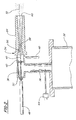
- FIG. 2 is an enlarged cross-sectional view of a kinetic spray nozzle used in the system.
- the present invention comprises an improvement to the kinetic spray process as generally described in U.S. Pat. Nos. 6,139,913, 6,283,386 and the article by Van Steenkiste, et al. entitled “Kinetic Spray Coatings” published in Surface and Coatings Technology Volume III, Pages 62-72, Jan. 10, 1999, all of which are herein incorporated by reference.
- System 10 includes an enclosure 12 in which a support table 14 or other support means is located.
- a mounting panel 16 fixed to the table 14 supports a work holder 18 capable of movement in three dimensions and able to support a suitable workpiece formed of a substrate material to be coated.
- the enclosure 12 includes surrounding walls having at least one air inlet, not shown, and an air outlet 20 connected by a suitable exhaust conduit 22 to a dust collector, not shown.
- the dust collector continually draws air from the enclosure 12 and collects any dust or particles contained in the exhaust air for subsequent disposal.
- the spray system 10 further includes an air compressor 24 capable of supplying air pressure up to 3.4 MPa (500 psi) to a high pressure air ballast tank 26 .
- the air ballast tank 26 is connected through a line 28 to both a high pressure powder feeder 30 and a separate air heater 32 .
- the air heater 32 supplies high pressure heated air, the main gas described below, to a kinetic spray nozzle 34 .
- the powder feeder 30 mixes particles of a spray powder with unheated high pressure air and supplies the mixture to a supplemental inlet line 48 of the nozzle 34 .
- a computer control 35 operates to control both the pressure of air supplied to the air heater 32 and the temperature of the heated main gas exiting the air heater 32 .
- FIG. 2 is a cross-sectional view of the nozzle 34 and its connections to the air heater 32 and the supplemental inlet line 48 .
- a main air passage 36 connects the air heater 32 to the nozzle 34 .
- Passage 36 connects with a premix chamber 38 which directs air through a flow straightener 40 and into a mixing chamber 42 .
- Temperature and pressure of the air or other heated main gas are monitored by a gas inlet temperature thermocouple 44 in the passage 36 and a pressure sensor 46 connected to the mixing chamber 42 .
- the mixture of unheated high pressure air and coating powder is fed through the supplemental inlet line 48 to a powder injector tube 50 comprising a straight pipe having a predetermined inner diameter.
- the tube 50 has a central axis 52 which is preferentially the same as the axis of the premix chamber 38 .
- the tube 50 extends through the premix chamber 38 and the flow straightener 40 into the mixing chamber 42 .
- Mixing chamber 42 is in communication with the de Laval type nozzle 54 .
- the nozzle 54 has an entrance cone 56 that decreases in diameter to a throat 58 . Downstream of the throat is an exit end 60 .
- the largest diameter of the entrance cone 56 may range from 10 to 6 millimeters, with 7.5 millimeters being preferred.
- the entrance cone 56 narrows to the throat 58 .
- the throat 58 may have a diameter of from 3.5 to 1.5 millimeters, with from 3 to 2 millimeters being preferred.
- the portion of the nozzle 54 from downstream of the throat 58 to the exit end 60 may have a variety of shapes, but in a preferred embodiment it has a rectangular cross-sectional shape.
- the nozzle 54 preferably has a rectangular shape with a long dimension of from 8 to 14 millimeters by a short dimension of from 2 to 6 millimeters.
- the powder injector tube 50 supplies a particle powder mixture to the system 10 under a pressure in excess of the pressure of the heated main gas from the passage 36 .
- the nozzle 54 produces an exit velocity of the entrained particles of from 300 meters per second to as high as 1200 meters per second. The entrained particles gain kinetic and thermal energy during their flow through this nozzle. It will be recognized by those of skill in the art that the temperature of the particles in the gas stream will vary depending on the particle size and the main gas temperature.
- the main gas temperature is defined as the temperature of heated high-pressure gas at the inlet to the nozzle 54 .
- the particles are always at a temperature below the main gas temperature.
- the particles exiting the nozzle 54 are directed toward a surface of a substrate to coat it.
- the particles Upon striking a substrate opposite the nozzle 54 the particles flatten into a nub-like structure with an aspect ratio of generally about 5 to 1.
- the substrate is a metal and the particles are a metal the particles striking the substrate surface fracture the oxidation on the surface layer and subsequently form a direct metal-to-metal bond between the metal particle and the metal substrate.
- the kinetic sprayed particles transfer substantially all of their kinetic and thermal energy to the substrate surface and stick if their yield stress has been exceeded.
- critical velocity is defined as the velocity where at it will adhere to a substrate when it strikes the substrate after exiting the nozzle. This critical velocity is dependent on the material composition of the particle.
- harder materials must achieve a higher critical velocity before they adhere to a given substrate. It is not known at this time exactly what is the nature of the particle to substrate bond; however, it is believed that a portion of the bond is due to the particles plastically deforming upon striking the substrate.
- the substrate material may be comprised of any of a wide variety of materials including a metal, an alloy, a semi-conductor, a ceramic, a plastic, and mixtures of these materials. All of these substrates can be coated by the process of the present invention.
- the particles used in the present invention may comprise any of the materials disclosed in U.S. Pat. Nos. 6,139,913 and 6,283,386 in addition to other know particles. These particles generally comprise metals, alloys, ceramics, polymers, diamonds and mixtures of these.
- present kinetic spray systems generally utilize particles of 106 microns or less. Larger particles do not adhere to the substrates in current systems.
- the present invention discloses a method for using much larger particles than previous systems. In fact, the present invention discloses use of particle in the range of up to 250 microns. This is accomplished by making two modifications to present kinetic spray systems.
- the inner diameter of the powder injector tube 50 which directs the powder into the de Laval nozzle 54 , is reduced to a size of from 0.90 millimeter to 0.40 millimeter. This is in contrast to a typical system wherein the powder injector tube generally has an inner diameter of approximately 2.45 millimeters or larger. This is believed to provide two important benefits that allow for spraying of larger particles.
- the smaller diameter reduces the amount of unheated air that is combined with the heated main gas in the mixing chamber 42 and thereby leads to a smaller reduction in the main gas temperature. The higher the main gas temperature the faster a given particle is accelerated over a given distance.
- the size of the inner diameter of the injector tube 50 can be reduced down to the size of the particles one is injecting, however, in general it is preferably from 0.90 to 0.40 millimeters in diameter.
- the length of the nozzle 54 from the throat 58 to the exit end 60 is greatly increased.
- the length of the nozzle 54 from the throat 58 to the exit end 60 is from 60 to 80 millimeters.
- the length has been increased to from 200 to 400 millimeters.
- This increase in length in combination with the smaller injector tube 50 inner diameter allows one to spray particles up to 250 microns in diameter.
- the longer nozzle 54 allows one to keep the main gas temperature below the melting temperature of many useful materials and to use very large particles of these materials.
- the present invention extends the size of usable powders to ones up to 250 microns in diameter. The longer length enables the main gas to accelerate the larger particles to velocities upon exit of from 300 to 1200 m/s.
- the system 10 was use to spray copper particles having an average nominal diameter of 250 microns onto an aluminum substrate.
- the substrate was not sandblasted prior to attempts to coat it.
- a nozzle 54 having a length of 80 millimeters from throat 58 to exit end 60 , a throat 58 of 2 millimeters, and an injector tube 50 inner diameter of 0.89, the particles could not be adhered to the substrate.
- the system 10 was changed to a nozzle 54 having a length of 300 millimeters from the 2 millimeter throat 58 to the exit end 60 the particles adhered very well to the substrate.
- the nozzle 54 had a rectangular cross-sectional area beyond the throat 58 and an exit size of 5 by 12.5 millimeters.
- the main gas temperature was set at 1200° F. and its pressure was 300 psi.
- the powder feed parameters were: 70° F., 350 psi and 500 rpm on the feeder.
Abstract
A method of depositing large particles having an average nominal diameter of up to 250 microns onto substrates using a kinetic spray system is disclosed. The method utilizes a powder injector tube having a reduced inner diameter and a de Laval type nozzle having an elongated throat to exit end length. The method permits deposition of much larger particles than previously possible.
Description
- U.S. Pat. No. 6,139,913, “Kinetic Spray Coating Method and Apparatus,” and U.S. Pat. No. 6,283,386 “Kinetic Spray Coating Apparatus” are incorporated by reference herein.
- The present invention is directed to a method for producing a coating using a kinetic spray system with much larger particles than previously used. The invention further includes a kinetic spray nozzle for use with the larger particles. The invention permits one to increase the particle size used in the system up to at least 250 microns, thereby increasing the range of useful particles and decreasing the processing difficulties associated with the smaller particles typically used.
- A new technique for producing coatings on a wide variety of substrate surfaces by kinetic spray, or cold gas dynamic spray, was recently reported in an article by T. H. Van Steenkiste et al., entitled “Kinetic Spray Coatings,” published in Surface and Coatings Technology, vol. 111, pages 62-71, Jan. 10, 1999. The article discusses producing continuous layer coatings having low porosity, high adhesion, low oxide content and low thermal stress. The article describes coatings being produced by entraining metal powders in an accelerated air stream, through a converging-diverging de Laval type nozzle and projecting them against a target substrate. The particles are accelerated in the high velocity air stream by the drag effect. The air used can be any of a variety of gases including air or helium. It was found that the particles that formed the coating did not melt or thermally soften prior to impingement onto the substrate. It is theorized that the particles adhere to the substrate when their kinetic energy is converted to a sufficient level of thermal and mechanical deformation. Thus, it is believed that the particle velocity must be high enough to exceed the yield stress of the particle to permit it to adhere when it strikes the substrate. It was found that the deposition efficiency of a given particle mixture was increased as the inlet air temperature was increased. Increasing the inlet air temperature decreases its density and increases its velocity. The velocity varies approximately as the square root of the inlet air temperature. The actual mechanism of bonding of the particles to the substrate surface is not fully known at this time. It is believed that the particles must exceed a critical velocity prior to their being able to bond to the substrate. The critical velocity is dependent on the material of the particle. It is believed that the initial particles to adhere to a substrate have broken the oxide shell on the substrate material permitting subsequent metal to metal bond formation between plastically deformed particles and the substrate. Once an initial layer of particles has been formed on a substrate subsequent particles bind not only to the voids between previous particles bound to the substrate but also engage in particle to particle bonds. The bonding process is not due to melting of the particles in the air stream because the temperature of the air stream is always below the melting temperature of the particles and the temperature of the particles is always below that of the air stream.
- This work improved upon earlier work by Alkimov et al. as disclosed in U.S. Pat. No. 5,302,414, issued Apr. 12, 1994. Alkimov et al. disclosed producing dense continuous layer coatings with powder particles having a particle size of from 1 to 50 microns using a supersonic spray.
- The Van Steenkiste article reported on work conducted by the National Center for Manufacturing Sciences (NCMS) to improve on the earlier Alkimov process and apparatus. Van Steenkiste et al. demonstrated that Alkimov's apparatus and process could be modified to produce kinetic spray coatings using particle sizes of greater than 50 microns and up to about 106 microns.
- This modified process and apparatus for producing such larger particle size kinetic spray continuous layer coatings are disclosed in U.S. Pat. Nos. 6,139,913, and 6,283,386. The process and apparatus provide for heating a high pressure air flow up to about 650° C. and combining this with a flow of particles. The heated air and particles are directed through a de Laval-type nozzle to produce a particle exit velocity of between about 300 m/s (meters per second) to about 1000 m/s. The thus accelerated particles are directed toward and impact upon a target substrate with sufficient kinetic energy to impinge the particles to the surface of the substrate. The temperatures and pressures used are sufficiently lower than that necessary to cause particle melting or thermal softening of the selected particle. Therefore, no phase transition occurs in the particles prior to impingement. It has been found that each type of particle material has a threshold critical velocity that must be exceeded before the material begins to adhere to the substrate. The disclosed method did not disclose the use of particles in excess of 106 microns.
- One difficulty associated with all of these prior art kinetic spray systems arises from the small size of the particles that are used. The largest particles are 106 microns, and more typically the particles range from 10 to 50 microns. Because of their large surface to volume ratio these particles tend to have a higher level of oxide formation which is detrimental to the process. It is also difficult to handle these small particles in the feed systems, because they tend to clog the systems. Thus it would be very beneficial to develop a process that could use larger particles to reduce these problems.
- In a first embodiment the present invention is a method of kinetic spray coating a substrate comprising the steps of: providing particles having an average nominal diameter equal to or less than 250 microns; entraining the particles into a flow of a gas, the gas at a temperature below a melt temperature of the particles; and directing the particles entrained in the flow of gas through a supersonic nozzle having a length from a throat to an exit end of from 200 to 400 millimeters thereby accelerating the particles to a velocity sufficient to result in adherence of the particles on a substrate positioned opposite the nozzle.
- In a second embodiment the present invention is a method of kinetic spray coating a substrate comprising the steps of: providing particles having an average nominal diameter equal to or less than 250 microns; passing the particles through a powder injector tube having an inner diameter equal to or less than 0.90 millimeters and into a flow of a gas; entraining the particles into the flow of the gas, the gas at a temperature below a melt temperature of the particles; and directing the particles entrained in the flow of gas through a supersonic nozzle having a length from a throat to an exit end of from 200 to 400 millimeters thereby accelerating the particles to a velocity sufficient to result in adherence of the particles on a substrate positioned opposite the nozzle.
- In the drawings:
- FIG. 1 is a generally schematic layout illustrating a kinetic spray system for performing the method of the present invention; and
- FIG. 2 is an enlarged cross-sectional view of a kinetic spray nozzle used in the system.
- The present invention comprises an improvement to the kinetic spray process as generally described in U.S. Pat. Nos. 6,139,913, 6,283,386 and the article by Van Steenkiste, et al. entitled “Kinetic Spray Coatings” published in Surface and Coatings Technology Volume III, Pages 62-72, Jan. 10, 1999, all of which are herein incorporated by reference.
- Referring first to FIG. 1, a kinetic spray system according to the present invention is generally shown at 10.
System 10 includes anenclosure 12 in which a support table 14 or other support means is located. Amounting panel 16 fixed to the table 14 supports awork holder 18 capable of movement in three dimensions and able to support a suitable workpiece formed of a substrate material to be coated. Theenclosure 12 includes surrounding walls having at least one air inlet, not shown, and anair outlet 20 connected by asuitable exhaust conduit 22 to a dust collector, not shown. During coating operations, the dust collector continually draws air from theenclosure 12 and collects any dust or particles contained in the exhaust air for subsequent disposal. - The
spray system 10 further includes anair compressor 24 capable of supplying air pressure up to 3.4 MPa (500 psi) to a high pressureair ballast tank 26. Theair ballast tank 26 is connected through aline 28 to both a highpressure powder feeder 30 and aseparate air heater 32. Theair heater 32 supplies high pressure heated air, the main gas described below, to akinetic spray nozzle 34. Thepowder feeder 30 mixes particles of a spray powder with unheated high pressure air and supplies the mixture to asupplemental inlet line 48 of thenozzle 34. Acomputer control 35 operates to control both the pressure of air supplied to theair heater 32 and the temperature of the heated main gas exiting theair heater 32. - FIG. 2 is a cross-sectional view of the
nozzle 34 and its connections to theair heater 32 and thesupplemental inlet line 48. Amain air passage 36 connects theair heater 32 to thenozzle 34.Passage 36 connects with apremix chamber 38 which directs air through aflow straightener 40 and into a mixingchamber 42. Temperature and pressure of the air or other heated main gas are monitored by a gasinlet temperature thermocouple 44 in thepassage 36 and apressure sensor 46 connected to the mixingchamber 42. - The mixture of unheated high pressure air and coating powder is fed through the
supplemental inlet line 48 to apowder injector tube 50 comprising a straight pipe having a predetermined inner diameter. Thetube 50 has acentral axis 52 which is preferentially the same as the axis of thepremix chamber 38. Thetube 50 extends through thepremix chamber 38 and theflow straightener 40 into the mixingchamber 42. - Mixing
chamber 42 is in communication with the deLaval type nozzle 54. Thenozzle 54 has anentrance cone 56 that decreases in diameter to athroat 58. Downstream of the throat is anexit end 60. The largest diameter of theentrance cone 56 may range from 10 to 6 millimeters, with 7.5 millimeters being preferred. Theentrance cone 56 narrows to thethroat 58. Thethroat 58 may have a diameter of from 3.5 to 1.5 millimeters, with from 3 to 2 millimeters being preferred. The portion of thenozzle 54 from downstream of thethroat 58 to theexit end 60 may have a variety of shapes, but in a preferred embodiment it has a rectangular cross-sectional shape. At theexit end 60 thenozzle 54 preferably has a rectangular shape with a long dimension of from 8 to 14 millimeters by a short dimension of from 2 to 6 millimeters. - As disclosed in U.S. Pat. Nos. 6,139,913 and 6,283,386 the
powder injector tube 50 supplies a particle powder mixture to thesystem 10 under a pressure in excess of the pressure of the heated main gas from thepassage 36. Thenozzle 54 produces an exit velocity of the entrained particles of from 300 meters per second to as high as 1200 meters per second. The entrained particles gain kinetic and thermal energy during their flow through this nozzle. It will be recognized by those of skill in the art that the temperature of the particles in the gas stream will vary depending on the particle size and the main gas temperature. The main gas temperature is defined as the temperature of heated high-pressure gas at the inlet to thenozzle 54. Since these temperatures are substantially less than the melting point of the particles, even upon impact, there is no change in the solid phase of the original particles due to transfer of kinetic and thermal energy, and therefore no change in their original physical properties. The particles are always at a temperature below the main gas temperature. The particles exiting thenozzle 54 are directed toward a surface of a substrate to coat it. - Upon striking a substrate opposite the
nozzle 54 the particles flatten into a nub-like structure with an aspect ratio of generally about 5 to 1. When the substrate is a metal and the particles are a metal the particles striking the substrate surface fracture the oxidation on the surface layer and subsequently form a direct metal-to-metal bond between the metal particle and the metal substrate. Upon impact the kinetic sprayed particles transfer substantially all of their kinetic and thermal energy to the substrate surface and stick if their yield stress has been exceeded. As discussed above, for a given particle to adhere to a substrate it is necessary that it reach or exceed its critical velocity which is defined as the velocity where at it will adhere to a substrate when it strikes the substrate after exiting the nozzle. This critical velocity is dependent on the material composition of the particle. In general, harder materials must achieve a higher critical velocity before they adhere to a given substrate. It is not known at this time exactly what is the nature of the particle to substrate bond; however, it is believed that a portion of the bond is due to the particles plastically deforming upon striking the substrate. - As disclosed in U.S. Pat. No. 6,139,913 the substrate material may be comprised of any of a wide variety of materials including a metal, an alloy, a semi-conductor, a ceramic, a plastic, and mixtures of these materials. All of these substrates can be coated by the process of the present invention. The particles used in the present invention may comprise any of the materials disclosed in U.S. Pat. Nos. 6,139,913 and 6,283,386 in addition to other know particles. These particles generally comprise metals, alloys, ceramics, polymers, diamonds and mixtures of these.
- As discussed above, present kinetic spray systems generally utilize particles of 106 microns or less. Larger particles do not adhere to the substrates in current systems. The present invention discloses a method for using much larger particles than previous systems. In fact, the present invention discloses use of particle in the range of up to 250 microns. This is accomplished by making two modifications to present kinetic spray systems.
- First, the inner diameter of the
powder injector tube 50, which directs the powder into the deLaval nozzle 54, is reduced to a size of from 0.90 millimeter to 0.40 millimeter. This is in contrast to a typical system wherein the powder injector tube generally has an inner diameter of approximately 2.45 millimeters or larger. This is believed to provide two important benefits that allow for spraying of larger particles. The smaller diameter reduces the amount of unheated air that is combined with the heated main gas in the mixingchamber 42 and thereby leads to a smaller reduction in the main gas temperature. The higher the main gas temperature the faster a given particle is accelerated over a given distance. In addition, the smaller the inner diameter of theinjector tube 50 the less turbulence it introduces in the flow of the gas through thenozzle 54. Turbulence is detrimental to acceleration of particles in thenozzle 54. As a theoretical limit the size of the inner diameter of theinjector tube 50 can be reduced down to the size of the particles one is injecting, however, in general it is preferably from 0.90 to 0.40 millimeters in diameter. - Second, the length of the
nozzle 54 from thethroat 58 to theexit end 60 is greatly increased. In a typical system the length of thenozzle 54 from thethroat 58 to theexit end 60 is from 60 to 80 millimeters. In the present invention the length has been increased to from 200 to 400 millimeters. This increase in length in combination with thesmaller injector tube 50 inner diameter allows one to spray particles up to 250 microns in diameter. Thelonger nozzle 54 allows one to keep the main gas temperature below the melting temperature of many useful materials and to use very large particles of these materials. In general, the present invention extends the size of usable powders to ones up to 250 microns in diameter. The longer length enables the main gas to accelerate the larger particles to velocities upon exit of from 300 to 1200 m/s. - In a first example the
system 10 was use to spray copper particles having an average nominal diameter of 250 microns onto an aluminum substrate. The substrate was not sandblasted prior to attempts to coat it. Using anozzle 54 having a length of 80 millimeters fromthroat 58 to exitend 60, athroat 58 of 2 millimeters, and aninjector tube 50 inner diameter of 0.89, the particles could not be adhered to the substrate. When thesystem 10 was changed to anozzle 54 having a length of 300 millimeters from the 2millimeter throat 58 to theexit end 60 the particles adhered very well to the substrate. Thenozzle 54 had a rectangular cross-sectional area beyond thethroat 58 and an exit size of 5 by 12.5 millimeters. In both experiments the main gas temperature was set at 1200° F. and its pressure was 300 psi. The powder feed parameters were: 70° F., 350 psi and 500 rpm on the feeder. - While the preferred embodiment of the present invention has been described so as to enable one skilled in the art to practice the present invention, it is to be understood that variations and modifications may be employed without departing from the concept and intent of the present invention as defined in the following claims. The preceding description is intended to be exemplary and should not be used to limit the scope of the invention. The scope of the invention should be determined only by reference to the following claims.
Claims (20)
1. A method of kinetic spray coating a substrate comprising the steps of:
a) providing particles having an average nominal diameter equal to or less than 250 microns;
b) entraining the particles into a flow of a gas, the gas at a temperature below a melt temperature of the particles; and
c) directing the particles entrained in the flow of gas through a supersonic nozzle having a length from a throat to an exit end of from 200 to 400 millimeters, thereby accelerating the particles to a velocity sufficient to result in adherence of the particles on a substrate positioned opposite the nozzle.
2. The method of claim 1 , wherein step a) comprises providing particles having an average nominal diameter of from 125 to 250 microns.
3. The method of claim 1 , wherein step a) comprises providing particles comprising at least one of a metal, an alloy, a polymer, a ceramic, a diamond, or mixtures thereof.
4. The method of claim 1 , wherein step b) further comprises setting the gas at a temperature of from 300 to 3000° F.
5. The method of claim 4 , wherein the gas is set at a temperature of from 300 to 1500° F.
6. The method of claim 1 , further comprising directing the particles entrained in the flow of gas through a supersonic nozzle having a throat diameter of from 3.5 to 1.5 millimeters.
7. The method of claim 1 , further comprising directing the particles entrained in the flow of gas through a supersonic nozzle having a throat diameter of from 3.0 to 2.0 millimeters.
8. The method of claim 1 , wherein step c) comprises directing the particles entrained in the flow of gas through a supersonic nozzle having a length from the throat to the exit end of from 250 to 350 millimeters.
9. The method of claim 1 , further comprising the step of directing the particles of step a) through an injector tube having an inner diameter of from 0.40 to 0.90 millimeters and then entraining the particles into the flow of gas in step b).
10. The method of claim 1 , wherein step c) further comprises positioning a substrate comprising at least one of a metal, an alloy, a ceramic, a plastic, or a mixture thereof opposite the nozzle.
11. A method of kinetic spray coating a substrate comprising the steps of:
a) providing particles having an average nominal diameter equal to or less than 250 microns;
b) passing the particles through a powder injector tube having an inner diameter equal to or less than 0.90 millimeters and into a flow of a gas;
c) entraining the particles into the flow of the gas, the gas at a temperature below a melt temperature of the particles; and
d) directing the particles entrained in the flow of gas through a supersonic nozzle having a length from a throat to an exit end of from 200 to 400 millimeters thereby accelerating the particles to a velocity sufficient to result in adherence of the particles on a substrate positioned opposite the nozzle.
12. The method of claim 11 , wherein step a) comprises providing particles having an average nominal diameter of from 125 to 250 microns.
13. The method of claim 11 , wherein step a) comprises providing particles comprising at least one of a metal, an alloy, a polymer, a ceramic, a diamond, or mixtures thereof.
14. The method of claim 11 , wherein step b) further comprises setting the gas at a temperature of from 300 to 3000° F.
15. The method of claim 14 , wherein the gas is set at a temperature of from 300 to 1500° F.
16. The method of claim 11 , further comprising directing the particles entrained in the flow of gas through a supersonic nozzle having a throat diameter of from 3.5 to 1.5 millimeters.
17. The method of claim 11 , further comprising directing the particles entrained in the flow of gas through a supersonic nozzle having a throat diameter of from 3.0 to 2.0 millimeters.
18. The method of claim 11 , wherein step d) comprises directing the particles entrained in the flow of gas through a supersonic nozzle having a length from the throat to the exit end of from 250 to 350 millimeters.
19. The method of claim 11 , wherein step b) comprises passing the particles of step a) through a powder injector tube having an inner diameter of from 0.40 to 0.90 millimeters.
20. The method of claim 11 , wherein step d) further comprises positioning a substrate comprising at least one of a metal, an alloy, a ceramic, a plastic, or a mixture thereof opposite the nozzle.
Priority Applications (1)
| Application Number | Priority Date | Filing Date | Title |
|---|---|---|---|
| US10/117,704 US6623796B1 (en) | 2002-04-05 | 2002-04-05 | Method of producing a coating using a kinetic spray process with large particles and nozzles for the same |
Applications Claiming Priority (1)
| Application Number | Priority Date | Filing Date | Title |
|---|---|---|---|
| US10/117,704 US6623796B1 (en) | 2002-04-05 | 2002-04-05 | Method of producing a coating using a kinetic spray process with large particles and nozzles for the same |
Publications (2)
| Publication Number | Publication Date |
|---|---|
| US6623796B1 US6623796B1 (en) | 2003-09-23 |
| US20030190415A1 true US20030190415A1 (en) | 2003-10-09 |
Family
ID=28041109
Family Applications (1)
| Application Number | Title | Priority Date | Filing Date |
|---|---|---|---|
| US10/117,704 Expired - Fee Related US6623796B1 (en) | 2002-04-05 | 2002-04-05 | Method of producing a coating using a kinetic spray process with large particles and nozzles for the same |
Country Status (1)
| Country | Link |
|---|---|
| US (1) | US6623796B1 (en) |
Cited By (2)
| Publication number | Priority date | Publication date | Assignee | Title |
|---|---|---|---|---|
| US20060040048A1 (en) * | 2004-08-23 | 2006-02-23 | Taeyoung Han | Continuous in-line manufacturing process for high speed coating deposition via a kinetic spray process |
| US10245615B2 (en) * | 2010-07-15 | 2019-04-02 | Commonwealth Scientific And Industrial Research Organisation | Surface treatment |
Families Citing this family (48)
| Publication number | Priority date | Publication date | Assignee | Title |
|---|---|---|---|---|
| US20030039856A1 (en) * | 2001-08-15 | 2003-02-27 | Gillispie Bryan A. | Product and method of brazing using kinetic sprayed coatings |
| US6685988B2 (en) * | 2001-10-09 | 2004-02-03 | Delphi Technologies, Inc. | Kinetic sprayed electrical contacts on conductive substrates |
| US6811812B2 (en) * | 2002-04-05 | 2004-11-02 | Delphi Technologies, Inc. | Low pressure powder injection method and system for a kinetic spray process |
| US6896933B2 (en) * | 2002-04-05 | 2005-05-24 | Delphi Technologies, Inc. | Method of maintaining a non-obstructed interior opening in kinetic spray nozzles |
| US7476422B2 (en) | 2002-05-23 | 2009-01-13 | Delphi Technologies, Inc. | Copper circuit formed by kinetic spray |
| US7108893B2 (en) * | 2002-09-23 | 2006-09-19 | Delphi Technologies, Inc. | Spray system with combined kinetic spray and thermal spray ability |
| US20040065432A1 (en) * | 2002-10-02 | 2004-04-08 | Smith John R. | High performance thermal stack for electrical components |
| US6924249B2 (en) * | 2002-10-02 | 2005-08-02 | Delphi Technologies, Inc. | Direct application of catalysts to substrates via a thermal spray process for treatment of the atmosphere |
| US20040101620A1 (en) * | 2002-11-22 | 2004-05-27 | Elmoursi Alaa A. | Method for aluminum metalization of ceramics for power electronics applications |
| US20040142198A1 (en) * | 2003-01-21 | 2004-07-22 | Thomas Hubert Van Steenkiste | Magnetostrictive/magnetic material for use in torque sensors |
| US6872427B2 (en) * | 2003-02-07 | 2005-03-29 | Delphi Technologies, Inc. | Method for producing electrical contacts using selective melting and a low pressure kinetic spray process |
| US6871553B2 (en) * | 2003-03-28 | 2005-03-29 | Delphi Technologies, Inc. | Integrating fluxgate for magnetostrictive torque sensors |
| US7125586B2 (en) * | 2003-04-11 | 2006-10-24 | Delphi Technologies, Inc. | Kinetic spray application of coatings onto covered materials |
| US20050040260A1 (en) * | 2003-08-21 | 2005-02-24 | Zhibo Zhao | Coaxial low pressure injection method and a gas collimator for a kinetic spray nozzle |
| US7351450B2 (en) * | 2003-10-02 | 2008-04-01 | Delphi Technologies, Inc. | Correcting defective kinetically sprayed surfaces |
| US7335341B2 (en) * | 2003-10-30 | 2008-02-26 | Delphi Technologies, Inc. | Method for securing ceramic structures and forming electrical connections on the same |
| US7024946B2 (en) * | 2004-01-23 | 2006-04-11 | Delphi Technologies, Inc. | Assembly for measuring movement of and a torque applied to a shaft |
| US7475831B2 (en) * | 2004-01-23 | 2009-01-13 | Delphi Technologies, Inc. | Modified high efficiency kinetic spray nozzle |
| US6905728B1 (en) | 2004-03-22 | 2005-06-14 | Honeywell International, Inc. | Cold gas-dynamic spray repair on gas turbine engine components |
| US20050214474A1 (en) * | 2004-03-24 | 2005-09-29 | Taeyoung Han | Kinetic spray nozzle system design |
| US20050220995A1 (en) * | 2004-04-06 | 2005-10-06 | Yiping Hu | Cold gas-dynamic spraying of wear resistant alloys on turbine blades |
| WO2006023450A2 (en) * | 2004-08-17 | 2006-03-02 | Vladimir Belashchenko | Method and apparatus for thermal spray coating |
| US20060038044A1 (en) * | 2004-08-23 | 2006-02-23 | Van Steenkiste Thomas H | Replaceable throat insert for a kinetic spray nozzle |
| DE102005004116A1 (en) * | 2004-09-24 | 2006-04-06 | Linde Ag | Method for cold gas spraying and cold gas spray gun |
| US7717703B2 (en) * | 2005-02-25 | 2010-05-18 | Technical Engineering, Llc | Combustion head for use with a flame spray apparatus |
| KR100776194B1 (en) * | 2005-03-09 | 2007-11-28 | 주식회사 솔믹스 | Nozzle for cold spray and cold spray apparatus using the same |
| US8802191B2 (en) | 2005-05-05 | 2014-08-12 | H. C. Starck Gmbh | Method for coating a substrate surface and coated product |
| US20070031591A1 (en) * | 2005-08-05 | 2007-02-08 | TDM Inc. | Method of repairing a metallic surface wetted by a radioactive fluid |
| US20070029370A1 (en) * | 2005-08-08 | 2007-02-08 | Zhibo Zhao | Kinetic spray deposition of flux and braze alloy composite particles |
| US20070052193A1 (en) * | 2005-09-08 | 2007-03-08 | Meritor Suspension Systems Company, U.S. | Suspension member retention feature |
| US20070074656A1 (en) * | 2005-10-04 | 2007-04-05 | Zhibo Zhao | Non-clogging powder injector for a kinetic spray nozzle system |
| US20070110919A1 (en) * | 2005-11-15 | 2007-05-17 | ATG Advanced Technology Group s.r.o. | Method for producing photocatalytically active polymers |
| US8132740B2 (en) * | 2006-01-10 | 2012-03-13 | Tessonics Corporation | Gas dynamic spray gun |
| DE102006014124A1 (en) | 2006-03-24 | 2007-09-27 | Linde Ag | Cold spray gun |
| US7674076B2 (en) * | 2006-07-14 | 2010-03-09 | F. W. Gartner Thermal Spraying, Ltd. | Feeder apparatus for controlled supply of feedstock |
| US20080078268A1 (en) * | 2006-10-03 | 2008-04-03 | H.C. Starck Inc. | Process for preparing metal powders having low oxygen content, powders so-produced and uses thereof |
| US20080145688A1 (en) | 2006-12-13 | 2008-06-19 | H.C. Starck Inc. | Method of joining tantalum clade steel structures |
| US8197894B2 (en) | 2007-05-04 | 2012-06-12 | H.C. Starck Gmbh | Methods of forming sputtering targets |
| US20080286459A1 (en) * | 2007-05-17 | 2008-11-20 | Pratt & Whitney Canada Corp. | Method for applying abradable coating |
| JP5462173B2 (en) * | 2007-10-05 | 2014-04-02 | ダイヤモンド イノベイションズ インコーポレーテッド | Brazing metal coated article and method for producing the same |
| US8246903B2 (en) | 2008-09-09 | 2012-08-21 | H.C. Starck Inc. | Dynamic dehydriding of refractory metal powders |
| CN101619434B (en) * | 2009-05-12 | 2011-04-13 | 四川大学 | Method for preparing porous hydroxylapatite coating by suspending liquid plasma spraying |
| CN101554491B (en) * | 2009-05-27 | 2012-10-03 | 四川大学 | Method for preparing bioactive glass coating by liquid-phase thermal spray |
| MX2012006392A (en) * | 2009-12-04 | 2012-08-23 | Univ Michigan | Coaxial laser assisted cold spray nozzle. |
| WO2013049274A2 (en) | 2011-09-29 | 2013-04-04 | H.C. Starck, Inc. | Large-area sputtering targets and methods of manufacturing large-area sputtering targets |
| US9646722B2 (en) * | 2012-12-28 | 2017-05-09 | Global Nuclear Fuel—Americas, LLC | Method and apparatus for a fret resistant fuel rod for a light water reactor (LWR) nuclear fuel bundle |
| CN103920626B (en) * | 2014-03-19 | 2016-08-24 | 浙江工业大学 | A kind of laser assisted cold spray-coating method and spray nozzle device |
| JP6438848B2 (en) * | 2015-06-09 | 2018-12-19 | 株式会社スギノマシン | nozzle |
Family Cites Families (25)
| Publication number | Priority date | Publication date | Assignee | Title |
|---|---|---|---|---|
| US3100724A (en) | 1958-09-22 | 1963-08-13 | Microseal Products Inc | Device for treating the surface of a workpiece |
| US3993411A (en) | 1973-06-01 | 1976-11-23 | General Electric Company | Bonds between metal and a non-metallic substrate |
| US4263335A (en) | 1978-07-26 | 1981-04-21 | Ppg Industries, Inc. | Airless spray method for depositing electroconductive tin oxide coatings |
| US4416421A (en) * | 1980-10-09 | 1983-11-22 | Browning Engineering Corporation | Highly concentrated supersonic liquified material flame spray method and apparatus |
| US4891275A (en) | 1982-10-29 | 1990-01-02 | Norsk Hydro A.S. | Aluminum shapes coated with brazing material and process of coating |
| US4606495A (en) | 1983-12-22 | 1986-08-19 | United Technologies Corporation | Uniform braze application process |
| US4939022A (en) | 1988-04-04 | 1990-07-03 | Delco Electronics Corporation | Electrical conductors |
| US5187021A (en) | 1989-02-08 | 1993-02-16 | Diamond Fiber Composites, Inc. | Coated and whiskered fibers for use in composite materials |
| EP0484533B1 (en) * | 1990-05-19 | 1995-01-25 | Anatoly Nikiforovich Papyrin | Method and device for coating |
| US5271965A (en) | 1991-01-16 | 1993-12-21 | Browning James A | Thermal spray method utilizing in-transit powder particle temperatures below their melting point |
| US5476725A (en) | 1991-03-18 | 1995-12-19 | Aluminum Company Of America | Clad metallurgical products and methods of manufacture |
| DE4130518A1 (en) | 1991-09-13 | 1993-03-18 | Hoechst Ag | METHOD FOR PRODUCING A ADHESIVE COMPOSITE COMPOSITION OF COPPER LAYERS AND ALUMINUM OXIDE CERAMICS WITHOUT THE USE OF ADHESIVES |
| DE4210900A1 (en) | 1992-04-02 | 1993-10-14 | Hoechst Ag | Process for producing an adhesive bond between copper layers and ceramic |
| US5340015A (en) | 1993-03-22 | 1994-08-23 | Westinghouse Electric Corp. | Method for applying brazing filler metals |
| US5395679A (en) | 1993-03-29 | 1995-03-07 | Delco Electronics Corp. | Ultra-thick thick films for thermal management and current carrying capabilities in hybrid circuits |
| US5527627A (en) | 1993-03-29 | 1996-06-18 | Delco Electronics Corp. | Ink composition for an ultra-thick thick film for thermal management of a hybrid circuit |
| US5965193A (en) | 1994-04-11 | 1999-10-12 | Dowa Mining Co., Ltd. | Process for preparing a ceramic electronic circuit board and process for preparing aluminum or aluminum alloy bonded ceramic material |
| US5464146A (en) | 1994-09-29 | 1995-11-07 | Ford Motor Company | Thin film brazing of aluminum shapes |
| US5424101A (en) | 1994-10-24 | 1995-06-13 | General Motors Corporation | Method of making metallized epoxy tools |
| US5593740A (en) | 1995-01-17 | 1997-01-14 | Synmatix Corporation | Method and apparatus for making carbon-encapsulated ultrafine metal particles |
| GB2310866A (en) | 1996-03-05 | 1997-09-10 | Sprayforming Dev Ltd | Filling porosity or voids in articles formed by spray deposition |
| US5975996A (en) * | 1996-07-18 | 1999-11-02 | The Penn State Research Foundation | Abrasive blast cleaning nozzle |
| US6129948A (en) | 1996-12-23 | 2000-10-10 | National Center For Manufacturing Sciences | Surface modification to achieve improved electrical conductivity |
| US6033622A (en) | 1998-09-21 | 2000-03-07 | The United States Of America As Represented By The Secretary Of The Air Force | Method for making metal matrix composites |
| US6139913A (en) | 1999-06-29 | 2000-10-31 | National Center For Manufacturing Sciences | Kinetic spray coating method and apparatus |
-
2002
- 2002-04-05 US US10/117,704 patent/US6623796B1/en not_active Expired - Fee Related
Cited By (4)
| Publication number | Priority date | Publication date | Assignee | Title |
|---|---|---|---|---|
| US20060040048A1 (en) * | 2004-08-23 | 2006-02-23 | Taeyoung Han | Continuous in-line manufacturing process for high speed coating deposition via a kinetic spray process |
| EP1630253A1 (en) * | 2004-08-23 | 2006-03-01 | Delphi Technologies, Inc. | Continuous in-line manufacturing process for high speed coating deposition via kinetic spray process |
| CN100415382C (en) * | 2004-08-23 | 2008-09-03 | 德尔菲技术公司 | Continuous in-line manufacturing process for high speed coating deposition via kinetic spray process |
| US10245615B2 (en) * | 2010-07-15 | 2019-04-02 | Commonwealth Scientific And Industrial Research Organisation | Surface treatment |
Also Published As
| Publication number | Publication date |
|---|---|
| US6623796B1 (en) | 2003-09-23 |
Similar Documents
| Publication | Publication Date | Title |
|---|---|---|
| US6623796B1 (en) | Method of producing a coating using a kinetic spray process with large particles and nozzles for the same | |
| US6811812B2 (en) | Low pressure powder injection method and system for a kinetic spray process | |
| US6743468B2 (en) | Method of coating with combined kinetic spray and thermal spray | |
| US7108893B2 (en) | Spray system with combined kinetic spray and thermal spray ability | |
| US6139913A (en) | Kinetic spray coating method and apparatus | |
| EP1579921A2 (en) | Improved kinetic spray nozzle system design | |
| US6808817B2 (en) | Kinetically sprayed aluminum metal matrix composites for thermal management | |
| WO2005072249A2 (en) | A modified high efficiency kinetic spray nozzle | |
| EP1629899A1 (en) | Replaceable throat insert for a kinetic spray nozzle | |
| US6569245B2 (en) | Method and apparatus for applying a powder coating | |
| EP1630253A1 (en) | Continuous in-line manufacturing process for high speed coating deposition via kinetic spray process | |
| EP1775026B1 (en) | Improved non-clogging powder injector for a kinetic spray nozzle system | |
| US6872427B2 (en) | Method for producing electrical contacts using selective melting and a low pressure kinetic spray process | |
| US6896933B2 (en) | Method of maintaining a non-obstructed interior opening in kinetic spray nozzles | |
| US7244466B2 (en) | Kinetic spray nozzle design for small spot coatings and narrow width structures | |
| EP1508379B1 (en) | Gas collimator for a kinetic powder spray nozzle | |
| US7351450B2 (en) | Correcting defective kinetically sprayed surfaces |
Legal Events
| Date | Code | Title | Description |
|---|---|---|---|
| AS | Assignment |
Owner name: DELPHI TECHNOLOGIES, INC., MICHIGAN Free format text: ASSIGNMENT OF ASSIGNORS INTEREST;ASSIGNOR:VAN STEENKISTE, THOMAS HUBERT;REEL/FRAME:012986/0337 Effective date: 20020416 |
|
| REMI | Maintenance fee reminder mailed | ||
| LAPS | Lapse for failure to pay maintenance fees | ||
| STCH | Information on status: patent discontinuation |
Free format text: PATENT EXPIRED DUE TO NONPAYMENT OF MAINTENANCE FEES UNDER 37 CFR 1.362 |
|
| FP | Lapsed due to failure to pay maintenance fee |
Effective date: 20070923 |