US20030190968A1 - Golf ball - Google Patents
Golf ball Download PDFInfo
- Publication number
- US20030190968A1 US20030190968A1 US10/392,968 US39296803A US2003190968A1 US 20030190968 A1 US20030190968 A1 US 20030190968A1 US 39296803 A US39296803 A US 39296803A US 2003190968 A1 US2003190968 A1 US 2003190968A1
- Authority
- US
- United States
- Prior art keywords
- golf ball
- dimples
- ball
- dimple
- bottom portion
- Prior art date
- Legal status (The legal status is an assumption and is not a legal conclusion. Google has not performed a legal analysis and makes no representation as to the accuracy of the status listed.)
- Granted
Links
Images


Classifications
-
- A—HUMAN NECESSITIES
- A63—SPORTS; GAMES; AMUSEMENTS
- A63B—APPARATUS FOR PHYSICAL TRAINING, GYMNASTICS, SWIMMING, CLIMBING, OR FENCING; BALL GAMES; TRAINING EQUIPMENT
- A63B37/00—Solid balls; Rigid hollow balls; Marbles
- A63B37/0003—Golf balls
- A63B37/0004—Surface depressions or protrusions
-
- A—HUMAN NECESSITIES
- A63—SPORTS; GAMES; AMUSEMENTS
- A63B—APPARATUS FOR PHYSICAL TRAINING, GYMNASTICS, SWIMMING, CLIMBING, OR FENCING; BALL GAMES; TRAINING EQUIPMENT
- A63B37/00—Solid balls; Rigid hollow balls; Marbles
- A63B37/0003—Golf balls
- A63B37/0004—Surface depressions or protrusions
- A63B37/0012—Dimple profile, i.e. cross-sectional view
-
- A—HUMAN NECESSITIES
- A63—SPORTS; GAMES; AMUSEMENTS
- A63B—APPARATUS FOR PHYSICAL TRAINING, GYMNASTICS, SWIMMING, CLIMBING, OR FENCING; BALL GAMES; TRAINING EQUIPMENT
- A63B37/00—Solid balls; Rigid hollow balls; Marbles
- A63B37/0003—Golf balls
- A63B37/0004—Surface depressions or protrusions
- A63B37/0016—Specified individual dimple volume
-
- A—HUMAN NECESSITIES
- A63—SPORTS; GAMES; AMUSEMENTS
- A63B—APPARATUS FOR PHYSICAL TRAINING, GYMNASTICS, SWIMMING, CLIMBING, OR FENCING; BALL GAMES; TRAINING EQUIPMENT
- A63B37/00—Solid balls; Rigid hollow balls; Marbles
- A63B37/0003—Golf balls
- A63B37/0004—Surface depressions or protrusions
- A63B37/0019—Specified dimple depth
-
- A—HUMAN NECESSITIES
- A63—SPORTS; GAMES; AMUSEMENTS
- A63B—APPARATUS FOR PHYSICAL TRAINING, GYMNASTICS, SWIMMING, CLIMBING, OR FENCING; BALL GAMES; TRAINING EQUIPMENT
- A63B37/00—Solid balls; Rigid hollow balls; Marbles
- A63B37/0003—Golf balls
- A63B37/0004—Surface depressions or protrusions
- A63B37/002—Specified dimple diameter
-
- A—HUMAN NECESSITIES
- A63—SPORTS; GAMES; AMUSEMENTS
- A63B—APPARATUS FOR PHYSICAL TRAINING, GYMNASTICS, SWIMMING, CLIMBING, OR FENCING; BALL GAMES; TRAINING EQUIPMENT
- A63B37/00—Solid balls; Rigid hollow balls; Marbles
- A63B37/0003—Golf balls
- A63B37/0023—Covers
- A63B37/0029—Physical properties
- A63B37/0031—Hardness
-
- A—HUMAN NECESSITIES
- A63—SPORTS; GAMES; AMUSEMENTS
- A63B—APPARATUS FOR PHYSICAL TRAINING, GYMNASTICS, SWIMMING, CLIMBING, OR FENCING; BALL GAMES; TRAINING EQUIPMENT
- A63B37/00—Solid balls; Rigid hollow balls; Marbles
- A63B37/0003—Golf balls
- A63B37/0023—Covers
- A63B37/0029—Physical properties
- A63B37/0033—Thickness
-
- A—HUMAN NECESSITIES
- A63—SPORTS; GAMES; AMUSEMENTS
- A63B—APPARATUS FOR PHYSICAL TRAINING, GYMNASTICS, SWIMMING, CLIMBING, OR FENCING; BALL GAMES; TRAINING EQUIPMENT
- A63B37/00—Solid balls; Rigid hollow balls; Marbles
- A63B37/0003—Golf balls
- A63B37/0038—Intermediate layers, e.g. inner cover, outer core, mantle
- A63B37/0039—Intermediate layers, e.g. inner cover, outer core, mantle characterised by the material
-
- A—HUMAN NECESSITIES
- A63—SPORTS; GAMES; AMUSEMENTS
- A63B—APPARATUS FOR PHYSICAL TRAINING, GYMNASTICS, SWIMMING, CLIMBING, OR FENCING; BALL GAMES; TRAINING EQUIPMENT
- A63B37/00—Solid balls; Rigid hollow balls; Marbles
- A63B37/0003—Golf balls
- A63B37/0038—Intermediate layers, e.g. inner cover, outer core, mantle
- A63B37/004—Physical properties
- A63B37/0043—Hardness
-
- A—HUMAN NECESSITIES
- A63—SPORTS; GAMES; AMUSEMENTS
- A63B—APPARATUS FOR PHYSICAL TRAINING, GYMNASTICS, SWIMMING, CLIMBING, OR FENCING; BALL GAMES; TRAINING EQUIPMENT
- A63B37/00—Solid balls; Rigid hollow balls; Marbles
- A63B37/0003—Golf balls
- A63B37/0038—Intermediate layers, e.g. inner cover, outer core, mantle
- A63B37/004—Physical properties
- A63B37/0045—Thickness
-
- A—HUMAN NECESSITIES
- A63—SPORTS; GAMES; AMUSEMENTS
- A63B—APPARATUS FOR PHYSICAL TRAINING, GYMNASTICS, SWIMMING, CLIMBING, OR FENCING; BALL GAMES; TRAINING EQUIPMENT
- A63B37/00—Solid balls; Rigid hollow balls; Marbles
- A63B37/0003—Golf balls
- A63B37/007—Characteristics of the ball as a whole
- A63B37/0072—Characteristics of the ball as a whole with a specified number of layers
- A63B37/0075—Three piece balls, i.e. cover, intermediate layer and core
-
- A—HUMAN NECESSITIES
- A63—SPORTS; GAMES; AMUSEMENTS
- A63B—APPARATUS FOR PHYSICAL TRAINING, GYMNASTICS, SWIMMING, CLIMBING, OR FENCING; BALL GAMES; TRAINING EQUIPMENT
- A63B37/00—Solid balls; Rigid hollow balls; Marbles
- A63B37/0003—Golf balls
- A63B37/007—Characteristics of the ball as a whole
- A63B37/0077—Physical properties
- A63B37/0084—Initial velocity
-
- A—HUMAN NECESSITIES
- A63—SPORTS; GAMES; AMUSEMENTS
- A63B—APPARATUS FOR PHYSICAL TRAINING, GYMNASTICS, SWIMMING, CLIMBING, OR FENCING; BALL GAMES; TRAINING EQUIPMENT
- A63B37/00—Solid balls; Rigid hollow balls; Marbles
- A63B37/0003—Golf balls
- A63B37/007—Characteristics of the ball as a whole
- A63B37/0077—Physical properties
- A63B37/0089—Coefficient of drag
-
- A—HUMAN NECESSITIES
- A63—SPORTS; GAMES; AMUSEMENTS
- A63B—APPARATUS FOR PHYSICAL TRAINING, GYMNASTICS, SWIMMING, CLIMBING, OR FENCING; BALL GAMES; TRAINING EQUIPMENT
- A63B37/00—Solid balls; Rigid hollow balls; Marbles
- A63B37/0003—Golf balls
- A63B37/007—Characteristics of the ball as a whole
- A63B37/0077—Physical properties
- A63B37/009—Coefficient of lift
-
- A—HUMAN NECESSITIES
- A63—SPORTS; GAMES; AMUSEMENTS
- A63B—APPARATUS FOR PHYSICAL TRAINING, GYMNASTICS, SWIMMING, CLIMBING, OR FENCING; BALL GAMES; TRAINING EQUIPMENT
- A63B37/00—Solid balls; Rigid hollow balls; Marbles
- A63B37/0003—Golf balls
- A63B37/007—Characteristics of the ball as a whole
- A63B37/0077—Physical properties
- A63B37/0096—Spin rate
Definitions
- the present invention relates to a golf ball excellent in flight characteristics.
- the shape of a dimple in a plan view is generally circular, and the shape of a dimple in a cross-sectional view is generally selected from various kinds of shapes.
- the first cross-sectional shape of the dimple is a nearly circular-arc shape as a whole.
- an outline, extending from both edges to a bottom portion via side walls, of a dimple is formed by a circular-arc defined by a curvature radius “f” and the center positioned outside the golf ball.
- reference numeral 1 denotes the golf ball
- 2 is the dimple
- 3 is the edge of the dimple
- 4 is the side wall of the dimple
- 5 is the bottom portion of the dimple
- character “O” denotes the center of the golf ball
- R is the radius of the golf ball
- f is the curvature radius of the wall surface of the dimple 2 the center of which is “P” positioned outside the ball
- i is the depth of the dimple.
- the known second cross-sectional shape of the dimple is a double shape composed of a combination of a large circular-arc and a small circular-arc.
- the side wall portion is formed by the large-circular arc and the bottom portion is formed by the small circular-arc.
- the third cross-sectional shape of the dimple is configured such that the bottom portion is formed into a shape similar to that of the bottom of a pot or a shape similar to that of a caldera.
- the caldera shape is a modification of the double shape, wherein the bottom portion formed by a small circular-arc projects outwardly from the ball.
- An object of the present invention is to provide a golf ball including dimples on its outer surface, which is capable of improving flight characteristics thereof by optimizing shapes of the dimples.
- a golf ball including a multiplicity of dimples on its outer surface, wherein at least one or more of the multiplicity of dimples are each configured to have a convex bottom portion formed by a circular-arc defined by a center positioned inside the ball and a curvature radius “r” mm smaller than a radius “R” mm of the ball but larger than a value (R-0.5) mm.
- the dimple having the convex bottom portion is preferably formed into a circular shape in a plan view.
- the dimple having the convex bottom portion is also preferably formed into a non-circular shape in a plan view.
- a ratio CL/CD of a lift coefficient CL to a drag coefficient CD of the ball during flight thereof is in a range of 0.676 to 0.796 under a condition with a Reynolds number of 200,000 and a spin rate of 2,700 rpm, in a range of 0.813 to 0.933 under a condition with a Reynolds number of 12,000 and a spin rate of 2,400 rpm, and in a range of 0.856 to 0.976 under a condition with a Reynolds number of 80,000 and a spin rate of 2,000 rpm.
- At least one or more of a multiplicity of dimples are each configured to have a bottom portion whose shape is specified to significantly smoothen the surface of the golf ball. As a result, it is possible to improve flight characteristics of the golf ball.
- FIG. 1 is a sectional view of a dimple provided on a golf ball according to the present invention, which view is cut away along a plane passing through the center of the dimple;
- FIG. 2 is a plan view of one example of the golf ball according to the present invention, which view is seen from a polar side of the golf ball;
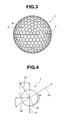
- FIG. 3 is a side view of the golf ball shown in FIG. 2, which view is seen from the equator side of the golf ball;
- FIG. 4 is an illustrative view for illustrating a relationship between a lift and a drag of a golf ball during flight thereof;
- FIG. 5 is a schematic sectional view showing a layer structure of the golf ball according to the present invention.
- FIG. 6 is a sectional view of a dimple of a golf ball according to a Comparative Example, which view is cut away along a plane passing through the center of the dimple.
- FIG. 1 is a sectional view of a dimple of the present invention, which view is cut away along a plane passing through the center of the dimple.
- FIG. 2 is a plan view of one example of the golf ball including the dimples shown in FIG. 1, which view is seen from a polar side of the golf ball, and
- FIG. 3 is a side view of the golf ball shown in FIG. 1, which view is seen from the equator side of the golf ball.
- reference numeral 1 denotes a golf ball
- 2 is a dimple
- 3 is the edge of the dimple
- 4 is a side wall of the dimple
- 5 is a bottom portion of the dimple
- character “O” denotes the center of the golf ball
- “R” is a radius of the golf ball.
- reference numeral 6 denotes a pole
- 7 is the equator
- 8 is a land.
- a golf ball 1 has a multiplicity of dimples 2 each of which is formed into a circular shape in a plan view.
- the dimples 2 are each configured to have a convex bottom portion shown in FIG. 1.
- the convex bottom portion is substantially formed by a circular-arc defined by a center positioned inside the ball and a radius “r” mm smaller than a radius “R” mm of the ball but larger than a value (R-0.5) mm.
- the number of the dimples on a ball surface is preferably in a range of 300 or more, more preferably, 330 or more, and preferably, 550 or less, more preferably, 500 or less.
- the shape, surrounded by the edge, of the dimple is not limited to a circular shape shown in FIGS. 2 and 3 but may be a non-circular shape, examples of which include a polygonal shape such as a triangular, quadrilateral, or hexagonal shape, an elliptic or oval shape, a petal shape, a heart shape, a star shape, a dewdrop shape, and a combination thereof. If the edge of the dimple is formed into such a non-circular shape in a plan view, the bottom portion of the dimple may be similarly formed into a non-circular shape in a plan view.
- the edge of the dimple is, however, preferable to be formed into a circular shape.
- the diameter of the dimple is preferably in a range of 2.0 mm or more, more preferably, 2.5 mm or more, and preferably, 6.0 mm or less, more preferably, 5.0 mm or less.
- the kind of the dimples is not limited to one, but is preferably in a range of two or more, more preferably, three or more, and generally, eight or less, particularly, six or less.
- the golf ball shown in FIG. 2 has three kinds of dimples: large dimples 2 a, middle dimples 2 b, and small dimples 2 c.
- part or all of the dimples are each configured to have a convex bottom portion formed by a circular-arc defined by the radius “r” mm smaller than the radius “R” mm of the ball but larger than the value (R-0.5) mm. That is to say, the radii “r” and “R” satisfy the following relationship:
- the radii “r” and “R” preferably satisfy the following relationship:
- the ratio d/D of a diameter “d” to a diameter D may be in a range of 1 ⁇ 5 or more, preferably, 1 ⁇ 4 or more, and 4 ⁇ 5 or less, preferably, 3 ⁇ 4 or less. If the ratio d/D is too small, the inclination of the side wall portion extending from the edge to the bottom portion of the dimple becomes too gentle, so that the dimple becomes analogous to the dimple having a circular-arc shape in cross section shown in FIG. 6, tending to lose the smoothness of the surface of the ball.
- the depth “h” of the dimple having the convex bottom portion is preferably in a range of 0.05 mm or more, more preferably, 0.1 mm or more, and preferably, 0.3 mm or less, more preferably, 0.2 mm or less.
- the circle defined by the radius “r” is not necessarily concentric with the circle defined by the radius “R”, but is preferably concentric therewith.
- the radius “R” of the ball is a radius of a circular arc shown by an imaginary line (dashed line) 9 connecting land portions to each other, and the radius “r” of the bottom portion is set to a value “R-0.2” mm by setting the depth “h” (equal to “R-r”) from the land portion extension line 9 to the surface of the bottom portion 5 to 0.2 mm.
- the diameter “d” of the dimple bottom portion which is formed by the circular-arc (radius: “r”) substantially concentric with the circular arc (radius: “R”) of the ball in cross-section, is about a half of the diameter D of the dimple in a plan view.
- the dimples have three kinds (large, middle, small) of the diameters D, and it is assumed that all of the dimples have the convex bottom portions each of which is formed by the circular-arc defined by the radius “r” shown in FIG. 1. According to the present invention, it is specified such that at least one or more of the dimples have convex bottom portions.
- the ratio of the dimples having convex bottom portions to the total of the dimples may be in a range of 50 % or more, preferably, 75% or more, more preferably, 80%, most preferably, 100%.
- the dimples may be arranged on the surface of the golf ball in accordance with any one of the known arrangement methods such as an icosahedron or octahedron arrangement method. It is to be noted that in the example shown in FIGS. 2 and 3, the dimples are arranged on the surface of the golf ball in accordance with the icosahedron arrangement method.
- the ratio CL/DL (CL: lift coefficient of ball during flight, DL: drag coefficient of ball during flight) is preferred to be in a range of 0.676 to 0.796 under a condition with a Reynolds number of 200,000 and a spin rate of 2,700 rpm, in a range of 0.813 to 0.933 under a condition with a Reynolds number of 120,000 and a spin rate of 2,400 rpm, and in a range of 0.856 to 0.976 under a condition with a Reynolds number of 80,000 and a spin rate of 2,000 rpm.
- a golf ball 1 hit with a club receives, during flight, a gravitational force 11 , an air resistance (drag) 12 , and a lift 13 by a Magnus effect due to the spin of the ball.
- reference numeral 14 denotes the flight direction
- 15 is the center of the ball
- 16 is the rotational direction of the ball.
- F is a force applied to the golf ball
- FL is a lift
- FD is a drag
- Mg is a gravitational force
- CL is a lift coefficient
- CD is a drag coefficient
- ⁇ is an air density
- A is the maximum cross-sectional area of the golf ball
- V is an air speed against the golf ball.
- the flight characteristics of the golf ball can be improved by combining the configuration that the ratio CL/CD is specified within the above-described range with the configuration that the cross-sectional shape of the golf ball is set to that shown in FIG. 1.
- the structure and the materials of the golf ball are not particularly limited.
- the golf ball of the present invention may be configured as a one-piece solid golf ball made from a single elastic material, a two-piece solid golf ball obtained by covering a center core made from an elastic material such as rubber with a cover made from a resin such as an ionomer resin or polyurethane, a multi-piece solid golf ball having three or more layers obtained by interposing, between a core and a cover, an intermediate layer portion composed of a single or two or more composite layers made from a resin material having physical properties different from those of a cover material.
- FIG. 5 is a sectional view of a layer structure of a three-piece solid golf ball including a core 21 made from rubber, an intermediate layer 22 made from a resin material, and a cover 23 having a multiplicity of dimples on the surface thereof, wherein the cover is formed so as to cover the core and the intermediate layer.
- Sample golf balls prepared in Example and Comparative Example each have the same layer structure as that shown in FIG. 5.
- Example and Comparative Example were each prepared as the three-layer solid golf ball shown in FIG. 5, wherein the core was formed by a single layer made from rubber, the intermediate layer was made from a composition containing an ionomer resin and an olefin based elastomer, and the cover was made from polyurethane elastomer.
- the thickness of the intermediate layer was 1.65 mm and the Shore D hardness of the intermediate layer, measured on the spherical surface, was 61; and the thickness of the cover was 1.5 mm and the Shore D hardness of the cover, measured on a land portion of the ball, was 58.
- the dimples provided on the golf ball in Example were all configured as dimples having the same cross-sectional shapes as those shown in FIG. 1, and the dimples provided on the golf ball in Comparative Example were all configured as dimples having the same shapes as those shown in FIG. 6.
- the details of structures of the dimples are shown in Table 1.
- the arrangement of the dimples provided on the golf balls in Example and Comparative Example was set as shown in FIGS. 2 and 3.
- the arrangement shown in FIGS. 2 and 3 is characterized in that there is no great circle not crossing the dimples, and more specifically, the equator as one of the great circles crosses the dimples as shown in FIG. 3, that is, the dimples slightly crossing the equator are periodically arranged along the equator.
- the diameter (equivalent to 2R in FIGS. 1 and 6) of each of the golf balls in Example and Comparative Example is 42.7 mm;
- the diameter “D” is a diameter of the circle, surrounded by the edge, of the dimple, and the diameter “d” is a diameter of the circle, surrounded by the edge, of the convex bottom portion (formed by the circular-arc defined by the radius “r”) as shown in FIGS. 1 and 6;
- the depth in Example is equivalent to the value “h” shown in FIG. 1
- the depth in Comparative Example is equivalent to the value “i” shown in FIG. 6.
- a comparison test was performed by mounting a driver (#1) to a hitting machine, and hitting each of the sample golf balls under a condition with an initial velocity of 72 m/s, a launch angle of 10°, and a spin rate of 2,700 rpm. The results of the test are shown in Table 2.
- the maximum point in the ball position column is a position of the ball during flight regarded as the maximum point (the highest point) by visual observation of an observer on the ground, and the minimum velocity point is a nearly intermediate point between the maximum point and the landing point.
Abstract
Description
- The present invention relates to a golf ball excellent in flight characteristics.
- As is well known, to improve flight characteristics of a golf ball, that is, to obtain the largest travel distance of the ball hit with a golf club, it is important to increase the resilience of the ball and to reduce the air resistance during flight caused by dimples arranged on the outer surface of the ball. With respect to the latter factor, from the viewpoint of reducing the air resistance caused by the dimples, various attempts have been made to improve the shapes of the dimples, to improve the arrangement of the dimples so as to distribute the dimples as uniformly and densely as possible, and to obtain the optimum ratio of dimple volumes to the total volume of the ball.
- The shape of a dimple in a plan view is generally circular, and the shape of a dimple in a cross-sectional view is generally selected from various kinds of shapes. The first cross-sectional shape of the dimple is a nearly circular-arc shape as a whole. To be more specific, as shown in the cross-section of FIG. 6, an outline, extending from both edges to a bottom portion via side walls, of a dimple is formed by a circular-arc defined by a curvature radius “f” and the center positioned outside the golf ball. In the figure,
reference numeral 1 denotes the golf ball, 2 is the dimple, 3 is the edge of the dimple, 4 is the side wall of the dimple, and 5 is the bottom portion of the dimple, and further, character “O” denotes the center of the golf ball, “R” is the radius of the golf ball, “f” is the curvature radius of the wall surface of thedimple 2 the center of which is “P” positioned outside the ball, and “i” is the depth of the dimple. - The known second cross-sectional shape of the dimple is a double shape composed of a combination of a large circular-arc and a small circular-arc. In general, the side wall portion is formed by the large-circular arc and the bottom portion is formed by the small circular-arc. The third cross-sectional shape of the dimple is configured such that the bottom portion is formed into a shape similar to that of the bottom of a pot or a shape similar to that of a caldera. The caldera shape is a modification of the double shape, wherein the bottom portion formed by a small circular-arc projects outwardly from the ball.
- Nevertheless, it has been expected yet to obtain more desirable flight characteristics of a golf ball by improving the shapes of dimples.
- An object of the present invention is to provide a golf ball including dimples on its outer surface, which is capable of improving flight characteristics thereof by optimizing shapes of the dimples.
- To achieve the above object, according to an aspect of the present invention, there is provided a golf ball including a multiplicity of dimples on its outer surface, wherein at least one or more of the multiplicity of dimples are each configured to have a convex bottom portion formed by a circular-arc defined by a center positioned inside the ball and a curvature radius “r” mm smaller than a radius “R” mm of the ball but larger than a value (R-0.5) mm.
- The dimple having the convex bottom portion is preferably formed into a circular shape in a plan view.
- The dimple having the convex bottom portion is also preferably formed into a non-circular shape in a plan view.
- In the golf ball, preferably, a ratio CL/CD of a lift coefficient CL to a drag coefficient CD of the ball during flight thereof is in a range of 0.676 to 0.796 under a condition with a Reynolds number of 200,000 and a spin rate of 2,700 rpm, in a range of 0.813 to 0.933 under a condition with a Reynolds number of 12,000 and a spin rate of 2,400 rpm, and in a range of 0.856 to 0.976 under a condition with a Reynolds number of 80,000 and a spin rate of 2,000 rpm.
- According to the present invention, unlike the prior art cross-sectional shapes of dimples, at least one or more of a multiplicity of dimples are each configured to have a bottom portion whose shape is specified to significantly smoothen the surface of the golf ball. As a result, it is possible to improve flight characteristics of the golf ball.
- These and other objects, features, and advantages of the present invention will be more apparent from the following detailed description taken in conjunction with the accompanying drawings, in which:
- FIG. 1 is a sectional view of a dimple provided on a golf ball according to the present invention, which view is cut away along a plane passing through the center of the dimple;
- FIG. 2 is a plan view of one example of the golf ball according to the present invention, which view is seen from a polar side of the golf ball;
- FIG. 3 is a side view of the golf ball shown in FIG. 2, which view is seen from the equator side of the golf ball;
- FIG. 4 is an illustrative view for illustrating a relationship between a lift and a drag of a golf ball during flight thereof;
- FIG. 5 is a schematic sectional view showing a layer structure of the golf ball according to the present invention; and
- FIG. 6 is a sectional view of a dimple of a golf ball according to a Comparative Example, which view is cut away along a plane passing through the center of the dimple.
- The present invention will now be described with reference to FIGS. 1 to 5.
- FIG. 1 is a sectional view of a dimple of the present invention, which view is cut away along a plane passing through the center of the dimple. FIG. 2 is a plan view of one example of the golf ball including the dimples shown in FIG. 1, which view is seen from a polar side of the golf ball, and FIG. 3 is a side view of the golf ball shown in FIG. 1, which view is seen from the equator side of the golf ball.
- In these figures, like FIG. 6,
reference numeral 1 denotes a golf ball, 2 is a dimple, 3 is the edge of the dimple, 4 is a side wall of the dimple, 5 is a bottom portion of the dimple, and further, character “O” denotes the center of the golf ball, and “R” is a radius of the golf ball. In addition,reference numeral 6 denotes a pole, 7 is the equator, and 8 is a land. - Referring to FIGS. 2 and 3, a
golf ball 1 has a multiplicity ofdimples 2 each of which is formed into a circular shape in a plan view. In this case, according to the present invention, at least one or more of thedimples 2 are each configured to have a convex bottom portion shown in FIG. 1. The convex bottom portion is substantially formed by a circular-arc defined by a center positioned inside the ball and a radius “r” mm smaller than a radius “R” mm of the ball but larger than a value (R-0.5) mm. - The number of the dimples on a ball surface is preferably in a range of 300 or more, more preferably, 330 or more, and preferably, 550 or less, more preferably, 500 or less.
- The shape, surrounded by the edge, of the dimple is not limited to a circular shape shown in FIGS. 2 and 3 but may be a non-circular shape, examples of which include a polygonal shape such as a triangular, quadrilateral, or hexagonal shape, an elliptic or oval shape, a petal shape, a heart shape, a star shape, a dewdrop shape, and a combination thereof. If the edge of the dimple is formed into such a non-circular shape in a plan view, the bottom portion of the dimple may be similarly formed into a non-circular shape in a plan view.
- The edge of the dimple is, however, preferable to be formed into a circular shape. In this case, the diameter of the dimple is preferably in a range of 2.0 mm or more, more preferably, 2.5 mm or more, and preferably, 6.0 mm or less, more preferably, 5.0 mm or less.
- According to the present invention, the kind of the dimples is not limited to one, but is preferably in a range of two or more, more preferably, three or more, and generally, eight or less, particularly, six or less. The golf ball shown in FIG. 2 has three kinds of dimples:
large dimples 2 a,middle dimples 2 b, andsmall dimples 2 c. - According to the present invention, as described above, part or all of the dimples are each configured to have a convex bottom portion formed by a circular-arc defined by the radius “r” mm smaller than the radius “R” mm of the ball but larger than the value (R-0.5) mm. That is to say, the radii “r” and “R” satisfy the following relationship:
- R>r>R-0.5
- In this case, from the viewpoint of flight characteristics of the ball, the radii “r” and “R” preferably satisfy the following relationship:
- R-0.1>r>R-0.4
- The ratio d/D of a diameter “d” to a diameter D may be in a range of ⅕ or more, preferably, ¼ or more, and ⅘ or less, preferably, ¾ or less. If the ratio d/D is too small, the inclination of the side wall portion extending from the edge to the bottom portion of the dimple becomes too gentle, so that the dimple becomes analogous to the dimple having a circular-arc shape in cross section shown in FIG. 6, tending to lose the smoothness of the surface of the ball.
- The depth “h” of the dimple having the convex bottom portion is preferably in a range of 0.05 mm or more, more preferably, 0.1 mm or more, and preferably, 0.3 mm or less, more preferably, 0.2 mm or less.
- The circle defined by the radius “r” is not necessarily concentric with the circle defined by the radius “R”, but is preferably concentric therewith.
- According to the embodiment shown in FIG. 1, the radius “R” of the ball is a radius of a circular arc shown by an imaginary line (dashed line) 9 connecting land portions to each other, and the radius “r” of the bottom portion is set to a value “R-0.2” mm by setting the depth “h” (equal to “R-r”) from the land
portion extension line 9 to the surface of thebottom portion 5 to 0.2 mm. The diameter “d” of the dimple bottom portion, which is formed by the circular-arc (radius: “r”) substantially concentric with the circular arc (radius: “R”) of the ball in cross-section, is about a half of the diameter D of the dimple in a plan view. - According to the example shown in FIGS. 2 and 3, the dimples have three kinds (large, middle, small) of the diameters D, and it is assumed that all of the dimples have the convex bottom portions each of which is formed by the circular-arc defined by the radius “r” shown in FIG. 1. According to the present invention, it is specified such that at least one or more of the dimples have convex bottom portions. In this case, the ratio of the dimples having convex bottom portions to the total of the dimples may be in a range of 50 % or more, preferably, 75% or more, more preferably, 80%, most preferably, 100%.
- The dimples may be arranged on the surface of the golf ball in accordance with any one of the known arrangement methods such as an icosahedron or octahedron arrangement method. It is to be noted that in the example shown in FIGS. 2 and 3, the dimples are arranged on the surface of the golf ball in accordance with the icosahedron arrangement method.
- According to the present invention, the ratio CL/DL (CL: lift coefficient of ball during flight, DL: drag coefficient of ball during flight) is preferred to be in a range of 0.676 to 0.796 under a condition with a Reynolds number of 200,000 and a spin rate of 2,700 rpm, in a range of 0.813 to 0.933 under a condition with a Reynolds number of 120,000 and a spin rate of 2,400 rpm, and in a range of 0.856 to 0.976 under a condition with a Reynolds number of 80,000 and a spin rate of 2,000 rpm.
- To be more specific, to ensure the long travel distance, particularly, against wind and prolong the run of a golf ball hit with a long-distance club such as a wood club #1 (driver), it is required to take a balance between the lift and drag of the ball during flight, and the travel distance of the golf ball is dependent on the kind, total number, surface occupied ratio, total volume, and the like of the dimples.
- It is known that as shown in FIG. 4, a
golf ball 1 hit with a club receives, during flight, agravitational force 11, an air resistance (drag) 12, and alift 13 by a Magnus effect due to the spin of the ball. In the figure,reference numeral 14 denotes the flight direction, 15 is the center of the ball, and 16 is the rotational direction of the ball. - In this case, a force applied to the golf ball is expressed by the following trajectory equation:
- F=FL+FD+Mg (1)
- Where F is a force applied to the golf ball, FL is a lift, FD is a drag, and Mg is a gravitational force.
- The lift FL and the drag FD in the trajectory equation (1) are given by the following equations:
- FL=0.5×CL×ρ×A×V 2 (2)
- FD=0.5×CD×ρ×A×V 2 (3)
- Where CL is a lift coefficient, CD is a drag coefficient, ρ is an air density, A is the maximum cross-sectional area of the golf ball, and V is an air speed against the golf ball.
- According to the golf ball of the present invention, the flight characteristics of the golf ball can be improved by combining the configuration that the ratio CL/CD is specified within the above-described range with the configuration that the cross-sectional shape of the golf ball is set to that shown in FIG. 1.
- According to the present invention, the structure and the materials of the golf ball are not particularly limited. For example, the golf ball of the present invention may be configured as a one-piece solid golf ball made from a single elastic material, a two-piece solid golf ball obtained by covering a center core made from an elastic material such as rubber with a cover made from a resin such as an ionomer resin or polyurethane, a multi-piece solid golf ball having three or more layers obtained by interposing, between a core and a cover, an intermediate layer portion composed of a single or two or more composite layers made from a resin material having physical properties different from those of a cover material.
- According to the golf ball of the present invention, since the shapes of the dimples are optimized as described above, flight characteristics of the golf ball can be improved.
- The present invention will be more apparent by way of the following Example and Comparative Example. These examples, however, should not be construed as limiting the present invention.
- FIG. 5 is a sectional view of a layer structure of a three-piece solid golf ball including a core 21 made from rubber, an
intermediate layer 22 made from a resin material, and acover 23 having a multiplicity of dimples on the surface thereof, wherein the cover is formed so as to cover the core and the intermediate layer. - Sample golf balls prepared in Example and Comparative Example each have the same layer structure as that shown in FIG. 5.
- To confirm flight characteristics of the golf ball according to the present invention, the lift, the drag, and the flying distance of each of the sample golf balls prepared in one Example and one Comparative Example were measured.
- The sample golf balls in Example and Comparative Example were each prepared as the three-layer solid golf ball shown in FIG. 5, wherein the core was formed by a single layer made from rubber, the intermediate layer was made from a composition containing an ionomer resin and an olefin based elastomer, and the cover was made from polyurethane elastomer. In each of the sample golf balls in Example and Comparative Example, the thickness of the intermediate layer was 1.65 mm and the Shore D hardness of the intermediate layer, measured on the spherical surface, was 61; and the thickness of the cover was 1.5 mm and the Shore D hardness of the cover, measured on a land portion of the ball, was 58.
- The dimples provided on the golf ball in Example were all configured as dimples having the same cross-sectional shapes as those shown in FIG. 1, and the dimples provided on the golf ball in Comparative Example were all configured as dimples having the same shapes as those shown in FIG. 6. The details of structures of the dimples are shown in Table 1. The arrangement of the dimples provided on the golf balls in Example and Comparative Example was set as shown in FIGS. 2 and 3. The arrangement shown in FIGS. 2 and 3 is characterized in that there is no great circle not crossing the dimples, and more specifically, the equator as one of the great circles crosses the dimples as shown in FIG. 3, that is, the dimples slightly crossing the equator are periodically arranged along the equator.
TABLE 1 Radius r Kind (mm) Total of Diameter D Diameter d of bottom Depth volume dimples (mm) (mm) portion (mm) Number (mm3) Example {circumflex over (1)} 4.05 2.10 21.15 0.20 296 368 315 {circumflex over (2)} 3.50 1.80 21.15 0.20 60 {circumflex over (3)} 2.40 1.15 21.15 0.20 12 Comparative {circumflex over (1)} 4.05 — — 0.25 296 368 313 Example {circumflex over (2)} 3.50 — — 0.22 60 {circumflex over (3)} 2.40 — — 0.16 12 - In Table 1, the diameter (equivalent to 2R in FIGS. 1 and 6) of each of the golf balls in Example and Comparative Example is 42.7 mm; the diameter “D” is a diameter of the circle, surrounded by the edge, of the dimple, and the diameter “d” is a diameter of the circle, surrounded by the edge, of the convex bottom portion (formed by the circular-arc defined by the radius “r”) as shown in FIGS. 1 and 6; and the depth in Example is equivalent to the value “h” shown in FIG. 1, and the depth in Comparative Example is equivalent to the value “i” shown in FIG. 6.
- A comparison test was performed by mounting a driver (#1) to a hitting machine, and hitting each of the sample golf balls under a condition with an initial velocity of 72 m/s, a launch angle of 10°, and a spin rate of 2,700 rpm. The results of the test are shown in Table 2.
TABLE 2 Position Velocity V Spin rate Reynolds Comparative of ball (m/s) (rpm) number Example Example Immediately 72.0 2700 200000 CL 0.159 0.155 after CD 0.220 0.233 launch CL/CD 0.723 0.670 Maximum 41.4 2400 120000 CL 0.215 0.210 point CD 0.247 0.255 CL/CD 0.870 0.824 Minimum 26.4 2000 80000 CL 0.257 0.256 velocity CD 0.281 0.283 point CL/CD 0.916 0.906 Flying Distance (m) Carry 242 239 Total 261 258 - In Table 2, the maximum point in the ball position column is a position of the ball during flight regarded as the maximum point (the highest point) by visual observation of an observer on the ground, and the minimum velocity point is a nearly intermediate point between the maximum point and the landing point.
- From the results shown in Table 2, it is apparent that the flight characteristics (both the carry and total) of the golf ball in Example, which ball is configured such that the shapes of the dimples are specified according to the present invention and the ratio CL/CD is within the range specified according to the present invention, can be significantly improved.
- While the preferred embodiment of the present invention has been described using specific terms, such description is for illustrative purposes only, and it is to be understood that many changes and variations may be made without departing from the spirit or scope of the following claims.
Claims (4)
Applications Claiming Priority (2)
| Application Number | Priority Date | Filing Date | Title |
|---|---|---|---|
| JP2002-094285 | 2002-03-29 | ||
| JP2002094285A JP4120773B2 (en) | 2002-03-29 | 2002-03-29 | Golf ball |
Publications (2)
| Publication Number | Publication Date |
|---|---|
| US20030190968A1 true US20030190968A1 (en) | 2003-10-09 |
| US7018308B2 US7018308B2 (en) | 2006-03-28 |
Family
ID=28671783
Family Applications (1)
| Application Number | Title | Priority Date | Filing Date |
|---|---|---|---|
| US10/392,968 Expired - Lifetime US7018308B2 (en) | 2002-03-29 | 2003-03-21 | Golf ball |
Country Status (2)
| Country | Link |
|---|---|
| US (1) | US7018308B2 (en) |
| JP (1) | JP4120773B2 (en) |
Cited By (11)
| Publication number | Priority date | Publication date | Assignee | Title |
|---|---|---|---|---|
| US20070259739A1 (en) * | 2006-01-17 | 2007-11-08 | Bridgestone Sports Co., Ltd. | Golf ball |
| WO2010118397A2 (en) * | 2009-04-09 | 2010-10-14 | Aero-X Golf Inc. | A low lift golf ball |
| US20110195802A1 (en) * | 2010-02-10 | 2011-08-11 | Hirotaka Nakamura | Golf ball |
| US20130196790A1 (en) * | 2010-04-09 | 2013-08-01 | Bridgestone Sports Co., Ltd. | Multi-piece solid golf ball |
| US8956252B2 (en) | 2010-07-08 | 2015-02-17 | Sri Sports Limited | Golf ball |
| US20150182806A1 (en) * | 2013-12-27 | 2015-07-02 | Dunlop Sports Co. Ltd. | Golf ball and method for producing the same |
| US9211442B2 (en) | 2011-03-16 | 2015-12-15 | Aero-X Golf, Inc. | Anti-slice golf ball construction |
| US20160114219A1 (en) * | 2012-12-28 | 2016-04-28 | Dunlop Sports Co. Ltd. | Golf ball |
| US10118696B1 (en) | 2016-03-31 | 2018-11-06 | Steven M. Hoffberg | Steerable rotating projectile |
| US10486027B1 (en) * | 2018-10-02 | 2019-11-26 | Mizuno Corporation | Golf ball |
| US11712637B1 (en) | 2018-03-23 | 2023-08-01 | Steven M. Hoffberg | Steerable disk or ball |
Families Citing this family (17)
| Publication number | Priority date | Publication date | Assignee | Title |
|---|---|---|---|---|
| JPH0634672U (en) * | 1992-02-28 | 1994-05-10 | 株式会社コルテス | Ballistic trajectory measuring device |
| US8591355B2 (en) * | 2002-02-15 | 2013-11-26 | Acushnet Company | Golf ball with dimples having constant depth |
| US7229364B2 (en) * | 2002-05-23 | 2007-06-12 | Acushnet Company | Golf ball dimples |
| US7018309B2 (en) * | 2004-05-04 | 2006-03-28 | Bridgestone Sports Co., Ltd. | Golf ball |
| US7367905B2 (en) | 2006-01-17 | 2008-05-06 | Bridgestone Sports Co., Ltd. | Golf ball |
| US8002647B2 (en) * | 2008-10-10 | 2011-08-23 | Bridgestone Sports Co., Ltd. | Golf ball |
| US20130225333A1 (en) * | 2010-04-09 | 2013-08-29 | Bridgestone Sports Co., Ltd. | Multi-piece solid golf ball |
| US10758785B2 (en) | 2010-12-22 | 2020-09-01 | Acushnet Company | Golf ball dimples defined by superposed curves |
| US10232223B2 (en) * | 2010-12-22 | 2019-03-19 | Acushnet Company | Golf ball dimples defined by superposed curves |
| US20150119171A1 (en) | 2010-12-22 | 2015-04-30 | Acushnet Company | Golf ball dimples defined by superposed curves |
| US9782630B2 (en) * | 2010-12-22 | 2017-10-10 | Acushnet Company | Golf ball dimples defined by superposed curves |
| US20130172127A1 (en) * | 2011-12-30 | 2013-07-04 | Chris Hixenbaugh | Golf ball dimple profile |
| US20130172124A1 (en) * | 2011-12-30 | 2013-07-04 | Chris Hixenbaugh | Golf ball dimple profile |
| JP6304631B2 (en) * | 2014-06-30 | 2018-04-04 | 住友ゴム工業株式会社 | Golf ball |
| USD868912S1 (en) * | 2017-05-09 | 2019-12-03 | Volvik, Inc. | Golf ball |
| USD823956S1 (en) * | 2017-05-19 | 2018-07-24 | Nexen Corporation | Golf ball |
| JP7366721B2 (en) | 2019-12-09 | 2023-10-23 | ブリヂストンスポーツ株式会社 | Golf ball |
Citations (3)
| Publication number | Priority date | Publication date | Assignee | Title |
|---|---|---|---|---|
| US5005838A (en) * | 1989-05-09 | 1991-04-09 | Sumitomo Rubber Industries, Ltd. | Golf ball |
| US6290615B1 (en) * | 1999-11-18 | 2001-09-18 | Callaway Golf Company | Golf ball having a tubular lattice pattern |
| US6569038B2 (en) * | 2001-05-02 | 2003-05-27 | Acushnet Company | Golf ball dimples |
-
2002
- 2002-03-29 JP JP2002094285A patent/JP4120773B2/en not_active Expired - Lifetime
-
2003
- 2003-03-21 US US10/392,968 patent/US7018308B2/en not_active Expired - Lifetime
Patent Citations (3)
| Publication number | Priority date | Publication date | Assignee | Title |
|---|---|---|---|---|
| US5005838A (en) * | 1989-05-09 | 1991-04-09 | Sumitomo Rubber Industries, Ltd. | Golf ball |
| US6290615B1 (en) * | 1999-11-18 | 2001-09-18 | Callaway Golf Company | Golf ball having a tubular lattice pattern |
| US6569038B2 (en) * | 2001-05-02 | 2003-05-27 | Acushnet Company | Golf ball dimples |
Cited By (83)
| Publication number | Priority date | Publication date | Assignee | Title |
|---|---|---|---|---|
| US20070259739A1 (en) * | 2006-01-17 | 2007-11-08 | Bridgestone Sports Co., Ltd. | Golf ball |
| US7452292B2 (en) * | 2006-01-17 | 2008-11-18 | Bridgestone Sports Co., Ltd. | Golf ball |
| US8192307B2 (en) | 2009-04-09 | 2012-06-05 | Aero-X Golf, Inc. | Low lift golf ball |
| US20100273579A1 (en) * | 2009-04-09 | 2010-10-28 | Aero-X Golf Inc. | Low lift golf ball |
| US20100261556A1 (en) * | 2009-04-09 | 2010-10-14 | Aero-X Golf Inc. | Low lift golf ball |
| US20100261551A1 (en) * | 2009-04-09 | 2010-10-14 | Aero-X Golf Inc. | Low lift golf ball |
| WO2010118396A2 (en) * | 2009-04-09 | 2010-10-14 | Aero-X Golf Inc. | A low lift golf ball |
| US20100267471A1 (en) * | 2009-04-09 | 2010-10-21 | Aero-X Golf Inc. | Low lift golf ball |
| US20100267489A1 (en) * | 2009-04-09 | 2010-10-21 | Aero-X Golf Inc. | Low lift golf ball |
| US20100267488A1 (en) * | 2009-04-09 | 2010-10-21 | Aero-X Golf Inc. | Low lift golf ball |
| US20100267474A1 (en) * | 2009-04-09 | 2010-10-21 | Aero-X Golf Inc. | Low lift golf ball |
| US20100267472A1 (en) * | 2009-04-09 | 2010-10-21 | Aero-X Golf Inc. | Low lift golf ball |
| US20100267470A1 (en) * | 2009-04-09 | 2010-10-21 | Aero-X Golf Inc. | Low lift golf ball |
| US20100267475A1 (en) * | 2009-04-09 | 2010-10-21 | Aero-X Golf Inc. | Low lift golf ball |
| US20100267483A1 (en) * | 2009-04-09 | 2010-10-21 | Aero-X Golf Inc. | Low lift golf ball |
| US20100267491A1 (en) * | 2009-04-09 | 2010-10-21 | Aero-X Golf Inc. | Low lift golf ball |
| US20100267485A1 (en) * | 2009-04-09 | 2010-10-21 | Aero-X Golf Inc. | Low lift golf ball |
| US8202179B2 (en) | 2009-04-09 | 2012-06-19 | Aero-X Golf, Inc. | Low lift golf ball |
| US20100267473A1 (en) * | 2009-04-09 | 2010-10-21 | Aero-X Golf Inc. | Low lift golf ball |
| US20100267476A1 (en) * | 2009-04-09 | 2010-10-21 | Aero-X Golf Inc. | Low lift golf ball |
| US20100267480A1 (en) * | 2009-04-09 | 2010-10-21 | Aero-X Golf Inc. | Low lift golf ball |
| US20100267477A1 (en) * | 2009-04-09 | 2010-10-21 | Aero-X Golf Inc. | Low lift golf ball |
| US20100267481A1 (en) * | 2009-04-09 | 2010-10-21 | Aero-X Golf Inc. | Low lift golf ball |
| US20100267479A1 (en) * | 2009-04-09 | 2010-10-21 | Aero-X Golf Inc. | Low lift golf ball |
| US20100267482A1 (en) * | 2009-04-09 | 2010-10-21 | Aero-X Golf Inc. | low lift golf ball |
| US20100267478A1 (en) * | 2009-04-09 | 2010-10-21 | Aero-X Golf Inc. | low lift golf ball |
| US20100267490A1 (en) * | 2009-04-09 | 2010-10-21 | Aero-X Golf Inc. | Low lift golf ball |
| US20100267469A1 (en) * | 2009-04-09 | 2010-10-21 | Aero-X Golf Inc. | Low lift golf ball |
| US20100267486A1 (en) * | 2009-04-09 | 2010-10-21 | Aero-X Golf Inc. | Low lift golf ball |
| US20100267484A1 (en) * | 2009-04-09 | 2010-10-21 | Aero-X Golf Inc. | Low lift golf ball |
| US20100273578A1 (en) * | 2009-04-09 | 2010-10-28 | Aero-X Golf Inc. | Low lift golf ball |
| US20100273582A1 (en) * | 2009-04-09 | 2010-10-28 | Aero-X Golf Inc. | Low lift golf ball |
| US20100273581A1 (en) * | 2009-04-09 | 2010-10-28 | Aero-X Golf Inc. | Low lift golf ball |
| US20100273580A1 (en) * | 2009-04-09 | 2010-10-28 | Aero-X Golf Inc. | Low lift golf ball |
| US8197361B2 (en) | 2009-04-09 | 2012-06-12 | Aero-X Golf, Inc. | Low lift golf ball |
| US20100323822A1 (en) * | 2009-04-09 | 2010-12-23 | Aero-X Golf Inc. | Low lift golf ball |
| WO2010118396A3 (en) * | 2009-04-09 | 2011-01-13 | Aero-X Golf Inc. | A low lift golf ball |
| WO2010118397A3 (en) * | 2009-04-09 | 2011-01-13 | Aero-X Golf Inc. | A low lift golf ball |
| US20110081992A1 (en) * | 2009-04-09 | 2011-04-07 | Aero-X Golf Inc. | Low lift golf ball |
| US8795103B2 (en) | 2009-04-09 | 2014-08-05 | Aero-X Golf, Inc. | Low lift golf ball |
| US8192306B2 (en) | 2009-04-09 | 2012-06-05 | Aero-X Golf, Inc. | Low lift golf ball |
| WO2010118397A2 (en) * | 2009-04-09 | 2010-10-14 | Aero-X Golf Inc. | A low lift golf ball |
| US8038548B2 (en) | 2009-04-09 | 2011-10-18 | Aero-X Golf, Inc. | Low lift golf ball |
| US20100261555A1 (en) * | 2009-04-09 | 2010-10-14 | Aero-X Golf Inc. | Low lift golf ball |
| US20100267487A1 (en) * | 2009-04-09 | 2010-10-21 | Aero-X Golf Inc. | Low lift golf ball |
| US8202178B2 (en) | 2009-04-09 | 2012-06-19 | Aero-X Golf, Inc. | Low lift golf ball |
| US8226502B2 (en) | 2009-04-09 | 2012-07-24 | Aero-X Golf, Inc. | Low lift golf ball |
| US8246490B2 (en) | 2009-04-09 | 2012-08-21 | Aero-X Golf, Inc. | Low lift golf ball |
| US8251840B2 (en) | 2009-04-09 | 2012-08-28 | Aero-X Golf, Inc. | Low lift golf ball |
| US8262513B2 (en) | 2009-04-09 | 2012-09-11 | Aero-X Golf, Inc. | Low lift golf ball |
| US8267810B2 (en) | 2009-04-09 | 2012-09-18 | Aero-X Golf, Inc. | Low lift golf ball |
| US8323124B2 (en) | 2009-04-09 | 2012-12-04 | Aero-X Golf, Inc. | Low lift golf ball |
| US8366569B2 (en) | 2009-04-09 | 2013-02-05 | Aero-X Golf Inc. | Low lift golf ball |
| US8371961B2 (en) | 2009-04-09 | 2013-02-12 | Aero-X Golf Inc. | Low lift golf ball |
| US8382613B2 (en) | 2009-04-09 | 2013-02-26 | Aero-X Golf Inc. | Low lift golf ball |
| US8388467B2 (en) | 2009-04-09 | 2013-03-05 | Aero-X Golf, Inc. | Low lift golf ball |
| US8388468B2 (en) | 2009-04-09 | 2013-03-05 | Aero-X Golf, Inc. | Low lift golf ball |
| US8454456B2 (en) | 2009-04-09 | 2013-06-04 | Aero-X Golf, Inc. | Low lift golf ball |
| US8475299B2 (en) | 2009-04-09 | 2013-07-02 | Aero-X Golf, Inc. | Low lift golf ball |
| US8491419B2 (en) | 2009-04-09 | 2013-07-23 | Aero-X Golf, Inc. | Low lift golf ball |
| US8491420B2 (en) | 2009-04-09 | 2013-07-23 | Aero-X Golf, Inc. | Low lift golf ball |
| US8708840B2 (en) | 2009-04-09 | 2014-04-29 | Aero-X Golf, Inc. | Low lift golf ball |
| US8512167B2 (en) | 2009-04-09 | 2013-08-20 | Aero-X Golf, Inc. | Low lift golf ball |
| US8550937B2 (en) | 2009-04-09 | 2013-10-08 | Aero-X Golf, Inc | Low lift golf ball |
| US8550938B2 (en) | 2009-04-09 | 2013-10-08 | Aero-X Golf, Inc. | Low lift golf ball |
| US8574098B2 (en) | 2009-04-09 | 2013-11-05 | Aero-X Golf, Inc | Low lift golf ball |
| US8579730B2 (en) | 2009-04-09 | 2013-11-12 | Aero-X Golf, Inc. | Low lift golf ball |
| US8602916B2 (en) | 2009-04-09 | 2013-12-10 | Aero-X Golf, Inc. | Low lift golf ball |
| US8622852B2 (en) | 2009-04-09 | 2014-01-07 | Aero-X Golf, Inc. | Low lift golf ball |
| US8657706B2 (en) | 2009-04-09 | 2014-02-25 | Aero-X Golf, Inc. | Low lift golf ball |
| US8708839B2 (en) | 2009-04-09 | 2014-04-29 | Aero-X Golf, Inc. | Low lift golf ball |
| US20110195802A1 (en) * | 2010-02-10 | 2011-08-11 | Hirotaka Nakamura | Golf ball |
| US8834302B2 (en) | 2010-02-10 | 2014-09-16 | Sri Sports Limited | Golf ball |
| US20130196790A1 (en) * | 2010-04-09 | 2013-08-01 | Bridgestone Sports Co., Ltd. | Multi-piece solid golf ball |
| US8956252B2 (en) | 2010-07-08 | 2015-02-17 | Sri Sports Limited | Golf ball |
| US9211442B2 (en) | 2011-03-16 | 2015-12-15 | Aero-X Golf, Inc. | Anti-slice golf ball construction |
| US20160114219A1 (en) * | 2012-12-28 | 2016-04-28 | Dunlop Sports Co. Ltd. | Golf ball |
| US9682282B2 (en) * | 2012-12-28 | 2017-06-20 | Dunlop Sports Co. Ltd. | Golf ball |
| US20150182806A1 (en) * | 2013-12-27 | 2015-07-02 | Dunlop Sports Co. Ltd. | Golf ball and method for producing the same |
| US10118696B1 (en) | 2016-03-31 | 2018-11-06 | Steven M. Hoffberg | Steerable rotating projectile |
| US11230375B1 (en) | 2016-03-31 | 2022-01-25 | Steven M. Hoffberg | Steerable rotating projectile |
| US11712637B1 (en) | 2018-03-23 | 2023-08-01 | Steven M. Hoffberg | Steerable disk or ball |
| US10486027B1 (en) * | 2018-10-02 | 2019-11-26 | Mizuno Corporation | Golf ball |
Also Published As
| Publication number | Publication date |
|---|---|
| US7018308B2 (en) | 2006-03-28 |
| JP4120773B2 (en) | 2008-07-16 |
| JP2003290390A (en) | 2003-10-14 |
Similar Documents
| Publication | Publication Date | Title |
|---|---|---|
| US7018308B2 (en) | Golf ball | |
| JP5221125B2 (en) | Golf ball with improved flight performance | |
| US7300363B2 (en) | Golf ball | |
| JP3080290B2 (en) | Golf ball | |
| JP4509231B2 (en) | Golf ball | |
| CA2060679C (en) | Golf ball | |
| US7384351B2 (en) | Golf ball | |
| JP2006142012A (en) | Golf ball | |
| US7367905B2 (en) | Golf ball | |
| US6454668B2 (en) | Golf ball | |
| US6969327B2 (en) | Golf ball dimple pattern with overlapping dimples | |
| US20100240473A1 (en) | Golf ball with improved symmetry | |
| JP3909124B2 (en) | Golf ball | |
| JP2007075600A (en) | Solid golf ball | |
| JPH04174680A (en) | Golf ball | |
| US7083533B2 (en) | Golf ball | |
| KR101197666B1 (en) | Golf ball with circular dimple having the radial concave surface concentrically | |
| JP2004290614A (en) | Golf ball | |
| JP5124811B2 (en) | Golf ball | |
| US9533194B2 (en) | Golf ball | |
| US6547679B2 (en) | Golf ball | |
| US10150005B2 (en) | Golf ball | |
| JP4143775B2 (en) | Golf ball | |
| JP4054928B2 (en) | Golf ball | |
| JP2001054591A (en) | Golf ball |
Legal Events
| Date | Code | Title | Description |
|---|---|---|---|
| AS | Assignment |
Owner name: BRIDGESTONE SPORTS CO., LTD., JAPAN Free format text: ASSIGNMENT OF ASSIGNORS INTEREST;ASSIGNOR:KASASHIMA, ATSUKI;REEL/FRAME:013905/0928 Effective date: 20030225 |
|
| FEPP | Fee payment procedure |
Free format text: PAYOR NUMBER ASSIGNED (ORIGINAL EVENT CODE: ASPN); ENTITY STATUS OF PATENT OWNER: LARGE ENTITY |
|
| STCF | Information on status: patent grant |
Free format text: PATENTED CASE |
|
| FPAY | Fee payment |
Year of fee payment: 4 |
|
| FPAY | Fee payment |
Year of fee payment: 8 |
|
| MAFP | Maintenance fee payment |
Free format text: PAYMENT OF MAINTENANCE FEE, 12TH YEAR, LARGE ENTITY (ORIGINAL EVENT CODE: M1553) Year of fee payment: 12 |