US20030191414A1 - Hand-held instruments that access interior body regions - Google Patents
Hand-held instruments that access interior body regions Download PDFInfo
- Publication number
- US20030191414A1 US20030191414A1 US10/431,681 US43168103A US2003191414A1 US 20030191414 A1 US20030191414 A1 US 20030191414A1 US 43168103 A US43168103 A US 43168103A US 2003191414 A1 US2003191414 A1 US 2003191414A1
- Authority
- US
- United States
- Prior art keywords
- handle
- instrument
- trocar
- cannula
- composite
- Prior art date
- Legal status (The legal status is an assumption and is not a legal conclusion. Google has not performed a legal analysis and makes no representation as to the accuracy of the status listed.)
- Granted
Links
Images


Classifications
-
- A—HUMAN NECESSITIES
- A61—MEDICAL OR VETERINARY SCIENCE; HYGIENE
- A61B—DIAGNOSIS; SURGERY; IDENTIFICATION
- A61B17/00—Surgical instruments, devices or methods, e.g. tourniquets
- A61B17/34—Trocars; Puncturing needles
-
- A—HUMAN NECESSITIES
- A61—MEDICAL OR VETERINARY SCIENCE; HYGIENE
- A61B—DIAGNOSIS; SURGERY; IDENTIFICATION
- A61B17/00—Surgical instruments, devices or methods, e.g. tourniquets
- A61B17/34—Trocars; Puncturing needles
- A61B17/3417—Details of tips or shafts, e.g. grooves, expandable, bendable; Multiple coaxial sliding cannulas, e.g. for dilating
-
- A—HUMAN NECESSITIES
- A61—MEDICAL OR VETERINARY SCIENCE; HYGIENE
- A61B—DIAGNOSIS; SURGERY; IDENTIFICATION
- A61B17/00—Surgical instruments, devices or methods, e.g. tourniquets
- A61B17/56—Surgical instruments or methods for treatment of bones or joints; Devices specially adapted therefor
- A61B17/58—Surgical instruments or methods for treatment of bones or joints; Devices specially adapted therefor for osteosynthesis, e.g. bone plates, screws, setting implements or the like
- A61B17/88—Osteosynthesis instruments; Methods or means for implanting or extracting internal or external fixation devices
- A61B17/8802—Equipment for handling bone cement or other fluid fillers
- A61B17/8805—Equipment for handling bone cement or other fluid fillers for introducing fluid filler into bone or extracting it
- A61B17/8819—Equipment for handling bone cement or other fluid fillers for introducing fluid filler into bone or extracting it characterised by the introducer proximal part, e.g. cannula handle, or by parts which are inserted inside each other, e.g. stylet and cannula
-
- A—HUMAN NECESSITIES
- A61—MEDICAL OR VETERINARY SCIENCE; HYGIENE
- A61B—DIAGNOSIS; SURGERY; IDENTIFICATION
- A61B17/00—Surgical instruments, devices or methods, e.g. tourniquets
- A61B17/56—Surgical instruments or methods for treatment of bones or joints; Devices specially adapted therefor
- A61B17/58—Surgical instruments or methods for treatment of bones or joints; Devices specially adapted therefor for osteosynthesis, e.g. bone plates, screws, setting implements or the like
- A61B17/88—Osteosynthesis instruments; Methods or means for implanting or extracting internal or external fixation devices
- A61B17/8802—Equipment for handling bone cement or other fluid fillers
- A61B17/8805—Equipment for handling bone cement or other fluid fillers for introducing fluid filler into bone or extracting it
- A61B17/8822—Equipment for handling bone cement or other fluid fillers for introducing fluid filler into bone or extracting it characterised by means facilitating expulsion of fluid from the introducer, e.g. a screw pump plunger, hydraulic force transmissions, application of vibrations or a vacuum
-
- A—HUMAN NECESSITIES
- A61—MEDICAL OR VETERINARY SCIENCE; HYGIENE
- A61B—DIAGNOSIS; SURGERY; IDENTIFICATION
- A61B17/00—Surgical instruments, devices or methods, e.g. tourniquets
- A61B17/16—Bone cutting, breaking or removal means other than saws, e.g. Osteoclasts; Drills or chisels for bones; Trepans
- A61B17/1662—Bone cutting, breaking or removal means other than saws, e.g. Osteoclasts; Drills or chisels for bones; Trepans for particular parts of the body
- A61B17/1671—Bone cutting, breaking or removal means other than saws, e.g. Osteoclasts; Drills or chisels for bones; Trepans for particular parts of the body for the spine
-
- A—HUMAN NECESSITIES
- A61—MEDICAL OR VETERINARY SCIENCE; HYGIENE
- A61B—DIAGNOSIS; SURGERY; IDENTIFICATION
- A61B17/00—Surgical instruments, devices or methods, e.g. tourniquets
- A61B17/56—Surgical instruments or methods for treatment of bones or joints; Devices specially adapted therefor
- A61B17/58—Surgical instruments or methods for treatment of bones or joints; Devices specially adapted therefor for osteosynthesis, e.g. bone plates, screws, setting implements or the like
- A61B17/88—Osteosynthesis instruments; Methods or means for implanting or extracting internal or external fixation devices
- A61B17/8802—Equipment for handling bone cement or other fluid fillers
- A61B17/8805—Equipment for handling bone cement or other fluid fillers for introducing fluid filler into bone or extracting it
- A61B17/8816—Equipment for handling bone cement or other fluid fillers for introducing fluid filler into bone or extracting it characterised by the conduit, e.g. tube, along which fluid flows into the body or by conduit connections
-
- A—HUMAN NECESSITIES
- A61—MEDICAL OR VETERINARY SCIENCE; HYGIENE
- A61B—DIAGNOSIS; SURGERY; IDENTIFICATION
- A61B17/00—Surgical instruments, devices or methods, e.g. tourniquets
- A61B17/56—Surgical instruments or methods for treatment of bones or joints; Devices specially adapted therefor
- A61B17/58—Surgical instruments or methods for treatment of bones or joints; Devices specially adapted therefor for osteosynthesis, e.g. bone plates, screws, setting implements or the like
- A61B17/88—Osteosynthesis instruments; Methods or means for implanting or extracting internal or external fixation devices
- A61B17/885—Tools for expanding or compacting bones or discs or cavities therein
- A61B17/8852—Tools for expanding or compacting bones or discs or cavities therein capable of being assembled or enlarged, or changing shape, inside the bone or disc
- A61B17/8855—Tools for expanding or compacting bones or discs or cavities therein capable of being assembled or enlarged, or changing shape, inside the bone or disc inflatable, e.g. kyphoplasty balloons
-
- A—HUMAN NECESSITIES
- A61—MEDICAL OR VETERINARY SCIENCE; HYGIENE
- A61B—DIAGNOSIS; SURGERY; IDENTIFICATION
- A61B17/00—Surgical instruments, devices or methods, e.g. tourniquets
- A61B17/00234—Surgical instruments, devices or methods, e.g. tourniquets for minimally invasive surgery
- A61B2017/00238—Type of minimally invasive operation
- A61B2017/00261—Discectomy
-
- A—HUMAN NECESSITIES
- A61—MEDICAL OR VETERINARY SCIENCE; HYGIENE
- A61B—DIAGNOSIS; SURGERY; IDENTIFICATION
- A61B17/00—Surgical instruments, devices or methods, e.g. tourniquets
- A61B2017/0042—Surgical instruments, devices or methods, e.g. tourniquets with special provisions for gripping
- A61B2017/00424—Surgical instruments, devices or methods, e.g. tourniquets with special provisions for gripping ergonomic, e.g. fitting in fist
-
- A—HUMAN NECESSITIES
- A61—MEDICAL OR VETERINARY SCIENCE; HYGIENE
- A61B—DIAGNOSIS; SURGERY; IDENTIFICATION
- A61B17/00—Surgical instruments, devices or methods, e.g. tourniquets
- A61B2017/0042—Surgical instruments, devices or methods, e.g. tourniquets with special provisions for gripping
- A61B2017/00429—Surgical instruments, devices or methods, e.g. tourniquets with special provisions for gripping with a roughened portion
-
- A—HUMAN NECESSITIES
- A61—MEDICAL OR VETERINARY SCIENCE; HYGIENE
- A61B—DIAGNOSIS; SURGERY; IDENTIFICATION
- A61B17/00—Surgical instruments, devices or methods, e.g. tourniquets
- A61B2017/0046—Surgical instruments, devices or methods, e.g. tourniquets with a releasable handle; with handle and operating part separable
-
- A—HUMAN NECESSITIES
- A61—MEDICAL OR VETERINARY SCIENCE; HYGIENE
- A61B—DIAGNOSIS; SURGERY; IDENTIFICATION
- A61B17/00—Surgical instruments, devices or methods, e.g. tourniquets
- A61B2017/00477—Coupling
-
- A—HUMAN NECESSITIES
- A61—MEDICAL OR VETERINARY SCIENCE; HYGIENE
- A61B—DIAGNOSIS; SURGERY; IDENTIFICATION
- A61B90/00—Instruments, implements or accessories specially adapted for surgery or diagnosis and not covered by any of the groups A61B1/00 - A61B50/00, e.g. for luxation treatment or for protecting wound edges
- A61B90/08—Accessories or related features not otherwise provided for
- A61B2090/0813—Accessories designed for easy sterilising, i.e. re-usable
-
- A—HUMAN NECESSITIES
- A61—MEDICAL OR VETERINARY SCIENCE; HYGIENE
- A61B—DIAGNOSIS; SURGERY; IDENTIFICATION
- A61B90/00—Instruments, implements or accessories specially adapted for surgery or diagnosis and not covered by any of the groups A61B1/00 - A61B50/00, e.g. for luxation treatment or for protecting wound edges
- A61B90/08—Accessories or related features not otherwise provided for
- A61B2090/0814—Preventing re-use
Definitions
- the invention generally relates to hand-held tools and instruments and to procedures that deploy these instruments through tissue to access interior regions of the body.
- a single surgical procedure will require the physician to employ different surgical instruments, each possessing a different shape, size, and function.
- the procedure will require the physician to deploy these instruments in both soft and hard tissue to meet the diagnostic or therapeutic objectives of the procedure.
- the physician will often need an enhanced mechanical advantage to advance an instrument through tissue, particularly through dense or hard tissue, such as bone.
- the invention provides a surgical instrument with a handle design that allows initial placement of both a cannula and a trocar into interior body regions, and allows for later withdrawal of the trocar while leaving the cannula in place.
- the invention obviates the need for several instruments during surgical procedures, and simplifies interior access protocol.
- the handle of the surgical instrument makes possible the reliable transmission, with increased mechanical advantage, of both torsional and longitudinal loads by the physician to the selected instrument.
- the tool comprises a trocar and cannula.
- the trocar includes a handle.
- a lumen extends through the trocar and the trocar handle and accommodates passage of a functional instrument.
- the cannula includes a cannula handle and is sized and configured to accommodate passage of the trocar.
- the trocar engages the cannula to form a composite instrument.
- the trocar handle mates with the cannula handle to form a composite handle when the trocar is engaged with the cannula.
- the trocar is longer than the cannula.
- the functional instrument is a stylet. In another embodiment, the functional instrument is a guidewire. In yet another embodiment, the functional instrument is a spinal needle assembly.
- the trocar handle includes a first distal finger gripping surface and a first proximal finger gripping surface and the cannula handle includes a second distal finger gripping surface and a second proximal finger gripping surface.
- the first distal gripping surface and the second distal gripping surface fit together to form a composite finger gripping surface that includes the first distal gripping surface and the second distal gripping surface when the trocar handle and the cannula handle are engaged to form the composite handle.
- the composite handle can be adapted, in use, to transmit longitudinal force, rotational force, or both longitudinal and rotational forces to the composite instrument.
- the composite handle is adapted, in use, to receive a striking force.
- the composite handle is constructed of material capable of resisting deformation when a striking force is applied.
- Another aspect of the invention provides a method of manipulating an instrument that, in use, accesses bone.
- the method provides a guide instrument adapted for insertion through soft tissue to a target bone treatment site.
- a trocar is provided including a first handle and having a lumen extending through the trocar and the handle accommodating passage of the guide instrument.
- a cannula is also provided including a handle and is sized and configured to accommodate passage of the trocar. The trocar engages the cannula to form a composite instrument and the trocar handle mates with the cannula handle to form a composite handle when the trocar engages the cannula.
- the trocar is passed through the cannula to engage the trocar with the cannula to form the composite instrument and the trocar handle is mated with the cannula handle to form the composite handle.
- the composite instrument is passed over the guide instrument and the composite instrument is manipulated over the guide instrument to the targeted bone treatment site.
- FIG. 1 is a perspective view of a first functional instrument engaging a second functional instrument to form a composite tool having a composite handle that the handles of the first and second instruments form.
- FIG. 2 is a perspective view of the first instrument separated from the second instrument.
- FIG. 3 is a perspective view of a hand engaging the composite handle of the tool shown in FIG. 1.
- FIG. 4 is a perspective view of a hand engaging the handle of the second functional instrument when separated from the first functional instrument.
- FIG. 5 is an enlarged perspective view of the handles of the first and second functional instruments, when separated, showing a coupling system than resists relative rotation between the functional instrument when the composite tool is formed.
- FIG. 6A is an enlarged side view of the handles shown in FIG. 5, when separated.
- FIG. 6B is an enlarged side view of the handles shown in FIG. 5, when mated together to form the composite handle.
- FIG. 6C is a side view of a trocar suited for use with the composite handle of FIG. 6B.
- FIG. 6D is a side view of a cannula suited for use with the composite handle of FIG. 6B.
- FIG. 7A is a lateral view of a human spinal column.
- FIG. 7B is a coronal view, with portions broken away and in section, of a human vertebral body, which is part of the spinal column.
- FIG. 8 is a lateral view, with portions broken away and in section, of several vertebral bodies, which are part of the spinal column.
- FIG. 9 is a perspective view showing advancement of the composite instrument through tissue, by using the composite handle to supply a twisting and/or pushing force.
- FIG. 10 is a top view showing deployment of the composite instrument in a vertebral body, by using the composite handle to apply an axial and/or torsional force.
- FIG. 11 is a top view of the vertebral body, showing deployment of a drill bit through a cannula instrument, which forms a part of the composite tool shown in FIG. 9.
- FIG. 12 is a top view of the vertebral body showing deployment of an expandable structure in a collapsed condition through the cannula instrument that forms a part of the composite tool shown in FIG. 9.
- FIG. 13 is a top view of the vertebral body after the structure shown in FIG. 12 is expanded to compact cancellous bone and form a cavity.
- FIG. 14 is a top view of a syringe and attached nozzle in use to inject material into the cannula instrument for passage into the cavity shown in FIG. 13.
- FIG. 15 is a side view showing advancement of a tamping instrument in the cannula instrument to displace and distribute material from the cannula instrument into the cavity shown in FIG. 13.
- FIG. 16 is a side view of a syringe attached to the cannula instrument that forms a part of the composite tool shown in FIG. 9, for the purpose of conveying material through the cannula instrument into bone.
- FIGS. 17A and 17B are perspective views showing material deformation that occurs in each handle as a result of heat sterilization, to prevent subsequent formation of the composite handle.
- FIG. 18 a perspective view of an alternative embodiment of a composite tool like that shown in FIG. 1, with an interior lumen to accommodate passage of a spinal needle assembly to aid deployment.
- FIG. 19 is a front perspective view of another embodiment of a composite tool formed by a first functional instrument engaging a second functional instrument, and also having a composite handle that the handles of the first and second instruments form.
- FIG. 20 is a rear elevation view of the composite tool shown in FIG. 19.
- FIG. 21 is a perspective view of the composite tool shown in FIG. 10, as the first and second instruments are being separated.
- FIG. 22 is a perspective view of the first instrument separated from the second instrument.
- FIG. 23 is a section view of the latching mechanism for the composite tool, taken generally along line 23 - 23 in FIG. 20.
- FIG. 24 is a section view of the latching mechanism shown in FIG. 23, with the associated latch finger moved out of its normal latching position by the application of an external force.
- This Specification describes new instruments for penetrating tissue. This specification also describes systems and methods to treat bones using expandable bodies in conjunction with new instruments for penetrating tissue.
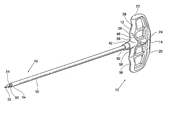
- FIG. 1 shows a composite instrument 10 for penetrating tissue.
- the composite instrument 10 includes a first functional instrument 20 and a second functional instrument 40 , and a composite handle 12 comprising a first handle 22 and a second handle 42 .
- the composite handle 12 aids a physician in manipulating the composite instrument 10 , but a physician can also desirably use the first handle 22 to independently manipulate the first instrument 20 or the second handle 42 to independently manipulate the second instrument 40 during use.
- FIG. 1 shows two representative instruments 20 and 40 , each having a different size and function.
- the first functional instrument 20 is a trocar instrument
- the second functional instrument 40 is a cannula instrument.
- the first instrument 20 functions as a trocar instrument to penetrate tissue.
- a trocar 30 has a proximal end 32 and a distal end 34 .
- the distal end 34 is tapered to present a penetrating surface 35 .
- the penetrating surface 35 is intended to penetrate soft tissue and/or bone in response to pushing and/or twisting forces applied by the physician at the first handle 22 , or the composite handle 12 .
- the first handle 22 is coupled to the trocar 30 at the proximal end of the trocar 32 .
- the proximal end 32 of the trocar 30 can be formed in a T-shape, with the first handle 22 being molded around the T-shaped end. This arrangement significantly increases the mechanical strength of the bond between the handle 22 and the trocar 30 , and allows significant longitudinal and torsional forces to be transmitted from the handle 22 to the trocar 30 without bond failure.
- the proximal end 32 of the trocar 30 can be scored (indicated by scored region 33 in FIG. 6C) to increase the mechanical strength of the bond between the trocar 30 and the handle 22 , or various bonding adhesives could be used, with varying results.
- the first handle 22 desirably includes a viewing window 24 , an alignment ridge receiver 26 , a handle bore receiver 28 , and a handle key 36 , the uses of which are described later.
- the trocar 30 includes an interior lumen 21 , which passes through the handle 22 and the body of the trocar 30 .
- the interior lumen 21 accommodates passage of a stylet and/or conventional spinal needle assembly 23 , to guide the deployment of the first instrument 20 , by itself or nested with the second instrument 40 (as FIG. 18 shows) through soft tissue to a targeted bone treatment site.
- the second instrument 40 functions as a cannula instrument or guide sheath, and includes a cannula 50 .
- the cannula 50 of the second instrument 40 is desirably somewhat larger in diameter than and not as long as the trocar 30 of the first instrument 20 .
- the second instrument 40 includes an interior lumen 44 that extends through the instrument from its distal end 54 to its proximal end 52 .
- the interior lumen 44 is sized to accept the trocar 30 .
- the size of the interior lumen 44 desirably allows the second instrument 40 to slide and/or rotate relative to the first instrument 20 , and vice versa, as will be described in greater detail later.
- the distal end 54 of the second instrument 40 presents an end surface 60 .
- the end surface 60 of the second instrument 40 desirably presents a-low-profile surface, which can penetrate soft tissue surrounding the first instrument 20 in response to pushing and/or twisting forces applied at the composite handle 12 or the second handle 42 .
- the proximal end 52 is coupled with the second handle 42 .
- the proximal end 52 of the cannula 50 desirably incorporates a flared and notched end “A” and a textured surface “B”, around which the second handle 42 is molded.
- the flared and notched end “A” and textured surface “B” serve to increase the mechanical strength of the bond between the cannula 50 and the second handle 42 , allowing significant longitudinal and torsional forces to be transmitted between the second handle 42 and cannula 50 without bond failure.
- alternative bonding methods such as scoring of the cannula 50 and/or the use of various adhesives could be employed, with varying results.
- the second handle 42 desirably includes a handle bore 48 , preferably co-circumferential with the cannula 50 .
- the second handle 42 includes an alignment ridge 46 , and a handle groove 56 , the uses of which are described later.
- an optional third functional instrument 70 functions as a drill bit.
- the drill bit instrument 70 having a distal end 72 and a proximal end 74 , typically is slightly longer than and has generally the same physical dimensions as, the trocar 30 .
- the drill bit instrument 70 is intended, in use, to fit for sliding and rotational movement within the interior lumen 44 of the second instrument 40 .
- the distal end 72 of the drill bit instrument 70 desirably includes cutting edges 76 .
- the cutting edges 76 are intended to penetrate hard tissue in response to rotation and longitudinal load forces applied at the proximal end 74 of the drill bit instrument 70 .
- the drill bit instrument 70 can be of known construction, and could vary widely. Desirably. the diameter of the drill bit instrument 70 is smaller than the interior lumen 44 of the second instrument 40 , and the length is longer than the cannula 50 , such that the drill bit instrument 70 can access tissue deeper than the cannula 50 when the cannula 50 is installed in a patient.
- the first handle 22 and the second handle 42 are designed to comfortably accommodate a hand, to desirably interlock to form a composite handle 12 that resists relative rotation between the first handle 22 and the second handle 42 , and desirably to indicate whether the instruments have been reused and/or resterilized.
- the composite handle 12 is shaped to be comfortably and securely grasped by a normal human hand as shown in FIG. 3.
- the contours of the composite handle 12 are rounded to provide a comfortable grip and to minimize surgical glove tears.
- the first handle 22 is desirably equipped with two finger receivers 38 , intended to receive the index finger and the pinkie finger of a physician.
- the second handle 42 is desirably equipped with two finger receivers 58 , intended to receive the middle finger and the ring finger of a physician.
- the composite handle 12 and in particular the first handle 22 , includes a striking plate 14 , elongated to fit comfortably across the palm of the hand.
- the striking plate 14 is also configured to receive a striking blow, described later.
- the first handle 22 desirably will not rotate relative to the second handle 42 .
- the first handle 22 preferably includes the alignment ridge receiver 26 to receive the alignment ridge 46 of the second handle 42 .
- the alignment mechanism interaction between the first handle 22 and the second handle 42 could comprise any number of shapes other than an arcuate shape, for example a block shape or a star shape.
- the first handle 22 and second handle 44 can fit together to form the composite handle 12 .
- the first handle 22 can include a handle key 36 for coupling with the handle groove 56 of the second handle 42 .
- the handle bore 48 of the second handle 42 desirably will not fully insert into the handle bore receiver 28 of the first handle 22 .
- the viewing window 24 will display the trocar 30 , which preferably extends past the viewing window 24 .
- the first handle 22 is desirably able to rotate independently of the second handle 42 .
- the handle groove 56 is aligned with the handle key 36 , and thus the alignment ridge 46 is aligned with the alignment ridge receiver 26 , the handle bore 48 of the second handle 42 can be fully inserted into the handle bore receiver 28 of the first handle 22 .
- the viewing window 24 displays the handle bore 48 .
- the handle bore 48 is a different color than the trocar 30 such that visualization would be simplified.
- the first handle 22 desirably does not rotate independently of the second handle 42 .
- the composite handle 10 is sized and shaped to accommodate four-fingers, two fingers each on the first handle 22 and the second handle 42 .
- first and second handles 22 and 42 could be designed to engage in non-parallel orientations, such that the first and second handles 22 and 42 would not be parallel when properly engaged to form the composite handle 10 .
- the first handle 22 could incorporate a star or hexagonal shaped opening, into which a corresponding star or hexagonal shaped second handle 42 could engage in a multiplicity of orientations.
- the material chosen for the first handle 22 and the second handle 42 desirably provides sufficient structural integrity to withstand manual manipulation and forces expected from manual striking blows.
- the first handle 22 and the second handle 42 are made from a molded or cast rigid material sufficient in strength to withstand the striking, pushing and twisting forces without significant deformation.
- first handle 22 and the second handle 42 can be roughened or otherwise textured to provide a secure gripping surfaces.
- a heat degradable material can be used to indicate, through deformation, whether a hand tool has been autoclaved.
- chemical sensitive pigments such as inks commercially available from Tempil, could be applied to the composite handle 12 to indicate, through a change of color, whether a hand tool has been chemically sterilized, for instance by use of ethylene oxide (ETO), as described in the requirements of ANSI/AAMI/ISO11135:1994 for sterilizing devices.
- ETO ethylene oxide
- various materials which change color and/or physical composition in the presence of other sterilization methods can be incorporated into hand tools to indicate sterilization.
- LUSTRANTM material which is commercially available from Bayer. As shown in FIGS. 17A and 17B, when this material is used in handle construction, the material will typically deform during heat sterilization, desirably preventing the handle groove 56 from aligning with the handle key 36 , and thus preventing the alignment ridge 46 from aligning with the alignment ridge receiver 26 . Additionally, following deformation, the handle bore 48 of the second handle 42 desirably cannot be fully inserted into the handle bore receiver 28 of the first handle 22 .
- the following describes use of the composite instrument 10 , instruments 20 , 40 , and 70 , in conjunction with a catheter component 130 , a diagnostic or therapeutic element 132 , a syringe 136 and a tamping instrument 142 as shown in FIGS. 9 - 15 in the context of treating bones. This is because these items can be advantageously used for this purpose. Still, it should be appreciated that the composite instrument 10 is not limited to use in the treatment of bones, nor limited to instruments intended to contact tissue to perform a diagnostic or therapeutic function.
- the composite handle 12 configuration associating the first handle 22 and the second handle 42 can be used in association with various other hand-held instruments.
- the composite instrument 10 , handles 12 , 22 , and 42 , and instruments 20 , 40 , 64 and 70 will now be described with regard to the treatment of human vertebra. It should be appreciated, however, their use is not limited to human vertebrae.
- the handle 18 can be used in association with hand-held instruments in the treatment of diverse human or animal bone types.
- the spinal column 80 comprises a number of uniquely shaped bones, called the vertebrae 82 , a sacrum 84 , and a coccyx 86 (also called the tail bone)
- the number of vertebrae 82 that make up the spinal column 80 depends upon the species of animal. In a human (which FIG. 7A shows), there are twenty-four vertebrae 82 , comprising seven cervical vertebrae 88 , twelve thoracic vertebrae 90 , and five lumbar vertebrae 92 .
- the spinal column 80 When viewed from the side, as FIG. 7A shows, the spinal column 80 forms an S-shaped curve.
- the curve serves to support the head, which is heavy. In four-footed animals, the curve of the spine is simpler.
- each vertebra 82 includes a vertebral body 96 , which extends on the anterior (i.e., front or chest) side of the vertebra 82 .
- the vertebral body 96 is in the shape of an oval disk.
- the vertebral body 96 includes an exterior formed from compact cortical bone 98 .
- the cortical bone 98 encloses an interior volume 100 of reticulated cancellous, or spongy, bone 102 (also called medullary bone or trabecular bone) .
- a “cushion,” called an intervertebral disk 104 is located between adjacent vertebral bodies 96 .
- An opening, called the vertebral foramen 106 is located on the posterior (i.e., back) side of each vertebra 82 .
- the spinal ganglion 109 pass through the foramen 106 .
- the spinal cord 108 passes through the spinal canal 107 .
- the vertebral arch 110 surrounds the spinal canal 107 .
- the pedicles 112 of the vertebral arch 110 adjoin the vertebral body 96 .
- the spinous process 114 extends from the posterior of the vertebral arch 110 , as do the left and right transverse processes 116 .
- a patient lies on an operating table, while the physician introduces the composite instrument 10 into soft tissue (designated S in FIG. 9) in the patient's back.
- the patient can lie face down on the table, or on either side, or at an oblique angle, depending upon the physician's preference.
- the procedure can be performed through an open anterior procedure or an endoscopic anterior procedure.
- the physician advances the composite instrument 10 through soft tissue S down to and into the targeted vertebra 82 , as FIG. 9 shows.
- the physician will typically administer a local anesthetic, for example, lidocaine, to the targeted region.
- a local anesthetic for example, lidocaine
- the physician may prefer other forms of anesthesia, such as general anesthesia.
- the physician directs the composite instrument 10 such that the trocar 30 of the first instrument 20 and the cannula 50 of the second instrument 40 penetrate the cortical bone 98 and the cancellous bone 102 of the targeted vertebra 82 .
- the physician twists the composite handle 10 while applying longitudinal force to the handle 10 .
- the penetrating surface 35 of the trocar 30 , and the end surface 60 of the cannula 50 rotate and penetrate soft tissue and/or bone.
- the depth of penetration of the distal end 34 of the trocar 30 and the end surface 60 of the cannula 50 are through a first wall of the cortical bone 98 and into the cancellous bone 102 .
- a physician can continue penetration by gently striking the striking plate 14 with a blunt instrument such as a surgical hammer (not shown), or otherwise applying appropriate additional longitudinal force to the composite handle 12 , to advance the distal end 34 of the trocar 30 and the end surface 60 of the cannula 50 .
- the physician can utilize a spinal needle assembly and stylet to initially access the vertebral body 82 , and then utilize the alternative embodiment shown in FIG. 18 to complete the access procedure.
- the embodiment shown in FIG. 18 allows the physician to place a stylet 23 into the targeted vertebral body 82 , and then guide the composite instrument 10 through soft tissue and into the targeted vertebra body 82 along the stylet 23 , which passes through the trocar lumen 21 as the composite instrument 10 is advanced through soft tissue and into the vertebral body 82 . Once the trocar 30 has sufficiently penetrated cortical bone, the physician can withdraw the spinal needle assembly 23 .
- the physician may continue advancing the composite instrument 10 through the cancellous bone 102 of the vertebral body 96 , thereby forming a passage through the cancellous bone 102 .
- this passage will extend no more than 95% across the vertebral body.
- the physician may then withdraw the instrument 10 , such that the cannula 50 remains within the cortical bone 98 and/or extends only part-way into the cancellous bone 102 .
- the trocar 30 may then be withdrawn from the cannula 50 , allowing access to the passage formed in the interior of the vertebral body 82 through the cannula 50 .
- the physician may choose to withdraw the trocar 30 from the cannula 50 and form a passage in the cancellous bone 102 using a drill bit 70 .
- the physician removes the first functional instrument 20 by holding the second instrument 40 in place and manually withdrawing the first instrument 20 .
- the physician advances the drill bit 70 through the cannula 50 .
- the physician applies appropriate twisting and longitudinal forces to the drill bit 70 , to rotate and advance the cutting edge 76 of the drill bit 70 to open a passage through the bone tissue and completely into the cancellous bone 102 .
- the drilled passage preferably extends no more than 95% across the vertebral body 96 .
- the physician can now acquire the catheter component 130 .
- the physician can advance the diagnostic or therapeutic element 132 carried by the catheter component 130 through the handle bore 48 and cannula 50 and into the interior volume 100 of the vertebral body 96 .
- the distal diagnostic or therapeutic element 132 of the catheter component 130 can be configured to perform various functions.
- the element 132 can comprise a biopsy instrument, to obtain samples of cancellous bone or to harvest bone marrow.
- the distal element 132 can be a stylet to introduce a medication or the like into cancellous bone.
- the distal element 132 can comprise an expandable body to compact cancellous bone 102 and form a cavity 134 in the vertebral body 96 , in the manner disclosed in U.S. Pat. Nos. 4,969,888, 5,108,404, and 5,827,289, which are incorporated herein by reference.
- the distal element 132 can also include a nozzle 140 to inject a material into the formed cavity.
- the physician Upon formation of the cavity 134 , the physician acquires a syringe 136 and injection nozzle 140 .
- the nozzle 140 is sized to pass through the cannula 50 , to thereby pass into the cavity 134 .
- the nozzle 140 connects by a threaded connector 186 to a syringe 136 .
- the nozzle 140 can be formed from a rigid metal material, e.g., stainless steel.
- the physician fills the syringe 136 with the desired volume of filling material 138 .
- the physician attaches the nozzle 140 to the filled syringe 136 .
- the physician inserts the nozzle 140 a selected distance beyond the distal end 54 of the cannula 50 and into the cavity, guided by markings 166 on the nozzle 140 .
- the physician operates the syringe 136 to expel the material 138 through the nozzle 140 into the cavity 134 .
- the physician first introduces the material 138 into the region of the cavity 134 farthest from the distal end 54 of the cannula 54 .
- the physician successively draws the nozzle 140 toward the distal end 54 of the cannula 50 , while injecting the material 138 , to fill the remainder of the cavity 54 .
- the nozzle 180 is unthreaded from the syringe 104 .
- the physician next advances a tamping instrument 142 through the nozzle 140 .
- the distal end of the tamping instrument 142 contacts the residual volume of material 138 in the nozzle 140 .
- Advancement of the tamping instrument 142 displaces the residual material 138 from the nozzle 140 , forcing it into the cavity 134 .
- the flow of material 138 into the cavity 134 propelled by the advancement of the tamping instrument 142 in the nozzle 140 serves to uniformly distribute and compact the material 138 inside the cavity 134 , without the application of undue pressure.
- the physician can attach the syringe 136 directly to the handle bore 48 of the second instrument 40 .
- the syringe 136 can have threads 137 or other fasteners, such as snap-sit fasteners or luer-lock fasteners. The threads 137 would match with bore threads 49 contained in the handle bore 48 .
- the physician operates the syringe 136 to expel the material 138 through the handle bore 48 and the cannula 50 and directly into the cavity 134 .
- the physician disconnects the syringe 136 and advances the tamping instrument 142 through the handle bore 48 and the cannula 50 to displace the residual material 138 from the cannula 50 , forcing it into the cavity 134 .
- low pressure i.e., desirably no greater than 360 psi at the distal end of the cannula, more desirably no greater that 190 psi at the distal end of the cannula, and most desirably no greater than 100 psi at the distal end of the cannula
- tamping instrument 142 allows the physician to respond to fill volume, flow resistance, and flow path conditions quickly. The chance of overfilling and leakage of material 138 outside the cavity portion is thereby significantly reduced.
- the physician withdraws the tamping instrument 142 from the cannula 50 and handle bore 48 .
- the physician preferably first twists the tamping instrument 142 to cleanly break contact with the material 138 .
- this procedure could be repeated to access and treat one vertebral body multiple times in multiple orientations to create multiple cavities that may or may not interconnect.
- the instruments can be withdrawn and the incision sites sutured closed. The bone treatment procedure is concluded.
- the material 138 will provide sufficient support within the vertebral body to prevent further fracture of the body. The capability of the vertebral bodies to withstand loads will have thereby been improved. The material may also facilitate healing of the vertebral body.
- the selected material 138 can be a bone cement, or autograft or allograft bone graft tissue collected in conventional ways, e.g., in paste form (see Dick, “A Use of the Acetabular Reamer to Harvest Autogenic Bone Graft Material: A Simple Method for Producing Bone Paste,” Archives of Orthopaedic and Traumatic Surgery (1986), 105: 235-238), or in pellet form (see Bhan et al, “A Percutaneous Bone Grafting for Nonunion and Delayed Union of Fractures of the Tibial Shaft,” International Orthopaedics (SICOT) (1993) 17: 310-312).
- paste form see Dick, “A Use of the Acetabular Reamer to Harvest Autogenic Bone Graft Material: A Simple Method for Producing Bone Paste,” Archives of Orthopaedic and Traumatic Surgery (1986), 105: 235-238
- pellet form see Bhan et al, “A Percutaneous Bone Grafting for Nonunion and Delayed Union of Fractures of the Tibi
- the bone graft tissue can be obtained using a Bone Graft Harvester, which is commercially available from SpineTech. Using a funnel, the paste or pellet graft tissue material is loaded into the cannula 50 . The tamping instrument 142 is then advanced into the cannula 50 in the manner previously described, to displace the paste or pellet graft tissue material out of the cannula 50 and into the cavity 134 .
- the selected material 138 can also comprise a granular bone material harvested from coral, e.g., ProOsteonTM calcium carbonate granules, available from Interpore.
- the granules are loaded into the cannula 50 using a funnel and advanced into the cavity using the tamping instrument 142 .
- the selected material 138 can also comprise demineralized bone matrix suspended in glycerol (e.g., GraftonTM allograft material available from Osteotech), or SRSTM calcium phosphate cement available from Novian.
- demineralized bone matrix suspended in glycerol e.g., GraftonTM allograft material available from Osteotech
- SRSTM calcium phosphate cement available from Novian.
- the selected material 138 can also be in sheet form, e.g. CollagraftTM material made from calcium carbonate powder and collagen from bovine bone.
- the sheet can be rolled into a tube and loaded by hand into the cannula 50 .
- the tamping instrument 142 is then advanced through the cannula 50 , to push and compact the material in the cavity 134 .
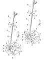
- FIGS. 19 and 20 show an alternative embodiment for a composite instrument 210 for penetrating tissue, which shares many of the features of the composite instrument 10 , previously described.
- the composite instrument 210 when disassembled, the composite instrument 210 , like the composite instrument 10 previously described, includes a first functional instrument 220 and a second functional instrument 240 .
- a composite handle 212 joins the two instruments 220 and 240 , when assembled (as FIGS. 19 and 20 show) .
- the composite handle 212 comprises a first handle 222 (associated with the first instrument 220 ) and a second handle 242 (associated with the second instrument 240 ) (as FIG. 22 also shows).
- the composite handle 212 for the instrument 210 aids a physician in manipulating the composite instrument 210 , but a physician can also desirably use the first handle 222 to independently manipulate the first instrument 220 or the second handle 242 to independently manipulate the second instrument 240 during use.
- each instrument 220 and 240 has a different size and function.
- the first functional instrument 220 is a trocar instrument
- the second functional instrument 240 is a cannula instrument.
- the first instrument 220 functions as a trocar instrument 230 to penetrate tissue.
- the trocar 230 has a proximal end 232 and a distal end 234 .
- the distal end 234 is intended to penetrate soft tissue and/or bone in response to pushing and/or twisting forces applied by the physician at the first handle 222 , or the composite handle 212 .
- the distal end 234 can terminate in a substantially blunt and/or cannulated tip, or alternatively terminate in a sharpened tip for cutting through tissue, as known in the art.
- the first handle 222 is coupled to proximal end 232 of the trocar 230 . Similar to that shown in FIG. 6C for the trocar 30 , the proximal end 232 of the trocar 230 can likewise be formed in a T-shape, with the first handle 222 being molded around the T-shaped end. As earlier described with reference to the trocar 30 , this arrangement significantly increases the mechanical strength of the bond between the handle 222 and the trocar 230 , and allows significant longitudinal and torsional forces to be transmitted from the handle 222 to the trocar 230 without bond failure.
- the proximal end 232 of the trocar 230 can be scored (as shown, in relation to the trocar 32 , by scored region 33 in FIG. 6C) to increase the mechanical strength of the bond between the trocar 230 and the handle 222 , or various bonding adhesives could be used, with varying results.
- the first handle 222 desirably includes a receiving channel 226 with a viewing window 224 and a latch mechanism 236 (also shown in FIGS. 23 and 24), the structure and function of which are described later.
- the trocar 230 may include an interior lumen (not shown), which passes through the handle 222 and the body of the trocar 230 , to accommodate passage of a stylet and/or conventional spinal needle assembly, to guide the deployment of the first instrument 220 , by itself or nested with the second instrument 240 (as FIG. 18 shows with respect to the first described embodiment), through soft tissue to a targeted bone treatment site.
- the second instrument 240 functions as a cannula instrument or guide sheath, and includes a cannula 250 .
- the cannula 250 of the second instrument 240 is desirably somewhat larger in diameter than and not as long as the trocar 230 of the first instrument 220 .
- the second instrument 240 includes an interior lumen 244 that extends through the instrument from its distal end 254 to its proximal end 252 .
- the interior lumen 244 is sized to accept the trocar 230 (as FIG. 21 shows).
- the size of the interior lumen 244 desirably allows the second instrument 240 to slide and/or rotate relative to the first instrument 220 , and vice versa, unless the two handles 222 and 242 are locked together, as will be described later.
- the distal end 254 of the second instrument 240 presents an end surface that desirably presents a low-profile surface, which can penetrate soft tissue surrounding the first instrument 220 in response to pushing and/or twisting forces applied at the composite handle 212 or the second handle 242 .
- the proximal end 252 is coupled with the second handle 242 .
- the proximal end 252 of the cannula 250 can desirably incorporate a flared and notched end “A” and/or a textured surface “B”, around which the second handle 242 is molded.
- the flared and notched end “A” and/or textured surface “B” serve to increase the mechanical strength of the bond between the cannula 250 and the second handle 242 , allowing significant longitudinal and torsional forces to be transmitted between the second handle 242 and cannula 250 without bond failure.
- other bonding methods such as scoring of the cannula 250 and/or the use of various adhesives could be employed, with varying results.
- the second handle 242 desirably includes a handle bore 248 , preferably co-circumferential with the cannula 250 .
- the second handle 242 includes a transverse shoulder 246 and at least one latch notch 256 on the shoulder 246 , the structure and function of which are described later.
- the first handle 222 and the second handle 242 are designed to comfortably accommodate a hand, to desirably interlock to form a composite handle 212 that resists relative rotation between the first handle 222 and the second handle 242 .
- the composite handle 212 is shaped to be comfortably and securely grasped by a normal human hand, as generally shown in FIG. 21.
- the contours of the composite handle 212 are likewise rounded to provide a comfortable grip and to minimize surgical glove tears.
- the first handle 222 is desirably equipped with two finger receivers 238 , intended to receive the index finger and the pinkie finger of a physician, in the same fashion shown for the handle 12 in FIG. 3.
- the second handle 242 is desirably equipped with two finger receivers 258 , intended to receive the middle finger and the ring finger of a physician, in the same fashion shown for the handle 42 in FIG. 4.
- first handle 222 and second handle 242 vary.
- the composite handle 212 and in particular the first handle 222 , includes a striking plate 214 , elongated to fit comfortably across the palm of the hand.
- the striking plate 214 is also configured to receive a striking blow, for the purposes described above.
- the material chosen for the first handle 222 and the second handle 242 desirably provides sufficient structural integrity to withstand manual manipulation and forces expected from manual striking blows.
- the first handle 222 and the second handle 242 are made from a molded or cast rigid material sufficient in strength to withstand the striking, pushing and twisting forces without significant deformation.
- Representative materials for the first and second handles 222 and 242 can include various plastics, metals, and/or ceramics well known in the art.
- the first and second handles 222 and 242 are formed from Lustran® ABS (acrylonitrile-butadiene-styrene) plastic, available commercially from Bayer Corporation.
- first handle 222 and the second handle 242 can be roughened or otherwise textured to provide a secure gripping surfaces.
- the first handle 222 desirably will not rotate relative to the second handle 242 when the two handles 222 and 242 are secured together.
- the first handle 222 preferably includes the receiving channel 226 into which the shoulder 246 of the second handle 242 is advanced and nests (see FIGS. 23 and 24)
- the first handle 222 and second handle 244 fit together to form the composite handle 212 (as FIG. 19 shows) .
- the shoulder 246 nests within the locking channel 226 , resisting rotation of the first instrument 220 relative to the second instrument 240 .
- the latch mechanism 236 on the first handle 222 engages the latch notch 256 on the second handle 242 , to resist separation of the two instruments 220 and 240 .
- the latch mechanism 236 can be constructed in various ways. As shown in FIGS. 23 and 24, the latch mechanism 236 includes a latch finger 260 situated to engage the latch notch 256 on the second handle 242 .
- the latch finger 260 is carried on a hinge 262 in the first handle 222 .
- the hinge 262 is desirably made from resilient plastic material and possesses plastic memory, forming a so-called “living hinge.”
- the latch finger 260 is cantilevered on the hinge 262 for pivoting movement within the first handle 222 .
- the plastic memory of the hinge 262 normally biases the finger 260 toward a normal position, shown in FIG. 23, in which the finger 260 will rest within the notch 256 , provided that the two parts are in alignment.
- the latch finger 260 can be displaced out of its normal position (as shown in FIG. 24) in response to an applied force F. Upon removal of the force F, the hinge 262 returns the finger 260 to its normal position.
- the force F is applied in at least two different ways.
- the latch finger 260 includes a cam surface 264 (best shown in FIG. 24).
- the leading edge 266 of the locking shoulder 246 slides or rides along the cam surface 264 as the shoulder 246 progresses through the channel 226 . Progressive advancement of the leading edge 266 of the shoulder 246 along the cam surface 264 will apply the force F, to cause the latch finger 260 to pivot on the hinge 262 .
- the locking notch 256 on the shoulder 246 is in mutual alignment with the latch finger 260 , the force F is relieved, and the latch finger 260 resiliently returns toward its normal position. This moves the latch finger 260 into the notch 256 , in a snap-fit.
- the plastic memory of the hinge resists movement of the notch 256 out of engagement with the latch finger 260 , effectively locking the two handles 222 and 242 together as the composite handle 212 .
- the shoulder 246 desirably includes a locking notch 256 on reverse facing, opposite sides of the shoulder 246 . In this way, the fitment of the shoulder 246 into the channel 226 is not sensitive to mutual orientation of the two handles 222 and 242 .
- the viewing window 224 on the first handle 222 reveals the advancement of the shoulder 246 through the channel 226 and into engagement with the latching mechanism 236 .
- This provides visual confirmation of the locking fit.
- the shoulder 246 is a different color than first handle 220 , such that visualization would be further simplified.
- the composite handle 210 is sized and shaped to accommodate four fingers, two fingers each on the first handle 222 and the second handle 242 , in the same fashion shown for the composite handle 10 in FIG. 3.
- the latch mechanism 236 also includes a detent surface 268 . Pressing against the detent surface 268 applies the force F to the latch finger 260 , causing the finger 260 to pivot on the hinge 262 .
- the latch mechanism 236 also desirably incorporates a stop 280 , which limits the displacement of the latch mechanism during release. The force F frees the finger 260 from the notch 256 , to allow the shoulder 246 to be withdrawn from the channel 226 . The operator can thereby separate the two handles 222 and 224 (as FIG. 21 shows).
- the composite instrument 210 and the instruments 220 and 240 can be used in conjunction with a catheter element 130 , a diagnostic or therapeutic element 132 , and other instruments in the same fashion as the composite instrument 10 , previously described.
- the disclosed composite instrument 210 also greatly facilitates manipulation and use of the instrument by a physician wearing leaded and/or lead-lined gloves during the surgical procedure. Because many procedures are performed under fluoroscopic visualization, physicians repeatedly performing these procedures often wear leaded gloves to minimize exposure of their hands to harmful radiation. Such gloves are often thick, uncomfortable, and incorporate radiopaque materials, such as lead, and typically negatively impact the ability of the surgeon to manipulate small objects or to “feel” the surgical instruments during the procedure. With the disclosed composite instrument 210 , the physician can hold the instrument in a single hand, and can use a single finger to depress the detent surface 268 to separate the two handles 222 and 242 .
- the detent surface 268 is desirably sized such that it can be easily felt and manipulated, even through leaded gloves.
- the stop 280 desirably limits the displacement of the latch mechanism 236 during release, the latch mechanism 236 can withstand a significant amount of force F without damage to the hinge 262 . This is especially important where the physician is wearing leaded gloves, because the physician may not be able to accurately gage the amount of force he or she is imparting to a given tool. Even where the physician uses an excessive amount of force to release the instrument, therefore, the disclosed composite instrument 210 is less likely to fail during the surgical procedure.
Abstract
Description
- This application is a divisional of copending U.S. patent application Ser. No. 09/695,566, filed Oct. 24, 2000, and entitled “Hand-Held Instruments that Access Interior Body Regions,” which is a continuation-in-part of U.S. patent application Ser. No. 09/421,635, filed Oct. 19, 1999, and entitled “Hand-Held Instruments that Access Interior Body Regions,” both of which are incorporated herein by reference.
- The invention generally relates to hand-held tools and instruments and to procedures that deploy these instruments through tissue to access interior regions of the body.
- There are many different types and styles of handheld surgical instruments that physicians use to gain access into interior body regions. These instruments are intended to penetrate tissue by the application of pushing forces, twisting forces, or both in combination.
- Often, a single surgical procedure will require the physician to employ different surgical instruments, each possessing a different shape, size, and function. Often, the procedure will require the physician to deploy these instruments in both soft and hard tissue to meet the diagnostic or therapeutic objectives of the procedure. The physician will often need an enhanced mechanical advantage to advance an instrument through tissue, particularly through dense or hard tissue, such as bone.
- The common need to use different instruments in a given procedure, coupled with the need to accurately and reliably deploy each of these different instruments through both soft and hard tissue, often with an enhanced mechanical advantage, complicate the physician's already difficult task. The need to handle different instruments in different ways for different purposes can distract the physician and lead to wasted effort, which can lengthen the overall time of the procedure.
- The invention provides a surgical instrument with a handle design that allows initial placement of both a cannula and a trocar into interior body regions, and allows for later withdrawal of the trocar while leaving the cannula in place. The invention obviates the need for several instruments during surgical procedures, and simplifies interior access protocol. At the same time, the handle of the surgical instrument makes possible the reliable transmission, with increased mechanical advantage, of both torsional and longitudinal loads by the physician to the selected instrument.
- These and other objects of the invention are provided in a tool. The tool comprises a trocar and cannula. The trocar includes a handle. A lumen extends through the trocar and the trocar handle and accommodates passage of a functional instrument. The cannula includes a cannula handle and is sized and configured to accommodate passage of the trocar. The trocar engages the cannula to form a composite instrument. The trocar handle mates with the cannula handle to form a composite handle when the trocar is engaged with the cannula. In one embodiment, the trocar is longer than the cannula.
- In one embodiment, the functional instrument is a stylet. In another embodiment, the functional instrument is a guidewire. In yet another embodiment, the functional instrument is a spinal needle assembly.
- According to another aspect of the invention, the trocar handle includes a first distal finger gripping surface and a first proximal finger gripping surface and the cannula handle includes a second distal finger gripping surface and a second proximal finger gripping surface. The first distal gripping surface and the second distal gripping surface fit together to form a composite finger gripping surface that includes the first distal gripping surface and the second distal gripping surface when the trocar handle and the cannula handle are engaged to form the composite handle.
- The composite handle can be adapted, in use, to transmit longitudinal force, rotational force, or both longitudinal and rotational forces to the composite instrument.
- According to another aspect of the invention, the composite handle is adapted, in use, to receive a striking force. According to another aspect of the invention, the composite handle is constructed of material capable of resisting deformation when a striking force is applied.
- Another aspect of the invention provides a method of manipulating an instrument that, in use, accesses bone. The method provides a guide instrument adapted for insertion through soft tissue to a target bone treatment site. A trocar is provided including a first handle and having a lumen extending through the trocar and the handle accommodating passage of the guide instrument. A cannula is also provided including a handle and is sized and configured to accommodate passage of the trocar. The trocar engages the cannula to form a composite instrument and the trocar handle mates with the cannula handle to form a composite handle when the trocar engages the cannula. The trocar is passed through the cannula to engage the trocar with the cannula to form the composite instrument and the trocar handle is mated with the cannula handle to form the composite handle. The composite instrument is passed over the guide instrument and the composite instrument is manipulated over the guide instrument to the targeted bone treatment site.
- Features and advantages of the inventions are set forth in the following Description and Drawings, as well as in the appended claims.
- FIG. 1 is a perspective view of a first functional instrument engaging a second functional instrument to form a composite tool having a composite handle that the handles of the first and second instruments form.
- FIG. 2 is a perspective view of the first instrument separated from the second instrument.
- FIG. 3 is a perspective view of a hand engaging the composite handle of the tool shown in FIG. 1.
- FIG. 4 is a perspective view of a hand engaging the handle of the second functional instrument when separated from the first functional instrument.
- FIG. 5 is an enlarged perspective view of the handles of the first and second functional instruments, when separated, showing a coupling system than resists relative rotation between the functional instrument when the composite tool is formed.
- FIG. 6A is an enlarged side view of the handles shown in FIG. 5, when separated.
- FIG. 6B is an enlarged side view of the handles shown in FIG. 5, when mated together to form the composite handle.
- FIG. 6C is a side view of a trocar suited for use with the composite handle of FIG. 6B.
- FIG. 6D is a side view of a cannula suited for use with the composite handle of FIG. 6B.
- FIG. 7A is a lateral view of a human spinal column.
- FIG. 7B is a coronal view, with portions broken away and in section, of a human vertebral body, which is part of the spinal column.
- FIG. 8 is a lateral view, with portions broken away and in section, of several vertebral bodies, which are part of the spinal column.
- FIG. 9 is a perspective view showing advancement of the composite instrument through tissue, by using the composite handle to supply a twisting and/or pushing force.
- FIG. 10 is a top view showing deployment of the composite instrument in a vertebral body, by using the composite handle to apply an axial and/or torsional force.
- FIG. 11 is a top view of the vertebral body, showing deployment of a drill bit through a cannula instrument, which forms a part of the composite tool shown in FIG. 9.
- FIG. 12 is a top view of the vertebral body showing deployment of an expandable structure in a collapsed condition through the cannula instrument that forms a part of the composite tool shown in FIG. 9.
- FIG. 13 is a top view of the vertebral body after the structure shown in FIG. 12 is expanded to compact cancellous bone and form a cavity.
- FIG. 14 is a top view of a syringe and attached nozzle in use to inject material into the cannula instrument for passage into the cavity shown in FIG. 13.
- FIG. 15 is a side view showing advancement of a tamping instrument in the cannula instrument to displace and distribute material from the cannula instrument into the cavity shown in FIG. 13.
- FIG. 16 is a side view of a syringe attached to the cannula instrument that forms a part of the composite tool shown in FIG. 9, for the purpose of conveying material through the cannula instrument into bone.
- FIGS. 17A and 17B are perspective views showing material deformation that occurs in each handle as a result of heat sterilization, to prevent subsequent formation of the composite handle.
- FIG. 18 a perspective view of an alternative embodiment of a composite tool like that shown in FIG. 1, with an interior lumen to accommodate passage of a spinal needle assembly to aid deployment.
- FIG. 19 is a front perspective view of another embodiment of a composite tool formed by a first functional instrument engaging a second functional instrument, and also having a composite handle that the handles of the first and second instruments form.
- FIG. 20 is a rear elevation view of the composite tool shown in FIG. 19.
- FIG. 21 is a perspective view of the composite tool shown in FIG. 10, as the first and second instruments are being separated.
- FIG. 22 is a perspective view of the first instrument separated from the second instrument.
- FIG. 23 is a section view of the latching mechanism for the composite tool, taken generally along line 23-23 in FIG. 20.
- FIG. 24 is a section view of the latching mechanism shown in FIG. 23, with the associated latch finger moved out of its normal latching position by the application of an external force.
- The invention may be embodied in several forms without departing from its spirit or essential characteristics. The scope of the invention is defined in the appended claims, rather than in the specific description preceding them. All embodiments that fall within the meaning and range of equivalency of the claims are therefore intended to be embraced by the claims.
- This Specification describes new instruments for penetrating tissue. This specification also describes systems and methods to treat bones using expandable bodies in conjunction with new instruments for penetrating tissue.
- The use of expandable bodies to treat bones is generally disclosed in U.S. Pat. Nos. 4,969,888 and 5,108,404, which are incorporated herein by reference. Improvements in this regard are disclosed in U.S. patent application, Ser. No. 08/188,224, filed Jan. 26, 1994; U.S. patent application Ser. No. 08/485,394, filed Jun. 7, 1995; and U.S. patent application Ser. No. 08/659,678, filed Jun. 5, 1996, which are each incorporated herein by reference.
- The new instruments, systems and methods will be described with regard to the treatment of vertebral bodies. It should be appreciated, however, that the handle configuration, instruments, systems and methods so described are not limited in their application to vertebrae. The systems and methods are applicable to the treatment of diverse bone types. Additionally, the handle configuration could be used with instruments other than a trocar and a cannula.
- I. The Instruments
- FIG. 1 shows a
composite instrument 10 for penetrating tissue. Thecomposite instrument 10 includes a firstfunctional instrument 20 and a secondfunctional instrument 40, and acomposite handle 12 comprising afirst handle 22 and asecond handle 42. Thecomposite handle 12 aids a physician in manipulating thecomposite instrument 10, but a physician can also desirably use thefirst handle 22 to independently manipulate thefirst instrument 20 or thesecond handle 42 to independently manipulate thesecond instrument 40 during use. - The number and type of
instruments representative instruments functional instrument 20 is a trocar instrument, and the secondfunctional instrument 40 is a cannula instrument. - A. The Trocar Instrument
- Referring to FIGS. 1-4, the
first instrument 20 functions as a trocar instrument to penetrate tissue. Atrocar 30 has aproximal end 32 and adistal end 34. Thedistal end 34 is tapered to present a penetratingsurface 35. In use, the penetratingsurface 35 is intended to penetrate soft tissue and/or bone in response to pushing and/or twisting forces applied by the physician at thefirst handle 22, or thecomposite handle 12. - The
first handle 22 is coupled to thetrocar 30 at the proximal end of thetrocar 32. As best seen in FIG. 6C, theproximal end 32 of thetrocar 30 can be formed in a T-shape, with thefirst handle 22 being molded around the T-shaped end. This arrangement significantly increases the mechanical strength of the bond between thehandle 22 and thetrocar 30, and allows significant longitudinal and torsional forces to be transmitted from thehandle 22 to thetrocar 30 without bond failure. Alternatively, with or without a T-shaped end, theproximal end 32 of thetrocar 30 can be scored (indicated by scoredregion 33 in FIG. 6C) to increase the mechanical strength of the bond between thetrocar 30 and thehandle 22, or various bonding adhesives could be used, with varying results. - The
first handle 22 desirably includes aviewing window 24, analignment ridge receiver 26, ahandle bore receiver 28, and ahandle key 36, the uses of which are described later. - In an alternative embodiment (see FIG. 18), the
trocar 30 includes aninterior lumen 21, which passes through thehandle 22 and the body of thetrocar 30. Theinterior lumen 21 accommodates passage of a stylet and/or conventionalspinal needle assembly 23, to guide the deployment of thefirst instrument 20, by itself or nested with the second instrument 40 (as FIG. 18 shows) through soft tissue to a targeted bone treatment site. - B. The Cannula Instrument
- The
second instrument 40 functions as a cannula instrument or guide sheath, and includes acannula 50. Thecannula 50 of thesecond instrument 40 is desirably somewhat larger in diameter than and not as long as thetrocar 30 of thefirst instrument 20. As best shown in FIGS. 1 and 2, thesecond instrument 40 includes aninterior lumen 44 that extends through the instrument from itsdistal end 54 to itsproximal end 52. Theinterior lumen 44 is sized to accept thetrocar 30. The size of theinterior lumen 44 desirably allows thesecond instrument 40 to slide and/or rotate relative to thefirst instrument 20, and vice versa, as will be described in greater detail later. - The
distal end 54 of thesecond instrument 40 presents anend surface 60. In use, theend surface 60 of thesecond instrument 40 desirably presents a-low-profile surface, which can penetrate soft tissue surrounding thefirst instrument 20 in response to pushing and/or twisting forces applied at thecomposite handle 12 or thesecond handle 42. - The
proximal end 52 is coupled with thesecond handle 42. As best seen in FIG. 6D, theproximal end 52 of thecannula 50 desirably incorporates a flared and notched end “A” and a textured surface “B”, around which thesecond handle 42 is molded. The flared and notched end “A” and textured surface “B” serve to increase the mechanical strength of the bond between thecannula 50 and thesecond handle 42, allowing significant longitudinal and torsional forces to be transmitted between thesecond handle 42 andcannula 50 without bond failure. As with thetrocar 30, however, alternative bonding methods such as scoring of thecannula 50 and/or the use of various adhesives could be employed, with varying results. - Extending from the
interior lumen 44 at theproximal end 52 of thecannula 50, thesecond handle 42 desirably includes a handle bore 48, preferably co-circumferential with thecannula 50. Thesecond handle 42 includes analignment ridge 46, and ahandle groove 56, the uses of which are described later. - C. The Drill Bit Instrument
- As shown in FIG. 11, an optional third
functional instrument 70 functions as a drill bit. Thedrill bit instrument 70, having adistal end 72 and aproximal end 74, typically is slightly longer than and has generally the same physical dimensions as, thetrocar 30. Like thetrocar 30, thedrill bit instrument 70 is intended, in use, to fit for sliding and rotational movement within theinterior lumen 44 of thesecond instrument 40. - The
distal end 72 of thedrill bit instrument 70 desirably includes cutting edges 76. In use, the cutting edges 76 are intended to penetrate hard tissue in response to rotation and longitudinal load forces applied at theproximal end 74 of thedrill bit instrument 70. - The
drill bit instrument 70 can be of known construction, and could vary widely. Desirably. the diameter of thedrill bit instrument 70 is smaller than theinterior lumen 44 of thesecond instrument 40, and the length is longer than thecannula 50, such that thedrill bit instrument 70 can access tissue deeper than thecannula 50 when thecannula 50 is installed in a patient. - II. The Instrument Handles
- The
first handle 22 and thesecond handle 42 are designed to comfortably accommodate a hand, to desirably interlock to form acomposite handle 12 that resists relative rotation between thefirst handle 22 and thesecond handle 42, and desirably to indicate whether the instruments have been reused and/or resterilized. - A. Hand Accommodation
- As shown in FIGS. 1-4, the
composite handle 12 is shaped to be comfortably and securely grasped by a normal human hand as shown in FIG. 3. Preferably, the contours of thecomposite handle 12 are rounded to provide a comfortable grip and to minimize surgical glove tears. - As shown in FIG. 3, in the preferred embodiment, the
first handle 22 is desirably equipped with twofinger receivers 38, intended to receive the index finger and the pinkie finger of a physician. - Shown in FIG. 4, in the preferred embodiment, the
second handle 42 is desirably equipped with twofinger receivers 58, intended to receive the middle finger and the ring finger of a physician. - The shape and size of the
first handle 22 andsecond handle 42, of course, vary. In the embodiment shown in FIG. 1, thecomposite handle 12, and in particular thefirst handle 22, includes astriking plate 14, elongated to fit comfortably across the palm of the hand. Thestriking plate 14 is also configured to receive a striking blow, described later. - B. Interlocking Configuration
- In order to properly interact when applying striking, pushing and/or twisting forces to the
composite handle 12, thefirst handle 22 desirably will not rotate relative to thesecond handle 42. Referring now to FIGS. 5, 6A and 6B, to avoid relative rotation, thefirst handle 22 preferably includes thealignment ridge receiver 26 to receive thealignment ridge 46 of thesecond handle 42. Although described and pictured as a ridge, the alignment mechanism interaction between thefirst handle 22 and thesecond handle 42 could comprise any number of shapes other than an arcuate shape, for example a block shape or a star shape. - In use, when the
trocar 30 of thefirst instrument 20 is slid through thecannula 50 of thesecond instrument 40, thefirst handle 22 andsecond handle 44 can fit together to form thecomposite handle 12. In addition to thealignment ridge 46 resisting rotation because of thealignment ridge receiver 26, thefirst handle 22 can include ahandle key 36 for coupling with thehandle groove 56 of thesecond handle 42. - If the
handle groove 56 is not aligned with thehandle key 36, and thus thealignment ridge 46 not aligned with thealignment ridge receiver 26, the handle bore 48 of thesecond handle 42 desirably will not fully insert into the handle borereceiver 28 of thefirst handle 22. In this alignment, theviewing window 24 will display thetrocar 30, which preferably extends past theviewing window 24. Also in this alignment, thefirst handle 22 is desirably able to rotate independently of thesecond handle 42. - If, however, as shown in FIG. 6B, the
handle groove 56 is aligned with thehandle key 36, and thus thealignment ridge 46 is aligned with thealignment ridge receiver 26, the handle bore 48 of thesecond handle 42 can be fully inserted into the handle borereceiver 28 of thefirst handle 22. - In this operational alignment, the
viewing window 24 displays the handle bore 48. Preferably, the handle bore 48 is a different color than thetrocar 30 such that visualization would be simplified. Also in this alignment, thefirst handle 22 desirably does not rotate independently of thesecond handle 42. In this alignment, thecomposite handle 10 is sized and shaped to accommodate four-fingers, two fingers each on thefirst handle 22 and thesecond handle 42. - Of course, its should be understood that the first and
second handles second handles composite handle 10. For example, thefirst handle 22 could incorporate a star or hexagonal shaped opening, into which a corresponding star or hexagonal shaped second handle 42 could engage in a multiplicity of orientations. - In use, various forces resist relative motion between the
first instrument 20 and thesecond instrument 40. As shown in FIG. 3, when a hand grips thecomposite handle 10, the upward force supplied by the fingers, coupled with the downward force supplied by the palm, will compress thefirst instrument 20 and thesecond instrument 40 together. As previously noted, when properly configured, relative rotation of the instruments is desirably constrained as well. - C. Handle Materials
- 1. Structural Integrity
- The material chosen for the
first handle 22 and thesecond handle 42 desirably provides sufficient structural integrity to withstand manual manipulation and forces expected from manual striking blows. Thefirst handle 22 and thesecond handle 42 are made from a molded or cast rigid material sufficient in strength to withstand the striking, pushing and twisting forces without significant deformation. - Another preferable characteristic of the handle composition is that the
first handle 22 and thesecond handle 42 can be roughened or otherwise textured to provide a secure gripping surfaces. - 2. Reuse
- To encourage single use and discourage reuse and/or resterilization, it is preferable to differentiate between new hand tools and hand tools that have been reused and/or resterilized.
- Striking and exertion of manual pressure on any of the instruments and structures described herein during first use generates stress on the material or materials which make up the instruments and/or structure. The material stress created by operational loads during first use can significantly alter the molded morphology of the structure, making future performance of the structure unpredictable.
- For example, during advancement of the trocar and the cannula into the cancellous bone during a single use creates contact with surrounding cortical and cancellous bone. This contact can damage the structure, creating localized regions of weakness, which often can escape visual detection. The existence of localized regions of weakness can unpredictably cause structural failure during a subsequent use. Such contact can also cause flattening and/or curling of the end surface of the cannula, or dulling of the penetrating surface of the trocar.
- In addition, exposure to blood and tissue during a single use can entrap biological components on or within the structure of the cannula or handles. Despite cleaning and subsequent sterilization, the presence of entrapped biological components can lead to unacceptable pyrogenic reactions.
- As a result, following first use, the structure might not meet established performance and sterilization specifications. The effects of material stress and damage caused during a single use, coupled with the possibility of pyrogen reactions even after resterilization, reasonably justify and encourage single use for the instruments and handles that are deployed in tissue and bone.
- To protect patients from the potential adverse consequences occasioned by multiple use, which include disease transmission, or material stress and instability, or decreased or unpredictable performance, various materials may be used to indicate and possibly prevent re-use and /or resterilization of the hand tools.
- For example, a heat degradable material can be used to indicate, through deformation, whether a hand tool has been autoclaved. Additionally, chemical sensitive pigments, such as inks commercially available from Tempil, could be applied to the
composite handle 12 to indicate, through a change of color, whether a hand tool has been chemically sterilized, for instance by use of ethylene oxide (ETO), as described in the requirements of ANSI/AAMI/ISO11135:1994 for sterilizing devices. In addition, various materials which change color and/or physical composition in the presence of other sterilization methods, such as radiation sterilization, can be incorporated into hand tools to indicate sterilization. - One material that provides sufficient structural rigidity and yet indicates whether an instrument has been exposed to heat common to sterilization is LUSTRAN™ material, which is commercially available from Bayer. As shown in FIGS. 17A and 17B, when this material is used in handle construction, the material will typically deform during heat sterilization, desirably preventing the
handle groove 56 from aligning with thehandle key 36, and thus preventing thealignment ridge 46 from aligning with thealignment ridge receiver 26. Additionally, following deformation, the handle bore 48 of thesecond handle 42 desirably cannot be fully inserted into the handle borereceiver 28 of thefirst handle 22. - III. ILLUSTRATIVE USE OF THE SYSTEM
- The following describes use of the
composite instrument 10,instruments catheter component 130, a diagnostic ortherapeutic element 132, asyringe 136 and a tampinginstrument 142 as shown in FIGS. 9-15 in the context of treating bones. This is because these items can be advantageously used for this purpose. Still, it should be appreciated that thecomposite instrument 10 is not limited to use in the treatment of bones, nor limited to instruments intended to contact tissue to perform a diagnostic or therapeutic function. Thecomposite handle 12 configuration associating thefirst handle 22 and thesecond handle 42 can be used in association with various other hand-held instruments. - The
composite instrument 10, handles 12, 22, and 42, andinstruments - A. Vertebral Anatomy
- One use of the system is to treat vertebral bodies. As FIG. 7A shows, the
spinal column 80 comprises a number of uniquely shaped bones, called thevertebrae 82, asacrum 84, and a coccyx 86 (also called the tail bone) The number ofvertebrae 82 that make up thespinal column 80 depends upon the species of animal. In a human (which FIG. 7A shows), there are twenty-fourvertebrae 82, comprising sevencervical vertebrae 88, twelvethoracic vertebrae 90, and fivelumbar vertebrae 92. - When viewed from the side, as FIG. 7A shows, the
spinal column 80 forms an S-shaped curve. The curve serves to support the head, which is heavy. In four-footed animals, the curve of the spine is simpler. - As FIGS. 7A, 7B and 8 show, each
vertebra 82 includes avertebral body 96, which extends on the anterior (i.e., front or chest) side of thevertebra 82. As FIGS. 7A, 7B and 8 show, thevertebral body 96 is in the shape of an oval disk. As FIGS. 7B and 8 show, thevertebral body 96 includes an exterior formed from compactcortical bone 98. Thecortical bone 98 encloses aninterior volume 100 of reticulated cancellous, or spongy, bone 102 (also called medullary bone or trabecular bone) . A “cushion,” called anintervertebral disk 104, is located between adjacentvertebral bodies 96. - An opening, called the
vertebral foramen 106, is located on the posterior (i.e., back) side of eachvertebra 82. Thespinal ganglion 109 pass through theforamen 106. Thespinal cord 108 passes through thespinal canal 107. - The
vertebral arch 110 surrounds thespinal canal 107. Thepedicles 112 of thevertebral arch 110 adjoin thevertebral body 96. Thespinous process 114 extends from the posterior of thevertebral arch 110, as do the left and righttransverse processes 116. - B. Surgical Technique
- In a typical procedure, a patient lies on an operating table, while the physician introduces the
composite instrument 10 into soft tissue (designated S in FIG. 9) in the patient's back. The patient can lie face down on the table, or on either side, or at an oblique angle, depending upon the physician's preference. Moreover, the procedure can be performed through an open anterior procedure or an endoscopic anterior procedure. - 1. Accessing Cancellous Bone
- Under radiologic or CT monitoring, the physician advances the
composite instrument 10 through soft tissue S down to and into the targetedvertebra 82, as FIG. 9 shows. The physician will typically administer a local anesthetic, for example, lidocaine, to the targeted region. In some cases, the physician may prefer other forms of anesthesia, such as general anesthesia. - As shown in FIG. 10, the physician directs the
composite instrument 10 such that thetrocar 30 of thefirst instrument 20 and thecannula 50 of thesecond instrument 40 penetrate thecortical bone 98 and thecancellous bone 102 of the targetedvertebra 82. If desired, the physician twists thecomposite handle 10 while applying longitudinal force to thehandle 10. In response, the penetratingsurface 35 of thetrocar 30, and theend surface 60 of thecannula 50 rotate and penetrate soft tissue and/or bone. - Preferably the depth of penetration of the
distal end 34 of thetrocar 30 and theend surface 60 of thecannula 50 are through a first wall of thecortical bone 98 and into thecancellous bone 102. However, if the penetration through the first wall of thecortical bone 98 and into thecancellous bone 102 is not achievable by manual advancement of thecomposite instrument 10, a physician can continue penetration by gently striking thestriking plate 14 with a blunt instrument such as a surgical hammer (not shown), or otherwise applying appropriate additional longitudinal force to thecomposite handle 12, to advance thedistal end 34 of thetrocar 30 and theend surface 60 of thecannula 50. - If desired, the physician can utilize a spinal needle assembly and stylet to initially access the
vertebral body 82, and then utilize the alternative embodiment shown in FIG. 18 to complete the access procedure. The embodiment shown in FIG. 18 allows the physician to place astylet 23 into the targetedvertebral body 82, and then guide thecomposite instrument 10 through soft tissue and into the targetedvertebra body 82 along thestylet 23, which passes through thetrocar lumen 21 as thecomposite instrument 10 is advanced through soft tissue and into thevertebral body 82. Once thetrocar 30 has sufficiently penetrated cortical bone, the physician can withdraw thespinal needle assembly 23. - After penetrating the
cortical bone 98, if desired, the physician may continue advancing thecomposite instrument 10 through thecancellous bone 102 of thevertebral body 96, thereby forming a passage through thecancellous bone 102. Preferably this passage will extend no more than 95% across the vertebral body. The physician may then withdraw theinstrument 10, such that thecannula 50 remains within thecortical bone 98 and/or extends only part-way into thecancellous bone 102. Thetrocar 30 may then be withdrawn from thecannula 50, allowing access to the passage formed in the interior of thevertebral body 82 through thecannula 50. - Alternatively, after penetrating the
cortical bone 98, the physician may choose to withdraw thetrocar 30 from thecannula 50 and form a passage in thecancellous bone 102 using adrill bit 70. In such a case, the physician removes the firstfunctional instrument 20 by holding thesecond instrument 40 in place and manually withdrawing thefirst instrument 20. - Next, as shown in FIG. 11, the physician advances the
drill bit 70 through thecannula 50. Under X-ray control (or using another external visualizing system), the physician applies appropriate twisting and longitudinal forces to thedrill bit 70, to rotate and advance thecutting edge 76 of thedrill bit 70 to open a passage through the bone tissue and completely into thecancellous bone 102. The drilled passage preferably extends no more than 95% across thevertebral body 96. - At this point in the procedure, access to the
cancellous bone 102 has been accomplished and theend surface 60 of thecannula 50 extends into theinterior volume 100, leaving only thecannula instrument 50 in place. - 2. Bone Treatment
- As shown in FIG. 12, the physician can now acquire the
catheter component 130. The physician can advance the diagnostic ortherapeutic element 132 carried by thecatheter component 130 through the handle bore 48 andcannula 50 and into theinterior volume 100 of thevertebral body 96. - The distal diagnostic or
therapeutic element 132 of thecatheter component 130 can be configured to perform various functions. For example, theelement 132 can comprise a biopsy instrument, to obtain samples of cancellous bone or to harvest bone marrow. Alternatively, thedistal element 132 can be a stylet to introduce a medication or the like into cancellous bone. Still alternatively (as shown in FIG. 13), thedistal element 132 can comprise an expandable body to compactcancellous bone 102 and form acavity 134 in thevertebral body 96, in the manner disclosed in U.S. Pat. Nos. 4,969,888, 5,108,404, and 5,827,289, which are incorporated herein by reference. Upon compaction ofcancellous bone 102, thedistal element 132 can also include anozzle 140 to inject a material into the formed cavity. - Upon formation of the
cavity 134, the physician acquires asyringe 136 andinjection nozzle 140. As FIG. 14 shows, thenozzle 140 is sized to pass through thecannula 50, to thereby pass into thecavity 134. Thenozzle 140 connects by a threadedconnector 186 to asyringe 136. Thenozzle 140 can be formed from a rigid metal material, e.g., stainless steel. - As FIG. 14 shows, the physician fills the
syringe 136 with the desired volume of fillingmaterial 138. The physician attaches thenozzle 140 to the filledsyringe 136. The physician inserts the nozzle 140 a selected distance beyond thedistal end 54 of thecannula 50 and into the cavity, guided bymarkings 166 on thenozzle 140. Next, the physician operates thesyringe 136 to expel the material 138 through thenozzle 140 into thecavity 134. - Desirably, the physician first introduces the material 138 into the region of the
cavity 134 farthest from thedistal end 54 of thecannula 54. The physician successively draws thenozzle 140 toward thedistal end 54 of thecannula 50, while injecting thematerial 138, to fill the remainder of thecavity 54. - At this stage, the nozzle 180 is unthreaded from the
syringe 104. As FIG. 15 shows, the physician next advances a tampinginstrument 142 through thenozzle 140. The distal end of the tampinginstrument 142 contacts the residual volume ofmaterial 138 in thenozzle 140. Advancement of the tampinginstrument 142 displaces theresidual material 138 from thenozzle 140, forcing it into thecavity 134. The flow ofmaterial 138 into thecavity 134, propelled by the advancement of the tampinginstrument 142 in thenozzle 140 serves to uniformly distribute and compact thematerial 138 inside thecavity 134, without the application of undue pressure. - As shown in FIG. 16, as an alternative to attaching the
nozzle 140 to thesyringe 136, the physician can attach thesyringe 136 directly to the handle bore 48 of thesecond instrument 40. As shown in the alternate embodiment in FIG. 16, thesyringe 136 can havethreads 137 or other fasteners, such as snap-sit fasteners or luer-lock fasteners. Thethreads 137 would match withbore threads 49 contained in the handle bore 48. Next, the physician operates thesyringe 136 to expel the material 138 through the handle bore 48 and thecannula 50 and directly into thecavity 134. In this arrangement, the physician disconnects thesyringe 136 and advances the tampinginstrument 142 through the handle bore 48 and thecannula 50 to displace theresidual material 138 from thecannula 50, forcing it into thecavity 134. - The use of the
syringe 136 with or withoutnozzle 140, and the tampinginstrument 142 allows the physician to exert precise control when filling thecavity 134 withmaterial 138. The physician can immediately adjust the volume and rate of delivery according to the particular local physiological conditions encountered. The application of low pressure (i.e., desirably no greater than 360 psi at the distal end of the cannula, more desirably no greater that 190 psi at the distal end of the cannula, and most desirably no greater than 100 psi at the distal end of the cannula), which is uniformly applied by the tampinginstrument 142, allows the physician to respond to fill volume, flow resistance, and flow path conditions quickly. The chance of overfilling and leakage ofmaterial 138 outside the cavity portion is thereby significantly reduced. - When the physician is satisfied that the
material 138 has been amply distributed inside the cavity portion, the physician withdraws the tampinginstrument 142 from thecannula 50 and handle bore 48. The physician preferably first twists the tampinginstrument 142 to cleanly break contact with thematerial 138. - Of course, this procedure could be repeated to access and treat one vertebral body multiple times in multiple orientations to create multiple cavities that may or may not interconnect. After a cavity has been filled and tamped in the above described manner, the instruments can be withdrawn and the incision sites sutured closed. The bone treatment procedure is concluded.
- C. Suggested Materials Desirably, the
material 138 will provide sufficient support within the vertebral body to prevent further fracture of the body. The capability of the vertebral bodies to withstand loads will have thereby been improved. The material may also facilitate healing of the vertebral body. - The selected
material 138 can be a bone cement, or autograft or allograft bone graft tissue collected in conventional ways, e.g., in paste form (see Dick, “A Use of the Acetabular Reamer to Harvest Autogenic Bone Graft Material: A Simple Method for Producing Bone Paste,” Archives of Orthopaedic and Traumatic Surgery (1986), 105: 235-238), or in pellet form (see Bhan et al, “A Percutaneous Bone Grafting for Nonunion and Delayed Union of Fractures of the Tibial Shaft,” International Orthopaedics (SICOT) (1993) 17: 310-312). Alternatively, the bone graft tissue can be obtained using a Bone Graft Harvester, which is commercially available from SpineTech. Using a funnel, the paste or pellet graft tissue material is loaded into thecannula 50. The tampinginstrument 142 is then advanced into thecannula 50 in the manner previously described, to displace the paste or pellet graft tissue material out of thecannula 50 and into thecavity 134. - The selected
material 138 can also comprise a granular bone material harvested from coral, e.g., ProOsteon™ calcium carbonate granules, available from Interpore. The granules are loaded into thecannula 50 using a funnel and advanced into the cavity using the tampinginstrument 142. - The selected
material 138 can also comprise demineralized bone matrix suspended in glycerol (e.g., Grafton™ allograft material available from Osteotech), or SRS™ calcium phosphate cement available from Novian. These viscous materials, like the bone cement previously described, can be loaded into thesyringe 136 and injected into the cavity directly or using thenozzle 140, which is inserted through thecannula 50 into thecavity 134. The tampinginstrument 142 is used to displace residual material from thecannula 50 into thecavity 134, as before described. - The selected
material 138 can also be in sheet form, e.g. Collagraft™ material made from calcium carbonate powder and collagen from bovine bone. The sheet can be rolled into a tube and loaded by hand into thecannula 50. The tampinginstrument 142 is then advanced through thecannula 50, to push and compact the material in thecavity 134. - IV. Interlocking Hand Held Instruments
- FIGS. 19 and 20 show an alternative embodiment for a
composite instrument 210 for penetrating tissue, which shares many of the features of thecomposite instrument 10, previously described. As FIG. 22 shows, when disassembled, thecomposite instrument 210, like thecomposite instrument 10 previously described, includes a firstfunctional instrument 220 and a secondfunctional instrument 240. Acomposite handle 212 joins the twoinstruments composite handle 212 comprises a first handle 222 (associated with the first instrument 220) and a second handle 242 (associated with the second instrument 240) (as FIG. 22 also shows). Like thecomposite handle 12 for thecomposite instrument 10, thecomposite handle 212 for theinstrument 210 aids a physician in manipulating thecomposite instrument 210, but a physician can also desirably use thefirst handle 222 to independently manipulate thefirst instrument 220 or thesecond handle 242 to independently manipulate thesecond instrument 240 during use. - As previously explained, the number and type of
instruments instrument functional instrument 220 is a trocar instrument, and the secondfunctional instrument 240 is a cannula instrument. - A. The Trocar Instrument
- Referring to FIG. 22, the
first instrument 220 functions as atrocar instrument 230 to penetrate tissue. Thetrocar 230 has aproximal end 232 and adistal end 234. Thedistal end 234 is intended to penetrate soft tissue and/or bone in response to pushing and/or twisting forces applied by the physician at thefirst handle 222, or thecomposite handle 212. If desired, thedistal end 234 can terminate in a substantially blunt and/or cannulated tip, or alternatively terminate in a sharpened tip for cutting through tissue, as known in the art. - The
first handle 222 is coupled toproximal end 232 of thetrocar 230. Similar to that shown in FIG. 6C for thetrocar 30, theproximal end 232 of thetrocar 230 can likewise be formed in a T-shape, with thefirst handle 222 being molded around the T-shaped end. As earlier described with reference to thetrocar 30, this arrangement significantly increases the mechanical strength of the bond between thehandle 222 and thetrocar 230, and allows significant longitudinal and torsional forces to be transmitted from thehandle 222 to thetrocar 230 without bond failure. Alternatively, with or without a T-shaped end, theproximal end 232 of thetrocar 230 can be scored (as shown, in relation to thetrocar 32, by scoredregion 33 in FIG. 6C) to increase the mechanical strength of the bond between thetrocar 230 and thehandle 222, or various bonding adhesives could be used, with varying results. - The
first handle 222 desirably includes a receivingchannel 226 with aviewing window 224 and a latch mechanism 236 (also shown in FIGS. 23 and 24), the structure and function of which are described later. - Like the
trocar 30, thetrocar 230 may include an interior lumen (not shown), which passes through thehandle 222 and the body of thetrocar 230, to accommodate passage of a stylet and/or conventional spinal needle assembly, to guide the deployment of thefirst instrument 220, by itself or nested with the second instrument 240 (as FIG. 18 shows with respect to the first described embodiment), through soft tissue to a targeted bone treatment site. - B. The Cannula Instrument Still referring principally to FIG. 22, the
second instrument 240 functions as a cannula instrument or guide sheath, and includes acannula 250. Thecannula 250 of thesecond instrument 240 is desirably somewhat larger in diameter than and not as long as thetrocar 230 of thefirst instrument 220. As best shown in FIG. 21, thesecond instrument 240 includes aninterior lumen 244 that extends through the instrument from itsdistal end 254 to itsproximal end 252. Theinterior lumen 244 is sized to accept the trocar 230 (as FIG. 21 shows). The size of theinterior lumen 244 desirably allows thesecond instrument 240 to slide and/or rotate relative to thefirst instrument 220, and vice versa, unless the twohandles - The
distal end 254 of thesecond instrument 240 presents an end surface that desirably presents a low-profile surface, which can penetrate soft tissue surrounding thefirst instrument 220 in response to pushing and/or twisting forces applied at thecomposite handle 212 or thesecond handle 242. - The
proximal end 252 is coupled with thesecond handle 242. As shown in FIG. 6D with respect to thecannula 50, theproximal end 252 of thecannula 250 can desirably incorporate a flared and notched end “A” and/or a textured surface “B”, around which thesecond handle 242 is molded. The flared and notched end “A” and/or textured surface “B” serve to increase the mechanical strength of the bond between thecannula 250 and thesecond handle 242, allowing significant longitudinal and torsional forces to be transmitted between thesecond handle 242 andcannula 250 without bond failure. As with thetrocar 230, however, other bonding methods such as scoring of thecannula 250 and/or the use of various adhesives could be employed, with varying results. - Extending from the
interior lumen 244 at theproximal end 252 of thecannula 250, thesecond handle 242 desirably includes ahandle bore 248, preferably co-circumferential with thecannula 250. Thesecond handle 242 includes atransverse shoulder 246 and at least onelatch notch 256 on theshoulder 246, the structure and function of which are described later. - C. The Handles
- The
first handle 222 and thesecond handle 242 are designed to comfortably accommodate a hand, to desirably interlock to form acomposite handle 212 that resists relative rotation between thefirst handle 222 and thesecond handle 242. - D. Hand Accommodation
- Like the
composite handle 12, thecomposite handle 212 is shaped to be comfortably and securely grasped by a normal human hand, as generally shown in FIG. 21. Preferably, the contours of thecomposite handle 212 are likewise rounded to provide a comfortable grip and to minimize surgical glove tears. Thefirst handle 222 is desirably equipped with twofinger receivers 238, intended to receive the index finger and the pinkie finger of a physician, in the same fashion shown for thehandle 12 in FIG. 3. - The
second handle 242 is desirably equipped with twofinger receivers 258, intended to receive the middle finger and the ring finger of a physician, in the same fashion shown for thehandle 42 in FIG. 4. - The shape and size of the
first handle 222 andsecond handle 242, of course, vary. In the embodiment shown in FIGS. 19 to 21, thecomposite handle 212, and in particular thefirst handle 222, includes astriking plate 214, elongated to fit comfortably across the palm of the hand. Thestriking plate 214 is also configured to receive a striking blow, for the purposes described above. - The material chosen for the
first handle 222 and thesecond handle 242 desirably provides sufficient structural integrity to withstand manual manipulation and forces expected from manual striking blows. Thefirst handle 222 and thesecond handle 242 are made from a molded or cast rigid material sufficient in strength to withstand the striking, pushing and twisting forces without significant deformation. Representative materials for the first andsecond handles second handles - Another preferable characteristic of the handle composition is that the
first handle 222 and thesecond handle 242 can be roughened or otherwise textured to provide a secure gripping surfaces. - E. Interlocking Configuration
- In order to properly interact when applying striking, pushing and/or twisting forces to the
composite handle 212, thefirst handle 222 desirably will not rotate relative to thesecond handle 242 when the twohandles first handle 222 preferably includes the receivingchannel 226 into which theshoulder 246 of thesecond handle 242 is advanced and nests (see FIGS. 23 and 24) - In use, when the
trocar 230 of thefirst instrument 220 is slid through thecannula 250 of the second instrument 240 (see FIG. 21), thefirst handle 222 andsecond handle 244 fit together to form the composite handle 212 (as FIG. 19 shows) . Theshoulder 246 nests within the lockingchannel 226, resisting rotation of thefirst instrument 220 relative to thesecond instrument 240. - Furthermore, when the locking
shoulder 246 is advanced a desired distance through thechannel 226, thelatch mechanism 236 on thefirst handle 222 engages thelatch notch 256 on thesecond handle 242, to resist separation of the twoinstruments - The
latch mechanism 236 can be constructed in various ways. As shown in FIGS. 23 and 24, thelatch mechanism 236 includes alatch finger 260 situated to engage thelatch notch 256 on thesecond handle 242. Thelatch finger 260 is carried on ahinge 262 in thefirst handle 222. Thehinge 262 is desirably made from resilient plastic material and possesses plastic memory, forming a so-called “living hinge.” - The
latch finger 260 is cantilevered on thehinge 262 for pivoting movement within thefirst handle 222. The plastic memory of thehinge 262 normally biases thefinger 260 toward a normal position, shown in FIG. 23, in which thefinger 260 will rest within thenotch 256, provided that the two parts are in alignment. Thelatch finger 260 can be displaced out of its normal position (as shown in FIG. 24) in response to an applied force F. Upon removal of the force F, thehinge 262 returns thefinger 260 to its normal position. - In the illustrated embodiment, the force F is applied in at least two different ways. One works in response to advancement of the
shoulder 246 through thechannel 226 toward thelatch mechanism 236. This serves to secure the twoinstruments composite instrument 210. The other works in response to manual pressure exerted by an operator upon thelatch mechanism 236. This serves to separate the twoinstruments instruments - Regarding the first mechanism, the
latch finger 260 includes a cam surface 264 (best shown in FIG. 24). Theleading edge 266 of the lockingshoulder 246 slides or rides along thecam surface 264 as theshoulder 246 progresses through thechannel 226. Progressive advancement of theleading edge 266 of theshoulder 246 along thecam surface 264 will apply the force F, to cause thelatch finger 260 to pivot on thehinge 262. When the lockingnotch 256 on theshoulder 246 is in mutual alignment with thelatch finger 260, the force F is relieved, and thelatch finger 260 resiliently returns toward its normal position. This moves thelatch finger 260 into thenotch 256, in a snap-fit. The plastic memory of the hinge resists movement of thenotch 256 out of engagement with thelatch finger 260, effectively locking the twohandles composite handle 212. - The
shoulder 246 desirably includes a lockingnotch 256 on reverse facing, opposite sides of theshoulder 246. In this way, the fitment of theshoulder 246 into thechannel 226 is not sensitive to mutual orientation of the twohandles - The
viewing window 224 on thefirst handle 222 reveals the advancement of theshoulder 246 through thechannel 226 and into engagement with thelatching mechanism 236. This provides visual confirmation of the locking fit. Preferably, theshoulder 246 is a different color thanfirst handle 220, such that visualization would be further simplified. - When formed, the
composite handle 210 is sized and shaped to accommodate four fingers, two fingers each on thefirst handle 222 and thesecond handle 242, in the same fashion shown for thecomposite handle 10 in FIG. 3. - Regarding the second mechanism for applying the force F to the
latch finger 260, thelatch mechanism 236 also includes adetent surface 268. Pressing against thedetent surface 268 applies the force F to thelatch finger 260, causing thefinger 260 to pivot on thehinge 262. Thelatch mechanism 236 also desirably incorporates astop 280, which limits the displacement of the latch mechanism during release. The force F frees thefinger 260 from thenotch 256, to allow theshoulder 246 to be withdrawn from thechannel 226. The operator can thereby separate the twohandles 222 and 224 (as FIG. 21 shows). - The
composite instrument 210 and theinstruments catheter element 130, a diagnostic ortherapeutic element 132, and other instruments in the same fashion as thecomposite instrument 10, previously described. - The disclosed
composite instrument 210 also greatly facilitates manipulation and use of the instrument by a physician wearing leaded and/or lead-lined gloves during the surgical procedure. Because many procedures are performed under fluoroscopic visualization, physicians repeatedly performing these procedures often wear leaded gloves to minimize exposure of their hands to harmful radiation. Such gloves are often thick, uncomfortable, and incorporate radiopaque materials, such as lead, and typically negatively impact the ability of the surgeon to manipulate small objects or to “feel” the surgical instruments during the procedure. With the disclosedcomposite instrument 210, the physician can hold the instrument in a single hand, and can use a single finger to depress thedetent surface 268 to separate the twohandles detent surface 268 is desirably sized such that it can be easily felt and manipulated, even through leaded gloves. - Moreover, because the
stop 280 desirably limits the displacement of thelatch mechanism 236 during release, thelatch mechanism 236 can withstand a significant amount of force F without damage to thehinge 262. This is especially important where the physician is wearing leaded gloves, because the physician may not be able to accurately gage the amount of force he or she is imparting to a given tool. Even where the physician uses an excessive amount of force to release the instrument, therefore, the disclosedcomposite instrument 210 is less likely to fail during the surgical procedure. - The features of the invention are set forth in the following claims.
Claims (15)
Priority Applications (2)
| Application Number | Priority Date | Filing Date | Title |
|---|---|---|---|
| US10/431,681 US7399306B2 (en) | 1999-10-19 | 2003-05-08 | Hand-held instruments that access interior body regions |
| US11/789,244 US20070197935A1 (en) | 1999-10-19 | 2007-04-24 | Hand-held instruments that access interior body regions |
Applications Claiming Priority (3)
| Application Number | Priority Date | Filing Date | Title |
|---|---|---|---|
| US09/421,635 US7081122B1 (en) | 1999-10-19 | 1999-10-19 | Hand-held instruments that access interior body regions |
| US09/695,566 US6575919B1 (en) | 1999-10-19 | 2000-10-24 | Hand-held instruments that access interior body regions |
| US10/431,681 US7399306B2 (en) | 1999-10-19 | 2003-05-08 | Hand-held instruments that access interior body regions |
Related Parent Applications (1)
| Application Number | Title | Priority Date | Filing Date |
|---|---|---|---|
| US09/695,566 Division US6575919B1 (en) | 1999-10-19 | 2000-10-24 | Hand-held instruments that access interior body regions |
Related Child Applications (1)
| Application Number | Title | Priority Date | Filing Date |
|---|---|---|---|
| US11/789,244 Division US20070197935A1 (en) | 1999-10-19 | 2007-04-24 | Hand-held instruments that access interior body regions |
Publications (2)
| Publication Number | Publication Date |
|---|---|
| US20030191414A1 true US20030191414A1 (en) | 2003-10-09 |
| US7399306B2 US7399306B2 (en) | 2008-07-15 |
Family
ID=24793536
Family Applications (3)
| Application Number | Title | Priority Date | Filing Date |
|---|---|---|---|
| US09/695,566 Expired - Fee Related US6575919B1 (en) | 1999-10-19 | 2000-10-24 | Hand-held instruments that access interior body regions |
| US10/431,681 Expired - Fee Related US7399306B2 (en) | 1999-10-19 | 2003-05-08 | Hand-held instruments that access interior body regions |
| US11/789,244 Abandoned US20070197935A1 (en) | 1999-10-19 | 2007-04-24 | Hand-held instruments that access interior body regions |
Family Applications Before (1)
| Application Number | Title | Priority Date | Filing Date |
|---|---|---|---|
| US09/695,566 Expired - Fee Related US6575919B1 (en) | 1999-10-19 | 2000-10-24 | Hand-held instruments that access interior body regions |
Family Applications After (1)
| Application Number | Title | Priority Date | Filing Date |
|---|---|---|---|
| US11/789,244 Abandoned US20070197935A1 (en) | 1999-10-19 | 2007-04-24 | Hand-held instruments that access interior body regions |
Country Status (12)
| Country | Link |
|---|---|
| US (3) | US6575919B1 (en) |
| EP (2) | EP1328201B1 (en) |
| JP (2) | JP3980481B2 (en) |
| KR (4) | KR20080075002A (en) |
| CN (2) | CN1319493C (en) |
| AT (1) | ATE385408T1 (en) |
| AU (1) | AU2002239469A1 (en) |
| CA (1) | CA2426699A1 (en) |
| DE (1) | DE60132705T2 (en) |
| ES (1) | ES2304400T3 (en) |
| HK (1) | HK1075193A1 (en) |
| WO (1) | WO2002041796A2 (en) |
Cited By (80)
| Publication number | Priority date | Publication date | Assignee | Title |
|---|---|---|---|---|
| US20030225344A1 (en) * | 2002-05-31 | 2003-12-04 | Vidacare Corporation | Apparatus and method to access the bone marrow for oncology and stem cell applications |
| WO2005092202A1 (en) * | 2004-03-05 | 2005-10-06 | Smith & Nephew, Inc. | Medical instrument handle |
| WO2006002343A2 (en) * | 2004-06-24 | 2006-01-05 | Bcu International | Method and medical device for rapid and accurate entry through soft tissue and bone |
| US20070010845A1 (en) * | 2005-07-08 | 2007-01-11 | Gorman Gong | Directionally controlled expandable device and methods for use |
| US20070010716A1 (en) * | 2005-07-11 | 2007-01-11 | Malandain Hugues F | Surgical access device, system, and methods of use |
| US20070006692A1 (en) * | 2005-07-11 | 2007-01-11 | Phan Christopher U | Torque limiting device |
| US20070010844A1 (en) * | 2005-07-08 | 2007-01-11 | Gorman Gong | Radiopaque expandable body and methods |
| US20070233146A1 (en) * | 2006-01-27 | 2007-10-04 | Stryker Corporation | Low pressure delivery system and method for delivering a solid and liquid mixture into a target site for medical treatment |
| US20070255282A1 (en) * | 2006-04-27 | 2007-11-01 | Sdgi Holdings, Inc. | Dilating stylet and cannula |
| US20070255281A1 (en) * | 2006-04-27 | 2007-11-01 | Sdgi Holdings, Inc. | Method for use of dilating stylet and cannula |
| US20070260227A1 (en) * | 2005-07-11 | 2007-11-08 | Phan Christopher U | Axial load limiting system and methods |
| US20080004605A1 (en) * | 2003-11-25 | 2008-01-03 | Scimed Life Systems, Inc. | Medical device with visual indicator and related methods of use |
| US20080086142A1 (en) * | 2006-10-06 | 2008-04-10 | Kohm Andrew C | Products and Methods for Delivery of Material to Bone and Other Internal Body Parts |
| US20080243249A1 (en) * | 2007-03-30 | 2008-10-02 | Kohm Andrew C | Devices for multipoint emplacement in a body part and methods of use of such devices |
| US20090036799A1 (en) * | 2007-03-30 | 2009-02-05 | Medtronic Spinal And Biologics Business | Methods and Systems For The Diagnosis and Treatment of Medical Conditions in the Spine and Other Body Parts |
| US7666227B2 (en) | 2005-08-16 | 2010-02-23 | Benvenue Medical, Inc. | Devices for limiting the movement of material introduced between layers of spinal tissue |
| WO2010105018A1 (en) * | 2009-03-13 | 2010-09-16 | Wyeth Llc | Bone cement delivery systems and related kits and methods |
| US7811260B2 (en) | 2002-05-31 | 2010-10-12 | Vidacare Corporation | Apparatus and method to inject fluids into bone marrow and other target sites |
| US7815642B2 (en) | 2004-01-26 | 2010-10-19 | Vidacare Corporation | Impact-driven intraosseous needle |
| US7850620B2 (en) | 2002-05-31 | 2010-12-14 | Vidacare Corporation | Biopsy devices and related methods |
| US7942826B1 (en) | 2005-06-06 | 2011-05-17 | Nuvasive, Inc. | Insulated pedicle access system and related methods |
| US7951089B2 (en) | 2002-05-31 | 2011-05-31 | Vidacare Corporation | Apparatus and methods to harvest bone and bone marrow |
| US8038682B2 (en) | 2004-08-17 | 2011-10-18 | Boston Scientific Scimed, Inc. | Apparatus and methods for delivering compounds into vertebrae for vertebroplasty |
| US8128632B2 (en) | 2006-05-22 | 2012-03-06 | Orthovita, Inc. | Delivery of multicomponent compositions |
| US8142365B2 (en) | 2002-05-31 | 2012-03-27 | Vidacare Corporation | Apparatus and method for accessing the bone marrow of the sternum |
| US8366773B2 (en) | 2005-08-16 | 2013-02-05 | Benvenue Medical, Inc. | Apparatus and method for treating bone |
| US8419683B2 (en) | 2004-11-12 | 2013-04-16 | Vidacare Corporation | Intraosseous device and methods for accessing bone marrow in the sternum and other target areas |
| US8454617B2 (en) | 2005-08-16 | 2013-06-04 | Benvenue Medical, Inc. | Devices for treating the spine |
| US8535327B2 (en) | 2009-03-17 | 2013-09-17 | Benvenue Medical, Inc. | Delivery apparatus for use with implantable medical devices |
| US8591583B2 (en) | 2005-08-16 | 2013-11-26 | Benvenue Medical, Inc. | Devices for treating the spine |
| US8641715B2 (en) | 2002-05-31 | 2014-02-04 | Vidacare Corporation | Manual intraosseous device |
| US8656929B2 (en) | 2002-05-31 | 2014-02-25 | Vidacare Corporation | Medical procedures trays and related methods |
| US8668698B2 (en) | 2002-05-31 | 2014-03-11 | Vidacare Corporation | Assembly for coupling powered driver with intraosseous device |
| US8690791B2 (en) | 2002-05-31 | 2014-04-08 | Vidacare Corporation | Apparatus and method to access the bone marrow |
| US8814873B2 (en) | 2011-06-24 | 2014-08-26 | Benvenue Medical, Inc. | Devices and methods for treating bone tissue |
| US8944069B2 (en) | 2006-09-12 | 2015-02-03 | Vidacare Corporation | Assemblies for coupling intraosseous (IO) devices to powered drivers |
| US8974410B2 (en) | 2006-10-30 | 2015-03-10 | Vidacare LLC | Apparatus and methods to communicate fluids and/or support intraosseous devices |
| US9072543B2 (en) | 2002-05-31 | 2015-07-07 | Vidacare LLC | Vascular access kits and methods |
| US20160030013A1 (en) * | 2014-07-30 | 2016-02-04 | Arthrex, Inc. | Bone marrow aspiration needle assembly |
| US9314228B2 (en) | 2002-05-31 | 2016-04-19 | Vidacare LLC | Apparatus and method for accessing the bone marrow |
| US9433400B2 (en) | 2004-01-26 | 2016-09-06 | Vidacare LLC | Manual intraosseous device |
| US9439667B2 (en) | 2002-05-31 | 2016-09-13 | Vidacare LLC | Apparatus and methods to install, support and/or monitor performance of intraosseous devices |
| US9451968B2 (en) | 2002-05-31 | 2016-09-27 | Vidacare LLC | Powered drivers, intraosseous devices and methods to access bone marrow |
| US9504477B2 (en) | 2003-05-30 | 2016-11-29 | Vidacare LLC | Powered driver |
| US9510910B2 (en) | 2006-09-12 | 2016-12-06 | Vidacare LLC | Medical procedures trays and related methods |
| US9545243B2 (en) | 2002-05-31 | 2017-01-17 | Vidacare LLC | Bone marrow aspiration devices and related methods |
| US9750508B1 (en) | 2009-11-11 | 2017-09-05 | Nuvasive, Inc. | Insulated pedicle access system and related methods |
| US9788963B2 (en) | 2003-02-14 | 2017-10-17 | DePuy Synthes Products, Inc. | In-situ formed intervertebral fusion device and method |
| US9999444B2 (en) | 2011-03-01 | 2018-06-19 | Orthovita, Inc. | Depth controlled Jamshidi needle |
| US10085783B2 (en) | 2013-03-14 | 2018-10-02 | Izi Medical Products, Llc | Devices and methods for treating bone tissue |
| US20190223903A1 (en) * | 2016-06-10 | 2019-07-25 | Fresenius Kabi Deutschland Gmbh | Cannulation device |
| WO2020206244A1 (en) * | 2019-04-05 | 2020-10-08 | Vanderbilt University | Systems and methods for advancing a catheter to a target site |
| US10888433B2 (en) | 2016-12-14 | 2021-01-12 | DePuy Synthes Products, Inc. | Intervertebral implant inserter and related methods |
| US20210007862A1 (en) * | 2018-02-27 | 2021-01-14 | Nextremity Solutions, Inc. | Disposable handle for medical instruments |
| US10940016B2 (en) | 2017-07-05 | 2021-03-09 | Medos International Sarl | Expandable intervertebral fusion cage |
| US10966840B2 (en) | 2010-06-24 | 2021-04-06 | DePuy Synthes Products, Inc. | Enhanced cage insertion assembly |
| US10973545B2 (en) | 2002-05-31 | 2021-04-13 | Teleflex Life Sciences Limited | Powered drivers, intraosseous devices and methods to access bone marrow |
| US10973532B2 (en) | 2002-05-31 | 2021-04-13 | Teleflex Life Sciences Limited | Powered drivers, intraosseous devices and methods to access bone marrow |
| US10973652B2 (en) | 2007-06-26 | 2021-04-13 | DePuy Synthes Products, Inc. | Highly lordosed fusion cage |
| US11273050B2 (en) | 2006-12-07 | 2022-03-15 | DePuy Synthes Products, Inc. | Intervertebral implant |
| US11298202B2 (en) | 2002-05-31 | 2022-04-12 | Teleflex Life Sciences Limited | Biopsy devices and related methods |
| US11337728B2 (en) | 2002-05-31 | 2022-05-24 | Teleflex Life Sciences Limited | Powered drivers, intraosseous devices and methods to access bone marrow |
| US11344424B2 (en) | 2017-06-14 | 2022-05-31 | Medos International Sarl | Expandable intervertebral implant and related methods |
| US11426286B2 (en) | 2020-03-06 | 2022-08-30 | Eit Emerging Implant Technologies Gmbh | Expandable intervertebral implant |
| US11426290B2 (en) | 2015-03-06 | 2022-08-30 | DePuy Synthes Products, Inc. | Expandable intervertebral implant, system, kit and method |
| US11446156B2 (en) | 2018-10-25 | 2022-09-20 | Medos International Sarl | Expandable intervertebral implant, inserter instrument, and related methods |
| US11446155B2 (en) | 2017-05-08 | 2022-09-20 | Medos International Sarl | Expandable cage |
| US11452607B2 (en) | 2010-10-11 | 2022-09-27 | DePuy Synthes Products, Inc. | Expandable interspinous process spacer implant |
| US11497619B2 (en) | 2013-03-07 | 2022-11-15 | DePuy Synthes Products, Inc. | Intervertebral implant |
| US11510788B2 (en) | 2016-06-28 | 2022-11-29 | Eit Emerging Implant Technologies Gmbh | Expandable, angularly adjustable intervertebral cages |
| US11576660B2 (en) * | 2014-12-03 | 2023-02-14 | Boston Scientific Scimed, Inc. | Accessory device for EUS-FNA needle for guidewire passage |
| US11596522B2 (en) | 2016-06-28 | 2023-03-07 | Eit Emerging Implant Technologies Gmbh | Expandable and angularly adjustable intervertebral cages with articulating joint |
| US11602438B2 (en) | 2008-04-05 | 2023-03-14 | DePuy Synthes Products, Inc. | Expandable intervertebral implant |
| US11607321B2 (en) | 2009-12-10 | 2023-03-21 | DePuy Synthes Products, Inc. | Bellows-like expandable interbody fusion cage |
| US11612491B2 (en) | 2009-03-30 | 2023-03-28 | DePuy Synthes Products, Inc. | Zero profile spinal fusion cage |
| US11654033B2 (en) | 2010-06-29 | 2023-05-23 | DePuy Synthes Products, Inc. | Distractible intervertebral implant |
| US11737881B2 (en) | 2008-01-17 | 2023-08-29 | DePuy Synthes Products, Inc. | Expandable intervertebral implant and associated method of manufacturing the same |
| US11752009B2 (en) | 2021-04-06 | 2023-09-12 | Medos International Sarl | Expandable intervertebral fusion cage |
| US11850160B2 (en) | 2021-03-26 | 2023-12-26 | Medos International Sarl | Expandable lordotic intervertebral fusion cage |
| US11911287B2 (en) | 2010-06-24 | 2024-02-27 | DePuy Synthes Products, Inc. | Lateral spondylolisthesis reduction cage |
Families Citing this family (210)
| Publication number | Priority date | Publication date | Assignee | Title |
|---|---|---|---|---|
| US20050228397A1 (en) * | 1998-08-14 | 2005-10-13 | Malandain Hugues F | Cavity filling device |
| CA2452508C (en) * | 1998-10-26 | 2010-09-14 | Expanding Orthopedics Inc. | Expandable orthopedic device |
| US6783515B1 (en) | 1999-09-30 | 2004-08-31 | Arthrocare Corporation | High pressure delivery system |
| US6575919B1 (en) * | 1999-10-19 | 2003-06-10 | Kyphon Inc. | Hand-held instruments that access interior body regions |
| US7081122B1 (en) * | 1999-10-19 | 2006-07-25 | Kyphon Inc. | Hand-held instruments that access interior body regions |
| EP1309280A2 (en) * | 2000-08-11 | 2003-05-14 | SDGI Holdings, Inc. | Surgical instrumentation and method for treatment of the spine |
| US6679886B2 (en) * | 2000-09-01 | 2004-01-20 | Synthes (Usa) | Tools and methods for creating cavities in bone |
| US7594917B2 (en) * | 2001-03-13 | 2009-09-29 | Ethicon, Inc. | Method and apparatus for fixing a graft in a bone tunnel |
| US6517546B2 (en) * | 2001-03-13 | 2003-02-11 | Gregory R. Whittaker | Method and apparatus for fixing a graft in a bone tunnel |
| US7195642B2 (en) | 2001-03-13 | 2007-03-27 | Mckernan Daniel J | Method and apparatus for fixing a graft in a bone tunnel |
| US6733534B2 (en) | 2002-01-29 | 2004-05-11 | Sdgi Holdings, Inc. | System and method for spine spacing |
| US20040010264A1 (en) * | 2002-07-15 | 2004-01-15 | Dean Acker | Cable passer for less invasive surgery |
| US8361067B2 (en) | 2002-09-30 | 2013-01-29 | Relievant Medsystems, Inc. | Methods of therapeutically heating a vertebral body to treat back pain |
| US7066942B2 (en) * | 2002-10-03 | 2006-06-27 | Wright Medical Technology, Inc. | Bendable needle for delivering bone graft material and method of use |
| US20040073139A1 (en) * | 2002-10-11 | 2004-04-15 | Hirsch Joshua A. | Cannula for extracting and implanting material |
| DE60335037D1 (en) | 2003-03-14 | 2010-12-30 | Depuy Spine Inc | HYDRAULIC DEVICE FOR BONE CEMENT INJECTION IN PERCUTANEOUS VERTEBROPLASTY |
| US8066713B2 (en) | 2003-03-31 | 2011-11-29 | Depuy Spine, Inc. | Remotely-activated vertebroplasty injection device |
| US20070055282A1 (en) * | 2003-03-31 | 2007-03-08 | The Cleveland Clinic Foundation | Apparatus and method for harvesting bone marrow |
| TW587932B (en) * | 2003-05-21 | 2004-05-21 | Guan-Gu Lin | Removable animal tissue filling device |
| TWI235055B (en) * | 2003-05-21 | 2005-07-01 | Guan-Gu Lin | Filling device capable of removing animal tissues |
| US8415407B2 (en) | 2004-03-21 | 2013-04-09 | Depuy Spine, Inc. | Methods, materials, and apparatus for treating bone and other tissue |
| US20040265778A1 (en) * | 2003-06-26 | 2004-12-30 | Howard Kliff | Method and apparatus for use with dental implants |
| US20050240193A1 (en) * | 2003-09-03 | 2005-10-27 | Kyphon Inc. | Devices for creating voids in interior body regions and related methods |
| US8579908B2 (en) | 2003-09-26 | 2013-11-12 | DePuy Synthes Products, LLC. | Device for delivering viscous material |
| US7708756B2 (en) * | 2003-09-29 | 2010-05-04 | Ethicon Endo-Surgery, Inc. | Actuation mechanism for flexible endoscopic device |
| TW200511970A (en) * | 2003-09-29 | 2005-04-01 | Kwan-Ku Lin | A spine wrapping and filling apparatus |
| US7789825B2 (en) * | 2003-09-29 | 2010-09-07 | Ethicon Endo-Surgery, Inc. | Handle for endoscopic device |
| US7094202B2 (en) * | 2003-09-29 | 2006-08-22 | Ethicon Endo-Surgery, Inc. | Method of operating an endoscopic device with one hand |
| US7524103B2 (en) * | 2003-11-18 | 2009-04-28 | Boston Scientific Scimed, Inc. | Apparatus for mixing and dispensing a multi-component bone cement |
| KR100568071B1 (en) * | 2003-12-16 | 2006-04-05 | 주식회사 경원메디칼 | An injection apparatus of bone cement for treatment of osteoporotic bone |
| US7828802B2 (en) | 2004-01-16 | 2010-11-09 | Expanding Orthopedics, Inc. | Bone fracture treatment devices and methods of their use |
| US7641664B2 (en) * | 2004-02-12 | 2010-01-05 | Warsaw Orthopedic, Inc. | Surgical instrumentation and method for treatment of a spinal structure |
| US20060135959A1 (en) * | 2004-03-22 | 2006-06-22 | Disc Dynamics, Inc. | Nuclectomy method and apparatus |
| US8029511B2 (en) * | 2004-03-22 | 2011-10-04 | Disc Dynamics, Inc. | Multi-stage biomaterial injection system for spinal implants |
| WO2006002430A2 (en) * | 2004-06-16 | 2006-01-05 | Sdgi Holdings, Inc. | Surgical instrumentation for the repair of vertebral bodies |
| US7896879B2 (en) * | 2004-07-29 | 2011-03-01 | Vertos Medical, Inc. | Spinal ligament modification |
| CN106963464B (en) * | 2004-07-30 | 2019-11-05 | 德普伊新特斯产品有限责任公司 | Surgical set |
| US20080319445A9 (en) * | 2004-08-17 | 2008-12-25 | Scimed Life Systems, Inc. | Apparatus and methods for delivering compounds into vertebrae for vertebroplasty |
| WO2006028986A2 (en) * | 2004-09-02 | 2006-03-16 | Crosstrees Medical, Inc. | Device and method for distraction of the spinal disc space |
| US20060068362A1 (en) * | 2004-09-27 | 2006-03-30 | Ormco Corporation | Endodontic instrument with depth markers |
| US7850650B2 (en) | 2005-07-11 | 2010-12-14 | Covidien Ag | Needle safety shield with reset |
| US7905857B2 (en) | 2005-07-11 | 2011-03-15 | Covidien Ag | Needle assembly including obturator with safety reset |
| US7828773B2 (en) | 2005-07-11 | 2010-11-09 | Covidien Ag | Safety reset key and needle assembly |
| US7722620B2 (en) | 2004-12-06 | 2010-05-25 | Dfine, Inc. | Bone treatment systems and methods |
| US20090264939A9 (en) * | 2004-12-16 | 2009-10-22 | Martz Erik O | Instrument set and method for performing spinal nuclectomy |
| US7935122B2 (en) * | 2004-12-23 | 2011-05-03 | Arthrocare Corporation | Cannula having asymmetrically-shaped threads |
| US20060184192A1 (en) * | 2005-02-11 | 2006-08-17 | Markworth Aaron D | Systems and methods for providing cavities in interior body regions |
| CN101208046B (en) * | 2005-03-29 | 2011-01-12 | Hi-Lex株式会社 | Medical double needle, bone puncturing needle and bone marrow collecting device |
| US20060265076A1 (en) * | 2005-05-03 | 2006-11-23 | Disc Dynamics, Inc. | Catheter holder for spinal implant |
| US20060253198A1 (en) * | 2005-05-03 | 2006-11-09 | Disc Dynamics, Inc. | Multi-lumen mold for intervertebral prosthesis and method of using same |
| US20060276747A1 (en) | 2005-06-06 | 2006-12-07 | Sherwood Services Ag | Needle assembly with removable depth stop |
| KR20080042817A (en) * | 2005-07-07 | 2008-05-15 | 크로스트리스 메디칼, 인코포레이티드 | Device for delivery of bone void filling materials |
| KR20080047357A (en) * | 2005-07-07 | 2008-05-28 | 크로스트리스 메디칼, 인코포레이티드 | Devices and methods for the treatment of bone fracture |
| US20070078463A1 (en) * | 2005-07-07 | 2007-04-05 | Malandain Hugues F | Retractable cannula and method for minimally invasive medical procedure |
| US20070010848A1 (en) * | 2005-07-11 | 2007-01-11 | Andrea Leung | Systems and methods for providing cavities in interior body regions |
| WO2007008667A2 (en) * | 2005-07-11 | 2007-01-18 | Kyphon, Inc. | Systems and methods for providing cavities in interior body regions |
| US7731692B2 (en) | 2005-07-11 | 2010-06-08 | Covidien Ag | Device for shielding a sharp tip of a cannula and method of using the same |
| ATE541528T1 (en) * | 2005-07-11 | 2012-02-15 | Kyphon Sarl | SYSTEM FOR INTRODUCING BIOCOMPATIBLE FILLING MATERIALS INTO INTERNAL BODY REGIONS |
| US20070010824A1 (en) * | 2005-07-11 | 2007-01-11 | Hugues Malandain | Products, systems and methods for delivering material to bone and other internal body parts |
| JP2009500145A (en) * | 2005-07-11 | 2009-01-08 | メドトロニック スパイン エルエルシー | Culet system |
| US20070055263A1 (en) * | 2005-07-29 | 2007-03-08 | X-Sten Corp. | Tools for Percutaneous Spinal Ligament Decompression and Device for Supporting Same |
| US8696671B2 (en) * | 2005-07-29 | 2014-04-15 | Vertos Medical Inc. | Percutaneous tissue excision devices |
| US9381024B2 (en) | 2005-07-31 | 2016-07-05 | DePuy Synthes Products, Inc. | Marked tools |
| US9918767B2 (en) | 2005-08-01 | 2018-03-20 | DePuy Synthes Products, Inc. | Temperature control system |
| US8016834B2 (en) * | 2005-08-03 | 2011-09-13 | Helmut Weber | Process and device for treating vertebral bodies |
| US9066769B2 (en) | 2005-08-22 | 2015-06-30 | Dfine, Inc. | Bone treatment systems and methods |
| US20070162043A1 (en) * | 2005-09-01 | 2007-07-12 | Csaba Truckai | Methods for sensing retrograde flows of bone fill material |
| WO2007035848A2 (en) * | 2005-09-21 | 2007-03-29 | Icosystem Corporation | System and method for aiding product design and quantifying acceptance |
| US7654735B2 (en) | 2005-11-03 | 2010-02-02 | Covidien Ag | Electronic thermometer |
| US8360629B2 (en) | 2005-11-22 | 2013-01-29 | Depuy Spine, Inc. | Mixing apparatus having central and planetary mixing elements |
| CN101978936A (en) | 2005-11-23 | 2011-02-23 | 十字桅杆药品公司 | Devices and methods for the treatment of bone fracture |
| US20070179459A1 (en) * | 2006-01-18 | 2007-08-02 | Fred Geisler | Vertebral body aspirator |
| US20070227547A1 (en) * | 2006-02-14 | 2007-10-04 | Sdgi Holdings, Inc. | Treatment of the vertebral column |
| US8163018B2 (en) * | 2006-02-14 | 2012-04-24 | Warsaw Orthopedic, Inc. | Treatment of the vertebral column |
| US20070213718A1 (en) * | 2006-02-14 | 2007-09-13 | Sdgi Holdings, Inc. | Treatment of the vertebral column |
| US20070213717A1 (en) * | 2006-02-14 | 2007-09-13 | Sdgi Holdings, Inc. | Biological fusion in the vertebral column |
| US20070233258A1 (en) * | 2006-02-28 | 2007-10-04 | Zimmer Spine, Inc. | Vertebroplasty- device and method |
| US20070270876A1 (en) * | 2006-04-07 | 2007-11-22 | Yi-Chen Kuo | Vertebra bone cement introduction system |
| US8137303B2 (en) * | 2006-05-08 | 2012-03-20 | Becton, Dickinson And Company | Vascular access device cleaning status indication |
| US7942830B2 (en) | 2006-05-09 | 2011-05-17 | Vertos Medical, Inc. | Ipsilateral approach to minimally invasive ligament decompression procedure |
| US20080009876A1 (en) * | 2006-07-07 | 2008-01-10 | Meera Sankaran | Medical device with expansion mechanism |
| CN101516412B (en) | 2006-09-14 | 2014-02-12 | 德普伊斯派尔公司 | Bone cement and use method thereof |
| US7963967B1 (en) * | 2006-10-12 | 2011-06-21 | Woodse Enterprises, Inc. | Bone preparation tool |
| EP1920720B1 (en) * | 2006-10-13 | 2014-03-19 | Stryker Trauma SA | Prevention of re-use of a medical device |
| EP2091818B1 (en) | 2006-10-19 | 2016-06-08 | DePuy Spine, Inc. | Fluid delivery system and related method |
| US20080154304A1 (en) * | 2006-12-21 | 2008-06-26 | Arthrocare Corporation | System and method for accessing a tissue structure |
| US20080161929A1 (en) | 2006-12-29 | 2008-07-03 | Mccormack Bruce | Cervical distraction device |
| US8556910B2 (en) | 2007-04-03 | 2013-10-15 | Dfine, Inc. | Bone treatment systems and methods |
| KR100950990B1 (en) * | 2007-09-14 | 2010-04-02 | 최길운 | An apparatus for treating a bone |
| US8961553B2 (en) * | 2007-09-14 | 2015-02-24 | Crosstrees Medical, Inc. | Material control device for inserting material into a targeted anatomical region |
| US8357104B2 (en) | 2007-11-01 | 2013-01-22 | Coviden Lp | Active stylet safety shield |
| US20090131867A1 (en) | 2007-11-16 | 2009-05-21 | Liu Y King | Steerable vertebroplasty system with cavity creation element |
| US9510885B2 (en) | 2007-11-16 | 2016-12-06 | Osseon Llc | Steerable and curvable cavity creation system |
| US20090131886A1 (en) | 2007-11-16 | 2009-05-21 | Liu Y King | Steerable vertebroplasty system |
| WO2009089367A2 (en) | 2008-01-09 | 2009-07-16 | Providence Medical Technology, Inc. | Methods and apparatus for accessing and treating the facet joint |
| US8567338B2 (en) * | 2008-04-29 | 2013-10-29 | Ethicon Endo-Surgery, Inc. | Reprocessing indicator for single patient use medical instruments |
| CA2725811A1 (en) | 2008-06-06 | 2009-12-10 | Providence Medical Technology, Inc. | Facet joint implants and delivery tools |
| US8361152B2 (en) | 2008-06-06 | 2013-01-29 | Providence Medical Technology, Inc. | Facet joint implants and delivery tools |
| US9333086B2 (en) | 2008-06-06 | 2016-05-10 | Providence Medical Technology, Inc. | Spinal facet cage implant |
| US11224521B2 (en) | 2008-06-06 | 2022-01-18 | Providence Medical Technology, Inc. | Cervical distraction/implant delivery device |
| US8267966B2 (en) | 2008-06-06 | 2012-09-18 | Providence Medical Technology, Inc. | Facet joint implants and delivery tools |
| US9381049B2 (en) | 2008-06-06 | 2016-07-05 | Providence Medical Technology, Inc. | Composite spinal facet implant with textured surfaces |
| US8512347B2 (en) | 2008-06-06 | 2013-08-20 | Providence Medical Technology, Inc. | Cervical distraction/implant delivery device |
| US20100023065A1 (en) * | 2008-07-25 | 2010-01-28 | Welch Andrea M | Tissue access device with alignment guide and methods of use |
| US10028753B2 (en) | 2008-09-26 | 2018-07-24 | Relievant Medsystems, Inc. | Spine treatment kits |
| JPWO2010044462A1 (en) * | 2008-10-17 | 2012-03-15 | 学校法人 聖マリアンナ医科大学 | Puncture needle for bone cement injection |
| USD619252S1 (en) | 2008-10-23 | 2010-07-06 | Vertos Medical, Inc. | Tissue modification device |
| USD611146S1 (en) | 2008-10-23 | 2010-03-02 | Vertos Medical, Inc. | Tissue modification device |
| USD619253S1 (en) | 2008-10-23 | 2010-07-06 | Vertos Medical, Inc. | Tissue modification device |
| USD610259S1 (en) | 2008-10-23 | 2010-02-16 | Vertos Medical, Inc. | Tissue modification device |
| USD635671S1 (en) | 2008-10-23 | 2011-04-05 | Vertos Medical, Inc. | Tissue modification device |
| USD621939S1 (en) | 2008-10-23 | 2010-08-17 | Vertos Medical, Inc. | Tissue modification device |
| US20100160921A1 (en) * | 2008-12-19 | 2010-06-24 | Arthrocare Corporation | Cancellous bone displacement system and methods of use |
| US20100217272A1 (en) * | 2009-02-20 | 2010-08-26 | Holt Development Llc | Method and apparatus for positioning implant between spinous processes |
| CN201384543Y (en) * | 2009-04-03 | 2010-01-20 | 邵卫星 | Puncture needle for bone surgery |
| KR100919623B1 (en) * | 2009-04-06 | 2009-09-30 | (주)비엠코리아 | Instruments that access interior body regions |
| US20100298832A1 (en) | 2009-05-20 | 2010-11-25 | Osseon Therapeutics, Inc. | Steerable curvable vertebroplasty drill |
| US20110028981A1 (en) * | 2009-07-29 | 2011-02-03 | Warsaw Orthopedic, Inc. | Bone graft measuring apparatus and method of use |
| US20110106013A1 (en) * | 2009-10-30 | 2011-05-05 | DePuy Mikek, Inc. | Dual cannula system and method for partial thickness rotator cuff repair |
| CN102740784B (en) | 2009-11-20 | 2015-09-09 | 膝部创造物有限责任公司 | For the instrument of the variable-angle route to joint |
| US8821504B2 (en) | 2009-11-20 | 2014-09-02 | Zimmer Knee Creations, Inc. | Method for treating joint pain and associated instruments |
| US8951261B2 (en) | 2009-11-20 | 2015-02-10 | Zimmer Knee Creations, Inc. | Subchondral treatment of joint pain |
| AU2010321743A1 (en) | 2009-11-20 | 2012-07-12 | Knee Creations, Llc | Coordinate mapping system for joint treatment |
| US8801800B2 (en) * | 2009-11-20 | 2014-08-12 | Zimmer Knee Creations, Inc. | Bone-derived implantable devices and tool for subchondral treatment of joint pain |
| US8608802B2 (en) | 2009-11-20 | 2013-12-17 | Zimmer Knee Creations, Inc. | Implantable devices for subchondral treatment of joint pain |
| AU2010321745B2 (en) | 2009-11-20 | 2015-05-21 | Knee Creations, Llc | Navigation and positioning instruments for joint repair |
| KR20120112470A (en) | 2009-11-20 | 2012-10-11 | 니 크리에이션스, 엘엘씨 | Instruments for targeting a joint defect |
| US9220554B2 (en) | 2010-02-18 | 2015-12-29 | Globus Medical, Inc. | Methods and apparatus for treating vertebral fractures |
| US20120022568A1 (en) * | 2010-03-03 | 2012-01-26 | Orthovita, Inc. | Instrument for Use in Bone and Method of Use |
| JP2011182994A (en) * | 2010-03-09 | 2011-09-22 | Terumo Corp | Puncture needle for bone cement injection |
| JP5649108B2 (en) * | 2010-03-09 | 2015-01-07 | テルモ株式会社 | Puncture needle for bone cement injection |
| KR101150283B1 (en) * | 2010-03-15 | 2012-05-24 | (주)엘앤케이바이오메드 | Injection device for bone cement |
| CN102958456B (en) | 2010-04-29 | 2015-12-16 | Dfine有限公司 | Be used for the treatment of the system of vertebral fracture |
| US9428254B1 (en) | 2010-09-24 | 2016-08-30 | Katalyst Surgical, Llc | Microsurgical handle and instrument |
| US8992579B1 (en) | 2011-03-08 | 2015-03-31 | Nuvasive, Inc. | Lateral fixation constructs and related methods |
| JP5855227B2 (en) * | 2011-04-19 | 2016-02-09 | アーオー テクノロジー アクチエンゲゼルシャフト | Cannulas and kits for bone tissue assessment and adjustment |
| DE102011107676A1 (en) * | 2011-07-13 | 2013-01-17 | Geuder Ag | Medical tool and method for making a medical tool |
| US8821444B2 (en) | 2011-10-03 | 2014-09-02 | Katalyst Surgical, Llc | Multi-utility surgical instrument |
| US10390877B2 (en) | 2011-12-30 | 2019-08-27 | Relievant Medsystems, Inc. | Systems and methods for treating back pain |
| US9138346B2 (en) | 2012-01-26 | 2015-09-22 | Katalyst Surgical, Llc | Surgical instrument sleeve |
| US9060815B1 (en) | 2012-03-08 | 2015-06-23 | Nuvasive, Inc. | Systems and methods for performing spine surgery |
| ES2772031T3 (en) | 2012-04-11 | 2020-07-07 | Vad Vijay | Delivery system for repair, protection and growth of cartilage through osteochondral interface stimulation |
| US10588691B2 (en) | 2012-09-12 | 2020-03-17 | Relievant Medsystems, Inc. | Radiofrequency ablation of tissue within a vertebral body |
| CN102846382B (en) * | 2012-09-29 | 2016-08-10 | 苏州博习医疗科技有限公司 | A kind of vertebral canal expansion Wicresoft boring location instrument |
| USD745156S1 (en) | 2012-10-23 | 2015-12-08 | Providence Medical Technology, Inc. | Spinal implant |
| USD732667S1 (en) | 2012-10-23 | 2015-06-23 | Providence Medical Technology, Inc. | Cage spinal implant |
| US9629645B2 (en) | 2012-10-30 | 2017-04-25 | Katalyst Surgical, Llc | Atraumatic microsurgical forceps |
| EP3598952A3 (en) | 2012-11-05 | 2020-04-15 | Relievant Medsystems, Inc. | Systems and methods for creating curved paths through bone and modulating nerves within the bone |
| US9226762B2 (en) | 2012-11-07 | 2016-01-05 | Katalyst Surgical, Llc | Atraumatic microsurgical forceps |
| ES2470467B1 (en) * | 2012-12-20 | 2015-03-31 | Universitat Politècnica De Catalunya | Conical device for the injection of biocements |
| US9271752B2 (en) | 2013-03-13 | 2016-03-01 | Swan Valley Medical Incorporated | Method and apparatus for placing a cannula in a bladder |
| US10820913B2 (en) | 2013-03-15 | 2020-11-03 | Teleflex Life Sciences Limited | Intraosseous device handles, systems, and methods |
| US10092342B2 (en) | 2013-04-30 | 2018-10-09 | Stryker Corporation | Bone cement delivery assembly with leakage prevention valve |
| FR3007636B1 (en) * | 2013-07-01 | 2016-09-02 | Laurent Fumex | TROCART PERFORANT. |
| US9724151B2 (en) | 2013-08-08 | 2017-08-08 | Relievant Medsystems, Inc. | Modulating nerves within bone using bone fasteners |
| US9517089B1 (en) | 2013-10-08 | 2016-12-13 | Nuvasive, Inc. | Bone anchor with offset rod connector |
| CN103690228B (en) * | 2013-12-12 | 2015-11-25 | 宁波华科润生物科技有限公司 | Centrum expansion ball bag system |
| US10022267B2 (en) | 2014-04-21 | 2018-07-17 | Katalyst Surgical, Llc | Method of manufacturing a microsurgical instrument tip |
| CN106232169B (en) * | 2014-04-22 | 2019-12-17 | 美敦力阿迪安卢森堡有限公司 | Anti-resterilization components for catheter treatment devices, and related devices, systems, and methods |
| JP2017520357A (en) | 2014-05-28 | 2017-07-27 | プロビデンス メディカル テクノロジー インコーポレイテッド | Outer mass fixing system |
| US10743960B2 (en) | 2014-09-04 | 2020-08-18 | AtaCor Medical, Inc. | Cardiac arrhythmia treatment devices and delivery |
| US9770425B2 (en) | 2014-10-09 | 2017-09-26 | Aperture Medical Technology Llc | Implantable bone marrow access apparatus |
| US9775943B2 (en) | 2014-10-10 | 2017-10-03 | Katalyst Surgical, Llc | Cannula ingress system |
| CN104382642A (en) * | 2014-11-06 | 2015-03-04 | 广州军区广州总医院 | Pedicle screw path infusion device and pedicle screw path local reinforcing assembly |
| US20160128699A1 (en) * | 2014-11-12 | 2016-05-12 | Cook Medical Technologies Llc | Hex capture for self expanding and driven occluder |
| US11097109B2 (en) | 2014-11-24 | 2021-08-24 | AtaCor Medical, Inc. | Cardiac pacing sensing and control |
| CN104720874A (en) * | 2015-03-06 | 2015-06-24 | 上海市第一人民医院 | Ejection type bone puncture biopsy surgical instrument assembly |
| US10485522B2 (en) * | 2015-04-28 | 2019-11-26 | Transmed7, Llc | Excisional coring devices and methods for image guided hard and soft tissue biopsy |
| US10123810B2 (en) * | 2015-09-02 | 2018-11-13 | Life Spine, Inc. | Medical instrument set and method of use for treating bony aberrations of the calcaneus |
| WO2017066026A1 (en) * | 2015-10-12 | 2017-04-20 | Katalyst Surgical, Llc | Instrument handle and replaceable tip |
| USD841165S1 (en) | 2015-10-13 | 2019-02-19 | Providence Medical Technology, Inc. | Cervical cage |
| WO2017066475A1 (en) | 2015-10-13 | 2017-04-20 | Providence Medical Technology, Inc. | Spinal joint implant delivery device and system |
| US9962211B2 (en) | 2015-12-03 | 2018-05-08 | Amendia, Inc. | Handheld instrument assembly |
| KR101761690B1 (en) | 2015-12-07 | 2017-07-31 | 서울대학교병원 | Channeling device for bone marrow stimulation |
| US10064633B2 (en) | 2016-02-19 | 2018-09-04 | Rajiv D. Pandya | System and technique for accessing extra articular lesions or abnormalities or intra osseous lesions or bone marrow lesions |
| ES2843824T3 (en) | 2016-04-28 | 2021-07-20 | Prometheus Medical Tech Limited | An intraosseous device |
| WO2017218161A1 (en) | 2016-06-16 | 2017-12-21 | Katalyst Surgical, Llc | Reusable instrument handle with single- use tip |
| JP2019519334A (en) | 2016-06-28 | 2019-07-11 | プロビデンス メディカル テクノロジー インコーポレイテッド | Spinal implant and method of using spinal implant |
| USD887552S1 (en) | 2016-07-01 | 2020-06-16 | Providence Medical Technology, Inc. | Cervical cage |
| US10123786B2 (en) | 2016-09-16 | 2018-11-13 | Krishna Rocha-Singh, M.D. | Bone marrow harvesting device |
| US10448933B2 (en) | 2016-10-05 | 2019-10-22 | Aperture Medical Technology Llc | Bone marrow access system |
| US10478241B2 (en) | 2016-10-27 | 2019-11-19 | Merit Medical Systems, Inc. | Articulating osteotome with cement delivery channel |
| ES2955558T3 (en) | 2016-10-27 | 2023-12-04 | Bard Inc C R | Intraosseous access device |
| JP7256119B2 (en) | 2016-11-28 | 2023-04-11 | ディファイン インコーポレイテッド | Tumor resection device and related method |
| AU2017364483B2 (en) * | 2016-11-28 | 2022-02-17 | Inova Medical Pty Ltd | Percutaneous drainage device |
| EP3551100B1 (en) | 2016-12-09 | 2021-11-10 | Dfine, Inc. | Medical devices for treating hard tissues |
| WO2018129180A1 (en) | 2017-01-06 | 2018-07-12 | Dfine, Inc. | Osteotome with a distal portion for simultaneous advancement and articulation |
| US10695043B2 (en) | 2017-02-21 | 2020-06-30 | Katalyst Surgical, Llc | Surgical instrument subcomponent integration by additive manufacturing |
| JP2020521536A (en) | 2017-05-19 | 2020-07-27 | プロビデンス メディカル テクノロジー インコーポレイテッド | Spinal fixation access and delivery system |
| US11116509B2 (en) | 2017-11-10 | 2021-09-14 | Avantec Vascular Corporation | System and method for delivering an embolic device |
| US10888364B2 (en) | 2018-01-02 | 2021-01-12 | Medtronic Holding Company Sarl | Scoop cannula with deflectable wings |
| US11648128B2 (en) | 2018-01-04 | 2023-05-16 | Providence Medical Technology, Inc. | Facet screw and delivery device |
| US11304709B2 (en) * | 2018-01-25 | 2022-04-19 | Medtronic Holdings Company Sarl | Adaptor and drill for use with a driver and a cannula for drilling into bone |
| US10980587B2 (en) * | 2018-01-25 | 2021-04-20 | Medtronic Holding Company Sàrl | Adaptor for use with a driver, a drill, and a cannula for drilling into bone |
| USD873990S1 (en) * | 2018-02-21 | 2020-01-28 | Clinical Innovations, Llc | Handle for vacuum delivery device |
| US10993756B2 (en) | 2018-03-23 | 2021-05-04 | Lenoss Medical LLC | Transversely displacing structures in the body |
| US10849640B2 (en) | 2018-05-23 | 2020-12-01 | Katalyst Surgical, Llc | Membrane aggregating forceps |
| CN108836451B (en) * | 2018-07-11 | 2020-12-15 | 上海锐植医疗器械有限公司 | Puncture outfit for orthopedic operation |
| US11534145B2 (en) | 2018-10-12 | 2022-12-27 | Aperture Medical Technology Llc | Bone marrow access apparatus and methods for locating same |
| WO2020097339A1 (en) | 2018-11-08 | 2020-05-14 | Dfine, Inc. | Tumor ablation device and related systems and methods |
| USD933230S1 (en) | 2019-04-15 | 2021-10-12 | Providence Medical Technology, Inc. | Cervical cage |
| WO2020243534A1 (en) * | 2019-05-29 | 2020-12-03 | AtaCor Medical, Inc. | Implantable electrical leads and associated delivery systems |
| USD911525S1 (en) | 2019-06-21 | 2021-02-23 | Providence Medical Technology, Inc. | Spinal cage |
| AU2020346827A1 (en) | 2019-09-12 | 2022-03-31 | Relievant Medsystems, Inc. | Systems and methods for tissue modulation |
| USD970728S1 (en) * | 2019-10-02 | 2022-11-22 | Evo Products, Llc | Bug bite suction device |
| US11382634B2 (en) | 2019-12-18 | 2022-07-12 | Avantec Vascular Corporation | Embolic device suited for ease of delivery and placement |
| USD945621S1 (en) | 2020-02-27 | 2022-03-08 | Providence Medical Technology, Inc. | Spinal cage |
| US11246637B2 (en) | 2020-05-11 | 2022-02-15 | Alphatec Spine, Inc. | Stimulating targeting needle |
| TWI770505B (en) * | 2020-05-15 | 2022-07-11 | 台灣微創醫療器材股份有限公司 | Reaming device |
| US11813009B1 (en) * | 2022-05-13 | 2023-11-14 | Thomas Stuart Loftus | Methods of treating sacral insufficiency fractures and devices for performing same |
Citations (35)
| Publication number | Priority date | Publication date | Assignee | Title |
|---|---|---|---|---|
| US931327A (en) * | 1908-03-13 | 1909-08-17 | Mary A Manzel | Drill-chuck. |
| US2198666A (en) * | 1936-09-30 | 1940-04-30 | Lakeland Foundation | Syringe |
| US2709600A (en) * | 1954-05-28 | 1955-05-31 | Scully Jones & Company | Lock and ejector collets |
| US2919692A (en) * | 1956-02-23 | 1960-01-05 | Ackermann Wolfgang | Vertebral trephine biopsy instruments |
| US3258312A (en) * | 1960-11-17 | 1966-06-28 | Minnesota Mining & Mfg | Ethylene oxide monitoring method and sheet material, and packages bearing same |
| US3523011A (en) * | 1968-05-07 | 1970-08-04 | Canadian Technical Tape Ltd | Sterilization indicator material and tape containing the same |
| US3628524A (en) * | 1969-02-28 | 1971-12-21 | Khosrow Jamshidi | Biopsy needle |
| US4013080A (en) * | 1974-10-03 | 1977-03-22 | Froning Edward C | Cannula connector and direction indicator means for injection system |
| US4187607A (en) * | 1978-04-24 | 1980-02-12 | Simuro Ernest G | Horseman's pocket knife |
| US4262676A (en) * | 1979-08-24 | 1981-04-21 | Khosrow Jamshidi | Biopsy needle having integral stylet locking device |
| US4630616A (en) * | 1984-06-15 | 1986-12-23 | Berkley And Company, Inc. | Bone marrow needle |
| US4793363A (en) * | 1986-09-11 | 1988-12-27 | Sherwood Medical Company | Biopsy needle |
| US4820755A (en) * | 1987-08-18 | 1989-04-11 | American Cyanamid Company | Radiation sterilizable composition and articles made therefrom |
| US4838282A (en) * | 1987-02-26 | 1989-06-13 | Manan Manufacturing Co., Inc. | Bone biopsy needle assembly |
| US4938743A (en) * | 1984-05-07 | 1990-07-03 | Hans Lee | Surgical apparatus for performing suction lipectomy |
| US4967435A (en) * | 1990-02-12 | 1990-11-06 | Seals Robert L | Multipurpose bicycle tool kit |
| US4995872A (en) * | 1989-10-04 | 1991-02-26 | Ferrara Janice J | Expandable catheter and bridge device |
| US5086674A (en) * | 1991-04-30 | 1992-02-11 | Yu Chou Enterprise Co., Ltd. | Multi-purpose hand tool |
| US5178267A (en) * | 1990-12-20 | 1993-01-12 | Abbott Laboratories | Packaging system for a sterilizable calbratable medical device |
| US5257632A (en) * | 1992-09-09 | 1993-11-02 | Symbiosis Corporation | Coaxial bone marrow biopsy coring and aspirating needle assembly and method of use thereof |
| USD358645S (en) * | 1993-11-01 | 1995-05-23 | Symbiosis Corporation | Bone marrow biopsy needle |
| US5423824A (en) * | 1992-03-23 | 1995-06-13 | Radi Medical Systems Ab | Method of accessing hard tissue |
| US5480166A (en) * | 1994-09-19 | 1996-01-02 | Milsop; Edward | Multi-purpose tool holder |
| US5494382A (en) * | 1991-03-25 | 1996-02-27 | Amic Industries Limited | Drill bit |
| US5522398A (en) * | 1994-01-07 | 1996-06-04 | Medsol Corp. | Bone marrow biopsy needle |
| US5575794A (en) * | 1993-02-12 | 1996-11-19 | Walus; Richard L. | Tool for implanting a fiducial marker |
| US5762639A (en) * | 1995-04-07 | 1998-06-09 | Gibbs; David E. | Device for targeted, catherized delivery of medications |
| US5772678A (en) * | 1995-10-20 | 1998-06-30 | Inlet Medical, Inc. | Retractable disposable tip reusable trocar obturator |
| US5807275A (en) * | 1995-07-19 | 1998-09-15 | Medical Biopsy, Inc. | Biopsy needle |
| US5810866A (en) * | 1991-11-27 | 1998-09-22 | Yoon; Inbae | Automatic retractable safety penetrating instrument for portal sleeve introduction |
| US5910197A (en) * | 1997-07-30 | 1999-06-08 | Hand Tool Design Corporation | Wrench with supplementary driving lugs formed on its square cross-sectioned drive tang and interchangeable sockets therefor |
| US5943924A (en) * | 1995-03-06 | 1999-08-31 | Jarvis; Jack D. | Integral multi-sized socket tool |
| USD439980S1 (en) * | 1999-10-19 | 2001-04-03 | Kyphon, Inc. | Hand-held surgical instrument |
| US6221029B1 (en) * | 1999-05-13 | 2001-04-24 | Stryker Corporation | Universal biopsy system |
| USD449691S1 (en) * | 1999-10-19 | 2001-10-23 | Kyphon Inc. | Hand-held surgical instrument |
Family Cites Families (12)
| Publication number | Priority date | Publication date | Assignee | Title |
|---|---|---|---|---|
| US4969888A (en) | 1989-02-09 | 1990-11-13 | Arie Scholten | Surgical protocol for fixation of osteoporotic bone using inflatable device |
| GB9010427D0 (en) | 1990-05-09 | 1990-06-27 | Islam Abul B M | Stiletted needles |
| CA2079771A1 (en) | 1991-10-04 | 1993-04-05 | Dean Pichon | Flexible trocar tube |
| US5356421A (en) | 1992-10-07 | 1994-10-18 | United States Surgical Corporation | Safety trocar with locking handles |
| US6241734B1 (en) * | 1998-08-14 | 2001-06-05 | Kyphon, Inc. | Systems and methods for placing materials into bone |
| NZ279442A (en) | 1994-01-26 | 1998-02-26 | Mark A Reiley | Bone treatment device; inflatable balloon for insertion into a bone; balloon details |
| US5480389A (en) * | 1994-08-09 | 1996-01-02 | Becton, Dickinson And Company | Method and apparatus for adjusting the length of a combined spinal-epidural needle |
| CN2283463Y (en) * | 1997-02-17 | 1998-06-10 | 王明忠 | Deoppilation decompression appliance for treating bone internal pressure higher and osteonecrosis from skin |
| US5942924A (en) | 1997-07-01 | 1999-08-24 | Enable Semiconductor, Inc. | Digital circuit for conserving static current in an electronic device |
| US6468279B1 (en) | 1998-01-27 | 2002-10-22 | Kyphon Inc. | Slip-fit handle for hand-held instruments that access interior body regions |
| US7081122B1 (en) | 1999-10-19 | 2006-07-25 | Kyphon Inc. | Hand-held instruments that access interior body regions |
| US6575919B1 (en) * | 1999-10-19 | 2003-06-10 | Kyphon Inc. | Hand-held instruments that access interior body regions |
-
2000
- 2000-10-24 US US09/695,566 patent/US6575919B1/en not_active Expired - Fee Related
-
2001
- 2001-10-23 CN CNB018179312A patent/CN1319493C/en not_active Expired - Fee Related
- 2001-10-23 DE DE60132705T patent/DE60132705T2/en not_active Expired - Fee Related
- 2001-10-23 AU AU2002239469A patent/AU2002239469A1/en not_active Abandoned
- 2001-10-23 WO PCT/US2001/046006 patent/WO2002041796A2/en active IP Right Grant
- 2001-10-23 KR KR1020087015434A patent/KR20080075002A/en not_active Application Discontinuation
- 2001-10-23 ES ES01987231T patent/ES2304400T3/en not_active Expired - Lifetime
- 2001-10-23 EP EP01987231A patent/EP1328201B1/en not_active Expired - Lifetime
- 2001-10-23 JP JP2002543980A patent/JP3980481B2/en not_active Expired - Fee Related
- 2001-10-23 KR KR1020037005729A patent/KR100699366B1/en not_active IP Right Cessation
- 2001-10-23 KR KR1020067022557A patent/KR100882363B1/en not_active IP Right Cessation
- 2001-10-23 CA CA002426699A patent/CA2426699A1/en not_active Abandoned
- 2001-10-23 EP EP07076135A patent/EP1925261A1/en not_active Withdrawn
- 2001-10-23 AT AT01987231T patent/ATE385408T1/en not_active IP Right Cessation
- 2001-10-23 CN CNB2007101010208A patent/CN100518676C/en not_active Expired - Fee Related
- 2001-10-23 KR KR1020097007672A patent/KR20090040484A/en not_active Application Discontinuation
-
2003
- 2003-05-08 US US10/431,681 patent/US7399306B2/en not_active Expired - Fee Related
-
2005
- 2005-10-24 HK HK05109442A patent/HK1075193A1/en not_active IP Right Cessation
-
2006
- 2006-09-29 JP JP2006267388A patent/JP4410229B2/en not_active Expired - Fee Related
-
2007
- 2007-04-24 US US11/789,244 patent/US20070197935A1/en not_active Abandoned
Patent Citations (37)
| Publication number | Priority date | Publication date | Assignee | Title |
|---|---|---|---|---|
| US931327A (en) * | 1908-03-13 | 1909-08-17 | Mary A Manzel | Drill-chuck. |
| US2198666A (en) * | 1936-09-30 | 1940-04-30 | Lakeland Foundation | Syringe |
| US2709600A (en) * | 1954-05-28 | 1955-05-31 | Scully Jones & Company | Lock and ejector collets |
| US2919692A (en) * | 1956-02-23 | 1960-01-05 | Ackermann Wolfgang | Vertebral trephine biopsy instruments |
| US3258312A (en) * | 1960-11-17 | 1966-06-28 | Minnesota Mining & Mfg | Ethylene oxide monitoring method and sheet material, and packages bearing same |
| US3523011A (en) * | 1968-05-07 | 1970-08-04 | Canadian Technical Tape Ltd | Sterilization indicator material and tape containing the same |
| US3628524A (en) * | 1969-02-28 | 1971-12-21 | Khosrow Jamshidi | Biopsy needle |
| US4013080A (en) * | 1974-10-03 | 1977-03-22 | Froning Edward C | Cannula connector and direction indicator means for injection system |
| US4187607A (en) * | 1978-04-24 | 1980-02-12 | Simuro Ernest G | Horseman's pocket knife |
| US4262676A (en) * | 1979-08-24 | 1981-04-21 | Khosrow Jamshidi | Biopsy needle having integral stylet locking device |
| US4938743A (en) * | 1984-05-07 | 1990-07-03 | Hans Lee | Surgical apparatus for performing suction lipectomy |
| US4630616A (en) * | 1984-06-15 | 1986-12-23 | Berkley And Company, Inc. | Bone marrow needle |
| US4793363A (en) * | 1986-09-11 | 1988-12-27 | Sherwood Medical Company | Biopsy needle |
| US4838282A (en) * | 1987-02-26 | 1989-06-13 | Manan Manufacturing Co., Inc. | Bone biopsy needle assembly |
| US4820755A (en) * | 1987-08-18 | 1989-04-11 | American Cyanamid Company | Radiation sterilizable composition and articles made therefrom |
| US4995872A (en) * | 1989-10-04 | 1991-02-26 | Ferrara Janice J | Expandable catheter and bridge device |
| US4967435A (en) * | 1990-02-12 | 1990-11-06 | Seals Robert L | Multipurpose bicycle tool kit |
| US5178267A (en) * | 1990-12-20 | 1993-01-12 | Abbott Laboratories | Packaging system for a sterilizable calbratable medical device |
| US5494382A (en) * | 1991-03-25 | 1996-02-27 | Amic Industries Limited | Drill bit |
| US5086674A (en) * | 1991-04-30 | 1992-02-11 | Yu Chou Enterprise Co., Ltd. | Multi-purpose hand tool |
| US5810866A (en) * | 1991-11-27 | 1998-09-22 | Yoon; Inbae | Automatic retractable safety penetrating instrument for portal sleeve introduction |
| US5423824A (en) * | 1992-03-23 | 1995-06-13 | Radi Medical Systems Ab | Method of accessing hard tissue |
| US5257632A (en) * | 1992-09-09 | 1993-11-02 | Symbiosis Corporation | Coaxial bone marrow biopsy coring and aspirating needle assembly and method of use thereof |
| US5368046A (en) * | 1992-09-09 | 1994-11-29 | Symbiosis Corporation | Bone marrow needle assembly |
| US5385151A (en) * | 1992-09-09 | 1995-01-31 | Symbiosis Corporation | Coaxial bone marrow biopsy needle assembly |
| US5575794A (en) * | 1993-02-12 | 1996-11-19 | Walus; Richard L. | Tool for implanting a fiducial marker |
| USD358645S (en) * | 1993-11-01 | 1995-05-23 | Symbiosis Corporation | Bone marrow biopsy needle |
| US5522398A (en) * | 1994-01-07 | 1996-06-04 | Medsol Corp. | Bone marrow biopsy needle |
| US5480166A (en) * | 1994-09-19 | 1996-01-02 | Milsop; Edward | Multi-purpose tool holder |
| US5943924A (en) * | 1995-03-06 | 1999-08-31 | Jarvis; Jack D. | Integral multi-sized socket tool |
| US5762639A (en) * | 1995-04-07 | 1998-06-09 | Gibbs; David E. | Device for targeted, catherized delivery of medications |
| US5807275A (en) * | 1995-07-19 | 1998-09-15 | Medical Biopsy, Inc. | Biopsy needle |
| US5772678A (en) * | 1995-10-20 | 1998-06-30 | Inlet Medical, Inc. | Retractable disposable tip reusable trocar obturator |
| US5910197A (en) * | 1997-07-30 | 1999-06-08 | Hand Tool Design Corporation | Wrench with supplementary driving lugs formed on its square cross-sectioned drive tang and interchangeable sockets therefor |
| US6221029B1 (en) * | 1999-05-13 | 2001-04-24 | Stryker Corporation | Universal biopsy system |
| USD439980S1 (en) * | 1999-10-19 | 2001-04-03 | Kyphon, Inc. | Hand-held surgical instrument |
| USD449691S1 (en) * | 1999-10-19 | 2001-10-23 | Kyphon Inc. | Hand-held surgical instrument |
Cited By (200)
| Publication number | Priority date | Publication date | Assignee | Title |
|---|---|---|---|---|
| US8480632B2 (en) | 2002-05-31 | 2013-07-09 | Vidacare Corporation | Cartridge apparatus for injecting fluids into bone |
| US11337728B2 (en) | 2002-05-31 | 2022-05-24 | Teleflex Life Sciences Limited | Powered drivers, intraosseous devices and methods to access bone marrow |
| US11324521B2 (en) | 2002-05-31 | 2022-05-10 | Teleflex Life Sciences Limited | Apparatus and method to access bone marrow |
| US11298202B2 (en) | 2002-05-31 | 2022-04-12 | Teleflex Life Sciences Limited | Biopsy devices and related methods |
| US11291472B2 (en) | 2002-05-31 | 2022-04-05 | Teleflex Life Sciences Limited | Powered drivers, intraosseous devices and methods to access bone marrow |
| US11266441B2 (en) | 2002-05-31 | 2022-03-08 | Teleflex Life Sciences Limited | Penetrator assembly for accessing bone marrow |
| US11234683B2 (en) | 2002-05-31 | 2022-02-01 | Teleflex Life Sciences Limited | Assembly for coupling powered driver with intraosseous device |
| US11103281B2 (en) | 2002-05-31 | 2021-08-31 | Teleflex Life Sciences Limited | Apparatus and methods to install, support and/or monitor performance of intraosseous devices |
| US11103282B1 (en) | 2002-05-31 | 2021-08-31 | Teleflex Life Sciences Limited | Powered drivers, intraosseous devices and methods to access bone marrow |
| US11065382B2 (en) | 2002-05-31 | 2021-07-20 | Teleflex Life Sciences Limited | Apparatus to inject fluids into bone marrow and other target sites |
| US10973532B2 (en) | 2002-05-31 | 2021-04-13 | Teleflex Life Sciences Limited | Powered drivers, intraosseous devices and methods to access bone marrow |
| US10973545B2 (en) | 2002-05-31 | 2021-04-13 | Teleflex Life Sciences Limited | Powered drivers, intraosseous devices and methods to access bone marrow |
| US10893875B2 (en) | 2002-05-31 | 2021-01-19 | Teleflex Life Sciences Limited | Apparatus to access bone marrow |
| US10806491B2 (en) | 2002-05-31 | 2020-10-20 | Teleflex Life Sciences Limited | Vascular access kits and methods |
| US10595896B2 (en) | 2002-05-31 | 2020-03-24 | Teleflex Life Sciences Limited | Apparatus for accessing bone marrow including depth control mechanism |
| US10512474B2 (en) | 2002-05-31 | 2019-12-24 | Teleflex Medical Devices S.À R.L. | Powered drivers, intraosseous devices and methods to access bone marrow |
| US10492830B2 (en) | 2002-05-31 | 2019-12-03 | Teleflex Medical Devices S.À R.L. | Penetrator assembly for accessing bone marrow |
| US10456149B2 (en) | 2002-05-31 | 2019-10-29 | Teleflex Medical Devices S.À R.L. | Apparatus and method to access bone marrow |
| US10413282B2 (en) | 2002-05-31 | 2019-09-17 | Teleflex Medical Devices S.Àr.L. | Apparatus and methods to harvest bone and bone marrow |
| US10245010B2 (en) | 2002-05-31 | 2019-04-02 | Teleflex Medical Devices S.A.R.L | Assembly for coupling powered driver with intraosseous device |
| US10166332B2 (en) | 2002-05-31 | 2019-01-01 | Teleflex Medical Devices S.À R.L. | Apparatus to inject fluids into bone marrow and other target sites |
| US10016217B2 (en) | 2002-05-31 | 2018-07-10 | Teleflex Medical Devices S.À.R.L. | Apparatus and methods to install, support and/or monitor performance of intraosseous devices |
| US7670328B2 (en) | 2002-05-31 | 2010-03-02 | Vidacare Corporation | Apparatus and method to provide emergency access to bone marrow |
| US9872703B2 (en) | 2002-05-31 | 2018-01-23 | Teleflex Medical Devices S.Àr.L. | Vascular access kits and methods |
| US7699850B2 (en) | 2002-05-31 | 2010-04-20 | Vidacare Corporation | Apparatus and method to access bone marrow |
| US20030225344A1 (en) * | 2002-05-31 | 2003-12-04 | Vidacare Corporation | Apparatus and method to access the bone marrow for oncology and stem cell applications |
| US9717847B2 (en) | 2002-05-31 | 2017-08-01 | Teleflex Medical Devices S.Àr.L. | Apparatus and method to inject fluids into bone marrow and other target sites |
| US7811260B2 (en) | 2002-05-31 | 2010-10-12 | Vidacare Corporation | Apparatus and method to inject fluids into bone marrow and other target sites |
| US9545243B2 (en) | 2002-05-31 | 2017-01-17 | Vidacare LLC | Bone marrow aspiration devices and related methods |
| US7850620B2 (en) | 2002-05-31 | 2010-12-14 | Vidacare Corporation | Biopsy devices and related methods |
| US9451968B2 (en) | 2002-05-31 | 2016-09-27 | Vidacare LLC | Powered drivers, intraosseous devices and methods to access bone marrow |
| US9439667B2 (en) | 2002-05-31 | 2016-09-13 | Vidacare LLC | Apparatus and methods to install, support and/or monitor performance of intraosseous devices |
| US9393031B2 (en) | 2002-05-31 | 2016-07-19 | Vidacare LLC | Apparatus and method to provide emergency access to bone marrow |
| US7951089B2 (en) | 2002-05-31 | 2011-05-31 | Vidacare Corporation | Apparatus and methods to harvest bone and bone marrow |
| US9314270B2 (en) | 2002-05-31 | 2016-04-19 | Vidacare LLC | Apparatus and method to access bone marrow |
| US9314228B2 (en) | 2002-05-31 | 2016-04-19 | Vidacare LLC | Apparatus and method for accessing the bone marrow |
| US9295487B2 (en) | 2002-05-31 | 2016-03-29 | Vidacare LLC | Apparatus and method to inject fluids into bone marrow and other target sites |
| US9078637B2 (en) | 2002-05-31 | 2015-07-14 | Vidacare LLC | Apparatus and methods to harvest bone and bone marrow |
| US9072543B2 (en) | 2002-05-31 | 2015-07-07 | Vidacare LLC | Vascular access kits and methods |
| US8992535B2 (en) | 2002-05-31 | 2015-03-31 | Vidacare LLC | Apparatus and method to provide emergency access to bone marrow |
| US8038664B2 (en) | 2002-05-31 | 2011-10-18 | Vidacare Corporation | Apparatus and method to inject fluids into bone marrow and other target sites |
| US8876826B2 (en) | 2002-05-31 | 2014-11-04 | Vidacare Corporation | Apparatus and method to access bone marrow |
| US8715287B2 (en) | 2002-05-31 | 2014-05-06 | Vidacare Corporation | Apparatus and method to provide emergency access to bone marrow |
| US8690791B2 (en) | 2002-05-31 | 2014-04-08 | Vidacare Corporation | Apparatus and method to access the bone marrow |
| US8684978B2 (en) | 2002-05-31 | 2014-04-01 | Vidacare Corporation | Apparatus and method to inject fluids into bone marrow and other target sites |
| US8142365B2 (en) | 2002-05-31 | 2012-03-27 | Vidacare Corporation | Apparatus and method for accessing the bone marrow of the sternum |
| US8308693B2 (en) | 2002-05-31 | 2012-11-13 | Vidacare Corporation | Bone penetrating needle with angled ports |
| US8668698B2 (en) | 2002-05-31 | 2014-03-11 | Vidacare Corporation | Assembly for coupling powered driver with intraosseous device |
| US8656929B2 (en) | 2002-05-31 | 2014-02-25 | Vidacare Corporation | Medical procedures trays and related methods |
| US8641715B2 (en) | 2002-05-31 | 2014-02-04 | Vidacare Corporation | Manual intraosseous device |
| US8506568B2 (en) | 2002-05-31 | 2013-08-13 | Vidacare Corporation | Apparatus and method to access bone marrow |
| US9808351B2 (en) | 2003-02-14 | 2017-11-07 | DePuy Synthes Products, Inc. | In-situ formed intervertebral fusion device and method |
| US10433971B2 (en) | 2003-02-14 | 2019-10-08 | DePuy Synthes Products, Inc. | In-situ formed intervertebral fusion device and method |
| US11096794B2 (en) | 2003-02-14 | 2021-08-24 | DePuy Synthes Products, Inc. | In-situ formed intervertebral fusion device and method |
| US9801729B2 (en) | 2003-02-14 | 2017-10-31 | DePuy Synthes Products, Inc. | In-situ formed intervertebral fusion device and method |
| US11207187B2 (en) | 2003-02-14 | 2021-12-28 | DePuy Synthes Products, Inc. | In-situ formed intervertebral fusion device and method |
| US10085843B2 (en) | 2003-02-14 | 2018-10-02 | DePuy Synthes Products, Inc. | In-situ formed intervertebral fusion device and method |
| US10376372B2 (en) | 2003-02-14 | 2019-08-13 | DePuy Synthes Products, Inc. | In-situ formed intervertebral fusion device and method |
| US9814589B2 (en) | 2003-02-14 | 2017-11-14 | DePuy Synthes Products, Inc. | In-situ formed intervertebral fusion device and method |
| US10405986B2 (en) | 2003-02-14 | 2019-09-10 | DePuy Synthes Products, Inc. | In-situ formed intervertebral fusion device and method |
| US9814590B2 (en) | 2003-02-14 | 2017-11-14 | DePuy Synthes Products, Inc. | In-situ formed intervertebral fusion device and method |
| US10420651B2 (en) | 2003-02-14 | 2019-09-24 | DePuy Synthes Products, Inc. | In-situ formed intervertebral fusion device and method |
| US11432938B2 (en) | 2003-02-14 | 2022-09-06 | DePuy Synthes Products, Inc. | In-situ intervertebral fusion device and method |
| US9788963B2 (en) | 2003-02-14 | 2017-10-17 | DePuy Synthes Products, Inc. | In-situ formed intervertebral fusion device and method |
| US10492918B2 (en) | 2003-02-14 | 2019-12-03 | DePuy Synthes Products, Inc. | In-situ formed intervertebral fusion device and method |
| US10786361B2 (en) | 2003-02-14 | 2020-09-29 | DePuy Synthes Products, Inc. | In-situ formed intervertebral fusion device and method |
| US9925060B2 (en) | 2003-02-14 | 2018-03-27 | DePuy Synthes Products, Inc. | In-situ formed intervertebral fusion device and method |
| US10555817B2 (en) | 2003-02-14 | 2020-02-11 | DePuy Synthes Products, Inc. | In-situ formed intervertebral fusion device and method |
| US10639164B2 (en) | 2003-02-14 | 2020-05-05 | DePuy Synthes Products, Inc. | In-situ formed intervertebral fusion device and method |
| US10583013B2 (en) | 2003-02-14 | 2020-03-10 | DePuy Synthes Products, Inc. | In-situ formed intervertebral fusion device and method |
| US10575959B2 (en) | 2003-02-14 | 2020-03-03 | DePuy Synthes Products, Inc. | In-situ formed intervertebral fusion device and method |
| US10052111B2 (en) | 2003-05-30 | 2018-08-21 | Teleflex Medical Devices S.À R.L. | Powered driver |
| US9504477B2 (en) | 2003-05-30 | 2016-11-29 | Vidacare LLC | Powered driver |
| US20080004605A1 (en) * | 2003-11-25 | 2008-01-03 | Scimed Life Systems, Inc. | Medical device with visual indicator and related methods of use |
| US8870872B2 (en) | 2004-01-26 | 2014-10-28 | Vidacare Corporation | Impact-driven intraosseous needle |
| US9433400B2 (en) | 2004-01-26 | 2016-09-06 | Vidacare LLC | Manual intraosseous device |
| US7815642B2 (en) | 2004-01-26 | 2010-10-19 | Vidacare Corporation | Impact-driven intraosseous needle |
| WO2005092202A1 (en) * | 2004-03-05 | 2005-10-06 | Smith & Nephew, Inc. | Medical instrument handle |
| WO2006002343A3 (en) * | 2004-06-24 | 2009-04-16 | Bcu Internat | Method and medical device for rapid and accurate entry through soft tissue and bone |
| WO2006002343A2 (en) * | 2004-06-24 | 2006-01-05 | Bcu International | Method and medical device for rapid and accurate entry through soft tissue and bone |
| US8038682B2 (en) | 2004-08-17 | 2011-10-18 | Boston Scientific Scimed, Inc. | Apparatus and methods for delivering compounds into vertebrae for vertebroplasty |
| US8998848B2 (en) | 2004-11-12 | 2015-04-07 | Vidacare LLC | Intraosseous device and methods for accessing bone marrow in the sternum and other target areas |
| US8419683B2 (en) | 2004-11-12 | 2013-04-16 | Vidacare Corporation | Intraosseous device and methods for accessing bone marrow in the sternum and other target areas |
| US11213236B2 (en) | 2005-06-06 | 2022-01-04 | Nuvasive, Inc. | Insulated pedicle access system and related methods |
| US8784330B1 (en) | 2005-06-06 | 2014-07-22 | Nu Vasive, Inc. | Insulated pedicle access system and related methods |
| US10517502B1 (en) | 2005-06-06 | 2019-12-31 | Nuvasive, Inc. | Insulated pedicle access system and related methods |
| US7942826B1 (en) | 2005-06-06 | 2011-05-17 | Nuvasive, Inc. | Insulated pedicle access system and related methods |
| US20070010844A1 (en) * | 2005-07-08 | 2007-01-11 | Gorman Gong | Radiopaque expandable body and methods |
| US20070010845A1 (en) * | 2005-07-08 | 2007-01-11 | Gorman Gong | Directionally controlled expandable device and methods for use |
| US20070006692A1 (en) * | 2005-07-11 | 2007-01-11 | Phan Christopher U | Torque limiting device |
| US8021365B2 (en) | 2005-07-11 | 2011-09-20 | Kyphon Sarl | Surgical device having interchangeable components and methods of use |
| US8021366B2 (en) | 2005-07-11 | 2011-09-20 | Kyphon Sarl | Axial load limiting system and methods |
| US20070010716A1 (en) * | 2005-07-11 | 2007-01-11 | Malandain Hugues F | Surgical access device, system, and methods of use |
| US8105236B2 (en) | 2005-07-11 | 2012-01-31 | Kyphon Sarl | Surgical access device, system, and methods of use |
| US20070260257A1 (en) * | 2005-07-11 | 2007-11-08 | Phan Christopher U | Surgical device having interchangeable components and methods of use |
| US8317791B2 (en) | 2005-07-11 | 2012-11-27 | Kyphon Sarl | Torque limiting device and methods |
| US20070256527A1 (en) * | 2005-07-11 | 2007-11-08 | Phan Christopher U | Torque limiting device and methods |
| US20070260227A1 (en) * | 2005-07-11 | 2007-11-08 | Phan Christopher U | Axial load limiting system and methods |
| US9788974B2 (en) | 2005-08-16 | 2017-10-17 | Benvenue Medical, Inc. | Spinal tissue distraction devices |
| US7967864B2 (en) | 2005-08-16 | 2011-06-28 | Benvenue Medical, Inc. | Spinal tissue distraction devices |
| US8556978B2 (en) | 2005-08-16 | 2013-10-15 | Benvenue Medical, Inc. | Devices and methods for treating the vertebral body |
| US7785368B2 (en) | 2005-08-16 | 2010-08-31 | Benvenue Medical, Inc. | Spinal tissue distraction devices |
| US8591583B2 (en) | 2005-08-16 | 2013-11-26 | Benvenue Medical, Inc. | Devices for treating the spine |
| US8366773B2 (en) | 2005-08-16 | 2013-02-05 | Benvenue Medical, Inc. | Apparatus and method for treating bone |
| US7670375B2 (en) | 2005-08-16 | 2010-03-02 | Benvenue Medical, Inc. | Methods for limiting the movement of material introduced between layers of spinal tissue |
| US8057544B2 (en) | 2005-08-16 | 2011-11-15 | Benvenue Medical, Inc. | Methods of distracting tissue layers of the human spine |
| US8801787B2 (en) | 2005-08-16 | 2014-08-12 | Benvenue Medical, Inc. | Methods of distracting tissue layers of the human spine |
| US7670374B2 (en) | 2005-08-16 | 2010-03-02 | Benvenue Medical, Inc. | Methods of distracting tissue layers of the human spine |
| US10028840B2 (en) | 2005-08-16 | 2018-07-24 | Izi Medical Products, Llc | Spinal tissue distraction devices |
| US9326866B2 (en) | 2005-08-16 | 2016-05-03 | Benvenue Medical, Inc. | Devices for treating the spine |
| US8808376B2 (en) | 2005-08-16 | 2014-08-19 | Benvenue Medical, Inc. | Intravertebral implants |
| US7955391B2 (en) | 2005-08-16 | 2011-06-07 | Benvenue Medical, Inc. | Methods for limiting the movement of material introduced between layers of spinal tissue |
| US7666226B2 (en) | 2005-08-16 | 2010-02-23 | Benvenue Medical, Inc. | Spinal tissue distraction devices |
| US7666227B2 (en) | 2005-08-16 | 2010-02-23 | Benvenue Medical, Inc. | Devices for limiting the movement of material introduced between layers of spinal tissue |
| US8882836B2 (en) | 2005-08-16 | 2014-11-11 | Benvenue Medical, Inc. | Apparatus and method for treating bone |
| US8961609B2 (en) | 2005-08-16 | 2015-02-24 | Benvenue Medical, Inc. | Devices for distracting tissue layers of the human spine |
| US7963993B2 (en) | 2005-08-16 | 2011-06-21 | Benvenue Medical, Inc. | Methods of distracting tissue layers of the human spine |
| US8979929B2 (en) | 2005-08-16 | 2015-03-17 | Benvenue Medical, Inc. | Spinal tissue distraction devices |
| US9044338B2 (en) | 2005-08-16 | 2015-06-02 | Benvenue Medical, Inc. | Spinal tissue distraction devices |
| US7967865B2 (en) | 2005-08-16 | 2011-06-28 | Benvenue Medical, Inc. | Devices for limiting the movement of material introduced between layers of spinal tissue |
| US9259326B2 (en) | 2005-08-16 | 2016-02-16 | Benvenue Medical, Inc. | Spinal tissue distraction devices |
| US9066808B2 (en) | 2005-08-16 | 2015-06-30 | Benvenue Medical, Inc. | Method of interdigitating flowable material with bone tissue |
| US8454617B2 (en) | 2005-08-16 | 2013-06-04 | Benvenue Medical, Inc. | Devices for treating the spine |
| US10426536B2 (en) | 2006-01-27 | 2019-10-01 | Stryker Corporation | Method of delivering a plurality of elements and fluent material into a vertebral body |
| US20070233146A1 (en) * | 2006-01-27 | 2007-10-04 | Stryker Corporation | Low pressure delivery system and method for delivering a solid and liquid mixture into a target site for medical treatment |
| US9301792B2 (en) | 2006-01-27 | 2016-04-05 | Stryker Corporation | Low pressure delivery system and method for delivering a solid and liquid mixture into a target site for medical treatment |
| US20070255282A1 (en) * | 2006-04-27 | 2007-11-01 | Sdgi Holdings, Inc. | Dilating stylet and cannula |
| US20070255281A1 (en) * | 2006-04-27 | 2007-11-01 | Sdgi Holdings, Inc. | Method for use of dilating stylet and cannula |
| US7892207B2 (en) | 2006-04-27 | 2011-02-22 | Warsaw Orthopedic, Inc. | Dilating stylet and cannula |
| US7905884B2 (en) * | 2006-04-27 | 2011-03-15 | Warsaw Orthopedic, Inc. | Method for use of dilating stylet and cannula |
| US8128632B2 (en) | 2006-05-22 | 2012-03-06 | Orthovita, Inc. | Delivery of multicomponent compositions |
| US11426249B2 (en) | 2006-09-12 | 2022-08-30 | Teleflex Life Sciences Limited | Vertebral access system and methods |
| US9510910B2 (en) | 2006-09-12 | 2016-12-06 | Vidacare LLC | Medical procedures trays and related methods |
| US8944069B2 (en) | 2006-09-12 | 2015-02-03 | Vidacare Corporation | Assemblies for coupling intraosseous (IO) devices to powered drivers |
| US20080086142A1 (en) * | 2006-10-06 | 2008-04-10 | Kohm Andrew C | Products and Methods for Delivery of Material to Bone and Other Internal Body Parts |
| US11583668B2 (en) | 2006-10-30 | 2023-02-21 | Teleflex Life Sciences Limited | Apparatus and methods to communicate fluids and/or support intraosseous devices |
| US8974410B2 (en) | 2006-10-30 | 2015-03-10 | Vidacare LLC | Apparatus and methods to communicate fluids and/or support intraosseous devices |
| US10258783B2 (en) | 2006-10-30 | 2019-04-16 | Teleflex Medical Devices S.À R.L. | Apparatus and methods to communicate fluids and/or support intraosseous devices |
| US11660206B2 (en) | 2006-12-07 | 2023-05-30 | DePuy Synthes Products, Inc. | Intervertebral implant |
| US11273050B2 (en) | 2006-12-07 | 2022-03-15 | DePuy Synthes Products, Inc. | Intervertebral implant |
| US11432942B2 (en) | 2006-12-07 | 2022-09-06 | DePuy Synthes Products, Inc. | Intervertebral implant |
| US11497618B2 (en) | 2006-12-07 | 2022-11-15 | DePuy Synthes Products, Inc. | Intervertebral implant |
| US11712345B2 (en) | 2006-12-07 | 2023-08-01 | DePuy Synthes Products, Inc. | Intervertebral implant |
| US11642229B2 (en) | 2006-12-07 | 2023-05-09 | DePuy Synthes Products, Inc. | Intervertebral implant |
| US10575963B2 (en) | 2007-02-21 | 2020-03-03 | Benvenue Medical, Inc. | Devices for treating the spine |
| US10285821B2 (en) | 2007-02-21 | 2019-05-14 | Benvenue Medical, Inc. | Devices for treating the spine |
| US9642712B2 (en) | 2007-02-21 | 2017-05-09 | Benvenue Medical, Inc. | Methods for treating the spine |
| US8968408B2 (en) | 2007-02-21 | 2015-03-03 | Benvenue Medical, Inc. | Devices for treating the spine |
| US10426629B2 (en) | 2007-02-21 | 2019-10-01 | Benvenue Medical, Inc. | Devices for treating the spine |
| US20090036799A1 (en) * | 2007-03-30 | 2009-02-05 | Medtronic Spinal And Biologics Business | Methods and Systems For The Diagnosis and Treatment of Medical Conditions in the Spine and Other Body Parts |
| US20080255624A1 (en) * | 2007-03-30 | 2008-10-16 | Gregory Arcenio | Methods and devices for multipoint access of a body part |
| US20080243249A1 (en) * | 2007-03-30 | 2008-10-02 | Kohm Andrew C | Devices for multipoint emplacement in a body part and methods of use of such devices |
| US11771439B2 (en) | 2007-04-04 | 2023-10-03 | Teleflex Life Sciences Limited | Powered driver |
| US11622868B2 (en) | 2007-06-26 | 2023-04-11 | DePuy Synthes Products, Inc. | Highly lordosed fusion cage |
| US10973652B2 (en) | 2007-06-26 | 2021-04-13 | DePuy Synthes Products, Inc. | Highly lordosed fusion cage |
| US11737881B2 (en) | 2008-01-17 | 2023-08-29 | DePuy Synthes Products, Inc. | Expandable intervertebral implant and associated method of manufacturing the same |
| US11701234B2 (en) | 2008-04-05 | 2023-07-18 | DePuy Synthes Products, Inc. | Expandable intervertebral implant |
| US11712342B2 (en) | 2008-04-05 | 2023-08-01 | DePuy Synthes Products, Inc. | Expandable intervertebral implant |
| US11617655B2 (en) | 2008-04-05 | 2023-04-04 | DePuy Synthes Products, Inc. | Expandable intervertebral implant |
| US11602438B2 (en) | 2008-04-05 | 2023-03-14 | DePuy Synthes Products, Inc. | Expandable intervertebral implant |
| US11707359B2 (en) | 2008-04-05 | 2023-07-25 | DePuy Synthes Products, Inc. | Expandable intervertebral implant |
| US11712341B2 (en) | 2008-04-05 | 2023-08-01 | DePuy Synthes Products, Inc. | Expandable intervertebral implant |
| WO2010105018A1 (en) * | 2009-03-13 | 2010-09-16 | Wyeth Llc | Bone cement delivery systems and related kits and methods |
| US8535327B2 (en) | 2009-03-17 | 2013-09-17 | Benvenue Medical, Inc. | Delivery apparatus for use with implantable medical devices |
| US11612491B2 (en) | 2009-03-30 | 2023-03-28 | DePuy Synthes Products, Inc. | Zero profile spinal fusion cage |
| US9750508B1 (en) | 2009-11-11 | 2017-09-05 | Nuvasive, Inc. | Insulated pedicle access system and related methods |
| US11607321B2 (en) | 2009-12-10 | 2023-03-21 | DePuy Synthes Products, Inc. | Bellows-like expandable interbody fusion cage |
| US11872139B2 (en) | 2010-06-24 | 2024-01-16 | DePuy Synthes Products, Inc. | Enhanced cage insertion assembly |
| US11911287B2 (en) | 2010-06-24 | 2024-02-27 | DePuy Synthes Products, Inc. | Lateral spondylolisthesis reduction cage |
| US10966840B2 (en) | 2010-06-24 | 2021-04-06 | DePuy Synthes Products, Inc. | Enhanced cage insertion assembly |
| US11654033B2 (en) | 2010-06-29 | 2023-05-23 | DePuy Synthes Products, Inc. | Distractible intervertebral implant |
| US11452607B2 (en) | 2010-10-11 | 2022-09-27 | DePuy Synthes Products, Inc. | Expandable interspinous process spacer implant |
| US9999444B2 (en) | 2011-03-01 | 2018-06-19 | Orthovita, Inc. | Depth controlled Jamshidi needle |
| US9314252B2 (en) | 2011-06-24 | 2016-04-19 | Benvenue Medical, Inc. | Devices and methods for treating bone tissue |
| US8814873B2 (en) | 2011-06-24 | 2014-08-26 | Benvenue Medical, Inc. | Devices and methods for treating bone tissue |
| US11850164B2 (en) | 2013-03-07 | 2023-12-26 | DePuy Synthes Products, Inc. | Intervertebral implant |
| US11497619B2 (en) | 2013-03-07 | 2022-11-15 | DePuy Synthes Products, Inc. | Intervertebral implant |
| US10085783B2 (en) | 2013-03-14 | 2018-10-02 | Izi Medical Products, Llc | Devices and methods for treating bone tissue |
| US20160030013A1 (en) * | 2014-07-30 | 2016-02-04 | Arthrex, Inc. | Bone marrow aspiration needle assembly |
| US10335126B2 (en) * | 2014-07-30 | 2019-07-02 | Arthrex, Inc. | Bone marrow aspiration needle assembly |
| US11576660B2 (en) * | 2014-12-03 | 2023-02-14 | Boston Scientific Scimed, Inc. | Accessory device for EUS-FNA needle for guidewire passage |
| US11426290B2 (en) | 2015-03-06 | 2022-08-30 | DePuy Synthes Products, Inc. | Expandable intervertebral implant, system, kit and method |
| US20190223903A1 (en) * | 2016-06-10 | 2019-07-25 | Fresenius Kabi Deutschland Gmbh | Cannulation device |
| US10945760B2 (en) * | 2016-06-10 | 2021-03-16 | Fresenius Kabi Deutschland Gmbh | Cannulation device |
| US11510788B2 (en) | 2016-06-28 | 2022-11-29 | Eit Emerging Implant Technologies Gmbh | Expandable, angularly adjustable intervertebral cages |
| US11596523B2 (en) | 2016-06-28 | 2023-03-07 | Eit Emerging Implant Technologies Gmbh | Expandable and angularly adjustable articulating intervertebral cages |
| US11596522B2 (en) | 2016-06-28 | 2023-03-07 | Eit Emerging Implant Technologies Gmbh | Expandable and angularly adjustable intervertebral cages with articulating joint |
| US10888433B2 (en) | 2016-12-14 | 2021-01-12 | DePuy Synthes Products, Inc. | Intervertebral implant inserter and related methods |
| US11446155B2 (en) | 2017-05-08 | 2022-09-20 | Medos International Sarl | Expandable cage |
| US11344424B2 (en) | 2017-06-14 | 2022-05-31 | Medos International Sarl | Expandable intervertebral implant and related methods |
| US10940016B2 (en) | 2017-07-05 | 2021-03-09 | Medos International Sarl | Expandable intervertebral fusion cage |
| GB2585284B (en) * | 2018-02-27 | 2022-07-13 | Nextremity Solutions Inc | Disposable handle for medical instruments |
| US20210007862A1 (en) * | 2018-02-27 | 2021-01-14 | Nextremity Solutions, Inc. | Disposable handle for medical instruments |
| US11517447B2 (en) * | 2018-02-27 | 2022-12-06 | Medartis Ag | Disposable handle for medical instruments |
| US11446156B2 (en) | 2018-10-25 | 2022-09-20 | Medos International Sarl | Expandable intervertebral implant, inserter instrument, and related methods |
| WO2020206244A1 (en) * | 2019-04-05 | 2020-10-08 | Vanderbilt University | Systems and methods for advancing a catheter to a target site |
| US11426286B2 (en) | 2020-03-06 | 2022-08-30 | Eit Emerging Implant Technologies Gmbh | Expandable intervertebral implant |
| US11806245B2 (en) | 2020-03-06 | 2023-11-07 | Eit Emerging Implant Technologies Gmbh | Expandable intervertebral implant |
| US11850160B2 (en) | 2021-03-26 | 2023-12-26 | Medos International Sarl | Expandable lordotic intervertebral fusion cage |
| US11752009B2 (en) | 2021-04-06 | 2023-09-12 | Medos International Sarl | Expandable intervertebral fusion cage |
Also Published As
| Publication number | Publication date |
|---|---|
| EP1925261A1 (en) | 2008-05-28 |
| US20070197935A1 (en) | 2007-08-23 |
| US7399306B2 (en) | 2008-07-15 |
| EP1328201B1 (en) | 2008-02-06 |
| WO2002041796A2 (en) | 2002-05-30 |
| KR20060126842A (en) | 2006-12-08 |
| CA2426699A1 (en) | 2002-05-30 |
| US6575919B1 (en) | 2003-06-10 |
| JP4410229B2 (en) | 2010-02-03 |
| AU2002239469A1 (en) | 2002-06-03 |
| JP2004513741A (en) | 2004-05-13 |
| KR20030068141A (en) | 2003-08-19 |
| KR100699366B1 (en) | 2007-03-27 |
| JP2007021243A (en) | 2007-02-01 |
| ES2304400T3 (en) | 2008-10-16 |
| CN1319493C (en) | 2007-06-06 |
| WO2002041796A3 (en) | 2002-11-28 |
| EP1328201A2 (en) | 2003-07-23 |
| JP3980481B2 (en) | 2007-09-26 |
| KR20090040484A (en) | 2009-04-24 |
| CN101045010A (en) | 2007-10-03 |
| DE60132705D1 (en) | 2008-03-20 |
| CN1630488A (en) | 2005-06-22 |
| DE60132705T2 (en) | 2008-06-05 |
| KR20080075002A (en) | 2008-08-13 |
| KR100882363B1 (en) | 2009-02-05 |
| HK1075193A1 (en) | 2005-12-09 |
| CN100518676C (en) | 2009-07-29 |
| ATE385408T1 (en) | 2008-02-15 |
Similar Documents
| Publication | Publication Date | Title |
|---|---|---|
| US7399306B2 (en) | Hand-held instruments that access interior body regions | |
| US7081122B1 (en) | Hand-held instruments that access interior body regions | |
| US6613054B2 (en) | Systems and methods for placing materials into bone | |
| JP2003535644A (en) | System and method for treating a vertebral body | |
| WO2017040760A1 (en) | Medical instrument set for treating bony aberrations of the calcaneus | |
| AU2003213545A1 (en) | Systems for placing materials into bone |
Legal Events
| Date | Code | Title | Description |
|---|---|---|---|
| AS | Assignment |
Owner name: BANK OF AMERICA, N.A., AS ADMINISTRATIVE AGENT,WAS Free format text: SECURITY AGREEMENT;ASSIGNOR:KYPHON INC.;REEL/FRAME:018875/0574 Effective date: 20070118 Owner name: BANK OF AMERICA, N.A., AS ADMINISTRATIVE AGENT, WA Free format text: SECURITY AGREEMENT;ASSIGNOR:KYPHON INC.;REEL/FRAME:018875/0574 Effective date: 20070118 |
|
| AS | Assignment |
Owner name: KYPHON, INC., CALIFORNIA Free format text: TERMINATION/RELEASE OF SECURITY INTEREST;ASSIGNOR:BANK OF AMERICA, N.A.;REEL/FRAME:020666/0869 Effective date: 20071101 Owner name: KYPHON, INC.,CALIFORNIA Free format text: TERMINATION/RELEASE OF SECURITY INTEREST;ASSIGNOR:BANK OF AMERICA, N.A.;REEL/FRAME:020666/0869 Effective date: 20071101 |
|
| AS | Assignment |
Owner name: MEDTRONIC SPINE LLC, CALIFORNIA Free format text: CHANGE OF NAME;ASSIGNOR:KYPHON INC;REEL/FRAME:020993/0042 Effective date: 20080118 Owner name: MEDTRONIC SPINE LLC,CALIFORNIA Free format text: CHANGE OF NAME;ASSIGNOR:KYPHON INC;REEL/FRAME:020993/0042 Effective date: 20080118 |
|
| AS | Assignment |
Owner name: KYPHON SARL, SWITZERLAND Free format text: ASSIGNMENT OF ASSIGNORS INTEREST;ASSIGNOR:MEDTRONIC SPINE LLC;REEL/FRAME:021070/0278 Effective date: 20080325 Owner name: KYPHON SARL,SWITZERLAND Free format text: ASSIGNMENT OF ASSIGNORS INTEREST;ASSIGNOR:MEDTRONIC SPINE LLC;REEL/FRAME:021070/0278 Effective date: 20080325 |
|
| STCF | Information on status: patent grant |
Free format text: PATENTED CASE |
|
| FEPP | Fee payment procedure |
Free format text: PAT HOLDER NO LONGER CLAIMS SMALL ENTITY STATUS, ENTITY STATUS SET TO UNDISCOUNTED (ORIGINAL EVENT CODE: STOL); ENTITY STATUS OF PATENT OWNER: LARGE ENTITY |
|
| FPAY | Fee payment |
Year of fee payment: 4 |
|
| AS | Assignment |
Owner name: ORTHOPHOENIX, LLC, TEXAS Free format text: ASSIGNMENT OF ASSIGNORS INTEREST;ASSIGNOR:KYPHON SARL;REEL/FRAME:030529/0001 Effective date: 20130425 |
|
| FPAY | Fee payment |
Year of fee payment: 8 |
|
| SULP | Surcharge for late payment |
Year of fee payment: 7 |
|
| AS | Assignment |
Owner name: DBD CREDIT FUNDING LLC, AS COLLATERAL AGENT, NEW Y Free format text: SECURITY INTEREST;ASSIGNORS:MOTHEYE TECHNOLOGIES, LLC;SYNCHRONICITY IP LLC;TRAVERSE TECHNOLOGIES CORP.;AND OTHERS;REEL/FRAME:041333/0001 Effective date: 20170110 |
|
| FEPP | Fee payment procedure |
Free format text: MAINTENANCE FEE REMINDER MAILED (ORIGINAL EVENT CODE: REM.); ENTITY STATUS OF PATENT OWNER: LARGE ENTITY |
|
| LAPS | Lapse for failure to pay maintenance fees |
Free format text: PATENT EXPIRED FOR FAILURE TO PAY MAINTENANCE FEES (ORIGINAL EVENT CODE: EXP.); ENTITY STATUS OF PATENT OWNER: LARGE ENTITY |
|
| STCH | Information on status: patent discontinuation |
Free format text: PATENT EXPIRED DUE TO NONPAYMENT OF MAINTENANCE FEES UNDER 37 CFR 1.362 |
|
| FP | Lapsed due to failure to pay maintenance fee |
Effective date: 20200715 |