US20030191850A1 - Connecting multiple monitors to a computer using a single cable - Google Patents
Connecting multiple monitors to a computer using a single cable Download PDFInfo
- Publication number
- US20030191850A1 US20030191850A1 US10/198,719 US19871902A US2003191850A1 US 20030191850 A1 US20030191850 A1 US 20030191850A1 US 19871902 A US19871902 A US 19871902A US 2003191850 A1 US2003191850 A1 US 2003191850A1
- Authority
- US
- United States
- Prior art keywords
- frame
- video
- recited
- monitors
- cable
- Prior art date
- Legal status (The legal status is an assumption and is not a legal conclusion. Google has not performed a legal analysis and makes no representation as to the accuracy of the status listed.)
- Abandoned
Links
Images


Classifications
-
- G—PHYSICS
- G06—COMPUTING; CALCULATING OR COUNTING
- G06F—ELECTRIC DIGITAL DATA PROCESSING
- G06F3/00—Input arrangements for transferring data to be processed into a form capable of being handled by the computer; Output arrangements for transferring data from processing unit to output unit, e.g. interface arrangements
- G06F3/14—Digital output to display device ; Cooperation and interconnection of the display device with other functional units
- G06F3/1423—Digital output to display device ; Cooperation and interconnection of the display device with other functional units controlling a plurality of local displays, e.g. CRT and flat panel display
- G06F3/1431—Digital output to display device ; Cooperation and interconnection of the display device with other functional units controlling a plurality of local displays, e.g. CRT and flat panel display using a single graphics controller
Definitions
- the present invention relates generally to computer systems and specifically to operation of multiple monitors with a single computer over a single cable.
- the invention further relates to extension of the operational distance between the computer and the monitors.
- the components of a computer system may be divided into two functional units—a computing system and a human interface (or “HI”) to the computing system.
- the computing system may be the CPU, memory, hard drive, power supply and similar components.
- the computing system may be comprised in a chassis which holds the motherboard, power supply, hard drive and the like.
- the computer system may also be implemented in other forms, such as a blade computer as described in U.S. Pat. No. 6,012,101 entitled “Computer Network Having Commonly Located Computer Systems”, or U.S. patent application Ser. No. 09/728,667 entitled “Computer On A Card With A remote Human Interface” filed Dec. 1, 2000.
- the human interface may comprise those devices that humans use to transfer information to and/or receive information from the computing system.
- the most commonly recognized devices which form part of the human interface with the computing system include the monitor, keyboard, mouse and printer.
- the human interface may also include a variety of other devices, such as a joystick, trackball, touchpad, microphone, speakers, and telephone, as well as other devices too numerous to specifically mention.
- HIs for computer systems include multiple monitors for presenting large amounts of information to a user.
- financial or stock analysis workstations typically include at least two monitors to display various tables, graphs, documents, and program interfaces to the analyst.
- this is accomplished through the use of multiple (usually two) video cards in the computer, although there are some video cards which support two independent video outputs.
- Drawbacks to this approach include the cost of providing multiple video cards (or special video cards with multiple outputs) for the computer system, as well as the limitation on the number of monitors supported (usually two or three), due to the limited number of slots and/or buses available on the computer.
- the human interface e.g., the display monitor, mouse, and keyboard, etc.
- the operational distance from the computer to the video displays has been extended, e.g., by converting digital video signals to analog signals for propagation over distances up to ⁇ 100 feet, and by using compensation amplifiers in the case of longer cable runs.
- FIG. 1 Computer System with Multiple Display Devices (Prior Art)
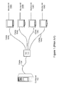
- FIG. 1 illustrates a computer system which supports multiple display devices, i.e., computer monitors, according to the prior art.
- a computer 102 is coupled to a hub 111 , e.g., via a cable 104 .
- the hub 111 is coupled to a plurality of computer displays, i.e., computer monitors 108 A- 108 D via respective cables 104 A- 104 D.
- Multiplexed video signals, and optionally, I/O device signals are sent from the computer 108 to the hub 111 , where the multiplexed video signals are separated and routed over the appropriate cables 104 to respective monitors 108 .
- FIG. 1 shows, in the prior art approach, a computer 102 is coupled to a hub 111 , e.g., via a cable 104 .
- the hub 111 is coupled to a plurality of computer displays, i.e., computer monitors 108 A- 108 D via respective cables 104 A- 104 D.
- the prior art approach necessitates that multiple cables (e.g., 104 A- 104 D) be run from the hub 111 to distribute the video signals.
- the hub 111 receives a single large video frame or image, and partitions the frame into a plurality of sub-frames, each of which constitutes a frame or image for a respective monitor.
- the processing involved in decomposing the single large frame into the respective sub-frames may require complex processing and may greatly limit the flexibility of the system regarding changes in configuration of the system, e.g., addition or subtraction of monitors from the system, changes in resolution of the images, etc.
- the parallel couplings between the hub 111 and the monitors 108 may also require substantially more cable than a single monitor system. As was mentioned above, generally, the cost of running the cable exceeds that of the cable itself, thus, the use of multiple parallel cables to couple the monitors to the hub may involve significant expense, in that in some embodiments, each of the cables 104 A- 104 D may have to be “pulled” through walls, floors, etc., during installation of the system.
- a method and system for transmitting video images from a computer system to multiple monitors over a single cable is disclosed.
- the computer system is located at a first location, and is coupled to a human interface through a cable.
- the human interface may be located at a second location remote from the first location.
- the human interface may include a plurality of frame grabbers and a plurality of monitors.
- the computing system includes a video processor operable to store a plurality of video images.
- the video processor is further configured to transmit a sequence of video frames, each video frame including a video image and a frame identifier.
- the video processor may be configured to transmit the sequence of video frames in a time-division multiplexed fashion.
- the video frames are transmitted across the cable to the plurality of frame grabbers, each of which couples the cable to one of the plurality of monitors.
- Each frame grabber is configured to examine the sequence of video frames.
- Each frame grabber is further configured to select a video frame from the sequence based on the frame identifier, which designates the specific monitor upon which the video frame is to be displayed.
- a frame in the sequence that is not designated for the specific monitor may be allowed to pass through the frame grabber, as well as any subsequent frame grabber, until reaching a frame grabber associated with the monitor designated by its frame identifier.
- the computer is a blade computer.
- the blade computer may execute a software driver that generates video images, places the video images into frames, and inserts a frame identifier into the each video frame.
- the video frames may then be transmitted sequentially onto the serial cable.
- the serial cable may be a CAT 5 cable.
- the frames may be received by frame pods coupled to the serial cable, each of which includes a frame grabber, and is coupled to a monitor. Frames not captured by the frame grabber may be forwarded to subsequent frame pods coupled to the cable.
- the frame pods may be located in their respective monitors.
- the computing system may include a plurality of blade computers, and thus may be configured for allowing a large number of monitors to be coupled to computers by single cables.
- the computing system may be particularly useful where it is necessary to display information on a large number of monitors (e.g. an airport terminal). Transmission of multiplexed video frames to respective frame pods and their associated monitors may reduce cabling requirements for the system by reducing the number of cables which must be “pulled” through walls, ceilings, and so forth.
- FIG. 1 Prior Art
- FIG. 1 illustrates a prior art computer system having a computer and multiple display devices connected to the computer through a hub;
- FIG. 2 illustrates a multi-monitor computer system, according to one embodiment of the present invention
- FIG. 3 illustrates the use of frame-grabbers to distribute image frames to respective monitors over a single cable, according to one embodiment
- FIG. 4 illustrates an embodiment of the multi-monitor computer system in which I/O device signals are included with video signals and transmitted over a single cable;
- FIGS. 5 A- 5 C illustrate video frame management in the multi-monitor system, according to one embodiment
- FIG. 6 illustrates frame timing, according to one embodiment
- FIG. 7 illustrates video frame sequencing, according to one embodiment
- FIG. 8 is a block diagram of a dual monitor drive system based on the Nvidia GEForce video chip, according to one embodiment
- FIG. 9 illustrates a video multiplexing scheme for the dual monitor system of FIG. 8, according to one embodiment
- FIG. 10 illustrates a video encoding scheme for the dual monitor system of FIG. 8, according to one embodiment
- FIG. 11 is a flowchart of a method for generating video signals in a dual monitor system, according to one embodiment
- FIG. 12 illustrates a process for receiving and distributing video frames in a multi-monitor system, according to one embodiment
- FIG. 13 illustrates the relationship between the frame-grabber's input and output, according to one embodiment.
- FIG. 2 Computer System with Multiple Display Devices
- FIG. 2 illustrates a computer system which supports multiple display devices, i.e., computer monitors, according to one embodiment of the present invention.
- the computer at the first location, the monitors and frame pods at the second location, and the human interface may include other devices not shown here.
- the computer 102 may couple to a first frame pod 206 A via the cable 104 .
- the first frame pod 206 A may couple to monitor 108 A.
- the first frame pod 206 A may couple to a second frame pod 206 B, which may couple to monitor 108 B, as well as frame pod 206 C.
- Frame pod 206 C may couple to monitor 108 C and frame pod 206 D.
- frame pod 206 D may couple to monitor 108 D.
- Each frame pod 206 D may comprise a frame grabber as described below.
- the frame pods may be implemented in each of their respective monitors, and hence separate frame pods may are not necessary.
- the system shown includes four monitors, that in various embodiments, the system may also include a greater or lesser number of monitors, and that the methods disclosed herein apply equally.
- other embodiments are possible and contemplated wherein each of the frame grabbers is stored within a single box. In general, a wide variety of configurations for arranging the frame pods/grabbers are possible and contemplated.
- the frame pods 206 /monitors 108 may be linked to the computer 102 in serial fashion via the cable 104 . It should be noted that in another embodiment, the computer 102 may couple to the first frame pod 206 A through a network, such as the Internet.
- the computer 102 stores a video image or frame for each of the monitors 108 A-D.
- the computer 102 generates multiplexed video sequences, wherein the video frames are multiplexed together in a time-division multiplexed fashion.
- the video frames may be multiplexed together using frequency division multiplexing.
- the multiplexed video signals may be transmitted from the computer 102 over the cable 104 to the first frame pod 206 A.
- the first frame pod 206 A may extract video signals targeted to the monitor 108 A, if any, and transmit the extracted signals to the monitor 108 A.
- the multiplexed video signals may then be sent by the first frame pod 206 A to the second frame pod 206 B.
- the second frame pod 206 B may similarly extract video signals targeted to the monitor 108 B, if any, and transmit the extracted signals to the monitor 108 B, sending the multiplexed signals on to the third frame pod 206 C, which, in turn, may extract video signals targeted to the monitor 108 C, if any, and transmit the extracted signals to the monitor 108 C, sending the multiplexed signals on to the fourth frame pod 206 D.
- the fourth frame pod 206 D may extract video signals targeted to the monitor 108 D, if any, and transmit the extracted signals to the monitor 108 D.
- the extraction of video signals for each monitor may be performed by a respective frame grabber in each frame pod 206 , as described below with reference to FIG. 3.
- serial transmission of the multiplexed video signals to the respective frame pods 206 and monitors 108 may substantially reduce cabling requirements for the system, also resulting in a concomitant reduction in the number of cables which must be “pulled” through walls, ceilings, etc. in the installation of the system. Further details of this serial transmission of video signals from the computer to the succession of frame pods 206 and their respective monitors are described below with reference to FIGS. 3 - 13 .
- FIG. 3 Block Diagram of the Multiple Monitor System
- FIG. 3 is a block diagram showing the primary functional elements of the multiple monitor system of FIG. 2, according to one embodiment.
- multiple images 302 A- 302 D may be provided, e.g., by the computer 108 .
- FIG. 3 illustrates a series of (four) video images 302 A- 302 D, also referred to as ‘frames’, sequentially selected and transmitted some distance to a series of frame grabbers (comprised in the frame pods 206 of FIG. 2) over a single cable 104 .
- the images may be sequentially fed to multiple frame grabbers 306 and then fed to the associated monitors 108 .
- the term frame grabber is intended to refer to a unit configured to identify frames targeted for an associated monitor, and to forward these frames to the associated monitor, where they may then be displayed.
- the system may include a single cable distancing system 304 , which may be operable to extend the operational distance for a human interface, i.e., the multiple monitors and/or other human interface devices, located remotely from the computing system 102 .
- a human interface i.e., the multiple monitors and/or other human interface devices
- each of the images in the sequence of images or frames 302 may include a unique identifier indicating a target display, e.g., a target monitor.
- Each frame grabber 306 may examine the frame identifier, and when the appropriate frame grabber 306 detects an appropriate frame 302 , the frame grabber 306 may grab or extract the frame from the serial signal and transmit the grabbed frame or image 302 to the corresponding monitor.
- each frame grabber 306 may be operable to analyze the multiplexed video signal, detect, and extract the appropriate frame 302 from the signal, and send the frame 302 to the associated monitor 108 .
- FIG. 4 Computer Blade Based System with I/O Device Signals
- FIG. 4 illustrates one embodiment of a multi-monitor system where the computer 108 comprises a “computer on a card” or “blade computer” 102 A.
- the blade computer 102 A may serially couple to a series of frame pods 206 , as described above.
- each of the frame pods 206 may couple to a respective computer monitor 108 .
- the blade computer 102 A includes most or all of the functional components of a computer, e.g., processor, memory, power supply, etc., packaged with a blade or drawer form factor, such that multiple computers (blades) 102 A may be co-located, e.g., in a rack or cage, thereby significantly reducing the space requirements for the computers.
- a computer e.g., processor, memory, power supply, etc.
- multiple computers (blades) 102 A may be co-located, e.g., in a rack or cage, thereby significantly reducing the space requirements for the computers.
- a software driver executing in the blade computer 102 A may map images out of memory as sequential frames ( 302 A- 302 D).
- the frame pods 206 i.e., the frame grabbers 306 A- 306 D, may each be operable to select or pick off an assigned frame of video and play it back to the respective monitor 108 at full refresh rate.
- the number of unique monitors supported in the system may be a function of video chip memory and a specified lowest acceptable rewrite rate, discussed in more detail below.
- the number of monitors/frames described herein is exemplary only, and is not intended to limit the number of monitors or frames to any particular value.
- the number of frames and the number of monitors may differ.
- various monitors may display the same information.
- three images may be distributed over nine monitors, where the first two images may each be displayed on four monitors, and the third image may be displayed on the ninth monitor. This type of flexibility is provided by the ability of each frame pod 206 to examine the combined or multiplexed video signal and extract any video frame based on the frame identifier.
- the final frame pod in the series may couple to a USB (universal serial bus) pod 208 .
- the USB pod 208 may couple to one or more I/O devices. also referred to as human interface devices, e.g., keyboard 410 , mouse 411 , included in the computer system's HI.
- the USB pod may thus terminate the line and process signals for all the HI devices.
- the USB pod may also be operable to receive user input from the HI devices and transmit the HI device signals through the cable 104 (and all of the frame pods 206 ) back to the computer 102 A.
- FIGS. 5 A- 5 C Video Frame Management
- FIGS. 5 A- 5 C illustrate video frame management in a computer system, according to one embodiment.
- FIG. 5A shows a sequence of video frames delivered to the monitor at a selected refresh rate.
- the CPU will map instructions to build a video image out of memory and into a video processor, e.g., a graphics card.
- the video processor may take these digital instructions from memory and create, along with proper synchronization information, a video image which may be output as a sequential series of image lines whose aggregation constitutes the video ‘frame’ 1 502 A, i.e., one complete screen or “Window” of video information. This process may continue unabated at a rate typically between 60 and 85 frames per second.
- This signaling is repetitious, in that the same block of video data is output for a single monitor installation.
- This block of video data is typically rewritten by the computer 102 as needed to keep the screen's or window's contents current.
- Several ‘screens’ may reside in the computer's memory and may be written over each other as selected from the active windows screen by either keystrokes or mouse clicks.
- FIG. 5B illustrates a simplified version of the process.
- multiple windows 504 A- 504 C i.e., video images
- These data are typically selected by the video driver to be rendered to through the video card out to the monitor in a standard VESA protocol (component color video plus synchronization data signals). This process is essentially the selection of the start and stop memory locations for the window of choice.
- the video card may select one of the windows, i.e., memory locations, for display, as shown in FIG. 5B.
- the data at the selected memory location, i.e., the selected window 504 A, may then be converted by the video card 506 to an analog video signal 508 , as shown.
- the stream of frames shown in FIG. 5A may be modified such that each frame may be displayed on a different monitor.
- the video driver/processor may be altered such that switching between windows 504 may be performed automatically on a frame basis.
- the video processor 506 may first select and render a first frame, 6 1
- the reader is fully familiar with the VESA defined VGA, SVGA, XVGA, and etc. video signaling protocols employed in contemporary Personal Computer Video Technology. comprising the data of window # 1 504 A.
- the ‘switch’ may be advanced to the memory for Window # 2 and that frame rendered. Finally, the process may select the Window # 3 and render its frame, after which the process returns to Window # 1 .
- This process may be extended to support Window # 1 to Window #‘n’, where the value ‘n’ may be determined and stored in the system during setup or initialization, or may be modified later, and remembered by the computer until changed.
- FIG. 5C illustrates an example video output stream for an “n-window” system.
- the n frames 512 A- 512 Z may be transmitted sequentially as shown, where the sequence cycles back to frame 1 512 A once all of the frames have been transmitted.
- frames 1 512 A through frame n 512 Z may each have an associated frame ID 513 A- 513 Z. These IDs may be used to identify and select each frame from the combined or multiplexed video stream, as mentioned above.
- each frame grabber 306 may have an ID which may be matched to the frame ID to indicate that the frame grabber 306 is to extract the frame for display on the respective monitor 108 . An example of the placement of this frame ID 513 is described below with reference to FIG. 6.
- FIG. 6 Endcoding Format for Frame ID
- FIG. 6 illustrates frame timing, according to one embodiment, and more specifically, FIG. 6 illustrates one embodiment of a format for encoding the frame IDs mentioned above with reference to FIG. 5C.
- a simple frame identifier may be inserted to tag the frame.
- the frame ID may be located in the first line of the ‘blue’ video stream 606 .
- the frame ID may comprise 2 bits, 3 microsecond long, starting 4 microseconds after the end 612 of the first Hsync 604 that occurs during Vsync 602 .
- Frame # 1 may be coded as ‘00’, frame # 2 as ‘01’ frame # 3 as ‘10’, and frame # 4 as ‘11’.
- the rate of refresh of the video driver may be independent of the refresh rate of the individual monitors. That is the video output of the computer can operate at the lowest rate possible in an effort to reduce the bandwidth of the signal being transferred down the cable connecting the computer and the monitors.
- the monitors can operate at their highest refresh rate for the user's satisfaction and viewing ease.
- Clearly a large number of monitors would significantly slow the actual frame data transfer rate and may produce a ‘jumpy’ image on the monitor when used with rapidly changing video data, i.e., ‘action video’. It is anticipated that for normal ‘business’ graphics and video this may not be of consequence.
- FIG. 7 Video Frame Sequencing
- FIG. 7 illustrates video frame sequencing, according to one embodiment. More specifically, FIG. 7 illustrates a video frame sequencing scheme which addresses the “sticky mouse” issue mentioned above.
- the frame 702 containing the mouse/cursor information may be sent on an every-other-frame basis to eliminate the jerkiness of the mouse that would result from a too infrequent refresh.
- Such an output is illustrated in FIG. 7 for a 4 screen (frame) implementation with frame # 2 702 having the mouse in it.
- the frame sequence is frame 1 512 A, frame 2 512 B, frame 3 512 C, frame 2 512 B, frame 4 512 C, frame 2 512 B, frame 1 512 C, and so on, as FIG. 7 indicates, wherein frame 2 512 B is the mouse frame 702 .
- FIG. 8 Block Diagram of a Dual Monitor System Based on Nvidia GEForce Video Chip
- the video Window data stream described above can be produced in at least three ways.
- the first is pure software, that is, the video processor driver software may be altered so that the video processor fully manufactures the data stream.
- a second approach is to perform the process in hardware. For example, several independent video processors may be used to create the images and to multiplex the signals for the images into a single line.
- FIG. 8 is a block diagram of this second approach, as applied to an Nvidia GEForce Video Chip, according to one embodiment. It is noted that the use of the Nvidia GEForce Video Chip is exemplary only, and is not intended to limit the video card or chipset used in the invention to any particular type.
- the third method is a combination of the two, that is most of the frame is created by the software and the video processor, the additional information (including but not limited to the frame ID) may be added by additional hardware.
- the system is a dual monitor drive system based on the Nvidia GEForce video chip.
- This device 804 has two independent outputs, analog and digital, managed by existing Nvidia software.
- the system may multiplex frames from these two outputs down a single cable 104 , e.g., a Category 5 cable, to be captured by a pair of frame stores (grabbers) 306 A and 306 B and distributed to respective monitors 108 A and 108 B, as illustrated.
- the Nvidia based video card 804 has two outputs, output # 1 , which is a digital signal converted to analog via an on-card DAC 816 , and output # 2 , which is analog.
- the output of the card 804 may be multiplexed between the two outputs on a frame-by-frame basis. This output may be based on an alternating presentation of the frames, e.g., a frame from output # 1 , then a frame from output # 2 , then a frame from output # 1 , and on. It is understood that this may cause some discontinuity in the signal output, that is frame # 2 may not be ready for transmittal at the end of frame # 1 .
- FIG. 9 Video Multiplexing Scheme for the Dual Monitor System of FIG. 8
- the NVidia chip has asynchronous outputs, in that the two channels are generated from independent clocks such that when both channels are refreshing at the same rate the actual V and H Sync signals have slightly different periods or frequencies, e.g., 5 to 10 Hz difference, which is the result of independent sources. This feature allows each output to operate at a different refresh rate without complex internal calculations or frequency synthesis.
- FIG. 9 illustrates a video multiplexing scheme for the dual monitor system of FIG. 8, according to one embodiment.
- the basic multiplexing scheme is to send every other frame down the line.
- there may be a gap between the frames of up to just less than two whole frames thus, in a worst case scenario, the system may capture what is effectively every third frame rather than every other frame, as FIG. 9 indicates.
- a best or ideal case is illustrated, where a first video output 902 A and a second video output 904 A are shown with equal period or frequency.
- the two video frame sequences may be multiplexed together seamlessly, with no frame losses or asynchronicities.
- the frequencies of video # 1 902 B and video # 2 904 B may differ such that every third frame of each video stream is selected and multiplexed for transmission to the monitors, as shown by the video streams 902 C and 904 C, resulting in the video stream output 906 . Therefore, at 75 Hz refresh one may expect to see about 27 rewrites per second. This will probably not be noticeable when moving the mouse, although there will likely still be gaps in the video stream. As mentioned above, it is expected that for most applications, e.g., business applications, the slightly slower data presentation rate will be acceptable.
- FIG. 10 Video Encoding Scheme for the Dual Monitor System of FIG. 8
- FIG. 10 illustrates a video encoding scheme for the dual monitor system of FIG. 8, according to one embodiment.
- frames from video input 1 1010 A and video input 2 1010 B may be multiplexed based on information included in the frame.
- Such frame data 1011 may include Vsync 1 1001 A, Hsync 1 1002 A, Vsync 2 1101 B, and Hsync 1 1002 B, as well as Blue 1 1003 A, Blue 2 1003 B, an identified output 1004 , and a switch signal slot 1005 .
- the particular data stored in each frame may occupy respective time slots in the transmitted frame signal.
- Vsync 1 1001 A, Hsync 1 1002 A, Vsync 2 1001 B, and Hsync 1 1002 B are the operative stimulants for the system, controlling the sequencing of the two input video frame streams 1010 A and 1010 B.
- the lines to the blue signals, Blue 1 1003 A and Blue 2 1003 B may transition from a tri-stage or high impedance state to that of high (1 Volt) to indicate the presence of data.
- the time slot marked ‘ID’d Output' 1004 may differentiate the two videos for a given board.
- the time slot marked ‘SW’ may be used when 4 such frame grabbers are used and 4 video signals are present on the line, as indicated by the 2/4 mode switch 1006 .
- One example of process flow for the multiplexing process is described below with reference to FIG. 11.
- FIG. 11 Flowchart for Generating Video Signals in a Dual Monitoring System
- FIG. 11 is a flowchart of a method for generating video signals in the dual monitor system described above with reference to FIGS. 8 - 10 , according to one embodiment.
- FIG. 11 shows, the same basic steps are performed for a frame from each video stream.
- a frame from video stream 1 1010 A is processed first, then the equivalent steps performed for a frame from video stream 2 1010 B.
- the presence of the VSync 1 1001 A is tested. In other words, the method determines if the vertical sync signal for the first video stream 1010 A is present. If the VSync 1 1001 A is not present, the method step repeats, as shown, until the VSync 1 signal is detected.
- the signal of the first video stream 1010 A may be output, as indicated. Then, as 1103 shows, the method may repeatedly check for the end of the Hsync 1 signal 1002 A, i.e., the end of the horizontal sync signal for the first video stream 1010 A. When the end of the Hsync 1 1002 A is detected, then in 1104 a delay time 1 may be inserted into the stream, and in 1105 , the blue 1 signal line set to low, as shown.
- a delay time 2 may be inserted into the stream, and the blue 1 signal line set to SW, as shown in 1107 .
- a delay time 3 may then be inserted into the stream, as indicated in 1108 , and the blue 1 signal line set to low again, 1109 shows.
- the method may then check for the presence of the VSync 1 signal, as 1110 shows. Once the VSync 1 signal is detected, the video 1 frame is complete.
- the signal of the second video stream 1010 B may be output, as indicated. Then, the method may repeatedly check for the end of the Hsync 2 signal 1002 B, i.e., the end of the horizontal sync signal for the second video stream 1010 B, as 1113 shows,. When the end of the Hsync 2 1002 B is detected, then in 1114 a delay time 1 may be inserted into the stream, and in 1115 , the blue 2 signal line set to low, as shown.
- a delay time 2 may be inserted into the stream, and the blue 2 signal line set to SW, as shown in 1117 .
- a delay time 3 may then be inserted into the stream, as indicated in 1118 , and the blue 2 signal line set to low again, 1119 shows.
- the method may then check for the presence of the VSync 2 signal 1001 B, as 1120 shows. Once the VSync 2 signal is detected, the video 2 frame is complete.
- the method may receive two video frame streams and multiplex the streams together on a frame by frame basis, based on information included in the frame data.
- each frame grabber may implement a method of saving a frame or window and then replaying it to the respective monitor.
- FIG. 12 A more detailed block diagram of a frame grabber 306 is shown in FIG. 12, described below.
- FIG. 12 Frame Grabber
- FIG. 12 illustrates a process for receiving and distributing video frames in a multi-monitor system, according to one embodiment.
- the video signal is fed to all the frame grabbers 306 , which then perform the extraction of the appropriate frame for sending to a respective monitor.
- a video signal 1210 may be received by an equalizer and line interface 1202 .
- the video signal may be interfaced and equalized to compensate for cable issues of time and frequency.
- the video signal 1210 may then be split and sent to a Phase Locked Loop (PLL) element 1204 and an analog/digital converter 1206 , as shown.
- PLL Phase Locked Loop
- the basic pixel clock rate may be extracted by the PLL to operate as the local clock.
- the image may be converted from analog to digital by the analog/digital converter 1206 , and fed to the memory 1212 .
- the control module may access the frame data, examining the first line of each frame for its ID code. In one embodiment, all first lines may be the same, and so may simply be written over in the memory. If the frame ID is the same as the frame grabber ID then the rest of the video image may be saved.
- the video image or frame may be sent to a digital/analog converter 1208 which converts the digital frame to an analog signal.
- the control module 1220 may then send the resulting signal to the associated monitor 108 .
- FIG. 13 Frame Grabber Input and Output
- FIG. 13 illustrates the relationship between the first frame-grabber's input 1302 and output 1304 , according to one embodiment.
- a sequential video stream 1302 may be received from the computer 102 .
- the video sequence comprises frame 1 A 1312 A, frame 2 A 1314 A, frame 3 A 1316 A, and frame 4 A 1318 A, followed by frame 1 B 1312 B, frame 2 B 1314 B, frame 3 B 1316 B, and so on.
- video frames from 4 inputs are multiplexed together.
- frames for a given cycle e.g., ‘A’
- frames for the next cycle e.g., ‘B’
- the frame grabber 306 A identifies and ‘grabs’ frame 1 A 1312 A, based on the frame's ID (by matching it with the frame grabber's ID).
- the frame grabber 306 A may then send the grabbed frame 1 A 1312 A repeatedly to the monitor 108 A, as shown in the first four frames of the output stream 1304 .
- the frame grabber 306 A detects the next frame from the first video source, i.e., frame 1 B 1312 B, the frame is extracted and sent to the monitor 108 A, as shown.
- the output frames may be sent to the monitor 108 A at the monitor's refresh rate.
- the rates of the input and the output may differ, e.g., the frame grabber 306 A may receive frames at a first rate, e.g., 60 Hz, while sending the output frames to the monitor 108 A at a different rate, e.g., 75 Hz.
- a first rate e.g. 60 Hz
- a different rate e.g. 75 Hz.
- various embodiments of the systems and methods described herein may provide means for driving multiple monitors with a single computer, where multiplexed video frames may be transmitted over a single serial cable, and extracted sequentially by frame grabbers associated with respective monitors.
- the video data stream is a sequence of complete image frames or windows
- a unique frame identification is attached to each frame
- the frame grabber is an independent and complete frame reception node
- the system is scaleable from 2 to N nodes;
Abstract
Description
- This application claims priority to U.S. provisional application serial No. 60/370,889 entitled “CONNECTING MULTIPLE MONITORS TO A COMPUTER USING A SINGLE CABLE” filed Apr. 8, 2002.
- 1. Field of the Invention
- The present invention relates generally to computer systems and specifically to operation of multiple monitors with a single computer over a single cable. The invention further relates to extension of the operational distance between the computer and the monitors.
- 2. Description of the Related Art
- The components of a computer system (such as PCs, minicomputers and mainframes) may be divided into two functional units—a computing system and a human interface (or “HI”) to the computing system. For a PC, the computing system may be the CPU, memory, hard drive, power supply and similar components. The computing system may be comprised in a chassis which holds the motherboard, power supply, hard drive and the like. The computer system may also be implemented in other forms, such as a blade computer as described in U.S. Pat. No. 6,012,101 entitled “Computer Network Having Commonly Located Computer Systems”, or U.S. patent application Ser. No. 09/728,667 entitled “Computer On A Card With A remote Human Interface” filed Dec. 1, 2000. The human interface, on the other hand, may comprise those devices that humans use to transfer information to and/or receive information from the computing system. The most commonly recognized devices which form part of the human interface with the computing system include the monitor, keyboard, mouse and printer. The human interface may also include a variety of other devices, such as a joystick, trackball, touchpad, microphone, speakers, and telephone, as well as other devices too numerous to specifically mention.
- Increasingly, HIs for computer systems include multiple monitors for presenting large amounts of information to a user. For example, financial or stock analysis workstations typically include at least two monitors to display various tables, graphs, documents, and program interfaces to the analyst. Generally, this is accomplished through the use of multiple (usually two) video cards in the computer, although there are some video cards which support two independent video outputs. Drawbacks to this approach include the cost of providing multiple video cards (or special video cards with multiple outputs) for the computer system, as well as the limitation on the number of monitors supported (usually two or three), due to the limited number of slots and/or buses available on the computer.
- In most multi-display computer systems, e.g., current PC architectures, the human interface (e.g., the display monitor, mouse, and keyboard, etc.) is closely located to the computer system, by a distance typically less than about 10 to 15 feet. This distance constraint severely limits the placement of the multiple video monitors in a system, and thus, limits the usability and flexibility of the system. In some current multi-display computer systems, the operational distance from the computer to the video displays has been extended, e.g., by converting digital video signals to analog signals for propagation over distances up to ˜100 feet, and by using compensation amplifiers in the case of longer cable runs.
- However, current approaches to extended multiple monitor computer systems require individual cables for each monitor. In other words, current approaches include a hub which connects to the computer, and which has multiple outputs for connecting with respective multiple monitors via respective multiple cables. Thus, if the computer system includes four monitors at the HI location, then four separate cables must be run from the hub to the displays, increasing the expense of the system.
- Additionally, in the installation of cabling, the cost of pulling the cable, e.g., through walls, ceilings, etc., may greatly exceed the cost of the cable, and so the use of multiple cables to connect the monitors may involve substantial expense. These problems may be illustrated more clearly by FIG. 1 and it's associated text.
- FIG. 1—Computer System with Multiple Display Devices (Prior Art)
- FIG. 1 illustrates a computer system which supports multiple display devices, i.e., computer monitors, according to the prior art. As FIG. 1 shows, in the prior art approach, a
computer 102 is coupled to ahub 111, e.g., via acable 104. Thehub 111, in turn, is coupled to a plurality of computer displays, i.e.,computer monitors 108A-108D viarespective cables 104A-104D. Multiplexed video signals, and optionally, I/O device signals, are sent from the computer 108 to thehub 111, where the multiplexed video signals are separated and routed over theappropriate cables 104 to respective monitors 108. Thus, as FIG. 1 shows, the prior art approach necessitates that multiple cables (e.g., 104A-104D) be run from thehub 111 to distribute the video signals. In this prior art approach, thehub 111 receives a single large video frame or image, and partitions the frame into a plurality of sub-frames, each of which constitutes a frame or image for a respective monitor. The processing involved in decomposing the single large frame into the respective sub-frames may require complex processing and may greatly limit the flexibility of the system regarding changes in configuration of the system, e.g., addition or subtraction of monitors from the system, changes in resolution of the images, etc. - The parallel couplings between the
hub 111 and the monitors 108 may also require substantially more cable than a single monitor system. As was mentioned above, generally, the cost of running the cable exceeds that of the cable itself, thus, the use of multiple parallel cables to couple the monitors to the hub may involve significant expense, in that in some embodiments, each of thecables 104A-104D may have to be “pulled” through walls, floors, etc., during installation of the system. - A method and system for transmitting video images from a computer system to multiple monitors over a single cable is disclosed. In one embodiment, the computer system is located at a first location, and is coupled to a human interface through a cable. The human interface may be located at a second location remote from the first location. The human interface may include a plurality of frame grabbers and a plurality of monitors.
- In one embodiment, the computing system includes a video processor operable to store a plurality of video images. The video processor is further configured to transmit a sequence of video frames, each video frame including a video image and a frame identifier. The video processor may be configured to transmit the sequence of video frames in a time-division multiplexed fashion. The video frames are transmitted across the cable to the plurality of frame grabbers, each of which couples the cable to one of the plurality of monitors. Each frame grabber is configured to examine the sequence of video frames. Each frame grabber is further configured to select a video frame from the sequence based on the frame identifier, which designates the specific monitor upon which the video frame is to be displayed. A frame in the sequence that is not designated for the specific monitor may be allowed to pass through the frame grabber, as well as any subsequent frame grabber, until reaching a frame grabber associated with the monitor designated by its frame identifier.
- In one embodiment, the computer is a blade computer. The blade computer may execute a software driver that generates video images, places the video images into frames, and inserts a frame identifier into the each video frame. The video frames may then be transmitted sequentially onto the serial cable. In one embodiment, the serial cable may be a CAT 5 cable. The frames may be received by frame pods coupled to the serial cable, each of which includes a frame grabber, and is coupled to a monitor. Frames not captured by the frame grabber may be forwarded to subsequent frame pods coupled to the cable. In one embodiment, the frame pods may be located in their respective monitors.
- The computing system may include a plurality of blade computers, and thus may be configured for allowing a large number of monitors to be coupled to computers by single cables. The computing system may be particularly useful where it is necessary to display information on a large number of monitors (e.g. an airport terminal). Transmission of multiplexed video frames to respective frame pods and their associated monitors may reduce cabling requirements for the system by reducing the number of cables which must be “pulled” through walls, ceilings, and so forth.
- Other aspects of the invention will become apparent upon reading the following detailed description and upon reference to the accompanying drawings in which:
- FIG. 1 (Prior Art) illustrates a prior art computer system having a computer and multiple display devices connected to the computer through a hub;
- FIG. 2 illustrates a multi-monitor computer system, according to one embodiment of the present invention;
- FIG. 3 illustrates the use of frame-grabbers to distribute image frames to respective monitors over a single cable, according to one embodiment;
- FIG. 4 illustrates an embodiment of the multi-monitor computer system in which I/O device signals are included with video signals and transmitted over a single cable;
- FIGS. 5A-5C illustrate video frame management in the multi-monitor system, according to one embodiment;
- FIG. 6 illustrates frame timing, according to one embodiment;
- FIG. 7 illustrates video frame sequencing, according to one embodiment;
- FIG. 8 is a block diagram of a dual monitor drive system based on the Nvidia GEForce video chip, according to one embodiment;
- FIG. 9 illustrates a video multiplexing scheme for the dual monitor system of FIG. 8, according to one embodiment;
- FIG. 10 illustrates a video encoding scheme for the dual monitor system of FIG. 8, according to one embodiment;
- FIG. 11 is a flowchart of a method for generating video signals in a dual monitor system, according to one embodiment;
- FIG. 12 illustrates a process for receiving and distributing video frames in a multi-monitor system, according to one embodiment; and
- FIG. 13 illustrates the relationship between the frame-grabber's input and output, according to one embodiment.
- While the invention is susceptible to various modifications and alternative forms, specific embodiments thereof are shown by way of example in the drawings and are herein described in detail. It should be understood, however, that the drawings and detailed description thereto are not intended to limit the invention to the particular form disclosed, but on the contrary, the intention is to cover all modifications, equivalents and alternatives falling within the spirit and scope of the present invention as defined by the appended claims.
- Incorporation by Reference
- The following patents and patent applications are hereby incorporated by reference as though fully and completely set forth herein:
- U.S. Pat. No. 6,012,101 titled “Computer Network Having Commonly Located Computer Systems” issued on Jan. 4, 2000, whose inventors are Andrew Heller, Barry Thornton, Daniel Barrett, and Charles Ely;
- U.S. Pat. No. 6,119,146 titled “Computer Network Having Multiple Remotely Located Human Interfaces Sharing a Common Computing System” issued on Sep. 12, 2000, whose inventors are Andrew Heller, Barry Thornton, Daniel Barrett, and Charles Ely;
- U.S. Pat. No. 6,038,616 titled “Computer System With Remotely Located Interface Where Signals are Encoded at the Computer System, Transferred Through a 4-wire Cable, and Decoded at the Interface” issued on Mar. 14, 2000, whose inventors are Andrew Heller, Barry Thornton, Daniel Barrett, and Charles Ely;
- U.S. Pat. No. 6,070,214 titled “Serially Linked Bus Bridge For Expanding Access Over A First Bus To A Second Bus” issued on May 30, 2000, whose inventor is Frank Ahern;
- U.S. Pat. No. 5,764,924 titled “Method And Apparatus For Extending A Local PCI Bus To A Remote I/O Backplane” issued on Jun. 9, 1998, whose inventor is Soon Chul Hong;
- U.S. Pat. No. 6,003,105 titled “Long-Haul PCI-to-PCI Bridge” issued on Dec. 14, 1999, whose inventors are Dominique Vicard, Jean-Paul Moiroux, and Pierre-Yves Thoulon;
- U.S. patent application Ser. No. 09/728,667 titled “Computer On A Card With A Remote Human Interface” filed on Dec. 1, 2000, whose inventors are Andrew Heller and Barry Thornton; and
- U.S. patent application Ser. No. 09/728,669 titled “A System Of Co-Located Computers In a Framework Including Removable Function Modules for Adding Modular Functionality” filed on Dec. 1, 2000, whose inventor is Barry Thornton.
- U.S. patent application Ser. No. 09/619,989 titled “System and Method for Providing a Remote Universal Serial Bus” filed on Jul. 20, 2000, whose inventor is Barry Thornton.
- U.S. patent application Ser. No. 09/680,760 titled “System and Method for Combining Computer Video and Remote Universal Serial Bus In An Extended Cable” filed on Oct. 6, 2000, whose inventor is Barry Thornton.
- FIG. 2—Computer System with Multiple Display Devices
- FIG. 2 illustrates a computer system which supports multiple display devices, i.e., computer monitors, according to one embodiment of the present invention. The computer at the first location, the monitors and frame pods at the second location, and the human interface may include other devices not shown here. As FIG. 2 shows, in this approach, the
computer 102 may couple to afirst frame pod 206A via thecable 104. As FIG. 2 also shows, thefirst frame pod 206A may couple to monitor 108A. Additionally, thefirst frame pod 206A may couple to asecond frame pod 206B, which may couple to monitor 108B, as well asframe pod 206C.Frame pod 206C may couple to monitor 108C andframe pod 206D. Finally,frame pod 206D may couple to monitor 108D. Eachframe pod 206D may comprise a frame grabber as described below. In another embodiment, the frame pods may be implemented in each of their respective monitors, and hence separate frame pods may are not necessary. It should be noted that, although the system shown includes four monitors, that in various embodiments, the system may also include a greater or lesser number of monitors, and that the methods disclosed herein apply equally. Furthermore, other embodiments are possible and contemplated wherein each of the frame grabbers is stored within a single box. In general, a wide variety of configurations for arranging the frame pods/grabbers are possible and contemplated. - Thus, the frame pods 206/monitors 108 may be linked to the
computer 102 in serial fashion via thecable 104. It should be noted that in another embodiment, thecomputer 102 may couple to thefirst frame pod 206A through a network, such as the Internet. - In one embodiment, the
computer 102 stores a video image or frame for each of themonitors 108A-D. Thecomputer 102 generates multiplexed video sequences, wherein the video frames are multiplexed together in a time-division multiplexed fashion. In another embodiment, the video frames may be multiplexed together using frequency division multiplexing. The multiplexed video signals may be transmitted from thecomputer 102 over thecable 104 to thefirst frame pod 206A. Thefirst frame pod 206A may extract video signals targeted to themonitor 108A, if any, and transmit the extracted signals to themonitor 108A. The multiplexed video signals may then be sent by thefirst frame pod 206A to thesecond frame pod 206B. Thesecond frame pod 206B may similarly extract video signals targeted to themonitor 108B, if any, and transmit the extracted signals to themonitor 108B, sending the multiplexed signals on to thethird frame pod 206C, which, in turn, may extract video signals targeted to themonitor 108C, if any, and transmit the extracted signals to themonitor 108C, sending the multiplexed signals on to thefourth frame pod 206D. Thefourth frame pod 206D may extract video signals targeted to themonitor 108D, if any, and transmit the extracted signals to themonitor 108D. The extraction of video signals for each monitor may be performed by a respective frame grabber in each frame pod 206, as described below with reference to FIG. 3. - It is further noted that the serial transmission of the multiplexed video signals to the respective frame pods 206 and monitors 108 may substantially reduce cabling requirements for the system, also resulting in a concomitant reduction in the number of cables which must be “pulled” through walls, ceilings, etc. in the installation of the system. Further details of this serial transmission of video signals from the computer to the succession of frame pods 206 and their respective monitors are described below with reference to FIGS. 3-13.
- FIG. 3—Block Diagram of the Multiple Monitor System
- FIG. 3 is a block diagram showing the primary functional elements of the multiple monitor system of FIG. 2, according to one embodiment. As FIG. 3 shows,
multiple images 302A-302D may be provided, e.g., by the computer 108. More specifically, FIG. 3 illustrates a series of (four)video images 302A-302D, also referred to as ‘frames’, sequentially selected and transmitted some distance to a series of frame grabbers (comprised in the frame pods 206 of FIG. 2) over asingle cable 104. In other words, the images may be sequentially fed to multiple frame grabbers 306 and then fed to the associated monitors 108. As used herein, the term frame grabber is intended to refer to a unit configured to identify frames targeted for an associated monitor, and to forward these frames to the associated monitor, where they may then be displayed. - As FIG. 3 also shows, the system may include a single
cable distancing system 304, which may be operable to extend the operational distance for a human interface, i.e., the multiple monitors and/or other human interface devices, located remotely from thecomputing system 102. For more information regarding the extension of operation distance from the computer to a remote human interface, please see U.S. Pat. No. 6,038,616 titled “Computer System With Remotely Located Interface Where Signals are Encoded at the Computer System, Transferred Through a 4-wire Cable, and Decoded at the Interface” issued on Mar. 14, 2000, U.S. Pat. No. 6,070,214 titled “Serially Linked Bus Bridge For Expanding Access Over A First Bus To A Second Bus” issued on May 30, 2000, U.S. patent application Ser. No. 09/619,989 titled “System and Method for Providing a Remote Universal Serial Bus” filed on Jul. 20, 2000, and U.S. patent application Ser. No. 09/680,760 titled “System and Method for Combining Computer Video and Remote Universal Serial Bus In An Extended Cable” filed on Oct. 6, 2000, all of which were incorporated by reference above. - In one embodiment, each of the images in the sequence of images or frames 302 may include a unique identifier indicating a target display, e.g., a target monitor. Each frame grabber 306 may examine the frame identifier, and when the appropriate frame grabber 306 detects an appropriate frame 302, the frame grabber 306 may grab or extract the frame from the serial signal and transmit the grabbed frame or image 302 to the corresponding monitor. Thus, each frame grabber 306 may be operable to analyze the multiplexed video signal, detect, and extract the appropriate frame 302 from the signal, and send the frame 302 to the associated monitor 108.
- FIG. 4—Computer Blade Based System with I/O Device Signals
- FIG. 4 illustrates one embodiment of a multi-monitor system where the computer 108 comprises a “computer on a card” or “blade computer” 102A. As shown in FIG. 4, the
blade computer 102A may serially couple to a series of frame pods 206, as described above. As also described above, each of the frame pods 206 may couple to a respective computer monitor 108. As is commonly known in the art, theblade computer 102A includes most or all of the functional components of a computer, e.g., processor, memory, power supply, etc., packaged with a blade or drawer form factor, such that multiple computers (blades) 102A may be co-located, e.g., in a rack or cage, thereby significantly reducing the space requirements for the computers. For more information on blade computers and co-located computer systems, please see U.S. patent application Ser. No. 09/728,667 titled “Computer On A Card With A Remote Human Interface” filed on Dec. 1, 2000, and U.S. patent application Ser. No. 09/728,669 titled “A System Of Co-Located Computers In a Framework Including Removable Function Modules for Adding Modular Functionality” filed on Dec. 1, 2000, which were incorporated by reference above. It should be noted that the use of a blade computer as thecomputer 102 is meant as an example only, and is not intended to limit the type ofcomputer 102 used in the system to any particular type or form. - In this embodiment, a software driver executing in the
blade computer 102A may map images out of memory as sequential frames (302A-302D). The frame pods 206, i.e., theframe grabbers 306A-306D, may each be operable to select or pick off an assigned frame of video and play it back to the respective monitor 108 at full refresh rate. It is noted that in one embodiment, the number of unique monitors supported in the system may be a function of video chip memory and a specified lowest acceptable rewrite rate, discussed in more detail below. Again, it is noted that the number of monitors/frames described herein is exemplary only, and is not intended to limit the number of monitors or frames to any particular value. Additionally, it is noted that in some embodiments of the system, the number of frames and the number of monitors may differ. For example, in an airport terminal application of the system, various monitors may display the same information. Thus, in a simple example, three images may be distributed over nine monitors, where the first two images may each be displayed on four monitors, and the third image may be displayed on the ninth monitor. This type of flexibility is provided by the ability of each frame pod 206 to examine the combined or multiplexed video signal and extract any video frame based on the frame identifier. - As FIG. 4 also shows, the final frame pod in the series, in this example,
frame pod 206B, may couple to a USB (universal serial bus) pod 208. The USB pod 208 may couple to one or more I/O devices. also referred to as human interface devices, e.g.,keyboard 410,mouse 411, included in the computer system's HI. The USB pod may thus terminate the line and process signals for all the HI devices. The USB pod may also be operable to receive user input from the HI devices and transmit the HI device signals through the cable 104 (and all of the frame pods 206) back to thecomputer 102A. - FIGS. 5A-5C—Video Frame Management
- FIGS. 5A-5C illustrate video frame management in a computer system, according to one embodiment. FIG. 5A shows a sequence of video frames delivered to the monitor at a selected refresh rate. In a typical computer video display system the CPU will map instructions to build a video image out of memory and into a video processor, e.g., a graphics card. The video processor may take these digital instructions from memory and create, along with proper synchronization information, a video image which may be output as a sequential series of image lines whose aggregation constitutes the video ‘frame’1 502A, i.e., one complete screen or “Window” of video information. This process may continue unabated at a rate typically between 60 and 85 frames per second. This signaling is repetitious, in that the same block of video data is output for a single monitor installation. This block of video data is typically rewritten by the
computer 102 as needed to keep the screen's or window's contents current. Several ‘screens’ may reside in the computer's memory and may be written over each other as selected from the active windows screen by either keystrokes or mouse clicks. - In a typical computer application the multiple window capabilities, e.g., of Microsoft Windows 2000 or XP are supported by a section of memory assigned to hold the data constituting the windows. FIG. 5B illustrates a simplified version of the process. As FIG. 5B shows,
multiple windows 504A-504C, i.e., video images, may be stored incomputer memory 510, each with a start and stop location in the memory address space. These data are typically selected by the video driver to be rendered to through the video card out to the monitor in a standard VESA protocol (component color video plus synchronization data signals). This process is essentially the selection of the start and stop memory locations for the window of choice. Thus, in response to user input, such as a mouse click activating or selecting a window as the active window, the video card may select one of the windows, i.e., memory locations, for display, as shown in FIG. 5B. The data at the selected memory location, i.e., the selectedwindow 504A, may then be converted by the video card 506 to ananalog video signal 508, as shown. - In one embodiment of the present invention, the stream of frames shown in FIG. 5A may be modified such that each frame may be displayed on a different monitor. In other words, the video driver/processor may be altered such that switching between windows 504 may be performed automatically on a frame basis. In other words, for a three-monitor example, the video processor 506 may first select and render a first frame, 6 1 For the sake of this RFQ it is assumed that the reader is fully familiar with the VESA defined VGA, SVGA, XVGA, and etc. video signaling protocols employed in contemporary Personal Computer Video Technology. comprising the data of
window # 1 504A. With the completion of the rendering of a frame ofWindow # 1, the ‘switch’ may be advanced to the memory forWindow # 2 and that frame rendered. Finally, the process may select theWindow # 3 and render its frame, after which the process returns toWindow # 1. This process may be extended to supportWindow # 1 to Window #‘n’, where the value ‘n’ may be determined and stored in the system during setup or initialization, or may be modified later, and remembered by the computer until changed. - FIG. 5C illustrates an example video output stream for an “n-window” system. The n frames 512A-512Z may be transmitted sequentially as shown, where the sequence cycles back to
frame 1 512A once all of the frames have been transmitted. As FIG. 5C shows, frames 1 512A throughframe n 512Z may each have an associatedframe ID 513A-513Z. These IDs may be used to identify and select each frame from the combined or multiplexed video stream, as mentioned above. In one embodiment, each frame grabber 306 may have an ID which may be matched to the frame ID to indicate that the frame grabber 306 is to extract the frame for display on the respective monitor 108. An example of the placement of this frame ID 513 is described below with reference to FIG. 6. - FIG. 6—Encoding Format for Frame ID
- FIG. 6 illustrates frame timing, according to one embodiment, and more specifically, FIG. 6 illustrates one embodiment of a format for encoding the frame IDs mentioned above with reference to FIG. 5C. As FIG. 6 shows, for each rendered frame, a simple frame identifier may be inserted to tag the frame. In this example embodiment, the frame ID may be located in the first line of the ‘blue’
video stream 606. In an embodiment where four different frames and/or displays are supported, the frame ID may comprise 2 bits, 3 microsecond long, starting 4 microseconds after theend 612 of thefirst Hsync 604 that occurs duringVsync 602.Frame # 1 may be coded as ‘00’,frame # 2 as ‘01’frame # 3 as ‘10’, andframe # 4 as ‘11’. - It is clear that in such a system the rate of refresh of the video driver may be independent of the refresh rate of the individual monitors. That is the video output of the computer can operate at the lowest rate possible in an effort to reduce the bandwidth of the signal being transferred down the cable connecting the computer and the monitors. The monitors can operate at their highest refresh rate for the user's satisfaction and viewing ease. Clearly a large number of monitors would significantly slow the actual frame data transfer rate and may produce a ‘jumpy’ image on the monitor when used with rapidly changing video data, i.e., ‘action video’. It is anticipated that for normal ‘business’ graphics and video this may not be of consequence. A further possible consequence of the distribution of the frame rate across multiple monitors is “mouse jump”, in which the cursor or mouse may appear to be ‘sticky’, remaining in one location for a period, then suddenly jumping to another location, skipping the mouse positions in between. This issue is addressed below with reference to FIG. 7.
- FIG. 7—Video Frame Sequencing
- FIG. 7 illustrates video frame sequencing, according to one embodiment. More specifically, FIG. 7 illustrates a video frame sequencing scheme which addresses the “sticky mouse” issue mentioned above. In this embodiment, the
frame 702 containing the mouse/cursor information may be sent on an every-other-frame basis to eliminate the jerkiness of the mouse that would result from a too infrequent refresh. Such an output is illustrated in FIG. 7 for a 4 screen (frame) implementation withframe # 2 702 having the mouse in it. Thus, the frame sequence isframe 1 512A,frame 2 512B,frame 3 512C,frame 2 512B,frame 4 512C,frame 2 512B,frame 1 512C, and so on, as FIG. 7 indicates, whereinframe 2 512B is themouse frame 702. - FIG. 8—Block Diagram of a Dual Monitor System Based on Nvidia GEForce Video Chip
- The video Window data stream described above can be produced in at least three ways. The first is pure software, that is, the video processor driver software may be altered so that the video processor fully manufactures the data stream. A second approach is to perform the process in hardware. For example, several independent video processors may be used to create the images and to multiplex the signals for the images into a single line. FIG. 8 is a block diagram of this second approach, as applied to an Nvidia GEForce Video Chip, according to one embodiment. It is noted that the use of the Nvidia GEForce Video Chip is exemplary only, and is not intended to limit the video card or chipset used in the invention to any particular type. The third method is a combination of the two, that is most of the frame is created by the software and the video processor, the additional information (including but not limited to the frame ID) may be added by additional hardware.
- As FIG. 8 shows, in this example, the system is a dual monitor drive system based on the Nvidia GEForce video chip. This
device 804 has two independent outputs, analog and digital, managed by existing Nvidia software. The system may multiplex frames from these two outputs down asingle cable 104, e.g., a Category 5 cable, to be captured by a pair of frame stores (grabbers) 306A and 306B and distributed torespective monitors - More specifically, the Nvidia based
video card 804 has two outputs,output # 1, which is a digital signal converted to analog via an on-card DAC 816, andoutput # 2, which is analog. Based on the VSync, the output of thecard 804 may be multiplexed between the two outputs on a frame-by-frame basis. This output may be based on an alternating presentation of the frames, e.g., a frame fromoutput # 1, then a frame fromoutput # 2, then a frame fromoutput # 1, and on. It is understood that this may cause some discontinuity in the signal output, that isframe # 2 may not be ready for transmittal at the end offrame # 1. - FIG. 9—Video Multiplexing Scheme for the Dual Monitor System of FIG. 8
- In the embodiment of FIG. 8, the NVidia chip has asynchronous outputs, in that the two channels are generated from independent clocks such that when both channels are refreshing at the same rate the actual V and H Sync signals have slightly different periods or frequencies, e.g., 5 to 10 Hz difference, which is the result of independent sources. This feature allows each output to operate at a different refresh rate without complex internal calculations or frequency synthesis.
- FIG. 9 illustrates a video multiplexing scheme for the dual monitor system of FIG. 8, according to one embodiment. The basic multiplexing scheme is to send every other frame down the line. In practice, there may be a gap between the frames of up to just less than two whole frames, thus, in a worst case scenario, the system may capture what is effectively every third frame rather than every other frame, as FIG. 9 indicates.
- At the top of FIG. 9, a best or ideal case is illustrated, where a
first video output 902A and asecond video output 904A are shown with equal period or frequency. Thus, in the ideal case, the two video frame sequences may be multiplexed together seamlessly, with no frame losses or asynchronicities. In contrast, in the expected case, the frequencies ofvideo # 1 902B andvideo # 2 904B may differ such that every third frame of each video stream is selected and multiplexed for transmission to the monitors, as shown by the video streams 902C and 904C, resulting in thevideo stream output 906. Therefore, at 75 Hz refresh one may expect to see about 27 rewrites per second. This will probably not be noticeable when moving the mouse, although there will likely still be gaps in the video stream. As mentioned above, it is expected that for most applications, e.g., business applications, the slightly slower data presentation rate will be acceptable. - FIG. 10—Video Encoding Scheme for the Dual Monitor System of FIG. 8
- FIG. 10 illustrates a video encoding scheme for the dual monitor system of FIG. 8, according to one embodiment. As FIG. 10 shows, frames from
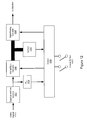
video input 1 1010A andvideo input 2 1010B may be multiplexed based on information included in the frame.Such frame data 1011 may includeVsync1 1001A,Hsync1 1002A, Vsync2 1101B, andHsync1 1002B, as well asBlue1 1003A,Blue2 1003B, an identifiedoutput 1004, and aswitch signal slot 1005. The particular data stored in each frame may occupy respective time slots in the transmitted frame signal. - In this process the vertical and horizontal synchronization signals for the two video streams,
Vsync1 1001A,Hsync1 1002A,Vsync2 1001B, andHsync1 1002B, are the operative stimulants for the system, controlling the sequencing of the two input video frame streams 1010A and 1010B. The lines to the blue signals,Blue1 1003A andBlue2 1003B may transition from a tri-stage or high impedance state to that of high (1 Volt) to indicate the presence of data. The time slot marked ‘ID’d Output' 1004 may differentiate the two videos for a given board. The time slot marked ‘SW’ may be used when 4 such frame grabbers are used and 4 video signals are present on the line, as indicated by the 2/4mode switch 1006. One example of process flow for the multiplexing process is described below with reference to FIG. 11. - FIG. 11—Flowchart for Generating Video Signals in a Dual Monitoring System
- FIG. 11 is a flowchart of a method for generating video signals in the dual monitor system described above with reference to FIGS. 8-10, according to one embodiment. As FIG. 11 shows, the same basic steps are performed for a frame from each video stream. In this example, a frame from
video stream 1 1010A is processed first, then the equivalent steps performed for a frame fromvideo stream 2 1010B. - In 1101, the presence of the
VSync1 1001A is tested. In other words, the method determines if the vertical sync signal for thefirst video stream 1010A is present. If theVSync1 1001A is not present, the method step repeats, as shown, until the VSync1 signal is detected. - Once the
VSync 1 1001A is detected, then in 1102, the signal of thefirst video stream 1010A may be output, as indicated. Then, as 1103 shows, the method may repeatedly check for the end of theHsync1 signal 1002A, i.e., the end of the horizontal sync signal for thefirst video stream 1010A. When the end of theHsync1 1002A is detected, then in 1104 a delay time1 may be inserted into the stream, and in 1105, the blue1 signal line set to low, as shown. - Then, in 1106, a delay time2 may be inserted into the stream, and the blue1 signal line set to SW, as shown in 1107. A delay time3 may then be inserted into the stream, as indicated in 1108, and the blue1 signal line set to low again, 1109 shows. The method may then check for the presence of the VSync1 signal, as 1110 shows. Once the VSync1 signal is detected, the
video 1 frame is complete. - Once the
video 1 frame has been completed, then the above steps are effectively repeated, but with frame data fromvideo 2 1010B. Thus, in 1111, the presence of theVSync2 1001B is tested, and if theVSync2 1001B is not present, the method step repeats until the VSync2 signal is detected. - Once the
VSync2 1001B is detected, then in 1112, the signal of thesecond video stream 1010B may be output, as indicated. Then, the method may repeatedly check for the end of theHsync2 signal 1002B, i.e., the end of the horizontal sync signal for thesecond video stream 1010B, as 1113 shows,. When the end of theHsync2 1002B is detected, then in 1114 a delay time1 may be inserted into the stream, and in 1115, the blue2 signal line set to low, as shown. - Then, in 1116, a delay time2 may be inserted into the stream, and the blue2 signal line set to SW, as shown in 1117. A delay time3 may then be inserted into the stream, as indicated in 1118, and the blue2 signal line set to low again, 1119 shows. The method may then check for the presence of the
VSync2 signal 1001B, as 1120 shows. Once the VSync2 signal is detected, thevideo 2 frame is complete. - Thus, in one embodiment, the method may receive two video frame streams and multiplex the streams together on a frame by frame basis, based on information included in the frame data. Thus, each frame grabber may implement a method of saving a frame or window and then replaying it to the respective monitor. A more detailed block diagram of a frame grabber 306 is shown in FIG. 12, described below.
- FIG. 12—Frame Grabber
- FIG. 12 illustrates a process for receiving and distributing video frames in a multi-monitor system, according to one embodiment. In this process the video signal is fed to all the frame grabbers 306, which then perform the extraction of the appropriate frame for sending to a respective monitor. As FIG. 12 shows, a
video signal 1210 may be received by an equalizer andline interface 1202. The video signal may be interfaced and equalized to compensate for cable issues of time and frequency. - The
video signal 1210 may then be split and sent to a Phase Locked Loop (PLL)element 1204 and an analog/digital converter 1206, as shown. In one embodiment, the basic pixel clock rate may be extracted by the PLL to operate as the local clock. The image may be converted from analog to digital by the analog/digital converter 1206, and fed to thememory 1212. As FIG. 12 also shows, the control module may access the frame data, examining the first line of each frame for its ID code. In one embodiment, all first lines may be the same, and so may simply be written over in the memory. If the frame ID is the same as the frame grabber ID then the rest of the video image may be saved. - Once the video image is saved, the video image or frame may be sent to a digital/
analog converter 1208 which converts the digital frame to an analog signal. Thecontrol module 1220 may then send the resulting signal to the associated monitor 108. - FIG. 13—Frame Grabber Input and Output
- FIG. 13 illustrates the relationship between the first frame-grabber's
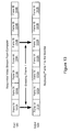
input 1302 andoutput 1304, according to one embodiment. As FIG. 13 shows, asequential video stream 1302 may be received from thecomputer 102. In this example, the video sequence comprisesframe 1Aframe 2Aframe 3Aframe 4Aframe 1Bframe 2Bframe 3B - As FIG. 13 shows, the
frame grabber 306A identifies and ‘grabs’frame 1Aframe grabber 306A may then send the grabbedframe 1Amonitor 108A, as shown in the first four frames of theoutput stream 1304. Then, once theframe grabber 306A detects the next frame from the first video source, i.e.,frame 1Bmonitor 108A, as shown. In one embodiment, the output frames may be sent to themonitor 108A at the monitor's refresh rate. Thus, the rates of the input and the output may differ, e.g., theframe grabber 306A may receive frames at a first rate, e.g., 60 Hz, while sending the output frames to themonitor 108A at a different rate, e.g., 75 Hz. - Thus, various embodiments of the systems and methods described herein may provide means for driving multiple monitors with a single computer, where multiplexed video frames may be transmitted over a single serial cable, and extracted sequentially by frame grabbers associated with respective monitors. Some of the points of novelty of various embodiments discussed herein include, but are not limited to, the following:
- 1. The video data stream is a sequence of complete image frames or windows;
- 2. A unique frame identification is attached to each frame;
- 3. Frames are totally independent of each other and are fully unique and complete images;
- 4. Frames need not be contiguous or continuous;
- 5. Frames are refreshed to the monitor independent of the how often they are rewritten to the frame grabber;
- 6. The frame grabber is an independent and complete frame reception node;
- 7. The system is scaleable from 2 to N nodes; and
- 8. The image (window) that contains the human interaction devices (typically the visually critical items such as the mouse) are rewritten more often to reduce the apparent ‘jerkiness’ of their perceived movement.
- Further modifications and alternative embodiments of various aspects of the invention will be apparent to those skilled in the art in view of this description. Accordingly, this description is to be construed as illustrative only and is for the purpose of teaching those skilled in the art the general manner of carrying out the invention. It is to be understood that the forms of the invention shown and described herein are to be taken as the presently preferred embodiments. Elements and materials may be substituted for those illustrated and described herein, parts and processes may be reversed, and certain features of the invention may be utilized independently, all as would be apparent to one skilled in the art after having the benefit of this description of the invention. Changes may be made in the elements described herein without departing from the spirit and scope of the invention as described in the following claims.
Claims (30)
Priority Applications (4)
| Application Number | Priority Date | Filing Date | Title |
|---|---|---|---|
| US10/198,719 US20030191850A1 (en) | 2002-04-08 | 2002-07-18 | Connecting multiple monitors to a computer using a single cable |
| AU2003212967A AU2003212967A1 (en) | 2002-04-08 | 2003-02-07 | Connecting multiple monitors to a computer using a single cable |
| PCT/US2003/003783 WO2003088670A1 (en) | 2002-04-08 | 2003-02-07 | Connecting multiple monitors to a computer using a single cable |
| US10/458,853 US7161557B2 (en) | 2002-04-08 | 2003-06-11 | Selectively updating a display in a multi-display system |
Applications Claiming Priority (2)
| Application Number | Priority Date | Filing Date | Title |
|---|---|---|---|
| US37088902P | 2002-04-08 | 2002-04-08 | |
| US10/198,719 US20030191850A1 (en) | 2002-04-08 | 2002-07-18 | Connecting multiple monitors to a computer using a single cable |
Related Child Applications (1)
| Application Number | Title | Priority Date | Filing Date |
|---|---|---|---|
| US10/458,853 Continuation-In-Part US7161557B2 (en) | 2002-04-08 | 2003-06-11 | Selectively updating a display in a multi-display system |
Publications (1)
| Publication Number | Publication Date |
|---|---|
| US20030191850A1 true US20030191850A1 (en) | 2003-10-09 |
Family
ID=28677978
Family Applications (1)
| Application Number | Title | Priority Date | Filing Date |
|---|---|---|---|
| US10/198,719 Abandoned US20030191850A1 (en) | 2002-04-08 | 2002-07-18 | Connecting multiple monitors to a computer using a single cable |
Country Status (3)
| Country | Link |
|---|---|
| US (1) | US20030191850A1 (en) |
| AU (1) | AU2003212967A1 (en) |
| WO (1) | WO2003088670A1 (en) |
Cited By (19)
| Publication number | Priority date | Publication date | Assignee | Title |
|---|---|---|---|---|
| US20030217198A1 (en) * | 2002-05-15 | 2003-11-20 | Nec-Mitsubishi Electrical Visual Systems Corporation | Image signal output apparatus and image signal control method |
| US20040044742A1 (en) * | 2002-08-29 | 2004-03-04 | Roni Evron | Multi-media system and method |
| US20060103651A1 (en) * | 2004-11-18 | 2006-05-18 | Amx Corporation | Method and computer program for implementing interactive bargraphs of any shape or design on a graphical user in interface |
| US20060170689A1 (en) * | 2003-01-17 | 2006-08-03 | Michael Maier | Image display system |
| US20070244967A1 (en) * | 2006-04-14 | 2007-10-18 | Microsoft Corporation | Appropriately rendering terminal server graphical data at multiple client side monitors |
| DE102006036901A1 (en) * | 2006-08-04 | 2007-10-25 | Siemens Ag | Television system for use in e.g. x-ray system, has imaging system separately controlling monitors and demultiplexers, where demultiplexers are attached and arranged proximate to monitors, and are connected with imaging system by data cable |
| US20080104166A1 (en) * | 2006-10-31 | 2008-05-01 | Carmen Elena Alvarez | Mobile operation support center |
| US20080195777A1 (en) * | 2007-02-08 | 2008-08-14 | Adder Technology Limited | Video switch and method of sampling simultaneous video sources |
| US20090040135A1 (en) * | 2007-08-08 | 2009-02-12 | International Business Machines Corporation | Automatic adjustment of display settings for remote viewing by an administrator |
| US20090157867A1 (en) * | 2007-12-18 | 2009-06-18 | International Business Machines Corporation | System and method for real-time graphic monitoring of differing graphics resolutions using a single graphics buffer |
| US7895442B1 (en) | 2007-06-18 | 2011-02-22 | Qurio Holdings, Inc. | Interconnect device to enable compliance with rights management restrictions |
| US20110170688A1 (en) * | 2006-12-15 | 2011-07-14 | Qurio Holdings, Inc. | Client-side protection of broadcast or multicast content for non-real-time playback |
| US8135947B1 (en) | 2007-03-21 | 2012-03-13 | Qurio Holdings, Inc. | Interconnect device to enable compliance with rights management restrictions |
| US9191605B1 (en) | 2007-03-26 | 2015-11-17 | Qurio Holdings, Inc. | Remote monitoring of media content that is associated with rights management restrictions |
| US9219945B1 (en) * | 2011-06-16 | 2015-12-22 | Amazon Technologies, Inc. | Embedding content of personal media in a portion of a frame of streaming media indicated by a frame identifier |
| WO2017082656A1 (en) * | 2015-11-12 | 2017-05-18 | Samsung Electronics Co., Ltd. | Display apparatus and control method thereof |
| CN110476418A (en) * | 2017-04-05 | 2019-11-19 | 三星电子株式会社 | Configure the display equipment and its control method of multidisplay system |
| CN112860202A (en) * | 2021-02-04 | 2021-05-28 | 苏州必捷网络有限公司 | Method for expanding computer desktop without additional display card |
| US11202028B2 (en) | 2017-04-05 | 2021-12-14 | Samsung Electronics Co., Ltd. | Display device configuring multi display system and control method thereof |
Citations (9)
| Publication number | Priority date | Publication date | Assignee | Title |
|---|---|---|---|---|
| US5539880A (en) * | 1993-09-28 | 1996-07-23 | Lakhani; Abdul-Malik H. | Cable-based interactive multimedia workstation network |
| US6073188A (en) * | 1997-07-25 | 2000-06-06 | Compaq Computer Corporation | Electronic switchbox for selection and sharing of internal peripheral devices among different computers, the internal peripheral devices located in slots of a chassis |
| US6104414A (en) * | 1997-03-12 | 2000-08-15 | Cybex Computer Products Corporation | Video distribution hub |
| US6119146A (en) * | 1998-05-04 | 2000-09-12 | Int Labs, Inc. | Computer network having multiple remotely located human interfaces sharing a common computing system |
| US6142913A (en) * | 1995-10-11 | 2000-11-07 | Ewert; Bruce | Dynamic real time exercise video apparatus and method |
| US6202211B1 (en) * | 1998-02-06 | 2001-03-13 | Henry R. Williams, Jr. | Method and apparatus for providing television signals to multiple viewing systems on a network |
| US20010000539A1 (en) * | 1997-12-15 | 2001-04-26 | Andrew Heller | Computer on a card with a remote human interface |
| US20030098820A1 (en) * | 1999-06-14 | 2003-05-29 | Mitsubishi Denki Kabushiki Kaisha | Image signal generating apparatus, image signal transmission apparatus, image signal generating method, image signal transmission method, image display unit, control method for an image display unit, and image display system |
| US6970183B1 (en) * | 2000-06-14 | 2005-11-29 | E-Watch, Inc. | Multimedia surveillance and monitoring system including network configuration |
-
2002
- 2002-07-18 US US10/198,719 patent/US20030191850A1/en not_active Abandoned
-
2003
- 2003-02-07 AU AU2003212967A patent/AU2003212967A1/en not_active Abandoned
- 2003-02-07 WO PCT/US2003/003783 patent/WO2003088670A1/en not_active Application Discontinuation
Patent Citations (9)
| Publication number | Priority date | Publication date | Assignee | Title |
|---|---|---|---|---|
| US5539880A (en) * | 1993-09-28 | 1996-07-23 | Lakhani; Abdul-Malik H. | Cable-based interactive multimedia workstation network |
| US6142913A (en) * | 1995-10-11 | 2000-11-07 | Ewert; Bruce | Dynamic real time exercise video apparatus and method |
| US6104414A (en) * | 1997-03-12 | 2000-08-15 | Cybex Computer Products Corporation | Video distribution hub |
| US6073188A (en) * | 1997-07-25 | 2000-06-06 | Compaq Computer Corporation | Electronic switchbox for selection and sharing of internal peripheral devices among different computers, the internal peripheral devices located in slots of a chassis |
| US20010000539A1 (en) * | 1997-12-15 | 2001-04-26 | Andrew Heller | Computer on a card with a remote human interface |
| US6202211B1 (en) * | 1998-02-06 | 2001-03-13 | Henry R. Williams, Jr. | Method and apparatus for providing television signals to multiple viewing systems on a network |
| US6119146A (en) * | 1998-05-04 | 2000-09-12 | Int Labs, Inc. | Computer network having multiple remotely located human interfaces sharing a common computing system |
| US20030098820A1 (en) * | 1999-06-14 | 2003-05-29 | Mitsubishi Denki Kabushiki Kaisha | Image signal generating apparatus, image signal transmission apparatus, image signal generating method, image signal transmission method, image display unit, control method for an image display unit, and image display system |
| US6970183B1 (en) * | 2000-06-14 | 2005-11-29 | E-Watch, Inc. | Multimedia surveillance and monitoring system including network configuration |
Cited By (31)
| Publication number | Priority date | Publication date | Assignee | Title |
|---|---|---|---|---|
| US20030217198A1 (en) * | 2002-05-15 | 2003-11-20 | Nec-Mitsubishi Electrical Visual Systems Corporation | Image signal output apparatus and image signal control method |
| US20040044742A1 (en) * | 2002-08-29 | 2004-03-04 | Roni Evron | Multi-media system and method |
| US7373414B2 (en) * | 2002-08-29 | 2008-05-13 | Amx Llc | Multi-media system and method for simultaneously delivering multi-media data to multiple destinations |
| US20060170689A1 (en) * | 2003-01-17 | 2006-08-03 | Michael Maier | Image display system |
| US20060103651A1 (en) * | 2004-11-18 | 2006-05-18 | Amx Corporation | Method and computer program for implementing interactive bargraphs of any shape or design on a graphical user in interface |
| US7342584B2 (en) | 2004-11-18 | 2008-03-11 | Amx, Llc | Method and computer program for implementing interactive bargraphs of any shape or design on a graphical user interface |
| US20070244967A1 (en) * | 2006-04-14 | 2007-10-18 | Microsoft Corporation | Appropriately rendering terminal server graphical data at multiple client side monitors |
| US7439937B2 (en) | 2006-04-14 | 2008-10-21 | Microsoft Corporation | Appropriately rendering terminal server graphical data at multiple client side monitors |
| DE102006036901A1 (en) * | 2006-08-04 | 2007-10-25 | Siemens Ag | Television system for use in e.g. x-ray system, has imaging system separately controlling monitors and demultiplexers, where demultiplexers are attached and arranged proximate to monitors, and are connected with imaging system by data cable |
| US20080104166A1 (en) * | 2006-10-31 | 2008-05-01 | Carmen Elena Alvarez | Mobile operation support center |
| US20110170688A1 (en) * | 2006-12-15 | 2011-07-14 | Qurio Holdings, Inc. | Client-side protection of broadcast or multicast content for non-real-time playback |
| US8000474B1 (en) | 2006-12-15 | 2011-08-16 | Quiro Holdings, Inc. | Client-side protection of broadcast or multicast content for non-real-time playback |
| US8274502B2 (en) | 2007-02-08 | 2012-09-25 | Adder Technology Limited | Video switch and method of sampling simultaneous video sources |
| US20080195777A1 (en) * | 2007-02-08 | 2008-08-14 | Adder Technology Limited | Video switch and method of sampling simultaneous video sources |
| EP1956832A3 (en) * | 2007-02-08 | 2009-07-29 | Adder Technology Limited | Video switch and method of sampling simultaneous video sources |
| US8850183B1 (en) | 2007-03-21 | 2014-09-30 | Qurio Holdings, Inc. | Interconnect device to enable compliance with rights management restrictions |
| US8135947B1 (en) | 2007-03-21 | 2012-03-13 | Qurio Holdings, Inc. | Interconnect device to enable compliance with rights management restrictions |
| US9191605B1 (en) | 2007-03-26 | 2015-11-17 | Qurio Holdings, Inc. | Remote monitoring of media content that is associated with rights management restrictions |
| US7895442B1 (en) | 2007-06-18 | 2011-02-22 | Qurio Holdings, Inc. | Interconnect device to enable compliance with rights management restrictions |
| US20110145935A1 (en) * | 2007-06-18 | 2011-06-16 | Qurio Holdings, Inc. | Interconnect device to enable compliance with rights management restrictions |
| US8245046B2 (en) | 2007-06-18 | 2012-08-14 | Qurio Holdings, Inc. | Interconnect device to enable compliance with rights management restrictions |
| US20090040135A1 (en) * | 2007-08-08 | 2009-02-12 | International Business Machines Corporation | Automatic adjustment of display settings for remote viewing by an administrator |
| US8013805B2 (en) | 2007-08-08 | 2011-09-06 | International Business Machines Corporation | Automatic adjustment of display settings for remote viewing by an administrator |
| US20090157867A1 (en) * | 2007-12-18 | 2009-06-18 | International Business Machines Corporation | System and method for real-time graphic monitoring of differing graphics resolutions using a single graphics buffer |
| US9219945B1 (en) * | 2011-06-16 | 2015-12-22 | Amazon Technologies, Inc. | Embedding content of personal media in a portion of a frame of streaming media indicated by a frame identifier |
| WO2017082656A1 (en) * | 2015-11-12 | 2017-05-18 | Samsung Electronics Co., Ltd. | Display apparatus and control method thereof |
| US10416951B2 (en) | 2015-11-12 | 2019-09-17 | Samsung Electronics Co., Ltd. | Display apparatus and control method thereof |
| CN110476418A (en) * | 2017-04-05 | 2019-11-19 | 三星电子株式会社 | Configure the display equipment and its control method of multidisplay system |
| EP3566434A4 (en) * | 2017-04-05 | 2020-04-01 | Samsung Electronics Co., Ltd. | Display device configuring multi display system and control method thereof |
| US11202028B2 (en) | 2017-04-05 | 2021-12-14 | Samsung Electronics Co., Ltd. | Display device configuring multi display system and control method thereof |
| CN112860202A (en) * | 2021-02-04 | 2021-05-28 | 苏州必捷网络有限公司 | Method for expanding computer desktop without additional display card |
Also Published As
| Publication number | Publication date |
|---|---|
| AU2003212967A1 (en) | 2003-10-27 |
| WO2003088670A1 (en) | 2003-10-23 |
Similar Documents
| Publication | Publication Date | Title |
|---|---|---|
| US7161557B2 (en) | Selectively updating a display in a multi-display system | |
| US20030191850A1 (en) | Connecting multiple monitors to a computer using a single cable | |
| US6628243B1 (en) | Presenting independent images on multiple display devices from one set of control signals | |
| US7456836B2 (en) | Image display system | |
| EP1092218B1 (en) | Multi-sourced video distribution hub | |
| US8471860B2 (en) | Optimization of memory bandwidth in a multi-display system | |
| US20040017333A1 (en) | Universal serial bus display unit | |
| EP0788048B1 (en) | Display apparatus interface | |
| CA2284176C (en) | Video distribution hub | |
| CN108449566A (en) | Video frame rate compensation is carried out by adjusting vertical blanking | |
| US20140285502A1 (en) | Gpu and encoding apparatus for virtual machine environments | |
| EP2017819A2 (en) | Display apparatus, host device and control methods thereof | |
| US20170206854A1 (en) | Device and method for displaying information on a screen arrangement having a plurality of individual screen modules | |
| CN112822438A (en) | Real-time control multichannel video manager | |
| US20050165994A1 (en) | Signal transmission over a wire pair | |
| US20120098841A1 (en) | Shared Video Management Subsystem | |
| US5627952A (en) | Information displaying system which displays combined video and graphics images | |
| US20060061517A1 (en) | Delivering pixels received at a lower data transfer rate over an interface that operates at a higher data transfer rate | |
| US6606098B1 (en) | Method and apparatus having an extended video graphics bus | |
| JP4018058B2 (en) | Image display system and image display apparatus | |
| Bundulis et al. | Architectural and technological issues in the field of multiple monitor display technologies | |
| KR100226655B1 (en) | Server signal controlling apparatus | |
| JP2004333522A (en) | Picture display device | |
| JP2006350368A (en) | Image display system, host device, and image display device | |
| JP4369499B2 (en) | Image display system |
Legal Events
| Date | Code | Title | Description |
|---|---|---|---|
| AS | Assignment |
Owner name: CLEARCUBE TECHNOLOGY, INC., TEXAS Free format text: ASSIGNMENT OF ASSIGNORS INTEREST;ASSIGNOR:THORNTON, BARRY;REEL/FRAME:013405/0670 Effective date: 20021003 |
|
| AS | Assignment |
Owner name: HORIZON TECHNOLOGY FUNDING COMPANY LLC, CONNECTICU Free format text: SECURITY AGREEMENT;ASSIGNOR:CLEARCUBE TECHNOLOGY, INC.;REEL/FRAME:016862/0048 Effective date: 20050524 |
|
| AS | Assignment |
Owner name: COMERICA BANK, CALIFORNIA Free format text: SECURITY AGREEMENT;ASSIGNOR:CLEARCUBE TECHNOLOGY, INC.;REEL/FRAME:016621/0707 Effective date: 20050721 |
|
| STCB | Information on status: application discontinuation |
Free format text: ABANDONED -- FAILURE TO RESPOND TO AN OFFICE ACTION |
|
| AS | Assignment |
Owner name: CLEARCUBE TECHNOLOGY INC., TEXAS Free format text: RELEASE BY SECURED PARTY;ASSIGNOR:COMERICA BANK;REEL/FRAME:021679/0175 Effective date: 20081003 |
|
| AS | Assignment |
Owner name: HORIZON TECHNOLOGY FUNDING COMPANY LLC,CONNECTICUT Free format text: RELEASE;ASSIGNOR:CLEARCUBE TECHNOLOGY, INC.;REEL/FRAME:024358/0521 Effective date: 20100427 |